EP3869498B1 - Akustisches system - Google Patents
Akustisches system Download PDFInfo
- Publication number
- EP3869498B1 EP3869498B1 EP19873640.7A EP19873640A EP3869498B1 EP 3869498 B1 EP3869498 B1 EP 3869498B1 EP 19873640 A EP19873640 A EP 19873640A EP 3869498 B1 EP3869498 B1 EP 3869498B1
- Authority
- EP
- European Patent Office
- Prior art keywords
- membrane
- sound
- duct
- shaped member
- sound source
- Prior art date
- Legal status (The legal status is an assumption and is not a legal conclusion. Google has not performed a legal analysis and makes no representation as to the accuracy of the status listed.)
- Active
Links
Images











Classifications
-
- F—MECHANICAL ENGINEERING; LIGHTING; HEATING; WEAPONS; BLASTING
- F24—HEATING; RANGES; VENTILATING
- F24F—AIR-CONDITIONING; AIR-HUMIDIFICATION; VENTILATION; USE OF AIR CURRENTS FOR SCREENING
- F24F13/00—Details common to, or for air-conditioning, air-humidification, ventilation or use of air currents for screening
- F24F13/24—Means for preventing or suppressing noise
-
- G—PHYSICS
- G10—MUSICAL INSTRUMENTS; ACOUSTICS
- G10K—SOUND-PRODUCING DEVICES; METHODS OR DEVICES FOR PROTECTING AGAINST, OR FOR DAMPING, NOISE OR OTHER ACOUSTIC WAVES IN GENERAL; ACOUSTICS NOT OTHERWISE PROVIDED FOR
- G10K11/00—Methods or devices for transmitting, conducting or directing sound in general; Methods or devices for protecting against, or for damping, noise or other acoustic waves in general
- G10K11/16—Methods or devices for protecting against, or for damping, noise or other acoustic waves in general
- G10K11/161—Methods or devices for protecting against, or for damping, noise or other acoustic waves in general in systems with fluid flow
-
- G—PHYSICS
- G10—MUSICAL INSTRUMENTS; ACOUSTICS
- G10K—SOUND-PRODUCING DEVICES; METHODS OR DEVICES FOR PROTECTING AGAINST, OR FOR DAMPING, NOISE OR OTHER ACOUSTIC WAVES IN GENERAL; ACOUSTICS NOT OTHERWISE PROVIDED FOR
- G10K11/00—Methods or devices for transmitting, conducting or directing sound in general; Methods or devices for protecting against, or for damping, noise or other acoustic waves in general
- G10K11/16—Methods or devices for protecting against, or for damping, noise or other acoustic waves in general
- G10K11/172—Methods or devices for protecting against, or for damping, noise or other acoustic waves in general using resonance effects
-
- F—MECHANICAL ENGINEERING; LIGHTING; HEATING; WEAPONS; BLASTING
- F24—HEATING; RANGES; VENTILATING
- F24F—AIR-CONDITIONING; AIR-HUMIDIFICATION; VENTILATION; USE OF AIR CURRENTS FOR SCREENING
- F24F13/00—Details common to, or for air-conditioning, air-humidification, ventilation or use of air currents for screening
- F24F13/24—Means for preventing or suppressing noise
- F24F2013/247—Active noise-suppression
Definitions
- the present invention relates to an acoustic system that includes a structure which causes a fluid including wind and/or heat to flow, such as a blower including a fan, and a duct attached thereto.
- the present invention particularly relates to an acoustic system that effectively muffles specific frequency noise generated by the fan in the duct.
- a ventilation duct such as an air conditioning duct to which a fan is attached, has been widely used for indoor air conditioning, ventilation, and/or air blowing, but noise reduction and miniaturization are strongly desired due to demand for indoor comfort, quietness, and the like.
- noise predominant at a specific frequency determined by the number of blades and a rotation speed of the fan has become a major problem of fan noise.
- the porous sound absorber Although a normal porous sound absorber can also be used in the duct, the porous sound absorber only lowers sound as a whole, and it is difficult to change a relative relationship in which the noise is loud only at the specific frequency. It is known that the predominant specific frequency sound is easy to be heard in the field of psychoacoustics, and a method of significantly lowering only specific sound is required, which is difficult for the normal porous sound absorber.
- the porous sound absorber is configured by a fiber-based sound absorber or a deteriorating material
- the fibers or peeled pieces are carried by the wind of the fan and fly as dust, having an effect on a device, or being discharged to the environment, which is not preferable.
- JP4215790B discloses a muffling device that effectively suppresses noise of a cooling fan used in a device having the cooling fan and a cooling duct, for example, a projection-type display device, such as a liquid crystal projector device.
- the muffling device disclosed in JP4215790B has, in the cooling duct, a resonance-type muffler configured by a reflecting plate that is formed, at a position facing an intake surface of the cooling fan, substantially parallel to the intake surface and reflects sound from the cooling fan, an air chamber that is provided on an opposite side to the cooling fan with the reflecting plate interposed therebetween, and a through hole that is provided in the reflecting plate and communicates with the air chamber.
- the intake surface of the cooling fan and a flow passage direction of the cooling duct are at a right angle
- the intake surface of the cooling fan and the reflecting plate of the resonance-type muffler for example, a sound absorption surface of a Helmholtz resonator, a plate surface of a plate-shaped sound absorber, or a membrane surface of a membrane-shaped sound absorber face each other.
- the fan and the duct are at a right angle, only a frequency, which is equal to or higher than a cutoff frequency of the duct and at which a higher-order mode of sound can be generated, is emitted from the fan and flows in a direction of the duct.
- the muffling device disclosed in JP4215790B can provide a silent duct that is small in size, is low-cost, and has a high a muffling effect.
- JP5499460B discloses a duct that is provided in a vehicle and causes air to be sent from an air conditioning device to a vehicle interior to flow therein, the duct being capable of absorbing sound at a relatively low frequency, such as engine sound and road noise.
- the duct disclosed in JP5499460B is connected to a plurality of sound absorbing structures each comprising a housing that has an open hollow region, first and second holes that are provided in the housing, and a membrane-shaped or plate-shaped vibrating body that closes an opening portion of the hollow region, so that the hollow regions communicate with each other via the first and second holes.
- the sound absorption of the duct corresponds to a mechanism that has a hole provided in a space of the hollow region between the housing and a membrane surface and absorbs sound causing resonance with a membrane by adjusting the length of the membrane surface in a width (horizontal) direction to ⁇ /4.
- each sound absorbing structure having a simple configuration performs sound absorption by converting sound waves into vibration and consuming sound wave energy as mechanical energy.
- the sound absorbing structure is suitable for absorbing, for example, low-frequency sound that comes from an engine room and the like and infiltrates into the vehicle interior or comes from the air conditioning device and infiltrates into the vehicle interior.
- US 2005/096882 A1 describes that low-frequency duct noise is relatively difficult to deal with by passive methods such as porous duct lining. Reactive methods like expansion chamber are rather bulky, while compact resonators are to narrow-banded. US 2005/096882 A1 shows that a suitably stretched thin membrane backed by a slender cavity can achieve a satisfactory performance from low to medium frequencies over an octave band.
- HUANG L ET AL "Suppression of broadband noise radiated by a low-speed fan in a duct",THE JOURNAL OF THE ACOUSTICAL SOCIETY OF AMERICA, AMERICAN INSTITUTE OF PHYSICS, 2 HUNTINGTON QUADRANGLE, MELVILLE, NY 11747, vol. 128, no. 1, 1 July 2010 (2010-07-01), pages 152-163, XP012135843,ISSN: 0001-4966, DOI: 10.1121/1.3372749 discloses that the attenuation of ducted fan noise remains a technical challenge in the low frequency range as traditional duct lining becomes ineffective, and proposes a reactive method to suppress the sound radiation from an axial-flow fan.
- the method is particularly effective in the low frequency region and covers a broad band. Its effect is derived from two mechanisms. One is the reduction in the confining effects of duct walls when the duct radius is increased; the other is the acoustic interference between the direct radiation from the fan and reflections by the duct junctions. This interference is always destructive for axial dipoles when the frequency approaches zero. This performance differs from normal passive control methods, which become totally ineffective toward zero frequency.
- An approximate plane-wave theory explains the essential physics of the method, and its quantitative prediction is found to agree well with a full numerical simulation using a spectral method of Chebyshev collocation. The latter is validated by experiment using an axial-flow fan in a duct of finite length. Broadband noise reduction is achieved while the flow speed is kept unchanged. Practical difficulties of implementation for a fan with high pressure increase are discussed.
- the resonance structure for example, a Helmholtz resonance structure disclosed in JP4215790B or an air column resonance structure can be examined, but the characteristic of the structures is that the structures have an opening portion.
- the resonating bodies are disposed in a system that causes wind to flow, such as a fan, there is a problem that wind noise is generated in the opening portion.
- the air column resonance structure is a structure that causes cavity noise in aerodynamic noise, generating new noise.
- a Helmholtz resonating body also has a structure where wind noise generated at the opening portion strongly generates specific sound due to an effect of the resonating body so that in a case where air is blown into the mouth of a PET bottle, the bottle is rung with specific sound. Due to these, the resonance structure having the opening portion is difficult to be applied to the system that causes wind to flow, such as the fan.
- the present inventor has examined muffling of specific frequency sound caused by blades of the fan with the use of a membrane-type resonance structure as disclosed in JP4215790B . Since the membrane-type resonance structure does not need an opening portion, the membrane-type resonance structure does not become a generation source of new wind noise in response to wind, unlike the Helmholtz resonance structure and the air column resonance structure. In this state, fan specific noise can be muffled by a resonance phenomenon.
- the cooling duct is an intake duct, and noise on an intake side of the fan can be muffled, there is a problem that noise transmitted from the fan to a downstream side of the duct along with an air flow, such as wind, cannot be muffled.
- JP4215790B has a problem of not being able to be applied to a system that causes the flow of high air volume since the diameter of the duct needs to be decreased.
- a rear surface of the membrane is opened and does not comprise a rear surface closed space for resonance, so that there is a problem that a large muffling effect cannot be obtained.
- the vibrating body such as the membrane vibrates due to a sound pressure difference between the hollow region and the vehicle interior, the sound pressure of sound in a predetermined frequency band, which is generated in the vehicle interior, is reduced, and the predetermined frequency band is set based on the resonant frequency of a spring mass system configured by a mass component of the vibrating body and a spring component of the hollow region. For this reason, there is a problem that the size of the membrane needs to be increased.
- JP5499460B since a frequency at which the sound pressure of wind exhaust sound of the blower is particularly high is determined by the specifications of the air conditioning device and the like, the wavelength of sound generated by the driving of the blower included in the air conditioning device is determined, and a length W of the membrane in the width direction corresponding thereto may be set. Since sound at a relatively low frequency including rotating sound of the blower, such as the fan, has a particularly high sound pressure at 500 Hz, the length of the membrane in the width direction is set to 160 mm, which is a length 1/4 of the wavelength of this sound.
- the wavelength of sound at 2 kHz is approximately 170 mm
- the size of wavelength/4 is necessary even in a case where the membrane is used, miniaturization is difficult.
- JP5499460B only discloses a configuration where the sound absorbing structures are disposed in a far-field of the fan and uses a membrane structure having a length in the width direction of ⁇ /4, there is also a problem that it is difficult to obtain a position optimizing effect even in a case of being disposed nearby the fan.
- An object of the present invention is to provide an acoustic system in which wind does not directly hit a membrane surface perpendicularly by eliminating the problems of the related art and disposing a small membrane-type resonance structure in a flow passage horizontal direction and wind noise can be eliminated since there is no through hole or no hole.
- the present inventor has examined that muffling of specific frequency sound caused by blades of a fan with the use of the membrane-type resonance structure, and has discovered the following points.
- the membrane-type resonance structure does not need an opening portion, the membrane-type resonance structure does not become a generation source of new wind noise in response to wind. In this state, fan specific noise can be muffled by a resonance phenomenon.
- a wind pressure has an effect on a sound absorbing material in a case where wind flows inside the duct.
- a direction in which wind flows and a vertical direction of the membrane are almost in a relationship of forming a right angle.
- the effect of the wind pressure is barely received, and the sound absorbing material functions even in a case where air volume changes.
- the invention provides an acoustic system according to independent claim 1. Preferred embodiments of the invention are described in the dependent claims.
- the weight of the duct can be reduced by replacing the duct with the membrane surface.
- a numerical range represented by using “to” means a range including numerical values before and after “to” as a lower limit value and an upper limit value.
- orthogonal and parallel include a range of errors allowed in the technical field to which the present invention belongs.
- “orthogonal” and “parallel” mean that an error is within ⁇ 20° with respect to orthogonal or parallel in a strict sense, and an error with respect to orthogonal or parallel in a strict sense is preferably 10° or less, more preferably 5° or less, and even more preferably 3° or less.
- the "same” includes a range of an error generally allowed in the technical field.
- a range of an error generally allowed in the technical field is included, for example, a case of 99% or more, 95% or more, or 90% or more is included in addition to a case of 100%.
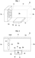
- Fig. 1 is a perspective view schematically showing an example of the acoustic system according to the embodiment of the present invention.
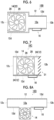
- Fig. 2 is a schematic cross sectional view showing the concept of the acoustic system shown in Fig. 1 .
- Fig. 3 is a schematic view showing the concept of the acoustic system shown in Fig. 1 .
- Fig. 4 is a partially broken perspective view of an example of a propeller fan used in the acoustic system shown in Fig. 1 .
- Fig. 3 is a schematic view showing a position where the fan is provided and the air flow of the fan is parallel to the duct as shown in Figs. 1 and 2 .
- the fan of the acoustic system is shown in the same manner as in Fig. 3 in the following as well, the direction of the air flow from the fan is to be understood as parallel to the duct.
- an acoustic system 10 has a quadrangular tubular duct 12, a fan 14 that is a sound source, and a membrane-type resonating body 16.
- the membrane-type resonating body 16 has a membrane-shaped member 18 and a frame 20.
- the duct 12 is a tubular member that has a through-hole 12a having a quadrangular cross section and has an open end 12b at one end portion on a downstream side.
- an end portion of the duct 12 on an upstream side where the fan 14, which is a sound source, is disposed may be an open end 12c, or may be closed.
- the duct 12 is provided with an opening 12e for attaching the membrane-shaped member 18, in a part of a wall 12d thereof.
- the duct has a function of causing wind generated by the fan 14, a gas, a fluid such as an air flow, heat of a fluid, or the like to flow therein.
- the duct 12 also propagates sound generated by the fan 14 simultaneously.
- the duct 12 is a duct, for example, a ventilation port where the fan 14 is provided, an air conditioning duct, or the like.
- the duct 12 is not particularly limited insofar as the fan 14 is provided, and may be a ventilation port, an air conditioning duct, or the like of a building, a house, an automobile, a train, an airplane, or the like, a duct or the like for electronic devices, such as a desktop personal computer (PC), a projector, and a server (computer server or the like), and a cooling fan particularly used in electronic devices, and a general duct and a general vent hole used for home appliances such as a ventilation fan, a dryer, a vacuum cleaner, a fan, a blower, and a dishwasher and various types of devices such as electrical devices.
- a cross sectional shape of the through-hole 12a of the duct 12 is not limited to a quadrangular shape, and may be various shapes such as a circular shape, an elliptical shape, and a polygonal shape including a triangular shape.
- the through-hole 12a of the duct 12 shown in Figs. 1 to 3 has the same dimension in a length direction
- the present invention is not limited thereto, and the cross sectional shape of the through-hole 12a may be reduced, or may be enlarged. That is, an inner wall surface of the through-hole 12a of the duct 12 may be inclined, or a step may be attached as in an acoustic system 10B shown in Fig. 6 .
- a dryer and a vacuum cleaner have a structure in which a portion of a motor fan is large and the vicinity of an opening portion is more narrowed down
- the structure can be regarded as a duct to which a step is attached as shown in Fig. 6 .
- the length of the duct 12 is not particularly limited insofar as the fan 14, which is a sound source, can be disposed inside the duct 12 on the upstream side or at an outer peripheral portion of the duct 12 on the upstream side, or the duct may have a sufficient length up to the open end 12b on the downstream side as shown in Figs. 1 to 3 . That is, a casing and a tubular body connected thereto may configure the duct 12.
- the duct 12 may be a tubular body configuring a casing 24 of the fan 14.
- the casing 24 of the fan 14 may configure the duct 12.
- the duct 12 is preferably a casing surrounding at least a part of the sound source. That is, the sound source is the fan 14, and the duct 12 is the fan casing 24 surrounding the fan, which is the sound source. From a viewpoint of making the entire structure small, it is preferable that the membrane-shaped member 18 and the frame 20 (the membrane-type resonating body 16) are attached to the fan casing 24.
- the diameter of the through-hole 12a (the inner diameter of the duct 12) is measured with the resolution of 1 mm.
- the cross sectional shape of the duct is not circular, it is preferable to convert the area to a diameter as an area equivalent to a circle to acquire the inner diameter.
- the material for the duct 12 is not particularly limited, but is preferably a metal or a resin.
- the metal include metals, such as aluminum, copper, tin, stainless steel (SUS), iron, steel, titanium, magnesium, tungsten, chromium, hot-dip galvanized steel, aluminum-zinc alloy plated steel sheet (galvalume steel sheet (registered trademark)), vinyl chloride coated steel, and various types of alloy materials.
- the resin include resin materials such as acryl, polycarbonate, polypropylene, vinyl chloride, urethane, urethane foam (a lightweight duct can be formed by using foam), a polyvinyl chloride resin (PVC), and synthetic resins thereof.
- the fan 14 is an internal sound source that generates a fluid (wind and/or an air flow including heat) flowing in the duct 12 and is disposed inside the duct 12 on the upstream side or at the outer peripheral portion of the duct 12 communicating with the inside of the duct 12 on the upstream side.
- the fan 14 is a sound source that generates specific frequency sound of which a sound pressure at least one specific frequency is maximum, that is, predominant sound.
- the predominant sound is defined as narrow band sound, and a peak sound pressure thereof is 3 dB or more higher than sound outside the band. This is because the sound can be sufficiently detected in a case where there is a difference of 3 dB.
- the fan 14 is not particularly limited insofar as a fan generates a fluid flowing in the duct 12, is an internal sound source, and can be disposed inside the duct 12 on the upstream side or at the outer peripheral portion thereof.
- a known fan in the related art can be used.
- Examples of the fan 14 include a propeller fan, an axial-flow fan, a blower fan, a sirocco fan, a cross flow fan, a mixed flow fan, a radial fan, a turbo fan, an air foil fan, and a plug fan.
- a propeller fan or an axial-flow fan which is used as the fan 14 has a plurality of blades and the plurality of blades rotate at a predetermined rotation speed, an air flow flowing in the duct 12 is generated, and predominant sound at a specific frequency, which is generated depending on the number and rotation speed of the blades configuring the fan 14 and is emitted from the fan 14 to the outside, is generated.
- rotation of 1/(the number of blades) results in the same disposition as the original disposition. That is, there is periodicity attributable to symmetry with respect to the rotation of 1/(the number of blades).
- the fundamental frequency (Hz) of predominant sound is determined by the number of blades ⁇ rotation speed (rps). At the fundamental frequency and an integral multiple frequency thereof, predominant sound is generated.
- a propeller fan 22 shown in Fig. 4 has the casing 24 that has a circular through-hole 24a and a fan main body 30 that consists of a propeller 28 having a plurality of blades attached to an outer periphery of a circular hub 26 at the center at equal intervals, that is, five blades in Fig. 4 , in the casing 24.
- the propeller fan 22 sucks a gas from the right in the drawing as shown by an arrow in the drawing, generates an air flow blown from the left, and generates predominant sound.
- the predominant sound is sound at a specific frequency depending on five, which is the number of blades of the propeller 28, and the rotation speed of the propeller 28.
- the fan 14 may be attached to the outer peripheral portion of the duct 12, an outlet of the fan 14 may be provided in the outer peripheral portion of the duct 12, and wind may be blown into the duct 12 perpendicularly to a direction in which a fluid flows in the duct 12.
- the fan 14 may be attached to an outer peripheral portion of the duct 12 on the other end portion side, and the other end portion of the duct 12 may be a closed end portion 12f.
- the fan 14 that is disposed in the duct 12 and generates noise is the most important sound source.
- a case where although a fan is attached to a ventilation fan, a range hood, or the like, there is a fan and wind or the like flows, that is, a case where the fan is not a sound source but sound coming in from the outside is a sound source, and the like are given as examples.
- there is unevenness or a duct side wall opening portion at a flow passage to which the fan is attached, and wind noise generated therein itself is also a sound source.
- an internal sound source that is disposed inside the duct 12 or at the outer peripheral portion of the duct 12, which communicates with the inside of the duct 12, an external sound source that is at a distance within a wavelength at a frequency of acoustic resonance on the outside from the end portion of the duct 12, and the like are described as sound sources.
- the membrane-type resonating body 16 has the membrane-shaped member 18 that is configured as a part of a wall of the duct 12 and vibrates in response to sound and the frame 20 that configures a rear surface closed space 20a of the membrane-shaped member 18.
- the membrane-type resonating body 16 causes acoustic resonance by a structure including the membrane-shaped member 18 and the rear surface closed space 20a of the frame 20 on a rear surface thereof, and suppresses sound that is transmitted from the fan 14, which is a sound source, into the duct 12 and is radiated from the end portion of the duct 12 on the downstream side.
- the structure including the membrane-shaped member 18 and the rear surface closed space 20a thereof is preferably a membrane-type resonance structure (membrane-type sound absorbing structure) in which a resonant frequency is determined by the membrane-shaped member 18 and the rear surface closed space 20a. That is, the membrane-type resonating body 16 exhibits a muffling function with the use of the membrane vibration of the membrane-shaped member 18 and selectively muffles sound at a specific frequency (frequency band).
- the membrane-type resonating body 16 is attached to one wall 12d of the duct 12 having a quadrangular cross section in the examples shown in Figs. 1 to 3
- the present invention is not limited thereto, as in the acoustic system 10A shown in Fig. 5 , the membrane-type resonating bodies may be attached to two upper and lower walls 12d in the drawing, or may be attached to all of four walls 12d.
- the outer periphery may be divided into several portions, and the membrane-type resonating bodies may be attached to some of the divided portions preferably symmetrically, or may be attached to the entire periphery.
- the membrane-type resonance structure is a structure in which a sound absorption coefficient of higher-order vibration is higher than a sound absorption coefficient of fundamental vibration.
- the peak frequency of the sound absorption coefficient becomes high by making the thickness of the rear surface closed space small.
- the membrane-shaped member 18 is particularly thin (more accurately, hardness is low)
- not only the peak frequency becomes high continuously when the thickness of the rear surface closed space is made small but also a new sound absorption peak appears further on a high frequency side. Consequently, in a case where a rear surface distance is made small, the sound absorption coefficient of a high frequency side peak becomes gradually higher than the sound absorption coefficient of a low frequency side peak. That is, in a case where a frequency at which a sound absorption coefficient is maximum is shown with respect to a rear surface distance, there is a discontinuous leap.
- This characteristic shows that a vibration mode in which a sound absorption coefficient is maximum shifts from a fundamental vibration mode to a higher-order vibration mode or a higher mode of the higher-order vibration mode. That is, in a case where the higher-order vibration mode is a state where excitation occurs easily due to the particularly thin membrane, by making the thickness of the rear surface space small, effects of sound absorption caused not only by the fundamental vibration mode but also by the higher-order vibration mode appear greatly. Accordingly, a sound absorption coefficient which is high in a high frequency range is not attributable to the fundamental vibration mode, but is caused by resonance in the higher-order vibration mode.
- the membrane-shaped member 18 of the membrane-type resonating body 16 is configured as a part of the wall 12d of the duct 12, and vibrates in response to sound.
- a membrane surface of the membrane-shaped member 18 is preferably parallel to a direction in which a fluid flows in the duct 12, but may be inclined insofar as the membrane surface forms less than 45° with respect to the direction in which the fluid flows.
- This inclination angle is more preferably less than 30°, even more preferably less than 15°, and most preferably less than 10°.
- the rear surface closed space 20a surrounded by the frame 20 and the membrane-shaped member 18 is formed by the frame 20.
- the rear surface closed space 20a is a closed space.
- the membrane-shaped member 18 is a thin membrane-shaped or foil-shaped member, and is attached to the opening 12e provided in a part of the wall 12d of the duct 12 directly or after being fixed to an opening end 20c of the frame 20.
- the membrane-shaped member 18 may be formed to vibrate as a part of the wall 12d of the duct 12 is made thin. By doing so, it is not necessary to use an adhesive or the like in order to fix the membrane-shaped member 18 to the wall 12d of the duct 12. In addition, since the membrane-shaped member 18 is made of the same material as the wall 12d of the duct 12, the same durability and the like as the duct are guaranteed.
- the membrane-type resonating body 16 which is manufactured by fixing a peripheral edge portion (edge portion) of the membrane-shaped member 18 to the opening end 20c of an opening portion 20b of the frame 20, to the opening 12e of the wall 12d of the duct 12 so that the membrane-shaped member 18 covers the opening portion 20b of the frame 20.
- the peripheral edge portion of the membrane-shaped member 18 is preferably a fixed end.
- the entire peripheral edge portion of the membrane-shaped member 18 may be fixed to the opening end 20c of the frame 20, or only a part thereof may be fixed. In this manner, the peripheral edge portion is supported by the frame 20 so as to be able to vibrate, and the frame 20 is fixed to the wall 12d of the duct 12.
- the peripheral edge portion of the membrane-shaped member 18 may also be fixed to an end surface of the opening 12e, or the peripheral edge portion of the membrane-shaped member 18 may be fixed to a portion of the wall 12d of a peripheral edge portion of the opening 12e.
- the entire peripheral edge portion (edge portion) of the membrane-shaped member 18 may be fixed to the end surface of the opening 12e or a portion of the wall 12d of the peripheral edge portion of the opening 12e, or only a part thereof may be fixed. In this manner, the membrane-shaped member 18 is supported by the opening 12e of the wall 12d of the duct 12 so as to be able to vibrate.
- a weight 32 is attached to a rear surface of the membrane-shaped member 18 on a rear surface closed space 20a side particularly in a case of a resonating body responding to low frequency sound. That is, the membrane-shaped member preferably has a mass distribution. By attaching the weight 32, the membrane-shaped member has the mass distribution. Consequently, the vibration mode can be changed, and the resonant frequency of the membrane-type resonating body 16 can be changed and adjusted, becoming likely to respond to the low frequency side in particular.
- the weight 32 may be attached to a surface side of the membrane-shaped member 18. As shown in Fig.
- a material for the membrane-shaped member 18 is not particularly limited, and can be selected depending on the acoustic unit 10, a muffling environment thereof, and the like, insofar as, in a case of being made into a membrane-shaped material or a foil-shaped material, the material has strength suitable for applying to a muffling target object described above, is resistant to a muffling environment of the acoustic unit 10, and is possible to membrane-vibrate in order for the membrane-shaped member 18 to perform muffling by absorbing or reflecting the energy of sound waves.
- the material for the membrane-shaped member 18 examples include a resin material that can be made into a membrane shape, such as polyethylene terephthalate (PET), triacetyl cellulose (TAC), polyvinylidene chloride (PVDC), polyethylene (PE), polyvinyl chloride (PVC), polymethylpentene (PMP), cycloolefin polymer (COP), zeonoa, polycarbonate, polyethylene naphthalate (PEN), polypropylene (PP), polystyrene (PS), polyarylate (PAR), aramid, polyphenylene sulfide (PPS), polyethersulfon (PES), nylon, PEs (polyester), cyclic olefin copolymer (COC), diacetyl cellulose, nitrocellulose, cellulose derivative, polyamide, polyamideimide, polyoxymethylene (POM), polyetherimide (PEI), polyrotaxane (slide ring material and the like), and polyimide
- the frame 20 has a rectangular parallelepiped shape, in which the rectangular opening portion 20b is formed in one surface and a rectangular bottom surface facing the opening portion 20b and four side surfaces are closed. That is, the frame 20 has a bottomed rectangular parallelepiped shape with one open surface.
- a small through-hole opening portion
- the hole can be treated as a substantially closed space for an acoustic phenomenon.
- ventilating inside and outside the frame 20 a difference between inside and outside pressures caused by a change in the atmospheric pressure, a change in a temperature, and the like can be eliminated.
- tension is applied to the membrane-shaped member 18, causing a change in the characteristic.
- dew condensation caused by humidity can also be prevented. Since there is a possibility of becoming a generation source of wind noise in a case where there is a through-hole in the membrane surface disposed on a duct flow passage side, by having a through-hole in another surface, durability and robustness with respect to a pressure, a temperature, and the like can be increased while preventing wind noise.
- the frame 20 has the rear surface closed space 20a formed on the rear surface of the membrane-shaped member 18 as the peripheral edge portion of the membrane-shaped member 18 is attached to the opening end 20c of the opening portion 20b so that the opening portion 20b is covered, and supports the membrane-shaped member 18 so as to be able to vibrate.
- the frame 20 has the rear surface closed space 20a formed on the rear surface of the membrane-shaped member 18 by being attached to cover the opening 12e of the wall 12d of the duct 12, to which the peripheral edge portion of the membrane-shaped member 18 is attached, and supports the membrane-shaped member 18 so as to be able to vibrate.
- the shapes of the frame 20 and the opening portion 20b thereof are planar shapes and rectangles in the examples shown in Figs. 1 to 3 , respectively, but are not particularly limited in the present invention, and may be, for example, polygonal shapes including quadrangles, such as a rectangular shape, a rhombus, and a parallelogram, triangles, such as a regular triangle, an isosceles triangle, and a right triangle, and regular polygons, such as a regular pentagon and a regular hexagon, circles, ellipses, or the like, or may be irregular shapes.
- the shapes of the frame 20 and the opening portion 20b thereof are both rectangular shapes in the examples shown in Figs. 1 to 3 , but are not particularly limited in the present invention. The shapes may be the same or may be different from each other.
- the sizes of such a frame 20 and such an opening portion 20b are not particularly limited, and may be set depending on a ventilation port, an air conditioning duct, or the like of a building, a house, an automobile, a train, and an airplane, or the like where the duct 12, which is a muffling target object applied in order to muffle the acoustic system 10 of the embodiment of the present invention, for example, the fan 14 described above is provided, a duct for electronic devices, such as a desktop personal computer, a projector, and a server (computer server or the like), and a cooling fan particularly used in electronic devices, a general duct, a general vent hole, or the like used for various types of devices including home appliances, such as a ventilation fan, a dryer, a vacuum cleaner, a fan, a blower, and a dishwasher, and electrical devices.
- the sizes of the frame 20 and the opening portion 20b thereof are sizes in plain view.
- a distance between facing sides passing through a center thereof, or a circle equivalent diameter can be defined.
- a circle equivalent diameter can be defined.
- a circle equivalent diameter and a radius are a diameter and a radius when converted into circles having the same area, respectively.
- a material for the frame 20 is not particularly limited, and can be selected depending on a muffling target object and a muffling environment thereof insofar as the material can support the membrane-shaped member 18, has strength suitable for applying to the acoustic unit 10 described above, and is resistant to the muffling environment of the acoustic unit 10.
- Examples of the material for the frame 20 include a metal material, a resin material, a reinforced plastic material, and a carbon fiber.
- the metal material include aluminum, titanium, magnesium, tungsten, iron, steel, chromium, chromium molybdenum, nichrome molybdenum, copper, and alloys thereof.
- examples of the resin material include an acrylic resin, polymethyl methacrylate, polycarbonate, polyamideid, polyarylate, polyetherimide, polyacetal, polyetheretherketone, polyphenylene sulfide, polysulfone, polyethylene terephthalate, polybutylene terephthalate, polyimide, an ABS resin (acrylonitrile-butadiene-styrene copolymer synthetic resin), polypropylene, and triacetyl cellulose.
- examples of the reinforced plastic material include carbon fiber reinforced plastics (CFRP) and glass fiber reinforced plastics (GFRP).
- types of rubber include natural rubber, chloroprene rubber, butyl rubber, EPDM (ethylene-propylene-diene rubber), silicone rubber, and a crosslinked structure thereof.
- a structure containing air that is, a foam material, a hollow material, a porous material, or the like can also be used as a frame material.
- the frame can be formed by using, for example, a closed-cell foam material or the like.
- various materials such as closed-cell polyurethane, closed-cell polystyrene, closed-cell polypropylene, closed-cell polyethylene, and closed-cell rubber sponge, can be selected.
- the plurality of types of materials for the frame 20 may be used in combination.
- the membrane-type resonating body 16 is attachable and detachable to and from the wall 12d around the opening 12e of the duct 12 and is mountable on the duct 12 later.
- a structure hooked on the opening 12e of the wall 12d of the duct 12 is attached to the membrane-type resonating body 16.
- the membrane-type resonating body 16 can be attached to the wall 12d, for example, simply by pushing.
- a muffling frequency can be customized.
- the membrane surface of the membrane-shaped member 18 may have unevenness, that is, a recess, and/or a protrusion on the wall 12d of the duct 12, as in acoustic systems 10F and 10G shown in Figs. 9A and 9B .
- the unevenness (the recess and/or the protrusion) of the membrane surface of the membrane-shaped member 18 on the wall 12d of the duct 12 is preferably 10 mm or less, more preferably 5 mm or less, and even more preferably 2 mm or less. In this manner, wind noise can be prevented from being generated.
- the Young's modulus of the membrane-shaped member 18 denoted by E (Pa)
- the thickness (rear surface distance) of the rear surface closed space 20a denoted by d (m)
- the circle equivalent diameter of a region where the membrane-shaped member 18 vibrates that is, the diameter of the opening portion 20b of the frame 20, which is the full length of a circle in a case where the membrane-shaped member 18 is fixed to the frame 20, denoted by ⁇ (m)
- the hardness E ⁇ t 3 (Pa ⁇ m 3 ) of the membrane-shaped member 18 is preferably 21.6 ⁇ d -1.25 ⁇ ⁇ 4.15 or less.
- the coefficient a is 11.1 or less, 8.4 or less, 7.4 or less, 6.3 or less, 5.0 or less, 4.2 or less, and 3.2 or less, which means that the lower the coefficient a, the more preferable.
- the hardness E ⁇ t 3 (Pa ⁇ m 3 ) of the membrane-shaped member 18 is preferably 2.49 ⁇ 10 -7 or more, is more preferably 7.03 ⁇ 10 -7 or more, is even more preferably 4.98 ⁇ 10 -6 or more, is still even more preferably 1.11 ⁇ 10 -5 or more, is particularly preferably 3.52 ⁇ 10 -5 or more, and is most preferably 1.40 ⁇ 10 -4 or more.
- the membrane-type resonating body 16 of the acoustic system 10 can be suitably excited in the higher-order vibration mode.
- the Young's modulus of the membrane-shaped member can be measured with the use of a dynamic measurement method using vibration, such as a free resonance natural vibration method, or a static measurement method, such as a tensile test and a compression test.
- a dynamic measurement method using vibration such as a free resonance natural vibration method
- a static measurement method such as a tensile test and a compression test.
- physical property values such as a manufacturer's test table may be used.
- Thickness measurement can be performed through various types of general measurement methods, such as a caliper, a profilometer, a laser microscope, and an optical microscope.
- physical property values such as a manufacturer's test table may be used.
- the rear surface space thickness can be measured in the same manner as the thickness measurement.
- the thickness of the frame may be measured as it is.
- the vibration of the membrane there are fundamental vibration and higher-order vibration, and the higher-order vibration naturally has the order. As the order increases, the mode of membrane vibration gradually becomes closer to energy, and finally becomes indistinguishable. At this time, the springiness of the membrane does not actually affect resonance, and only the mass of the membrane (and the size of the rear surface distance) contributes to the resonance.
- a larger muffling effect can be obtained.
- a plurality of membrane-type resonance structures may be disposed in a duct cross section, or the membrane-type resonance structures may be disposed in a plurality of rows in a duct flow passage direction.
- the center of the membrane-shaped member 18 is preferably positioned at a distance which is larger than (m ⁇ ⁇ /2 - ⁇ /4) and is smaller than (m ⁇ ⁇ /2 + ⁇ /4) from the position of the sound source (the fan 14).
- the center is more preferably positioned at a distance which is larger than (m ⁇ ⁇ /2 - ⁇ /8) and is smaller than (m ⁇ ⁇ /2 + ⁇ /8), and is even more preferably at a distance which is larger than (m ⁇ ⁇ /2 - ⁇ /12) and is smaller than (m ⁇ ⁇ /2 + ⁇ /12).
- the center of the membrane-shaped member 18 is preferably positioned at a distance which is less than ⁇ /4 from the position of the sound source (the fan 14).
- the center of the membrane-shaped member 18 is more preferably positioned at a distance less than ⁇ /8, and is even more preferably positioned at a distance less than ⁇ /12.
- the integer m 0 is satisfied.
- the center of the membrane-shaped member 18 can be shifted away from the position at a distance of (2n + 1) ⁇ ⁇ /4 (n is an integer of 0 or more), at which muffling is difficult, from the position of the sound source (the fan 14), and can be brought closer to the position of m ⁇ ⁇ /2 (m is an integer of 0 or more), which is excellent in muffling.
- the center of the membrane-shaped member 18 can be determined by the centroid position of the membrane-shaped member (membrane) 18. This is because vibration occurs around the centroid position.
- the measurement method of the position of the sound source can be determined by a vibrating surface position thereof.
- the measurement method can be determined by the center position of the fan 14 (the center position of the blades).
- the mechanism can be considered as follows.
- the membrane-shaped member is substantially parallel to the flow passage, for example, the membrane-shaped member is disposed as in Fig. 3 , an interface has a high local speed and a small sound pressure.
- the interface is where a free end reflects the local speed and a fixed end reflects the pressure.
- the sound pressure is maximum.
- an external sound pressure at the sound source position is large, the amplitude of a pressure generated from the sound source is high, so that a muffling effect for amplifying sound is unlikely to be obtained.
- the relationship is opposite to the case above.
- the sound pressure of the sound source is minimum, the disposition causes the sound not to be amplified, and the disposition causes a muffling effect to be likely to be obtained.
- the high impedance interface is almost at the same position as the fan, which is the sound source, as a duct diameter is narrowed by an axial portion.
- the sound source position high impedance reflection interface is satisfied often particularly in the case of the fan.
- reflection interface that reflects, at a frequency (specific frequency of predominant sound) where the sound pressure of the sound generated by the sound source such as the fan 14, at least some of the sound with a surface on which an impedance change occurs on a high impedance side from the sound source in the duct 12, the sound source, and the membrane-shaped member 18, it is preferable to suppress externally radiating sound toward an opposite side to the reflection interface.
- a case where the high impedance interface in the duct is closed by a wall harder than an internal fluid a case where of a structure in which a duct diameter is small, a case where a plate with a hole and/or a punching structure is disposed on a duct surface, a case where a louver is disposed, a case where a shaft is placed in a middle portion, and the like can be given.
- a space for a casing and the like is narrow on the rear surface side of the fan 14 and an open end 12c side.
- the surface is the reflection interface that reflects sound.
- an axial-flow fan surface itself also functions as the high impedance interface.
- the fan 14 which is disposed in the duct 12 and is the sound source
- the rear surface side of the fan 14, excluding an intake portion is the closed end portion 12f and is closed as shown in Figs. 9A and 9B and then reflection is performed also by blades of the rotating fan.
- the closed end portion 12f and the blades of the fan are the reflection interface where sound is reflected.
- the center of the membrane-shaped member 18 is preferably positioned at a distance which is larger than m ⁇ ⁇ /2 - ⁇ /4 and is smaller than m ⁇ ⁇ /2 + ⁇ /4 from the reflection interface that causes an acoustic impedance change.
- the center of the membrane-shaped member 18 is more preferably at a distance which is larger than (m ⁇ ⁇ /2 - ⁇ /8) and is smaller than (m ⁇ ⁇ /2 + ⁇ /8), and is even more preferably at a distance which is larger than (m ⁇ ⁇ /2 - ⁇ /12) and is smaller than (m ⁇ ⁇ /2 + ⁇ /12).
- the center of the membrane-shaped member 18 can be shifted away from the position at a distance of (2n + 1) ⁇ ⁇ /4 (n is an integer of 0 or more), at which muffling is difficult, from the reflection interface that causes an acoustic impedance change, and can be brought closer to the position of m ⁇ ⁇ /2 (m is an integer of 0 or more), which is excellent in muffling.
- the mechanism can be considered as follows.
- an interface including the membrane-shaped member 18 is at a position where acoustic impedance is minimum. That is, a local speed causes reflection at the free end and a sound pressure causes reflection at the fixed end.
- a local speed causes reflection at the fixed end, and a sound pressure causes reflection at the free end.
- the high impedance reflection interface, the sound source, the membrane-shaped member, and an open portion may be disposed in this order, or the sound source, the high impedance reflection interface, the membrane-shaped member, and the open portion may be disposed in this order.
- the case of the former include a structure where a louver is attached to the rear surface, there is the fan, and there is the opening portion through which wind is let out toward the front and a structure where the rear surface is narrowed down.
- the case of the latter, which is the high impedance reflection interface include a case where a louver, a fixed blade structure, and/or a current plate are attached to the front of the fan.
- the disposition causes a resonance phenomenon in the duct to be most unlikely to occur.
- a muffling effect caused by the membrane-shaped member 18 appears strongly, and the disposition causes a muffling effect of radiating sound to be most likely to occur.
- a reflection portion which includes the high impedance reflection interface described above, the sound source, such as the fan 14, and the membrane-shaped member 18 are disposed at a distance within ⁇ /2 and the radiating sound toward the opposite side to the reflection portion is suppressed.
- the size of the acoustic unit 10 can be made small.
- a three-dimensional model was constructed to implement membrane vibration, and an acoustic simulation was performed using the finite element method calculation software COMSOL ver.5.3 (COMSOL Inc.).
- an end portion interface (an opening surface of the open end 12b) open to the free space was an interface where an acoustic impedance change from a relatively high acoustic impedance side in the duct to a relatively low acoustic impedance of the free space occurred
- the interface was a surface where reflection and transmission caused by the low impedance interface in accordance with the impedance difference occurred.
- An object of the present invention is to suppress sound radiated from the open portion (the open end 12b) of the duct 12 to the space.
- a cylindrical rigid body wall (a hub 26) that had the middle of the duct simulating the shaft of the axial-flow fan, which was the fan 14, as a central shaft and had a diameter of 30 mm was disposed. Sound flowed through the outer peripheral portion (a portion that had a square shape of which one side was 75 mm, excluding a middle portion of ⁇ 30 mm) of the cylindrical wall 12d in the duct 12. Since the flow passage diameter of the duct 12 was narrow due to the central shaft, acoustic impedance was high at this place. Accordingly, at the internal sound source position, an impedance change from low impedance to high impedance occurred due to the narrowing of the duct, and the reflection interface was formed.
- the duct had the reflection interface where a change from high impedance to low impedance (outside) of the duct end portion occurred and the reflection interface where a change from a low impedance side to high impedance (the narrow duct) occurred on the rear surface side of the internal sound source.
- this model has simulated the axial-flow fan, without being limited to the axial-flow fan, a reflection interface caused by such high and low levels of impedance can be formed by various fans.
- Eight point sound sources simulating eight blades were disposed at equal intervals and rotationally symmetrically on the circumference of a circle having a diameter of 60 mm within the cross section of the duct 12 at the sound source position.
- the center position of the circle, the center of a shaft, and the center of the cross section of the duct 12 matched each other. Sound was radiated in the same phase from the eight point sound sources (eightfold symmetrical positions). This simulated radiating sound from the eight-blade fan.
- the membrane-type resonance structure the membrane-type resonating body 16, in which a PET film having a thickness of 100 ⁇ m was used as the membrane-shaped member (hereinafter, also simply referred to as the membrane) 18, four ends of the PET film, which was the membrane-shaped member 18, was restrained by being fixed to the square opening portion 20b of the frame 20 of which one side was 30 mm, the thickness of the rear surface closed space 20a of the membrane-shaped member 18 was set to 5 mm, and a rear surface thereof was closed by a wall, was used.
- the resonance structure was obtained by the vibration of a thin membrane, which is the PET film of which four ends were fixed, and reflection by a rear surface wall of the frame 20 via the rear surface closed space 20a.
- the design of the membrane-type resonating body 16 was characteristic in that the sound absorption coefficient of higher-order vibration was designed to be higher than the sound absorption coefficient of fundamental vibration. Although it was necessary to make a membrane body hard by increasing the thickness of the membrane-shaped member 18 in order to make the frequency of the fundamental vibration high, there was a problem that sound absorption and/or a phase change were unlikely to occur in a case of becoming a hard membrane that was difficult to vibrate, and it was difficult to obtain a membrane-type resonance structure that had a high frequency and a large muffling effect by using fundamental vibration. On the contrary, since a membrane can be used as the membrane-shaped member 18 by using higher-order vibration resonance, there is an advantage that high resonance effect can be obtained also on the high frequency side.
- Fig. 10 shows the normal incidence sound absorption coefficient of the membrane-type resonance structure, which is the membrane-type resonating body 16. Although sound absorption caused by fundamental vibration is approximately 1 kHz, the maximum value of the sound absorption is approximately 2 kHz, which is caused by higher-order vibration. Further, as shown in Fig. 1 , it is a characteristic of the membrane-type resonance structure that resonance occurs at a plurality of frequencies. In addition, since there is no hole opened in the membrane-type resonance structure, there is a characteristic that new wind noise is not generated in response to the wind of the fan 14.
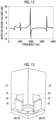
- Fig. 13 shows a simulation structure in which the membrane-type resonance structure was disposed in the duct.
- the membrane-type resonance structure which was the membrane-type resonating body 16
- the membrane-type resonance structure was disposed at a position separated from an internal sound source 34 of the duct 12 by 10 mm to an external radiation side.
- an interval between the center position of the membrane-type resonating body 16 and the position of the internal sound source 34 in the duct flow passage direction was 25 mm.
- Eightfold symmetrical disposition was adopted for the internal sound source 34.
- Muffled sound volume in a case where the membrane-type resonance structure was disposed only on one surface of the quadrangular duct 12 and muffled sound volume in a case where four membrane-type resonance structures were disposed symmetrically on all four surfaces of the quadrangular duct 12 as shown in Fig. 13 were calculated.
- a portion separated from the internal sound source position by 10 mm in the duct flow passage direction was a wall (a reflection wall 36: refer to Figs. 14A and 14B ) on the rear surface side of the internal sound source 34, and calculation was performed as a system reflecting sound.
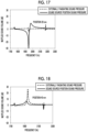
- Figs. 11 and 12 respectively show muffled sound volume in a case where one membrane-type resonance structure was disposed and muffled sound volume in a case where four membrane-type resonance structures were disposed.
- the muffled sound volume was calculated as a difference between externally radiating sound volume in a case where the membrane-type resonance structure was not disposed and externally radiating sound volume in a case where the membrane-type resonance structure was disposed.
- a state where there was no sound absorption by a membrane structure was caused. This could be set as only the real part of the Young's modulus of the membrane had a number numerically and the imaginary part was set to 0.
- a single device can perform muffling at a plurality of frequencies. This corresponds to the fact that the membrane-type resonance structure used in the present invention has a plurality of resonances caused by fundamental vibration and a plurality of higher-order vibrations.
- Fig. 14A shows a view of a sound pressure distribution (logarithmic expression as log10(P)) in which the sound pressure amplitude is logarithmically shown in shades.
- Fig. 14B shows a diagram of a local speed distribution shown by arrows after normalizing a local speed. This is the result at 1.945 kHz where a large muffling effect was obtained.
- white spots 34 indicate the sound sources 34 (enabled by the blades of the fan 14), white indicates that the sound pressure is high, and black and dark shades indicate that the sound pressure is low.
- the interference of canceling-out occurred due to interaction among the membrane-type resonance structure, the sound source, and a sound source rear surface (the reflection wall, the shaft, and the like).
- a distance between the two is short, near-field interference occurs, and in a case where the distance between the two is long, interference occurs in propagating waves.
- the reflection wall (reflection interface) 36 (refer to Figs. 14A and 14B ) was provided on the rear surface side (the open end 12c side) of the internal sound source (the fan 14 shown in Fig. 2 ). This was to simulate a phenomenon peculiar to the case of the fan 14.
- the causes of the occurrence of predominant sound at a specific frequency in the case of the fan 14 were the number of blades of the fan 14 and the continued radiation of sound at a frequency, which was a rotation speed, in phase. That is, the blades of the fan 14 were in a state of moving in synchronization with a predominant sound frequency.
- a change in the muffled sound volume was calculated by changing the position of the membrane-type resonance structure under the same condition (a case of four membrane-type resonance structures) as Simulation 1.
- Muffled sound volume at 1.945 kHz which was a resonant frequency, was calculated under each condition by changing a distance between the position of the internal sound source (34) and a lower end of the membrane-type resonance structure (16) from 5 mm to 85 mm. The results are shown in Fig. 15 .
- the muffled sound volume changed depending on the position of the membrane-type resonance structure.
- a distance in the graph shown in Fig. 15 was 20 mm, that is, a distance between the internal sound source and the center of the membrane-shaped member 18 was 35 mm, and a distance between the reflection wall on the rear surface side of the internal sound source and the center of the membrane-shaped member 18 was 45 mm, it was found out that there was a condition where a muffling effect was hardly seen.
- the level of a sound pressure at the internal sound source position was calculated. It is known that as the sound pressure at the internal sound source position increases, the radiation amount of sound from the sound source increases.
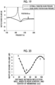
- the muffled sound volume of externally radiating sound and muffled sound volume at an internal sound pressure position are shown in Fig. 16 in a case of the position of 5 mm (a near-field interference region), in Fig. 17 in a case of position of 20 mm (an extreme internal sound source position amplification region), in Fig. 18 in a case of 40 mm, and in Fig. 19 in a case of 80 mm. That is, an effect of placing the membrane-type resonance structure was expressed as a difference with a condition without the membrane-type resonance structure as reference.
- Fig. 17 shows a condition where externally radiating sound was hardly muffled.
- the amplification (a minus direction in Fig. 17 ) of an extremely large sound pressure occurred at the position of the internal sound source. For this reason, it was found out that sound radiated from the sound source was strongly (30 dB or more) amplified, offsetting the muffling effect of the externally radiating sound by the membrane-type resonance structure. Consequently, the muffling effect disappeared.
- the membrane-type resonance structure also exhibited reflection since a phase change occurred at a resonant frequency. Sound reflected by the membrane-type resonance structure was again reflected by the wall (36) behind the sound source, and returned to the position of the membrane-type resonance structure. Further, the sound was reflected again at the position of the membrane-type resonance structure. In a case where sounds reflected by the membrane-type resonance structure are in phase with each other, the reflections overlap each other, causing strong resonance. That is, a resonator for sound caused by the position of the membrane-type resonance structure (16) in the duct 12 and the position of the wall (36) behind the sound source is formed.
- ⁇ /4 at a wavelength of 2 kHz was approximately 43 mm.
- the condition is a condition where a distance between the reflection wall (36), which was the sound source rear surface, and the membrane-type resonance structure (16) was 45 mm, a resonator that was extremely close to the resonance condition and was strong in the duct was formed.
- a sound pressure in the duct centered around the inside of the resonator was extremely greatly amplified due to a resonance phenomenon.
- the sound pressure at the internal sound source position was amplified. It was found out that as the sound pressure of the internal sound source was increased by the resonator in this manner, radiating sound volume from the sound source increased, causing an effect of offsetting a muffling effect by the membrane-type resonance structure.
- Fig. 21 shows a muffled sound volume spectrum in this case (a point B of Fig. 20 ). It is found out that externally radiating sound was barely muffled.
- the muffled sound volume increased in a case where it was avoided that the distance became ⁇ /4, and the muffled sound volume was maximum in a case of approximately m* ⁇ /2 (m was an integer of 0 or more).
- reflected waves of the membrane-type resonance structure had a phase relationship of not overlapping each other, which was a condition where a resonator was most unlikely to be formed in the duct 12. For this reason, without amplifying a sound pressure at the sound source position, the largest muffling effect by the membrane-type resonance structure was obtained.
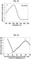
- Fig. 24 shows a change in the muffled sound volume in a case where the position of the membrane-type resonance structure was changed. It was found out that even in a case where a distance from the sound source to the reflection wall, which was the rear surface, was changed, as in Simulation 3, the muffling effect was smallest when a distance between the reflection wall and the membrane-type resonance structure was ⁇ /4, and the muffling effect increased on both sides thereof.
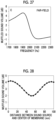
- Figs. 25 to 27 each show a muffling spectrum at a position thereof.
- FIG. 28 shows a change in the muffled sound volume when the position of the membrane-type resonance structure was changed as in Simulation 4 in this case.
- the distance was set to a distance between the position of the sound source (34) and the center position of the membrane-type resonance structure (16).
- the muffled sound volume changed at the position of the membrane-type resonance structure.
- the muffled sound volume was smallest.
- the muffled sound volume maximized when at the position of approximately m ⁇ ⁇ /2.
- a muffling mechanism (the membrane-type resonating body alone) is as follows.
- phase reversal was performed depending on the characteristic of the membrane-type resonating body 16 regardless of a distance between the sound source 34 and the membrane-type resonating body 16. For this reason, a frequency was determined by the membrane-type resonating body 16 alone. Therefore, the phase change of transmitted waves caused by the resonance of the membrane-type resonating body 16 alone was important.
- An amplifying mechanism (resonator depending on a length) is as follows.
- the length of a cavity was one fourth ( ⁇ /4) of the wavelength.
- sound from the sound source 34 was strongly radiated by increasing a sound pressure at the position of a sound source 24. For this reason, the externally radiating sound also increased. This was based on the resonance characteristic of the cavity formed by the reflection wall 36 and the membrane-type resonating body 16. Therefore, when a distance between the reflection wall 36 and the membrane-type resonating body 16 was ⁇ /4, a resonance effect was large. For this reason, a distance between the reflection phase of the membrane-type resonating body 16 and the reflection wall 36, which was the rear surface, was important.
- Both of the muffling mechanism and the amplifying mechanism worked at a frequency near the resonance of the membrane-type resonating body 16.
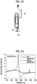
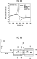
- Figs. 34 and 35 show, in a case where the distance between the reflection wall 36, which was the rear surface, and the center of the membrane 18 was 30 mm, and a case where the distance was 105 mm, a relationship between a frequency and muffled sound volume for a case where there was sound absorption by the membrane-type resonating body 16 and a case where there was no sound absorption.
- the membrane-type resonating body is to be disposed avoiding this distance of ⁇ /4.
- muffling can be performed for the predominant sound of the sound source by configuring an acoustic unit in which the membrane-type resonating body is disposed on the wall of the duct.
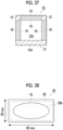
- one end surface of the duct 12 having cross section disposition shown in Fig. 37 was configured by fitting the membrane-type resonating body 16 having width 30 mm ⁇ length 60 mm ⁇ width 10 mm, which is shown in Fig. 38 , into each of an upper surface, which was one end surface, and both side surfaces of the duct 12 that had the through-hole 12a having a square cross section of 60 mm ⁇ 60 mm, had external dimensions of 80 mm ⁇ 80 mm consisting of the wall 12d having a thickness of 10 mm, and had a length of 145 mm.
- the fan 14 which had a square shape of 60 mm ⁇ 60 mm and had a thickness of 28 mm, was attached to the one end surface of the duct 12 configured as described above, and the through-hole 12a of the duct 12 was configured to be covered with the fan 14, configuring the acoustic unit 10.
- a microphone 38 was attached at a position separated at a right angle by 140 mm from a position 200 mm downstream from the center of the other open end 12b of the duct 12 on the left in the drawing of the acoustic unit 10, configuring an experimental system measuring the noise of the acoustic unit 10.
- the membrane-type resonating body 16 had the opening portion 20b that had an elliptical shape having a major axis of 5.6 mm and a minor axis of 2.6 mm.
- the membrane-shaped member 18 made of polyethylene terephthalate (PET) having a thickness of 125 ⁇ m was bonded to an upper surface of the upper acrylic plate to cover the opening portion 20b.
- PET polyethylene terephthalate
- a noise measurement system of the acoustic unit 10 shown in Fig. 36 which was configured as described above, as the three membrane-type resonating bodies 16 could be moved downstream from the position of the fan 14, the center position of the membrane-type resonating bodies 16 with respect to the sound source (the fan 14) (a distance between the center position of the blades of the fan 14 and the center position of the membrane-type resonating bodies 16 in a cross section in the duct flow passage direction) was changed, and the sound pressure of noise radiated from the duct of the acoustic unit 10 according to the embodiment of the present invention when the fan 14 was rotated at a rotation speed of 13,800 rpm was measured by the microphone 38.
- FIG. 39 shows the sound pressure in a case where the membrane-type resonating body 16 was not disposed as reference. In addition, Fig. 39 also shows sound absorption through muffling by a muffler when the membrane-type resonating bodies 16 functioned as the muffler.
- Fig. 40 shows a relationship between a center position/ ⁇ of the membrane-type resonating body 16 with respect to the fan 14 and a transmission loss at 1,150 Hz. That is, a microphone sound pressure in a case where the membrane-type resonating body 16 is disposed at each position at 1,150 Hz and a reference microphone sound pressure where the membrane-type resonating body is not disposed were compared to each other, and the result was expressed as a transmission loss. Points shown in Fig. 40 are all examples of the present invention.
- Fig. 39 shows that a thick solid line of Example 1 had a significantly lower sound pressure than a dotted line of reference, and a larger muffling effect than the reference. That is, it is found out that Example 1, in which the position of the membrane-type resonating body 16 was ⁇ /2, had a large muffling effect.
- a transmission loss amount increased in a case where the distance to the fan was made closer than ⁇ /4.
- the position was 0.12 ⁇ , and the transmission loss exceeded 4 dB.
- the optimum value of the transmission loss was a position m ⁇ ⁇ /2 (m was an integer of 0 or more) in a case of being combined with the simulations.
- the muffling effect of the membrane-type resonating body 16 had the position dependence of the membrane-type resonating body 16, and bringing the position of the membrane-type resonating body 16 further away from ⁇ /4 and bringing closer to 0 or ⁇ /2 were desirable.
- the microphone 38 was disposed at a position separated at a right angle by 100 mm from a position 100 mm downstream side instead of the position separated at a right angle by 140 mm from the position 200 mm downstream side.
- the membrane-shaped member 18 of the membrane-type resonating body 16 was made of polyethylene terephthalate (PET) having a thickness of 125 ⁇ m, and the rear surface distance was 5 mm.
- PET polyethylene terephthalate
- the resonant frequency of the acoustic unit 10a having this structure was 1,500 Hz.
- the acoustic unit 50 of Comparative Example 1 was configured as in the acoustic unit 10a of Example 2 except for using the Helmholtz resonating bodies 52 to be compared to, instead of the membrane-type resonating bodies 16. That is, the number and disposed positions of the Helmholtz resonating bodies 52 were the same as those of the membrane-type resonating bodies 16 of Example 2.
- the Helmholtz resonating bodies 52 to be compared to was designed such that each volume thereof was the same as the membrane-type resonating body 16.
- the thickness of a surface plate 54 was 2 mm
- the rear surface distance was 3 mm
- the rear surface was a ⁇ 26 mm cylindrical cavity
- a through hole (resonance hole) 56 that had a hole diameter of 2.5 mm and a thickness of 2 mm was in the surface plate 54.
- the resonant frequency was also 1,500 Hz.
- Each frame and a structure such as the surface plate 54 of the Helmholtz resonating body 52 were prepared by processing an acrylic plate with a laser cutter.
- the disposed positions of the membrane-type resonating body 16 and the Helmholtz resonating bodies 52 were determined to be positions attached to an exhaust side fan end portion. That is, frame portions of the membrane-type resonating body 16 and the Helmholtz resonating body 52 were disposed at positions in contact with the casing of the fan 14 as in Fig. 36 .
- Fig. 43 shows a microphone position sound pressure near fan peak sound when the resonating body was not disposed (Reference Example 1), the membrane-type resonating body 16 was disposed (Example 2), and the Helmholtz resonating body 52 was disposed (Comparative Example 1).
- the generated wind noise component interacted with the Helmholtz resonating body 52.
- the wind noise component was trapped in the resonating body and was enhanced near the resonant frequency of Helmholtz resonance.
- the enhanced component was again radiated from the Helmholtz resonating body through the opening portion, causing a strong wind noise source which had a characteristic frequency. Due to this effect, the sound volume was increased near the Helmholtz resonant frequency (this is exactly the same phenomenon which occurred when a PET bottle was blown).
- the membrane-type resonating body did not generate wind noise including a frequency around peak sound as well. Accordingly, without increasing sound volume, a large muffling effect could be obtained at the peak sound frequency. Accordingly, it was found out that the membrane-type resonating body that does not have the opening portion is more suitable to muffling than the resonance structure that has the opening portion, such as Helmholtz resonance.
- Example 3 In a measurement system which was the same as in Example 2, an experiment of obtaining a larger muffling effect was performed by disposing the membrane-type resonating bodies 16 in the duct flow passage direction in two rows (Example 3) and four rows (Example 4) instead of one row.
- Fig. 44 shows an image diagram in a case of four-row disposition.
- Fig. 45 shows the results.
- Fig. 45 shows a microphone position sound volume spectrum measured under each disposition condition of the membrane-type resonating bodies 16.
- Table 1 shows comparison of peak sound volume including the results of Example 2. It was found out that a larger muffling effect was obtained by disposing the membrane-type resonating bodies 16 in a plurality of rows in the duct flow passage direction. In a case of being arranged in four rows, a muffling effect of 15 dB or more could be obtained.
- Example 2 After a flow meter measured a wind speed in each of Example 2, Example 3, and Example 4, it was found out that the speeds of all of the examples were 7.8m/s. This was the wind speed which was the same in a case where the membrane-type resonating body 16 was not disposed. It was found out that air volume was not impaired by disposing the membrane-type resonating bodies 16 on the wall surface.
Landscapes
- Engineering & Computer Science (AREA)
- Physics & Mathematics (AREA)
- Acoustics & Sound (AREA)
- Multimedia (AREA)
- Chemical & Material Sciences (AREA)
- Combustion & Propulsion (AREA)
- Aviation & Aerospace Engineering (AREA)
- Fluid Mechanics (AREA)
- Mechanical Engineering (AREA)
- General Engineering & Computer Science (AREA)
- Soundproofing, Sound Blocking, And Sound Damping (AREA)
- Duct Arrangements (AREA)
Claims (19)
- Akustisches System (10) umfassend:einen Kanal (12), der eine Funktion hat, ein Fluid darin fließen zu lassen, und der eine röhrenförmige Form hat;eine Schallquelle; undmindestens einen Resonanzkörper vom Membrantyp (16),wobei der mindestens eine Resonanzkörper vom Membrantyp (16) mindestens ein membranförmiges Element (18), das geschlossen und als Teil einer Wand des Kanals (12) ausgebildet ist und in Reaktion auf Schall schwingt, und einen Rahmen (20), der an einer hinteren Oberflächenseite des membranförmigen Elements (18) so angebracht ist, dass er einen geschlossenen oder im Wesentlichen geschlossenen Raum (20a) auf der hinteren Oberflächenseite des membranförmigen Elements (18) bildet, aufweist, wobei der mindestens eine Resonanzkörper vom Membrantyp (16) konfiguriert ist, eine akustische Resonanz durch eine Struktur zu verursachen, die das mindestens eine membranförmige Element (18) und den geschlossenen oder im Wesentlichen geschlossenen Raum (20a) umfasst, und Schall zu unterdrücken, der von der Schallquelle in den Kanal (12) übertragen und von einem stromabwärtigen Endabschnitt des Kanals (12) abgestrahlt wird,wobei die Schallquelle entweder eine interne Schallquelle oder eine externe Schallquelle ist, wobei im Falle der internen Schallquelle die interne Schallquelle innerhalb des Kanals (12) oder an einem äußeren peripheren Abschnitt des Kanals (12) angeordnet ist, der mit einer Innenseite des Kanals (12) in Verbindung steht, und im Falle der externen Schallquelle die externe Schallquelle sich in einem Abstand innerhalb einer Wellenlänge bei einer Frequenz der akustischen Resonanz auf der Außenseite von einem stromaufwärtigen Endabschnitt des Kanals (12) befindet,wobei für mindestens ein membranförmiges Element (18) oder mindestens einen Resonanzkörper vom Membrantyp (16) in einem Fall, in dem eine Wellenlänge, die aus einer Frequenz bestimmt wird, bei der ein Schalldruck von von der Schallquelle (14) erzeugten Schalls maximal ist, mit λ bezeichnet wird und eine ganze Zahl von 0 oder mehr mit m bezeichnet wird, ein Zentrum des membranförmigen Elements in einem Abstand positioniert ist, der größer als (m × λ/2 - λ/4) und kleiner als (m × λ/2 + λ/4) von einer Position der Schallquelle (14) ist, undwobei in einem Fall, in dem ein Elastizitätsmodul des membranförmigen Elements mit E (Pa) bezeichnet wird, eine Dicke mit t (m) bezeichnet wird, eine Dicke des geschlossenen oder im Wesentlichen geschlossenen Raums (20a) mit d (m) bezeichnet wird und ein kreisäquivalenter Durchmesser eines Bereichs, in dem das membranförmige Element schwingt, mit Φ (m) bezeichnet wird, die Härte E × t3 (Pa ×m3) des membranförmigen Elements 21,6 × d-1,25 × Φ4,15 oder weniger beträgt.
- Akustisches System (10) gemäß Anspruch 1,wobei das Fluid ein Gas ist und in dem Kanal (12) als eines von Wind und/oder einem Luftstrom einschließlich Wärme fließt, undin dem Kanal (12) eine Richtung, in der das Fluid strömt, und eine Membranoberfläche des membranförmigen Elements (18) nicht senkrecht zueinander sind.
- Akustisches System (10) gemäß Anspruch 1 oder 2,
wobei die Schallquelle (14) eine Schallquelle ist, die einen vorherrschenden Schall erzeugt, von dem ein Schalldruck bei mindestens einer spezifischen Frequenz maximal ist. - Akustisches System (10) gemäß Anspruch 3,wobei die Schallquelle (14) ein Ventilator ist, undder vorherrschende Schall ein Schall ist, der durch einen Flügel, der den Ventilator bildet, und eine Rotationsgeschwindigkeit erzeugt wird und von dem Ventilator nach außen abgestrahlt wird.
- Akustisches System (10) gemäß einem der Ansprüche 1 bis 4,
wobei das membranförmige Element (18) an einer Öffnung (12e) angebracht ist, die in einem Teil der Wand (12d) des Kanals (12) vorgesehen ist. - Akustisches System (10) gemäß Anspruch 5,
wobei ein Kantenabschnitt des membranförmigen Elements ein fixiertes Ende ist. - Akustisches System (10) gemäß einem der Ansprüche 1 bis 4,
wobei das membranförmige Element geformt wird zu schwingen, dass es schwingt, indem ein Teil der Wand des Kanals (12) dünn gemacht wird. - Akustisches System (10) gemäß einem der Ansprüche 1 bis 7,
wobei die Struktur mit dem membranförmigen Element (18) und dem geschlossenen oder im Wesentlichen geschlossenen Raum (20a) eine Resonanzstruktur vom Membrantyp ist, bei der eine Resonanzfrequenz durch das membranförmige Element (18) und den geschlossenen oder im Wesentlichen geschlossenen Raum (20a) bestimmt wird. - Akustisches System (10) gemäß Anspruch 8,
wobei die Resonanzstruktur vom Membrantyp eine Struktur ist, in der ein Schallabsorptionskoeffizient einer Schwingung höherer Ordnung höher ist als ein Schallabsorptionskoeffizient einer Grundschwingung. - Akustisches System (10) gemäß einem der Ansprüche 1 bis 9,
wobei die membranförmigen Elemente (18) in einer Vielzahl von Reihen in einer Strömungsdurchgangsrichtung des Kanals (12) angeordnet sind. - Akustisches System (10) gemäß einem der Ansprüche 1 bis 10,
wobei das membranförmige Element (18) eine Massenverteilung aufweist. - Akustisches System (10) gemäß einem der Ansprüche 1 bis 11,
wobei ein Gewicht an dem membranförmigen Element (18) angebracht ist. - Akustisches System (10) gemäß Anspruch 12,
wobei das Gewicht an der Rückseite des membranförmigen Elements (18) angebracht ist. - Akustisches System (10) gemäß einem der Ansprüche 1 bis 13,
wobei für mindestens ein membranförmiges Element (18) oder mindestens einen Resonanzkörper vom Membrantyp (16) in einem Fall, in dem eine Wellenlänge, die aus einer Frequenz bestimmt wird, bei der ein Schalldruck von von der Schallquelle erzeugtem Schall maximal ist, mit λ bezeichnet wird, ein Zentrum des membranförmigen Elements (18) in einem Abstand positioniert ist, der kleiner als λ/4 von einer Position der Schallquelle (14) ist. - Akustisches System (10) gemäß einem der Ansprüche 1 bis 14,
wobei der Kanal (12) ein Gehäuse ist, das zumindest einen Teil der Schallquelle (14) umgibt. - Akustisches System (10) gemäß einem der Ansprüche 1 bis 15,wobei die Schallquelle ein Ventilator ist,der Kanal (12) ein Ventilatorgehäuse ist, das den Ventilator umgibt, unddas membranförmige Element (18) an dem Ventilatorgehäuse (24) befestigt ist.
- Akustisches System (10) gemäß einem der Ansprüche 1 bis 16,
wobei eine Grenzfläche hoher Impedanz zusammen mit der Schallquelle und dem membranförmigen Element vorhanden ist, um nach außen abstrahlenden Schall zu unterdrücken, der von dem Kanal (12) emittiert wird, wobei die Grenzfläche hoher Impedanz eine Reflexionsgrenzfläche ist, bei der sich eine Impedanz von der Schallquelle zu einer Seite hoher Impedanz in dem Kanal (12) ändert, und zumindest einen Teil des Schalls bei einer Frequenz reflektiert, bei der ein Schalldruck von von der Schallquelle erzeugtem Schall maximal ist, wobei für mindestens ein membranförmiges Element oder mindestens eine Resonanzstruktur vom Membrantyp in einem Fall, in dem eine Wellenlänge, die aus der Frequenz bestimmt wird, bei der der Schalldruck des von der Schallquelle erzeugten Schalls maximal ist, mit λ bezeichnet wird und eine ganze Zahl von 0 oder mehr mit m bezeichnet wird, ein Zentrum des membranförmigen Elements in einem Abstand positioniert ist, der größer als m × λ/2 - λ/4 und kleiner als m × λ/2 + λ/4 von der Reflexionsgrenzfläche ist, die die akustische Impedanzänderung verursacht. - Akustisches System (10) gemäß Anspruch 17,
wobei für mindestens ein membranförmiges Element oder mindestens eine Resonanzstruktur vom Membrantyp in einem Fall, in dem die Wellenlänge, die aus der Frequenz bestimmt wird, bei der der Schalldruck des von der Schallquelle erzeugten Schalls maximal ist, mit λ bezeichnet wird, das Zentrum des membranförmigen Elements an einer Position innerhalb von ±λ/4 von der Grenzfläche hoher Impedanz positioniert ist. - Akustisches System (10) gemäß Anspruch 17,
wobei ein Reflexionsabschnitt enthaltend die Reflexionsgrenzfläche, die Schallquelle und das membranförmige Element in einem Abstand innerhalb von λ/2 angeordnet sind und die Abstrahlung von Schall zu einer dem Reflexionsabschnitt gegenüberliegenden Seite unterdrücken.
Applications Claiming Priority (2)
| Application Number | Priority Date | Filing Date | Title |
|---|---|---|---|
| JP2018197722 | 2018-10-19 | ||
| PCT/JP2019/038953 WO2020080112A1 (ja) | 2018-10-19 | 2019-10-02 | 音響システム |
Publications (3)
| Publication Number | Publication Date |
|---|---|
| EP3869498A1 EP3869498A1 (de) | 2021-08-25 |
| EP3869498A4 EP3869498A4 (de) | 2022-04-06 |
| EP3869498B1 true EP3869498B1 (de) | 2024-10-23 |
Family
ID=70283037
Family Applications (1)
| Application Number | Title | Priority Date | Filing Date |
|---|---|---|---|
| EP19873640.7A Active EP3869498B1 (de) | 2018-10-19 | 2019-10-02 | Akustisches system |
Country Status (5)
| Country | Link |
|---|---|
| US (1) | US11869470B2 (de) |
| EP (1) | EP3869498B1 (de) |
| JP (1) | JP7186238B2 (de) |
| CN (1) | CN112868059B (de) |
| WO (1) | WO2020080112A1 (de) |
Families Citing this family (12)
| Publication number | Priority date | Publication date | Assignee | Title |
|---|---|---|---|---|
| JP7197025B2 (ja) * | 2019-10-31 | 2022-12-27 | ヤマハ株式会社 | スピーカ付きパーティションシステム |
| US12270420B2 (en) | 2021-04-29 | 2025-04-08 | Dyson Technology Limited | Noise reduction for air flow devices |
| GB2606704B (en) * | 2021-04-29 | 2023-12-27 | Dyson Technology Ltd | Noise reduction for air flow devices |
| CN115938336A (zh) * | 2021-08-20 | 2023-04-07 | 合肥美的电冰箱有限公司 | 降噪装置和家电设备 |
| WO2023032618A1 (ja) * | 2021-08-30 | 2023-03-09 | 富士フイルム株式会社 | 通気路用消音器 |
| CN116182479A (zh) * | 2021-11-26 | 2023-05-30 | 青岛海尔电冰箱有限公司 | 消音装置及冷藏冷冻装置 |
| CN115512678A (zh) * | 2022-10-11 | 2022-12-23 | 中国航空工业集团公司西安飞机设计研究所 | 一种有限空间通风风扇被动噪声控制系统 |
| JPWO2024157391A1 (de) * | 2023-01-25 | 2024-08-02 | ||
| CN223414993U (zh) * | 2024-08-26 | 2025-10-03 | 华为技术有限公司 | 发声装置以及电子设备 |
| WO2026065017A1 (zh) * | 2024-09-26 | 2026-04-02 | 深圳市大雅医疗技术有限公司 | 降噪气路结构、气路装置及呼吸机 |
| CN119243617B (zh) * | 2024-10-18 | 2025-09-23 | 兰州交通大学 | 一种基于声子晶体晶胞的轨道交通声屏障 |
| TWI912025B (zh) * | 2024-11-22 | 2026-01-11 | 英業達股份有限公司 | 風扇噪音放大裝置 |
Family Cites Families (35)
| Publication number | Priority date | Publication date | Assignee | Title |
|---|---|---|---|---|
| US2541159A (en) * | 1946-01-22 | 1951-02-13 | Paul H Geiger | Sound deadener for vibratory bodies |
| JP3505280B2 (ja) * | 1995-07-03 | 2004-03-08 | ティーオーエー株式会社 | 電子消音装置 |
| JPH1011070A (ja) * | 1996-06-20 | 1998-01-16 | Sharp Corp | 能動騒音制御装置 |
| JP2001248418A (ja) | 2000-03-01 | 2001-09-14 | Mitsubishi Heavy Ind Ltd | 音響遮音壁、音響吸収機構、及びそれらを用いた消音装置 |
| JP4623621B2 (ja) * | 2001-09-17 | 2011-02-02 | 株式会社イノアックコーポレーション | 低騒音ダクト |
| US20050161280A1 (en) * | 2002-12-26 | 2005-07-28 | Fujitsu Limited | Silencer and electronic equipment |
| JP2004293365A (ja) * | 2003-03-26 | 2004-10-21 | Toyota Motor Corp | 音圧制御装置 |
| US6988057B2 (en) * | 2003-10-31 | 2006-01-17 | The Hong Kong Polytechnic University | Methods for designing a chamber to reduce noise in a duct |
| US7395898B2 (en) * | 2004-03-05 | 2008-07-08 | Rsm Technologies Limited | Sound attenuating structures |
| EP1968673B1 (de) * | 2006-01-04 | 2020-10-28 | ResMed Pty Ltd | Ruhiges gebläsegerät und system und verfahren zur verringerung von gebläsegeräuschen |
| EP1808594A1 (de) * | 2006-01-13 | 2007-07-18 | Denso Corporation | Einlassdämpfer |
| JP2007321738A (ja) * | 2006-06-05 | 2007-12-13 | Toyota Motor Corp | ダクトおよび冷却装置 |
| US7891464B2 (en) * | 2006-06-15 | 2011-02-22 | Hewlett-Packard Development, L.P. | System and method for noise suppression |
| JP2008025473A (ja) * | 2006-07-21 | 2008-02-07 | Denso Corp | 騒音低減装置 |
| JP2008025472A (ja) * | 2006-07-21 | 2008-02-07 | Denso Corp | 騒音低減装置 |
| JP4215790B2 (ja) | 2006-08-29 | 2009-01-28 | Necディスプレイソリューションズ株式会社 | 消音装置、電子機器および消音特性の制御方法 |
| EP2130201B1 (de) * | 2007-03-28 | 2014-05-07 | Mahle International GmbH | Helmholtz-resonator |
| JP5326472B2 (ja) * | 2007-10-11 | 2013-10-30 | ヤマハ株式会社 | 吸音構造 |
| US20090223738A1 (en) * | 2008-02-22 | 2009-09-10 | Yamaha Corporation | Sound absorbing structure and vehicle component having sound absorption property |
| JP2010026257A (ja) * | 2008-07-18 | 2010-02-04 | Riken Technos Corp | 吸音体 |
| WO2010032607A1 (ja) * | 2008-09-22 | 2010-03-25 | 株式会社村田製作所 | 電子機器 |
| JP5499460B2 (ja) | 2008-11-14 | 2014-05-21 | ヤマハ株式会社 | ダクト及び車両構造体 |
| KR101175899B1 (ko) * | 2010-01-25 | 2012-08-21 | 한국기계연구원 | 유동 및 온도를 고려한 음향공명기 시험장치 |
| TW201133468A (en) * | 2010-03-31 | 2011-10-01 | Ind Tech Res Inst | An unit with sound isolation/shock isolation structure, array employing the same, and method for fabricating the same |
| US11021870B1 (en) * | 2013-03-14 | 2021-06-01 | Hrl Laboratories, Llc | Sound blocking enclosures with antiresonant membranes |
| WO2015007221A1 (en) * | 2013-07-18 | 2015-01-22 | The Hong Kong University Of Science And Technology | Extraordinary acoustic absorption induced by hybrid resonance and electrical energy generation from sound by hybrid resonant metasurface |
| CN107851431B (zh) * | 2015-08-20 | 2021-06-18 | 富士胶片株式会社 | 隔音结构、百叶窗以及隔音壁 |
| GB2546792A (en) * | 2016-01-29 | 2017-08-02 | Dyson Technology Ltd | A silencer |
| CN110249382B (zh) | 2017-02-16 | 2020-07-31 | 富士胶片株式会社 | 隔音结构 |
| JP6902105B2 (ja) * | 2017-10-03 | 2021-07-14 | 富士フイルム株式会社 | 消音管状構造体 |
| WO2019074061A1 (ja) * | 2017-10-11 | 2019-04-18 | 富士フイルム株式会社 | 箱型防音構造体および輸送機器 |
| WO2019093202A1 (ja) * | 2017-11-07 | 2019-05-16 | 富士フイルム株式会社 | 防音構造体 |
| CN113646543B (zh) * | 2019-04-24 | 2024-04-30 | 富士胶片株式会社 | 带消音器的送风机 |
| CN113646541B (zh) * | 2019-04-24 | 2024-03-26 | 富士胶片株式会社 | 风扇消音系统 |
| WO2021193755A1 (ja) * | 2020-03-26 | 2021-09-30 | 富士フイルム株式会社 | 消音器付送風機、及びプロペラ付移動体 |
-
2019
- 2019-10-02 WO PCT/JP2019/038953 patent/WO2020080112A1/ja not_active Ceased
- 2019-10-02 EP EP19873640.7A patent/EP3869498B1/de active Active
- 2019-10-02 JP JP2020553039A patent/JP7186238B2/ja active Active
- 2019-10-02 CN CN201980068666.1A patent/CN112868059B/zh active Active
-
2021
- 2021-04-16 US US17/232,835 patent/US11869470B2/en active Active
Also Published As
| Publication number | Publication date |
|---|---|
| CN112868059B (zh) | 2024-06-04 |
| CN112868059A (zh) | 2021-05-28 |
| JP7186238B2 (ja) | 2022-12-08 |
| JPWO2020080112A1 (ja) | 2021-09-30 |
| US20210233505A1 (en) | 2021-07-29 |
| EP3869498A4 (de) | 2022-04-06 |
| EP3869498A1 (de) | 2021-08-25 |
| WO2020080112A1 (ja) | 2020-04-23 |
| US11869470B2 (en) | 2024-01-09 |
Similar Documents
| Publication | Publication Date | Title |
|---|---|---|
| US11869470B2 (en) | Acoustic system | |
| JP7804608B2 (ja) | ファン消音システム | |
| CN115066561B (zh) | 带消音器的送风机和带螺旋桨的移动体 | |
| JP7583117B2 (ja) | 消音器付送風機 | |
| US12067963B2 (en) | Soundproof structure body | |
| JP7434528B2 (ja) | 消音器付送風機 | |
| JP6960040B2 (ja) | 防音構造体 | |
| JP6960038B2 (ja) | 防音構造体 | |
| JP5135967B2 (ja) | 遠心送風機 | |
| Liu et al. | Reactive control of subsonic axial fan noise in a duct | |
| WO2025052306A1 (en) | Anechoic broadband compact (abc) muffler with moving blade and vehicle applications | |
| Gu et al. | Theoretical and experimental studies on the noise control of centrifugal fans combining absorbing liner and inclined tongue | |
| Gorny et al. | Use of dipole resonator configurations for bi-directional attenuation of plane wave blade tone noise propagations | |
| Wu et al. | A ring silencer design for reducing noise of axial fan |
Legal Events
| Date | Code | Title | Description |
|---|---|---|---|
| STAA | Information on the status of an ep patent application or granted ep patent |
Free format text: STATUS: THE INTERNATIONAL PUBLICATION HAS BEEN MADE |
|
| PUAI | Public reference made under article 153(3) epc to a published international application that has entered the european phase |
Free format text: ORIGINAL CODE: 0009012 |
|
| STAA | Information on the status of an ep patent application or granted ep patent |
Free format text: STATUS: REQUEST FOR EXAMINATION WAS MADE |
|
| 17P | Request for examination filed |
Effective date: 20210412 |
|
| AK | Designated contracting states |
Kind code of ref document: A1 Designated state(s): AL AT BE BG CH CY CZ DE DK EE ES FI FR GB GR HR HU IE IS IT LI LT LU LV MC MK MT NL NO PL PT RO RS SE SI SK SM TR |
|
| DAV | Request for validation of the european patent (deleted) | ||
| DAX | Request for extension of the european patent (deleted) | ||
| A4 | Supplementary search report drawn up and despatched |
Effective date: 20220307 |
|
| RIC1 | Information provided on ipc code assigned before grant |
Ipc: F24F 13/24 20060101ALI20220301BHEP Ipc: G10K 11/16 20060101ALI20220301BHEP Ipc: G10K 11/172 20060101AFI20220301BHEP |
|
| STAA | Information on the status of an ep patent application or granted ep patent |
Free format text: STATUS: EXAMINATION IS IN PROGRESS |
|
| 17Q | First examination report despatched |
Effective date: 20231129 |
|
| GRAP | Despatch of communication of intention to grant a patent |
Free format text: ORIGINAL CODE: EPIDOSNIGR1 |
|
| STAA | Information on the status of an ep patent application or granted ep patent |
Free format text: STATUS: GRANT OF PATENT IS INTENDED |
|
| INTG | Intention to grant announced |
Effective date: 20240717 |
|
| GRAS | Grant fee paid |
Free format text: ORIGINAL CODE: EPIDOSNIGR3 |
|
| GRAA | (expected) grant |
Free format text: ORIGINAL CODE: 0009210 |
|
| STAA | Information on the status of an ep patent application or granted ep patent |
Free format text: STATUS: THE PATENT HAS BEEN GRANTED |
|
| AK | Designated contracting states |
Kind code of ref document: B1 Designated state(s): AL AT BE BG CH CY CZ DE DK EE ES FI FR GB GR HR HU IE IS IT LI LT LU LV MC MK MT NL NO PL PT RO RS SE SI SK SM TR |
|
| REG | Reference to a national code |
Ref country code: GB Ref legal event code: FG4D |
|
| REG | Reference to a national code |
Ref country code: CH Ref legal event code: EP |
|
| REG | Reference to a national code |
Ref country code: DE Ref legal event code: R096 Ref document number: 602019060919 Country of ref document: DE |
|
| REG | Reference to a national code |
Ref country code: IE Ref legal event code: FG4D |
|
| REG | Reference to a national code |
Ref country code: LT Ref legal event code: MG9D |
|
| REG | Reference to a national code |
Ref country code: NL Ref legal event code: MP Effective date: 20241023 |
|
| REG | Reference to a national code |
Ref country code: AT Ref legal event code: MK05 Ref document number: 1735515 Country of ref document: AT Kind code of ref document: T Effective date: 20241023 |
|
| PG25 | Lapsed in a contracting state [announced via postgrant information from national office to epo] |
Ref country code: NL Free format text: LAPSE BECAUSE OF FAILURE TO SUBMIT A TRANSLATION OF THE DESCRIPTION OR TO PAY THE FEE WITHIN THE PRESCRIBED TIME-LIMIT Effective date: 20241023 |
|
| PG25 | Lapsed in a contracting state [announced via postgrant information from national office to epo] |
Ref country code: NL Free format text: LAPSE BECAUSE OF FAILURE TO SUBMIT A TRANSLATION OF THE DESCRIPTION OR TO PAY THE FEE WITHIN THE PRESCRIBED TIME-LIMIT Effective date: 20241023 |
|
| PG25 | Lapsed in a contracting state [announced via postgrant information from national office to epo] |
Ref country code: PT Free format text: LAPSE BECAUSE OF FAILURE TO SUBMIT A TRANSLATION OF THE DESCRIPTION OR TO PAY THE FEE WITHIN THE PRESCRIBED TIME-LIMIT Effective date: 20250224 Ref country code: IS Free format text: LAPSE BECAUSE OF FAILURE TO SUBMIT A TRANSLATION OF THE DESCRIPTION OR TO PAY THE FEE WITHIN THE PRESCRIBED TIME-LIMIT Effective date: 20250223 Ref country code: HR Free format text: LAPSE BECAUSE OF FAILURE TO SUBMIT A TRANSLATION OF THE DESCRIPTION OR TO PAY THE FEE WITHIN THE PRESCRIBED TIME-LIMIT Effective date: 20241023 |
|
| PG25 | Lapsed in a contracting state [announced via postgrant information from national office to epo] |
Ref country code: FI Free format text: LAPSE BECAUSE OF FAILURE TO SUBMIT A TRANSLATION OF THE DESCRIPTION OR TO PAY THE FEE WITHIN THE PRESCRIBED TIME-LIMIT Effective date: 20241023 |
|
| PG25 | Lapsed in a contracting state [announced via postgrant information from national office to epo] |
Ref country code: BG Free format text: LAPSE BECAUSE OF FAILURE TO SUBMIT A TRANSLATION OF THE DESCRIPTION OR TO PAY THE FEE WITHIN THE PRESCRIBED TIME-LIMIT Effective date: 20241023 |
|
| PG25 | Lapsed in a contracting state [announced via postgrant information from national office to epo] |
Ref country code: ES Free format text: LAPSE BECAUSE OF FAILURE TO SUBMIT A TRANSLATION OF THE DESCRIPTION OR TO PAY THE FEE WITHIN THE PRESCRIBED TIME-LIMIT Effective date: 20241023 |
|
| PG25 | Lapsed in a contracting state [announced via postgrant information from national office to epo] |
Ref country code: NO Free format text: LAPSE BECAUSE OF FAILURE TO SUBMIT A TRANSLATION OF THE DESCRIPTION OR TO PAY THE FEE WITHIN THE PRESCRIBED TIME-LIMIT Effective date: 20250123 |
|
| PG25 | Lapsed in a contracting state [announced via postgrant information from national office to epo] |
Ref country code: LV Free format text: LAPSE BECAUSE OF FAILURE TO SUBMIT A TRANSLATION OF THE DESCRIPTION OR TO PAY THE FEE WITHIN THE PRESCRIBED TIME-LIMIT Effective date: 20241023 Ref country code: AT Free format text: LAPSE BECAUSE OF FAILURE TO SUBMIT A TRANSLATION OF THE DESCRIPTION OR TO PAY THE FEE WITHIN THE PRESCRIBED TIME-LIMIT Effective date: 20241023 Ref country code: GR Free format text: LAPSE BECAUSE OF FAILURE TO SUBMIT A TRANSLATION OF THE DESCRIPTION OR TO PAY THE FEE WITHIN THE PRESCRIBED TIME-LIMIT Effective date: 20250124 |
|
| PG25 | Lapsed in a contracting state [announced via postgrant information from national office to epo] |
Ref country code: PL Free format text: LAPSE BECAUSE OF FAILURE TO SUBMIT A TRANSLATION OF THE DESCRIPTION OR TO PAY THE FEE WITHIN THE PRESCRIBED TIME-LIMIT Effective date: 20241023 |
|
| PG25 | Lapsed in a contracting state [announced via postgrant information from national office to epo] |
Ref country code: RS Free format text: LAPSE BECAUSE OF FAILURE TO SUBMIT A TRANSLATION OF THE DESCRIPTION OR TO PAY THE FEE WITHIN THE PRESCRIBED TIME-LIMIT Effective date: 20250123 |
|
| PG25 | Lapsed in a contracting state [announced via postgrant information from national office to epo] |
Ref country code: SM Free format text: LAPSE BECAUSE OF FAILURE TO SUBMIT A TRANSLATION OF THE DESCRIPTION OR TO PAY THE FEE WITHIN THE PRESCRIBED TIME-LIMIT Effective date: 20241023 |
|
| PG25 | Lapsed in a contracting state [announced via postgrant information from national office to epo] |
Ref country code: DK Free format text: LAPSE BECAUSE OF FAILURE TO SUBMIT A TRANSLATION OF THE DESCRIPTION OR TO PAY THE FEE WITHIN THE PRESCRIBED TIME-LIMIT Effective date: 20241023 |
|
| PG25 | Lapsed in a contracting state [announced via postgrant information from national office to epo] |
Ref country code: EE Free format text: LAPSE BECAUSE OF FAILURE TO SUBMIT A TRANSLATION OF THE DESCRIPTION OR TO PAY THE FEE WITHIN THE PRESCRIBED TIME-LIMIT Effective date: 20241023 |
|
| PG25 | Lapsed in a contracting state [announced via postgrant information from national office to epo] |
Ref country code: RO Free format text: LAPSE BECAUSE OF FAILURE TO SUBMIT A TRANSLATION OF THE DESCRIPTION OR TO PAY THE FEE WITHIN THE PRESCRIBED TIME-LIMIT Effective date: 20241023 |
|
| REG | Reference to a national code |
Ref country code: DE Ref legal event code: R097 Ref document number: 602019060919 Country of ref document: DE |
|
| PG25 | Lapsed in a contracting state [announced via postgrant information from national office to epo] |
Ref country code: SK Free format text: LAPSE BECAUSE OF FAILURE TO SUBMIT A TRANSLATION OF THE DESCRIPTION OR TO PAY THE FEE WITHIN THE PRESCRIBED TIME-LIMIT Effective date: 20241023 |
|
| PG25 | Lapsed in a contracting state [announced via postgrant information from national office to epo] |
Ref country code: CZ Free format text: LAPSE BECAUSE OF FAILURE TO SUBMIT A TRANSLATION OF THE DESCRIPTION OR TO PAY THE FEE WITHIN THE PRESCRIBED TIME-LIMIT Effective date: 20241023 |
|
| PG25 | Lapsed in a contracting state [announced via postgrant information from national office to epo] |
Ref country code: IT Free format text: LAPSE BECAUSE OF FAILURE TO SUBMIT A TRANSLATION OF THE DESCRIPTION OR TO PAY THE FEE WITHIN THE PRESCRIBED TIME-LIMIT Effective date: 20241023 |
|
| PLBE | No opposition filed within time limit |
Free format text: ORIGINAL CODE: 0009261 |
|
| STAA | Information on the status of an ep patent application or granted ep patent |
Free format text: STATUS: NO OPPOSITION FILED WITHIN TIME LIMIT |
|
| PG25 | Lapsed in a contracting state [announced via postgrant information from national office to epo] |
Ref country code: SE Free format text: LAPSE BECAUSE OF FAILURE TO SUBMIT A TRANSLATION OF THE DESCRIPTION OR TO PAY THE FEE WITHIN THE PRESCRIBED TIME-LIMIT Effective date: 20241023 |
|
| 26N | No opposition filed |
Effective date: 20250724 |
|
| PGFP | Annual fee paid to national office [announced via postgrant information from national office to epo] |
Ref country code: DE Payment date: 20250902 Year of fee payment: 7 |