EP3868596B1 - System for managing an electric charging service in a vehicle and vehicle supplying an electric charging service - Google Patents
System for managing an electric charging service in a vehicle and vehicle supplying an electric charging service Download PDFInfo
- Publication number
- EP3868596B1 EP3868596B1 EP21382106.9A EP21382106A EP3868596B1 EP 3868596 B1 EP3868596 B1 EP 3868596B1 EP 21382106 A EP21382106 A EP 21382106A EP 3868596 B1 EP3868596 B1 EP 3868596B1
- Authority
- EP
- European Patent Office
- Prior art keywords
- vehicle
- charging
- electric power
- charging service
- electric
- Prior art date
- Legal status (The legal status is an assumption and is not a legal conclusion. Google has not performed a legal analysis and makes no representation as to the accuracy of the status listed.)
- Active
Links
- 238000003860 storage Methods 0.000 claims description 27
- 238000004891 communication Methods 0.000 claims description 17
- 230000004913 activation Effects 0.000 claims description 14
- 230000009849 deactivation Effects 0.000 claims description 14
- 238000001514 detection method Methods 0.000 claims description 12
- 238000013475 authorization Methods 0.000 claims description 2
- 230000005611 electricity Effects 0.000 description 8
- 230000008901 benefit Effects 0.000 description 7
- 238000000034 method Methods 0.000 description 6
- 238000009826 distribution Methods 0.000 description 4
- 230000006870 function Effects 0.000 description 4
- 230000004044 response Effects 0.000 description 4
- 230000003203 everyday effect Effects 0.000 description 3
- 238000012545 processing Methods 0.000 description 3
- 206010012335 Dependence Diseases 0.000 description 2
- 230000005540 biological transmission Effects 0.000 description 2
- 238000002485 combustion reaction Methods 0.000 description 2
- 238000005516 engineering process Methods 0.000 description 2
- 230000002093 peripheral effect Effects 0.000 description 2
- 238000004458 analytical method Methods 0.000 description 1
- 238000012790 confirmation Methods 0.000 description 1
- 230000008878 coupling Effects 0.000 description 1
- 238000010168 coupling process Methods 0.000 description 1
- 238000005859 coupling reaction Methods 0.000 description 1
- 238000013461 design Methods 0.000 description 1
- 238000010586 diagram Methods 0.000 description 1
- 230000004069 differentiation Effects 0.000 description 1
- 230000006698 induction Effects 0.000 description 1
- 238000004519 manufacturing process Methods 0.000 description 1
- 230000007246 mechanism Effects 0.000 description 1
- 238000012986 modification Methods 0.000 description 1
- 230000004048 modification Effects 0.000 description 1
- 230000002028 premature Effects 0.000 description 1
- 238000012795 verification Methods 0.000 description 1
Images

Classifications
-
- B—PERFORMING OPERATIONS; TRANSPORTING
- B60—VEHICLES IN GENERAL
- B60L—PROPULSION OF ELECTRICALLY-PROPELLED VEHICLES; SUPPLYING ELECTRIC POWER FOR AUXILIARY EQUIPMENT OF ELECTRICALLY-PROPELLED VEHICLES; ELECTRODYNAMIC BRAKE SYSTEMS FOR VEHICLES IN GENERAL; MAGNETIC SUSPENSION OR LEVITATION FOR VEHICLES; MONITORING OPERATING VARIABLES OF ELECTRICALLY-PROPELLED VEHICLES; ELECTRIC SAFETY DEVICES FOR ELECTRICALLY-PROPELLED VEHICLES
- B60L1/00—Supplying electric power to auxiliary equipment of vehicles
-
- B—PERFORMING OPERATIONS; TRANSPORTING
- B60—VEHICLES IN GENERAL
- B60L—PROPULSION OF ELECTRICALLY-PROPELLED VEHICLES; SUPPLYING ELECTRIC POWER FOR AUXILIARY EQUIPMENT OF ELECTRICALLY-PROPELLED VEHICLES; ELECTRODYNAMIC BRAKE SYSTEMS FOR VEHICLES IN GENERAL; MAGNETIC SUSPENSION OR LEVITATION FOR VEHICLES; MONITORING OPERATING VARIABLES OF ELECTRICALLY-PROPELLED VEHICLES; ELECTRIC SAFETY DEVICES FOR ELECTRICALLY-PROPELLED VEHICLES
- B60L50/00—Electric propulsion with power supplied within the vehicle
- B60L50/50—Electric propulsion with power supplied within the vehicle using propulsion power supplied by batteries or fuel cells
- B60L50/60—Electric propulsion with power supplied within the vehicle using propulsion power supplied by batteries or fuel cells using power supplied by batteries
-
- B—PERFORMING OPERATIONS; TRANSPORTING
- B60—VEHICLES IN GENERAL
- B60L—PROPULSION OF ELECTRICALLY-PROPELLED VEHICLES; SUPPLYING ELECTRIC POWER FOR AUXILIARY EQUIPMENT OF ELECTRICALLY-PROPELLED VEHICLES; ELECTRODYNAMIC BRAKE SYSTEMS FOR VEHICLES IN GENERAL; MAGNETIC SUSPENSION OR LEVITATION FOR VEHICLES; MONITORING OPERATING VARIABLES OF ELECTRICALLY-PROPELLED VEHICLES; ELECTRIC SAFETY DEVICES FOR ELECTRICALLY-PROPELLED VEHICLES
- B60L1/00—Supplying electric power to auxiliary equipment of vehicles
- B60L1/006—Supplying electric power to auxiliary equipment of vehicles to power outlets
-
- B—PERFORMING OPERATIONS; TRANSPORTING
- B60—VEHICLES IN GENERAL
- B60L—PROPULSION OF ELECTRICALLY-PROPELLED VEHICLES; SUPPLYING ELECTRIC POWER FOR AUXILIARY EQUIPMENT OF ELECTRICALLY-PROPELLED VEHICLES; ELECTRODYNAMIC BRAKE SYSTEMS FOR VEHICLES IN GENERAL; MAGNETIC SUSPENSION OR LEVITATION FOR VEHICLES; MONITORING OPERATING VARIABLES OF ELECTRICALLY-PROPELLED VEHICLES; ELECTRIC SAFETY DEVICES FOR ELECTRICALLY-PROPELLED VEHICLES
- B60L53/00—Methods of charging batteries, specially adapted for electric vehicles; Charging stations or on-board charging equipment therefor; Exchange of energy storage elements in electric vehicles
- B60L53/50—Charging stations characterised by energy-storage or power-generation means
- B60L53/53—Batteries
-
- B—PERFORMING OPERATIONS; TRANSPORTING
- B60—VEHICLES IN GENERAL
- B60L—PROPULSION OF ELECTRICALLY-PROPELLED VEHICLES; SUPPLYING ELECTRIC POWER FOR AUXILIARY EQUIPMENT OF ELECTRICALLY-PROPELLED VEHICLES; ELECTRODYNAMIC BRAKE SYSTEMS FOR VEHICLES IN GENERAL; MAGNETIC SUSPENSION OR LEVITATION FOR VEHICLES; MONITORING OPERATING VARIABLES OF ELECTRICALLY-PROPELLED VEHICLES; ELECTRIC SAFETY DEVICES FOR ELECTRICALLY-PROPELLED VEHICLES
- B60L53/00—Methods of charging batteries, specially adapted for electric vehicles; Charging stations or on-board charging equipment therefor; Exchange of energy storage elements in electric vehicles
- B60L53/60—Monitoring or controlling charging stations
-
- B—PERFORMING OPERATIONS; TRANSPORTING
- B60—VEHICLES IN GENERAL
- B60W—CONJOINT CONTROL OF VEHICLE SUB-UNITS OF DIFFERENT TYPE OR DIFFERENT FUNCTION; CONTROL SYSTEMS SPECIALLY ADAPTED FOR HYBRID VEHICLES; ROAD VEHICLE DRIVE CONTROL SYSTEMS FOR PURPOSES NOT RELATED TO THE CONTROL OF A PARTICULAR SUB-UNIT
- B60W10/00—Conjoint control of vehicle sub-units of different type or different function
- B60W10/04—Conjoint control of vehicle sub-units of different type or different function including control of propulsion units
- B60W10/08—Conjoint control of vehicle sub-units of different type or different function including control of propulsion units including control of electric propulsion units, e.g. motors or generators
-
- B—PERFORMING OPERATIONS; TRANSPORTING
- B60—VEHICLES IN GENERAL
- B60W—CONJOINT CONTROL OF VEHICLE SUB-UNITS OF DIFFERENT TYPE OR DIFFERENT FUNCTION; CONTROL SYSTEMS SPECIALLY ADAPTED FOR HYBRID VEHICLES; ROAD VEHICLE DRIVE CONTROL SYSTEMS FOR PURPOSES NOT RELATED TO THE CONTROL OF A PARTICULAR SUB-UNIT
- B60W10/00—Conjoint control of vehicle sub-units of different type or different function
- B60W10/24—Conjoint control of vehicle sub-units of different type or different function including control of energy storage means
- B60W10/26—Conjoint control of vehicle sub-units of different type or different function including control of energy storage means for electrical energy, e.g. batteries or capacitors
-
- H—ELECTRICITY
- H02—GENERATION; CONVERSION OR DISTRIBUTION OF ELECTRIC POWER
- H02J—CIRCUIT ARRANGEMENTS OR SYSTEMS FOR SUPPLYING OR DISTRIBUTING ELECTRIC POWER; SYSTEMS FOR STORING ELECTRIC ENERGY
- H02J7/00—Circuit arrangements for charging or depolarising batteries or for supplying loads from batteries
-
- H—ELECTRICITY
- H04—ELECTRIC COMMUNICATION TECHNIQUE
- H04W—WIRELESS COMMUNICATION NETWORKS
- H04W24/00—Supervisory, monitoring or testing arrangements
-
- B—PERFORMING OPERATIONS; TRANSPORTING
- B60—VEHICLES IN GENERAL
- B60L—PROPULSION OF ELECTRICALLY-PROPELLED VEHICLES; SUPPLYING ELECTRIC POWER FOR AUXILIARY EQUIPMENT OF ELECTRICALLY-PROPELLED VEHICLES; ELECTRODYNAMIC BRAKE SYSTEMS FOR VEHICLES IN GENERAL; MAGNETIC SUSPENSION OR LEVITATION FOR VEHICLES; MONITORING OPERATING VARIABLES OF ELECTRICALLY-PROPELLED VEHICLES; ELECTRIC SAFETY DEVICES FOR ELECTRICALLY-PROPELLED VEHICLES
- B60L2240/00—Control parameters of input or output; Target parameters
- B60L2240/40—Drive Train control parameters
- B60L2240/54—Drive Train control parameters related to batteries
- B60L2240/547—Voltage
-
- B—PERFORMING OPERATIONS; TRANSPORTING
- B60—VEHICLES IN GENERAL
- B60L—PROPULSION OF ELECTRICALLY-PROPELLED VEHICLES; SUPPLYING ELECTRIC POWER FOR AUXILIARY EQUIPMENT OF ELECTRICALLY-PROPELLED VEHICLES; ELECTRODYNAMIC BRAKE SYSTEMS FOR VEHICLES IN GENERAL; MAGNETIC SUSPENSION OR LEVITATION FOR VEHICLES; MONITORING OPERATING VARIABLES OF ELECTRICALLY-PROPELLED VEHICLES; ELECTRIC SAFETY DEVICES FOR ELECTRICALLY-PROPELLED VEHICLES
- B60L2240/00—Control parameters of input or output; Target parameters
- B60L2240/70—Interactions with external data bases, e.g. traffic centres
-
- B—PERFORMING OPERATIONS; TRANSPORTING
- B60—VEHICLES IN GENERAL
- B60L—PROPULSION OF ELECTRICALLY-PROPELLED VEHICLES; SUPPLYING ELECTRIC POWER FOR AUXILIARY EQUIPMENT OF ELECTRICALLY-PROPELLED VEHICLES; ELECTRODYNAMIC BRAKE SYSTEMS FOR VEHICLES IN GENERAL; MAGNETIC SUSPENSION OR LEVITATION FOR VEHICLES; MONITORING OPERATING VARIABLES OF ELECTRICALLY-PROPELLED VEHICLES; ELECTRIC SAFETY DEVICES FOR ELECTRICALLY-PROPELLED VEHICLES
- B60L2260/00—Operating Modes
- B60L2260/20—Drive modes; Transition between modes
- B60L2260/22—Standstill, e.g. zero speed
-
- B—PERFORMING OPERATIONS; TRANSPORTING
- B60—VEHICLES IN GENERAL
- B60L—PROPULSION OF ELECTRICALLY-PROPELLED VEHICLES; SUPPLYING ELECTRIC POWER FOR AUXILIARY EQUIPMENT OF ELECTRICALLY-PROPELLED VEHICLES; ELECTRODYNAMIC BRAKE SYSTEMS FOR VEHICLES IN GENERAL; MAGNETIC SUSPENSION OR LEVITATION FOR VEHICLES; MONITORING OPERATING VARIABLES OF ELECTRICALLY-PROPELLED VEHICLES; ELECTRIC SAFETY DEVICES FOR ELECTRICALLY-PROPELLED VEHICLES
- B60L2270/00—Problem solutions or means not otherwise provided for
- B60L2270/30—Preventing theft during charging
- B60L2270/32—Preventing theft during charging of electricity
-
- Y—GENERAL TAGGING OF NEW TECHNOLOGICAL DEVELOPMENTS; GENERAL TAGGING OF CROSS-SECTIONAL TECHNOLOGIES SPANNING OVER SEVERAL SECTIONS OF THE IPC; TECHNICAL SUBJECTS COVERED BY FORMER USPC CROSS-REFERENCE ART COLLECTIONS [XRACs] AND DIGESTS
- Y02—TECHNOLOGIES OR APPLICATIONS FOR MITIGATION OR ADAPTATION AGAINST CLIMATE CHANGE
- Y02T—CLIMATE CHANGE MITIGATION TECHNOLOGIES RELATED TO TRANSPORTATION
- Y02T10/00—Road transport of goods or passengers
- Y02T10/60—Other road transportation technologies with climate change mitigation effect
- Y02T10/70—Energy storage systems for electromobility, e.g. batteries
-
- Y—GENERAL TAGGING OF NEW TECHNOLOGICAL DEVELOPMENTS; GENERAL TAGGING OF CROSS-SECTIONAL TECHNOLOGIES SPANNING OVER SEVERAL SECTIONS OF THE IPC; TECHNICAL SUBJECTS COVERED BY FORMER USPC CROSS-REFERENCE ART COLLECTIONS [XRACs] AND DIGESTS
- Y02—TECHNOLOGIES OR APPLICATIONS FOR MITIGATION OR ADAPTATION AGAINST CLIMATE CHANGE
- Y02T—CLIMATE CHANGE MITIGATION TECHNOLOGIES RELATED TO TRANSPORTATION
- Y02T10/00—Road transport of goods or passengers
- Y02T10/60—Other road transportation technologies with climate change mitigation effect
- Y02T10/7072—Electromobility specific charging systems or methods for batteries, ultracapacitors, supercapacitors or double-layer capacitors
-
- Y—GENERAL TAGGING OF NEW TECHNOLOGICAL DEVELOPMENTS; GENERAL TAGGING OF CROSS-SECTIONAL TECHNOLOGIES SPANNING OVER SEVERAL SECTIONS OF THE IPC; TECHNICAL SUBJECTS COVERED BY FORMER USPC CROSS-REFERENCE ART COLLECTIONS [XRACs] AND DIGESTS
- Y02—TECHNOLOGIES OR APPLICATIONS FOR MITIGATION OR ADAPTATION AGAINST CLIMATE CHANGE
- Y02T—CLIMATE CHANGE MITIGATION TECHNOLOGIES RELATED TO TRANSPORTATION
- Y02T10/00—Road transport of goods or passengers
- Y02T10/60—Other road transportation technologies with climate change mitigation effect
- Y02T10/72—Electric energy management in electromobility
-
- Y—GENERAL TAGGING OF NEW TECHNOLOGICAL DEVELOPMENTS; GENERAL TAGGING OF CROSS-SECTIONAL TECHNOLOGIES SPANNING OVER SEVERAL SECTIONS OF THE IPC; TECHNICAL SUBJECTS COVERED BY FORMER USPC CROSS-REFERENCE ART COLLECTIONS [XRACs] AND DIGESTS
- Y02—TECHNOLOGIES OR APPLICATIONS FOR MITIGATION OR ADAPTATION AGAINST CLIMATE CHANGE
- Y02T—CLIMATE CHANGE MITIGATION TECHNOLOGIES RELATED TO TRANSPORTATION
- Y02T90/00—Enabling technologies or technologies with a potential or indirect contribution to GHG emissions mitigation
- Y02T90/10—Technologies relating to charging of electric vehicles
- Y02T90/12—Electric charging stations
-
- Y—GENERAL TAGGING OF NEW TECHNOLOGICAL DEVELOPMENTS; GENERAL TAGGING OF CROSS-SECTIONAL TECHNOLOGIES SPANNING OVER SEVERAL SECTIONS OF THE IPC; TECHNICAL SUBJECTS COVERED BY FORMER USPC CROSS-REFERENCE ART COLLECTIONS [XRACs] AND DIGESTS
- Y02—TECHNOLOGIES OR APPLICATIONS FOR MITIGATION OR ADAPTATION AGAINST CLIMATE CHANGE
- Y02T—CLIMATE CHANGE MITIGATION TECHNOLOGIES RELATED TO TRANSPORTATION
- Y02T90/00—Enabling technologies or technologies with a potential or indirect contribution to GHG emissions mitigation
- Y02T90/10—Technologies relating to charging of electric vehicles
- Y02T90/16—Information or communication technologies improving the operation of electric vehicles
Definitions
- the present invention concerns a system for managing an electric charging service in a vehicle, wherein a control unit manages a plurality of computing units of a plurality of vehicles in order to enable an electric power supply by means of charging supply means, the main function thereof being to manage the offer of charging means for devices external to the vehicle for any user.
- the present application also describes, as an illustrative example, a vehicle which includes the necessary means in order to supply electric power to said devices external to the vehicle, with the same purpose as the first.
- the system for managing an electric charging service in a vehicle object of the present invention has special application in the field of the industry dedicated to the design, manufacture and sale of motor vehicles as well as in the portability of electric charging services for portable electronic devices.
- the currently existing charging ports do not have security measures, they are fixed in a specific point and the charging is generally performed by means of cables which, in many cases, are not originals and fast charging cannot be used in the charging or they are broken.
- the goal is to be able to perform an electric power supply when there is no electricity in the public supplies, which increases convenience, security and reliability. This involves creating electric power supply sources independent from the public supply, this being essential for electric independence.
- Document US 2018/351388 A1 is known from the prior art.
- This document discloses a vehicle including a power system, a remote unlock system controlled by a remote unlocking device, and a door applique.
- the door applique comprises a wireless charger coupled to the power system, configured to charge the remote unlocking device, and a ridge configured to engage the remote unlocking device, wherein the wireless charger is configured to charge the remote unlocking device for a limited time.
- Document EP 2605340 A1 is also known from the prior art.
- This document discloses a vehicle with a power supply connector, wherein the vehicle is provided with a connection signal line having electric potential changed when a connector of a power charging cable is attached to a control pilot line through which a pilot signal CPLT is transmitted from the power charging cable.
- Document EP 2677607 A1 is also known from the prior art.
- This document discloses a vehicle equipped with an adapter, the adapter including a first connection portion that corresponds in geometry to an inlet and a second connection portion that corresponds in geometry to a power supply plug of electrical equipment external to a vehicle.
- Document US 2017/274790 A1 is also known from the prior art.
- This document discloses a control method of a vehicle comprising receiving an input of a charge request period after a vehicle is electrically connected to an external power source, determining a power distribution rate of a rechargeable battery and at least one of peripheral device based on the charge request period and displaying the power distribution rate, receiving an input of an adjustment command related to the power distribution rate and distributing and supplying a power, which is supplied to the vehicle, to at least one of the rechargeable battery or the at least one peripheral device, according to a power distribution rate that is adjusted based on the adjustment
- US2018281614 A1 discloses a charging rescue system in which a rescue vehicle selected from a pool of vehicles is sent to a vehicle to be rescued in order to charge it.
- document EP 2597005 A2 is also known from the prior art.
- This document discloses an electricity supply vehicle with an electricity storage device charged with generated energy of an electric generator driven by an internal combustion engine mounted on the electricity supply vehicle or with regenerated energy of the electricity supply vehicle and is operable to supply electricity to an external equipment located outside of the electricity supply vehicle during stop of the electricity supply vehicle.
- the object of the present invention is to provide and reinforce mobile electric charging stations, especially in cities, which solves the aforementioned drawbacks and has the advantages that will be described below through a system for managing an electric charging service in a vehicle.
- the present invention concerns a system for managing an electric charging service in a vehicle, the system comprising a plurality of vehicles, wherein each vehicle comprises at least one charging supply means in communication with a computing unit of the vehicle.
- each vehicle comprises at least one charging supply means in communication with a computing unit of the vehicle.
- the at least one charging supply means is configured to provide electric power to a consumer of electric charge external to the vehicles from an electric power storage device of the vehicle, wherein the consumer is suitable to be coupled to the at least one charging supply means.
- Charging supply being understood as a component of the vehicle capable of providing electric power to a consumer outside of the vehicle, whether by physical, wireless or other means.
- the object of the present invention is to supply electric power to a portable electronic device wherein a user has previously requested charging for it.
- the system for managing an electric charging service of the present invention comprises a control unit external to the vehicles, wherein the control unit is configured to transmit control signals to the computing unit of each vehicle and to at least one portable electronic device by means of a telecommunications network, and wherein the control unit is further configured to receive a charging service request of a user for the consumer from the portable electronic device of the user, wherein the charging service request comprises at least one location where the user wishes to obtain the electric power supply and a start time thereof.
- the control unit is further configured to determine a candidate vehicle among the plurality of vehicles which meets the previously determined requirements, taking into account both the charging service request received in order to offer the charging service for the consumer, as well as all the available vehicles, assign the candidate vehicle to the charging service request received from the user once the previously established parameters have been analysed and compared, pair the computing unit of the assigned vehicle and the portable electronic device of the user, and generate and send an activation signal of the computing unit to the at least one charging supply means of the assigned vehicle when a start request of the charging service is sent by the portable electronic device of the user at a time essentially the same as the start time of the charging service request, wherein the activation signal includes instructions for the start of the electric power supply to the consumer.
- the at least one portable electronic device being understood as any smartphone, tablet, laptop, camera, electric scooter, or other devices outside of the vehicle which have a battery for the operation thereof. It should be noted that the portable electronic device provided in this invention does not limit the type and model thereof.
- the control unit being understood as a computer, outside of the vehicle, comprising a memory and a processor for processing information.
- it is an external server in communication by means of wireless networks with the computing units of each of the vehicles.
- the main object pursued by the present invention consists of the user being able, from any location, to request and reserve an electric power supply point; either for the specific location where the user is located or for any location requested by them.
- An object of the present invention is also to increase the presence of charging points, both in number and in location, existing on public roads without modifying the infrastructure thereof. This is possible since the vehicles parked on public roads are converted into electric power supplies enabled to be able to supply electric power to external devices. From among the multitude of vehicles on public roads, the system is configured to allocate the best candidate based on the compliance with certain requirements requested by the user, explained below.
- control unit after receiving a charging service request of a user from a portable electronic device, analyses and verifies the location of all the candidate vehicles, which have charging supply means that exist and are available during the time slot previously established by the user and, after determining the candidate vehicle which meets the characteristics requested by the user, it is assigned and the computing unit of the vehicle is paired with the portable electronic device of the user.
- the candidate vehicle assigned will be the one that is closest to the charging supply location requested by the user.
- This location can be any location previously indicated by the user; from the same position from where the charging request is made to any other one established previously.
- the computing unit is capable of determining the amount of electric power to be supplied to the consumer of electric charging, based on a signal received from battery detection means which enables the amount of electric power stored in the storage device of the vehicle to be detected.
- the control unit is configured to assign the candidate vehicle to the charging service request of the user if the result of the comparison of the electric power requested with the electric power stored in the storage device of the vehicle is greater than a predefined value.
- the candidate vehicles which has charging supply means that exist and are available during the time slot previously established by the user has a result of the comparison of the electric power requested with the electric power stored in the storage device of the vehicle that is less than a predefined value, it will not enter the list of candidates to be evaluated to be selected as charging supply means.
- the possibility is envisaged that, despite the fact that the result of the comparison of the electric power requested with the electric power stored in the storage device of the vehicle is less than a predefined value, the user will be offered the option of electric power supply for the period of time available by the vehicle in question taking into account the stored electric power thereof.
- the user will have the option of either choosing a candidate vehicle which ensures that 100% of their initial request will be achieved or choosing a candidate vehicle which could be closer to the desired location but that, however, would not be able to fulfil all of their initial request. Therefore, it takes into account the priority that the user considers appropriate.
- the charging service request additionally comprises the possibility of establishing, in advance, an amount of electric power that the user requires in order to charge the specific portable electronic device, indicating in the charging service request the amount of electric power required.
- the detection of the amount of electric power to be supplied is automatic.
- the charging service request additionally comprises an indication that the consumer of electric power is the portable electronic device that sends the charging service request or thanks to the specification of the portable electronic device in question that is going to make use of the electric charging service and the charging percentage that it requires
- the system is capable of automatically calculating, in an intuitive, quick and accurate manner, the amount of electric power that will be consumed, taking into account values such as amperage, power to be consumed, time slot... among others.
- the control unit allocates, in addition to other parameters mentioned above, the assigned vehicle based on the amount of electric power demanded by the user and the amount of electric power available in the candidate vehicles.
- the system for managing a charging service comprises at least one electric lock. Thanks to the differentiation in the active control of access to the charging station, it is possible to privatise and control the access thereto, making the charging more exclusive and personalised.
- the electric lock is in communication with the computing unit of the vehicle in order to automatically control the locking/unlocking thereof, and wherein the start request of the service comprises a request to open the access door to the at least one charging supply means, from the paired portable electronic device.
- control unit is configured to generate and send an unlocking signal to the electric lock of the assigned vehicle when the request to open the access door is sent by the portable electronic device of the user at a time essentially the same as the start time of the charging service request.
- the control unit is configured to generate and send a locking signal to the electric lock of the assigned vehicle.
- the unlocking signal of the electric lock comprises sending a signal to keep locking/unlocking locks of access openings to the cabin of the vehicle locked.
- the control unit when the control unit generates and sends an unlocking signal to the electric lock of the assigned vehicle, it sends another locking signal to access doors to the cabin of the vehicle. In this manner, access of third parties to the cabin of the paired vehicle is prevented, thus favouring both the security and the privacy of the owner of said vehicle.
- the system for managing an electric charging service comprises sending, from the computing unit, a deactivation signal of the at least one charging supply means, wherein said deactivation signal comprises instructions to end an electric power supply when the at least one battery detection means determines that the amount of electric power stored in the storage device of the vehicle detected is less than a predefined value.
- the computing unit sends a deactivation signal of the at least one charging supply means, wherein said deactivation signal comprises instructions to end an electric power supply when the amount of electric power stored in the storage device of the vehicle detected does not exceed a certain value, which may cause the vehicle to not have enough electric power stored in the storage device in order to perform the following routes, or may even affect the useful life thereof.
- the system for managing an electric charging service comprises sending, from the computing unit, a deactivation signal of the at least one charging supply means, wherein said deactivation signal comprises instructions to end an electric power supply when the at least one battery detection means determines that the amount of electric power supplied is the same as the amount of electric power to be supplied sent in the charging service request. In this manner, only the electric power requested by the user is supplied, not supplying additional electric power.
- the system for managing an electric charging service comprises sending, from the computing unit, a deactivation signal of the at least one charging supply means, wherein said deactivation signal comprises instructions to end an electric power supply when the computing unit receives a transport start request of the vehicle, wherein said transport start request is sent from the portable electronic device of an owner of the vehicle or from an authorised access key to said vehicle. Consequently, if the owner of a vehicle intends to start a route with said vehicle, the electric power supply will be interrupted, thus enabling said route to be started.
- the at least one charging supply means is arranged on the outside of the vehicle.
- the charging supply means is located on a side of the vehicle or a rear area of the vehicle.
- the charging supply means may be locked by an access door and a lock for locking and/or unlocking said access door. This favours both safety when handling the supply means as well as the benefit and preventing wear caused by weather conditions.
- control unit is configured to receive a charging authorisation signal from the portable electronic device of an owner of the vehicle, a step prior to the step of generating and sending an activation signal of the at least one charge supply means to the computing unit of the assigned vehicle.
- a charging authorisation signal from the portable electronic device of an owner of the vehicle
- step prior to the step of generating and sending an activation signal of the at least one charge supply means to the computing unit of the assigned vehicle.
- the system for managing an electric charging service is executed when the vehicle is stationary.
- a higher precision is achieved in the location of the candidate vehicle in order to offer the charging service, in response to a charging service request received, since the location thereof will be precisely established with respect to the location of the request.
- the steps to be followed in order to activate at least one power supplying means would be the same.
- the charging service request additionally comprises the possibility of establishing, in advance, the desired location that the user requires to start charging the specific portable electronic device and the desired location that the user requires to finish charging the portable electronic device.
- the mobile charging system described has the advantage of mobility. Instead of being fixed electric charging supply means and/or ports, they are mobile electric charging supply means and/or ports and which occupy, in a homogeneous and constant manner, public roads, providing the public space with multiple access points to electric power supply.
- the present application describes a vehicle in order to operate with the same purpose as the system for managing an electric charging service, which includes; a computing unit in connection with a control unit, at least one charging supply means wherein a consumer of electric charging external to the vehicle is able to be coupled to the at least one charging supply means, and wherein the at least one charging supply means is configured to provide electric power to the consumer from an electric power storage device of the vehicle, the consumer being coupled to the at least one charging supply means.
- the vehicle comprises a computing unit configured to receive an activation signal of the at least one charging supply means, sent by the control unit by means of a telecommunications network based on the fact that a start request of the charging service is sent by the portable electronic device of the user which has been previously paired with the computing unit of the vehicle by means of the control unit and to send instructions to start the electric power supply to the at least one charging supply means, based on the activation signal received.
- any vehicle in communication with the control unit can become a charging supply means for third parties.
- the at least one charging supply means mentioned previously is an induction charging system, an electric current terminal and/or a USB charging port, or any type of connector capable of performing a transmission of electric power between a first device and a second device.
- charging supply means provided in this invention does not limit the type and model thereof.
- the vehicle comprises an electric lock of an access door to the at least one charging supply means, wherein the electric lock is in communication with the computing unit of the vehicle in order to automatically control the locking/unlocking thereof, wherein the computing unit of the vehicle is configured to send unlocking instructions to the electric lock, based on an unlocking signal of the electric lock received from the control unit by means of the telecommunications network.
- the present invention provides a unique and differentiating technical advantage the function of which consists both of saving power, which means that the electric lock is unlocked if the user is going to use it and has previously made the request, and in the security that this offers.
- the electric lock of an access door to the at least one charging supply means is a lock the locking/unlocking of which is automatic or an electric lock which responds to the correct introduction of an access code previously established by the computing unit of the vehicle and communicated to the portable electronic device of the user through the control unit.
- the electric lock provided in this invention does not limit the type and mechanisms used, any type of lock which prevents unauthorised access to the charging supply means being valid.
- the vehicle comprises a body which defines a closed cabin with access openings to said cabin, wherein the vehicle comprises mobile elements arranged in said access openings, wherein locking/unlocking signals of the access door to the at least one charging supply means are independent from locking/unlocking signals of the mobile elements arranged in said access openings to the cabin of the vehicle.
- an instruction for locking or unlocking locks of the access doors to the vehicle are disconnected from the instructions to lock or unlock the locks of the access door to the at least one charging supply means, thus preventing unwanted access to the inside of the cabin of the vehicle.
- the present invention provides a unique and exceptional technical advantage the function of which is to facilitate and make accessible mobile charging points, for all types of electronic devices in any location.
- the power saving caused by the single activation of the at least one charging supply means in response to the existence of certain predetermined conditions. This is so due to the fact that the charging supply means will respond to the activation order when there are conditions indicating that a start request of the charging service is sent by the portable electronic device of the user at a time essentially the same as the start time of the charging service request, wherein the activation signal comprises instructions for the start and end of the electric power supply.
- the automobile can be an automobile for passengers, an automobile for merchandise, a lorry or a towing vehicle, as well as a vehicle with an electric or combustion engine. Likewise, it is valid for both autonomous vehicles and manual vehicles. This embodiment does not limit the type and model of the vehicle.
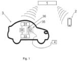
- Figure 1 illustrates in detail the set of elements forming the system which are located inside the vehicle 3 and those that necessarily make up part of the described system, but are found on the outside of the vehicle 3.
- said components can be seen, as well as the arrangement thereof and connection with each other.
- the system for managing an electric charging service in a vehicle 3 has a control unit 1, in communication through wireless means with a vehicle 3 and with a portable electronic device 2.
- the drawing represents a single vehicle 3 and a single portable electronic device 2, but it is understood that the system of the present invention is made up of a plurality of vehicles 3 and a plurality of portable electronic devices 2, all of them in communication with one control unit 1.
- the vehicle 3 comprises a computing unit 31, which has processing means, memory means and connection means with other components of the vehicle 3.
- Said computing unit 31 is in communication with a charging supply means 32, which may be one or more, comprising means arranged and enabled to supply electric power to a consumer 4 of electric charging (external to the vehicle 3).
- Said charge supply 32 is such that it enables the coupling of the consumer 4 to the charging supply means 32, providing electric power to the consumer 4 (external to the vehicle 3), from an electric power storage device 33 of the vehicle 3.
- the computing unit 31 may additionally be in communication with a battery detection means 34, such that the battery detection unit 34 sends a message to the computing unit 31 with information about the amount of electric power stored in a storage device 33 of the vehicle 3, in response to an express request by the computing unit 31.
- the detection unit 34 and the storage device 33 are in communication, preferably by cabling.
- the storage device 33 can be a high-voltage battery or a low-voltage battery of the vehicle 3, and can be the same as the ones responsible for the propulsion thereof or intended for other functions.
- the vehicle 3 has an access door 35 to the charging supply means 32.
- Said access door 35 can be any suitable component for enabling or limiting the access to the charging supply means 32, having, for example, a hinge which enables the folding of said access door 35. It is understood that if an access door 35 to the charging supply means 32 exists, a user external to the vehicle 3 will be able to access the charging supply means 32 only through the access door 35.
- the vehicle 3 can have at least one electric lock 36 of the access door 35 to the charging supply means 32, wherein the electric lock 36 is in communication with the computing unit 31 of the vehicle 3 in order to automatically control the locking/unlocking thereof.
- the computing unit 31 controls the locking or unlocking state of the access door 35, such that the access to the charging supply means 32 by third parties outside of the vehicle 3 will be limited or enabled, respectively.
- the main objective of the present invention is to provide electric power to a consumer 4 outside of the vehicle 3.
- Said consumer 4 has been represented in figure 1 connected to the charging supply means 32 by means of cabling.
- the transmission of electric power can be any kind which enables charging the battery of said consumer 4, such as charging by means of wireless waves.
- the system for managing an electric charging service in a vehicle 3 comprises a portable electronic device 2, represented in figure 1 as a smartphone but being able to be any other device with means of processing and sending information with the control unit 1, which sends a charging service request to the control unit 1.
- a user who wishes to charge a consumer 4 in a vehicle 3 must make a charging service request by means of the portable electronic device 2.
- the control unit 1 determines a vehicle 3, from among the plurality of candidate vehicles, to offer the charging service.
- the control unit 1 is configured to receive a charging service request of a user from the portable electronic device 2 of the user, wherein the charging service request comprises a location and a start time.
- the request can be made from the same portable electronic device 2 that will receive the electric power supply or from a different portable electronic device 2.
- the possibility is foreseen of such a device being a laptop, a tablet, an electric scooter... among others.
- the possibility is recognised of the user establishing in the charging service request both the amount of charging they are requesting and the preferred location where the charging supply is to be performed.
- the second step 200 of the method consists of determining a candidate vehicle 3 to offer the charging service, based on the charging request received.
- the main object pursued by the present invention is that the user can, from any location, request and reserve, in any time slot, an electric power supply point according to their needs; either for the specific location where the user is located or for any location requested by them. This is possible since there are many available vehicles 3 parked on public roads.
- the control unit 1 determines the best candidate to provide the charging service request based on the requirements requested by the user, or that meets those requirements that the user considers as most important, additionally verifying that the vehicle 3 in question can meet said demands.
- the assignment of the candidate vehicle 3 is performed based on the location wherein the user has requested the charging service and the start time of said service.
- the control unit 1 knows both the current location and the future location of the plurality of vehicles 3 which can offer said service. Future location is understood as the location that the vehicle 3 will occupy according to the navigation data and paths that the system has. Specifically, the location of each vehicle 3 is evaluated at the start time of the service. Thus, the candidate vehicle 3 to be selected will be the one closest to the location indicated by the user, at the start time of the service.
- the final charging time is taken into account, in other words, the time when the charging service will end.
- This final time can be expressly indicated by the user in the charging service request, or by calculating the foreseen time when the charging service will end, based on the amount of electric power demanded or to be supplied to the consumer 4.
- a vehicle 3 will be assigned that is closest to the requested location and which remains at the location indicated by the user during the time interval between the start time and the end time, requested or foreseen, of the charging service.
- the amount of electric power to be supplied is taken into account.
- This amount of electric power can be previously established by the user in the charging service request sent or it can be detected automatically by the system of the vehicle 3 itself.
- the user in advance, can request a specific amount of electric power to charge the desired portable electronic device 2, indicating in the charging service request the amount of electric power required.
- the charging service request may additionally comprise an indication that the consumer 4 of electric power is the portable electronic device 2 itself which sends the charging service request, or that the consumer 4 of electric power is any other portable electronic device 2.
- said control unit 1 is capable of automatically calculating in an intuitive, quick and accurate manner the amount of electric power that will be consumed, taking into account values such as amperage, power to be consumed, time slot... among others.
- the control unit 1 allocates, in addition to other parameters mentioned above, the assigned vehicle 3 based on the amount of electric power demanded by the user and the amount of electric power available in the candidate vehicles 3.
- said information about the amount of power to be supplied is sent to the computing unit 31 of the vehicle 3, with the aim of limiting the electric power supplied to the amount of electric power demanded.
- the control unit 1 is configured to assign the candidate vehicle 3 to the charging service request of the user if the result of the comparison of the electric power requested with the electric power stored in the storage device 33 of the vehicle 3 is greater than a predefined value. Additionally, given the existence of more than one candidate vehicle 3 available to supply electric power in the location and time slot required by the user, the control unit 1 will assign the vehicle with the highest electric power stored in the storage device 33.
- the control unit 1 assigns the candidate vehicle 3 to the charging service request of the user. This happens when the candidate vehicle 3 meets all the requirements previously established by the user or when, despite not meeting all of them, it is the user who decides that a specific vehicle 3 be responsible for supplying the electric power demanded.
- the control unit 1 sends to the portable electronic device 2 of the user a plurality of options of candidate vehicles 3 that are suitable for offering the requested charging service, such that it is the user who performs the assignment of the candidate vehicle 3.
- the computing unit 31 of the assigned vehicle 3 and the portable electronic device 2 of the user are paired with each other by means of the control unit 1.
- the control unit 1 will reserve the vehicle 3 assigned to the specific charging service, such that said vehicle 3 will not be able to be assigned for other charging services in the time slot of the charging service for which it has been paired.
- Pairing the computing unit 31 of the vehicle 3 with the portable electronic device 2 of the user is understood as sending a set of confirmation messages to both devices with the aim of, on the one hand, notifying the computing unit 31 about the vehicle 3 that has been allocated to offer a charging service and, on the other hand, notifying the user about the satisfactory assignment of a vehicle 3 which meets the needs of the requested charging service.
- the computing unit 31 of the vehicle will be aware of the start time and other parameters of the charging service demanded, thus being able to know the moment it is activated and/or the amount of electric power to be supplied and/or the amperage demanded, among other parameters.
- pairing the computing unit 31 of the vehicle 3 with the portable electronic device 2 of the user means sending a plurality of unique codes associated with the specific charging service.
- both the vehicle 3 and the portable electronic device 2 will be notified with the codes that enable the unlocking of the electric lock 36 in question, enabling the user to access the charging supply means 32 in order to be able to couple the consumer 4.
- the control unit 1 is configured to generate and send an activation signal of the at least one charging supply means 32 to the computing unit 31 of the assigned vehicle 3.
- This activation signal is generated and sent in response to a start request of the charging service sent by the portable electronic device 2 of the user.
- the control unit 1 will verify that the demand to start the charging service is performed at a time substantially the same as the start time of the service demanded previously. If there is an affirmative verification, the control unit 1 will send a message to the computing unit 31 of the vehicle 3 in order to enable electric power to be sent by means of the charging supply means 32.
- control unit 1 sends a locking/unlocking signal to the computing unit 31 in order to unlock the electric lock 36 of the assigned vehicle 3 when the request to open the access door 35 is sent by the portable electronic device 2 of the user at a time essentially the same as the start time of the charging service request.
- the method has a step 600 wherein the computing unit 31 disables the electric power supply.
- the charging supply means 32 will end the contribution of electric power to the consumer 4.
- Said signal to disable the electric power supply can be sent when the current time is equal to the end time of the charging service demanded, or when the amount of power supplied is equal to the amount of electric power demanded or, in the absence thereof, estimated to completely charge the battery of consumer 4, among others.
- the computing unit 31 is configured to lock the electric lock 36 of the access door 35 of the charging supply means 32 once the charging service has ended.
- both the signal to disable the charging supply means 32 and the signal to lock the electric lock 36 can be notified to the control unit 1 with the aim of informing that the charging service has ended and that the vehicle 3 can be assigned to perform another demanded charging service.
Applications Claiming Priority (1)
| Application Number | Priority Date | Filing Date | Title |
|---|---|---|---|
| ES202030146A ES2849964B2 (es) | 2020-02-21 | 2020-02-21 | Sistema de gestión de un servicio de carga eléctrica en un vehículo y vehículo suministrador de un servicio de carga eléctrica |
Publications (2)
| Publication Number | Publication Date |
|---|---|
| EP3868596A1 EP3868596A1 (en) | 2021-08-25 |
| EP3868596B1 true EP3868596B1 (en) | 2023-09-06 |
Family
ID=74846634
Family Applications (1)
| Application Number | Title | Priority Date | Filing Date |
|---|---|---|---|
| EP21382106.9A Active EP3868596B1 (en) | 2020-02-21 | 2021-02-11 | System for managing an electric charging service in a vehicle and vehicle supplying an electric charging service |
Country Status (3)
| Country | Link |
|---|---|
| EP (1) | EP3868596B1 (es) |
| DE (1) | DE202020107572U1 (es) |
| ES (1) | ES2849964B2 (es) |
Families Citing this family (1)
| Publication number | Priority date | Publication date | Assignee | Title |
|---|---|---|---|---|
| JP7154246B2 (ja) * | 2020-03-13 | 2022-10-17 | 本田技研工業株式会社 | 避難所への配車サービス装置、避難所への配車サービス方法、およびプログラム |
Citations (1)
| Publication number | Priority date | Publication date | Assignee | Title |
|---|---|---|---|---|
| US20180281614A1 (en) * | 2015-12-07 | 2018-10-04 | Hunan Scientop Automatic Equipment Shares Co., Ltd | Charging rescue system and method for all-electric vehicles |
Family Cites Families (9)
| Publication number | Priority date | Publication date | Assignee | Title |
|---|---|---|---|---|
| EP2677607B1 (en) * | 2011-02-15 | 2019-06-19 | Toyota Jidosha Kabushiki Kaisha | Adapter and vehicle equipped therewith, and method for controlling the vehicle |
| CN103493310B (zh) * | 2011-10-17 | 2016-06-29 | 丰田自动车株式会社 | 馈电连接器、车辆以及馈电连接器的识别方法 |
| JP5895472B2 (ja) * | 2011-11-22 | 2016-03-30 | 三菱自動車工業株式会社 | 電力供給車両 |
| KR101654714B1 (ko) * | 2015-06-02 | 2016-09-07 | 하충목 | 스마트폰을 이용한 전기자동차 양방향 충전 관리시스템 및 방법 |
| US10383156B2 (en) * | 2015-11-19 | 2019-08-13 | GM Global Technology Operations LLC | Operating a mobile hotspot at a vehicle |
| KR101736116B1 (ko) * | 2016-03-22 | 2017-05-29 | 현대자동차주식회사 | 차량, 차량 제어 시스템, 차량용 표시 장치, 단말 장치 및 차량의 제어 방법 |
| JP6597592B2 (ja) * | 2016-12-26 | 2019-10-30 | トヨタ自動車株式会社 | 電動車両 |
| US10312721B2 (en) * | 2017-06-06 | 2019-06-04 | Ford Global Technologies, Llc | Vehicle unlocking systems devices and methods |
| CN110316013B (zh) * | 2018-03-29 | 2022-09-27 | 睿能创意公司 | 载具、载具充电系统以及载具充电方法 |
-
2020
- 2020-02-21 ES ES202030146A patent/ES2849964B2/es not_active Expired - Fee Related
- 2020-12-28 DE DE202020107572.1U patent/DE202020107572U1/de active Active
-
2021
- 2021-02-11 EP EP21382106.9A patent/EP3868596B1/en active Active
Patent Citations (1)
| Publication number | Priority date | Publication date | Assignee | Title |
|---|---|---|---|---|
| US20180281614A1 (en) * | 2015-12-07 | 2018-10-04 | Hunan Scientop Automatic Equipment Shares Co., Ltd | Charging rescue system and method for all-electric vehicles |
Also Published As
| Publication number | Publication date |
|---|---|
| ES2849964B2 (es) | 2022-11-17 |
| ES2849964A1 (es) | 2021-08-24 |
| EP3868596A1 (en) | 2021-08-25 |
| DE202020107572U1 (de) | 2021-02-16 |
Similar Documents
| Publication | Publication Date | Title |
|---|---|---|
| US10926652B2 (en) | Method for automatic unlocking of a charging arrangement and motor vehicle | |
| US10442300B2 (en) | Vehicle communications, power management, and seating systems | |
| CN109726888A (zh) | 配车系统以及配车方法 | |
| US10150380B2 (en) | Dynamic allocation of power modules for charging electric vehicles | |
| KR102564648B1 (ko) | 차량 원격 제어 시스템, 통신 모듈, 차량, 서버, 차량 원격 제어 방법, 차량 원격 제어 프로그램 및 기억 매체 | |
| EP2109203B1 (en) | Battery charging system for electric vehicle | |
| US10521987B1 (en) | Enhanced electrified vehicle charger security | |
| US20170004712A1 (en) | Regional electric vehicle sharing and management system and method | |
| JP5773062B2 (ja) | 車両共同利用システム及び車両共同利用方法 | |
| CN110139776A (zh) | 充电系统和程序 | |
| CN107924531B (zh) | 车辆管理方法和车辆管理装置 | |
| US20160144726A1 (en) | Vehicular wireless power feeding system, vehicle-side power feeding system and portable apparatus | |
| EP3868596B1 (en) | System for managing an electric charging service in a vehicle and vehicle supplying an electric charging service | |
| TWI565610B (zh) | 充電站系統與相關電動車充電方法 | |
| US20220245234A1 (en) | Systems and methods for managing batteries | |
| US11161427B2 (en) | Management server, information processing method, and information processing system | |
| CN113453948A (zh) | 用于通知交通工具的使用者的方法、控制装置和交通工具 | |
| CN113628368B (zh) | 一种充电站的控制方法、装置和设备 | |
| KR102186878B1 (ko) | 충전용 콘센트 장치 | |
| CN114205747A (zh) | 无人驾驶车辆的乘车方法、装置、设备、存储介质及终端 | |
| KR20220120163A (ko) | 이동형 전기차 충전 서비스 방법 | |
| CN111497779A (zh) | 汽车电子钥匙控制装置、汽车电子钥匙控制方法及系统 | |
| US10682917B2 (en) | Method and system for releasing a power supply line to supply power to a vehicle | |
| CN113498056B (zh) | 激活机动车充电过程的方法和系统以及服务器装置 | |
| KR101252965B1 (ko) | 전기자동차용 충전 장치 및 전기자동차의 제어 방법 |
Legal Events
| Date | Code | Title | Description |
|---|---|---|---|
| PUAI | Public reference made under article 153(3) epc to a published international application that has entered the european phase |
Free format text: ORIGINAL CODE: 0009012 |
|
| STAA | Information on the status of an ep patent application or granted ep patent |
Free format text: STATUS: THE APPLICATION HAS BEEN PUBLISHED |
|
| AK | Designated contracting states |
Kind code of ref document: A1 Designated state(s): AL AT BE BG CH CY CZ DE DK EE ES FI FR GB GR HR HU IE IS IT LI LT LU LV MC MK MT NL NO PL PT RO RS SE SI SK SM TR |
|
| STAA | Information on the status of an ep patent application or granted ep patent |
Free format text: STATUS: REQUEST FOR EXAMINATION WAS MADE |
|
| 17P | Request for examination filed |
Effective date: 20220217 |
|
| RBV | Designated contracting states (corrected) |
Designated state(s): AL AT BE BG CH CY CZ DE DK EE ES FI FR GB GR HR HU IE IS IT LI LT LU LV MC MK MT NL NO PL PT RO RS SE SI SK SM TR |
|
| RIC1 | Information provided on ipc code assigned before grant |
Ipc: B60L 1/00 20060101AFI20230224BHEP |
|
| GRAP | Despatch of communication of intention to grant a patent |
Free format text: ORIGINAL CODE: EPIDOSNIGR1 |
|
| STAA | Information on the status of an ep patent application or granted ep patent |
Free format text: STATUS: GRANT OF PATENT IS INTENDED |
|
| INTG | Intention to grant announced |
Effective date: 20230418 |
|
| P01 | Opt-out of the competence of the unified patent court (upc) registered |
Effective date: 20230527 |
|
| GRAS | Grant fee paid |
Free format text: ORIGINAL CODE: EPIDOSNIGR3 |
|
| GRAA | (expected) grant |
Free format text: ORIGINAL CODE: 0009210 |
|
| STAA | Information on the status of an ep patent application or granted ep patent |
Free format text: STATUS: THE PATENT HAS BEEN GRANTED |
|
| AK | Designated contracting states |
Kind code of ref document: B1 Designated state(s): AL AT BE BG CH CY CZ DE DK EE ES FI FR GB GR HR HU IE IS IT LI LT LU LV MC MK MT NL NO PL PT RO RS SE SI SK SM TR |
|
| REG | Reference to a national code |
Ref country code: GB Ref legal event code: FG4D |
|
| REG | Reference to a national code |
Ref country code: CH Ref legal event code: EP |
|
| REG | Reference to a national code |
Ref country code: IE Ref legal event code: FG4D |
|
| REG | Reference to a national code |
Ref country code: DE Ref legal event code: R096 Ref document number: 602021004962 Country of ref document: DE |
|
| REG | Reference to a national code |
Ref country code: LT Ref legal event code: MG9D |
|
| REG | Reference to a national code |
Ref country code: NL Ref legal event code: MP Effective date: 20230906 |
|
| PG25 | Lapsed in a contracting state [announced via postgrant information from national office to epo] |
Ref country code: GR Free format text: LAPSE BECAUSE OF FAILURE TO SUBMIT A TRANSLATION OF THE DESCRIPTION OR TO PAY THE FEE WITHIN THE PRESCRIBED TIME-LIMIT Effective date: 20231207 |
|
| PG25 | Lapsed in a contracting state [announced via postgrant information from national office to epo] |
Ref country code: SE Free format text: LAPSE BECAUSE OF FAILURE TO SUBMIT A TRANSLATION OF THE DESCRIPTION OR TO PAY THE FEE WITHIN THE PRESCRIBED TIME-LIMIT Effective date: 20230906 Ref country code: RS Free format text: LAPSE BECAUSE OF FAILURE TO SUBMIT A TRANSLATION OF THE DESCRIPTION OR TO PAY THE FEE WITHIN THE PRESCRIBED TIME-LIMIT Effective date: 20230906 Ref country code: NO Free format text: LAPSE BECAUSE OF FAILURE TO SUBMIT A TRANSLATION OF THE DESCRIPTION OR TO PAY THE FEE WITHIN THE PRESCRIBED TIME-LIMIT Effective date: 20231206 Ref country code: LV Free format text: LAPSE BECAUSE OF FAILURE TO SUBMIT A TRANSLATION OF THE DESCRIPTION OR TO PAY THE FEE WITHIN THE PRESCRIBED TIME-LIMIT Effective date: 20230906 Ref country code: LT Free format text: LAPSE BECAUSE OF FAILURE TO SUBMIT A TRANSLATION OF THE DESCRIPTION OR TO PAY THE FEE WITHIN THE PRESCRIBED TIME-LIMIT Effective date: 20230906 Ref country code: HR Free format text: LAPSE BECAUSE OF FAILURE TO SUBMIT A TRANSLATION OF THE DESCRIPTION OR TO PAY THE FEE WITHIN THE PRESCRIBED TIME-LIMIT Effective date: 20230906 Ref country code: GR Free format text: LAPSE BECAUSE OF FAILURE TO SUBMIT A TRANSLATION OF THE DESCRIPTION OR TO PAY THE FEE WITHIN THE PRESCRIBED TIME-LIMIT Effective date: 20231207 Ref country code: FI Free format text: LAPSE BECAUSE OF FAILURE TO SUBMIT A TRANSLATION OF THE DESCRIPTION OR TO PAY THE FEE WITHIN THE PRESCRIBED TIME-LIMIT Effective date: 20230906 |
|
| REG | Reference to a national code |
Ref country code: AT Ref legal event code: MK05 Ref document number: 1608111 Country of ref document: AT Kind code of ref document: T Effective date: 20230906 |
|
| PG25 | Lapsed in a contracting state [announced via postgrant information from national office to epo] |
Ref country code: NL Free format text: LAPSE BECAUSE OF FAILURE TO SUBMIT A TRANSLATION OF THE DESCRIPTION OR TO PAY THE FEE WITHIN THE PRESCRIBED TIME-LIMIT Effective date: 20230906 |
|
| PG25 | Lapsed in a contracting state [announced via postgrant information from national office to epo] |
Ref country code: IS Free format text: LAPSE BECAUSE OF FAILURE TO SUBMIT A TRANSLATION OF THE DESCRIPTION OR TO PAY THE FEE WITHIN THE PRESCRIBED TIME-LIMIT Effective date: 20240106 |
|
| PG25 | Lapsed in a contracting state [announced via postgrant information from national office to epo] |
Ref country code: AT Free format text: LAPSE BECAUSE OF FAILURE TO SUBMIT A TRANSLATION OF THE DESCRIPTION OR TO PAY THE FEE WITHIN THE PRESCRIBED TIME-LIMIT Effective date: 20230906 |
|
| PG25 | Lapsed in a contracting state [announced via postgrant information from national office to epo] |
Ref country code: ES Free format text: LAPSE BECAUSE OF FAILURE TO SUBMIT A TRANSLATION OF THE DESCRIPTION OR TO PAY THE FEE WITHIN THE PRESCRIBED TIME-LIMIT Effective date: 20230906 |
|
| PG25 | Lapsed in a contracting state [announced via postgrant information from national office to epo] |
Ref country code: SM Free format text: LAPSE BECAUSE OF FAILURE TO SUBMIT A TRANSLATION OF THE DESCRIPTION OR TO PAY THE FEE WITHIN THE PRESCRIBED TIME-LIMIT Effective date: 20230906 Ref country code: RO Free format text: LAPSE BECAUSE OF FAILURE TO SUBMIT A TRANSLATION OF THE DESCRIPTION OR TO PAY THE FEE WITHIN THE PRESCRIBED TIME-LIMIT Effective date: 20230906 Ref country code: IS Free format text: LAPSE BECAUSE OF FAILURE TO SUBMIT A TRANSLATION OF THE DESCRIPTION OR TO PAY THE FEE WITHIN THE PRESCRIBED TIME-LIMIT Effective date: 20240106 Ref country code: ES Free format text: LAPSE BECAUSE OF FAILURE TO SUBMIT A TRANSLATION OF THE DESCRIPTION OR TO PAY THE FEE WITHIN THE PRESCRIBED TIME-LIMIT Effective date: 20230906 Ref country code: EE Free format text: LAPSE BECAUSE OF FAILURE TO SUBMIT A TRANSLATION OF THE DESCRIPTION OR TO PAY THE FEE WITHIN THE PRESCRIBED TIME-LIMIT Effective date: 20230906 Ref country code: CZ Free format text: LAPSE BECAUSE OF FAILURE TO SUBMIT A TRANSLATION OF THE DESCRIPTION OR TO PAY THE FEE WITHIN THE PRESCRIBED TIME-LIMIT Effective date: 20230906 Ref country code: AT Free format text: LAPSE BECAUSE OF FAILURE TO SUBMIT A TRANSLATION OF THE DESCRIPTION OR TO PAY THE FEE WITHIN THE PRESCRIBED TIME-LIMIT Effective date: 20230906 Ref country code: PT Free format text: LAPSE BECAUSE OF FAILURE TO SUBMIT A TRANSLATION OF THE DESCRIPTION OR TO PAY THE FEE WITHIN THE PRESCRIBED TIME-LIMIT Effective date: 20240108 Ref country code: SK Free format text: LAPSE BECAUSE OF FAILURE TO SUBMIT A TRANSLATION OF THE DESCRIPTION OR TO PAY THE FEE WITHIN THE PRESCRIBED TIME-LIMIT Effective date: 20230906 |
|
| PGFP | Annual fee paid to national office [announced via postgrant information from national office to epo] |
Ref country code: DE Payment date: 20240228 Year of fee payment: 4 |