EP3867711B1 - Wickelmaschine mit einem auswertesystem für das zu verarbeitende bahnmaterial und verfahren - Google Patents
Wickelmaschine mit einem auswertesystem für das zu verarbeitende bahnmaterial und verfahren Download PDFInfo
- Publication number
- EP3867711B1 EP3867711B1 EP19798398.4A EP19798398A EP3867711B1 EP 3867711 B1 EP3867711 B1 EP 3867711B1 EP 19798398 A EP19798398 A EP 19798398A EP 3867711 B1 EP3867711 B1 EP 3867711B1
- Authority
- EP
- European Patent Office
- Prior art keywords
- web material
- winding
- strips
- feeding
- width
- Prior art date
- Legal status (The legal status is an assumption and is not a legal conclusion. Google has not performed a legal analysis and makes no representation as to the accuracy of the status listed.)
- Active
Links
- 239000000463 material Substances 0.000 title claims description 409
- 238000004804 winding Methods 0.000 title claims description 204
- 238000011156 evaluation Methods 0.000 title claims description 44
- 238000000034 method Methods 0.000 title claims description 40
- 238000005520 cutting process Methods 0.000 claims description 78
- 238000011144 upstream manufacturing Methods 0.000 claims description 25
- 230000008602 contraction Effects 0.000 claims description 12
- 238000012545 processing Methods 0.000 claims description 11
- 239000002184 metal Substances 0.000 claims description 10
- 238000001514 detection method Methods 0.000 claims description 5
- 230000007547 defect Effects 0.000 description 33
- 238000004519 manufacturing process Methods 0.000 description 26
- 230000002093 peripheral effect Effects 0.000 description 14
- 239000004745 nonwoven fabric Substances 0.000 description 13
- 239000000047 product Substances 0.000 description 12
- 230000001276 controlling effect Effects 0.000 description 11
- 238000005259 measurement Methods 0.000 description 11
- 230000000694 effects Effects 0.000 description 8
- 230000008569 process Effects 0.000 description 8
- 238000010586 diagram Methods 0.000 description 7
- 241000234295 Musa Species 0.000 description 5
- 235000018290 Musa x paradisiaca Nutrition 0.000 description 5
- 230000000875 corresponding effect Effects 0.000 description 5
- 238000012360 testing method Methods 0.000 description 5
- 241000196324 Embryophyta Species 0.000 description 4
- 101001002709 Homo sapiens Interleukin-4 Proteins 0.000 description 4
- 101001076408 Homo sapiens Interleukin-6 Proteins 0.000 description 4
- 102100020941 Interleukin-4 Human genes 0.000 description 4
- 102100026019 Interleukin-6 Human genes 0.000 description 4
- 238000009826 distribution Methods 0.000 description 4
- 230000033001 locomotion Effects 0.000 description 4
- 238000013459 approach Methods 0.000 description 3
- 230000005540 biological transmission Effects 0.000 description 3
- 230000015572 biosynthetic process Effects 0.000 description 3
- 230000008859 change Effects 0.000 description 3
- 239000013256 coordination polymer Substances 0.000 description 3
- 230000003287 optical effect Effects 0.000 description 3
- 230000007480 spreading Effects 0.000 description 3
- 238000003892 spreading Methods 0.000 description 3
- 241000238631 Hexapoda Species 0.000 description 2
- 230000004323 axial length Effects 0.000 description 2
- 230000002596 correlated effect Effects 0.000 description 2
- 230000001066 destructive effect Effects 0.000 description 2
- 238000006073 displacement reaction Methods 0.000 description 2
- 238000009432 framing Methods 0.000 description 2
- 239000003292 glue Substances 0.000 description 2
- 230000004807 localization Effects 0.000 description 2
- 239000011159 matrix material Substances 0.000 description 2
- 239000002994 raw material Substances 0.000 description 2
- 239000011265 semifinished product Substances 0.000 description 2
- 206010021639 Incontinence Diseases 0.000 description 1
- 230000001133 acceleration Effects 0.000 description 1
- 238000003491 array Methods 0.000 description 1
- 230000033228 biological regulation Effects 0.000 description 1
- 238000003490 calendering Methods 0.000 description 1
- 238000011109 contamination Methods 0.000 description 1
- 230000001419 dependent effect Effects 0.000 description 1
- 239000000835 fiber Substances 0.000 description 1
- 239000012467 final product Substances 0.000 description 1
- ZZUFCTLCJUWOSV-UHFFFAOYSA-N furosemide Chemical compound C1=C(Cl)C(S(=O)(=O)N)=CC(C(O)=O)=C1NCC1=CC=CO1 ZZUFCTLCJUWOSV-UHFFFAOYSA-N 0.000 description 1
- 230000005484 gravity Effects 0.000 description 1
- 230000012010 growth Effects 0.000 description 1
- 230000001939 inductive effect Effects 0.000 description 1
- 238000012423 maintenance Methods 0.000 description 1
- 230000007257 malfunction Effects 0.000 description 1
- 230000009347 mechanical transmission Effects 0.000 description 1
- 239000002923 metal particle Substances 0.000 description 1
- 238000012986 modification Methods 0.000 description 1
- 230000004048 modification Effects 0.000 description 1
- 238000011017 operating method Methods 0.000 description 1
- 230000010355 oscillation Effects 0.000 description 1
- 238000004806 packaging method and process Methods 0.000 description 1
- 239000004033 plastic Substances 0.000 description 1
- 239000002985 plastic film Substances 0.000 description 1
- 229920006255 plastic film Polymers 0.000 description 1
- 238000003908 quality control method Methods 0.000 description 1
- 238000004064 recycling Methods 0.000 description 1
- 230000009467 reduction Effects 0.000 description 1
- 238000009966 trimming Methods 0.000 description 1
- 230000000007 visual effect Effects 0.000 description 1
- 239000002699 waste material Substances 0.000 description 1
- 230000037303 wrinkles Effects 0.000 description 1
Images


Classifications
-
- B—PERFORMING OPERATIONS; TRANSPORTING
- B26—HAND CUTTING TOOLS; CUTTING; SEVERING
- B26D—CUTTING; DETAILS COMMON TO MACHINES FOR PERFORATING, PUNCHING, CUTTING-OUT, STAMPING-OUT OR SEVERING
- B26D7/00—Details of apparatus for cutting, cutting-out, stamping-out, punching, perforating, or severing by means other than cutting
- B26D7/26—Means for mounting or adjusting the cutting member; Means for adjusting the stroke of the cutting member
- B26D7/2614—Means for mounting the cutting member
- B26D7/2621—Means for mounting the cutting member for circular cutters
-
- B—PERFORMING OPERATIONS; TRANSPORTING
- B65—CONVEYING; PACKING; STORING; HANDLING THIN OR FILAMENTARY MATERIAL
- B65H—HANDLING THIN OR FILAMENTARY MATERIAL, e.g. SHEETS, WEBS, CABLES
- B65H23/00—Registering, tensioning, smoothing or guiding webs
- B65H23/04—Registering, tensioning, smoothing or guiding webs longitudinally
- B65H23/18—Registering, tensioning, smoothing or guiding webs longitudinally by controlling or regulating the web-advancing mechanism, e.g. mechanism acting on the running web
- B65H23/182—Registering, tensioning, smoothing or guiding webs longitudinally by controlling or regulating the web-advancing mechanism, e.g. mechanism acting on the running web in unwinding mechanisms or in connection with unwinding operations
- B65H23/1825—Registering, tensioning, smoothing or guiding webs longitudinally by controlling or regulating the web-advancing mechanism, e.g. mechanism acting on the running web in unwinding mechanisms or in connection with unwinding operations and controlling web tension
-
- B—PERFORMING OPERATIONS; TRANSPORTING
- B65—CONVEYING; PACKING; STORING; HANDLING THIN OR FILAMENTARY MATERIAL
- B65H—HANDLING THIN OR FILAMENTARY MATERIAL, e.g. SHEETS, WEBS, CABLES
- B65H23/00—Registering, tensioning, smoothing or guiding webs
- B65H23/04—Registering, tensioning, smoothing or guiding webs longitudinally
- B65H23/18—Registering, tensioning, smoothing or guiding webs longitudinally by controlling or regulating the web-advancing mechanism, e.g. mechanism acting on the running web
- B65H23/195—Registering, tensioning, smoothing or guiding webs longitudinally by controlling or regulating the web-advancing mechanism, e.g. mechanism acting on the running web in winding mechanisms or in connection with winding operations
- B65H23/1955—Registering, tensioning, smoothing or guiding webs longitudinally by controlling or regulating the web-advancing mechanism, e.g. mechanism acting on the running web in winding mechanisms or in connection with winding operations and controlling web tension
-
- B—PERFORMING OPERATIONS; TRANSPORTING
- B26—HAND CUTTING TOOLS; CUTTING; SEVERING
- B26D—CUTTING; DETAILS COMMON TO MACHINES FOR PERFORATING, PUNCHING, CUTTING-OUT, STAMPING-OUT OR SEVERING
- B26D7/00—Details of apparatus for cutting, cutting-out, stamping-out, punching, perforating, or severing by means other than cutting
- B26D7/26—Means for mounting or adjusting the cutting member; Means for adjusting the stroke of the cutting member
- B26D7/2628—Means for adjusting the position of the cutting member
- B26D7/2635—Means for adjusting the position of the cutting member for circular cutters
-
- B—PERFORMING OPERATIONS; TRANSPORTING
- B65—CONVEYING; PACKING; STORING; HANDLING THIN OR FILAMENTARY MATERIAL
- B65H—HANDLING THIN OR FILAMENTARY MATERIAL, e.g. SHEETS, WEBS, CABLES
- B65H2220/00—Function indicators
- B65H2220/09—Function indicators indicating that several of an entity are present
-
- B—PERFORMING OPERATIONS; TRANSPORTING
- B65—CONVEYING; PACKING; STORING; HANDLING THIN OR FILAMENTARY MATERIAL
- B65H—HANDLING THIN OR FILAMENTARY MATERIAL, e.g. SHEETS, WEBS, CABLES
- B65H2301/00—Handling processes for sheets or webs
- B65H2301/40—Type of handling process
- B65H2301/41—Winding, unwinding
- B65H2301/414—Winding
- B65H2301/4148—Winding slitting
-
- B—PERFORMING OPERATIONS; TRANSPORTING
- B65—CONVEYING; PACKING; STORING; HANDLING THIN OR FILAMENTARY MATERIAL
- B65H—HANDLING THIN OR FILAMENTARY MATERIAL, e.g. SHEETS, WEBS, CABLES
- B65H2511/00—Dimensions; Position; Numbers; Identification; Occurrences
- B65H2511/20—Location in space
- B65H2511/22—Distance
-
- B—PERFORMING OPERATIONS; TRANSPORTING
- B65—CONVEYING; PACKING; STORING; HANDLING THIN OR FILAMENTARY MATERIAL
- B65H—HANDLING THIN OR FILAMENTARY MATERIAL, e.g. SHEETS, WEBS, CABLES
- B65H2511/00—Dimensions; Position; Numbers; Identification; Occurrences
- B65H2511/40—Identification
- B65H2511/413—Identification of image
-
- B—PERFORMING OPERATIONS; TRANSPORTING
- B65—CONVEYING; PACKING; STORING; HANDLING THIN OR FILAMENTARY MATERIAL
- B65H—HANDLING THIN OR FILAMENTARY MATERIAL, e.g. SHEETS, WEBS, CABLES
- B65H2801/00—Application field
- B65H2801/57—Diaper manufacture
-
- G—PHYSICS
- G05—CONTROLLING; REGULATING
- G05B—CONTROL OR REGULATING SYSTEMS IN GENERAL; FUNCTIONAL ELEMENTS OF SUCH SYSTEMS; MONITORING OR TESTING ARRANGEMENTS FOR SUCH SYSTEMS OR ELEMENTS
- G05B19/00—Programme-control systems
- G05B19/02—Programme-control systems electric
- G05B19/18—Numerical control [NC], i.e. automatically operating machines, in particular machine tools, e.g. in a manufacturing environment, so as to execute positioning, movement or co-ordinated operations by means of programme data in numerical form
- G05B19/19—Numerical control [NC], i.e. automatically operating machines, in particular machine tools, e.g. in a manufacturing environment, so as to execute positioning, movement or co-ordinated operations by means of programme data in numerical form characterised by positioning or contouring control systems, e.g. to control position from one programmed point to another or to control movement along a programmed continuous path
- G05B19/195—Controlling the position of several slides on one axis
Definitions
- the present invention relates to improvements to the winding machines, in particular to winders or rewinders provided with cutting members which slit the fed web material into longitudinal strips to produce in parallel a plurality of reels of wound material having axial dimension smaller than the width of the web material entering the machine.
- embodiments disclosed herein relate to so-called slitter-rewinders.
- the invention relates to improvements to rewinding or winding machines which cut a web material coming from a primary reel or a production machine, slitting it into a plurality of longitudinal strips wound into secondary reels.
- the invention also relates to improvements to the methods for winding or rewinding a web material, coming from a primary reel or a production machine, into secondary reels, each formed by a respective strip into which the web material from the primary reel has been slit.
- web materials are produced, i.e. thin materials, which are wound into primary reels, also called parent reels or master rolls.
- primary reels also called parent reels or master rolls.
- the web material of the primary reels is unwound and rewound into reels or rolls of smaller diameter by means of rewinding processes and methods.
- the web material is also slit into a plurality of adjacent longitudinal strips by means of a cutting device comprising a plurality of blades or knives, typically of discoid shape.
- the rewinder directly forms reels of small axial dimension.
- the rewinders comprising, to this end, longitudinal cutting devices are also referred to as slitter-rewinders or rewinder-slitters. Embodiments disclosed below relate to this type of machines.
- the primary reels can be formed by machines called “winders” or “winding machines”, fed by a web material forming line.
- vision systems and/or metal detectors installed at the end of the non-woven production line, before the winder. These systems control the quality of the formed web material before it is wound into primary reels.
- these vision systems or metal detectors give information on the presence of: holes; fiber lumps; plastic molten in the web material; insects trapped in the web material; oil stains; dirt stains; creases; tears; metal contamination; material other than the raw material; production quality of the web material (thickness uniformity).
- the vision systems together with a measurement system in machine direction, i.e. in the web material feeding direction, installed on the winder, generate a map of defects in the primary reel, indicating, for each defect, the coordinates thereof in machine direction (MD) and cross direction (CD).
- MD machine direction
- CD cross direction
- the known systems do not allow for the detection of some characteristics of the web material resulting from mechanical actions (cutting, traction, rewinding) performed after winding into primary reels.
- one of the features of the rewinder is to wind secondary reels comprised of strips of constant width and with end surfaces as flat as possible. This is required by the user of the secondary reels as, during the following working steps (converting) it is necessary to have available reels with a strip of constant width and with the edges of the strip remaining always in the same position also when the diameter of the reel being unwound changes.
- the strip width mainly depends on the mechanical features of the web material and on the tension thereof in the point of longitudinal cut and in the point of winding of the rewinder.
- a rewinding machine for winding a web material into a plurality of secondary reels according to claim 1, comprising a winding station, with a winding cradle adapted to receive secondary winding cores that are adjacent to, and coaxial with, one another.
- the term "rewinder” refers to a machine receiving a continuous web material and winding it into a plurality of reels.
- a rewinding machine can be a machine receiving a continuous web material from a primary reel and rewinding it into secondary reels, after having cut it into longitudinal strips.
- the winding machine or rewinding machine comprises a cutting device with a plurality of blades, which is arranged upstream of the winding cradle with respect to the web material feeding direction.
- the cutting device is adapted to cut the web material entering the machine into a plurality of strips of web material, each of which will form a respective secondary reel.
- the winder or rewinder also comprises an evaluation system for evaluating the web material.
- the evaluation system is arranged along the feeding path of the web material coming from a primary reel and supplied to the winding cradle.
- web material evaluation system refers to any system adapted to detect or to acquire one or more qualitative or quantitative features of the web material, before or, preferably after the web material has been divided into longitudinal strips by means of the cutting device.
- features of the web material may refer, in general, to structural and material features, including defects of the web material, such as stains, tears, holes, creases, lumps, foreign materials, changes in thickness, etc..
- features of the material may also refer to dimensional features of the web material, in particular width in cross direction, i.e. orthogonally to the feeding direction, of the web material and/or of the strips, into which it has been subdivided.
- features of the material may also refer to positional features, in particular relative or absolute position of the longitudinal edges of the web material or of the strips, into which is has been divided, with respect to the winding members. Knowing these features, and, if necessary, correcting them during the winding step, may be useful to increase the quality of the produced secondary reels.
- the winding cradle may comprise peripheral winding members.
- Peripheral winding members refer to motorized members, such as roller, belts or a combination thereof, transmitting a rotation torque to the secondary reels being formed in the winding cradle by the effect of the surface friction between the cylindrical surface of the secondary reels and the winding member.
- the winding cradle can also comprise central winding members, i.e. members transmitting the winding motion through a shaft or rod or a pair of tailstocks engaging the tubular winding cores and/or winding rods or shafts, on which the tubular winding cores are locked.
- the winding cradle may comprise a combination of peripheral winding members and central winding members.
- the winding cradle comprises a pair of motorized winding rollers, adjacent to each other, whose respective rotation axes lie on a preferably horizontal plane.
- the tubular winding cores rest in the nip defined between the two winding rollers.
- the strips of web material to be wound onto the single winding core are driven around one of said winding rollers.
- the web material evaluation system may comprise a system for capturing images of the web material, for example a video system comprising one or more video cameras for capturing images of the moving web material in fast sequence.
- the images may be processed to acquire information on defects of various kind or other features in the web material, such as creases, tears, holes, presence of foreign material, etc..
- the video cameras may be arranged in fixed position with respect to a stationary structure of the winder or rewinder, and may be of such a number and/or range to capture an image of the whole width of the web material.
- the video cameras can be based on the reflection or transmission system, as described below with reference to some embodiments.
- the images acquired by the video cameras may be also used for determining the width of the web material and/or of the strips, into which it has been divided, or the position of the longitudinal edges of the strips, for purposes that will be explained below.
- the position of the edges of the strips and/or the cross dimensions of the strips or of the web material before it has been divided into strips, may be acquired also by means of systems other than video cameras, as it will be explained below.
- video cameras based on the reflection system can be particularly advantageous.
- the video camera and the respective lighting system for lighting the web material framed by the video camera are arranged on the same side of the web material feeding path.
- the video camera may be arranged so as to take images of the web material in an area where it rests on a guide roller or a guide plate, or on a winding roller, for example.
- the web material is not subjected to oscillations or waving due to aerodynamic effects that could make it difficult to take and/or to process images in order to acquire useful information.
- the web material evaluation system comprises a system adapted to detect the width of at least one portion (e.g. one strip) of the web material.
- the system adapted to detect the width of at least one portion of the web material may use one or more video cameras (based on transmission and/or reflection system), framing the web material in a point of the feeding path thereof.
- the system for detecting the width of the web material may be based on acquisition apparatuses other than the vision systems, as described below in greater details.
- a camera can be provided in a given position of the web material feeding path, framing the whole width of the web material.
- a linear matrix of cameras can be provided, all aligned along the cross direction with respect to the feeding path.
- cameras can be for example used with a limited range (for instance: 1/20 of the whole width of the web material), and the camera(s) can be provided with a cross motion with respect to the web material feeding direction, if this is compatible with the type of information to be acquired.
- an encoder or other system can be associated therewith for detecting the absolute cross position thereof, i.e. the position relative to the fixed structure of the rewinder, so that the programmable control unit receiving the images taken by the camera is also able to associate each image to a given cross position with respect to the width of the web material.
- a laser photocell for detecting the width of the web material or of a portion thereof, for example one or more longitudinal strips into which the web material has been cut, a laser photocell may be provided, adapted to read the presence of the web material, mounted on a linear actuator provided with a system for detecting the achieved position, adapted to transport the photocell in cross direction. This photocell gives an on-off signal based on the presence or absence of the web material in the position in which the photocell is located.
- the system adapted to detect the width of the web material may comprise a laser scanner for reading the whole width of the web material and then outputting data on the width of the strips of web material and on the reciprocal distance therebetween.
- the width of the web material or of a portion thereof can be determined also by means of a device emitting electrostatic charges, arranged on a side of the web material feeding path, together with a grounding system, installed on the opposite side of the web material feeding path, in front of the electrostatic charges emitting device.
- the web material evaluation system is arranged in an area of the web material feeding path comprised between the cutting device and the winding cradle. In this way it is possible to evaluate one or more features of the web material after it has been cut into longitudinal strips. It is also possible to obtain information on each individual strip and, therefore, on each individual secondary reel formed by means of the winder or rewinder. In particular, it is possible to identify any defects in the web material caused by cutting. Furthermore, by arranging the web material evaluation system downstream of the cutting device it is possible to detect with greater precision the position of singularities, defects or generic features of the web material in one or the other of a plurality of secondary reels produced with a web material coming from a single primary reel.
- the web material evaluation system in an area of the feeding path comprised between a winding roller of the winding cradle and a guide roller located directly upstream of the winding roller.
- directly upstream means that between the guide roller and the winding roller there are no further mechanical members, which could modify one or more features of the web material, such as the longitudinal tension, or which could introduce defects in the web material. In this way the information acquired is exactly that of the web material as it is wound into the respective secondary reel.
- the web material evaluation system comprises an arrangement for measuring the Poisson's ratio of the web material.
- the Poisson's ratio, or ratio of transverse strain is a temperature-dependent coefficient that measures the transverse expansion and contraction of a material subjected to a longitudinal unidirectional stress.
- the Poisson's ratio measurement arrangement may comprise, in combination: a first measurement device for measuring a first feeding speed of the web material in a first position along the feeding path of the web material towards the winding cradle; a second measurement device for measuring a second feeding speed of the web material in a second position along the feeding path of the web material towards the winding cradle, downstream of the first position of the feeding path; a first device for acquiring information on a first width of the web material in the first position; a second device for acquiring information on a second width of the web material in the second position.
- Knowing the Poisson's ratio of the web material can be useful for many reasons. Firstly, it is a piece of information that could be useful to provide to those who will use the reels for processing them and producing finished or semi-finished products. Knowing the Poisson's ratio can be useful, for example, to adjust the operating parameters of the reel converting lines. Furthermore, in some cases it may be useful to know the Poisson's ratio of the web material in order to modify, control or manage upstream production parameters. This can be useful, for example, for keeping the Poisson's ratio in a desired range of values, thus ensuring constant quality of the product exiting the production machine. By measuring the actual Poisson's ratio, it is possible to act on one or more upstream production parameters, for example in order to reduce or eliminate an error between the measured Poisson's ratio value and the set value.
- the winder or rewinder comprises a programmable unit, for example a PLC, a micro-controller, a computer or any other device provided with processing means and adapted to modulate one or more parameters of at least one web material feeding member, and in particular of a plurality of web material feeding members arranged in sequence along the feeding path.
- the parameter may be correlated to the feeding speed, for example it may be constituted by the rotation speed of a roller around which the web material is driven, or by means of which it is wound, or by the speed of a winding belt. By adjusting the speed of these members it is possible to adjust the tension of the web material.
- the web material tension can be an important parameter, affecting the quality of the second reel and the behavior thereof during the unwinding step and the subsequent converting into finished products.
- the tension i.e. the longitudinal traction of the web material (both before and after cutting into strips) causes a transverse contraction of the web material and, thus a change in the width thereof.
- the web material evaluation system may be adapted to detect the width of one or more strips of web material and/or of the web material before it has been longitudinally cut.
- the web material evaluation system According to a position of at least one longitudinal edge of the web material, detected by the web material evaluation system, it is possible to determine the contraction of the web material and thus to modify an operating parameter, for example the speed, of one or more feeding members, in order to modulate the tension, and thus the side contraction, of the web material or a portion thereof (strip). In this way, as it will be described in greater detail below, it is for example possible to improve the quality of the secondary reels, obtaining flat head surfaces or at least to reduce the flatness errors thereof, i.e. the deviation of the actual surface from a perfectly flat theoretical surface.
- an operating parameter for example the speed, of one or more feeding members
- a feeding member can be understood, in general, any mechanical member adapted to apply a traction force onto the web material.
- a feeding member can thus be a motorized roller, around which the web material is driven, typically a winding roller of the winding cradle, or a motorized roller along the feeding path upstream of the winding cradle, or a counter-roller of the cutting device dividing the web material into longitudinal strips.
- a feeding member may be also a belt or a system of belts of the unwinder that unwinds the primary reels with a peripheral unwinding system, using the torque transmitted by friction to the side surface of the primary reel.
- Feeding members may also be central rotation members, for example tailstocks axially engaging the primary reel and/or the secondary reel.
- the web material evaluation system may also comprise detection members for detecting the presence of metal residues in the web material.
- a method for rewinding a web material comprising the following steps:
- a method for winding a web material comprising the following steps:
- the step of detecting at least one feature of the web material may comprise the step of capturing images of at least one face of the web material and preferably of both faces of the web material.
- the feature of the web material is detected in a portion of the feeding path downstream of a cutting device, which cuts the web material into strips of web material, and preferably directly upstream of the winding cradle.
- the feature of the web material comprises the Poisson's ratio thereof.
- the method may comprise the steps of: detecting a position of at least one longitudinal edge of the web material moving forward along the feeding path; controlling a feeding parameter, for example the feeding speed of the web material, according to the detected position.
- the step of controlling a web material feeding parameter may comprise the step of reducing the feeding speed if the longitudinal edge of the web material is shifting laterally. "Laterally shifting" may refer to a lateral shifting beyond a set threshold.
- the method comprises the steps of: detecting at least one parameter correlated to a width of the web material; modulating a tension of the web material according to the detected parameter.
- the step of modulating the tension may comprise the step of varying the feeding speed of the web material in at least one point of the feeding path and, in particular, modulating the difference between the feeding speeds of the web material in two points of the feeding path.
- the method may comprise the steps of:
- Winding the first series of reels may have the sole purpose of detecting the effective width of the strips in order to reposition the blades before starting production.
- the first series of secondary reels can be a waste, they can have a length which is shorter, or much shorter than the reels of the production actually intended for subsequent processing or sale.
- the reels of the first series are wound for a length necessary to detect the required data and not for the entire length of the specific batch of reels, which will be actually produced.
- Some features and advantages described below with reference to a slitter-rewinder and the related rewinding method can be advantageously applied also to winding machines receiving a continuous web material directly from a production machine, and comprising, upstream of the winding area, a longitudinal cutting system for slitting the web material into individual longitudinal strips, each of which is wound into a respective reel of a plurality of reels produced in parallel from a same web material.
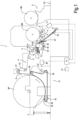
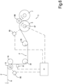
- a rewinder indicated as a whole with number 1, comprises a winding station 3, where a web material N, unwound from a primary reel BP, is wound on one or more secondary reels BS.
- P indicates the feeding path of the web material N, for example a non-woven fabric, from the primary reel BP towards the winding station 3.
- the feeding direction of the web material N is indicated with F.
- the secondary reels BS are formed around tubular winding cores arranged in the winding station 3.
- the overall structure of the rewinder 1 can be of a known type; therefore, only the main parts thereof, useful for understanding the present invention, will be described.
- the rewinder 1 is a so-called slitter-rewinder, or rewinder-slitter, which receives an intact web material and slits it into a plurality of longitudinal strips, each of which is wound onto a secondary reel BS.
- a secondary reel BS In the winding station 3, several secondary reels BS are arranged, adjacent to, and substantially coaxial with, one another, each receiving and winding a respective strip of web material.
- the winding station 3 comprises a winding cradle.
- the winding cradle comprises peripheral winding members. These peripheral winding members may comprise two winding rollers 5 and 7, forming together the winding cradle. Each winding roller rotates around an axis, controlled for example by an electric motor. To this end, two separate motors, or a single motor with a transmission system can be provided.
- Fig. 1 shows schematically a motor 8 for controlling the winding rollers 5, 7.
- the rotation axes of the winding rollers 5, 7 are parallel to each another and lie on a substantially horizontal plane, so that the secondary reels BS can rest on the winding rollers 5, 7 by gravity.
- Further winding members may be also provided, for example a third winding roller arranged over the reels BS and having a mobile axis to follow the growth of the secondary reels BS during the winding cycle.
- Number 9 indicates an unloading system for unloading the secondary reels BS from the winding station 3.
- the rewinder 1 also comprises a cutting device 11 including a series of disc-shaped knives or blades 13 co-acting with a series of corresponding counter-blades 15 or with a counter-roller.
- the cutting device 11 can be configured in a known manner. Examples of cutting devices are described for instance in EP1245354 and EP1245519 , WO96/28285 , WO96/28284 , US2008/0148914 .
- Each blade 13 and each counter-blade 15 can be adjustable in transverse direction, i.e. orthogonally to the feeding path P of the web material N, to cut longitudinal strips of web material of suitable width.
- Fig. 4 schematically shows six cutting blades 13, which slit the web material N into five longitudinal strips S1, S2, S3, S4, S5 and two lateral trimmings R1, R2. The number of longitudinal strips is purely indicative. In general, the web material N can be slit into a plurality of "n" strips S 1-Sn.
- the reference number 12 indicates a device for detecting the position in the transverse direction (i.e. orthogonally to the plane of the figure) of the blades 13.
- the device 12 may comprise an encoder, which detects the absolute displacements of the individual blades when they are positioned.
- Systems for detecting the blade position are known per se; therefore, they are not described in detail herein.
- the device 12 can be useful not only for knowing and storing the blade position, in order to manage it, but also for determining the width of the strips of web material in the area where they are formed, slit by the blades 13 and the counter-blades 15.
- guide rollers 17, 19, 21 can be arranged upstream of the cutting device 11, and guide rollers 23, 25 can be arranged downstream of the cutting device.
- the number and position of the guide rollers are given just by way of example.
- one of the rollers upstream of the cutting device 11, for example the roller 17, can be a bowed roller, i.e. a so-called banana roller, which transversely stretches the web material N to remove wrinkles or creases.
- the rewinder 1 may comprise an unwinder 31, provided with members for unwinding the primary reels BP.
- the unwinder 31 can be an integral part of the rewinder 1, or it can be a separate machine combined with the rewinder 1.
- the unwinder 31 comprises unwinding members, for example tailstocks, which axially engage the primary reel BP.
- the unwinder comprises peripheral unwinding members 33, which may comprise one or more continuous belts 35 driven around pulleys 37, 39, one of which (for example the pulley 37) is motorized.
- number 38 schematically indicates the motor of the motorized pulley.
- Guide rollers 41, 43 can be provided to guide the web material N towards the banana roller 17.
- central and peripheral unwinding members can be provided in combination.
- the rewinder 1 of Fig. 1 is provided with a web material evaluation system comprising a first video camera 51 and a second video camera 53.
- the video cameras 51, 53 can be housed in a pit under the floor PC, on which the main structure of the rewinder 1 stands, and can be arranged at such a distance from the feeding path P of the web material N as to frame the entire width of the web material N.
- the video cameras 51, 53 can be combined with lighting devices.
- a first lighting device 55 is provided for the first video camera 51 and a second lighting device 57 is provided for the second video camera 53.
- the first video camera 51 and the first lighting device 55 are arranged on opposite sides of the feeding path P.
- the first video camera 51 therefore captures transparent images of the web material N.
- the second video camera 53 and the second lighting device 57 are arranged on the same side of the feeding path P, and the second video camera 53 therefore acquires reflective images.
- Transparent or "in transparency” means that the web material N passes between the lighting device and the video camera, and it is therefore back-lit with respect to the video camera.
- contrast screen is arranged on the opposite side with respect to the video camera and the lighting device and is by the lighting device.
- the screen advantageously consists of a roller, around which the web material N is driven. In this case, focusing of the video camera is easier.
- a video camera is not able to frame the entire web material N in transverse direction, in order to analyze the entire width of the web material N several video cameras (usually two to four) can be provided, aligned with one other.
- the video cameras 51 and 53 with the respective lighting devices 55, 57 are arranged in the last segment of the feeding path P of the web material N, that is directly upstream of the first winding roller 5.
- no other mechanical members are arranged between the areas framed by the video cameras and the point where the strips of web material are wound onto the secondary reels BS. In this way, it is possible to capture images of the web material N exactly as it is wound on the secondary reels BS, without other operations being performed on the web material N that could lead to defects or otherwise modify the features of the strips of web material.
- the video cameras can be arranged further upstream than what illustrated in Fig. 1 , but preferably downstream of the cutting device 11.
- reference number 50 indicates a metal detector, which can be positioned downstream of the cutting device or unit 11, for example between the guide rollers 23 and 25. In this position, it is possible to detect the presence of metal particles, which can for example detach from the blades and/or counter-blades.
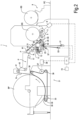
- Fig. 2 shows a second embodiment of a rewinder 1 according to the invention.
- the same numbers indicate equal or corresponding parts to those described with reference to Fig. 1 ; these parts will not be described again.
- two video cameras 51, 53 are provided with respective lighting devices 55 and 57, adapted to capture transparent and reflective images, similarly to what illustrated in Fig. 1 .
- the two video cameras 51, 53 are arranged slightly further upstream along the feeding path P and more exactly between the two guide rollers 23, 25 that are placed before the winding roller 5.
- This allows arranging a third video camera 61 with a respective lighting device 63 directly upstream of the first winding roller 5.
- the third video camera 61 captures reflective images.
- It can be arranged so as to frame a portion of web material N in contact with the winding roller 5 or, as shown in Fig. 5 , a portion of web material N in contact with a diffusing or reflecting screen 65, for example directly adjacent to the winding roller 5.
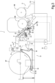
- FIG. 3 shows a rewinder 1, which differs from the previous ones mainly in the different arrangement of the video cameras.
- a first reflective video camera 53 is provided with a respective lighting device 55 that are arranged as in Fig. 1
- a second video camera 61 with a respective lighting device 63 that are arranged as in Fig. 2 , but without the video camera 51.
- only one video camera (or array of video cameras) can be provided, based on the reflection or, preferably, the transparency system.
- the video cameras can be interfaced with a programmable control and processing unit, for example a PLC or a computer, schematically indicated with 71.
- the programmable unit 71 collects and processes (in real or deferred time) the images captured by the video camera(s), with which the rewinder 1 is provided.
- the images can be processed, for example, for identifying any defects or criticalities in the web material N.
- the video cameras are arranged so as to frame the strips of web material N in areas very close to the winding point (winding rollers 5, 7), it is possible both to identify defects made on the web material in the last processing steps, for example when it is slit into strips, and exactly to localize in which secondary reel BS there is the detected defect.
- the purpose of the video camera system described herein is that of checking the web material at the end of the forming process and of web handling, in order to collect the defects due to both the processes (formation of the web material and handling thereof, for example cutting and rewinding thereof). Therefore, the system is not used to prepare a map of the defects allowing the operator to remove the defects from the web material during the rewinding phase, but to certify the quality of the secondary BS reels produced by the manufacturer of the non-woven fabric or other web material N.
- This novel arrangement of video cameras in the rewinder 1 has many advantages, some of which are listed below.
- the system can verify that the operator of the rewinding machine has effectively removed all the defects detected by the first vision system (and/or by the metal detector), installed upstream of the winder (not shown). In fact, it could happen that, by mistake, the product destined to be discarded is wound into secondary reels BS destined to the sale. For example, when starting the production of a certain type of non-woven fabric, for technological reasons a non-calendered non-woven fabric is produced, destined to be wasted and usually excluded from the rewinding process; but due to an operator error it could be wound into secondary reels destined to the sale.
- the novel arrangement of video cameras according to the invention prevents this.
- the video cameras arranged as described above allow verifying that no longitudinal creases are formed during cutting and rewinding.
- longitudinal creases may be formed. These are formed due to aerodynamic effects acting when the web material moves forward at high speed and disappear when the web material moves forward at low speed. That is, the creases are formed during normal winding, but disappear when the outer turns of the secondary reel are wound.
- the outer turns of the secondary reels BS are wound when the rewinder is in deceleration ramp step, i.e. when the speed of the web material is reduced. Due to this, a simple visual examination of the outside of the secondary reel BS does not allow to recognize whether the reel has longitudinal creases thereinside. On the contrary, the arrangement of video cameras described herein makes it possible to identify this defect, independently of the step when it occurs.
- the arrangement of the video cameras described above allows controlling the quality of the cut edges so as to monitor the wear of the disc-shaped blades 13 cutting the edges.
- the video cameras also allow verifying whether a blade 13 has stopped cutting, thus compromising the good quality of the whole series of secondary BS reels wound in a winding cycle. In fact, if one of the blades 13 stops cutting, a wrap up of the whole machine can easily occur, which compromises the winding of the whole series of reels.
- the video cameras also allow to check the presence of all the strips S 1-Sn and to verify that they move in the desired direction forming the respective secondary reels BS. If, due to any problem (breakage of the strip, or other problem), the path of a strip changes and the strip starts to be wound around another mechanical member, this would lead to malfunctions and breakages of members of the rewinder, with consequent downtimes and production loss. Therefore, the prompt notification of situations of this type by using video cameras as described above has significant advantages in terms of time-savings and reduction of maintenance costs and spare parts.
- Video cameras may constitute systems for measuring the width of the strips and of the so-called neck-in between the various strips S1-Sn, i.e. the mutual distance between edges of adjacent longitudinal strips due to the transverse contraction thereof following the tension of the web material.
- the neck-in is the distance between the edge of one strip and the edge of the adjacent one.
- Determining the neck-in can be useful for various reasons. In particular, although not exclusively, determining the neck-in of a given web material facilitates prediction of the neck-in of web materials produced with different recipes.
- defects are found in diapers or in other finished products produced by using the web material of the secondary reels BS.
- insects can be found, caught in the plies of diapers.
- With a vision system installed immediately before winding it is easier, in these cases, to attribute the responsibilities.
- the width of the strips of wound web material is a quality index of the secondary reels BS.
- further components - such as glue, rubber bands, fluff, etc. - are placed on the web material unwound in the converting machine producing the finished articles (diapers or other products).
- the vision system by calculating instant by instant the width of the strips of web material, can certify that the width of the web material wound inside each secondary reel BS is within the allowable limits. Depending on the allowance, if necessary it is possible to classify the secondary reels BS in different quality classes, for example first choice reels and second choice reels.
- a further index of the quality of the reels is the flatness of the side thereof.
- the measurement of the absolute position of the edges of the various strips S1-Sn forming the various secondary reels BS is an indirect index of the flatness of the sides of the secondary reels BS.
- the web material evaluation system by controlling the position of the edges of the strips of web material, allows keeping under control also this feature of the secondary reels BS.
- the secondary reels BS having a defect inside are sorted by the packaging machines so that they are not sold as first quality reels, but follow a different path in the logistics system. For example, they can be sold as second quality reels or they can be used for recycling the raw material.
- tracing the map of the primary reel BP is also affected by parameters that are difficult to evaluate, such as:
- the web material In order to cut longitudinally the web material N into longitudinal strips S1-Sn by means of the blades or knives 13 of the cutting device 11, the web material must be subjected to a longitudinal tension. Once the web material N has been slit into longitudinal strips, due to the transverse contraction caused by the longitudinal traction, the width of each strip is smaller than the distance between the cutting edges of the blades 13, which have formed said strip. That is, after cutting the strip shrinks, due to the tension and the high value of the Poisson's ratio of the web material.
- Fig. 4A this phenomenon is schematically shown.
- the distance between adjacent edges of two adjacent strips is called “neck-in” and is indicated, in Fig. 4A , with NI.
- the neck-in is shown between the longitudinal edge B2 of the strip S2 and the longitudinal edge B3 of the adjacent strip S3.
- the positioning in transverse direction of the blades 13 and of the respective counter-blades 15 is controlled by a computer or a programmable control unit 71 which calculates the different locations at which the blades shall be positioned based on the width of the longitudinal strips S 1-Sn of web material N to be produced.
- the calculation program for positioning the blades 13 requires the operator to input data, including the width of each strip to be obtained and the shrinkage value (the neck-in value).
- Each blade is positioned in the centerline of the neck-in (or in such an intermediate position that the fraction of neck-in which is to the left of the blade 13 is proportional to the width of the strip S 1-Sn to the left of said blade, while the fraction of neck-in which is to the right of the blade 13 is proportional to the width of the strip to the right of said blade.
- Other alternative proportionality criteria are also possible.
- the secondary reels BS are packaged and prepared for shipment to the converting plant, they are stacked with the rotation axis thereof in vertical position, so that during transport the reels do not take an oval shape.
- the tubular winding cores In order for the stack of reels to be stable, the tubular winding cores must not project axially from the reels.
- the secondary reels BS are unwound to produce the final product (for example diapers, sanitary napkins, soaked wipes, and other articles), they are positioned on the unwinding reel of the converting machine.
- the correct axial position is identified by placing the tubular winding core against an axial reference provided on the winding reel. Any protrusion of the tubular winding core from the flat end surfaces of the reel would lead to positioning errors, negatively affecting the production of the finished product.
- the strip width values can be evaluated easy, because they represent the goal of the production, the neck-in values are difficult to be determined.
- the width of the neck-in is affected by many factors, including: the mechanical properties of the web material; the width of the strips adjacent to the neck-in; the temperature of the web material during the rewinding step; the tension to which the web material is subject; the effect of the banana roller 17 or of any other system for spreading the web material.
- the data on the width of strips and neck-ins are used by the machines that shall cut and position the tubular winding cores of the secondary reels BS on winding rods or shafts, which are then inserted into the winding station 3 for forming, around each tubular winding core, a respective secondary reel BS.
- the tubular winding cores are formed by cutting a tube of greater axial length and positioned on the winding rods or shafts so that the edges of the winding cores are aligned with the flat faces of the reels.
- the neck-ins are evaluated based on work experience, or based on attempts by successive approximations. This method is not satisfactory.
- some embodiments of the rewinders disclosed herein allow to measure the position of the edges of the web material N slit into longitudinal strips S1-Sn in a suitable position, and preferably immediately before the winding point, so as to transmit the necessary data to the machines preparing the winding rod or shaft, with the tubular winding cores inserted thereon.
- the aim is to loop-close the chain of operations that includes:
- the web material evaluation system N described herein allows to detect accurately the position of each longitudinal edge (e.g. the edges B2, B3 in Fig. 4A ) and then to determine or verify the width of each strip and the neck-in NI (see Fig. 4A ) between each pair of adjacent strips. Based on these data, it is possible to prepare tubular winding cores of correct axial length and to position them accurately onto the respective winding rod or shaft. In this way, the edges of the tubular winding cores will coincide with the edges of the strips S1-Sn, without the need for the operator to intervene for processing and inputting data. Consequently, the ends of each tubular winding core will be surely in the correct position with respect to the flat surfaces of the respective secondary reel BS.
- the position of the longitudinal edges of the strips S1-Sn can be detected, downstream of the cutting device 11, by means of one or more video cameras, with which the machine 1 is provided.
- a pair of secondary reels BS1, BS2 are schematically shown, onto which two strips S1 and S2 respectively of web material N are being wound.
- B1 and B2 indicate the longitudinal edges adjacent to each other of the strips S1 and S2.
- the secondary reels BS1, BS2 are wound around tubular cores T, inserted and locked onto a winding rod or shaft A.
- the shaft can be expandable, for example pneumatically, in known manner.
- a variable number of tubular winding cores can be mounted onto the shaft, corresponding to the number of secondary reels being formed simultaneously.
- the tubular cores T have ends that are inside or preferably flush with the head surfaces, or flat front surfaces BSF1 and BSF2 of the secondary reels BS1, BS2. In this way, the tubular winding cores T do not constitute an obstacle to the subsequent processing and converting of the secondary reels BS.
- a vision system can be used, comprising at least one video camera or more video cameras aligned with one another, as described with reference to Figs. 1 , 2 , and 3 .
- the video camera(s) may be arranged to frame the web material N slit into strips immediately upstream of the winding point, as illustrated for example in Fig. 1 for the video camera 51 or in Figs. 2 and 3 for the video camera 61. In this way, the data on the width of the strips S 1-Sn and the size of the neck-in are accurately determined and cannot be modified due to further processing before winding.
- the following method can be performed.
- the web material N is drawn in the rewinder.
- the positions of the blades 13 and of the counter-blades 15 of the cutting device 11 are set according to the width of the various strips S1-Sn to be obtained, as well as the assumed neck-in values, for example estimated based on the operator's experience. All the machine parameters are set according to the desired production, for example: tension of the web material, stretching of the web material between the rollers along the feeding path P, position of the banana roller 17 (or of another spreading system for spreading the web material N).
- Tubular winding cores T are cut to a size corresponding to the width of the strips to be obtained, and are positioned on the winding shaft or rod A in the positions corresponding to the positions of the respective strips S 1-Sn, taking into account the estimated neck-in values and the winding shaft or rod with the tubular winding cores T is placed in the winding station 3.
- the rewinder 1 is started at reduced speed and so that it can process a small length of web material (small compared to the length wound on a reel).
- the web material evaluation system acquires data for determining the effective width of the strips S 1-Sn and the actual size of the neck-in.
- the rewinder 1 stops and the material that has just passed through the rewinder is discarded.
- the blades 13 and the counter-blades 15 of the cutting device 11 are positioned again, defining their position by means of a mathematical calculation based on the acquired data on the effective width of the strips and the neck in.
- the mathematical calculation can be based for example on the following approach.
- the neck-ins do not vary between the production made with the blades 13 and counter-blades 15 in the first position and in the second position, while the width of the strips S1-Sn is changed by the mathematical calculation. That is, the distance between two cutting edges of blades 13 is adjusted according to the error on the neck-in and according to the error recorded on the width of the strips.
- the neck-in values follow a proportionality principle with respect to the width of the adjacent strips.
- the position of the cutting edges of the disc-shaped blades 13 is not in the center of the neck-in; contrarily, the neck-in is subdivided by the cutting edge into two portions, each proportional to the width of the adjacent strip.
- Proportionality may refer to direct proportionality, or to proportionality with respect to a function where the independent variables are the width of the strips on the right and on the left of the neck-in in question.
- the actual production of the batch of secondary reels BS starts after having removed the first series of secondary reels BS and after having repositioned the blades 13 and the counter-blades 15. Before starting the actual production, the following three interventions may be performed:
- the method can be also further improved for taking into account other factors that could affect the correct winding, and therefore the quality, of the secondary reels BS.
- the secondary reels BS produced by the rewinders 1 may be used, for example, for producing baby or adult diapers, sanitary napkins or other finished products particularly complex to be produced and for which some qualitative features of the secondary reels BS are critical.
- the qualitative needs may be, in particular, the flatness of the head surfaces (BSF1, BSF2, Fig.5 ) of the secondary reels BS, as well as the constant width of the reel.
- edges of the strip of web material coming from a secondary reel BS being unwound in the converting machine are not always in the same position, and move transversely with respect to the feeding direction, for example due to a nonuniform width of the strip wound into the secondary reel BS, or due to a zig-zag pattern of the edges, problems could arise in forming the finished products.
- the various layers of the product could be glued in a wrong position, the glue could exit the edges of the diaper or sanitary napkin, the cutting dies of the single diapers or napkins could leave traces on the precut material.
- the constant width of the strip of a primary reel BP being unwound and the constant position of the edges B2, B3 of a strip S1-Sn coming from the cutting device 11, are particularly important factors for evaluating the quality of the secondary reels BS produced, and for guaranteeing the absence of problems in the operation of the converting machine used for producing finished products starting from the secondary reels BS.
- the width of the strips and the position of the edges of each strip S1-Sn being wound are controlled indirectly.
- the mechanical properties (elastic modules, Poisson's ratio, etc.) of the web material N remain constant throughout the length of the web material N, and particular attention is given to keep the tension of the web material N under control along the feeding path P, to avoid a variable contraction of the strips S1-Sn during winding.
- the tension of the web material is detected through rollers mounted with the interposition of load cells, whose signal is used as feedback signal to manage the motor 38 of the unwinder 31.
- the motor of the unwinder 31 transmits the motion to the primary reel BP by means of a mechanical transmission and belts 35, which connect the mechanical members, driven in rotation by the motor, with the outer surface of the primary reel BP.
- a direct proportionality (at least at theoretical level) between the angular speed of the drive shaft actuating the belts 35 of the unwinding members 33 and the peripheral speed of the belts 35 and therefore of the cylindrical outer surface of the primary reel BP.
- the motor 38 of the unwinder 31 is controlled so that the peripheral speed of the unwinding belts 35 is the same as the peripheral speed of the rollers 5, 7 of the winding station 3, on which the secondary reels BS are formed.
- the motor 38 interfaces the control unit and the signal driving the motor 38 of the unwinder 31 is operated by the signal coming from the load cells via a PID (proportional, integral, derivative) regulator.
- the other rollers of the rewinding machine are controlled with a speed variation (in percentage) with respect to the speed of the winding rollers 5, 7 or to the speed of the motor 38 of the unwinder 31. The percentage values of speed variation of the various rollers are set by the operator.
- the rewinder is a start-stop machine, that is, it starts from a complete standstill, accelerates up to the working speed set by the operator, keeps this speed for a certain period of time or for a certain winding length, and then decelerates until stopping to allow the removal of the secondary reels BS formed. It is therefore a machine, whose rollers are subject to accelerating and decelerating torques.
- width of the strips which negatively affect the quality of the secondary reels BS produced, can result from the reciprocal sliding or shifting between the web material N and one or more of the rollers determining the traction thereof. Shifting can occur in particular in the acceleration and deceleration transients of the rewinding machine.
- the winding tension of the web material results from the behavior of each motor involved in the actuation of one or more web material feeding members.
- the feedback on the motors can be done directly in the drive of the respective motor or by a PLC controlling the various drives of the motors.
- one or more of the following data can be used as a signal to manage the various motors driving the feeding members:
- control of one or more of the motors actuating the web material feeding members can be such as to keep one or more parameters or features of the strips, and therefore of the secondary reels BS, constant.
- one or more motors of the rewinder can be controlled by means of a feedback loop so as to correct any deviations from a set value of the neck-in and/or of the width of the strips, so as to keep these parameters perfectly constant, or within defined tolerance limits, for the entire winding cycle.
- the rewinding method described herein can use the information acquired by the evaluation system of the web material N to control one or more motors of the feeding members with the general purpose of controlling the position and/or the width of the strips produced, without necessarily keeping these parameters constant, but setting a specific trend thereof during the winding cycle.
- the control described above it is also possible to use the control described above to impose a variation in the width of the strips, or a variation in the winding tension, as a function of the quantity (length or weight, for example) of material wound in the secondary reels BS, or the winding time.
- the web material feeding speed can be reduced, if necessary, up to the complete stop of the rewinder.
- the web material evaluation system can comprise an arrangement for measuring the Poisson's ratio, i.e. the ratio of transverse strain.
- Fig. 6 shows a simplified diagram of some parts of the rewinder 1, with a possible arrangement of members of the evaluation system of the web material N useful for detecting the Poisson's ratio. In Fig. 6 , equal numbers indicate parts already described with reference to Figs. 1 to 3 .
- the evaluation system elements used for measuring the Poisson's ratio can comprise a first device 81 for acquiring information on a first width (i.e. the transverse dimension with respect to the feeding direction) of the web material in a first position of the feeding path P.
- a second device 83 may be also provided for acquiring information on a second width of the web material in a second position of the feeding path P.
- the devices 81 and 83 may be video cameras or linear video camera arrays, or any other device, for example of the type described above, adapted to detect the width of the web material N.
- the devices 81, 83 may also comprise one or more video cameras described above with reference to the diagrams of Figs. 1 to 3 , for example the video cameras 51, 53, 61.
- the first position where the first device 81 is arranged is immediately downstream of the cutting device 11 or in correspondence thereof. In this way it is possible to detect the width of each individual strip S1-Sn obtained by longitudinally cutting the web material N, or the width of only one or some strips.
- the second device 83 is arranged downstream of the first device and, in the example of Fig. 6 , in front of the winding roller 5.
- the two positions mentioned above of the devices 81 and 83 are given just by way of example, and different positions can be provided.
- the two positions are such that the feeding speed of the web material is slightly different in the two positions, so that the web material is subjected to longitudinal elongation due to the tension induced by the different feeding speeds, and consequently to transverse contraction.
- the two positions where the width of the web material is measured are arranged downstream (or in correspondence) of the cutting device 11, in other embodiments, not shown, the width and the feeding speed are detected upstream of the cutting device 11, so as to calculate the Poisson's ratio of the web material N before it is slit into strips S1-Sn.
- the device 81 may be associated with the unwinding members 33 of the unwinder 31.
- the first width of the strips can be measured by detecting the position of the cutting edges of the disc-shaped cutting blades 13.
- the first measurement position coincides with the position of the disc-shaped cutting blades 13 along the web material feeding path and the first measurement device can be a device detecting the transverse position (i.e. the position in direction orthogonal to the web material feeding direction) of the disc-shaped cutting blades 13.
- More than one pair of devices may be also provided for detecting the width of the web material, for example both upstream and downstream of the cutting device.
- a first measurement device 85 is also provided for measuring a first feeding speed of the web material N in the first position of the feeding path, and a second measurement device 87 for measuring a second feeding speed of the web material N in the second position of the feeding path.
- the speed measurement devices 85, 87 may comprise, for example, laser systems (known on the market), or devices for measuring the rotation speed of rotating members that are in contact with the web material N and whose peripheral speed is equal to the peripheral speed of the web material.
- inductive sensors lasers detecting one or more reflecting surfaces adequately arranged along the roller circumference
- magnetic sensors detecting one or more magnets adequately arranged along the roller circumference may be for example provided.
- the devices schematically indicated with 81 and 83 may be one or more of the devices mentioned above for determining the position of the edges of the web material N or of the strips S1-Sn, into which it has been slit.
- the first position where the devices 81 and 85 are arranged can match the point where the disc-shaped blades 13 and the counter-blades 15 perform the longitudinal cut.
- the width of the strips is equal to the distances between the cutting edges of the blades cutting the strips.
- the device 81 can simply be a device detecting the position of the cutting edges of the blades 13. No further detection means are therefore necessary to know the width of the strips in the first position.
- the longitudinal speed can be detected by optical means.
- the counter-blades are formed by a counter-roller wound by the web material N, if there is no relative sliding between the web material N and the counter-roller, the speed of the web material N can be equal to the peripheral speed of the counter-roller.
- the counter-roller rotation speed can be easily detected.
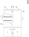
- Fig. 7 schematically shows two portions of web material N in the first and in the second position of the feeding path. More particularly, the web material in the first position is represented by a continuous line, while the web material in the second position is represented by a dotted line. Because of the traction applied to the web material, for example due to the different feeding speed in the two positions, the web material is elongated longitudinally and shrinks transversely, as schematically indicated in Fig. 7 .
- the values ⁇ L1 and ⁇ L2 are the length and width variations due to the traction, to which the web material is subjected in the portion between the two positions.
- a slitter-rewinder comprising a winding station, to which a series of strips of web material are fed, obtained by longitudinal cutting a web material from a primary reel unwound in an unwinding machine.
- Fig.8 shows a diagram of a winding machine 100 of this type.
- the winder 100 comprises a winding station 101, for example adapted to receive secondary winding cores that are adjacent to, and coaxial with, one another. In this embodiment again, as in the previous case, the winding cores can be inserted onto an expandable winding rod or shaft.
- the winding machine 100 also comprises a cutting device 104 with a plurality of blades 105 and one or more counter-blades 107.
- the cutting device 104 is arranged upstream of the winding station with respect to the feeding direction of the web material N along a feeding path P, and is configured to slit the web material N into a plurality of strips S1-Sn.
- the winding station 101 can comprise a winding roller 103, around which the strips of web material coming from the cutting device 104 are driven.
- Guide rollers 109, 111, 113, 114, and 115 may be arranged along the feeding path P of the web material N, both upstream and downstream of the cutting device 104.
- the winding machine 100 comprises a web material evaluation system.
- the evaluation system can comprise, for example, a metal detector 125, which has the same function as the metal detector 50 described with reference to Fig. 1 .
- the metal detector can be provided along the portion of feeding path P between the guide rollers 114 and 115, advantageously downstream of the cutting device 104.
- the web material evaluation system can comprise one or more video cameras, as described with reference to Figs. 1 to 3 .
- Fig.8 two video cameras 121 and 122 are shown, so arranged as to frame the web material feeding path downstream of the cutting device 104 and advantageously as close as possible to the winding roller 103, for the same purposes and reasons described above.
- Respective lighting devices schematically indicated with 123 and 124, are associated to the two video cameras 121, 122.
- the optical system comprising the video camera 121 and the lighting device 123 works in transparency, while the optical system comprising the video camera 122 and the lighting device 124 works in reflection.
- the number and arrangement of the video cameras are given just by way of example. In further embodiments, a greater number of video cameras or different positions thereof can be provided.
- each video camera 121, 122 can be one of a group, or linear matrix, of video cameras, aligned transversely to the feeding path P.
- the video cameras can be used to perform the functions described with reference to the previous embodiments, and in particular also for determining the Poisson's ratio, managing the neck-in of the web material and performing other functions described above.
- the winding machine can also comprise devices for detecting the feeding speed of the web material and the position of the cutting blades, for example for calculating the Poisson's ratio.
Landscapes
- Life Sciences & Earth Sciences (AREA)
- Forests & Forestry (AREA)
- Engineering & Computer Science (AREA)
- Mechanical Engineering (AREA)
- Controlling Rewinding, Feeding, Winding, Or Abnormalities Of Webs (AREA)
- Controlling Sheets Or Webs (AREA)
- Registering, Tensioning, Guiding Webs, And Rollers Therefor (AREA)
- Replacement Of Web Rolls (AREA)
- Treatment Of Fiber Materials (AREA)
Claims (17)
- Maschine (1; 100) zum Wickeln eines Bahnmaterials (N) in eine Anzahl von sekundären Rollen (BS) mit:einer Wickelstation (3; 101), die ausgebildet ist, um sekundäre Wickelkerne (T) koaxial mit und angrenzend aneinander aufzunehmen,einer Schneidvorrichtungen (11; 104) mit einer Anzahl von Klingen (13; 105), die stromauf der Wickelstation (3; 101) mit Bezug auf die Förderrichtung des Bahnmaterials (N) angeordnet ist und ausgebildet ist, um das Bahnmaterial in eine Anzahl von Streifen (S1-S5) von Bahnmaterial zu unterteilen,einem Bahnmaterial-Bewertungssystem,einer programmierbaren Einheit (71) zur Verarbeitung von Daten, die durch das Bahnmaterial-Bewertungssystem gesammelt wurden,wobei das Bahnmaterial-Bewertungssystem ausgebildet ist, um mindestens eines des folgenden zu erfassen: die Position von mindestens einer Längskante des Bahnmaterials, die Breite von mindestens einem Streifen des Bahnmaterials, dadurch gekennzeichnet, dassdie programmierbare Einheit (71) ausgebildet ist, um mindestens einen Parameter von mindestens einem Förderelement des Bahnmaterials (N) als eine Funktion der Erfassung des Bahnmaterial-Bewertungssystems zu modulieren.
- Maschine nach Anspruch 1, wobei die programmierbare Einheit (71) ausgebildet ist, um den mindestens einen Parameter zu modulieren, um die Spannung des Bahnmaterials zu modulieren oder ein Verschieben des Bahnmaterials in einer Querrichtung zu verhindern.
- Maschine nach Anspruch 1 oder 2, wobei der Parameter die Geschwindigkeit des mindestens einen Förderelements ist.
- Maschine nach einem oder mehreren der vorstehenden Ansprüche, wobei das Bahnmaterial-Bewertungssystem ein System (51, 53; 61; 121, 122) zum Aufnehmen von Bildern des Bahnmaterials (N) aufweist.
- Maschine nach Anspruch 4, wobei das Bildaufnahme-System mindestens eine der folgenden Kombinationen aufweist:eine einzelne Kamera (51, 53; 61; 121; 122), die ausgebildet ist, um eine erste Seite des Bahnmaterials (N) aufzunehmen,eine erste Kamera (51, 53; 61; 121; 122), die ausgebildet ist, um eine erste Seite des Bahnmaterials (N) aufzunehmen, und eine zweite Kamera (51; 53; 61; 121; 122), die ausgebildet ist, um eine zweite Seite des Bahnmaterials (N) aufzunehmen,eine Anzahl von Kameras (51; 53; 61; 121; 122), die ausgebildet ist um eine erste Seite des Bahnmaterials aufzunehmen, und eine weitere Kamera (51; 53; 61; 121; 122) oder eine Anzahl von weiteren Kameras (51; 53; 61; 121; 122), die ausgebildet sind, um eine zweite Seite des Bahnmaterials (N) aufzunehmen.
- Maschine nach Anspruch 5, wobei jeder Kamera (51, 53, 61; 121, 122) eine Beleuchtungsvorrichtung (55, 57, 63, 123, 124) zugeordnet ist, um einen Teil des Bahnmaterials (N), der durch die Kamera aufgenommen wird, zu beleuchten, und wobei mindestens eine Kamera und die entsprechende Beleuchtungsvorrichtung an gegenüberliegenden Seiten eines Förderwegs (P) des Bahnmaterials (N) angeordnet sind, sodass die Kamera übertragene Bilder des Bahnmaterials aufnimmt, und/oder wobei mindestens eine Kamera und die entsprechende Beleuchtungsvorrichtung auf derselben Seite des Bahnmaterial-Förderwegs angeordnet sind, sodass die Kamera reflektierte Bilder des Bahnmaterials aufnimmt.
- Maschine nach einem oder mehreren der vorstehenden Ansprüche, wobei das Bahnmaterial-Bewertungssystem in einem Bereich des Bahnmaterial-Förderwegs angeordnet ist der zwischen der Schneidvorrichtung (11; 104) und der Wickelstation (3; 101) vorhanden ist, und vorzugsweise zwischen einer Wickelrolle (5; 103) der Wickelstation (3; 101) und einer Führungswalze (25; 115), die direkt stromauf der Wickelrolle angeordnet ist.
- Maschine nach einem oder mehreren der vorstehenden Ansprüche, wobei das Bahnmaterial-Bewertungssystem Detektorelemente (50; 125) zur Erfassung der Anwesenheit von Metallresten in dem Bahnmaterial (N) aufweist.
- Verfahren zum Wickeln eines Bahnmaterials mit den folgenden SchrittenFördern eines Bahnmaterials (N) entlang eines Förderwegs (P) zu einer Wickelstation (3; 101), an der eine Reihe von Wickelkernen (T), die koaxial zueinander und angrenzend aneinander angeordnet sind, eingebracht werden,Schneiden des Bahnmaterials (N) in eine Anzahl von Streifen (S1-S5) von Bahnmaterial entlang des Förderwegs,Wickeln der Streifen des Bahnmaterials und dadurch Bildung von einer Anzahl von sekundären Rollen (BS),Erfassung von mindestens einem der folgenden Merkmale des Bahnmaterials entlang des Förderwegs: einer Position von mindestens einer Längskante des Bahnmaterials, einer Breite von mindestens einem Streifen des Bahnmaterials undModulieren mindestens eines Parameters von mindestens einem Bahnmaterial-Förderelement als eine Funktion des erfassten Merkmals.
- Verfahren nach Anspruch 9, wobei der mindestens eine Parameter eine Geschwindigkeit des mindestens einen Förderelements ist.
- Verfahren nach einem der Ansprüche 9 bis 10, wobei das Bahnmaterial von einer primären Rolle (BP) abgewickelt wird.
- Verfahren nach einem oder mehreren der Ansprüche 9 bis 11, wobei der Schritt der Erfassung von mindestens einem Merkmal des Bahnmaterials (N) den Schritt der Aufnahme von Bildern von mindestens einer Seite des Bahnmaterials (N) und vorzugsweise von beiden Seiten des Bahnmaterials aufweist.
- Verfahren nach einem oder mehreren der Ansprüche 9 bis 12, wobei das Merkmal des Bahnmaterials in einem Teil des Förderwegs stromab einer Schneidvorrichtungen (11; 101) erfasst wird, die das Bahnmaterial (N) in Streifen (S 1-S 5) des Bahnmaterials schneidet, und vorzugsweise direkt stromauf der Wickelstation (3; 101).
- Verfahren nach einem oder mehreren der Ansprüche 9 bis 13, wobei der Schritt der Modulation des mindestens einen Bahnmaterial-Förderelements den Schritt der Reduktion der Fördergeschwindigkeit des Bahnmaterials umfasst, wenn die Längskante des Bahnmaterials seitlich verschoben ist.
- Verfahren nach einem oder mehreren der Ansprüche 9 bis 14, wobei der Schritt der Modulation des mindestens einen Bahnmaterial-Förderelements den Schritt der Modulation einer Spannung des Bahnmaterials (N) entsprechend dem erfassten Merkmal umfasst.
- Verfahren nach Anspruch 15, wobei der Schritt der Modulation der Spannung den Schritt der Variation der Fördergeschwindigkeit des Bahnmaterials (N) an mindestens einem Punkt des Förderwegs umfasst, und insbesondere die Modulation der Differenz zwischen den Fördergeschwindigkeiten des Bahnmaterials an zwei Punkten des Förderwegs.
- Verfahren nach einem oder mehreren der Ansprüche 9 bis 16 mit den folgenden Schritten:Wickeln mindestens einer ersten Reihe von sekundären Rollen (BS), die jeweils durch einen Streifen (S1-S5) des Bahnmaterials (N) gebildet sind, auf jeweilige Wickelkerne (T) einer ersten Reihe von Wickelkernen, die in der Wickelstation (3; 101); 101) angeordnet sind, wobei die Streifen (S1-S5) von Bahnmaterial durch Schneiden mittels einer Anzahl von Klingen (13; 105) gebildet werden, die in einer ersten Schneidposition angeordnet sind,während des Wickelns der ersten Reihe von sekundären Rollen (B S), die Erfassung von Informationen der Position, die durch die Kanten der Streifen des Bahnmaterials eingenommen wird, und, basierend auf diesen Informationen, die Bestimmung der aktuellen Breite der Streifen (S1-S5) die auf die sekundären Rollen (BS) der ersten Reihe aufgewickelt werden, und dem gegenseitigen Abstand zwischen benachbarten Streifen,Entfernen der ersten Reihe von sekundären Rollen (BS) aus der Wickelstation (3),entsprechend der aktuellen Breite der Streifen (S1-SN) und dem gegenseitigen Abstand zwischen den Streifen, Neupositionierung der Klingen (13; 105) in einer zweiten Schneidposition, um so die Querkontraktion der Streifen (S1-S5) des Bahnmaterials (N) zu berücksichtigen, Positionieren einer zweiten Reihe von Wickelkernen (T) in der Wickelstation (3; 101), wobei die Kerne der zweiten Reihe entsprechend der aktuellen Breite der Streifen und dem gegenseitigen Abstand zwischen den Streifen (S1-S5) dimensioniert und positioniert werden,Wickeln einer zweiten Reihe von sekundären Rollen (BS) auf die zweite Reihe von Wickelkernen (T).
Applications Claiming Priority (2)
| Application Number | Priority Date | Filing Date | Title |
|---|---|---|---|
| IT201800009481 | 2018-10-16 | ||
| PCT/IB2019/058762 WO2020079576A1 (en) | 2018-10-16 | 2019-10-15 | Winding machine with an evaluation system of the web material being processed and method |
Publications (2)
| Publication Number | Publication Date |
|---|---|
| EP3867711A1 EP3867711A1 (de) | 2021-08-25 |
| EP3867711B1 true EP3867711B1 (de) | 2023-12-06 |
Family
ID=65031675
Family Applications (1)
| Application Number | Title | Priority Date | Filing Date |
|---|---|---|---|
| EP19798398.4A Active EP3867711B1 (de) | 2018-10-16 | 2019-10-15 | Wickelmaschine mit einem auswertesystem für das zu verarbeitende bahnmaterial und verfahren |
Country Status (11)
| Country | Link |
|---|---|
| US (1) | US12042949B2 (de) |
| EP (1) | EP3867711B1 (de) |
| JP (1) | JP7481018B2 (de) |
| CN (1) | CN113168150B (de) |
| BR (1) | BR112021007208A2 (de) |
| DK (1) | DK3867711T3 (de) |
| ES (1) | ES2973346T3 (de) |
| FI (1) | FI3867711T3 (de) |
| MX (1) | MX2021004341A (de) |
| PL (1) | PL3867711T3 (de) |
| WO (1) | WO2020079576A1 (de) |
Families Citing this family (4)
| Publication number | Priority date | Publication date | Assignee | Title |
|---|---|---|---|---|
| US20130063587A1 (en) * | 2011-03-09 | 2013-03-14 | Curt G. Joa, Inc. | Apparatus and method for minimizing waste and improving quality and production in web processing operations by automatic narrow web twist defect correction |
| CA3131574A1 (en) * | 2020-10-20 | 2022-04-20 | Valmet Technologies Oy | Slitter-winder |
| JP2024518745A (ja) * | 2021-04-21 | 2024-05-02 | ア.チエリ ノンヴオヴエンス ソチエタ ペル アチオーニ | ウェブ製品のリール形状を制御する装置 |
| WO2024157168A1 (en) * | 2023-01-26 | 2024-08-02 | A.Celli Paper S.P.A. | Winder with guide device for web product |
Family Cites Families (25)
| Publication number | Priority date | Publication date | Assignee | Title |
|---|---|---|---|---|
| US4342432A (en) * | 1981-01-30 | 1982-08-03 | Lund Arnold M | Control system for slitter-rewinder apparatus |
| JPH0631693A (ja) * | 1992-07-20 | 1994-02-08 | Toshin:Kk | 欠点検査装置を備えたスリッター |
| US5474248A (en) | 1993-08-16 | 1995-12-12 | Product Search, Inc. | Slitter/rewinder machine |
| BE1009187A5 (fr) | 1995-03-13 | 1996-12-03 | Celli A Belgium Sa | Systeme de coupe tangentielle automatique. |
| BE1009188A5 (fr) | 1995-03-13 | 1996-12-03 | Celli A Belgium Sa | Systeme de coupe tangentielle. |
| IT1308270B1 (it) | 1999-04-12 | 2001-12-10 | Celli Spa | Impianto e metodo per la preparazione di mandrini ed anime diavvolgimento per macchine ribobinatrici o simili |
| JP2002160118A (ja) * | 2000-11-22 | 2002-06-04 | Morimitsu:Kk | スリッターマシンにおけるスリッター装置 |
| DE60113502T2 (de) | 2001-03-26 | 2006-06-29 | A. Celli Nonwovens S.P.A., Porcari | Längsschneidvorrichtung zum Unterteilen einer Materialbahn und Umwickler mit solcher Vorrichtung |
| DE60108474T2 (de) * | 2001-03-26 | 2006-03-23 | A. Celli Nonwovens S.P.A., Porcari | Vorrichtung zur Verstellung von Schneidwerzeugen, Schneideanlage mit einer solchen Vorrichtung sowie Umspuler mit einer solchen Schneideanlage |
| JP2003276919A (ja) * | 2002-03-27 | 2003-10-02 | Nippon Paper Industries Co Ltd | 紙のスリッターエッジ検査装置と方法 |
| JP4553302B2 (ja) * | 2003-10-21 | 2010-09-29 | ヤヨイ化学工業株式会社 | 自動壁紙糊付機及び自動壁紙糊付機用スリッター |
| DE102004000034A1 (de) * | 2004-10-26 | 2006-04-27 | Voith Paper Patent Gmbh | Separiervorrichtung |
| ES2350045T3 (es) | 2004-11-25 | 2011-01-17 | Tomtec Imaging Systems Gmbh | Método y aparato para detectar movimientos de objetos. |
| BRPI0520056B1 (pt) | 2005-02-28 | 2019-04-30 | A. Celli Nonwovens S.P.A. | Dispositivo para corte longitudinal de um material em tela contínua e máquina possuindo o dito dispositivo |
| US7874593B1 (en) * | 2006-05-16 | 2011-01-25 | Stamps.Com Inc. | Rolls of image-customized value-bearing items and systems and methods for providing rolls of image-customized value-bearing items |
| CN101738396A (zh) * | 2008-11-18 | 2010-06-16 | 北京凌云光视数字图像技术有限公司 | 复检平台及印刷品质量检测系统 |
| FI122537B (fi) * | 2009-11-05 | 2012-03-15 | Metso Paper Inc | Menetelmä ja laitteisto rainamaisen materiaalin pituusleikkauksen ohjaamiseksi |
| HUE035089T2 (hu) * | 2012-02-24 | 2018-05-02 | Asd Therapeutics Partners Llc | Tiadiazolidindion-származékok mint GSK-3 inhibitorok |
| EP2703326B1 (de) * | 2012-08-29 | 2020-07-01 | Valmet Technologies, Inc. | Verfahren zum Abscheiden von Teilnetzen in einem Schneidewinder |
| GB2523390B (en) * | 2014-02-24 | 2017-11-29 | Essentra Packaging & Security Ltd | Method and apparatus for manufacturing a tape |
| CN105618839A (zh) * | 2016-02-29 | 2016-06-01 | 天津向荣铝业有限公司 | 一种切边机废边出料装置 |
| CN106018426A (zh) * | 2016-07-20 | 2016-10-12 | 武汉大学 | 印刷品质量在线检测系统 |
| CN207181313U (zh) * | 2017-09-15 | 2018-04-03 | 连云港三叶无纺布制品有限公司 | 一种全自动污点检测分切复卷机 |
| CN107462582A (zh) * | 2017-09-15 | 2017-12-12 | 连云港三叶无纺布制品有限公司 | 全自动污点检测分切复卷机 |
| JP7044583B2 (ja) * | 2018-02-22 | 2022-03-30 | 住友化学株式会社 | フィルムの製造方法、フィルム捲回装置 |
-
2019
- 2019-10-15 DK DK19798398.4T patent/DK3867711T3/da active
- 2019-10-15 US US17/285,613 patent/US12042949B2/en active Active
- 2019-10-15 ES ES19798398T patent/ES2973346T3/es active Active
- 2019-10-15 PL PL19798398.4T patent/PL3867711T3/pl unknown
- 2019-10-15 EP EP19798398.4A patent/EP3867711B1/de active Active
- 2019-10-15 JP JP2021521021A patent/JP7481018B2/ja active Active
- 2019-10-15 BR BR112021007208-0A patent/BR112021007208A2/pt unknown
- 2019-10-15 WO PCT/IB2019/058762 patent/WO2020079576A1/en unknown
- 2019-10-15 FI FIEP19798398.4T patent/FI3867711T3/fi active
- 2019-10-15 CN CN201980077696.9A patent/CN113168150B/zh active Active
- 2019-10-15 MX MX2021004341A patent/MX2021004341A/es unknown
Also Published As
| Publication number | Publication date |
|---|---|
| ES2973346T3 (es) | 2024-06-19 |
| DK3867711T3 (da) | 2024-03-11 |
| FI3867711T3 (fi) | 2024-03-13 |
| JP2022505112A (ja) | 2022-01-14 |
| EP3867711A1 (de) | 2021-08-25 |
| US20210394386A1 (en) | 2021-12-23 |
| BR112021007208A2 (pt) | 2021-08-10 |
| PL3867711T3 (pl) | 2024-05-20 |
| US12042949B2 (en) | 2024-07-23 |
| WO2020079576A1 (en) | 2020-04-23 |
| CN113168150A (zh) | 2021-07-23 |
| CN113168150B (zh) | 2024-05-10 |
| JP7481018B2 (ja) | 2024-05-10 |
| MX2021004341A (es) | 2021-08-19 |
Similar Documents
| Publication | Publication Date | Title |
|---|---|---|
| EP3867711B1 (de) | Wickelmaschine mit einem auswertesystem für das zu verarbeitende bahnmaterial und verfahren | |
| EP3867030B1 (de) | Wickelmaschine mit vorrichtung zur berechnung der poissonzahl und entsprechendes verfahren | |
| EP1568635B1 (de) | Verfahren und Apparat zum Wickeln von Film, Verfahren und Apparat zum Zuführen von Wickelkernen und Verfahren und Apparat zum Kontrollieren des Zustandes von Filmrollen | |
| US9138905B2 (en) | Method for calibrating the position of the slitter blades of a slitter-winder | |
| CN112236365B (zh) | 用于测试用于包装的可拉伸塑料薄膜的机器 | |
| EP2769813B1 (de) | Verfahren zur Kalibrierung der Position der Rollenschneidklingen eines Rollenschneiders | |
| US20200247634A1 (en) | Method and plant for producing logs of thin products | |
| US10343869B2 (en) | Machine for the production of spools with a system for alignment of the longitudinal cutting blades and the path of the longitudinal strips generated by cutting with the blades, and relevant method | |
| JP2001505860A (ja) | コイルまたはリール形成用連続平坦部材巻き上げ装置 | |
| JP6992340B2 (ja) | ウェブ弛み測定機構及びそれを備えたウェブ搬送装置 | |
| EP3718939B1 (de) | Vorrichtung und verfahren zur erkennung des vorhandenseins von abnormalitäten in einer rolle | |
| DK2497731T3 (en) | Apparatus and method for minimizing waste and improving quality and production machining operations of narrow lanes with automatic correction of snoningsfejl | |
| EP4086211A1 (de) | Fehlausrichtungsdetektor und fehlausrichtungsdetektionsverfahren in einer filmaufwickelmaschine | |
| US20240191985A1 (en) | Machine for controlling the shape of a reel of web product | |
| TWI857041B (zh) | 用以偵測捲盤中存在異常的裝置和方法 | |
| CN116902668A (zh) | 一种薄膜分切复卷检查机 |
Legal Events
| Date | Code | Title | Description |
|---|---|---|---|
| STAA | Information on the status of an ep patent application or granted ep patent |
Free format text: STATUS: UNKNOWN |
|
| STAA | Information on the status of an ep patent application or granted ep patent |
Free format text: STATUS: THE INTERNATIONAL PUBLICATION HAS BEEN MADE |
|
| PUAI | Public reference made under article 153(3) epc to a published international application that has entered the european phase |
Free format text: ORIGINAL CODE: 0009012 |
|
| STAA | Information on the status of an ep patent application or granted ep patent |
Free format text: STATUS: REQUEST FOR EXAMINATION WAS MADE |
|
| 17P | Request for examination filed |
Effective date: 20210414 |
|
| AK | Designated contracting states |
Kind code of ref document: A1 Designated state(s): AL AT BE BG CH CY CZ DE DK EE ES FI FR GB GR HR HU IE IS IT LI LT LU LV MC MK MT NL NO PL PT RO RS SE SI SK SM TR |
|
| DAV | Request for validation of the european patent (deleted) | ||
| DAX | Request for extension of the european patent (deleted) | ||
| GRAP | Despatch of communication of intention to grant a patent |
Free format text: ORIGINAL CODE: EPIDOSNIGR1 |
|
| STAA | Information on the status of an ep patent application or granted ep patent |
Free format text: STATUS: GRANT OF PATENT IS INTENDED |
|
| INTG | Intention to grant announced |
Effective date: 20230601 |
|
| GRAS | Grant fee paid |
Free format text: ORIGINAL CODE: EPIDOSNIGR3 |
|
| GRAA | (expected) grant |
Free format text: ORIGINAL CODE: 0009210 |
|
| STAA | Information on the status of an ep patent application or granted ep patent |
Free format text: STATUS: THE PATENT HAS BEEN GRANTED |
|
| AK | Designated contracting states |
Kind code of ref document: B1 Designated state(s): AL AT BE BG CH CY CZ DE DK EE ES FI FR GB GR HR HU IE IS IT LI LT LU LV MC MK MT NL NO PL PT RO RS SE SI SK SM TR |
|
| REG | Reference to a national code |
Ref country code: GB Ref legal event code: FG4D |
|
| REG | Reference to a national code |
Ref country code: CH Ref legal event code: EP |
|
| REG | Reference to a national code |
Ref country code: DE Ref legal event code: R096 Ref document number: 602019042899 Country of ref document: DE |
|
| REG | Reference to a national code |
Ref country code: IE Ref legal event code: FG4D |
|
| REG | Reference to a national code |
Ref country code: DK Ref legal event code: T3 Effective date: 20240305 |
|
| REG | Reference to a national code |
Ref country code: NL Ref legal event code: FP |
|
| REG | Reference to a national code |
Ref country code: SE Ref legal event code: TRGR |
|
| REG | Reference to a national code |
Ref country code: LT Ref legal event code: MG9D |
|
| P01 | Opt-out of the competence of the unified patent court (upc) registered |
Effective date: 20240221 |
|
| PG25 | Lapsed in a contracting state [announced via postgrant information from national office to epo] |
Ref country code: LT Free format text: LAPSE BECAUSE OF FAILURE TO SUBMIT A TRANSLATION OF THE DESCRIPTION OR TO PAY THE FEE WITHIN THE PRESCRIBED TIME-LIMIT Effective date: 20231206 |
|
| REG | Reference to a national code |
Ref country code: GR Ref legal event code: EP Ref document number: 20240400586 Country of ref document: GR Effective date: 20240410 |
|
| PG25 | Lapsed in a contracting state [announced via postgrant information from national office to epo] |
Ref country code: LT Free format text: LAPSE BECAUSE OF FAILURE TO SUBMIT A TRANSLATION OF THE DESCRIPTION OR TO PAY THE FEE WITHIN THE PRESCRIBED TIME-LIMIT Effective date: 20231206 Ref country code: BG Free format text: LAPSE BECAUSE OF FAILURE TO SUBMIT A TRANSLATION OF THE DESCRIPTION OR TO PAY THE FEE WITHIN THE PRESCRIBED TIME-LIMIT Effective date: 20240306 |
|
| PG25 | Lapsed in a contracting state [announced via postgrant information from national office to epo] |
Ref country code: RS Free format text: LAPSE BECAUSE OF FAILURE TO SUBMIT A TRANSLATION OF THE DESCRIPTION OR TO PAY THE FEE WITHIN THE PRESCRIBED TIME-LIMIT Effective date: 20231206 Ref country code: NO Free format text: LAPSE BECAUSE OF FAILURE TO SUBMIT A TRANSLATION OF THE DESCRIPTION OR TO PAY THE FEE WITHIN THE PRESCRIBED TIME-LIMIT Effective date: 20240306 Ref country code: LV Free format text: LAPSE BECAUSE OF FAILURE TO SUBMIT A TRANSLATION OF THE DESCRIPTION OR TO PAY THE FEE WITHIN THE PRESCRIBED TIME-LIMIT Effective date: 20231206 Ref country code: HR Free format text: LAPSE BECAUSE OF FAILURE TO SUBMIT A TRANSLATION OF THE DESCRIPTION OR TO PAY THE FEE WITHIN THE PRESCRIBED TIME-LIMIT Effective date: 20231206 |
|
| REG | Reference to a national code |
Ref country code: ES Ref legal event code: FG2A Ref document number: 2973346 Country of ref document: ES Kind code of ref document: T3 Effective date: 20240619 |
|
| PG25 | Lapsed in a contracting state [announced via postgrant information from national office to epo] |
Ref country code: IS Free format text: LAPSE BECAUSE OF FAILURE TO SUBMIT A TRANSLATION OF THE DESCRIPTION OR TO PAY THE FEE WITHIN THE PRESCRIBED TIME-LIMIT Effective date: 20240406 |
|
| PG25 | Lapsed in a contracting state [announced via postgrant information from national office to epo] |
Ref country code: SK Free format text: LAPSE BECAUSE OF FAILURE TO SUBMIT A TRANSLATION OF THE DESCRIPTION OR TO PAY THE FEE WITHIN THE PRESCRIBED TIME-LIMIT Effective date: 20231206 |
|
| PG25 | Lapsed in a contracting state [announced via postgrant information from national office to epo] |
Ref country code: SM Free format text: LAPSE BECAUSE OF FAILURE TO SUBMIT A TRANSLATION OF THE DESCRIPTION OR TO PAY THE FEE WITHIN THE PRESCRIBED TIME-LIMIT Effective date: 20231206 Ref country code: SK Free format text: LAPSE BECAUSE OF FAILURE TO SUBMIT A TRANSLATION OF THE DESCRIPTION OR TO PAY THE FEE WITHIN THE PRESCRIBED TIME-LIMIT Effective date: 20231206 Ref country code: RO Free format text: LAPSE BECAUSE OF FAILURE TO SUBMIT A TRANSLATION OF THE DESCRIPTION OR TO PAY THE FEE WITHIN THE PRESCRIBED TIME-LIMIT Effective date: 20231206 Ref country code: IS Free format text: LAPSE BECAUSE OF FAILURE TO SUBMIT A TRANSLATION OF THE DESCRIPTION OR TO PAY THE FEE WITHIN THE PRESCRIBED TIME-LIMIT Effective date: 20240406 Ref country code: EE Free format text: LAPSE BECAUSE OF FAILURE TO SUBMIT A TRANSLATION OF THE DESCRIPTION OR TO PAY THE FEE WITHIN THE PRESCRIBED TIME-LIMIT Effective date: 20231206 |
|
| PG25 | Lapsed in a contracting state [announced via postgrant information from national office to epo] |
Ref country code: PT Free format text: LAPSE BECAUSE OF FAILURE TO SUBMIT A TRANSLATION OF THE DESCRIPTION OR TO PAY THE FEE WITHIN THE PRESCRIBED TIME-LIMIT Effective date: 20240408 |
|
| PG25 | Lapsed in a contracting state [announced via postgrant information from national office to epo] |
Ref country code: PT Free format text: LAPSE BECAUSE OF FAILURE TO SUBMIT A TRANSLATION OF THE DESCRIPTION OR TO PAY THE FEE WITHIN THE PRESCRIBED TIME-LIMIT Effective date: 20240408 |
|
| PLBE | No opposition filed within time limit |
Free format text: ORIGINAL CODE: 0009261 |
|
| STAA | Information on the status of an ep patent application or granted ep patent |
Free format text: STATUS: NO OPPOSITION FILED WITHIN TIME LIMIT |