EP3867202B1 - Kolbenanordnung zur formung von bändern aus geschmolzenem glas - Google Patents
Kolbenanordnung zur formung von bändern aus geschmolzenem glas Download PDFInfo
- Publication number
- EP3867202B1 EP3867202B1 EP19805385.2A EP19805385A EP3867202B1 EP 3867202 B1 EP3867202 B1 EP 3867202B1 EP 19805385 A EP19805385 A EP 19805385A EP 3867202 B1 EP3867202 B1 EP 3867202B1
- Authority
- EP
- European Patent Office
- Prior art keywords
- assembly according
- plunger
- extruder
- support arm
- motorised
- Prior art date
- Legal status (The legal status is an assumption and is not a legal conclusion. Google has not performed a legal analysis and makes no representation as to the accuracy of the status listed.)
- Active
Links
Images

Classifications
-
- C—CHEMISTRY; METALLURGY
- C03—GLASS; MINERAL OR SLAG WOOL
- C03B—MANUFACTURE, SHAPING, OR SUPPLEMENTARY PROCESSES
- C03B7/00—Distributors for the molten glass; Means for taking-off charges of molten glass; Producing the gob, e.g. controlling the gob shape, weight or delivery tact
- C03B7/08—Feeder spouts, e.g. gob feeders
- C03B7/086—Plunger mechanisms
-
- C—CHEMISTRY; METALLURGY
- C03—GLASS; MINERAL OR SLAG WOOL
- C03B—MANUFACTURE, SHAPING, OR SUPPLEMENTARY PROCESSES
- C03B7/00—Distributors for the molten glass; Means for taking-off charges of molten glass; Producing the gob, e.g. controlling the gob shape, weight or delivery tact
- C03B7/005—Controlling, regulating or measuring
-
- C—CHEMISTRY; METALLURGY
- C03—GLASS; MINERAL OR SLAG WOOL
- C03B—MANUFACTURE, SHAPING, OR SUPPLEMENTARY PROCESSES
- C03B7/00—Distributors for the molten glass; Means for taking-off charges of molten glass; Producing the gob, e.g. controlling the gob shape, weight or delivery tact
- C03B7/08—Feeder spouts, e.g. gob feeders
- C03B7/094—Means for heating, cooling or insulation
Definitions
- This invention concerns a plunger assembly for forming ribbons of molten glass.
- IS machines which comprise a plunger assembly for forming one or more ribbon of molten glass and a cutting assembly for transversely and mechanically cutting each of the ribbons and producing a succession of glass drops. The drops thus formed are then deposited and processed inside moulds for forming articles.
- the plunger assembly comprises a molten glass container with one or more bottom openings and, for each of the openings, a corresponding vertical extruder plunger for extruding the glass through its corresponding opening.
- a single extruder plunger is generally used when producing one drop per cycle, or two to four extruder plungers to produce multiple drops simultaneously.
- the extruder plungers are supported by an end portion of a common handling arm, one opposite end portion of which is coupled to a vertically sliding slide.
- the displacement of the slide and, therefore, of the arm and of the plungers is controlled by a motorized cam group adapted to displace the arm and, therefore, the extruder plungers with a predefined motion profile.
- a motorized cam group adapted to displace the arm and, therefore, the extruder plungers with a predefined motion profile.
- each extruder plunger is coupled to a free end of its own arm, the opposite end of which is connected to a corresponding linear actuator independent of the other linear actuators.
- the support arms are very long, cantilevered arms and, as such, subject to high bending torques. It follows that it is extremely difficult to accurately control the weight variation of the drops formed, which, for light articles, are in the order of more or less 0.5% of the weight of the article formed and, therefore, a few tenths of a gram.
- plunger assemblies are disclosed in CN 206219422 U and CN 203947019 U .
- the purpose of this invention is to provide a plunger assembly for forming ribbons of molten glass, which allows the above problems to be solved in a simple and economical way and, in particular, a plunger assembly, in which the plungers can be operated independently and according to predefined laws of motion.
- a plunger assembly for forming ribbons of molten glass is provided, as claimed in claim 1.
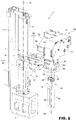
- the number 1 designates, as a whole, a forming assembly for ribbons of molten glass.
- the assembly 1 is configured to simultaneously form three ribbons 2 of molten glass that are equal or not and that are adapted to being transversely cut to produce a succession of drops 3 of glass by means of a cutting device 4, known and schematically shown.
- the assembly 1 comprises a bed 5, a pillar 6 extending upwards from the bed 5, and a guide-slide set 7 extending upwards from the bed 5 and coupled to the pillar 6.
- the guide-slide set 7 comprises a cylindrical guide 9 and a slide 10 that is coupled to the guide 9 in a sliding way in opposite directions and in an angularly fixed position.
- the position of the slide 10 along the guide 9 is adjustable by means of a motor 11 that drives a screw drive transmission 12. Once positioned, the slide is kept fixed for the whole process of forming the ribbons 2.
- the guide-slide set 12, the motor 11 and the transmission 12 can rotate around the axis 13 of the cylindrical guide 9 under the thrust of an actuator 14 between an operating or working position, shown in Figure 1 , and a rest position, which is adapted to enable the necessary maintenance operations.
- the slide 10 has an end portion of a horizontal support arm 15 integrally connected, an opposite end portion 16 of which is annular in shape and extends coaxially to a vertical axis 18.
- the end portion 16 of the arm 15 is coupled to a forming unit 19 that can be extracted or removed from above.
- the forming unit 19 comprises a cylindrical attachment and guide head 20, which extends coaxially to the axis 18 and comprises a lower cylindrical portion 21 that is inserted by means of a sliding coupling in the annular end portion 16, an intermediate outer flange 22 positioned above and against the annular portion 16, and an upper cylindrical portion 23.
- the head 20 is supported by the arm 15 and coupled to the arm 15 itself in a rotating manner inside the portion 16 around the axis 18.
- the head 20 is releasably locked to the portion 16 by means of a plurality of screws 24 that tighten the flange 22 against the same portion 16.
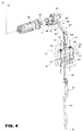
- the head 20 houses, locked in a fixed position, a multiple guide 25, shown in detail in Figure 4 .
- the multiple guide 25 has, in this case, three guide through holes 26 with respective axes 27 that are parallel to each other and to the axis 18 and aligned in one direction A.
- Each hole 26 is engaged in a sliding way by a corresponding through rod 28, which has a lower end portion firmly connected to an upper end portion of an extruder plunger 30, known in itself, and, conveniently, produced in ceramic material.
- Each rod 28 and its corresponding extruder plunger 30 are aligned with each other and coaxial to a common axis coinciding with the axis 27 of the respective guide hole 26.
- Each extruder plunger 30 is conveniently connected to its corresponding rod 28 via a quick coupling device 31. Irrespective of the connection mode, the extruder plungers 30 are arranged side-by-side in the A direction.
- the unit 19 also comprises an assembly 33 for handling the extruder plungers 30, carried by the arm 15 and configured to displace each extruder plunger 30 along the corresponding axis 27 of alternated cyclic motion and irrespective of the other extruder plungers 30.
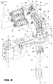
- the assembly 33 comprises a boxed support structure 34 carried by the arm 15 and extending above the arm 15 itself.
- the structure 34 comprises a lower attachment portion 35 that is firmly connected by means of screws to the upper cylindrical portion 23 of the head 20, and an upper support portion 36.
- Portion 36 protrudes upwards and laterally in a cantilever fashion from the lower portion 34 in a transverse direction to the arm 15.
- the boxed structure 34 conveniently comprises two plates 37 positioned so that they face each other and spaced apart in a direction orthogonal to the axes 18 and 27.
- the plates 37 are firmly connected to each other by means of a plurality of spokes 38, as shown in Figure 3 .
- the drive assembly 33 comprises, for each extruder plunger 30, a respective motorized displacement device 40, which is independent of the displacement devices 40 of the other extruder plungers 30.
- Each displacement device 40 comprises a corresponding mechanical lever transmission 41 driven by a corresponding gear motor 42.
- Each gear motor protrudes in a cantilever fashion beyond one of the plates 37 and has a corresponding output shaft 43 extending between the plates 37 orthogonally to the axes 18 and 27 and spaced apart from the other output shafts 43 at such a distance that the gear motors 42 are placed close to each other, as shown in Figure 3 .
- the gear motors 42 are controlled by a command and control unit 45 known in itself, which is configured to rotate the gear motors 42 of alternated cyclic motion and displace them according to laws of motion. These are known as electronic cams and are equal to each other or not, are stored in a memory block 46, and can be chosen according to the geometric characteristics and/or weight of the drops 3 to be produced.
- each mechanical transmission 41 comprises a kinematic connecting rod-crank 48 and a kinematic quadrilateral joint 49 positioned in cascade to each other, as clearly shown in Figure 4 .
- each kinematic connecting rod-crank 48 comprises a connecting rod 50 having a connecting rod foot coupled to a fixed hinge shaft 51 orthogonal to the axes 18 and 27 and parallel to the output shafts 43 and common to all kinematic connecting rod-cranks 48.
- the connecting rod foot is coupled to an intermediate section of the shaft 51 in a rotating manner and in an axially fixed position.
- Each crank 50 then has a connecting rod head hinged to a corresponding connecting rod 52 coupled, in turn, to the upper portion of its corresponding rod 28 by means of a crossed joint 53.
- each connecting rod foot has a crank 54 ( Figure 4 ) integrally connected and inclined with respect to a rod of the corresponding connecting rod 50 and forming part of the respective kinematic quadrilateral joint 49.
- each kinematic quadrilateral joint 49 comprises an additional crank 55 fitted to the output shaft 43 of the corresponding gear motor 42, and a corresponding connecting bar 56 for the crank heads 54 and 55.
- the boxed structure 34 then comprises a crankcase or boxed casing 57, which is coupled to the plates 37 in a removable way to define an inspectable housing chamber for the transmissions 41.
- the boxed structure 34 then comprises an additional crankcase or boxed casing 58, which extends to the side of the plate 37 facing the cylindrical guide 9 and delimits a gear motor housing chamber 42 communicating with the transmission chamber 41.
- the gear motor housing chamber 42 has an inlet opening 59 connected to a cooling air supply device 60 for the gear motors 42.
- the plunger assembly also comprises an additional air cooling device 61 for the head 20.
- the device 61 comprises a pipe 62 connected to a blower unit 63, on one side, and flowing into the arm 15 near the annular portion 16, on the other side.
- the cooling devices 60 and 61 are distinct and independent.
- the assembly 1 comprises, finally, a containment tank 65 of molten glass, known in itself and comprising a back wall equipped, for each extruder plunger 30, with a through outlet opening for the ribbon 2 of molten glass.
- the assembly 1 also comprises a rotating tube mechanism 65', also known in itself, which surrounds the extruder plungers 30.
- the slide 10 is brought to a predefined height, which is chosen according to the type of tank 63 and the height of the extruder plungers 30 used, via the motor 11, and is kept fixed in this position for the entire time the ribbons 2 are being formed.
- the command and control unit 45 controls the gear motors 42 in such a way as to translate each extruder plunger 30 along the corresponding axis 27 of alternated cyclic motion, and according to the law of motion stored in the memory block 46 of the unit 45, so that each extruder plunger 30 forms a corresponding ribbon 2 of molten glass, which is then cut by the cutting assembly 4 to form drops 3 of glass.
- each extruder plunger 30 is coupled to a corresponding rod 28 which is vertically guided by a fixed guide, so any transverse actions transferred to the same rod 28 are never transmitted to the corresponding extruder plunger 30.
- each gear motor 42 is independently controlled by the other gear motors 42, it is possible: to perform and control the law of motion of each extruder plunger 30 and, ultimately, the formed drop; and, via the feedback of a drop weight control system, for example, to perform the drop weight corrections in real time owing both to an overall drift of all the drops of a cutting cycle and to the drift of the single drop with respect to the others.
- each plunger axis control will intervene equally to correct the starting position of the cam and, if need be, its stroke. If only one drop has a weight that deviates from the nominal value, the axis control of the relevant extruder plunger will intervene, bringing the weight back within the set-up value, while the other extruder plungers will continue to operate with the set parameters.
- An additional advantage is the possibility of operating each single extruder plunger 30 with a cam other than the one used for the other extruder plungers. This solves some problems of drops with inconsistent shapes produced in the same cutting cycle. This last aspect is particularly useful in the case of multiple weight productions, where different sections of the machine have to produce articles of different weights. The possibility of easily controlling the shape and weight of the drop within the same cutting cycle, instils the system with greater flexibility and excellent compensation for any differences between the different drops produced.
- the assembly 1 described may be subject to modifications and variations without thereby departing from the protective scope defined in the independent claim.
- the assembly 1 may comprise a different number of extruder plungers than the one described, for example a single extruder plunger or a pair of extruder plungers.
- the extruder plungers could be controlled by transmissions other than those described but always positioned above the arm 15.
- the same transmissions could only comprise the kinematic connecting rod-crank.
- the transmissions may be driven by gear motors other than those indicated and, for example, by linear motors. Not only that, but the transmissions could be missing and the linear motors or linear actuators, in general, could be directly connected to the rods 28.
Landscapes
- Chemical & Material Sciences (AREA)
- Engineering & Computer Science (AREA)
- Materials Engineering (AREA)
- Organic Chemistry (AREA)
- Extrusion Moulding Of Plastics Or The Like (AREA)
- Moulding By Coating Moulds (AREA)
- Injection Moulding Of Plastics Or The Like (AREA)
Claims (15)
- Kolbenanordnung (1) zum Erzeugen von Tropfen (2) aus geschmolzenem Glas, wobei die Anordnung aufweist: einen feststehenden Rahmen (5); einen Behälter (65), der geeignet ist, eine Masse aus geschmolzenem Glas aufzunehmen; einen Tragarm (15), der sich ausgehend von dem feststehenden Rahmen oberhalb des Behälters (65) freitragend erstreckt; mindestens einen ersten Extruderkolben (30), der geeignet ist, zur Bildung eines Bandes (2) aus geschmolzenem Glas in den Behälter (65) eingeführt zu werden, und der seine eigene vertikale Achse (18) hat; eine erste motorisierte Handhabungseinrichtung (19) zum zyklischen Bewegen des Extruderkolbens (30) und zum Ausbilden des Bandes aus geschmolzenem Glas (2) und eine elektronische Steuereinheit (45) für die erste motorisierte Handhabungseinrichtung, die ausgebildet ist, um den ersten Extruderkolben mit einer alternierenden zyklischen Bewegung entlang der vertikalen Achse (18) und gemäß einem elektronischen Nocken von dem Behälter (65) weg und zu diesem hin zu bewegen, dadurch gekennzeichnet, dass der Tragarm (15) in Bezug auf den Rahmen (5) während der zyklischen Verschiebung des ersten Extruderkolbens (30) befestigt ist und die ersten motorisierte Einrichtung (19) den ersten Extruderkolben in Bezug auf den Tragarm (15) verschieben, und dass sie eine Befestigungsstruktur (34) für die ersten motorisiert Einrichtung, die von dem Tragarm (15) getragen werden, und einen Führungskopf (25) des ersten Extruderkolbens aufweist, der mit dem Tragarm (15) gekoppelt ist, um den ersten Extruderkolben (30) während der zyklischen Verschiebung in einer vertikalen Richtung parallel zu der vertikalen Achse (18) zu führen.
- Anordnung nach Anspruch 1, dadurch gekennzeichnet, dass sich die erste motorisierte Handhabungseinrichtung oberhalb des Tragarms (15) erstreckt.
- Anordnung nach Anspruch 1, dadurch gekennzeichnet, dass sich die erste motorisierte Handhabungseinrichtung zumindest teilweise an dem Tank (65) erstreckt.
- Anordnung nach einem der vorhergehenden Ansprüche, dadurch gekennzeichnet, dass die erste motorisierte Handhabungseinrichtung einen ersten Antriebsmotor (42) aufweist, der von der Befestigungsstruktur (43) getragen wird.
- Anordnung nach einem der Ansprüche 1 bis 4, dadurch gekennzeichnet, dass die Befestigungsstruktur (34) fest mit dem Führungskopf (25) verbunden ist.
- Anordnung nach Anspruch 5, dadurch gekennzeichnet, dass der Führungskopf (25) mit einem freien Endabschnitt des Tragarms (15) drehbar um eine vertikale Achse (18) und in einer vertikal fixierten Position gekoppelt ist; wobei Winkelverriegelungsmittel (22, 24) zum Verriegeln des Führungskopfes (25) auf dem Tragarm (15) in einer Mehrzahl von Winkelpositionen vorgesehen sind.
- Anordnung nach Anspruch 4, dadurch gekennzeichnet, dass der erste Antriebsmotor (42) ein Drehmotor oder ein Linearmotor ist.
- Anordnung nach Anspruch 4, dadurch gekennzeichnet, dass die ersten motorisierten Handhabungsmittel ferner ein erstes Getriebe (41) aufweisen, das zwischen dem ersten Motor (42) und dem ersten Extruderkolben (30) angeordnet ist; wobei das erste Getriebe (41) von der Befestigungsstruktur (34) getragen wird.
- Anordnung nach Anspruch 8, dadurch gekennzeichnet, dass das Getriebe (41) ein mechanisches Hebelgetriebe ist.
- Anordnung nach Anspruch 9, dadurch gekennzeichnet, dass das Getriebe (41) ein kinematisches Viereckgelenk (49) und eine kinematische Pleuelkurbel (48) aufweist.
- Anordnung nach Anspruch 4, dadurch gekennzeichnet, dass sie eine erste Luftkühlvorrichtung (60) für den Motor aufweist, wobei die erste Kühlvorrichtung zumindest teilweise von dem Tragarm (15) getragen wird.
- Anordnung nach Anspruch 11, dadurch gekennzeichnet, dass sie eine zweite Luftkühlvorrichtung (61) für den Führungskopf (25) aufweist.
- Anordnung nach Anspruch 12, dadurch gekennzeichnet, dass die erste (60) und die zweite Kühlvorrichtung (61) getrennt und unabhängig voneinander sind.
- Anordnung nach einem der vorhergehenden Ansprüche, dadurch gekennzeichnet, dass sie mindestens einen zweiten Extruderkolben (30) parallel zu dem ersten Extruderkolben und eine zweite motorisierte Handhabungseinrichtung aufweist, die von der Einheit (45) gesteuert wird, um den zweiten Extruderkolben mit einer alternierenden zyklischen Bewegung entlang seiner vertikalen Achse und in Bezug auf den Tragarm (15) zu verschieben; wobei die erste und die zweite motorisierte Handhabungseinrichtung unabhängig voneinander sind, um den zweiten Extruderkolben (30) unabhängig von dem ersten Extruderkolben (30) zu verschieben.
- Anordnung nach einem der vorhergehenden Ansprüche, dadurch gekennzeichnet, daß die Befestigungsstruktur, die motorisierte Handhabungseinrichtung und der Führungskopf einen Teil der Einheit ausbilden, der vertikal von dem Tragarm (15) abgekoppelt werden kann.
Applications Claiming Priority (2)
| Application Number | Priority Date | Filing Date | Title |
|---|---|---|---|
| IT102018000009629A IT201800009629A1 (it) | 2018-10-19 | 2018-10-19 | Gruppo punzone per la formatura di cordoni di vetro fuso |
| PCT/IB2019/058913 WO2020079663A1 (en) | 2018-10-19 | 2019-10-18 | Plunger assembly for forming ribbons of molten glass |
Publications (2)
| Publication Number | Publication Date |
|---|---|
| EP3867202A1 EP3867202A1 (de) | 2021-08-25 |
| EP3867202B1 true EP3867202B1 (de) | 2022-11-30 |
Family
ID=65199499
Family Applications (1)
| Application Number | Title | Priority Date | Filing Date |
|---|---|---|---|
| EP19805385.2A Active EP3867202B1 (de) | 2018-10-19 | 2019-10-18 | Kolbenanordnung zur formung von bändern aus geschmolzenem glas |
Country Status (5)
| Country | Link |
|---|---|
| US (1) | US11795092B2 (de) |
| EP (1) | EP3867202B1 (de) |
| CN (1) | CN113165931B (de) |
| IT (1) | IT201800009629A1 (de) |
| WO (1) | WO2020079663A1 (de) |
Family Cites Families (15)
| Publication number | Priority date | Publication date | Assignee | Title |
|---|---|---|---|---|
| CA334173A (en) * | 1933-07-18 | F. Rule John | Glass feeding apparatus | |
| GB316838A (en) * | 1928-12-05 | 1929-08-08 | William J Miller Inc | Improvements in or relating to machines for feeding mold charges of molten glass |
| GB619469A (en) * | 1946-12-12 | 1949-03-09 | Charles Van De Walle | Improvements in or relating to feeding apparatus for molten glass |
| US4551163A (en) * | 1984-06-04 | 1985-11-05 | Emhart Industries, Inc. | Electronic glass feeder plunger operating mechanism |
| IT1182522B (it) | 1985-07-17 | 1987-10-05 | Emhart Ind | Disposivivo a controllo elettronico per l azionamento di un alimentatore a stelo per vetro fuso |
| US5885317A (en) * | 1993-02-25 | 1999-03-23 | Owens-Brockway Glass Container Inc. | Multiple orifice glass feed system |
| US5660610A (en) * | 1994-10-24 | 1997-08-26 | Owens-Brockway Glass Container Inc. | Remotely adjustable glass feeder needle assembly |
| DE102004011647A1 (de) * | 2004-03-10 | 2005-09-29 | Heye International Gmbh | Verfahren und Vorrichtung zur Regelung der Glastropfenmasse bei der Herstellung von Hohlglasbehältern |
| JP5760334B2 (ja) | 2009-06-19 | 2015-08-05 | 大日本印刷株式会社 | 有機電子デバイス及びその製造方法 |
| EP2772956B1 (de) | 2011-10-25 | 2016-08-10 | Dai Nippon Printing Co., Ltd. | Material für eine positive lochinjektions-transportschicht, tinte für eine positive lochinjektions-transportschicht, vorrichtung und herstellungsverfahren dafür |
| CN103400941B (zh) | 2013-08-05 | 2015-10-28 | 苏州大学 | 基于杂多酸阳极修饰层的有机太阳能电池及其制备方法 |
| CN203947019U (zh) * | 2014-06-13 | 2014-11-19 | 山东三金玻璃机械有限公司 | 伺服冲料装置 |
| EP3313151A4 (de) | 2015-06-22 | 2019-02-20 | Sumitomo Chemical Company Limited | Verfahren zur herstellung eines organischen elektronischen elements und verfahren zur formung einer elektronenlochinjektionsschicht |
| KR101763468B1 (ko) | 2015-07-15 | 2017-08-02 | 건국대학교 산학협력단 | P-도핑된 공액 고분자 전해질을 이용한 유기 정공 수송 화합물, 이를 이용한 유기 전자 소자 및 이들의 제조방법 |
| CN206219422U (zh) * | 2016-11-09 | 2017-06-06 | 山东三金玻璃机械有限公司 | 一种供料机冲头高度调节装置 |
-
2018
- 2018-10-19 IT IT102018000009629A patent/IT201800009629A1/it unknown
-
2019
- 2019-10-18 EP EP19805385.2A patent/EP3867202B1/de active Active
- 2019-10-18 US US17/286,622 patent/US11795092B2/en active Active
- 2019-10-18 WO PCT/IB2019/058913 patent/WO2020079663A1/en not_active Ceased
- 2019-10-18 CN CN201980068561.6A patent/CN113165931B/zh active Active
Also Published As
| Publication number | Publication date |
|---|---|
| EP3867202A1 (de) | 2021-08-25 |
| CN113165931B (zh) | 2023-07-07 |
| CN113165931A (zh) | 2021-07-23 |
| IT201800009629A1 (it) | 2020-04-19 |
| US11795092B2 (en) | 2023-10-24 |
| WO2020079663A1 (en) | 2020-04-23 |
| US20210387888A1 (en) | 2021-12-16 |
Similar Documents
| Publication | Publication Date | Title |
|---|---|---|
| US4551163A (en) | Electronic glass feeder plunger operating mechanism | |
| US5267463A (en) | Automatic transfer apparatus for use in a forging press | |
| GB2229990A (en) | Gripping device for handling components | |
| EP2722314B1 (de) | Maschine zur herstellung von hohlem glas und dazu gehörendem verfahren | |
| EP4663611A1 (de) | Direktes einspeisen von glastropfen in quer verfahrbare rohlingsformen | |
| EP3867202B1 (de) | Kolbenanordnung zur formung von bändern aus geschmolzenem glas | |
| US20080152746A1 (en) | Machine For Moulding Plastic Containers Using Means For Moving The Mould-Support Unit Comprising Two In-Line Connecting Rods | |
| CN107902872B (zh) | 一种玻璃瓶供料机控制系统 | |
| EP0531899A1 (de) | Gerät und Verfahren zum Ausschieben | |
| EP0268414B1 (de) | Elektronische Servosteuerung der Glastropfen-Verteilung | |
| US5410974A (en) | Embroidery machine with center drive | |
| EP3092091B1 (de) | Maschine zum biegen eines bleches | |
| US5839340A (en) | Apparatus for cutting tubes | |
| CN101130449B (zh) | 用于使玻璃制品成形的装置和方法 | |
| KR100317274B1 (ko) | 다수의오리피스유리공급시스템 | |
| CN217879715U (zh) | 一种光纤拉锥装置 | |
| JP2017127894A (ja) | プレス装置 | |
| EP4206151B1 (de) | Handhabungseinheit zum bewegen eines formschliesselements einer maschine zur herstellung von glasartikeln | |
| US4463692A (en) | Shuttle embroidery machine | |
| CN109475952A (zh) | 用于制造包装的旋转刀和使用所述刀的方法 | |
| CA1236902A (en) | Electronic glass feeder plunger operating mechanism | |
| CN222552177U (zh) | 一种多光束金属3d打印喷头 | |
| JPH0985681A (ja) | シート状物品の切断装置とその製造方法 | |
| WO2019176883A1 (ja) | 平行リンク機構を備えた菓子製造システム | |
| US20020017077A1 (en) | Closing device for the closing tools of a bag-packing machine |
Legal Events
| Date | Code | Title | Description |
|---|---|---|---|
| STAA | Information on the status of an ep patent application or granted ep patent |
Free format text: STATUS: UNKNOWN |
|
| STAA | Information on the status of an ep patent application or granted ep patent |
Free format text: STATUS: THE INTERNATIONAL PUBLICATION HAS BEEN MADE |
|
| PUAI | Public reference made under article 153(3) epc to a published international application that has entered the european phase |
Free format text: ORIGINAL CODE: 0009012 |
|
| STAA | Information on the status of an ep patent application or granted ep patent |
Free format text: STATUS: REQUEST FOR EXAMINATION WAS MADE |
|
| 17P | Request for examination filed |
Effective date: 20210426 |
|
| AK | Designated contracting states |
Kind code of ref document: A1 Designated state(s): AL AT BE BG CH CY CZ DE DK EE ES FI FR GB GR HR HU IE IS IT LI LT LU LV MC MK MT NL NO PL PT RO RS SE SI SK SM TR |
|
| DAV | Request for validation of the european patent (deleted) | ||
| DAX | Request for extension of the european patent (deleted) | ||
| GRAP | Despatch of communication of intention to grant a patent |
Free format text: ORIGINAL CODE: EPIDOSNIGR1 |
|
| STAA | Information on the status of an ep patent application or granted ep patent |
Free format text: STATUS: GRANT OF PATENT IS INTENDED |
|
| INTG | Intention to grant announced |
Effective date: 20220524 |
|
| GRAS | Grant fee paid |
Free format text: ORIGINAL CODE: EPIDOSNIGR3 |
|
| GRAA | (expected) grant |
Free format text: ORIGINAL CODE: 0009210 |
|
| STAA | Information on the status of an ep patent application or granted ep patent |
Free format text: STATUS: THE PATENT HAS BEEN GRANTED |
|
| AK | Designated contracting states |
Kind code of ref document: B1 Designated state(s): AL AT BE BG CH CY CZ DE DK EE ES FI FR GB GR HR HU IE IS IT LI LT LU LV MC MK MT NL NO PL PT RO RS SE SI SK SM TR |
|
| REG | Reference to a national code |
Ref country code: CH Ref legal event code: EP Ref country code: GB Ref legal event code: FG4D |
|
| REG | Reference to a national code |
Ref country code: AT Ref legal event code: REF Ref document number: 1534577 Country of ref document: AT Kind code of ref document: T Effective date: 20221215 Ref country code: DE Ref legal event code: R096 Ref document number: 602019022652 Country of ref document: DE |
|
| REG | Reference to a national code |
Ref country code: IE Ref legal event code: FG4D |
|
| REG | Reference to a national code |
Ref country code: SE Ref legal event code: TRGR |
|
| REG | Reference to a national code |
Ref country code: LT Ref legal event code: MG9D |
|
| REG | Reference to a national code |
Ref country code: NL Ref legal event code: MP Effective date: 20221130 |
|
| PG25 | Lapsed in a contracting state [announced via postgrant information from national office to epo] |
Ref country code: PT Free format text: LAPSE BECAUSE OF FAILURE TO SUBMIT A TRANSLATION OF THE DESCRIPTION OR TO PAY THE FEE WITHIN THE PRESCRIBED TIME-LIMIT Effective date: 20230331 Ref country code: NO Free format text: LAPSE BECAUSE OF FAILURE TO SUBMIT A TRANSLATION OF THE DESCRIPTION OR TO PAY THE FEE WITHIN THE PRESCRIBED TIME-LIMIT Effective date: 20230228 Ref country code: LT Free format text: LAPSE BECAUSE OF FAILURE TO SUBMIT A TRANSLATION OF THE DESCRIPTION OR TO PAY THE FEE WITHIN THE PRESCRIBED TIME-LIMIT Effective date: 20221130 Ref country code: FI Free format text: LAPSE BECAUSE OF FAILURE TO SUBMIT A TRANSLATION OF THE DESCRIPTION OR TO PAY THE FEE WITHIN THE PRESCRIBED TIME-LIMIT Effective date: 20221130 Ref country code: ES Free format text: LAPSE BECAUSE OF FAILURE TO SUBMIT A TRANSLATION OF THE DESCRIPTION OR TO PAY THE FEE WITHIN THE PRESCRIBED TIME-LIMIT Effective date: 20221130 |
|
| REG | Reference to a national code |
Ref country code: AT Ref legal event code: MK05 Ref document number: 1534577 Country of ref document: AT Kind code of ref document: T Effective date: 20221130 |
|
| PG25 | Lapsed in a contracting state [announced via postgrant information from national office to epo] |
Ref country code: RS Free format text: LAPSE BECAUSE OF FAILURE TO SUBMIT A TRANSLATION OF THE DESCRIPTION OR TO PAY THE FEE WITHIN THE PRESCRIBED TIME-LIMIT Effective date: 20221130 Ref country code: PL Free format text: LAPSE BECAUSE OF FAILURE TO SUBMIT A TRANSLATION OF THE DESCRIPTION OR TO PAY THE FEE WITHIN THE PRESCRIBED TIME-LIMIT Effective date: 20221130 Ref country code: LV Free format text: LAPSE BECAUSE OF FAILURE TO SUBMIT A TRANSLATION OF THE DESCRIPTION OR TO PAY THE FEE WITHIN THE PRESCRIBED TIME-LIMIT Effective date: 20221130 Ref country code: IS Free format text: LAPSE BECAUSE OF FAILURE TO SUBMIT A TRANSLATION OF THE DESCRIPTION OR TO PAY THE FEE WITHIN THE PRESCRIBED TIME-LIMIT Effective date: 20230330 Ref country code: HR Free format text: LAPSE BECAUSE OF FAILURE TO SUBMIT A TRANSLATION OF THE DESCRIPTION OR TO PAY THE FEE WITHIN THE PRESCRIBED TIME-LIMIT Effective date: 20221130 Ref country code: GR Free format text: LAPSE BECAUSE OF FAILURE TO SUBMIT A TRANSLATION OF THE DESCRIPTION OR TO PAY THE FEE WITHIN THE PRESCRIBED TIME-LIMIT Effective date: 20230301 |
|
| PG25 | Lapsed in a contracting state [announced via postgrant information from national office to epo] |
Ref country code: NL Free format text: LAPSE BECAUSE OF FAILURE TO SUBMIT A TRANSLATION OF THE DESCRIPTION OR TO PAY THE FEE WITHIN THE PRESCRIBED TIME-LIMIT Effective date: 20221130 |
|
| PG25 | Lapsed in a contracting state [announced via postgrant information from national office to epo] |
Ref country code: SM Free format text: LAPSE BECAUSE OF FAILURE TO SUBMIT A TRANSLATION OF THE DESCRIPTION OR TO PAY THE FEE WITHIN THE PRESCRIBED TIME-LIMIT Effective date: 20221130 Ref country code: RO Free format text: LAPSE BECAUSE OF FAILURE TO SUBMIT A TRANSLATION OF THE DESCRIPTION OR TO PAY THE FEE WITHIN THE PRESCRIBED TIME-LIMIT Effective date: 20221130 Ref country code: EE Free format text: LAPSE BECAUSE OF FAILURE TO SUBMIT A TRANSLATION OF THE DESCRIPTION OR TO PAY THE FEE WITHIN THE PRESCRIBED TIME-LIMIT Effective date: 20221130 Ref country code: DK Free format text: LAPSE BECAUSE OF FAILURE TO SUBMIT A TRANSLATION OF THE DESCRIPTION OR TO PAY THE FEE WITHIN THE PRESCRIBED TIME-LIMIT Effective date: 20221130 Ref country code: AT Free format text: LAPSE BECAUSE OF FAILURE TO SUBMIT A TRANSLATION OF THE DESCRIPTION OR TO PAY THE FEE WITHIN THE PRESCRIBED TIME-LIMIT Effective date: 20221130 |
|
| PG25 | Lapsed in a contracting state [announced via postgrant information from national office to epo] |
Ref country code: SK Free format text: LAPSE BECAUSE OF FAILURE TO SUBMIT A TRANSLATION OF THE DESCRIPTION OR TO PAY THE FEE WITHIN THE PRESCRIBED TIME-LIMIT Effective date: 20221130 Ref country code: AL Free format text: LAPSE BECAUSE OF FAILURE TO SUBMIT A TRANSLATION OF THE DESCRIPTION OR TO PAY THE FEE WITHIN THE PRESCRIBED TIME-LIMIT Effective date: 20221130 |
|
| REG | Reference to a national code |
Ref country code: DE Ref legal event code: R097 Ref document number: 602019022652 Country of ref document: DE |
|
| PLBE | No opposition filed within time limit |
Free format text: ORIGINAL CODE: 0009261 |
|
| STAA | Information on the status of an ep patent application or granted ep patent |
Free format text: STATUS: NO OPPOSITION FILED WITHIN TIME LIMIT |
|
| 26N | No opposition filed |
Effective date: 20230831 |
|
| PG25 | Lapsed in a contracting state [announced via postgrant information from national office to epo] |
Ref country code: SI Free format text: LAPSE BECAUSE OF FAILURE TO SUBMIT A TRANSLATION OF THE DESCRIPTION OR TO PAY THE FEE WITHIN THE PRESCRIBED TIME-LIMIT Effective date: 20221130 |
|
| PG25 | Lapsed in a contracting state [announced via postgrant information from national office to epo] |
Ref country code: IT Free format text: LAPSE BECAUSE OF FAILURE TO SUBMIT A TRANSLATION OF THE DESCRIPTION OR TO PAY THE FEE WITHIN THE PRESCRIBED TIME-LIMIT Effective date: 20221130 Ref country code: MC Free format text: LAPSE BECAUSE OF FAILURE TO SUBMIT A TRANSLATION OF THE DESCRIPTION OR TO PAY THE FEE WITHIN THE PRESCRIBED TIME-LIMIT Effective date: 20221130 |
|
| REG | Reference to a national code |
Ref country code: BE Ref legal event code: MM Effective date: 20231031 |
|
| PG25 | Lapsed in a contracting state [announced via postgrant information from national office to epo] |
Ref country code: LU Free format text: LAPSE BECAUSE OF NON-PAYMENT OF DUE FEES Effective date: 20231018 |
|
| GBPC | Gb: european patent ceased through non-payment of renewal fee |
Effective date: 20231018 |
|
| PG25 | Lapsed in a contracting state [announced via postgrant information from national office to epo] |
Ref country code: LU Free format text: LAPSE BECAUSE OF NON-PAYMENT OF DUE FEES Effective date: 20231018 |
|
| PG25 | Lapsed in a contracting state [announced via postgrant information from national office to epo] |
Ref country code: GB Free format text: LAPSE BECAUSE OF NON-PAYMENT OF DUE FEES Effective date: 20231018 |
|
| PG25 | Lapsed in a contracting state [announced via postgrant information from national office to epo] |
Ref country code: GB Free format text: LAPSE BECAUSE OF NON-PAYMENT OF DUE FEES Effective date: 20231018 Ref country code: FR Free format text: LAPSE BECAUSE OF NON-PAYMENT OF DUE FEES Effective date: 20231031 |
|
| PG25 | Lapsed in a contracting state [announced via postgrant information from national office to epo] |
Ref country code: BE Free format text: LAPSE BECAUSE OF NON-PAYMENT OF DUE FEES Effective date: 20231031 |
|
| PG25 | Lapsed in a contracting state [announced via postgrant information from national office to epo] |
Ref country code: IE Free format text: LAPSE BECAUSE OF NON-PAYMENT OF DUE FEES Effective date: 20231018 |
|
| PG25 | Lapsed in a contracting state [announced via postgrant information from national office to epo] |
Ref country code: IE Free format text: LAPSE BECAUSE OF NON-PAYMENT OF DUE FEES Effective date: 20231018 |
|
| PG25 | Lapsed in a contracting state [announced via postgrant information from national office to epo] |
Ref country code: BG Free format text: LAPSE BECAUSE OF FAILURE TO SUBMIT A TRANSLATION OF THE DESCRIPTION OR TO PAY THE FEE WITHIN THE PRESCRIBED TIME-LIMIT Effective date: 20221130 |
|
| PG25 | Lapsed in a contracting state [announced via postgrant information from national office to epo] |
Ref country code: BG Free format text: LAPSE BECAUSE OF FAILURE TO SUBMIT A TRANSLATION OF THE DESCRIPTION OR TO PAY THE FEE WITHIN THE PRESCRIBED TIME-LIMIT Effective date: 20221130 |
|
| PG25 | Lapsed in a contracting state [announced via postgrant information from national office to epo] |
Ref country code: CY Free format text: LAPSE BECAUSE OF FAILURE TO SUBMIT A TRANSLATION OF THE DESCRIPTION OR TO PAY THE FEE WITHIN THE PRESCRIBED TIME-LIMIT; INVALID AB INITIO Effective date: 20191018 |
|
| PG25 | Lapsed in a contracting state [announced via postgrant information from national office to epo] |
Ref country code: HU Free format text: LAPSE BECAUSE OF FAILURE TO SUBMIT A TRANSLATION OF THE DESCRIPTION OR TO PAY THE FEE WITHIN THE PRESCRIBED TIME-LIMIT; INVALID AB INITIO Effective date: 20191018 |
|
| PGFP | Annual fee paid to national office [announced via postgrant information from national office to epo] |
Ref country code: SE Payment date: 20250923 Year of fee payment: 7 |
|
| PGFP | Annual fee paid to national office [announced via postgrant information from national office to epo] |
Ref country code: CZ Payment date: 20250929 Year of fee payment: 7 |
|
| REG | Reference to a national code |
Ref country code: CH Ref legal event code: U11 Free format text: ST27 STATUS EVENT CODE: U-0-0-U10-U11 (AS PROVIDED BY THE NATIONAL OFFICE) Effective date: 20251101 |
|
| PG25 | Lapsed in a contracting state [announced via postgrant information from national office to epo] |
Ref country code: TR Free format text: LAPSE BECAUSE OF FAILURE TO SUBMIT A TRANSLATION OF THE DESCRIPTION OR TO PAY THE FEE WITHIN THE PRESCRIBED TIME-LIMIT Effective date: 20221130 |
|
| PGFP | Annual fee paid to national office [announced via postgrant information from national office to epo] |
Ref country code: DE Payment date: 20250923 Year of fee payment: 7 |
|
| PGFP | Annual fee paid to national office [announced via postgrant information from national office to epo] |
Ref country code: CH Payment date: 20251101 Year of fee payment: 7 |