EP3867166B1 - Stackable container - Google Patents
Stackable container Download PDFInfo
- Publication number
- EP3867166B1 EP3867166B1 EP19794100.8A EP19794100A EP3867166B1 EP 3867166 B1 EP3867166 B1 EP 3867166B1 EP 19794100 A EP19794100 A EP 19794100A EP 3867166 B1 EP3867166 B1 EP 3867166B1
- Authority
- EP
- European Patent Office
- Prior art keywords
- container
- edge
- containers
- skirt
- latching
- Prior art date
- Legal status (The legal status is an assumption and is not a legal conclusion. Google has not performed a legal analysis and makes no representation as to the accuracy of the status listed.)
- Active
Links
- 238000007789 sealing Methods 0.000 claims description 19
- 238000010276 construction Methods 0.000 claims description 8
- 239000000463 material Substances 0.000 claims description 4
- 238000007373 indentation Methods 0.000 description 22
- 230000002093 peripheral effect Effects 0.000 description 10
- 238000002372 labelling Methods 0.000 description 6
- 230000008901 benefit Effects 0.000 description 3
- 230000015572 biosynthetic process Effects 0.000 description 3
- 230000000694 effects Effects 0.000 description 3
- 230000002349 favourable effect Effects 0.000 description 2
- 230000005484 gravity Effects 0.000 description 2
- 230000001771 impaired effect Effects 0.000 description 2
- 238000004519 manufacturing process Methods 0.000 description 2
- 230000003287 optical effect Effects 0.000 description 2
- 238000003860 storage Methods 0.000 description 2
- 230000009471 action Effects 0.000 description 1
- 230000008859 change Effects 0.000 description 1
- 238000004140 cleaning Methods 0.000 description 1
- 230000001419 dependent effect Effects 0.000 description 1
- 238000005265 energy consumption Methods 0.000 description 1
- 238000005429 filling process Methods 0.000 description 1
- 230000006872 improvement Effects 0.000 description 1
- 238000002347 injection Methods 0.000 description 1
- 239000007924 injection Substances 0.000 description 1
- 238000001746 injection moulding Methods 0.000 description 1
- 238000000034 method Methods 0.000 description 1
- 238000000465 moulding Methods 0.000 description 1
- 239000005022 packaging material Substances 0.000 description 1
- 238000004806 packaging method and process Methods 0.000 description 1
- 230000008569 process Effects 0.000 description 1
- 230000009467 reduction Effects 0.000 description 1
- 239000013585 weight reducing agent Substances 0.000 description 1
Images


Classifications
-
- B—PERFORMING OPERATIONS; TRANSPORTING
- B65—CONVEYING; PACKING; STORING; HANDLING THIN OR FILAMENTARY MATERIAL
- B65D—CONTAINERS FOR STORAGE OR TRANSPORT OF ARTICLES OR MATERIALS, e.g. BAGS, BARRELS, BOTTLES, BOXES, CANS, CARTONS, CRATES, DRUMS, JARS, TANKS, HOPPERS, FORWARDING CONTAINERS; ACCESSORIES, CLOSURES, OR FITTINGS THEREFOR; PACKAGING ELEMENTS; PACKAGES
- B65D21/00—Nestable, stackable or joinable containers; Containers of variable capacity
- B65D21/02—Containers specially shaped, or provided with fittings or attachments, to facilitate nesting, stacking, or joining together
- B65D21/0233—Nestable containers
-
- B—PERFORMING OPERATIONS; TRANSPORTING
- B65—CONVEYING; PACKING; STORING; HANDLING THIN OR FILAMENTARY MATERIAL
- B65D—CONTAINERS FOR STORAGE OR TRANSPORT OF ARTICLES OR MATERIALS, e.g. BAGS, BARRELS, BOTTLES, BOXES, CANS, CARTONS, CRATES, DRUMS, JARS, TANKS, HOPPERS, FORWARDING CONTAINERS; ACCESSORIES, CLOSURES, OR FITTINGS THEREFOR; PACKAGING ELEMENTS; PACKAGES
- B65D1/00—Containers having bodies formed in one piece, e.g. by casting metallic material, by moulding plastics, by blowing vitreous material, by throwing ceramic material, by moulding pulped fibrous material, by deep-drawing operations performed on sheet material
- B65D1/40—Details of walls
- B65D1/42—Reinforcing or strengthening parts or members
- B65D1/46—Local reinforcements, e.g. adjacent closures
-
- B—PERFORMING OPERATIONS; TRANSPORTING
- B65—CONVEYING; PACKING; STORING; HANDLING THIN OR FILAMENTARY MATERIAL
- B65D—CONTAINERS FOR STORAGE OR TRANSPORT OF ARTICLES OR MATERIALS, e.g. BAGS, BARRELS, BOTTLES, BOXES, CANS, CARTONS, CRATES, DRUMS, JARS, TANKS, HOPPERS, FORWARDING CONTAINERS; ACCESSORIES, CLOSURES, OR FITTINGS THEREFOR; PACKAGING ELEMENTS; PACKAGES
- B65D25/00—Details of other kinds or types of rigid or semi-rigid containers
- B65D25/28—Handles
- B65D25/32—Bail handles, i.e. pivoted rigid handles of generally semi-circular shape with pivot points on two opposed sides or wall parts of the conainter
-
- B—PERFORMING OPERATIONS; TRANSPORTING
- B65—CONVEYING; PACKING; STORING; HANDLING THIN OR FILAMENTARY MATERIAL
- B65D—CONTAINERS FOR STORAGE OR TRANSPORT OF ARTICLES OR MATERIALS, e.g. BAGS, BARRELS, BOTTLES, BOXES, CANS, CARTONS, CRATES, DRUMS, JARS, TANKS, HOPPERS, FORWARDING CONTAINERS; ACCESSORIES, CLOSURES, OR FITTINGS THEREFOR; PACKAGING ELEMENTS; PACKAGES
- B65D43/00—Lids or covers for rigid or semi-rigid containers
- B65D43/02—Removable lids or covers
- B65D43/0202—Removable lids or covers without integral tamper element
- B65D43/0204—Removable lids or covers without integral tamper element secured by snapping over beads or projections
- B65D43/0212—Removable lids or covers without integral tamper element secured by snapping over beads or projections only on the outside, or a part turned to the outside, of the mouth
-
- B—PERFORMING OPERATIONS; TRANSPORTING
- B65—CONVEYING; PACKING; STORING; HANDLING THIN OR FILAMENTARY MATERIAL
- B65D—CONTAINERS FOR STORAGE OR TRANSPORT OF ARTICLES OR MATERIALS, e.g. BAGS, BARRELS, BOTTLES, BOXES, CANS, CARTONS, CRATES, DRUMS, JARS, TANKS, HOPPERS, FORWARDING CONTAINERS; ACCESSORIES, CLOSURES, OR FITTINGS THEREFOR; PACKAGING ELEMENTS; PACKAGES
- B65D2303/00—Orienting or positioning means for containers
-
- B—PERFORMING OPERATIONS; TRANSPORTING
- B65—CONVEYING; PACKING; STORING; HANDLING THIN OR FILAMENTARY MATERIAL
- B65D—CONTAINERS FOR STORAGE OR TRANSPORT OF ARTICLES OR MATERIALS, e.g. BAGS, BARRELS, BOTTLES, BOXES, CANS, CARTONS, CRATES, DRUMS, JARS, TANKS, HOPPERS, FORWARDING CONTAINERS; ACCESSORIES, CLOSURES, OR FITTINGS THEREFOR; PACKAGING ELEMENTS; PACKAGES
- B65D2543/00—Lids or covers essentially for box-like containers
- B65D2543/00009—Details of lids or covers for rigid or semi-rigid containers
- B65D2543/00018—Overall construction of the lid
- B65D2543/00064—Shape of the outer periphery
- B65D2543/00074—Shape of the outer periphery curved
- B65D2543/00092—Shape of the outer periphery curved circular
-
- B—PERFORMING OPERATIONS; TRANSPORTING
- B65—CONVEYING; PACKING; STORING; HANDLING THIN OR FILAMENTARY MATERIAL
- B65D—CONTAINERS FOR STORAGE OR TRANSPORT OF ARTICLES OR MATERIALS, e.g. BAGS, BARRELS, BOTTLES, BOXES, CANS, CARTONS, CRATES, DRUMS, JARS, TANKS, HOPPERS, FORWARDING CONTAINERS; ACCESSORIES, CLOSURES, OR FITTINGS THEREFOR; PACKAGING ELEMENTS; PACKAGES
- B65D2543/00—Lids or covers essentially for box-like containers
- B65D2543/00009—Details of lids or covers for rigid or semi-rigid containers
- B65D2543/00444—Contact between the container and the lid
- B65D2543/00481—Contact between the container and the lid on the inside or the outside of the container
- B65D2543/0049—Contact between the container and the lid on the inside or the outside of the container on the inside, or a part turned to the inside of the mouth of the container
- B65D2543/00509—Cup
-
- B—PERFORMING OPERATIONS; TRANSPORTING
- B65—CONVEYING; PACKING; STORING; HANDLING THIN OR FILAMENTARY MATERIAL
- B65D—CONTAINERS FOR STORAGE OR TRANSPORT OF ARTICLES OR MATERIALS, e.g. BAGS, BARRELS, BOTTLES, BOXES, CANS, CARTONS, CRATES, DRUMS, JARS, TANKS, HOPPERS, FORWARDING CONTAINERS; ACCESSORIES, CLOSURES, OR FITTINGS THEREFOR; PACKAGING ELEMENTS; PACKAGES
- B65D2543/00—Lids or covers essentially for box-like containers
- B65D2543/00009—Details of lids or covers for rigid or semi-rigid containers
- B65D2543/00444—Contact between the container and the lid
- B65D2543/00481—Contact between the container and the lid on the inside or the outside of the container
- B65D2543/00537—Contact between the container and the lid on the inside or the outside of the container on the outside, or a part turned to the outside of the mouth of the container
-
- B—PERFORMING OPERATIONS; TRANSPORTING
- B65—CONVEYING; PACKING; STORING; HANDLING THIN OR FILAMENTARY MATERIAL
- B65D—CONTAINERS FOR STORAGE OR TRANSPORT OF ARTICLES OR MATERIALS, e.g. BAGS, BARRELS, BOTTLES, BOXES, CANS, CARTONS, CRATES, DRUMS, JARS, TANKS, HOPPERS, FORWARDING CONTAINERS; ACCESSORIES, CLOSURES, OR FITTINGS THEREFOR; PACKAGING ELEMENTS; PACKAGES
- B65D2543/00—Lids or covers essentially for box-like containers
- B65D2543/00009—Details of lids or covers for rigid or semi-rigid containers
- B65D2543/00444—Contact between the container and the lid
- B65D2543/00481—Contact between the container and the lid on the inside or the outside of the container
- B65D2543/00555—Contact between the container and the lid on the inside or the outside of the container on both the inside and the outside
-
- B—PERFORMING OPERATIONS; TRANSPORTING
- B65—CONVEYING; PACKING; STORING; HANDLING THIN OR FILAMENTARY MATERIAL
- B65D—CONTAINERS FOR STORAGE OR TRANSPORT OF ARTICLES OR MATERIALS, e.g. BAGS, BARRELS, BOTTLES, BOXES, CANS, CARTONS, CRATES, DRUMS, JARS, TANKS, HOPPERS, FORWARDING CONTAINERS; ACCESSORIES, CLOSURES, OR FITTINGS THEREFOR; PACKAGING ELEMENTS; PACKAGES
- B65D2543/00—Lids or covers essentially for box-like containers
- B65D2543/00009—Details of lids or covers for rigid or semi-rigid containers
- B65D2543/00444—Contact between the container and the lid
- B65D2543/00592—Snapping means
- B65D2543/00601—Snapping means on the container
- B65D2543/00611—Profiles
- B65D2543/00629—Massive bead
-
- B—PERFORMING OPERATIONS; TRANSPORTING
- B65—CONVEYING; PACKING; STORING; HANDLING THIN OR FILAMENTARY MATERIAL
- B65D—CONTAINERS FOR STORAGE OR TRANSPORT OF ARTICLES OR MATERIALS, e.g. BAGS, BARRELS, BOTTLES, BOXES, CANS, CARTONS, CRATES, DRUMS, JARS, TANKS, HOPPERS, FORWARDING CONTAINERS; ACCESSORIES, CLOSURES, OR FITTINGS THEREFOR; PACKAGING ELEMENTS; PACKAGES
- B65D2543/00—Lids or covers essentially for box-like containers
- B65D2543/00009—Details of lids or covers for rigid or semi-rigid containers
- B65D2543/00444—Contact between the container and the lid
- B65D2543/00592—Snapping means
- B65D2543/00601—Snapping means on the container
- B65D2543/00675—Periphery concerned
- B65D2543/00685—Totality
-
- B—PERFORMING OPERATIONS; TRANSPORTING
- B65—CONVEYING; PACKING; STORING; HANDLING THIN OR FILAMENTARY MATERIAL
- B65D—CONTAINERS FOR STORAGE OR TRANSPORT OF ARTICLES OR MATERIALS, e.g. BAGS, BARRELS, BOTTLES, BOXES, CANS, CARTONS, CRATES, DRUMS, JARS, TANKS, HOPPERS, FORWARDING CONTAINERS; ACCESSORIES, CLOSURES, OR FITTINGS THEREFOR; PACKAGING ELEMENTS; PACKAGES
- B65D2543/00—Lids or covers essentially for box-like containers
- B65D2543/00009—Details of lids or covers for rigid or semi-rigid containers
- B65D2543/00444—Contact between the container and the lid
- B65D2543/00592—Snapping means
- B65D2543/00601—Snapping means on the container
- B65D2543/00675—Periphery concerned
- B65D2543/00694—Segments
-
- B—PERFORMING OPERATIONS; TRANSPORTING
- B65—CONVEYING; PACKING; STORING; HANDLING THIN OR FILAMENTARY MATERIAL
- B65D—CONTAINERS FOR STORAGE OR TRANSPORT OF ARTICLES OR MATERIALS, e.g. BAGS, BARRELS, BOTTLES, BOXES, CANS, CARTONS, CRATES, DRUMS, JARS, TANKS, HOPPERS, FORWARDING CONTAINERS; ACCESSORIES, CLOSURES, OR FITTINGS THEREFOR; PACKAGING ELEMENTS; PACKAGES
- B65D2543/00—Lids or covers essentially for box-like containers
- B65D2543/00009—Details of lids or covers for rigid or semi-rigid containers
- B65D2543/00444—Contact between the container and the lid
- B65D2543/00592—Snapping means
- B65D2543/00712—Snapping means on the lid
- B65D2543/00722—Profiles
- B65D2543/0074—Massive bead
-
- B—PERFORMING OPERATIONS; TRANSPORTING
- B65—CONVEYING; PACKING; STORING; HANDLING THIN OR FILAMENTARY MATERIAL
- B65D—CONTAINERS FOR STORAGE OR TRANSPORT OF ARTICLES OR MATERIALS, e.g. BAGS, BARRELS, BOTTLES, BOXES, CANS, CARTONS, CRATES, DRUMS, JARS, TANKS, HOPPERS, FORWARDING CONTAINERS; ACCESSORIES, CLOSURES, OR FITTINGS THEREFOR; PACKAGING ELEMENTS; PACKAGES
- B65D2543/00—Lids or covers essentially for box-like containers
- B65D2543/00009—Details of lids or covers for rigid or semi-rigid containers
- B65D2543/00444—Contact between the container and the lid
- B65D2543/00592—Snapping means
- B65D2543/00712—Snapping means on the lid
- B65D2543/00787—Periphery concerned
- B65D2543/00796—Totality
Definitions
- the invention relates to a stackable container according to the preamble of claim 1.
- Such containers are used in many ways, for example in the food sector, and these containers are produced in large numbers.
- a preferred orientation of the containers can be given, for example, by the fact that they have a tamper-evident closure and/or clip, so that it is desirable to attach the label to the container in as precise a circumferential position as possible, for example in relation to the arrangement of the tamper-evident closure and/or Hanger.
- the containers are usually produced individually or in small groups, for example in an injection molding machine, so that when the containers are stacked one inside the other to create a stack, they can have different twisting arrangements in relation to a twisting of the containers about their main container axis, i.e for example, not all tamper-evident closures and/or brackets of the containers in the stack are identical are arranged next to each other.
- Containers with anti-rotation means which determine the relative rotational position of containers stacked one inside the other, are already known.
- the anti-twist device can be formed on the upper side of a container apron, which comes into contact with stiffening ribs of a container of the stack arranged above it in a torsion-proof manner.
- These anti-twist means are formed on a horizontal area of the apron.
- the apron can have a tamper-evident closure and, if necessary, also an articulated connection for attaching a bracket that can be changed in position to the container.
- these containers have a comparatively high stack height, as a result of which only a certain number of containers can be stacked one inside the other in a stack of a predefined height, and they are also comparatively heavy.
- the high stack height also causes high transport costs and high energy consumption during transport, since the loading capacity of a means of transport is limited.
- the US 4,240,554A describes a stackable container with a skirt, according to the preamble of claim 1, wherein the skirt is molded onto the container side wall.
- the U.S. 2006/278553 A1 discloses a stackable container with a skirt, projections being provided on the skirt to effect mutual alignment of nested containers.
- the U.S. 2001/047994 A1 describes a stackable skirted container having a tear-off tamper evident tab.
- the invention is based on the object of providing a stackable container with an anti-twist device according to the preamble of claim 1, which is ecologically particularly advantageous and which in particular has a low stacking height and/or a low container weight.
- the first anti-rotation means are provided on the upper side of the container latching edge facing away from the container bottom.
- these first anti-rotation means come into action in an anti-rotation manner with second anti-rotation means of a container of the stack arranged above them. Due to the arrangement of the first anti-rotation means according to the invention, these are arranged directly in the area of the upper edge of the container, with the locking edge of the container being arranged in the area of the upper edge of the container. This results in a particularly low stacking height of the identical containers.
- the apron can only have a comparatively small height, ie it can extend in the direction of the main axis of the container, which saves container weight.
- the second anti-twist means can be formed on the outside of the container wall and/or on the skirt, preferably the inside of the skirt.
- the second anti-twist means can bridge the radial distance between the side wall and the skirt and can be supported with one end on the side wall and the other end on the skirt, preferably molded on.
- the second anti-rotation means are preferably covered radially outwards by the apron, particularly preferably completely covered, and are therefore not visible when the container is viewed perpendicularly to the main axis of the container.
- the first anti-rotation means can optionally be designed as a projection or projections which extend radially outwards in relation to the container side wall and can be formed on the container latching edge.
- the main axis of the container is understood to be an axis which extends over the height of the container and runs through the center point of the container bottom and the container opening. If the container does not have an asymmetrically arranged bracket, the main axis of the container usually also runs through the container's center of gravity.
- the term “vertical direction” should be understood as a direction parallel to the main axis of the container, corresponding to the term “vertical”.
- the term “horizontal direction” should be understood as a direction perpendicular to the main axis of the container, corresponding to the term “horizontal”.
- the term “above” should be understood as facing away from the container bottom, correspondingly the term “upper” as further spaced from the container bottom, with “below” or “below” in the correspondingly opposite sense to be understood.
- the stacking height is generally understood to be the vertical distance between the top edges of the containers and adjacent containers that are stacked one inside the other. If reference is made to an “upper and lower” container, these are always stacked directly one inside the other in relation to the container stack, ie the containers next to one another in the stack.
- the features described each relate to the same container, unless reference is made to an upper and lower container.
- Ribs are preferably provided in the area of the apron, particularly preferably on the inside of the apron, which preferably extend essentially in the radial direction of the container and which are preferably formed on the apron, and the second anti-rotation means are preferably provided by these ribs.
- These ribs are preferably designed as stiffening ribs of the apron.
- the ribs, in particular as stiffening ribs, of the stacked container (“upper container” in relation to the container stack) can have a comparatively small height, ie extension in the direction of the main container axis, which is associated with a significant weight saving.
- the stacking height of the containers is also reduced, since the shortened ribs mean that the lower edge of these ribs is at a smaller distance from the upper edge of the container than in conventional containers.
- the transport costs when transporting stacks of containers can be significantly reduced.
- the stiffening ribs of the upper container can rest on the top edge of the container arranged underneath.
- the stiffening ribs are also referred to below as “ribs”. Said ribs each have preferred a stiffening function in relation to the apron, which generally does not always have to be the case.
- the first anti-rotation means are preferably formed directly on the container latching edge, which results in a low container height and/or stacking height of the containers.
- the first anti-rotation means of the container locking edge are designed as at least one or more indentations provided on the upper side of the locking edge. This further reduces the stacking height of the containers. Furthermore, the formation of anti-rotation means on the upper side of the latching edge in the form of indentations of the same prevents the latching process from being impeded or impaired by the anti-rotation means of the container when a lid is latched on.
- the “locking edge” is always understood to be the locking edge of the container, unless the context in detail indicates otherwise. It goes without saying that the cover is provided with corresponding locking means.
- the latching edge of the container and/or the latching edge of the lid can be formed around the entire circumference of the respective component.
- the anti-rotation means are preferably designed in such a way that when containers are stacked one inside the other, in which the first and second anti-rotation means do not interact to prevent rotation, the first and second anti-rotation means of the containers stacked in one another can be brought into engagement with one another in an anti-rotation manner by rotating the containers against one another about the main container axis.
- the two containers stacked one inside the other sit on top of each other in terms of height.
- the second anti-twist means of the upper container sink into the indentation(s) in an anti-twist manner.
- the second anti-rotation means of the upper of the two containers can be guided on the latching edge of the lower of the two containers, i.e.
- the latching edge as Guide in the rotation of the containers act relative to each other, with this guide the second anti-rotation means of the second container can slide on the locking edge of the lower container and can be slidably moved in the circumferential direction of the locking edge on this seated.
- the area of the side wall which can be provided with a label such as in particular an in-mold label without impairing the optical appearance of the label is particularly large, in particular with regard to the container height.
- the container latching edge is preferably formed on the top edge of the container, in particular directly on it.
- the side wall is stabilized in the area of the container opening by the latching edge, as a result of which the container can have a comparatively thin-walled design.
- the lid can also have a comparatively small height of the outside lid apron, which overlaps the container on the outside, with the lid apron on the inside the cover locking edge, which is preferably completely circumferential, is integrally formed.
- the arrangement of the container latching edge directly on the upper edge of the container, so that the upper edge or upper boundary line of the latching edge is flush with the upper edge of the container, is particularly advantageous in combination with the design of the anti-rotation means as depressions provided on the upper side of the latching edge.
- the depressions can thus have a sufficient vertical extent to form secure engagement with the second anti-rotation means of the stacked container, for example the lower areas or lower edges of the stiffening ribs.
- the indentations on the container locking edge preferably have a smaller radial extension than the locking edge, the indentations being spaced apart from the radially outer boundary edge of the locking edge, ie ending radially on the inside of the boundary edge of the locking edge.
- the peripheral contour of the locking edge is not affected by the indentations.
- the boundary edge of the latching edge can have convex curvatures over the entire circumference of the container, viewed from the outside of the container. In the case of a round container with circular cross-sections of the container, the boundary edge of the latching edge can therefore also be circular and without indentations.
- the radially outer delimiting edge of the locking edge can thus be designed as a sealing edge which interacts in a sealing manner with a corresponding sealing area of the cover.
- a high degree of tightness of the container is provided at the same time.
- the term "depressions” includes the fact that only one such depression is provided, but in particular there are several, which preferably are distributed around the container circumference.
- the indentations of the container latching edge preferably only extend so far in relation to the container height in the direction of the container bottom that the indentations end above the radially outer boundary edge of the latching edge.
- the container latching edge in particular its radially outer limit, can be designed as a sealing edge in relation to the lid, the indentations also having proven to be sufficient to provide anti-twist protection.
- the radially outer delimiting edge of the latching edge is particularly preferably in contact with a sealing area of the lid, the delimiting edge and the sealing area preferably being formed around the full circumference of the container or lid.
- a full-circumferential seal is preferably formed between the container and the lid, which is preferably liquid-tight.
- the peripheral cover skirt which surrounds the container radially on the outside and forms a seal in cooperation with the boundary edge of the latching edge.
- the outer lid apron can only have a small height, which results in a further weight saving in relation to the container and lid bundle.
- the second anti-twist means of the upper container rest within the recesses on the upper edge area of the lower container.
- the second anti-rotation means of the upper container are preferably in contact with the radially outer boundary edge of the latching edge of the lower container.
- the invention thus generally also relates to a container with a lid.
- the lid is snap-fastenable to the snap-in rim of the container to close the container opening defined by the container rim.
- the cover can therefore also be referred to as a "closure cover".
- the lid can be designed in such a way that it has a circumferential lid area in the form of a groove that is open at the bottom, ie the groove is open towards the bottom of the container when the lid is placed on the container.
- This cover channel can accommodate the upper edge of the container.
- the edge of the container can rest on the at least essentially horizontal central section of the aforementioned U-profile of the cover channel when the cover is snapped on.
- the cover channel preferably has a peripheral flange on the outer edge of the cover which extends at least essentially in the vertical direction and which rests sealingly on the inside of the container.
- the container side wall in the area of the upper edge of the container can thus be arranged with a press fit between the radially inner flange and the radially outer edge of the lid, which surrounds the container on the outside, whereby a high container tightness and at the same time stability of the upper container area is provided, which is the case when filled containers are stacked on top of each other due to of the container weight is advantageous.
- the outer edge of the lid can also have a different geometry and is not limited to the arrangement a downwardly open channel for receiving the upper edge of the container.
- the design of the edge of the lid with a U-shaped channel open at the bottom is particularly advantageous in combination with the described design of the radially outer delimiting edge of the locking edge as a sealing edge, which interacts with a sealing area of the lid, since this ensures a high level of container tightness, especially if the side wall of the container is comparatively thin-walled and therefore the container in the area of the upper container rim has only limited stability precisely because of this thin wall, which, however, fulfills the given requirements.
- a plurality of first anti-rotation means arranged distributed around the container circumference are preferably provided on the upper side of the container edge facing away from the container bottom, in particular also in the formation of depressions in the container latching edge.
- the anti-twist means are preferably distributed evenly around the circumference of the container. This provides increased security against twisting of containers stacked one inside the other. For example, ⁇ 3 or ⁇ 6 such anti-rotation means can be provided.
- the container apron is preferably attached to the side wall below the container latching edge at a vertical distance therefrom, with the apron ending with its lower edge above the apron of the container of a stack of containers arranged underneath.
- the apron is only comparatively low in height, which represents a significant weight saving.
- the skirts of adjacent containers stacked in one another therefore do not come into contact with one another or overlap one another in terms of container height. Due to the arrangement according to the invention the anti-twist means on the upper side of the container latching edge facing away from the container bottom, this nevertheless provides good security against twisting of the containers stacked one inside the other.
- the skirt on the container preferably extends in the vertical direction, so that the bottom edge of the skirt of an upper container ends in the space between the molding of the skirt on the container side wall and the top edge of the container.
- the skirt of the upper container at least partially overlaps the latching edge of the lower container, ie it is pulled down relative to the upper edge of the lower container, ie towards the bottom of the lower container.
- the lower edge of the apron of the upper container ends in the upper half of the specified spacing area of the lower container, i.e. in the half of the specified spacing area facing the upper edge of the lower container, more preferably in the upper third or the upper quarter of the spacing area of the lower container .
- the lower edge of the apron of the upper container is particularly preferably arranged in the area of the locking edge of the lower container, with the apron of the upper container preferably completely overlapping the locking edge of the lower container, particularly preferably in the area of the lower end or directly ends at the lower end of the locking edge.
- the lower edge of the skirt of the upper container ends in relation to the container height in the region of the latching edge of the container stacked below it, the lower edge of the skirt is preferably less than 3 times or less than 2 times or less than 1 times or less than 0.5 times the wall thickness of the container side wall, which is given immediately below the locking edge, pulled down over the locking edge in the direction of the container bottom of the lower container.
- the skirt of the upper container preferably ends with its lower edge directly at the lower end of the snap-in edge of the lower container, with which the snap-in edge thus merges into the side wall of the container.
- the apron is only small in height and the container is therefore only light in weight.
- the stiffening ribs in the apron which on the one hand stabilize the apron but on the other hand also function as a second anti-twist means, are only of a small height, which also results in a weight saving. Furthermore, this gives a visually appealing appearance, since the apron covers the latching edge.
- the stiffening ribs on the inside of the skirt do not protrude above the lower edge of the skirt in the direction of the container bottom, which would otherwise be optically unfavorable or, for example, would also make cleaning the outside of the container more difficult.
- the configuration of the container according to the invention thus enables a very low container weight in connection with an anti-twist protection of the containers and one another and a good optical appearance.
- the stiffening ribs on the inside of the skirt are preferably formed on an at least substantially vertical flange of the skirt and on an at least substantially horizontally extending flange of the skirt, which is formed on the side wall of the container.
- the apron is particularly stabilized as a result and the ribs, which preferably act as anti-twist means, have a high level of stability.
- the ribs on the inside of the skirt are preferably formed on the outside of the container side wall, particularly in combination with the embodiment described above. This particularly stabilizes the upper container area, but also the stiffening ribs itself, also in its function as an anti-twist device.
- the ribs can have a notch on the lower edge at the end facing the side wall, so that the area of the lower edge delimiting the notch can engage in the indentations of the container latching edge that act as anti-rotation means.
- the notches of the stiffening ribs can accommodate the upper edge of the container.
- the lower edges of the ribs of the upper container can rest on the upper side of the latching edge in the area of the respective depression or the bottom of the depression and thereby stabilize the stack of containers.
- the bottom of the recess and the lower edge of the rib are preferably arranged at least essentially horizontally, ie perpendicular to the main axis of the container, particularly preferably horizontally.
- the lower edge of the rib can bear linearly against the locking edge, in particular the bottom of the recess.
- the lower edge of the rib which delimits the rib notch receiving the upper container edge, can rest at the level of the recess on the outside of the container side wall, in particular the upper edge of the container, and/or on the upper side of the latching edge. As a result, the stack of containers is additionally stabilized and the containers stacked one inside the other are centered.
- the container has an articulated and position-changeable, in particular pivotable, bracket, which facilitates the transport of a filled bundle of container and lid.
- the apron preferably has an articulated connection for a fastening area of the container bracket, with the center point of the articulated connection being above the upper container edge of the container arranged underneath when the container is stacked Container is arranged.
- the center points of the articulated connection that are opposite on the container can define a pivoting axis of the bracket.
- the container according to the invention is in particular a round container, ie with circular cross sections.
- the container side wall and/or the container bottom can be rotationally symmetrical. Starting from its upper container edge, the container tapers towards the container bottom, which enables containers to be stacked.
- the container may have a tamper-evident closure, particularly in the form of a tamper-evident tab provided on the skirt, the tamper-evident closure being removable from the container or repositioned to expose a finger-entry opening so that the lower rim of the lid can be grasped to open the container.
- the container is preferably designed as a plastic container, in particular an injection-molded component, which can also apply to the lid in each case.
- the anti-twist means can be precisely formed on the upper edge of the container, in particular also in the formation of depressions, which means that there is a high degree of security against twisting.
- the container of the bundle of container and lid also has a container skirt, which ends with its lower edge above the skirt of the container arranged in a container stack below, ie directly below this.
- the apron height is significant can be reduced without significantly impairing the container stability with regard to the various manipulations of the container, at the same time the container hereby having a lower stack height when several containers are inserted into one another and arranged in a container stack.
- the container apron is pulled down so far, ie in the direction of the container bottom, that it overlaps the apron of the container stacked underneath, which results in a comparatively high stack height and a comparatively high container weight.
- the various handlings of the container during its production, transport, filling, etc. are not impaired by the design of the apron according to the invention and the container meets the respective requirements.
- This also applies to the singulation of containers in a labeling and/or filling station or when the filled containers are handled, which includes the transport of filled containers in a container stack and/or of singulated containers by an end user.
- the container weight and thus also the cost of materials or the occurrence of packaging material when using corresponding containers is significantly reduced by the inventive design of the apron.
- the container according to the invention has a lower stack height in an empty stack of containers inserted into one another, so that in a given Transport volume of a transport device can be transported a larger number of containers and reduce the transport costs.
- the container according to the invention thus has significantly improved sustainability with regard to its production and handling.
- the container according to the invention is particularly preferably designed in such a way that the lower edge of the skirt of the upper container ends in relation to the container height in the region of the locking edge of the lower container.
- the skirt of the upper container can then end at the level of the locking edge or slightly below it with respect to the second container.
- the apron of the upper container still overlaps the lower container to such an extent that the stack of containers with identical containers stacked one inside the other still has a comparatively high stability.
- there is a risk that in a stack of containers the position of the containers inserted into one another will change relative to one another, for example the main container axes of the various containers will no longer be aligned coaxially with one another.
- the apron has a height H, namely the distance between the upper connection of the apron to the container side wall and the lower edge of the apron.
- the ratio of said distance A to the skirt height H is preferably in the range from 1.25 to 3, particularly preferably in the range from 1.5 to 2.5, more preferably in the range from 1.75 to 2.25 , for example approx. 2.
- the container weight can be reduced by approx. 5% or more with the same wall thickness in relation to a container without a handle. Considering the fact that such containers are produced in very large quantities and a reduction in container weight is a constant need, this represents a significant improvement.
- the container apron preferably has a constriction in its upper region in relation to its vertical extension, which preferably extends around the entire circumference of the skirt extends in the container peripheral direction.
- This constriction is preferably designed in such a way that an at least essentially horizontal section of the apron, with which it is formed on the container side wall, merges into an at least essentially vertical apron section, which in turn is then followed by an at least essentially horizontal second apron section this another at least substantially vertical apron section.
- the respective sections can have a certain inclination to the horizontal or vertical direction.
- the second, at least substantially horizontal, skirt section faces the bottom edge of the lid, so that the bottom edge of the lid can rest on this skirt section or be slightly spaced from it in relation to the height of the container.
- the first, at least substantially vertical, skirt section is arranged radially on the inside of the lower edge area of the lid, which also includes the lower edge of the lid, so that this skirt section prevents the lower edge area of the lid from being pressed in radially inwards, and this prevents the lid from being pressed in, in particular when containers are being transported is secured.
- the second vertical apron section is preferably provided with articulation areas for fastening the ends of a bracket, for example in the form of openings in the container apron, into which fastening means such as pins of the respective end of the bracket can engage.
- the vertical height of the constriction can be ⁇ 20% or ⁇ 25% of the apron height, whereby the radially outer lid edge of the lid snapped onto the container is stabilized in a special way.
- the lower edge of the rib which delimits the notch, preferably lies against the upper side of the locking edge of the container arranged underneath and/or the radially outer delimitation of the locking edge.
- the hinge axis of the bracket which runs between the two centers of the bracket articulations on the apron, is preferably arranged at the level of or above the upper edge of the container of a container stack arranged underneath.
- the lower edge of the bracket in the storage position preferably does not protrude downward from the lower edge of the container apron, but is arranged at or above the latter, which can also be the case generally within the scope of the invention.
- the articulation of the bracket in relation to the respective container is arranged relatively close to the upper edge of the container.
- the apron can have an opening in which a fastening element of the bracket, such as a pin-shaped projection, engages in order to fix the positionable bracket on the apron.
- a fastening element of the bracket such as a pin-shaped projection
- a comparatively low stacking height of the container can hereby be made possible. Furthermore this gives favorable transport properties when carrying the container by gripping the bracket in its handling position in relation to a filled and originally sealed container, for example, since the center of gravity of the filled container is relatively far away from the articulations of the bracket in the vertical direction and is therefore particularly stable position of the container results when it is carried by a person by manually attacking the bracket.
- the fastening means of the bracket which penetrates the apron opening, is arranged at least at half the height or more than this above the container edge when the containers are stacked one inside the other, resulting in a low stacking height of the containers.
- the fastening means of the bracket in particular in the form of a pin extending through an apron opening, is arranged essentially or completely above the radially outer boundary edge of the container locking edge of the lower container in each case, so that the stacking of containers in one another is not prevented by the fastening means of the bracket.
- one or more radially outwardly directed projections can be provided, which define the at least essentially horizontal position of the bracket in its storage position on the container.
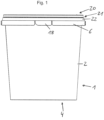
- FIGS 1-6 show an embodiment of a stackable container 1 according to the invention, which according to figure 1 is closed with a lid 20. All characteristics of the container, container stack or container with lid figure 7 can independently or in combination with each other in a container, container stack or container with a lid according to Figures 1 to 6 be realised.
- the stackable container 1 after Figures 1 to 6 has a side wall 2 which forms an upper container edge 3 and completely delimits a container interior for filling with filling material, the container having a container bottom 4 .
- the container cross-section tapers in the direction of the base 4, with the container 1 being stackable with other containers 1 of the same construction, engaging the container base 4 of a first container in a second container.
- the container 1 In the region of the upper edge 3 of the container, the container 1 has a peripheral snap-in edge 5 for snap-in connection with a lid 20 .
- the container locking edge 5 is formed on the side wall 2, wherein an at least substantially completely circumferential container apron 6 is provided on the side wall 2, which radially outwards from of the side wall 2 and which has a section 7, 8 that is at least substantially transverse to the main axis H of the container and a section 7, 8 that is at least substantially parallel to the main axis H of the container.
- the apron 6 is formed on the side wall 2 of the container below the latching edge 5 .
- Ribs 11 are also provided, which are formed on the inside of the skirt 6 and extend essentially in the radial direction of the container 1, these ribs 11 being designed here as stiffening ribs of the skirt 6.
- the container 1 has cooperating first and second anti-rotation means 9,10, wherein when containers 1 are stacked one inside the other, first anti-rotation means 9 of one container interact with second anti-rotation means 10 of the second container, which is stacked in the first container.
- the second anti-rotation means are provided here by the stiffening ribs 11 .
- the first anti-rotation means 9 are provided on the upper side 5a of the container latching edge facing away from the container bottom 4 .
- the first anti-rotation means of the container latching edge 5 are designed as depressions 12 provided on the upper side of the latching edge.
- the container locking edge 5 is formed on the upper edge 3 of the container.
- the depressions 12 of the container latching edge 5b have a smaller radial extension than the latching edge 5.
- the depressions 12 are spaced from the radially outer boundary edge 5b of the latching edge 5.
- the indentations of the locking edge of the container only extend so far in the direction of the container bottom that the indentations end above the radially outer boundary edge of the locking edge.
- the radially outer boundary edge of the locking edge forms with a sealing area on the inside of the Lid skirt has a liquid-tight seal extending all the way around the container.
- the cover apron area which forms the sealing area, surrounds the container on its outside.
- further sealing areas can be provided between container and lid, in particular on the inside of the container side wall, optionally also on the upper edge of the container and/or on the outside of the container, even if this is less preferred.
- a plurality of indentations 12 are provided distributed around the circumference of the container, for example 6 to 8.
- the locking edge depressions 12 preferably have only a small extension in the container peripheral direction, for example ⁇ 5°, ⁇ 2° or ⁇ 1°. As a result, the latching edge 5 is not significantly weakened by the indentations and the stacked containers are positioned exactly when the anti-twist device engages.
- the depression 12 has in each case an at least essentially horizontal bottom 12a, which delimits the depression at the bottom.
- the depressions have lateral boundary surfaces 12b that extend at least substantially vertically.
- the lateral boundary surfaces 12b are each arranged at least essentially in a container main plane H, which contains the container main axis, and therefore extend at least essentially in the radial direction.
- the lateral delimiting surfaces 12b can be flat, whereby the delimiting surfaces of the indentation each come to rest flat on the side surface of the ribs 11 when the indentations 12 and the ribs 11 interact to prevent rotation.
- This configuration of the depressions is generally preferred within the scope of the invention.
- the container apron 6 is attached to the side wall 2 below the container latching edge 5 at a vertical spacing 15 therefrom.
- the apron 6 is arranged with its lower edge 6a above the apron 6 of the container arranged under this container of a container stack.
- the lower edge 6a of the skirt 6 of an upper container ends in relation to the lower container in the space 15 between the container upper edge 3 and the connection 6b of the skirt 6 to the side wall 2 of the lower container.
- the lower edge of the apron 6a of the upper container ends here in relation to the container height in the region of the locking edge 5 of the container stacked under it, or at the same level, in particular at the lower end 5c of the container locking edge.
- the ribs 11 of the apron 6 each have a notch 11a for receiving the container upper edge 3 of the container arranged underneath.
- the lower edge 11b of the rib delimiting the notch 11a lies at the level of the depression 12 on the outside of the container side wall, in particular on the upper edge 3 of the container.
- the container apron 6 has an at least horizontally extending section 7 in the form of a flange, which is formed on the container side wall, and radially outside on the outer circumference of the apron 6 an at least essentially vertically extending section 8 or flange.
- the two sections or flanges 7,8 extend around the circumference of the skirt.
- the lower lid edge 21 of a lid 20 that is snapped onto the container can rest on the horizontal flange 7, which extends at least substantially perpendicularly to the main axis H of the container, or can be arranged at a small distance from it.
- the container 1 is provided with a hinged bracket 16 which can pivot.
- the container apron 6, here the vertical section or flange thereof, has a joint connection 6d for a fastening area of the bracket, here in the form of an opening for receiving a fastening pin at the end area of the bracket.
- the center point M of the articulated connection, through which the pivoting axis of the bracket 16 extends, is arranged in such a way that, when the container is stacked, it is arranged above the upper container edge 3 of the container arranged underneath.
- the container 1 has a tamper-evident closure 18 which indicates that the container has been opened for the first time.
- the tamper-evident closure 18 is designed here as a tab, which is integrated in the container apron 6 here.
- the apron 6 together with the tamper-evident closure 18 extends over the entire circumference of the container.
- the container 1 is designed as a round container, with the container cross-section or the side wall tapering towards the container bottom, as a result of which the container can be stacked in another container of the same construction, forming a container stack according to FIG figure 4 .
- the container side wall and the container bottom are rotationally symmetrical.
- the container 1 and lid 20 are designed as plastic parts, in particular as an injection molded part.
- the cover 20 has a peripheral cover edge 21 which has a peripheral cover skirt 22 radially on the outside, which is provided with a locking edge 23 .
- the locking edges 5, 23 of container 1 and lid 20 cooperate to snap the lid to the container connect to.
- the peripheral boundary edge 5b of the lid latching edge 5 rests in a sealing manner on the inside of the lid skirt 22, forming a sealing area.
- the edge of the lid 21 is designed in the form of a circumferential U-shaped channel which is open at the bottom, ie towards the bottom of the container.
- the radially inner, at least substantially vertical, flange 24 of the edge of the lid is drawn downwards from the top edge 3 of the container and is in sealing contact with the inside of the side wall 2 of the container, whereby a second sealing area is provided, but in general only a sealing area can be provided.
- the container side wall 2 in the area of the upper edge of the container is arranged between the radially inner and radially outer flange of the lid rim, and preferably at the same time held in a press fit.
- the lid locking edge 5 also has a corresponding slope.
- the arrangement of the indentations on the upper side of the container locking edge means that the lid cannot be locked on.
- FIGS Figures 1 to 6 The container with lid or container stack is shown below as an exemplary embodiment figure 7 described. Same features of figure 7 are given the same reference numbers as in FIGS Figures 1 to 6 described unless otherwise indicated in the context.
- the stackable container 1 after figure 7 has a side wall 2 which forms an upper container edge 3 and completely delimits a container interior for filling with filling material, the container having a container bottom 4 .
- the container cross-section tapers in the direction of the base 4, with the container 1 being stackable with other containers 1 of the same construction, engaging the container base 4 of a first container in a second container.
- the container 1 has a peripheral snap-in edge 5 for snap-in connection with a lid 20 .
- the container latching edge 5 is formed on the side wall 2, with an at least substantially completely circumferential container apron 6 being provided on the side wall 2, which protrudes radially outwards from the side wall 2 and which is at least substantially transverse to the main container axis H and at least section 7, 8 which is essentially parallel to the main axis H of the container.
- the apron 6 is formed on the side wall 2 of the container below the latching edge 5 .
- the apron 6 is provided with a constriction 19 for receiving the lower edge of the lid, so that when the lid is snapped on, the lower edge of the lid is arranged radially at the level of the partial section 7a of the at least essentially horizontal apron section 7 .
- the container apron 6 is attached to the side wall 2 below the upper edge 3 of the container at a vertical distance 15 therefrom.
- the apron 6 is arranged with its lower edge 6a above the apron 6 of the container arranged under this container of a container stack.
- the lower edge 6a of the skirt 6 of an upper container ends in relation to the lower container in the upper half of the spacing area 15 between the container upper edge 3 and the connection 6b of the skirt 6 on the side wall 2 of the lower container.
- the lower edge of the apron 6a of the upper container ends in relation to the container height here in the area of the latching edge 5 of the container stacked under it, more precisely at the level of the locking edge 5, in particular at the lower end 5c of the container locking edge.
- the apron of the upper container thus overlaps the locking edge of the lower container completely in its vertical extent. At the same time, this protects the radially outer delimitation or the delimiting edge 5b of the locking edge when transporting a stack of empty containers, for example from the effects of an adjacent stack of containers.
- the skirt also has ribs 11 which are formed on the inside of the skirt 6 and extend essentially in the radial direction of the container 1 , these ribs 11 being designed here as stiffening ribs of the skirt 6 .
- the ribs are here formed on both the at least essentially horizontal section 7 and the at least essentially vertical section 8 of the apron.
- the ribs 11 on the inside of the container skirt run in the radial direction of the container and are also formed on the side wall 4 of the container.
- the ribs 11 of the apron 6 each have a notch 11a for receiving the container upper edge 3 of the container arranged underneath.
- the lower edge 11b of the rib delimiting the notch 11a bears against the locking edge 5 of the container stacked underneath, in particular on the upper container edge 3 and/or on the upper side 5a of the locking edge.
- the lower edge 11b of the ribs can bear against the upper edge 3 of the container in the radial direction of the container. If the container has anti-twist means 12 in the form of indentations in the latching edge 5, ribs with the edge delimiting the notches can engage in the indentation 12 in an anti-twist manner and rest against the rear wall of the indentation and/or the bottom of the same. This also stabilizes the container stack side.
- the container apron 6 has an at least horizontally extending section 7 in the form of a flange, which is formed on the container side wall, and radially outside on the outer circumference of the apron 6 an at least essentially vertically extending section 8 or flange.
- the two sections or flanges 7,8 extend around the circumference of the skirt.
- the lower lid edge 21 of a lid 20 snapped onto the container can rest on the horizontal flange 7, more precisely the radially outer partial area 7a thereof, which extends at least essentially perpendicularly to the main axis H of the container, or be arranged at a small distance from it.
- connection of the apron to the container side wall is spaced from the top edge of this container by a distance A (corresponding to the height of the spacing area 15), the apron having a height H, which is determined by the distance between the upper connection of the apron to the container side wall and the lower edge of the apron is defined.
- the ratio of the said distance A to the apron height H is approx. 2 here.
- the container 1 has an articulated bracket 16 which can pivot.
- the container apron 6, here the vertical section or flange thereof, has a joint connection 6d for a fastening area 16a of the bracket, here in the form of an opening for receiving a fastening pin at the end area of the bracket.
- the fastening means of the bracket thus extends beyond the inside of the apron in the direction of the container side wall.
- the mounting pin of the bracket can be fixed in a snap-in manner on the apron.
- the midpoint M of the articulations, through which extends the pivoting axis V of the bracket 16 is arranged in such a way that, when the container is stacked, it is arranged above the upper container edge 3 of the container arranged underneath. As a result, a sufficient portion of the bracket attachment means has sufficient space above the container locking edge.
Description
Die Erfindung bezieht sich auf einen stapelbaren Behälter gemäß dem Oberbegriff von Anspruch 1.The invention relates to a stackable container according to the preamble of
Derartige Behälter werden vielfältig eingesetzt, beispielsweise auch im Lebensmittelbereich, wobei diese Behälter in hoher Stückzahl hergestellt werden. Bei der Handhabung der Behälter bei einem Etikettier- oder Befüllungsvorgang ist es jedoch oftmals erforderlich, die Behälter von einem ausgerichteten Behälterstapel zu vereinzeln und dann mit einer bestimmten Vorzugsorientierung an der Etikettier- oder Befüllungsstation anzuordnen, um die Etikettierung bzw. Befüllung vorzunehmen. Eine Vorzugsorientierung der Behälter kann beispielsweise dadurch gegeben sein, dass diese einen Originalitätsverschluss und/oder Bügel aufweisen, so dass es gewünscht ist, das Etikett in einer möglichst genauen Umfangsposition an dem Behälter anzubringen, beispielsweise in Bezug auf die Anordnung zu dem Originalitätsverschluss und/oder Bügel. Die Behälter werden jedoch in der Regel einzeln oder in kleinen Gruppen beispielsweise in einer Spritzgussmaschine hergestellt, so dass die Behälter dann, wenn diese zur Erzeugung eines Stapels ineinander gestapelt werden, unterschiedliche Verdrehanordnungen in Bezug auf eine Verdrehung der Behälter um ihre Behälterhauptachse aufweisen können, also beispielsweise nicht sämtliche Originalitätsverschlüsse und/oder Bügel der Behälter des Stapels überei nander angeordnet sind. Dies führt beispielsweise dazu, dass in einer Etikettierstation die Etiketten in unterschiedlicher Lage an dem Behälterumfang zum Originalitätsverschluss oder Bügel angeordnet sind, was optisch nachteilig ist.Such containers are used in many ways, for example in the food sector, and these containers are produced in large numbers. When handling the containers in a labeling or filling process, however, it is often necessary to separate the containers from an aligned stack of containers and then arrange them with a specific preferred orientation at the labeling or filling station in order to carry out the labeling or filling. A preferred orientation of the containers can be given, for example, by the fact that they have a tamper-evident closure and/or clip, so that it is desirable to attach the label to the container in as precise a circumferential position as possible, for example in relation to the arrangement of the tamper-evident closure and/or Hanger. However, the containers are usually produced individually or in small groups, for example in an injection molding machine, so that when the containers are stacked one inside the other to create a stack, they can have different twisting arrangements in relation to a twisting of the containers about their main container axis, i.e for example, not all tamper-evident closures and/or brackets of the containers in the stack are identical are arranged next to each other. This means, for example, that in a labeling station the labels are arranged in different positions on the container circumference relative to the tamper-evident closure or clip, which is optically disadvantageous.
Ferner ist es ein gesteigertes Bedürfnis, Behälter mit möglichst geringem Gewicht herzustellen, um aus ökologischen Gründen Verpackungsgewicht einzusparen.Furthermore, there is an increased need to produce containers with the lowest possible weight in order to save packaging weight for ecological reasons.
Behälter mit Verdrehsicherungsmitteln, welche die Verdrehposition von ineinander gestapelten Behältern zueinander festlegen, sind bereits bekannt. Hierbei kann beispielsweise die Verdrehsicherung an der Oberseite einer Behälterschürze angeformt sein, welche mit Versteifungsrippen eines darüber angeordneten Behälters des Stapels verdrehsichernd zum Angriff kommen. Diese Verdrehsicherungsmittel sind hierbei an einem horizontalen Bereich der Schürze angeformt. Die Schürze kann hierbei einen Originalitätsverschluss aufweisen und gegebenenfalls auch eine Gelenkverbindung zur Befestigung eines lageveränderlichen Bügels an dem Behälter. Diese Behälter weisen jedoch eine vergleichsweise hohe Stapelhöhe auf, wodurch in einem Stapel einer vordefinierten Höhe nur eine gewisse Anzahl von Behältern ineinander gestapelt werden können, und zudem ein vergleichsweise hohes Gewicht. Die hohe Stapelhöhe bedingt zudem hohe Transportkosten bzw. hohen Energieverbrauch beim Transport, da die Ladekapazität eines Transportmittels beschränkt ist.Containers with anti-rotation means, which determine the relative rotational position of containers stacked one inside the other, are already known. In this case, for example, the anti-twist device can be formed on the upper side of a container apron, which comes into contact with stiffening ribs of a container of the stack arranged above it in a torsion-proof manner. These anti-twist means are formed on a horizontal area of the apron. The apron can have a tamper-evident closure and, if necessary, also an articulated connection for attaching a bracket that can be changed in position to the container. However, these containers have a comparatively high stack height, as a result of which only a certain number of containers can be stacked one inside the other in a stack of a predefined height, and they are also comparatively heavy. The high stack height also causes high transport costs and high energy consumption during transport, since the loading capacity of a means of transport is limited.
Die
Die
Die
Der Erfindung liegt die Aufgabe zugrunde, einen stapelbaren Behälter mit Verdrehsicherung gemäß dem Oberbegriff von Anspruch 1 bereitzustellen, welcher ökologisch besonders vorteilhaft ist und welcher insbesondere eine geringe Stapelhöhe und/oder ein geringes Behältergewicht aufweist.The invention is based on the object of providing a stackable container with an anti-twist device according to the preamble of
Diese Aufgabe zur Bereitstellung eines stapelbaren Behälters mit Verdrehsicherung gemäß dem Oberbegriff von Anspruch 1 wird erfindungsgemäß durch einen stapelbaren Behälter gemäß Anspruch 1 gelöst. Vorteilhafte Ausführungsformen ergeben sich aus den Unteransprüchen.This object of providing a stackable container with an anti-twist device according to the preamble of
Erfindungsgemäß sind die ersten Verdrehsicherungsmittel an der von dem Behälterboden abgewandten Oberseite des Behälterrastrandes vorgesehen. Diese ersten Verdrehsicherungsmittel kommen bei ineinander gestapelten baugleichen Behältern verdrehsichernd mit zweiten Verdrehsicherungsmitteln eines darüber angeordneten Behälters des Stapels zum Angriff. Durch die erfindungsgemäße Anordnung der ersten Verdrehsicherungsmittel sind diese unmittelbar im Bereich des oberen Behälterrandes angeordnet, wobei der Behälterrastrand im Bereich der Behälteroberkante angeordnet ist. Hierdurch ist eine besonders geringe Stapelhöhe der baugleichen Behälter gegeben. Sind die zweiten Verdrehsicherungsmittel des Behälters im Bereich der oder an der Behälterschürze angeordnet, so kann die Schürze eine nur vergleichsweise geringe Höhe, d.h. Erstreckung in Richtung der Behälterhauptachse aufweisen, was Behältergewicht einspart. Die zweiten Verdrehsicherungsmittel können an der Außenseite der Behälterwand und/ oder an der Schürze, vorzugsweise der Innenseite der Schürze, angeformt sein. Die zweiten Verdrehsicherungsmittel können den radialen Abstand zwischen Seitenwand und Schürze überbrücken und mit einem Ende an der Seitenwand und dem anderen Ende an der Schürze abgestützt, vorzugsweise angeformt sein. Die zweiten Verdrehsicherungsmittel sind in Bezug auf die Behälterhöhe vorzugsweise nach radial außen hin von der Schürze überdeckt, besonders bevorzugt vollständig überdeckt und somit bei Ansicht des Behälters senkrecht zur Behälterhauptachse nicht sichtbar. Die ersten Verdrehsicherungsmittel können gegebenenfalls als Vorsprung oder Vorsprünge ausgebildet sein, welche sich in Bezug auf die Behälterseitenwand radial nach außen erstrecken und an dem Behälterrastrand angeformt sein können.According to the invention, the first anti-rotation means are provided on the upper side of the container latching edge facing away from the container bottom. In the case of containers of the same construction that are stacked one inside the other, these first anti-rotation means come into action in an anti-rotation manner with second anti-rotation means of a container of the stack arranged above them. Due to the arrangement of the first anti-rotation means according to the invention, these are arranged directly in the area of the upper edge of the container, with the locking edge of the container being arranged in the area of the upper edge of the container. This results in a particularly low stacking height of the identical containers. Are the second anti-rotation means of the container arranged in the area of or on the container apron, the apron can only have a comparatively small height, ie it can extend in the direction of the main axis of the container, which saves container weight. The second anti-twist means can be formed on the outside of the container wall and/or on the skirt, preferably the inside of the skirt. The second anti-twist means can bridge the radial distance between the side wall and the skirt and can be supported with one end on the side wall and the other end on the skirt, preferably molded on. In relation to the height of the container, the second anti-rotation means are preferably covered radially outwards by the apron, particularly preferably completely covered, and are therefore not visible when the container is viewed perpendicularly to the main axis of the container. The first anti-rotation means can optionally be designed as a projection or projections which extend radially outwards in relation to the container side wall and can be formed on the container latching edge.
Als Behälterhauptachse sei hierbei eine Achse verstanden, welche sich über die Höhe des Behälters erstreckt und durch den Mittelpunkt des Behälterbodens sowie der Behälteröffnung verläuft. Sofern der Behälter keinen asymmetrisch angeordneten Bügel aufweist, verläuft die Behälterhauptachse in der Regel auch durch den Behälterschwerpunkt. Der Begriff "vertikale Richtung" sei als Richtung parallel zur Behälterhauptachse verstanden, entsprechend der Begriff "vertikal". Der Begriff "horizontale Richtung" sei als Richtung senkrecht zur Behälterhauptachse verstanden, entsprechend der Begriff "horizontal". Der Begriff "oberhalb" sei als dem Behälterboden abgewandt verstanden, entsprechend der Begriff "oberer" als weiter vom Behälterboden beabstandet, wobei "unterhalb" oder "unten" in entsprechend umgekehrten Sinne zu verstehen sei. Als Stapelhöhe sei im Allgemeinen der vertikale Abstand der Behälteroberkanten von ineinander gestapelten benachbarten Behältern verstanden. Seien in Bezug auf einen "oberen und unteren" Behälter Bezug genommen, so sind diese stets in Bezug auf den Behälterstapel unmittelbar ineinander gestapelt, also die im Stapel nächstbenachbarten Behälter. Die beschriebenen Merkmale beziehen sich jeweils auf denselben Behälter, sofern nicht auf einen oberen und unteren Behälter Bezug genommen wird.The main axis of the container is understood to be an axis which extends over the height of the container and runs through the center point of the container bottom and the container opening. If the container does not have an asymmetrically arranged bracket, the main axis of the container usually also runs through the container's center of gravity. The term "vertical direction" should be understood as a direction parallel to the main axis of the container, corresponding to the term "vertical". The term "horizontal direction" should be understood as a direction perpendicular to the main axis of the container, corresponding to the term "horizontal". The term "above" should be understood as facing away from the container bottom, correspondingly the term "upper" as further spaced from the container bottom, with "below" or "below" in the correspondingly opposite sense to be understood. The stacking height is generally understood to be the vertical distance between the top edges of the containers and adjacent containers that are stacked one inside the other. If reference is made to an "upper and lower" container, these are always stacked directly one inside the other in relation to the container stack, ie the containers next to one another in the stack. The features described each relate to the same container, unless reference is made to an upper and lower container.
Vorzugsweise sind im Bereich der Schürze, besonders bevorzugt an der Innenseite der Schürze Rippen vorgesehen, welche sich vorzugsweise im Wesentlichen in radialer Richtung des Behälters erstrecken und welche vorzugsweise an der Schürze angeformt sind, und wobei die zweiten Verdrehsicherungsmittel vorzugsweise durch diese Rippen bereitgestellt sind. Vorzugsweise sind diese Rippen als Versteifungsrippen der Schürze ausgebildet. Hierdurch können die Rippen, insbesondere als Versteifungsrippen, des eingestapelten Behälters ("oberer Behälter" in Bezug auf den Behälterstapel) eine vergleichsweise geringe Höhe, d.h. Erstreckung in Richtung der Behälterhauptachse, aufweisen, was mit einer signifikanten Gewichtsersparnis verbunden ist. Aufgrund der kürzeren Rippen der Behälter ist zudem die Stapelhöhe der Behälter verringert, da die verkürzten Rippen bedingen, dass die Unterkante dieser Rippen zu der Behälteroberkante einen geringeren Abstand aufweist, als bei herkömmlichen Behältern. Durch die Verringerung der Stapelhöhe können die Transportkosten beim Transport von Behälterstapeln wesentlich verringert werden. Bei ineinander gestapelten Behältern können die Versteifungsrippen des oberen Behälters auf der Behälteroberkante des darunter angeordneten Behälters aufsitzen. Im Folgenden seien die Versteifungsrippen auch als "Rippen" bezeichnet. Die besagten Rippen weisen jeweils bevorzugt eine Versteifungsfunktion in Bezug auf die Schürze auf, was aber allgemein nicht immer zwingend der Fall sein muss. Bevorzugt sind die ersten Verdrehsicherungsmittel unmittelbar an dem Behälterrastrand angeformt, was eine geringe Behälterhöhe und/oder Stapelhöhe der Behälter bedingt.Ribs are preferably provided in the area of the apron, particularly preferably on the inside of the apron, which preferably extend essentially in the radial direction of the container and which are preferably formed on the apron, and the second anti-rotation means are preferably provided by these ribs. These ribs are preferably designed as stiffening ribs of the apron. As a result, the ribs, in particular as stiffening ribs, of the stacked container ("upper container" in relation to the container stack) can have a comparatively small height, ie extension in the direction of the main container axis, which is associated with a significant weight saving. Due to the shorter ribs of the containers, the stacking height of the containers is also reduced, since the shortened ribs mean that the lower edge of these ribs is at a smaller distance from the upper edge of the container than in conventional containers. By reducing the stack height, the transport costs when transporting stacks of containers can be significantly reduced. When containers are stacked one inside the other, the stiffening ribs of the upper container can rest on the top edge of the container arranged underneath. The stiffening ribs are also referred to below as “ribs”. Said ribs each have preferred a stiffening function in relation to the apron, which generally does not always have to be the case. The first anti-rotation means are preferably formed directly on the container latching edge, which results in a low container height and/or stacking height of the containers.
Besonders bevorzugt sind die ersten Verdrehsicherungsmittel des Behälterrastrandes als an der Oberseite des Rastrandes vorgesehene zumindest eine oder mehrere Vertiefungen ausgebildet. Hierdurch wird die Stapelhöhe der Behälter weiter verringert. Ferner wird durch die Ausbildung Verdrehsicherungsmittel an der Oberseite des Rastrandes in Form von Vertiefungen desselben vermieden, dass beim Aufrasten eines Deckels der Aufrastvorgang durch die Verdrehsicherungsmittel des Behälters behindert oder beeinträchtigt wird. Als "Rastrand" im Rahmen der Erfindung sei stets der Rastrand des Behälters verstanden, sofern sich aus dem Zusammenhang im Einzelnen nichts anderes ergibt. Es versteht sich, dass der Deckel mit korrespondieren Rastmitteln versehen ist. Insbesondere können der Rastrand des Behälters und/oder der Rastrand des Deckels vollumfänglich um das jeweilige Bauteil ausgebildet sein.Particularly preferably, the first anti-rotation means of the container locking edge are designed as at least one or more indentations provided on the upper side of the locking edge. This further reduces the stacking height of the containers. Furthermore, the formation of anti-rotation means on the upper side of the latching edge in the form of indentations of the same prevents the latching process from being impeded or impaired by the anti-rotation means of the container when a lid is latched on. Within the context of the invention, the “locking edge” is always understood to be the locking edge of the container, unless the context in detail indicates otherwise. It goes without saying that the cover is provided with corresponding locking means. In particular, the latching edge of the container and/or the latching edge of the lid can be formed around the entire circumference of the respective component.
Bevorzugt sind die Verdrehsicherungsmittel derart ausgebildet, dass bei ineinander gestapelten Behältern, bei welchen die ersten und zweiten Verdrehsicherungsmittel nicht verdrehsichernd zusammenwirken, durch Verdrehung der Behälter gegeneinander um die Behälterhauptachse die ersten und die zweiten Verdrehsicherungsmittel der ineinander gestapelten Behälter miteinander verdrehsichernd zum Eingriff gebracht werden können. Die beiden ineinander gestapelten Behälter sitzen hierbei in der Höhe aufeinander auf. Sind durch die Verdrehung der beiden ineinander gestapelten Behälter die ersten und die zweiten Verdrehsicherungsmittel in Bezug auf die Behälterhöhe bzw. die Stapelrichtung der Behälter übereinander angeordnet, so kommen die Verdrehsicherungsmittel miteinander verdrehsichernd in Eingriff. Sind die ersten Verdrehsicherungsmittel am Rastrand als zumindest eine oder mehrere Vertiefungen ausgebildet, so senken sich die zweiten Verdrehsicherungsmittel des oberen Behälters in die Vertiefung(en) verdrehsichernd ein. Bei der Verdrehung der beiden übereinander gestapelten Behälter gegeneinander, wenn also die beiden Behälter noch nicht in einer verdrehgesicherten Position zueinander angeordnet sind, können hierbei die zweiten Verdrehsicherungsmittel des oberen der beiden Behälter an dem Rastrand des unteren der beiden Behälter geführt sein, also der Rastrand als Führung bei der Verdrehung der Behälter relativ zueinander fungieren, wobei bei dieser Führung die zweiten Verdrehsicherungsmittel des zweiten Behälters auf dem Rastrand des unteren Behälters gleiten können und in Umfangsrichtung des Rastrandes auf diesem aufsitzend gleitend bewegt werden können.The anti-rotation means are preferably designed in such a way that when containers are stacked one inside the other, in which the first and second anti-rotation means do not interact to prevent rotation, the first and second anti-rotation means of the containers stacked in one another can be brought into engagement with one another in an anti-rotation manner by rotating the containers against one another about the main container axis. The two containers stacked one inside the other sit on top of each other in terms of height. Are the first and the second anti-rotation means with respect to the rotation of the two stacked containers the container height or the stacking direction of the containers are arranged one above the other, the anti-rotation means come into engagement with one another in an anti-rotation manner. If the first anti-twist means are designed as at least one or more indentations on the latching edge, the second anti-twist means of the upper container sink into the indentation(s) in an anti-twist manner. When the two containers stacked on top of each other are rotated relative to one another, i.e. if the two containers are not yet arranged in a non-rotating position relative to one another, the second anti-rotation means of the upper of the two containers can be guided on the latching edge of the lower of the two containers, i.e. the latching edge as Guide in the rotation of the containers act relative to each other, with this guide the second anti-rotation means of the second container can slide on the locking edge of the lower container and can be slidably moved in the circumferential direction of the locking edge on this seated.
Durch die erfindungsgemäße Ausbildung des Behälters ist ferner der Bereich der Seitenwand, welcher mit einem Label wie insbesondere einem in-mold-Label ohne Beeinträchtigung des optischen Erscheinungsbildes des Labels versehen werden kann, besonders groß, insbesondere in Bezug auf die Behälterhöhe.Due to the container design according to the invention, the area of the side wall which can be provided with a label such as in particular an in-mold label without impairing the optical appearance of the label is particularly large, in particular with regard to the container height.
Bevorzugt ist der Behälterrastrand an der Behälteroberkante angeformt, insbesondre unmittelbar an dieser. Hierdurch ist die Seitenwand im Bereich der Behälteröffnung durch den Rastrand stabilisiert, wodurch der Behälter vergleichsweise dünnwandig ausgebildet sein kann. Zudem kann der Deckel hierdurch auch eine vergleichsweise geringe Höhe der außenseitigen Deckelschürze aufweisen, welche den Behälter außenseitig übergreift, wobei an der Innenseite der Deckelschürze der vorzugsweise vollständig umlaufende Deckelrastrand angeformt ist. Die Anordnung des Behälterrastrandes unmittelbar an der Behälteroberkante, so dass also die Oberkante bzw. obere Begrenzungslinie des Rastrandes mit der Behälteroberkante abschließt, ist besonders vorteilhaft in Kombination mit der Ausbildung der Verdrehsicherungsmittel als an der Oberseite des Rastrandes vorgesehenen Vertiefungen. Trotz der unmittelbaren Anordnung des Rastrandes an der Behälteroberkante können die Vertiefungen hierdurch eine ausreichende vertikale Erstreckung aufweisen, um einen sicheren Eingriff mit den zweiten Verdrehsicherungsmittel des eingestapelten Behälters beispielsweis den unteren Bereichen bzw. Unterkanten der Versteifungsrippen ausbilden.The container latching edge is preferably formed on the top edge of the container, in particular directly on it. As a result, the side wall is stabilized in the area of the container opening by the latching edge, as a result of which the container can have a comparatively thin-walled design. In addition, as a result, the lid can also have a comparatively small height of the outside lid apron, which overlaps the container on the outside, with the lid apron on the inside the cover locking edge, which is preferably completely circumferential, is integrally formed. The arrangement of the container latching edge directly on the upper edge of the container, so that the upper edge or upper boundary line of the latching edge is flush with the upper edge of the container, is particularly advantageous in combination with the design of the anti-rotation means as depressions provided on the upper side of the latching edge. Despite the direct arrangement of the latching edge on the top edge of the container, the depressions can thus have a sufficient vertical extent to form secure engagement with the second anti-rotation means of the stacked container, for example the lower areas or lower edges of the stiffening ribs.
Bevorzugt weisen die Vertiefungen am Behälterrastrand eine geringere radiale Erstreckung auf, als der Rastrand, wobei die Vertiefungen vom radial außenliegenden Begrenzungsrand des Rastrandes beabstandet sind, also radial innenliegend zu dem Begrenzungsrand des Rastrandes enden. Hierdurch wird die Umfangskontur des Rastrandes somit nicht durch die Vertiefungen beeinträchtigt. Der Begrenzungsrand des Rastrandes kann hierdurch über den gesamten Behälterumfang von der Behälteraußenseite her gesehen konvexe Krümmungen aufweisen. Bei einem Rundbehälter mit kreisförmigen Querschnitten des Behälters kann somit auch die Begrenzungskante des Rastrandes kreisförmig und ohne Einbuchtungen ausgebildet sein. Der radial außenliegende Begrenzungsrand des Rastrandes kann hierdurch als Dichtrand ausgebildet sein, welcher abdichtend mit einem korrespondierenden Dichtungsbereich des Deckels zusammenwirkt. Hierdurch ist in Verbindung mit den oben genannten Vorteilen des Erfindungsgegenstandes zugleich eine hohe Behälterdichtigkeit gegeben. Der Begriff "Vertiefungen" umfasst, dass auch nur eine solche Vertiefung vorgesehen ist, insbesondere sind dies aber mehrere, welche vorzugsweise um den Behälterumfang verteilt angeordnet sind.The indentations on the container locking edge preferably have a smaller radial extension than the locking edge, the indentations being spaced apart from the radially outer boundary edge of the locking edge, ie ending radially on the inside of the boundary edge of the locking edge. As a result, the peripheral contour of the locking edge is not affected by the indentations. As a result, the boundary edge of the latching edge can have convex curvatures over the entire circumference of the container, viewed from the outside of the container. In the case of a round container with circular cross-sections of the container, the boundary edge of the latching edge can therefore also be circular and without indentations. The radially outer delimiting edge of the locking edge can thus be designed as a sealing edge which interacts in a sealing manner with a corresponding sealing area of the cover. In this way, in connection with the above-mentioned advantages of the subject matter of the invention, a high degree of tightness of the container is provided at the same time. The term "depressions" includes the fact that only one such depression is provided, but in particular there are several, which preferably are distributed around the container circumference.
Vorzugsweise erstrecken sich die Vertiefungen des Behälterrastrandes in Bezug auf die Behälterhöhe nur so weit in Richtung auf den Behälterboden, dass die Vertiefungen oberhalb des radial außenliegenden Begrenzungsrandes des Rastrandes enden. Hierdurch kann der Behälterrastrand, insbesondere dessen radial außenliegende Begrenzung, als Dichtrand gegenüber dem Deckel ausgebildet sein, wobei die Vertiefungen zugleich als ausreichend erwiesen haben, um eine Verdrehsicherung bereitzustellen.The indentations of the container latching edge preferably only extend so far in relation to the container height in the direction of the container bottom that the indentations end above the radially outer boundary edge of the latching edge. As a result, the container latching edge, in particular its radially outer limit, can be designed as a sealing edge in relation to the lid, the indentations also having proven to be sufficient to provide anti-twist protection.
Bei dem mit einem Deckel verschlossen Behälter liegt somit besonders bevorzugt der radial außenliegende Begrenzungsrand des Rastrandes an einem Dichtungsbereich des Deckels an, wobei der Begrenzungsrand und der Dichtungsbereich jeweils vorzugsweise vollumfänglich umlaufend um Behälter bzw. Deckel ausgebildet sind. Hierdurch ist vorzugsweise eine vollumfängliche Dichtung zwischen Behälter und Deckel ausgebildet, welche vorzugsweise flüssigkeitsdicht ist. Hierdurch ist es zudem ermöglicht, dass die umlaufende Deckelschürze, welche den Behälter radial außenseitig umgibt und in Zusammenwirkung mit dem Begrenzungsrand des Rastrandes eine Dichtung ausbildet. Zudem kann hierdurch die außenliegende Deckelschürze eine nur geringe Höhe aufweisen, wodurch eine weitere Gewichtsersparnis in Bezug auf das Gebinde aus Behälter und Deckel gegeben ist.In the case of the container closed with a lid, the radially outer delimiting edge of the latching edge is particularly preferably in contact with a sealing area of the lid, the delimiting edge and the sealing area preferably being formed around the full circumference of the container or lid. As a result, a full-circumferential seal is preferably formed between the container and the lid, which is preferably liquid-tight. This also makes it possible for the peripheral cover skirt, which surrounds the container radially on the outside and forms a seal in cooperation with the boundary edge of the latching edge. In addition, as a result, the outer lid apron can only have a small height, which results in a further weight saving in relation to the container and lid bundle.
Bevorzugt liegen die zweiten Verdrehsicherungsmittel des oberen Behälters innerhalb der Vertiefungen am dem oberen Randbereich des unteren Behälters an. Alternativ oder zusätzlich liegen bevorzugt die zweiten Verdrehsicherungsmittel des oberen Behälters an dem radial außenliegenden Begrenzungsrand des Rastrandes des unteren Behälters an. Hierdurch wir die Stabilität eines Behälterstapels mit ineinander eingesetzten Behältern wesentlich erhöht. Sämtliche Ausführungen zu der Erfindung mit zusammenwirkenden ersten und zweiten Verdrehsicherungsmitteln beziehen sich hierbei auf ineinander gestapelte Behälter, also ineinander gestapelte erste und zweite Behälter, sofern sich aus dem Zusammenhang im Einzelnen nichts anderes ergibt.Preferably, the second anti-twist means of the upper container rest within the recesses on the upper edge area of the lower container. Alternatively or additionally, the second anti-rotation means of the upper container are preferably in contact with the radially outer boundary edge of the latching edge of the lower container. Through this we significantly increases the stability of a container stack with containers used one inside the other. All of the statements relating to the invention with interacting first and second anti-rotation means relate here to containers stacked one inside the other, ie first and second containers stacked one inside the other, unless the specific context indicates otherwise.
Die Erfindung betrifft somit allgemein auch einen Behälter mit Deckel. Der Deckel ist an dem Rastrand des Behälters rastend festlegbar, um die Behälteröffnung, welche von der Behälterkante umgrenzt wird, zu verschließen. Der Deckel kann also auch als "Verschlussdeckel" bezeichnet werden. Insbesondere kann der Deckel derart ausgebildet sein, dass dieser einen umlaufenden Deckelbereich in Ausbildung einer nach unten offenen Rinne aufweist, die Rinne also bei auf dem Behälter aufgesetztem Deckel zum Behälterboden hin offen ist. Diese Deckelrinne kann den oberen Behälterrand aufnehmen. Die Behälterkante kann auf dem zumindest im Wesentlichen horizontalen mittleren Abschnitt des genannten U-Profils der Deckelrinne aufsitzen, bei aufgerastetem Deckel. Vorzugsweise weist die Deckelrinne am äußeren Deckelrand einen sich zumindest im Wesentlichen in vertikaler Richtung erstreckenden umlaufenden Flansch auf, welcher dichtend an der Innenseite des Behälters anliegt. Die Behälterseitenwand im Bereich der Behälteroberkante kann hierdurch im Presssitz zwischen dem radial innenliegenden Flansch und dem radial außenliegenden Deckelrand, welcher den Behälter außenseitig umgreift, angeordnet sein, wodurch eine hohe Behälterdichtigkeit und zugleich Stabilität des oberen Behälterbereichs gegeben ist, was bei aufeinander gestapelten befüllten Behältern aufgrund des Behältergewichtes vorteilhaft ist. Gegebenenfalls kann der äußere Deckelrand jedoch auch eine andere Geometrie aufweisen und ist nicht auf die Anordnung einer nach unten offenen Rinne zur Aufnahme der Behälteroberkante beschränkt. Die Ausbildung des Deckelrandes mit nach unten offener U-förmiger Rinne ist jedoch besonders vorteilhaft in Kombination mit der beschriebenen Ausbildung des radial außenliegenden Begrenzungsrandes des Rastrandes als Dichtungsrand, welcher mit einem Dichtungsbereich des Deckels zusammenwirkt, da hierdurch eine hohe Behälterdichtigkeit gewährleistet ist, insbesondere auch, wenn die Behälterseitenwand vergleichsweise dünnwandig ist und daher der Behälter im Bereich des oberen Behälterrandes eben aufgrund dieser Dünnwandigkeit nur eine beschränkte Stabilität aufweist, welche jedoch die gegebenen Erfordernisse erfüllt.The invention thus generally also relates to a container with a lid. The lid is snap-fastenable to the snap-in rim of the container to close the container opening defined by the container rim. The cover can therefore also be referred to as a "closure cover". In particular, the lid can be designed in such a way that it has a circumferential lid area in the form of a groove that is open at the bottom, ie the groove is open towards the bottom of the container when the lid is placed on the container. This cover channel can accommodate the upper edge of the container. The edge of the container can rest on the at least essentially horizontal central section of the aforementioned U-profile of the cover channel when the cover is snapped on. The cover channel preferably has a peripheral flange on the outer edge of the cover which extends at least essentially in the vertical direction and which rests sealingly on the inside of the container. The container side wall in the area of the upper edge of the container can thus be arranged with a press fit between the radially inner flange and the radially outer edge of the lid, which surrounds the container on the outside, whereby a high container tightness and at the same time stability of the upper container area is provided, which is the case when filled containers are stacked on top of each other due to of the container weight is advantageous. If necessary, however, the outer edge of the lid can also have a different geometry and is not limited to the arrangement a downwardly open channel for receiving the upper edge of the container. However, the design of the edge of the lid with a U-shaped channel open at the bottom is particularly advantageous in combination with the described design of the radially outer delimiting edge of the locking edge as a sealing edge, which interacts with a sealing area of the lid, since this ensures a high level of container tightness, especially if the side wall of the container is comparatively thin-walled and therefore the container in the area of the upper container rim has only limited stability precisely because of this thin wall, which, however, fulfills the given requirements.
Bevorzugt sind mehrere um den Behälterumfang verteilt angeordnete erste Verdrehsicherungsmittel an der von dem Behälterboden abgewandten Oberseite des Behälterrandes vorgesehen, insbesondere auch in Ausbildung von Vertiefungen des Behälterrastrandes. Die Verdrehsicherungsmittel sind vorzugsweise gleichmäßig um den Behälterumfang verteilt angeordnet. Hierdurch ist eine erhöhte Verdrehsicherheit von ineinander gestapelten Behältern zueinander gegeben. Beispielsweise können ≥ 3 oder ≥ 6 derartige Verdrehsicherungsmittel vorgesehen sein.A plurality of first anti-rotation means arranged distributed around the container circumference are preferably provided on the upper side of the container edge facing away from the container bottom, in particular also in the formation of depressions in the container latching edge. The anti-twist means are preferably distributed evenly around the circumference of the container. This provides increased security against twisting of containers stacked one inside the other. For example, ≧3 or ≧6 such anti-rotation means can be provided.
Vorzugsweise ist die Behälterschürze unterhalb des Behälterrastrandes in einem vertikalen Abstand zu diesem an der Seitenwand angesetzt, wobei die Schürze mit ihrer Unterkante oberhalb der Schürze des darunter angeordneten Behälters eines Behälterstapels endet. Die Schürze weist hierdurch eine nur vergleichsweise geringe Höhe auf, was eine wesentliche Gewichtsersparnis darstellt. Die Schürzen von ineinander gestapelten benachbarten Behältern kommen somit nicht miteinander zur Anlage oder übergreifen somit einander nicht in der Behälterhöhe. Durch die erfindungsgemäße Anordnung der Verdrehsicherungsmittel an der vom Behälterboden abgewandten Oberseite des Behälterrastrandes ist hierdurch dennoch jedoch eine gute Verdrehsicherheit der ineinander gestapelten Behälter gegeben. Die Schürze an dem Behälter weist hierbei vorzugsweise eine Erstreckung in vertikaler Richtung auf, so dass die Unterkante der Schürze eines oberen Behälters in dem Abstandsbereich zwischen der Anformung der Schürze an der Behälterseitenwand und der Behälteroberkante endet. Vorzugsweise übergreift die Schürze des oberen Behälters den Rastrand des unteren Behälters zumindest teilweise, ist also gegenüber der Behälteroberkante des unteren Behälters nach unten gezogen, also in Richtung auf den Boden des unteren Behälters. Besonders bevorzugt endet die Unterkante der Schürze des oberen Behälters in der oberen Hälfte des genannten Abstandsbereiches des unteren Behälters, also in dem der Behälteroberkante des unteren Behälters zugewandten Hälfte des genannten Abstandsbereichs, weiter bevorzugt im dem oberen Drittel oder dem oberen Viertel des Abstandsbereiches des unteren Behälters. Besonders bevorzugt ist bei ineinander eingestapelten Behältern die Unterkante der Schürze des oberen Behälters im Bereich des Rastrandes des unteren Behälters angeordnet, wobei die Schürze des oberen Behälters vorzugsweise den Rastrand des unteren Behälters in der Höhe vollständig übergreift, besonders bevorzugt im Bereich des unteren Endes oder unmittelbar am unteren Ende des Rastrandes endet. Endet die Unterkante der Schürze des oberen Behälters in Bezug auf die Behälterhöhe im Bereich des Rastrandes des unter diesem gestapelten Behälters, so ist die Unterkante der Schürze vorzugsweise um weniger als der 3-fachen oder weniger als der 2-fachen oder weniger als der 1-fachen oder weniger der 0,5-fachen Wandstärke der Behälterseitenwand, welche unmittelbar unterhalb des Rastrandes gegeben ist, über den Rastrand hinaus in Richtung auf den Behälterboden des unteren Behälters nach unten gezogen. Besonders bevorzugt endet die Schürze des oberen Behälters mit ihrer Unterkante unmittelbar an dem unteren Ende des Rastrandes des unteren Behälters, mit welchem also der Rastrand in die Behälterseitenwand übergeht. Hierdurch weist jeweils die Schürze einerseits eine nur geringe Höhe und somit der Behälter nur ein geringes Gewicht auf. Ferner weisen hierdurch auch die Versteifungsrippen in der Schürze, welche einerseits die Schürze stabilisieren aber andererseits auch als zweite Verdrehsicherungsmittel fungieren, eine nur geringe Höhe auf, was ebenfalls eine Gewichtsersparnis bedingt. Ferner ist hierdurch ein optisch ansprechendes Erscheinungsbild gegeben, da die Schürze den Rastrand überdeckt. Allgemein im Rahmen der Erfindung stehen die Versteifungsrippen an der Innenseite der Schürze in der Höhe nicht über die Unterkante der Schürze in Richtung auf den Behälterboden vor, was sonst optisch unvorteilhaft wäre oder beispielsweise auch eine Reinigung der Außenseite des Behälters erschweren würde. Die erfindungsgemäße Ausgestaltung des Behälters ermöglicht hierbei somit ein sehr geringes Behältergewicht in Verbindung mit einer Verdrehsicherung der Behälter und zueinander und optisch gutem Erscheinungsbild.The container apron is preferably attached to the side wall below the container latching edge at a vertical distance therefrom, with the apron ending with its lower edge above the apron of the container of a stack of containers arranged underneath. As a result, the apron is only comparatively low in height, which represents a significant weight saving. The skirts of adjacent containers stacked in one another therefore do not come into contact with one another or overlap one another in terms of container height. Due to the arrangement according to the invention the anti-twist means on the upper side of the container latching edge facing away from the container bottom, this nevertheless provides good security against twisting of the containers stacked one inside the other. The skirt on the container preferably extends in the vertical direction, so that the bottom edge of the skirt of an upper container ends in the space between the molding of the skirt on the container side wall and the top edge of the container. Preferably, the skirt of the upper container at least partially overlaps the latching edge of the lower container, ie it is pulled down relative to the upper edge of the lower container, ie towards the bottom of the lower container. Particularly preferably, the lower edge of the apron of the upper container ends in the upper half of the specified spacing area of the lower container, i.e. in the half of the specified spacing area facing the upper edge of the lower container, more preferably in the upper third or the upper quarter of the spacing area of the lower container . In the case of containers stacked one inside the other, the lower edge of the apron of the upper container is particularly preferably arranged in the area of the locking edge of the lower container, with the apron of the upper container preferably completely overlapping the locking edge of the lower container, particularly preferably in the area of the lower end or directly ends at the lower end of the locking edge. If the lower edge of the skirt of the upper container ends in relation to the container height in the region of the latching edge of the container stacked below it, the lower edge of the skirt is preferably less than 3 times or less than 2 times or less than 1 times or less than 0.5 times the wall thickness of the container side wall, which is given immediately below the locking edge, pulled down over the locking edge in the direction of the container bottom of the lower container. Particularly the skirt of the upper container preferably ends with its lower edge directly at the lower end of the snap-in edge of the lower container, with which the snap-in edge thus merges into the side wall of the container. As a result, the apron is only small in height and the container is therefore only light in weight. Furthermore, as a result, the stiffening ribs in the apron, which on the one hand stabilize the apron but on the other hand also function as a second anti-twist means, are only of a small height, which also results in a weight saving. Furthermore, this gives a visually appealing appearance, since the apron covers the latching edge. Generally within the scope of the invention, the stiffening ribs on the inside of the skirt do not protrude above the lower edge of the skirt in the direction of the container bottom, which would otherwise be optically unfavorable or, for example, would also make cleaning the outside of the container more difficult. The configuration of the container according to the invention thus enables a very low container weight in connection with an anti-twist protection of the containers and one another and a good optical appearance.
Vorzugsweise sind die Versteifungsrippen an der Innenseite der Schürze an einem zumindest im Wesentlichen vertikalen Flansch der Schürze und einem sich zumindest im Wesentlichen horizontal erstreckenden Flansch der Schürze, welcher an der Behälterseitenwand angeformt ist, angeformt. Die Schürze wird hierdurch besonders stabilisiert und die bevorzugt als Verdrehsicherungsmittel wirkenden Rippen weisen eine hohe Stabilität auf. Vorzugsweise sind die Rippen an der Innenseite der Schürze außenseitig an der Behälterseitenwand angeformt, insbesondere in Kombination mit der oben beschriebenen Ausgestaltung. Hierdurch wird der obere Behälterbereich besonders stabilisiert, aber auch die Versteifungsrippen selber, auch in ihrer Funktion als Verdrehsicherungsmittel. Die Rippen können hierbei an der Unterkante an dem der Seitenwand zugewandten Ende eine Ausklinkung aufweisen, so dass der die Ausklinkung begrenzende Bereich der Unterkante in die als Verdrehsicherungsmittel wirkenden Vertiefungen des Behälterrastrandes eingreifen kann. Die Ausklinkungen der Versteifungsrippen können hierbei den oberen Behälterrand aufnehmen. Bei ineinander gestapelten Behältern können die Unterkanten der Rippen des oberen Behälters auf der Oberseite des Rastrandes im Bereich der jeweiligen Vertiefung bzw. dem Boden der Vertiefung aufsitzen und hierdurch den Behälterstapel stabilisieren. Der Boden der Vertiefung und die Unterkante der Rippe sind hierbei vorzugsweise zumindest im Wesentlichen horizontal, also senkrecht zur Behälterhauptachse, angeordnet, besonders bevorzugt horizontal. Die Unterkante der Rippe kann hierbei linienförmig an dem Rastrand, insbesondere dem Boden der Vertiefung anliegen. Die Unterkante der Rippe, welche die den oberen Behälterrand aufnehmende Rippenausklinkung begrenzt, kann auf Höhe der Vertiefung an der Außenseite der Behälterseitenwand, insbesondere der Behälteroberkante, und/oder an der Oberseite des Rastrandes anliegen. Hierdurch wird der Behälterstapel zusätzlich stabilisiert und die ineinander gestapelten Behälter zueinander zentriert.The stiffening ribs on the inside of the skirt are preferably formed on an at least substantially vertical flange of the skirt and on an at least substantially horizontally extending flange of the skirt, which is formed on the side wall of the container. The apron is particularly stabilized as a result and the ribs, which preferably act as anti-twist means, have a high level of stability. The ribs on the inside of the skirt are preferably formed on the outside of the container side wall, particularly in combination with the embodiment described above. This particularly stabilizes the upper container area, but also the stiffening ribs itself, also in its function as an anti-twist device. The ribs can have a notch on the lower edge at the end facing the side wall, so that the area of the lower edge delimiting the notch can engage in the indentations of the container latching edge that act as anti-rotation means. The notches of the stiffening ribs can accommodate the upper edge of the container. When containers are stacked one inside the other, the lower edges of the ribs of the upper container can rest on the upper side of the latching edge in the area of the respective depression or the bottom of the depression and thereby stabilize the stack of containers. The bottom of the recess and the lower edge of the rib are preferably arranged at least essentially horizontally, ie perpendicular to the main axis of the container, particularly preferably horizontally. The lower edge of the rib can bear linearly against the locking edge, in particular the bottom of the recess. The lower edge of the rib, which delimits the rib notch receiving the upper container edge, can rest at the level of the recess on the outside of the container side wall, in particular the upper edge of the container, and/or on the upper side of the latching edge. As a result, the stack of containers is additionally stabilized and the containers stacked one inside the other are centered.
Vorzugsweise weist der Behälter einen angelenkten und lageveränderlichen, insbesondere verschwenkbaren Bügel auf, wodurch der Transport eines befüllten Gebindes aus Behälter und Deckel erleichtert ist.Preferably, the container has an articulated and position-changeable, in particular pivotable, bracket, which facilitates the transport of a filled bundle of container and lid.
Vorzugsweise weist die Schürze eine Gelenkanbindung für einen Befestigungsbereich des Behälterbügels auf, wobei der Mittelpunkt der Gelenkanbindung bei einem eingestapelten Behälter oberhalb der oberen Behälterkante des darunter angeordneten Behälters angeordnet ist. Die an dem Behälter gegenüberliegenden Mittelpunkte der Gelenkanbindung können hierbei eine Verschwenkachse des Bügels definieren. Hierdurch kann die Schürze eine nur geringe Höhe aufweisen, was eine Gewichtsersparnis bedingt, wobei die geringe Schürzenhöhe maßgeblich auch durch die erfindungsgemäße Anordnung der ersten Verdrehsicherungsmittel ermöglicht ist.The apron preferably has an articulated connection for a fastening area of the container bracket, with the center point of the articulated connection being above the upper container edge of the container arranged underneath when the container is stacked Container is arranged. The center points of the articulated connection that are opposite on the container can define a pivoting axis of the bracket. As a result, the apron can only have a small height, which results in a weight saving, the low apron height also being made possible to a large extent by the arrangement of the first anti-rotation means according to the invention.
Der erfindungsgemäße Behälter ist insbesondere ein Rundbehälter, also mit kreisförmigen Querschnitten. Die Behälterseitenwand und/oder der Behälterboden kann rotationssymmetrisch ausgebildet sein. Der Behälter verjüngt sich ausgehend von seinem oberen Behälterrand in Richtung auf den Behälterboden, was ein Einstapeln von Behältern ermöglicht. Der Behälter kann einen Originalitätsverschluss aufweisen, insbesondere in Form einer an der Schürze vorgesehenen Originalitätslasche, wobei der Originalitätsverschluss vom Behälter zu entfernen oder in seiner Lage zu verändern ist, um eine Fingereingriffsöffnung freizulegen, so dass der untere Deckelrand zum Öffnen des Behälters ergriffen werden kann.The container according to the invention is in particular a round container, ie with circular cross sections. The container side wall and/or the container bottom can be rotationally symmetrical. Starting from its upper container edge, the container tapers towards the container bottom, which enables containers to be stacked. The container may have a tamper-evident closure, particularly in the form of a tamper-evident tab provided on the skirt, the tamper-evident closure being removable from the container or repositioned to expose a finger-entry opening so that the lower rim of the lid can be grasped to open the container.
Vorzugsweise ist der Behälter als Kunststoffbehälter, insbesondere Spritzgussbauteil ausgebildet, was auch für den Deckel jeweils gelten kann. Hierdurch können die Verdrehsicherungsmittel am oberen Behälterrand, insbesondere auch in Ausbildung von Vertiefungen desselben exakt ausgebildet werden, wodurch eine hohe Verdrehsicherheit gegeben ist.The container is preferably designed as a plastic container, in particular an injection-molded component, which can also apply to the lid in each case. As a result, the anti-twist means can be precisely formed on the upper edge of the container, in particular also in the formation of depressions, which means that there is a high degree of security against twisting.
Erfindungsgemäß weist ferner der Behälter des Gebindes aus Behälter und Deckel eine Behälterschürze auf, welche mit ihrer Unterkante oberhalb der Schürze des in einem Behälterstapel darunter, also unmittelbar unter diesem, angeordneten Behälters endet. Es hat sich im Zuge der Erfindung überraschend herausgestellt, dass die Schürzenhöhe signifikant verringert werden kann, ohne die Behälterstabilität in Hinblick auf die verschiedenen Handhabungen des Behälters wesentlich zu beeinträchtigen, wobei zugleich der Behälter hiermit eine geringere Stapelhöhe aufweist, wenn mehrere Behälter ineinander eingesetzt in einem Behälterstapel angeordnet werden. Bei herkömmlichen Behältern ist die Behälterschürze demgegenüber soweit nach unten, d.h. in Richtung auf den Behälterboden, gezogen, dass diese die Schürze des darunter gestapelten Behälters in der Höhe übergreift, was eine vergleichsweise hohe Stapelhöhe und ein vergleichsweise hohes Behältergewicht bedingt. Im Zuge der Erfindung hat es sich jedoch herausgestellt, dass durch die erfindungsgemäße Ausbildung der Schürze die verschiedenen Handhabungen des Behälters bei dessen Herstellung, Transport, Befüllung usw. nicht beeinträchtigt werden und der Behälter die jeweiligen Erfordernisse erfüllt. Dies gilt auch für die Vereinzelung von Behältern in einer Etikettier- und/oder Befüllstation oder wenn die befüllten Behälter gehandhabt werden, was den Transport von befüllten Behältern in einem Behälterstapel und/oder von vereinzelten Behältern durch einen Endverbraucher umfasst. Ferner wird durch erfindungsgemäße Ausbildung der Schürze das Behältergewicht und damit auch der Materialaufwand bzw. das Aufkommen von Verpackungsmaterial bei Verwendung entsprechender Gebinde signifikant verringert. Zudem ist hierdurch ermöglicht, dass bei einer Vereinzelung von Behältern aus einem Stapel ineinander gestapelter Leerbehälter ein Greifer einer entsprechenden Vereinzelungsvorrichtung in den Zwischenraum zwischen den beiden Schürzen übereinander gestapelter Behälter eingreifen kann, um hierdurch beispielsweise den jeweils oberen Behälter eines Behälterstapels zu vereinzeln. Hierdurch ist ein weiterer Handhabungsvorteil gegeben. Ferner weist der erfindungsgemäße Behälter in einem Leerstapel aus ineinander eingesetzten Behältern eine geringere Stapelhöhe auf, so dass in einem vorgegebenen Transportvolumen einer Transporteinrichtung eine größere Anzahl von Behältern transportiert werden kann und sich die Transportkosten verringern. Der erfindungsgemäße Behälter weist somit eine deutlich verbesserte Nachhaltigkeit in Bezug auf dessen Herstellung und Handhabung auf.According to the invention, the container of the bundle of container and lid also has a container skirt, which ends with its lower edge above the skirt of the container arranged in a container stack below, ie directly below this. It has surprisingly turned out in the course of the invention that the apron height is significant can be reduced without significantly impairing the container stability with regard to the various manipulations of the container, at the same time the container hereby having a lower stack height when several containers are inserted into one another and arranged in a container stack. In conventional containers, however, the container apron is pulled down so far, ie in the direction of the container bottom, that it overlaps the apron of the container stacked underneath, which results in a comparatively high stack height and a comparatively high container weight. In the course of the invention, however, it has turned out that the various handlings of the container during its production, transport, filling, etc. are not impaired by the design of the apron according to the invention and the container meets the respective requirements. This also applies to the singulation of containers in a labeling and/or filling station or when the filled containers are handled, which includes the transport of filled containers in a container stack and/or of singulated containers by an end user. Furthermore, the container weight and thus also the cost of materials or the occurrence of packaging material when using corresponding containers is significantly reduced by the inventive design of the apron. In addition, this makes it possible that when containers are separated from a stack of empty containers stacked one inside the other, a gripper of a corresponding separating device can engage in the space between the two skirts of containers stacked on top of one another, in order to separate, for example, the respective upper container of a container stack. This gives a further handling advantage. Furthermore, the container according to the invention has a lower stack height in an empty stack of containers inserted into one another, so that in a given Transport volume of a transport device can be transported a larger number of containers and reduce the transport costs. The container according to the invention thus has significantly improved sustainability with regard to its production and handling.
Besonders bevorzugt ist der erfindungsgemäße Behälter derart ausgebildet, dass die Unterkante der Schürze des oberen Behälters in Bezug auf die Behälterhöhe im Bereich des Rastrandes des unteren Behälters endet. Die Schürze des oberen Behälters kann hierbei auf Höhe des Rastrandes oder geringfügig unterhalb desselben in Bezug auf den zweiten Behälter enden. Andererseits übergreift die Schürze des oberen Behälters den unteren Behälter noch in einem derart großen Ausmaß, dass der Behälterstapel mit ineinander gestapelten baugleichen Behältern nach wie vor eine vergleichsweise hohe Stabilität aufweist. So besteht prinzipiell die Gefahr, dass sich bei einem Behälterstapel die ineinander eingesetzten Behälter in ihrer Lage relativ zueinander ändern, beispielsweise die Behälterhauptachsen der verschiedenen Behälter nicht mehr koaxial zueinander ausgerichtet. Dies könnte beim Transport von Behälterstapeln auch zu einem Umfallen eines Stapels führen oder Probleme bei der Vereinzelung von Behältern aus dem Stapel an einer Etikettier- oder Befülleinrichtung ergeben. Es hat sich jedoch herausgestellt, dass bei dem erfindungsgemäßen Behälter die Schürze des oberen Behälters den unteren Behälter noch um ein ausreichendes Ausmaß in Bezug auf die Behälterhöhe übergreift, so dass diese Gefahr nicht in relevantem Umfang gegeben ist.The container according to the invention is particularly preferably designed in such a way that the lower edge of the skirt of the upper container ends in relation to the container height in the region of the locking edge of the lower container. The skirt of the upper container can then end at the level of the locking edge or slightly below it with respect to the second container. On the other hand, the apron of the upper container still overlaps the lower container to such an extent that the stack of containers with identical containers stacked one inside the other still has a comparatively high stability. In principle, there is a risk that in a stack of containers the position of the containers inserted into one another will change relative to one another, for example the main container axes of the various containers will no longer be aligned coaxially with one another. When transporting stacks of containers, this could also lead to a stack falling over or to problems when separating containers from the stack at a labeling or filling device. However, it has been found that with the container according to the invention the apron of the upper container still overlaps the lower container by a sufficient extent in relation to the container height, so that this risk does not exist to a relevant extent.
Bei dem erfindungsgemäßen Behälter ist somit ein Abstand A zwischen der Behälteroberkante und der oberen Anbindung der Schürze an der Behälterseitenwand gegeben. Ferner weist die Schürze eine Höhe H auf, nämlich den Abstand zwischen der oberen Anbindung der Schürze an der Behälterseitenwand und der Unterkante der Schürze. Bei dem erfindungsgemäßen Behälter liegt das Verhältnis des besagten Abstandes A zu der Schürzenhöhe H vorzugsweise im Bereich von 1,25 bis 3, besonders bevorzugt im Bereich von 1,5 bis 2,5, weiter bevorzugt im Bereich von 1,75 bis 2,25, beispielsweise ca. 2. Hierdurch ist eine besonders günstige Behältergeometrie geschaffen, einerseits in Bezug auf die Stapelhöhe und Gewichtsverringerung des Behälters durch eine verringerte Schürzenhöhe, andererseits im Hinblick auf eine ausreichende Schürzenhöhe, um einen Befestigungsbereich zur sicheren Anlenkung eines Bügels bereitzustellen.In the case of the container according to the invention, there is thus a distance A between the upper edge of the container and the upper connection of the apron to the side wall of the container. Furthermore, the apron has a height H, namely the distance between the upper connection of the apron to the container side wall and the lower edge of the apron. In the case of the container according to the invention, the ratio of said distance A to the skirt height H is preferably in the range from 1.25 to 3, particularly preferably in the range from 1.5 to 2.5, more preferably in the range from 1.75 to 2.25 , for example approx. 2. This creates a particularly favorable container geometry, on the one hand with regard to the stacking height and weight reduction of the container due to a reduced apron height, and on the other hand with regard to a sufficient apron height to provide a fastening area for securely attaching a bracket.
Durch die erfindungsgemäße Ausgestaltung des Behälters kann bei gleicher Wandstärke desselben das Behältergewicht, in Bezug auf einen Behälter ohne Bügel, um ca. 5% oder mehr verringert werden. Unter Berücksichtigung der Tatsache, dass derartige Behälter in sehr hohen Stückzahlen hergestellt werden, und eine Verringerung des Behältergewichtes ein stetes Bedürfnis ist, stellt dies eine bedeutsame Verbesserung dar. Zugleich kann hierdurch die Stapelhöhe des Behälters, d. h. der Abstand von Behälteroberkante zu Behälteroberkante bei unmittelbar ineinander gestapelten Behältern, um ca. 30% verringert werden, wodurch sich das Transportvolumen und damit auch die Transportkosten stark verringern. So können beispielsweise auf einer Standardpalette bei einer gegebenen Stapelhöhe von 880 mm in Bezug auf den Behälterstapel ca. 40% mehr Behälter transportiert werden, als bei herkömmlichen Behältern, bei unverändertem Füllvolumen und/oder unveränderter Gesamthöhe des Behälters.Due to the configuration of the container according to the invention, the container weight can be reduced by approx. 5% or more with the same wall thickness in relation to a container without a handle. Considering the fact that such containers are produced in very large quantities and a reduction in container weight is a constant need, this represents a significant improvement. H. the distance from the upper edge of the container to the upper edge of the container in the case of containers stacked directly one inside the other can be reduced by approx. 30%, which greatly reduces the transport volume and thus also the transport costs. For example, about 40% more containers can be transported on a standard pallet with a given stack height of 880 mm in relation to the container stack than with conventional containers, with the same filling volume and/or unchanged overall height of the container.
Die Behälterschürze weist vorzugsweise an ihrem oberen Bereich in Bezug auf deren vertikale Erstreckung eine Einschnürung auf, welche sich vorzugsweise um den gesamten Umfang der Schürze in Behälterumfangsrichtung erstreckt. Diese Einschnürung ist vorzugsweise derart ausgebildet, dass ein zumindest im Wesentlichen horizontaler Abschnitt der Schürze, mit welchem diese an der Behälterseitenwand angeformt ist, in einen zumindest im Wesentlichen vertikalen Schürzenabschnitt übergeht, an welchen sich dann wiederum ein zumindest im Wesentlichen horizontaler zweiter Schürzenabschnitt anschließt und an diesen ein weiterer zumindest im Wesentlichen vertikaler Schürzenabschnitt. Die jeweiligen Abschnitte können hierbei eine gewisse Neigung zu der horizontalen bzw. vertikalen Richtung aufweisen. Der zweite zumindest im Wesentlichen horizontale Schürzenabschnitt ist hierbei der Deckelunterkante zugewandt, so dass die Deckelunterkante auf diesem Schürzenabschnitt aufsitzen oder geringfügig in Bezug auf die Behälterhöhe von diesem beabstandet sein kann. Der erste zumindest im Wesentlichen vertikale Schürzenabschnitt ist hierbei radial innenseitig zu dem unteren Deckelrandbereich, welcher auch die untere Deckelkante umfasst, angeordnet, so dass durch diesen Schürzenabschnitt ein Eindrücken des unteren Deckelrandbereiches radial nach innen verhindert wird und hierdurch der Deckel insbesondere auch beim Transport von Behältern gesichert ist. So kann es beim Transport von Behältern, insbesondere Stapeln von befüllten Behältern, welche mit dem Deckel verschlossen sind, dazu kommen, dass Behälter benachbarter Stapel aneinander anstoßen oder auch die Randbereiche derselben in unerwünschter Weise aufeinander aufsitzen, was ansonsten zu einem unerwünschten Lösen der Rastverbindung zwischen Behälter und Deckel führen könnte. Der zweite vertikale Schürzenabschnitt ist vorzugsweise mit Anlenkungsbereichen zur Befestigung der Enden eines Bügels versehen, beispielsweise in Form von Durchbrechungen der Behälterschürze, in welche Befestigungsmittel wie Zapfen des jeweiligen Bügelendes eingreifen können. Die vertikale Höhe der Einschnürung kann sich hierbei über ≥ 20% oder ≥ 25% der Schürzenhöhe erstrecken, wodurch der radial äußere Deckelrand des auf dem Behälter aufgerasteten Deckels in besonderer Weise stabilisiert wird. Der erfindungsgemäße Behälter ist hierdurch funktionell vorteilhaft ausgebildet, in Kombination mit den oben genannten Vorteilen.The container apron preferably has a constriction in its upper region in relation to its vertical extension, which preferably extends around the entire circumference of the skirt extends in the container peripheral direction. This constriction is preferably designed in such a way that an at least essentially horizontal section of the apron, with which it is formed on the container side wall, merges into an at least essentially vertical apron section, which in turn is then followed by an at least essentially horizontal second apron section this another at least substantially vertical apron section. The respective sections can have a certain inclination to the horizontal or vertical direction. The second, at least substantially horizontal, skirt section faces the bottom edge of the lid, so that the bottom edge of the lid can rest on this skirt section or be slightly spaced from it in relation to the height of the container. The first, at least substantially vertical, skirt section is arranged radially on the inside of the lower edge area of the lid, which also includes the lower edge of the lid, so that this skirt section prevents the lower edge area of the lid from being pressed in radially inwards, and this prevents the lid from being pressed in, in particular when containers are being transported is secured. When transporting containers, in particular stacks of filled containers that are closed with the lid, it can happen that containers in adjacent stacks bump into one another or that the edge regions of the same rest on one another in an undesirable manner, which would otherwise lead to an undesirable loosening of the snap-in connection between Container and lid could lead. The second vertical apron section is preferably provided with articulation areas for fastening the ends of a bracket, for example in the form of openings in the container apron, into which fastening means such as pins of the respective end of the bracket can engage. The vertical height of the constriction can be ≥ 20% or ≥ 25% of the apron height, whereby the radially outer lid edge of the lid snapped onto the container is stabilized in a special way. As a result, the container according to the invention is designed to be functionally advantageous, in combination with the advantages mentioned above.
Vorzugsweise liegt der untere Rippenrand, welcher die Ausklinkung begrenzt, an der Oberseite des Rastrandes des darunter angeordneten Behälters und/oder der radial außenliegenden Begrenzung des Rastrandes an. Hierdurch wird trotz erfindungsgemäß geringer Schürzenhöhe der Behälterstapel stabilisiert, insbesondere auch dahingehend, dass die Behälterhauptachsen übereinander angeordneter Behälter koaxial zueinander angeordnet sind, auch bei gewisser Kraftausübung auf den Behälterstapel quer zur Behälterhauptachse.The lower edge of the rib, which delimits the notch, preferably lies against the upper side of the locking edge of the container arranged underneath and/or the radially outer delimitation of the locking edge. This stabilizes the stack of containers despite the low apron height according to the invention, in particular to the effect that the main container axes of containers arranged one above the other are arranged coaxially to one another, even when a certain force is exerted on the stack of containers transversely to the main container axis.
Vorzugsweise ist bei horizontal angeordnetem Bügel, welcher an dem Behälter angelenkt ist, die Gelenkachse des Bügels, welche zwischen den beiden Mitten der Bügelanlenkungen an der Schürze verläuft, auf Höhe oder oberhalb der Behälteroberkante des darunter angeordneten Behälters eines Behälterstapels angeordnet. Die in Bevorratungsstellung untere Kante des Bügels steht hierbei vorzugsweise nicht von der Unterkante der Behälterschürze nach unten vor, sondern ist in deren Höhe oder oberhalb derselben angeordnet, was auch allgemein im Rahmen der Erfindung der Fall sein kann. Hierdurch ist andererseits die Anlenkung des Bügels in Bezug auf den jeweiligen Behälter relativ nahe an der Behälteroberkante desselben angeordnet. Die Schürze kann hierbei eine Durchbrechung aufweisen, in welcher ein Befestigungselement des Bügels wie beispielsweise ein zapfenförmiger Vorsprung eingreift, um den lageveränderlichen Bügel an der Schürze festzulegen. Hierdurch kann eine vergleichsweise geringe Stapelhöhe des Behälters ermöglicht werden. Ferner sind hierdurch beim Tragen des Behälters durch Angriff an dem Bügel in seiner Handhabungsstellung günstige Transporteigenschaften in Bezug auf einen beispielsweise befüllten und original verschlossenen Behälter gegeben, da der Schwerpunkt des befüllten Behälters in vertikaler Richtung relativ weit von den Anlenkungen des Bügels beabstandet ist und sich somit eine besonders stabile Lageposition des Behälters ergibt, wenn dieser durch manuellen Angriff an den Bügel durch eine Person getragen wird. Andererseits ist hierdurch das Befestigungsmittel des Bügels, welches die Schürzendurchbrechung durchdringt, bei ineinander gestapelten Behältern zumindest mit der halben Höhe oder mehr als dieser oberhalb der Behälterkante angeordnet, wodurch sich eine geringe Stapelhöhe der Behälter ergibt. Vorzugsweise ist hierbei das Befestigungsmittel des Bügels, insbesondere in Ausbildung eines eine Schürzendurchbrechung durchgreifenden Zapfens, im Wesentlichen oder vollständig oberhalb des radial äußeren Begrenzungsrandes des Behälterrastrandes des jeweils unteren Behälters angeordnet, so dass die Stapelung von Behältern ineinander nicht durch das Befestigungsmittel des Bügels behindert wird. Im Bereich der Unterkante der Behälterschürze können ein oder mehrere nach radial außen gerichtete Vorsprünge vorgesehen sein, welche die zumindest im Wesentlichen horizontale Lage des Bügels in seiner Bevorratungsstellung an dem Behälter definieren.When the bracket is arranged horizontally and is articulated to the container, the hinge axis of the bracket, which runs between the two centers of the bracket articulations on the apron, is preferably arranged at the level of or above the upper edge of the container of a container stack arranged underneath. The lower edge of the bracket in the storage position preferably does not protrude downward from the lower edge of the container apron, but is arranged at or above the latter, which can also be the case generally within the scope of the invention. As a result, on the other hand, the articulation of the bracket in relation to the respective container is arranged relatively close to the upper edge of the container. In this case, the apron can have an opening in which a fastening element of the bracket, such as a pin-shaped projection, engages in order to fix the positionable bracket on the apron. A comparatively low stacking height of the container can hereby be made possible. Furthermore this gives favorable transport properties when carrying the container by gripping the bracket in its handling position in relation to a filled and originally sealed container, for example, since the center of gravity of the filled container is relatively far away from the articulations of the bracket in the vertical direction and is therefore particularly stable position of the container results when it is carried by a person by manually attacking the bracket. On the other hand, this means that the fastening means of the bracket, which penetrates the apron opening, is arranged at least at half the height or more than this above the container edge when the containers are stacked one inside the other, resulting in a low stacking height of the containers. Preferably, the fastening means of the bracket, in particular in the form of a pin extending through an apron opening, is arranged essentially or completely above the radially outer boundary edge of the container locking edge of the lower container in each case, so that the stacking of containers in one another is not prevented by the fastening means of the bracket. In the area of the lower edge of the container apron, one or more radially outwardly directed projections can be provided, which define the at least essentially horizontal position of the bracket in its storage position on the container.
Die Erfindung sei nachfolgend anhand eines Ausführungsbeispiels beschrieben und erläutert. Sämtliche Merkmale des Ausführungsbeispiels seien unabhängig voneinander oder in Kombination miteinander allgemein im Rahmen der Erfindung offenbart. Es zeigen:
- Figur 1:
- Seitenansicht eines erfindungsgemäßen Behälters, welcher ferner mit einem Deckel verschlossen ist,
- Figur 2:
- Seitenansicht eines erfindungsgemäßen Behälters,
- Figur 3:
- Perspektivische Ansicht eines Teilbereichs des Behälters nach
Figur 2 , - Figur 4:
- Stapel aus Behältern gemäß
Figur 2 im Aufriss, - Figur 5:
- Schnittdarstellung ineinander gestapelter Behälter nach
Figur 2 , - Figur 6:
- Schematische Darstellung des Verbindungsbereichs eines Behälters gemäß
Figur 2 mit Deckel. - Figur 7:
- eine Querschnittsteildarstellung von ineinander gestapelten erfindungsgemäßen Behältern.
- Figure 1:
- Side view of a container according to the invention, which is also closed with a lid,
- Figure 2:
- Side view of a container according to the invention,
- Figure 3:
- Perspective view of a portion of the container
figure 2 , - Figure 4:
- Stacks of containers according to
figure 2 in outline, - Figure 5:
- Sectional view of stacked containers
figure 2 , - Figure 6:
- Schematic representation of the connection area of a container according to
figure 2 with lid. - Figure 7:
- a partial cross-sectional view of nested containers according to the invention.
Die
Der stapelbare Behälter 1 nach den
Erfindungsgemäß sind die ersten Verdrehsicherungsmittel 9 an der vom Behälterboden 4 abgewandten Oberseite 5a des Behälterrastrandes vorgesehen. Die ersten Verdrehsicherungsmittel des Behälterrastrandes 5 sind nach der besonderen Ausführungsform als an der Oberseite des Rastrandes vorgesehene Vertiefungen 12 ausgebildet. Der Behälterrastrand 5 ist an der Behälteroberkante 3 angeformt. Die Vertiefungen 12 des Behälterrastrandes 5b weisen eine geringere radiale Erstreckung auf als der Rastrand 5. Die Vertiefungen 12 sind vom radial außenliegenden Begrenzungsrand 5b des Rastrandes 5 beabstandet. Die Vertiefungen des Behälterrastrandes erstrecken sich in Bezug auf die Behälterhöhe nur so weit in Richtung auf den Behälterboden, dass die Vertiefungen oberhalb des radial außenliegenden Begrenzungsrandes des Rastrandes enden. Der radial außenliegenden Begrenzungsrand des Rastrandes bildet mit einem Dichtbereich an der Innenseite der Deckelschürze eine flüssigkeitsdichte, sich vollumfänglich um den Behälter erstreckende Dichtung auf. Der Deckelschürzenbereich, welcher den Dichtbereich ausbildet, umfasst den Behälter an dessen Außenseite. Neben diesem Dichtbereich können weitere Dichtungsbereiche zwischen Behälter und Deckel gegeben sein, insbesondere an der Innenseite der Behälterseitenwand, gegebenenfalls zusätzlich auch an der Behälteroberkante und/oder an der Behälteraußenseite, auch wenn dies weniger bevorzugt ist.According to the invention, the first anti-rotation means 9 are provided on the upper side 5a of the container latching edge facing away from the
Es sind mehrere um den Behälterumfang verteilt angeordnete Vertiefungen 12 vorgesehen, beispielsweise 6 bis 8.A plurality of
Die Rastrandvertiefungen 12 weisen in Behälterumfangsrichtung vorzugsweise eine nur geringe Ausdehnung auf, beispielsweise ≤ 5°, ≤ 2° oder ≤ 1°. Hierdurch wird der Rastrand 5 durch die Vertiefungen nicht wesentlich geschwächt und eine exakte Lageanordnung der gestapelten Behälter bei Eingriff der Verdrehsicherung gegeben. Die Vertiefung 12 weist jeweils einen zumindest im Wesentlichen horizontalen Boden 12a auf, welcher die Vertiefung nach unten begrenzt. Die Vertiefungen weisen sich zumindest im Wesentlichen vertikal erstreckende seitliche Begrenzungsflächen 12b auf. Die seitlichen Begrenzungsflächen 12b sind zumindest im Wesentlichen jeweils in einer Behälterhauptebene H angeordnet, welche die Behälterhauptachse beinhaltet, erstrecken sich also zumindest im Wesentlichen in radialer Richtung. Die seitlichen Begrenzungsflächen 12b können eben ausgebildet sein, wodurch die Begrenzungsflächen der Vertiefung jeweils flächig mit der Seitenfläche der Rippen 11 zur Anlage kommen, wenn die Vertiefungen 12 und die Rippen 11 verdrehsichernd zusammenwirken. Diese Ausgestaltung der Vertiefungen ist Allgemein im Rahmen der Erfindung bevorzugt.The locking
Die Behälterschürze 6 ist unterhalb des Behälterrastrandes 5 in einem vertikalen Abstand 15 zu diesem an der Seitenwand 2 angesetzt. Die Schürze 6 ist mit ihrer Unterkante 6a oberhalb der Schürze 6 des unter diesen Behälter angeordneten Behälters eines Behälterstapels angeordnet. Bei ineinander eingestapelten baugleichen Behältern 1 endet die Unterkante 6a der Schürze 6 eines oberen Behälters in Bezug auf den unteren Behälter in dem Abstandsbereich 15 zwischen der Behälteroberkante 3 und der Anbindung 6b der Schürze 6 an der Seitenwand 2 des unteren Behälters. Die Unterkante der Schürze 6a des oberen Behälters endet in Bezug auf die Behälterhöhe hier im Bereich des Rastrandes 5 des unter diesem gestapelten Behälters, bzw. auf Höhe desselben, im speziellen an dem unteren Ende 5c des Behälterrastrandes.The
Die Rippen 11 der Schürze 6 weisen jeweils eine Ausklinkung 11a zur Aufnahme der Behälteroberkante 3 des darunter angeordneten Behälters auf. Die die Ausklinkung 11a begrenzende Unterkante 11b der Rippe liegt auf Höhe der Vertiefung 12 an der Außenseite der Behälterseitenwand an, im Speziellen an der Behälteroberkante 3.The
Die Behälterschürze 6 weist einen sich zumindest horizontal erstreckenden Abschnitt 7 in Form eines Flansches auf, welcher an der Behälterseitenwand angeformt ist, sowie radial außenseitig am Außenumfang der Schürze 6 einen sich zumindest im Wesentlichen vertikal erstreckenden Abschnitt 8 bzw. Flansch. Die beiden Abschnitte bzw. Flansche 7,8 erstrecken sich um die Umfangserstreckung der Schürze. Der untere Deckelrand 21 eines rastend an dem Behälter festgelegten Deckels 20 kann hierbei an dem horizontalen Flansch 7, welcher sich zumindest im Wesentlichen senkrecht zur Behälterhauptachse H erstreckt, aufsitzen oder in geringem Abstand zu diesem angeordnet sein.The
Der Behälter 1 ist mit einem angelenkten, verschwenkbaren Bügel 16 versehen. Die Behälterschürze 6, hier der vertikale Abschnitt bzw. Flansch derselben, weist eine Gelenkanbindung 6d für einen Befestigungsbereich des Bügels auf, hier in Form einer Durchbrechung zur Aufnahme eines Befestigungszapfens am Endbereich des Bügels. Der Mittelpunkt M der Gelenkverbindung, durch welchen sich die Verschwenkachse des Bügels 16 erstreckt, ist derart angeordnet, dass diese bei einem eingestapelten Behälter oberhalb der oberen Behälterkante 3 des darunter angeordneten Behälters angeordnet ist.The
Der Behälter 1 weist einen Originalitätsverschluss 18 auf, welcher ein erstmaliges Öffnen des Behälters anzeigt. Der Originalitätsverschluss 18 ist hier als Lasche ausgebildet, welche hier in der Behälterschürze 6 integriert ist. Die Schürze 6 zusammen mit dem Originalitätsverschluss 18 erstreckt sich über den gesamten Behälterumfang.The
Der Behälter 1 ist als Rundbehälter ausgebildet, wobei sich der Behälterquerschnitt bzw. die Seitenwand zum Behälterboden hin verjüngt, wodurch der Behälter in einen baugleichen anderen Behälter einstapelbar ist, unter Ausbildung eines Behälterstapels gemäß
Der Behälter 1 und Deckel 20 sind als Kunststoffteile ausgeführt, insbesondere als Spritzgussteil.The
Wie in
Im Folgenden sei als Ausführungsbeispiel der Behälter mit Deckel bzw. Behälterstapel nach
Der stapelbare Behälter 1 nach
Der Behälterquerschnitt verjüngt sich in Richtung zum Boden 4 hin, wobei der Behälter 1 mit baugleichen anderen Behältern 1 unter Eingriff des Behälterbodens 4 eines ersten Behälters in einen zweiten Behälter stapelbar ist. Der Behälter 1 weist im Bereich der Behälteroberkante 3 einen umlaufenden Rastrand 5 zur rastenden Verbindung mit einem Deckel 20 auf. Der Behälterrastrand 5 ist an der Seitenwand 2 angeformt, wobei an der Seitenwand 2 eine zumindest im Wesentlichen vollständig umlaufende Behälterschürze 6 vorgesehen ist, welche radial nach außen von der Seitenwand 2 vorsteht und welche einen sich zumindest im Wesentlichen quer zur Behälterhauptachse H und einen sich zumindest im Wesentlichen parallel zur Behälterhauptachse H aufweisenden Abschnitt 7, 8 aufweist. Die Schürze 6 ist unterhalb des Rastrandes 5 an der Behälterseitenwand 2 angeformt. Die Schürze 6 ist mit einer Einschnürung 19 zur Aufnahme des unteren Deckelrandes versehen, so dass bei aufgerastetem Deckel die Deckelunterkante radial auf Höhe der des Teilabschnittes 7a des zumindest im Wesentlichen horizontalen Schürzenabschnittes 7 angeordnet ist.The container cross-section tapers in the direction of the
Die Behälterschürze 6 ist unterhalb der Behälteroberkante 3 in einem vertikalen Abstand 15 zu diesem an der Seitenwand 2 angesetzt. Die Schürze 6 ist mit ihrer Unterkante 6a oberhalb der Schürze 6 des unter diesen Behälter angeordneten Behälters eines Behälterstapels angeordnet. Bei ineinander eingestapelten baugleichen Behältern 1 endet die Unterkante 6a der Schürze 6 eines oberen Behälters in Bezug auf den unteren Behälter in der oberen Hälfte des Abstandsbereichs 15 zwischen der Behälteroberkante 3 und der Anbindung 6b der Schürze 6 an der Seitenwand 2 des unteren Behälters. Die Unterkante der Schürze 6a des oberen Behälters endet in Bezug auf die Behälterhöhe hier im Bereich des Rastrandes 5 des unter diesem gestapelten Behälters, genauer auf Höhe des Rastrandes 5, im speziellen an dem unteren Ende 5c des Behälterrastrandes. Die Schürze des oberen Behälters übergreift also den Rastrand des unteren Behälters vollständig in seiner vertikalen Erstreckung. Hierdurch wird zugleich die radial äußere Begrenzung bzw. der Begrenzungsrand 5b des Rastrandes beim Transport eines Stapels von Leerbehältern geschützt, beispielsweise vor Einwirkung eines benachbarten Behälterstapels.The
Die Schürze weist ferner Rippen 11 auf, welche an der Innenseite der Schürze 6 angeformt sind und sich im Wesentlichen in radialer Richtung des Behälters 1 erstrecken, wobei diese Rippen 11 hier als Versteifungsrippen der Schürze 6 ausgebildet sind. Die Rippen sind hier sowohl an dem zumindest im Wesentlichen horizontalen Abschnitt 7 und dem zumindest im Wesentlichen vertikalen Abschnitt 8 der Schürze angeformt. Die Rippen 11 an der Innenseite der Behälterschürze verlaufen in radialer Richtung des Behälters und sind auch an der Behälterseitenwand 4 angeformt.The skirt also has
Die Rippen 11 der Schürze 6 weisen jeweils eine Ausklinkung 11a zur Aufnahme der Behälteroberkante 3 des darunter angeordneten Behälters auf. Die die Ausklinkung 11a begrenzende Unterkante 11b der Rippe liegt an dem Rastrand 5 des darunter gestapelten Behälters an, im Speziellen an der Behälteroberkante 3 und/oder an der Oberseite 5a des Rastrandes. Insbesondere kann die Rippenunterkante 11b in radialer Richtung des Behälters an der Behälteroberkante 3 anliegen. Weist der Behälter Verdrehsicherungsmittel 12 in Form von Vertiefungen des Rastrandes 5 auf, so können Rippen mit dem die Ausklinkungen begrenzenden Rand verdrehsichernd in die Vertiefung 12 eingreifen und an der Rückwand der Vertiefung und/oder dem Boden derselben anliegen. Hierdurch wird zugleich der Behälterstapelseite stabilisiert.The
Die Behälterschürze 6 weist einen sich zumindest horizontal erstreckenden Abschnitt 7 in Form eines Flansches auf, welcher an der Behälterseitenwand angeformt ist, sowie radial außenseitig am Außenumfang der Schürze 6 einen sich zumindest im Wesentlichen vertikal erstreckenden Abschnitt 8 bzw. Flansch. Die beiden Abschnitte bzw. Flansche 7,8 erstrecken sich um die Umfangserstreckung der Schürze. Der untere Deckelrand 21 eines rastend an dem Behälter festgelegten Deckels 20 kann hierbei an dem horizontalen Flansch 7, genauer dem radial äußeren Teilbereich 7a desselben, welcher sich zumindest im Wesentlichen senkrecht zur Behälterhauptachse H erstreckt, aufsitzen oder in geringem Abstand zu diesem angeordnet sein.The
Die Anbindung der Schürze an der Behälterseitenwand ist hier von der Behälteroberkante dieses Behälters mit dem Abstand A (entsprechend der Höhe des Abstandbereiches 15) beabstandet, wobei die Schürze eine Höhe H aufweist, welche durch den Abstand zwischen der oberen Anbindung der Schürze an der Behälterseitenwand und der Unterkante der Schürze definiert ist. Das Verhältnis des besagten Abstandes A zu der Schürzenhöhe H beträgt hier ca. 2.The connection of the apron to the container side wall is spaced from the top edge of this container by a distance A (corresponding to the height of the spacing area 15), the apron having a height H, which is determined by the distance between the upper connection of the apron to the container side wall and the lower edge of the apron is defined. The ratio of the said distance A to the apron height H is approx. 2 here.
Der Behälter 1 weist einen angelenkten, verschwenkbaren Bügel 16 auf. Die Behälterschürze 6, hier der vertikale Abschnitt bzw. Flansch derselben, weist eine Gelenkanbindung 6d für einen Befestigungsbereich 16a des Bügels auf, hier in Form einer Durchbrechung zur Aufnahme eines Befestigungszapfens am Endbereich des Bügels. Das Befestigungsmittel des Bügels erstreckt sich also über die Innenseite der Schürze hinaus in Richtung auf die Behälterseitenwand. Der Befestigungszapfen des Bügels kann rastend an der Schürze festgelegt sein. Der Mittelpunkt M der Gelenkverbindungen, durch welche sich die Verschwenkachse V des Bügels 16 erstreckt, ist derart angeordnet, dass diese bei einem eingestapelten Behälter oberhalb der oberen Behälterkante 3 des darunter angeordneten Behälters angeordnet ist. Hierdurch hat ein ausreichender Teilbereich des Bügelbefestigungsmittels oberhalb des Behälterrastrandes ausreichend Platz.The
Claims (15)
- Stackable container, which has a side wall (2), which forms an upper container edge (3) and completely delimits a container interior for filling the filling material, the container (1) having a container base (4) and the container cross section tapering in the direction towards the base (4), so that the container (1) can be stacked with other containers (1) of identical construction with engagement of the container base (4) of a first container in a second container, wherein an at least substantially completely circumferential container skirt (6) is provided on the side wall (2), which skirt projects radially outwardly from the side wall (2) and which has a section (7, 8) extending at least substantially transversely to the container main axis (H) and a section (7, 8) extending at least substantially parallel to the container main axis (H), the container (1) further having cooperating first and second anti-rotation means (9, 10), wherein, in the case of containers stacked one inside the other, first anti-rotation means (9) of the one container cooperate with second anti-rotation means (10) of the second container of identical construction stacked in the first container with respect to the containers in such a way as to prevent rotation, characterized in that the container has, in the region of the container top edge (4), a circumferential container latching rim (5) for latching connection to a lid, in that the container latching rim (5) is molded to the side wall (2), in that the skirt (6) is molded to the side wall (2) beneath the container latching rim (5), and in that the first anti-rotation means (9) are provided on the upper side (5a) of the container latching rim (5) facing away from the container base (4).
- Container according to claim 1, characterized in that ribs (11) are provided on the inner side of the skirt (6), which ribs extend substantially in the radial direction of the container (1), and in that the second anti-rotation means (10) are provided by the ribs (11).
- Container according to claim 1 or 2, characterized in that the first anti-rotation means (9) of the container latching rim (5) are formed as a recess or a plurality of recesses (12) provided on the upper side (5a) of the latching rim (5).
- Container according to any one of claims 1 to 3, characterized in that the container upper edge (3).
- Container according to claim 3, preferably also according to one of claims 2 and 4, characterized in that the recesses (12) of the container latching rim (5) have a smaller radial extent than the latching rim (5) and in that the recesses are spaced from the radially outer boundary edge (5b) of the latching rim.
- Container according to claim 3, preferably also according to one of claims 2, 4 and 5, characterized in that the recesses (12) of the container latching rim (5) terminate above the radially outer boundary edge (5b) of the latching rim with respect to the container height.
- Container according to any one of claims 1 to 6, characterized in that the radially outer boundary edge (5b) of the latching rim is designed as a sealing edge which, when the lid (20) is placed on the container (1), forms a preferably liquid-tight container seal with said lid.
- Container according to claim 3, preferably also according to one of claims 2 and 4 to 7, characterized in that the second anti-rotation means (10) of the upper container are applied against the upper edge region of the lower container within the recesses (12) and/or that the second anti-rotation means (10) of the upper container are applied against the radially outer boundary edge of the latching rim of the lower container.
- Container according to claim 3, preferably also according to one of claims 2 and 4 to 8, characterized in that the plurality of recesses (12) are arranged distributed around the container circumference.
- Container according to any one of claims 1 to 9, characterized in that the container skirt (6) is attached to the side wall (2) below the container latching rim (5) at a vertical distance therefrom, and in that, in the case of containers of identical construction stacked one inside the other, the skirt (6) of the upper container is arranged with its lower edge (6a) above the skirt (6) of the lower container (1) of the stack of containers.
- Container according to claim 10, characterized in that the container is designed in such a way that when containers of identical construction are stacked one inside the other, the lower edge (6a) of the skirt (6) of an upper container terminates in the upper half of the vertical distance region (15) between the container upper edge (3) and the connection (6b) of the skirt (6) to the lateral wall (2) of the lower container (1), with respect to the lower container (1).
- Container according to claim 11, characterized in that the lower edge (6a) of the skirt (6) of the upper container (1) terminates in the region of the latching rim (5) of the container (1) stacked below it, preferably at the level of the lower end (5a) of the latching rim (5), with respect to the container height.
- Container according to any one of claims 1 to 12, characterized in that the container (1) is provided with a hinged pivoting bracket (16).
- Container according to claim 13, characterized in that the container skirt (6) includes a joint connection (6d) for an attachment portion of the bracket (16) and in that the center (M) of the joint connection through which the pivot axis of the bracket extends is arranged such that the same is arranged above the upper container edge (3) of the container (1) arranged underneath when the container (1) is stacked.
- Container according to any one of claims 1 to 14, comprising a lid (20) fixable to the container in a latching and preferably sealing manner.
Applications Claiming Priority (3)
| Application Number | Priority Date | Filing Date | Title |
|---|---|---|---|
| DE202018105911.4U DE202018105911U1 (en) | 2018-10-16 | 2018-10-16 | Stackable container |
| DE202018105909.2U DE202018105909U1 (en) | 2018-10-16 | 2018-10-16 | Stackable container |
| PCT/EP2019/078077 WO2020079076A2 (en) | 2018-10-16 | 2019-10-16 | Stackable container |
Publications (3)
| Publication Number | Publication Date |
|---|---|
| EP3867166A2 EP3867166A2 (en) | 2021-08-25 |
| EP3867166B1 true EP3867166B1 (en) | 2023-07-19 |
| EP3867166C0 EP3867166C0 (en) | 2023-07-19 |
Family
ID=68342891
Family Applications (1)
| Application Number | Title | Priority Date | Filing Date |
|---|---|---|---|
| EP19794100.8A Active EP3867166B1 (en) | 2018-10-16 | 2019-10-16 | Stackable container |
Country Status (4)
| Country | Link |
|---|---|
| EP (1) | EP3867166B1 (en) |
| ES (1) | ES2956335T3 (en) |
| PL (1) | PL3867166T3 (en) |
| WO (1) | WO2020079076A2 (en) |
Family Cites Families (9)
| Publication number | Priority date | Publication date | Assignee | Title |
|---|---|---|---|---|
| DK144239C (en) * | 1978-08-24 | 1982-06-21 | Superfos Emballage As | PACKAGING PENALTY |
| NL1005791C2 (en) * | 1997-04-11 | 1998-10-19 | H K Plastics B V | Plastic bucket. |
| US6619498B2 (en) * | 2000-01-27 | 2003-09-16 | Von Holdt, Jr. John W. | Plastic container and lid construction |
| DE10038386C2 (en) * | 2000-08-07 | 2002-11-07 | Grt Verpackungen Aus Kunststof | Plastic container and method and device for its production |
| US20020148846A1 (en) * | 2001-04-12 | 2002-10-17 | Ropak Corporation | Container lid having gasketless liquid seal |
| CA2474312A1 (en) * | 2003-07-17 | 2005-01-17 | John W. Von Holdt, Jr. | Plastic container and lid construction |
| US20060278553A1 (en) * | 2005-06-13 | 2006-12-14 | Plastican, Inc. | Nestable pails with nesting alignment means |
| US20090294322A1 (en) * | 2008-06-02 | 2009-12-03 | Baltz Kyle L | Pail with skirt and lid |
| US10597191B2 (en) * | 2017-02-28 | 2020-03-24 | Yeti Coolers, Llc | Portable container and container assembly |
-
2019
- 2019-10-16 ES ES19794100T patent/ES2956335T3/en active Active
- 2019-10-16 WO PCT/EP2019/078077 patent/WO2020079076A2/en unknown
- 2019-10-16 EP EP19794100.8A patent/EP3867166B1/en active Active
- 2019-10-16 PL PL19794100.8T patent/PL3867166T3/en unknown
Also Published As
| Publication number | Publication date |
|---|---|
| WO2020079076A3 (en) | 2020-07-02 |
| EP3867166C0 (en) | 2023-07-19 |
| EP3867166A2 (en) | 2021-08-25 |
| ES2956335T3 (en) | 2023-12-19 |
| PL3867166T3 (en) | 2023-12-11 |
| WO2020079076A2 (en) | 2020-04-23 |
Similar Documents
| Publication | Publication Date | Title |
|---|---|---|
| EP3995410B1 (en) | Combination of container neck and undetachable closure with stabilized opening angle | |
| DE60214501T2 (en) | Guaranteed closure and container with provisions for draining liquids and process for their preparation | |
| DE3043899C2 (en) | ||
| DE3734156C2 (en) | Two flap closure | |
| EP1268295B1 (en) | Plastic container comprising a locking lid and a sealing rib located inside the container | |
| DE69333254T2 (en) | tamper-evident closure | |
| DE69630596T2 (en) | ORIGINAL CLOSURE WITH GUARANTEE BAND | |
| DE3640040C3 (en) | Packaging containers for liquids | |
| DE2714616A1 (en) | AGAINST TREATMENT CAP | |
| DE202020100758U1 (en) | Captive closure with stabilized opening angle | |
| CH716857A2 (en) | Container closure. | |
| WO1999039982A2 (en) | Paint container | |
| DE3433533A1 (en) | DEVICE FOR STORING AND DELIVERING A VOLATILE SUBSTANCE OR VOLATILE COMPOUNDS | |
| WO2009152798A1 (en) | Container with lid | |
| EP3867166B1 (en) | Stackable container | |
| WO1989007553A1 (en) | Mouth of a container for flowing materials | |
| WO2021018772A1 (en) | Captive closure having a stabilized opening angle | |
| WO2003013968A1 (en) | Container with a cover | |
| DE202018105911U1 (en) | Stackable container | |
| EP3552983B1 (en) | Container with locking ring for securing a lid for transport | |
| EP0387302B1 (en) | Tamper-proof closure | |
| DE102015108403B3 (en) | Beverage can closure and can unit made of beverage can and closure | |
| DE102020126474B3 (en) | Container with an openable lid | |
| DE4306976A1 (en) | Injection-moulded plastic bucket | |
| EP4061736B1 (en) | Container closure |
Legal Events
| Date | Code | Title | Description |
|---|---|---|---|
| STAA | Information on the status of an ep patent application or granted ep patent |
Free format text: STATUS: UNKNOWN |
|
| STAA | Information on the status of an ep patent application or granted ep patent |
Free format text: STATUS: THE INTERNATIONAL PUBLICATION HAS BEEN MADE |
|
| STAA | Information on the status of an ep patent application or granted ep patent |
Free format text: STATUS: THE INTERNATIONAL PUBLICATION HAS BEEN MADE |
|
| PUAI | Public reference made under article 153(3) epc to a published international application that has entered the european phase |
Free format text: ORIGINAL CODE: 0009012 |
|
| STAA | Information on the status of an ep patent application or granted ep patent |
Free format text: STATUS: REQUEST FOR EXAMINATION WAS MADE |
|
| 17P | Request for examination filed |
Effective date: 20210510 |
|
| AK | Designated contracting states |
Kind code of ref document: A2 Designated state(s): AL AT BE BG CH CY CZ DE DK EE ES FI FR GB GR HR HU IE IS IT LI LT LU LV MC MK MT NL NO PL PT RO RS SE SI SK SM TR |
|
| DAV | Request for validation of the european patent (deleted) | ||
| DAX | Request for extension of the european patent (deleted) | ||
| GRAP | Despatch of communication of intention to grant a patent |
Free format text: ORIGINAL CODE: EPIDOSNIGR1 |
|
| STAA | Information on the status of an ep patent application or granted ep patent |
Free format text: STATUS: GRANT OF PATENT IS INTENDED |
|
| INTG | Intention to grant announced |
Effective date: 20230207 |
|
| GRAS | Grant fee paid |
Free format text: ORIGINAL CODE: EPIDOSNIGR3 |
|
| GRAA | (expected) grant |
Free format text: ORIGINAL CODE: 0009210 |
|
| STAA | Information on the status of an ep patent application or granted ep patent |
Free format text: STATUS: THE PATENT HAS BEEN GRANTED |
|
| AK | Designated contracting states |
Kind code of ref document: B1 Designated state(s): AL AT BE BG CH CY CZ DE DK EE ES FI FR GB GR HR HU IE IS IT LI LT LU LV MC MK MT NL NO PL PT RO RS SE SI SK SM TR |
|
| REG | Reference to a national code |
Ref country code: GB Ref legal event code: FG4D Free format text: NOT ENGLISH |
|
| REG | Reference to a national code |
Ref country code: CH Ref legal event code: EP |
|
| REG | Reference to a national code |
Ref country code: DE Ref legal event code: R096 Ref document number: 502019008607 Country of ref document: DE |
|
| REG | Reference to a national code |
Ref country code: IE Ref legal event code: FG4D Free format text: LANGUAGE OF EP DOCUMENT: GERMAN |
|
| U01 | Request for unitary effect filed |
Effective date: 20230815 |
|
| U07 | Unitary effect registered |
Designated state(s): AT BE BG DE DK EE FI FR IT LT LU LV MT NL PT SE SI Effective date: 20230821 |
|
| REG | Reference to a national code |
Ref country code: LT Ref legal event code: MG9D |
|
| U20 | Renewal fee paid [unitary effect] |
Year of fee payment: 5 Effective date: 20231025 |
|
| REG | Reference to a national code |
Ref country code: ES Ref legal event code: FG2A Ref document number: 2956335 Country of ref document: ES Kind code of ref document: T3 Effective date: 20231219 |
|
| PG25 | Lapsed in a contracting state [announced via postgrant information from national office to epo] |
Ref country code: GR Free format text: LAPSE BECAUSE OF FAILURE TO SUBMIT A TRANSLATION OF THE DESCRIPTION OR TO PAY THE FEE WITHIN THE PRESCRIBED TIME-LIMIT Effective date: 20231020 |
|
| PGFP | Annual fee paid to national office [announced via postgrant information from national office to epo] |
Ref country code: GB Payment date: 20231025 Year of fee payment: 5 |
|
| PGFP | Annual fee paid to national office [announced via postgrant information from national office to epo] |
Ref country code: ES Payment date: 20231117 Year of fee payment: 5 |
|
| PG25 | Lapsed in a contracting state [announced via postgrant information from national office to epo] |
Ref country code: IS Free format text: LAPSE BECAUSE OF FAILURE TO SUBMIT A TRANSLATION OF THE DESCRIPTION OR TO PAY THE FEE WITHIN THE PRESCRIBED TIME-LIMIT Effective date: 20231119 |
|
| PG25 | Lapsed in a contracting state [announced via postgrant information from national office to epo] |
Ref country code: RS Free format text: LAPSE BECAUSE OF FAILURE TO SUBMIT A TRANSLATION OF THE DESCRIPTION OR TO PAY THE FEE WITHIN THE PRESCRIBED TIME-LIMIT Effective date: 20230719 Ref country code: NO Free format text: LAPSE BECAUSE OF FAILURE TO SUBMIT A TRANSLATION OF THE DESCRIPTION OR TO PAY THE FEE WITHIN THE PRESCRIBED TIME-LIMIT Effective date: 20231019 Ref country code: IS Free format text: LAPSE BECAUSE OF FAILURE TO SUBMIT A TRANSLATION OF THE DESCRIPTION OR TO PAY THE FEE WITHIN THE PRESCRIBED TIME-LIMIT Effective date: 20231119 Ref country code: HR Free format text: LAPSE BECAUSE OF FAILURE TO SUBMIT A TRANSLATION OF THE DESCRIPTION OR TO PAY THE FEE WITHIN THE PRESCRIBED TIME-LIMIT Effective date: 20230719 Ref country code: GR Free format text: LAPSE BECAUSE OF FAILURE TO SUBMIT A TRANSLATION OF THE DESCRIPTION OR TO PAY THE FEE WITHIN THE PRESCRIBED TIME-LIMIT Effective date: 20231020 |
|
| PGFP | Annual fee paid to national office [announced via postgrant information from national office to epo] |
Ref country code: TR Payment date: 20231009 Year of fee payment: 5 Ref country code: CZ Payment date: 20231003 Year of fee payment: 5 |
|
| PGFP | Annual fee paid to national office [announced via postgrant information from national office to epo] |
Ref country code: PL Payment date: 20231003 Year of fee payment: 5 |