EP3867023B1 - Wechselvorrichtung - Google Patents
Wechselvorrichtung Download PDFInfo
- Publication number
- EP3867023B1 EP3867023B1 EP20730372.8A EP20730372A EP3867023B1 EP 3867023 B1 EP3867023 B1 EP 3867023B1 EP 20730372 A EP20730372 A EP 20730372A EP 3867023 B1 EP3867023 B1 EP 3867023B1
- Authority
- EP
- European Patent Office
- Prior art keywords
- change
- over
- adapter
- coupling
- interchangeable
- Prior art date
- Legal status (The legal status is an assumption and is not a legal conclusion. Google has not performed a legal analysis and makes no representation as to the accuracy of the status listed.)
- Active
Links
Images







Classifications
-
- B—PERFORMING OPERATIONS; TRANSPORTING
- B25—HAND TOOLS; PORTABLE POWER-DRIVEN TOOLS; MANIPULATORS
- B25J—MANIPULATORS; CHAMBERS PROVIDED WITH MANIPULATION DEVICES
- B25J15/00—Gripping heads and other end effectors
- B25J15/04—Gripping heads and other end effectors with provision for the remote detachment or exchange of the head or parts thereof
- B25J15/0408—Connections means
-
- B—PERFORMING OPERATIONS; TRANSPORTING
- B25—HAND TOOLS; PORTABLE POWER-DRIVEN TOOLS; MANIPULATORS
- B25J—MANIPULATORS; CHAMBERS PROVIDED WITH MANIPULATION DEVICES
- B25J15/00—Gripping heads and other end effectors
- B25J15/04—Gripping heads and other end effectors with provision for the remote detachment or exchange of the head or parts thereof
-
- B—PERFORMING OPERATIONS; TRANSPORTING
- B25—HAND TOOLS; PORTABLE POWER-DRIVEN TOOLS; MANIPULATORS
- B25J—MANIPULATORS; CHAMBERS PROVIDED WITH MANIPULATION DEVICES
- B25J19/00—Accessories fitted to manipulators, e.g. for monitoring, for viewing; Safety devices combined with or specially adapted for use in connection with manipulators
-
- B—PERFORMING OPERATIONS; TRANSPORTING
- B25—HAND TOOLS; PORTABLE POWER-DRIVEN TOOLS; MANIPULATORS
- B25J—MANIPULATORS; CHAMBERS PROVIDED WITH MANIPULATION DEVICES
- B25J19/00—Accessories fitted to manipulators, e.g. for monitoring, for viewing; Safety devices combined with or specially adapted for use in connection with manipulators
- B25J19/0025—Means for supplying energy to the end effector
- B25J19/0029—Means for supplying energy to the end effector arranged within the different robot elements
- B25J19/0033—Means for supplying energy to the end effector arranged within the different robot elements with axial connectors in end effector flange
-
- B—PERFORMING OPERATIONS; TRANSPORTING
- B25—HAND TOOLS; PORTABLE POWER-DRIVEN TOOLS; MANIPULATORS
- B25J—MANIPULATORS; CHAMBERS PROVIDED WITH MANIPULATION DEVICES
- B25J19/00—Accessories fitted to manipulators, e.g. for monitoring, for viewing; Safety devices combined with or specially adapted for use in connection with manipulators
- B25J19/0025—Means for supplying energy to the end effector
- B25J19/0029—Means for supplying energy to the end effector arranged within the different robot elements
- B25J19/0037—Means for supplying energy to the end effector arranged within the different robot elements comprising a light beam pathway, e.g. laser
Definitions
- the invention also relates to a testing or processing system with such a changing device.
- connections are usually required for connection to corresponding connections on the changing adapter, such as connectors with high-voltage and/or high-current contacts, high-frequency contacts, high-pole (160-pin) miniature connectors and/or connectors for optical fibers.
- an interchangeable coupling which can be locked with an interchangeable adapter.
- mutually assigned media and communication lines from the interchangeable coupling and interchangeable adapter for example for compressed air, sensor signals, welding current or coolant, are connected to one another.
- the disadvantage is that the electrical or optical plug-in connection elements must be precisely aligned with one another when connecting the interchangeable coupling and interchangeable adapter in order to prevent damage to the sensitive electrical or optical plug-in connection elements.
- WO 2015/074710 shows a different type of storage station in which a tool-side receiving plate and a robot-side receiving plate can be placed.
- U.S. 2016/059424 A1 discloses a master element and a tool element.
- the U.S. 2009/143207 A1 shows a reconfigurable device with numerical control for the production of aircraft components.
- Removable components or tools can be connected using a plug connection.
- a coupling is provided having clamps, tubing and wires for connection.
- From the JP H06 39763 a coupling for the automatic exchange of tools is known, with the features of the preamble of claim 1.
- the coupling has connections for air, oil or water and pins for the electrical connection. Additional pins are provided which interact with guide openings.
- Another tool changer is from the U.S. 5,782,571 A known.
- the object of the present invention consists in alleviating or eliminating at least individual disadvantages of the prior art.
- the invention aims in particular to protect the electrical or optical plug-in connection elements when connecting the interchangeable adapter.
- the invention therefore provides two water coupling elements for connection with two corresponding water coupling elements Interchangeable adapter before, wherein the water coupling elements protrude further in the direction of the connection with the interchangeable adapter (ie in the longitudinal direction or axial direction of the interchangeable coupling) than the electrical and/or optical plug-in connection element, so that the electrical and/or optical plug-in connection element and the corresponding electrical and/or or optical connector elements on the interchangeable adapter are aligned prior to their meeting by connecting the water coupling elements with the corresponding water coupling elements on the interchangeable adapter.
- the two water coupling elements of the interchangeable coupling are thus connected to the corresponding water coupling elements on the interchangeable adapter when the interchangeable adapter is connected to the interchangeable coupling before the electrical or optical plug-in connection elements are engaged with the corresponding electrical or optical plug-in connection elements on the interchangeable adapter.
- the corresponding electrical or optical plug-in connection elements are aligned with one another before the interchangeable adapter is coupled to the interchangeable coupling, ie they are arranged in the intended rotational position with respect to the longitudinal axis of the interchangeable coupling.
- the coupling of the interchangeable adapter to the interchangeable coupling is carried out by a person in the case of a manual changeover process and automatically by a robot in the case of an automated changeover process. Furthermore, there is the advantage that the ingress of liquids and gases from a testing or processing environment of the interchangeable coupling into the water coupling elements is made more difficult due to the self-sealing function of the water coupling elements protruding further in the direction of the connection with the interchangeable adapter. This impedes or prevents contamination of the liquid, in particular the water, in the water coupling elements and the associated liquid lines, in particular water lines, the interchangeable coupling and the interchangeable adapter.
- the water coupling elements reliably prevent liquid from entering during coupling or uncoupling. Contamination of the electrical or optical plug-in connection elements due to the formation of drops on the contact surfaces of the water coupling elements is prevented by the protrusion or countersinking of the contact surfaces of the water coupling elements of the interchangeable coupling or the interchangeable adapter.
- the interchangeable coupling preferably has a base body which, on the front side facing the interchangeable adapter, has a main connecting surface which preferably extends essentially perpendicularly to the longitudinal axis of the interchangeable coupling and which, in the connected state, bears against a corresponding main connecting surface of the interchangeable adapter.
- optical plug-in connection elements protrude less far in the direction of the longitudinal axis of the interchangeable coupling, so that the corresponding electrical and/or optical plug-in connection elements are aligned with one another in the intended orientation when the corresponding main connecting surfaces of the interchangeable coupling and interchangeable adapter come into contact with one another.
- the location and direction information relates to the longitudinal axis of the interchangeable coupling, which coincides with the direction in which the interchangeable coupling and interchangeable adapter are connected as intended.
- “Axial” refers to the direction of the longitudinal axis and “radial” to the direction normal to the longitudinal axis of the interchangeable coupling.
- the interchangeable coupling has an anti-rotation element for connection to a corresponding anti-rotation element on the interchangeable adapter, with a connecting pin tapered in the direction of the connection to the interchangeable adapter preferably being provided as the anti-rotation element and a pin receptacle being provided as the corresponding anti-rotation element on the interchangeable adapter.
- the anti-rotation element can be dimensioned smaller than in interchangeable couplings with fluid coupling elements without torque absorption due to the connection between the corresponding fluid coupling elements also causing anti-rotation.
- Another advantage of the anti-rotation elements is that the interchangeable coupling can be aligned even more precisely with the interchangeable adapter.
- the water coupling elements of the interchangeable coupling of the changing device are at a greater radial distance from the tensioning element than the anti-rotation element.
- the interchangeable coupling has a sealing ring for the sealing connection with the interchangeable adapter, the sealing ring preferably having a V-shaped cross section. Due to the V-shaped cross-section, liquid from the environment that collects on the outside of the interchangeable coupling can drip off, so that the electrical and/or optical connector element and the water coupling elements are protected from the liquid collected on the outside of the interchangeable coupling.
- the sealing ring is arranged on a (peripheral) outer edge of a preferably cylindrical base body of the interchangeable coupling.
- the electrical and/or optical plug connection element and the water coupling elements are each arranged inside the sealing ring, viewed in the radial direction.
- the sealing ring In the connected state, the sealing ring extends on the end faces of the interchangeable coupling and interchangeable adapter that meet, with the corresponding electrical and/or optical plug connection elements and the liquid connection being arranged in a protected manner within the sealing ring.
- the base body particularly preferably has at least one first cutout for the detachable arrangement of the electrical and/or optical plug connection element and/or at least one second cutout for the detachable arrangement of the fluid coupling element.
- the electrical and/or optical connector element is arranged within the first recess and the fluid coupling element is arranged within the second recess, respectively, and is connected to the associated line from the handling element, respectively.
- the interchangeable coupling has a coupling element for air, in particular compressed air, for connection to a corresponding coupling element for air, in particular compressed air, on the changeover adapter.
- the compressed air can be used by a tool mounted on the change adapter for its appropriate use.
- the compressed air is used in particular for one of the pneumatic lifting cylinders, blow-off device, sealing air or pneumatic collision protection.
- the at least one electrical plug connection element is electrically isolated from the interchangeable coupling.
- the at least one electrical plug-in connection element is particularly preferably grounded individually. This affects in particular the electromagnetic compatibility of neighboring electrical components. This is particularly important for high-frequency applications.
- the at least one electrical plug-in connection element is spring-loaded radially.
- the load capacity of the interchangeable coupling thus remains independent of the type and number of electrical plug-in connection elements.
- At least one electrical plug-in connection element of the interchangeable coupling has high-voltage or high-current contacts.
- high voltage means an electrical voltage of at least 680 volts DC and high current means an electrical current of at least 25 amperes.
- At least one electrical plug-in connection element of the interchangeable coupling has high-frequency contacts.
- high frequency means a frequency from 100 kHz to 9 GHz.
- the high-frequency contacts are used, for example, in a tool mounted on the interchangeable adapter for non-destructive testing of a component by means of ultrasound, in particular ultrasound with a sound beam alignment.
- Beam alignment is a directional emission of ultrasonic pulses from a tool-mounted probe.
- At least one Electrical plug-in connection element of the interchangeable coupling with multiple poles with multiple poles meaning a number of at least 160 poles.
- Multi-pole plug-in connection elements are used, for example, in cables for phased array probes for testing with phased array ultrasound for signal transmission. Signals from a tool that is mounted on the interchangeable adapter can thus be transmitted via lines and via the electrical plug-in connection element to an evaluation device of a phased array test electronics.
- At least one electrical plug connection element of the interchangeable coupling has contacts for transmitting a supply voltage from the handling element to the interchangeable adapter.
- the contacts for transmitting the supply voltage are used, for example, when non-destructively testing a component using a tool mounted on the change adapter and powered by a voltage source, in order to connect electrical lines of the handling element and the tool via the change coupling and the change adapter.
- At least one electrical plug connection element of the interchangeable coupling has contacts for data transmission, in particular for transmitting a tool identification ("ToolID”) and/or analog and/or digital sensor data, from the interchangeable adapter to the handling element.
- ToolID is the unique identification of a tool, for example by means of a unique number
- analog and/or digital sensor information is information from an analog and/or digital sensor of a tool mounted on the interchangeable adapter.
- At least one electrical plug connection element of the interchangeable coupling has contacts for the transmission of ground points. In this way, high-frequency influences can be minimized or eliminated if different galvanically isolated grounding points are required.
- optical connector element the interchangeable coupling on a fiber optic cable.
- Optical fibers are used to transmit light.
- the optical fiber of the optical connector element is used for lossless transmission (streaming) of digital sensor data with a high bandwidth over long transmission distances.
- the optical waveguide of the optical connector element is used in non-destructive testing of a component using thermography or using a digital X-ray area detector, with sensor data from the test head used being streamed to an evaluation station with high bandwidth in both cases.
- the interchangeable coupling preferably has a center piece on the side facing the handling element with a connection element for connecting a line from the handling element.
- the connection element protrudes outwards in the radial direction from the center piece.
- the center piece enables a line to be connected to the interchangeable coupling in the radial direction. This is required, for example, with certain handling elements in order to enable the line to be routed away without impairing the mobility of the handling element.
- the interchangeable coupling preferably at least the base body, in particular the base body and the center piece, has through holes for connecting the interchangeable coupling to an adapter plate on the side facing the handling element, in order to simplify the connection of the interchangeable coupling to a standardized handling element.
- cables are fed to the interchangeable coupling in the direction of the longitudinal axis of the interchangeable coupling.
- the supply of cables to the interchangeable coupling can be arranged orthogonally to the longitudinal axis of the interchangeable coupling.
- a test or Processing system in particular for non-destructive testing of a component, preferably a fiber-plastic composite component, for example an aircraft component, a handling element, in particular a robot arm, a changing device according to one of the above-described embodiments, the changing adapter being detachable with the handling element via the changing coupling connected is.
- the testing system has a changing device 26, an adapter plate 25 and a handling element 28, which is designed as a robot arm.
- the adapter plate 25 is mounted on the handling element 28 on one side and is detachably connected to the changing device 26 on the other side.
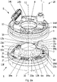
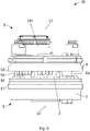
- FIG. 2a shows the changing device 26, which has an interchangeable coupling 1 and an interchangeable adapter 5.
- the interchangeable coupling 1 has a base body 2 and a tensioning element 3 for tensioning with a corresponding tensioning element 4 on the interchangeable adapter 5 .
- the clamping elements 3 and 4 interact in a known manner, so that only the components essential to the invention are explained below.
- the clamping element 3 on the interchangeable coupling 1 has a clamping cylinder with clamping balls, which can be clamped with corresponding clamping receptacles of the clamping element 4 on the interchangeable adapter 5 .
- the interchangeable coupling 1 has, for example, four electrical plug-in connection elements 6a, 6b, 6c and 6d, an optical plug-in connection element 7 and two fluid coupling elements 8a, 8b.
- the fluid coupling elements 8a, 8b are plugged into one another, with a fluid-conducting connection between fluid lines is established within the fluid coupling elements 8a, 8b.
- the fluid coupling elements 8a, 8b each protrude further in the axial connection direction with the interchangeable adapter 5 than the electrical plug-in connection elements 6a, 6b, 6c and 6d, as a result of which the fluid coupling elements 8a, 8b - as will be explained in detail below - Bring about an alignment of the electrical plug-in connection elements 6a, 6b, 6c and 6d when the interchangeable adapter 5 is connected.
- the interchangeable adapter 5 has a base body 9 .
- the base body 2 of the interchangeable coupling 1 and the base body 9 of the interchangeable adapter 5 each have a cylindrical basic shape.
- the longitudinal axis 10 of the base body 2 and the longitudinal axis 11 of the base body 9 are congruent.
- the clamping elements 3 and 4 prevent the interchangeable adapter 5 from shifting in relation to the interchangeable coupling 1 in the axial and radial directions of the axes of rotation 10 and 11, whereas the clamping elements 3 and 4 do not prevent the interchangeable adapter 5 from rotating about the longitudinal axis 10.
- the interchangeable coupling 1 in the embodiment shown has an anti-rotation element for connection to a corresponding anti-rotation element on the interchangeable adapter.
- two connecting pins 12a and 12b tapered in the direction of the connection to the interchangeable adapter 5 are provided as an anti-rotation element on the interchangeable coupling 1
- two matching pin receptacles 13a and 13b are provided as a corresponding anti-rotation element on the interchangeable adapter 5.
- the fluid coupling elements 8a and 8b extend parallel to the two tapered connecting pins 12a and 12b. Due to the tapering of the connecting pins 12a and 12b, the electrical connector elements 6a, 6b, 6c and 6d and the optical connector element 7 before connecting the interchangeable coupling 1 with the Interchangeable adapter 5 on four corresponding electrical connector elements 14a, 14b, 14c and 14d and a corresponding optical connector element 15 on interchangeable adapter 5 first roughly aligned by fluid coupling elements 8a and 8b and then finely aligned by connecting pins 12a and 12b. Furthermore, the fluid coupling elements 8a and 8b have a greater radial distance from the central axis of the tensioning element 3 than the connecting pins 12a and 12b. As a result, when rotating the interchangeable adapter 5 relative to the interchangeable coupling 1, the fluid coupling elements 8a and 8b can absorb torques better than the connecting pins 12a and 12b, which can be dimensioned smaller as a result.
- the interchangeable coupling 1 has a sealing ring 16 for the sealing connection of the interchangeable coupling 1 to the interchangeable adapter 5 .
- the sealing ring 16 has a V-shaped cross section. The tip of the "V" points inwards in order to allow a liquid from the environment to collect and then drip off at the sealing ring 16 .
- the sealing ring 16 extends in the circumferential direction on the (relative to the longitudinal axis of the interchangeable coupling 1) outer edge 17 of the base body 2 of the interchangeable coupling 1 on the side of the interchangeable adapter 5.
- An outer edge of the sealing ring 16 is in contact with the interchangeable adapter 5 in the direction of an outer edge 18 of the interchangeable adapter 5 is pressed and thus dissipates any moisture present in the direction of the outer edge 18 of the interchangeable adapter 5 .
- the base body 2 of the interchangeable coupling 1 has recesses 19a, 19b, 19c, 19d, 19e, 19f and 19g in the base body 2 for the detachable arrangement of the elements mentioned.
- the electrical plug-in connection element 6a has high-voltage and high-current contacts which are connected to the high-voltage and high-current contacts of the corresponding electrical plug-in connection element 14a of the interchangeable adapter 5 when the interchangeable coupling 1 is clamped to the interchangeable adapter 5 .
- the high-voltage and high-current contacts are used, for example, to drive servo motors at 680 V DC link voltage on a motorized changeover adapter.
- the electrical plug-in connection element 6b has high-frequency contacts, which are connected to the high-frequency contacts of the corresponding electrical plug-in connection element 14b of the interchangeable adapter 5 when the interchangeable coupling 1 is clamped to the interchangeable adapter 5 .
- the high-frequency contacts which are designed as coaxial high-frequency contacts in the embodiment shown, are used, for example, in non-destructive testing of a component using ultrasound.
- a tool mounted on the changeover adapter 5 is supplied with high-frequency pulses via the high-frequency contacts in order to generate ultrasonic waves.
- further high-frequency contacts are present on the electrical plug-in connection element 6c, which are connected to the high-frequency contacts of the corresponding electrical plug-in connection element 14c of the interchangeable adapter 5 when the interchangeable coupling 1 is clamped to the interchangeable adapter 5 .
- the high-frequency contacts of the electrical plug-in connection element 6c which in the embodiment shown are designed as high-frequency contacts with a high packing density, are used, for example, to test a component non-destructively using ultrasound with sound beam alignment.
- high-frequency pulses that are time-delayed from contact to contact are made available to a tool, which is equipped with an ultrasonic group radiator and is mounted on the interchangeable adapter 5, via the high-frequency contacts of the corresponding electrical plug-in connection elements 6c and 14c.
- the high-frequency contacts with a high packing density are spring-loaded to provide additional protection against damage caused by impact, for example.
- the electrical plug-in connection element 6d is a multi-pole travel sensor interface, which is connected to the corresponding electrical plug-in connection element 14d of the interchangeable adapter 5, which is also designed as a multi-pole travel sensor interface, in the clamped state of the interchangeable coupling 1 with the interchangeable adapter 5.
- signals are exchanged between the tool that is mounted on the interchangeable adapter 5 and a control element that is connected to the interchangeable coupling 1 .
- the electrical plug-in connection element 6b has, in addition to the high-frequency contacts, contacts for the transmission of supply voltages and contacts for data transmission, the contacts on the interchangeable coupling 1 in the clamped state of the interchangeable coupling 1 with the interchangeable adapter 5 having corresponding contacts of the corresponding electrical plug-in connection element 14b of the interchangeable adapter 5 are connected.
- the contacts for transmitting supply voltages are used, for example, to connect electrical lines leading to a tool on the interchangeable adapter 5 for non-destructive testing of a component with electrical lines leading to a voltage source.
- the electrical plug connection element 6b in the embodiment shown has contacts for data transmission of tool identification ("ToolID”) and analog and digital sensor information.
- ToolID which is a unique identification of a tool that is mounted on the change adapter 5, and analog and digital information of a sensor attached to the tool via the contacts
- Data transmission of the electrical connector element 6b for example, forwarded to a data processing device that is connected to the interchangeable coupling 1.
- the optical plug-in connection element 7 has optical waveguides, which are connected to the optical waveguides of the corresponding optical plug-in connection element 15 of the interchangeable adapter 5 when the interchangeable coupling 1 is clamped to the interchangeable adapter 5 .
- the optical fibers are used, for example, in the non-destructive testing of a component using thermography or digital radiography.
- the optical fibers serve as an interference-free transmission channel with a very high bandwidth.
- the interchangeable coupling 1 in the embodiment shown has a center piece 20 on the side facing the handling element.
- the center piece 20 has connecting elements 21a, 21b, 21c, 21d, 21e, 21f, 21g, 21h, 21i and 21j.
- the center piece has a basic cylindrical shape, with the longitudinal axis 22 of the center piece 20 and the axis of rotation 10 of the base body 2 being congruent.
- connection element 21j is used for the sealed feed-through of high-frequency individual contact cables and for the sealed feed-through of a micro-coaxial cable to supply the high-frequency contacts with a high packing density of the electrical plug-in connection element 6c, which are soldered onto a rectangular circuit board and connected to the micro-coaxial cable via this.
- the rectangular circuit board and the micro coaxial cable are delivered ready-made and must therefore be installed together and be interchangeable. Sealing from an environment is accomplished by squeezing a sealing block through the terminal member 21j, through which sealing block the high-frequency single-contact cables and the micro-coaxial cable are passed. The pinch seals off the cables on the one hand and seals off the housing on the other.
- the middle piece 20 is shaped in such a way that the middle piece 20 can additionally be filled with a sealing compound in an inner cavity.
- the connection elements 21a to 21j are in arranged in the radial direction of the axis of rotation 22 to the outside on the central piece 20 in order to allow a sealed connection of lines in the radial direction on the interchangeable coupling 1, the lines being relieved of stresses caused by tensile forces.
- This design is provided when the handling element is designed as a robot arm that can be moved on several axes, in order to enable the cables to be routed away.
- the center piece 20 can be omitted.
- the base body 2 of the interchangeable coupling 1 has pneumatic transmission channels 23a, 23b, 23c and 23d and the center piece 20 of the interchangeable coupling 1 has pneumatic transmission channels 24a, 24b, 24c and 24d.
- the adapter plate 25 is bolted to a machine flange, which is not shown in the embodiment shown.
- the machine flange is state-of-the-art, so that no further explanations are required.
- the screw connection of the interchangeable coupling 1 with the center piece 20, the adapter plate 25 and the machine flange is arranged in such a way that the machine flange is screwed and assembled starting.
- the adapter plate 25 is screwed on first, then the center piece 20 and then the interchangeable coupling 1.
- the adapter 25, the center piece 20, the interchangeable coupling 1 and also the screw connections are designed in such a way that they seal off from the outside and therefore no moisture can enter from the outside. Sealing off from the environment also applies to various interchangeable adapters.
- the changing device 26 shows the interchangeable coupling 1 and the interchangeable adapter 5 being detachably connected to one another.
- the interchangeable coupling 1 is clamped to the interchangeable adapter 5 by clamping the clamping element 3 of the interchangeable coupling 1 to the clamping element 4 of the interchangeable adapter 5 .
- the changing adapter 5 of the changing device 26 enables the assembly of different tools for the non-destructive testing of a fiber-plastic composite component.
- the fluid coupling elements 8a and 8b protrude further in the direction of the interchangeable adapter 5 and thus prevent the corresponding electrical or optical plug-in connection elements from being placed in a twisted state on the electrical or optical plug-in connection elements of the interchangeable coupling 1.
- FIGS. 9 and 10 show the interchangeable coupling 1 and the interchangeable adapter 5 of the interchangeable device 26 during the connection process before the clamped state is reached.
- the interchangeable coupling 1 and the interchangeable adapter 5 are aligned with one another by the connection of the fluid coupling elements 8a and 8b of the interchangeable coupling 1 with the corresponding fluid elements 29a and 29b of the interchangeable adapter 5 .
- FIG. 11 shows the changing adapter 5 of the changing device 26 according to FIG Figure 2a , on which a tool 30 for non-destructive testing of a fiber-plastic composite component is mounted.
- the tool 30 has a cylindrical motor housing 31 which is coaxially adjacent to the interchangeable adapter 5 and is connected to the interchangeable adapter 5 in a rotationally fixed and detachable manner.
- a servomotor is arranged in the motor housing 31, which 11 is not shown.
- the tool 30 On one side of the motor housing 31 which is opposite the interchangeable adapter 5 when the tool 30 is in the installed state, the tool 30 has a cylindrical gear housing 32 which is arranged coaxially with the cylindrical motor housing 31 .
- a gear is arranged in the gear housing 32, which gear is connected to the servomotor and converts torques and/or speeds generated by the servomotor.
- the tool 30 has a mechanical collision protection 33 between the motor housing 31 and the gear housing 32 , which allows the gear housing 32 to be folded away from the motor housing 31 in the event of mechanical external influences on the gear housing 32 .
- a tool head 35 is arranged on a side 34 of the gear housing 32 opposite the motor housing 31 and is rotatably arranged on a holder 36 fastened to the gear housing 32 .
- the tool head 35 can be rotated relative to the holder 36 and thus relative to the changing device 26 with the aid of the servo motor.
- Of the Tool head 35 has a test head 37 and a water nozzle 38 .
- a protective plate 39 is fastened to the side 34 opposite the motor housing 31 and is arranged on a side of the tool head 35 which is opposite the holder 36 .
- the tool 30 has an electrical plug-in connection element with four high-voltage and high-current contacts for driving the servo motor on a side in contact with the interchangeable adapter 5, which connects to the high-voltage and high-current contacts of the corresponding electrical plug-in connection element 14a of the interchangeable adapter 5 when the tool 30 is in the assembled state with the interchangeable adapter 5 are connected.
- the tool 30 has an electrical plug-in connection element with two contacts for a motor brake of the servomotor on the side in contact with the interchangeable adapter 5, which is connected to a corresponding plug-in connection element of the interchangeable adapter 5 when the tool 30 is in the installed state.
- an electrical plug-in connection element with a shielded 14-pin encoder interface for an external measuring system, a 9-pin encoder interface for a motor measuring system of the servo motor and six data lines for a ToolID, with the electrical plug-in connection element having can be connected to the corresponding electrical plug-in connection element 14b of the changeover adapter 5 in order to clearly identify the mounted tool 30 and to forward data measured by the external measuring system and by the motor measuring system.
- the tool 30 has two fluid valves on the side in contact with the interchangeable adapter 5, which are connected to the fluid elements 29a and 29b of the interchangeable adapter 5 when the tool 30 is in the assembled state. Liquid lines lead from the two liquid valves to the water nozzle 38 in order to supply it with water. Furthermore, the tool 30 has three on the interchangeable adapter 5 side Coupling elements for air, which are each connected to a corresponding coupling element for air on the exchange adapter 5. A first air coupling element of the tool 30 supplies the tool 30 with sealing air in order to seal it off from the environment. A second coupling element for air serves to monitor mechanical collision protection 33 by supplying sealing air to mechanical collision protection 33 .
- tool 30 has an electrical plug-in connection element with two coaxial high-frequency contacts on the side in contact with interchangeable adapter 5, which are connected to high-frequency contacts of the corresponding electrical plug-in connection element 14c of interchangeable adapter 5 when tool 30 is in the installed state with interchangeable adapter 5.
- the test head 37 is supplied with high-frequency pulses via the two coaxial high-frequency contacts of the tool 30 in order to generate ultrasonic waves.
Landscapes
- Engineering & Computer Science (AREA)
- Robotics (AREA)
- Mechanical Engineering (AREA)
- Physics & Mathematics (AREA)
- Optics & Photonics (AREA)
- Connector Housings Or Holding Contact Members (AREA)
- Vehicle Body Suspensions (AREA)
- Eye Examination Apparatus (AREA)
- Seal Device For Vehicle (AREA)
- Massaging Devices (AREA)
- Optical Modulation, Optical Deflection, Nonlinear Optics, Optical Demodulation, Optical Logic Elements (AREA)
- Mechanical Coupling Of Light Guides (AREA)
Description
- Die Erfindung betrifft eine Wechselvorrichtung insbesondere zum nichtzerstörenden Prüfen eines Bauteils, vorzugsweise eines Faser-Kunststoff-Verbund-Bauteils, aufweisend:
eine Wechselkupplung zur Verbindung eines Handhabungselements, insbesondere eines Roboterarms, mit einem Wechseladapter, und - den Wechseladapter, der mit der Wechselkupplung lösbar verbunden ist, wobei die Wechsekupplung aufweist_
- ein Spannelement zum Verspannen mit einem korrespondierenden Spannelement am Wechseladapter,
- zumindest ein elektrisches, und/oder optisches Steckverbindungselement zur Verbindung mit zumindest einem korrespondierenden elektrischen und/oder optischen Steckverbindungselement am Wechseladapter.
- Weiters betrifft die Erfindung eine Prüf- bzw. Bearbeitungsanlage mit einer solchen Wechselvorrichtung.
- Bei derartigen Wechselvorrichtungen werden üblicherweise verschiedene Anschlüsse zur Verbindung mit korrespondierenden Anschlüssen am Wechseladapter benötigt, wie z.B. Steckverbindungen mit Hochspannungs- und/oder Hochstromkontakten, Hochfrequenzkontakten, hochpolige (160 Pins) Miniatur-Steckverbindungen und/oder Steckverbindungen für Lichtwellenleiter.
- Aus der
EP 1 590 134 ist eine Wechselkupplung bekannt, welche mit einem Wechseladapter verriegelt werden kann. Im verriegelten Zustand sind einander zugeordnete Medien- und Kommunikationsleitungen von Wechselkupplung und Wechseladapter, beispielsweise für Druckluft, Sensorsignale, Schweißstrom oder Kühlmittel, miteinander verbunden. Nachteilig ist jedoch, dass die elektrischen bzw. optischen Steckverbindungselemente beim Verbinden von Wechselkupplung und Wechseladapter präzise aneinander ausgerichtet werden müssen, um eine Beschädigung der empfindlichen elektrischen bzw. optischen Steckverbindungselemente zu verhindern. -
WO 2015/074710 zeigt eine andersartige Ablagestation, in der eine werkzeugseitige Aufnahmeplatte und eine roboterseitige Aufnahmeplatte abgelegt werden können. -
DE 11 2015 003 807 T5 beschreibt eine Mastereinheit zur Befestigung an einem Roboterarm und eine Werkzeugeinheit zur Befestigung an einem Roboterwerkzeug. -
US 2016/059424 A1 offenbart ein Masterelement und ein Werkzeugelement. - Die
US 2009/143207 A1 zeigt eine rekonfigurierbare Vorrichtung mit numerischer Steuerung für die Herstellung von Flugzeugbauteilen. Abnehmbare Komponenten bzw. Werkzeuge können mittels einer Steckverbindung verbunden werden. Es ist eine Kupplung vorgesehen, die Klemmen, Rohre und Drähte zur Verbindung aufweist. Aus derJP H06 39763 - Ein weiterer Werkzeugwechsler ist aus der
US 5 782 571 A bekannt. - Die Aufgabe der vorliegenden Erfindung besteht darin, zumindest einzelne Nachteile des Standes der Technik zu lindern bzw. zu beseitigen. Die Erfindung setzt sich insbesondere zum Ziel, die elektrischen bzw. optischen Steckverbindungselemente beim Anschließen des Wechseladapters zu schonen.
- Diese Aufgabe wird durch eine Wechselvorrichtung mit den Merkmalen von Anspruch 1 und eine Prüf- bzw. Bearbeitungsanlage mit den Merkmalen von Anspruch 14 gelöst. Bevorzugte Ausführungsformen sind in den abhängigen Ansprüchen angegeben.
- Die Erfindung sieht daher zwei Wasserkupplungselemente zur Verbindung mit zwei entsprechenden Wasserkupplungselementen am Wechseladapter vor, wobei die Wasserkupplungselemente weiter in Richtung der Verbindung mit dem Wechseladapter (d.h. in Längsrichtung bzw. axialer Richtung der Wechselkupplung) vorstehen als das elektrische und/oder optische Steckverbindungselement, so dass das elektrische und/oder optische Steckverbindungselement und das korrespondierende elektrische und/oder optische Steckverbindungselement am Wechseladapter vor ihrem Aufeinandertreffen durch das Verbinden der Wasserkupplungselemente mit den entsprechenden Wasserkupplungselementen am Wechseladapter aneinander ausgerichtet sind.
- Somit werden die zwei Wasserkupplungselemente der Wechselkupplung beim Anschließen des Wechseladapters an die Wechselkupplung mit den korrespondierenden Wasserkupplungselementen am Wechseladapter verbunden, bevor die elektrischen bzw. optischen Steckverbindungselemente mit den korrespondierenden elektrischen bzw. optischen Steckverbindungselementen am Wechseladapter in Eingriff gebracht werden. Dadurch werden die korrespondierenden elektrischen bzw. optischen Steckverbindungselemente vor dem Ankuppeln des Wechseladapters an die Wechselkupplung aneinander ausgerichtet, d.h. in der bestimmungsgemäßen Drehlage bezüglich der Längsachse der Wechselkupplung zueinander angeordnet. Diese Ausführung bringt den Vorteil mit sich, dass eine Beschädigung der empfindlichen elektrischen bzw. optischen Steckverbindungselemente zuverlässig vermieden werden kann. Dies funktioniert sowohl bei einem manuellen, als auch bei einem automatisierten Wechselvorgang. Das Ankuppeln des Wechseladapters an die Wechselkupplung wird bei einem manuellen Wechselvorgang von einer Person und bei einem automatisierten Wechselvorgang automatisch von einem Roboter durchgeführt. Weiters ergibt sich der Vorteil, dass das Eindringen von Flüssigkeiten und Gasen aus einer Prüf- bzw. Bearbeitungsumgebung der Wechselkupplung in die Wasserkupplungselemente aufgrund der selbstdichtenden Funktion der weiter in Richtung der Verbindung mit dem Wechseladapter vorstehenden Wasserkupplungselemente erschwert wird. Dadurch wird eine Verunreinigung der Flüssigkeit, insbesondere des Wassers, in den Wasserkupplungselementen und den zugehörigen Flüssigkeitsleitungen, insbesondere Wasserleitungen, der Wechselkupplung und des Wechseladapters, erschwert oder verhindert.
- Gemäß einer bevorzugten Ausführungsform weist ein Wechselvorgang die folgenden Schritte auf:
- Abnehmen eines benutzten Wechseladapters von der Wechselkupplung;
- Abtupfen und/oder Absaugen der Wasserkupplungselemente der Wechselkupplung und der Wasserkupplungselemente eines anzubringenden Wechseladapters zur Verhinderung eines Flüssigkeitseintrags in den Wechseladapter und/oder in die Wechselkupplung;
- Ausrichten der Wasserkupplungselemente der Wechselkupplung mit den korrespondierenden Wasserkupplungselementen am anzubringenden Wechseladapter;
- Verbinden der Wasserkupplungselemente der Wechselkupplung mit den korrespondierenden Wasserkupplungselementen am anzubringenden Wechseladapter; und
- In Eingriff bringen der elektrischen bzw. optischen Steckverbindungselemente mit den korrespondierenden elektrischen bzw. optischen Steckverbindungselementen am anzubringenden Wechseladapter.
- Ein Flüssigkeitseintrag beim Kuppeln bzw. Abkuppeln wird durch die Wasserkupplungselemente zuverlässig vermieden. Eine Kontamination der elektrischen bzw. optischen Steckverbindungselemente durch fallweise auftretende Tropfenbildung an den Kontaktflächen der Wasserkupplungselemente wird durch die Vorlagerung bzw. Versenkung der Kontaktflächen der Wasserkupplungselemente der Wechselkupplung bzw. des Wechseladapters verhindert.
- Die Wechselkupplung weist bevorzugt einen Grundkörper auf, welcher auf der dem Wechseladapter zugewandten Stirnseite eine vorzugsweise im Wesentlichen senkrecht zur Längsachse der Wechselkupplung erstreckte Hauptverbindungsfläche aufweist, die im verbundenen Zustand an einer korrespondierenden Hauptverbindungsfläche des Wechseladapters anliegt. Die elektrischen und/oder optischen Steckverbindungselemente stehen im Vergleich zu den Wasserkupplungselementen weniger weit in Richtung der Längsachse der Wechselkupplung vor, so dass die korrespondierenden elektrischen und/oder optischen Steckverbindungselemente in der bestimmungsgemäßen Orientierung zueinander ausgerichtet sind, wenn die korrespondierenden Hauptverbindungsflächen von Wechselkupplung und Wechseladapter miteinander in Kontakt kommen.
- Für die Zwecke dieser Offenbarung beziehen sich die Orts- und Richtungsangaben auf die Längsachse der Wechselkupplung, welche mit der Richtung des bestimmungsgemäßen Verbindens von Wechselkupplung und Wechseladapter zusammenfällt. Dabei bezieht sich "axial" auf die Richtung der Längsachse und "radial" auf die Richtung normal zur Längsachse der Wechselkupplung.
- Gemäß einer bevorzugten Ausführungsform weist die Wechselkupplung ein Drehsicherungselement zur Verbindung mit einem korrespondierenden Drehsicherungselement am Wechseladapter auf, wobei als Drehsicherungselement bevorzugt ein in Richtung der Verbindung mit dem Wechseladapter verjüngter Verbindungszapfen und als korrespondierendes Drehsicherungselement am Wechseladapter eine Zapfenaufnahme vorgesehen ist. Vorteilhafterweise kann das Drehsicherungselement aufgrund der ebenfalls eine Drehsicherung bewirkenden Verbindung zwischen den korrespondierenden Wasserkupplungselementen kleiner dimensioniert werden als bei Wechselkupplungen mit Flüssigkeitskupplungselementen ohne Drehmomentaufnahme. Ein weiterer Vorteil der Drehsicherungselemente ist es, dass so die Wechselkupplung noch genauer mit dem Wechseladapter ausgerichtet werden kann.
- Besonders bevorzugt ist es, wenn die Wasserkupplungselemente der Wechselkupplung der Wechselvorrichtung einen größeren radialen Abstand zum Spannelement aufweisen als das Drehsicherungselement. Durch diese Anordnung nehmen die Wasserkupplungselemente bei Verdrehung des Wechseladapters gegenüber der Wechselkupplung ein größeres Drehmoment auf als das Drehsicherungselement, wodurch eine kleinere Dimensionierung des Drehsicherungselements ermöglicht wird.
- Um das zumindest eine elektrische und/oder optische Steckverbindungselement und die Wasserkupplungselemente vor äußeren Einflüssen zu schützen, ist es günstig, wenn die Wechselkupplung einen Dichtungsring zur dichtenden Verbindung mit dem Wechseladapter aufweist, wobei der Dichtungsring bevorzugt einen V-förmigen Querschnitt aufweist. Aufgrund des V-förmigen Querschnitts kann Flüssigkeit der Umgebung, die sich an der Außenseite der Wechselkupplung ansammelt, abtropfen, so dass das elektrische und/oder optische Steckverbindungselement und die Wasserkupplungselemente vor der an der Außenseite der Wechselkupplung angesammelten Flüssigkeit geschützt sind.
- Gemäß einer bevorzugten Ausführungsform ist der Dichtungsring an einem (umfangseitigen) Außenrand eines vorzugsweise zylindrischen Grundkörpers der Wechselkupplung angeordnet.
- Gemäß einer bevorzugten Ausführungsform sind das elektrische und/oder optische Steckverbindungselement und die Wasserkupplungselemente jeweils in radialer Richtung gesehen innerhalb des Dichtungsrings angeordnet. Im verbundenen Zustand erstreckt sich der Dichtungsring an den aufeinandertreffenden Stirnseiten von Wechselkupplung und Wechseladapter, wobei die korrespondierenden elektrischen und/oder optischen Steckerverbindungselemente sowie die Flüssigkeitsverbindung innerhalb des Dichtungsrings geschützt angeordnet sind.
- Besonders bevorzugt weist der Grundkörper zumindest eine erste Aussparung zur lösbaren Anordnung des elektrischen und/oder optischen Steckverbindungselements und/oder zumindest eine zweite Aussparung zur lösbaren Anordnung des Flüssigkeitskupplungselements auf. In Gebrauch sind das elektrische und/oder optische Steckverbindungselement innerhalb der ersten Aussparung bzw. das Flüssigkeitskupplungselement innerhalb der zweiten Aussparung angeordnet und jeweils mit der zugehörigen Leitung vom Handhabungselement verbunden.
- Gemäß einer bevorzugten Ausführungsform weist die Wechselkupplung ein Kupplungselement für Luft, insbesondere Druckluft, zur Verbindung mit einem entsprechenden Kupplungselement für Luft, insbesondere Druckluft, am Wechseladapter, auf. Die Druckluft kann von einem am Wechseladapter montierten Werkzeug zu dessen zweckmäßigem Einsatz verwendet werden. Die Druckluft wird im Einsatz insbesondere für eines von pneumatischer Hubzylinder, Abblasvorrichtung, Sperrluft oder pneumatischer Kollisionsschutz genutzt.
- Gemäß einer bevorzugten Ausführungsform ist das zumindest eine elektrische Steckverbindungselement elektrisch isoliert von der Wechselkupplung. Besonders bevorzugt ist das zumindest eine elektrische Steckverbindungselement einzeln geerdet. Dies wirkt sich insbesondere auf die elektromagnetische Verträglichkeit benachbarter elektrischer Komponenten aus. Dies ist speziell bei Hochfrequenzanwendungen von Bedeutung.
- Um eine Tragkraft der Wechselkupplung zu reduzieren, ist es günstig, wenn das zumindest eine elektrische Steckverbindungselement radial gefedert ist. Die Tragkraft der Wechselkupplung bleibt somit unabhängig von der Art und der Anzahl der elektrischen Steckverbindungselemente.
- Gemäß einer bevorzugten Ausführungsform weist zumindest ein elektrisches Steckverbindungselement der Wechselkupplung Hochspannungs- bzw. Hochstromkontakte auf. In diesem Zusammenhang bedeutet Hochspannung eine elektrische Spannung mit mindestens 680 Volt Gleichstrom und Hochstrom eine elektrische Stromstärke von mindestens 25 Ampere.
- Weiters ist es günstig, wenn zumindest ein elektrisches Steckverbindungselement der Wechselkupplung Hochfrequenzkontakte aufweist. Hochfrequenz bedeutet in diesem Zusammenhang eine Frequenz ab 100 kHz bis 9 GHz. Die Hochfrequenzkontakte werden beispielsweise bei einem am Wechseladapter montierten Werkzeug zum zerstörungsfreien Prüfen eines Bauteils mittels Ultraschall, insbesondere Ultraschall mit Schallbündelausrichtung, verwendet. Die Schallbündelausrichtung ist eine gerichtete Abstrahlung von Ultraschallimpulsen einer am Werkzeug montierten Sonde.
- Gemäß einer bevorzugten Ausführungsform ist zumindest ein elektrisches Steckverbindungselement der Wechselkupplung hochpolig, wobei hochpolig eine Anzahl von mindestens 160 Polen bedeutet. Hochpolige Steckverbindungselemente werden beispielsweise bei Leitungen für Gruppenstrahl-Prüfköpfe zum Prüfen mit Phased-Array-Ultraschall zur Signalübertragung verwendet. Somit können Signale eines Werkzeugs, das am Wechseladapter montiert ist, über Leitungen und über das elektrische Steckverbindungselement zu einem Auswertegerät einer Phased-Array-Prüfelektronik übertragen werden.
- Gemäß einer bevorzugten Ausführungsform weist zumindest ein elektrisches Steckverbindungselement der Wechselkupplung Kontakte zur Übertragung einer Versorgungsspannung vom Handhabungselement an den Wechseladapter auf. Die Kontakte zur Übertragung der Versorgungsspannung werden beispielsweise beim nichtzerstörenden Prüfen eines Bauteils mithilfe eines am Wechseladapter montierten Werkzeugs, das von einer Spannungsquelle versorgt wird, verwendet, um elektrische Leitungen des Handhabungselements und des Werkzeugs über die Wechselkupplung und den Wechseladapter zu verbinden.
- Gemäß einer bevorzugten Ausführungsform weist zumindest ein elektrisches Steckverbindungselement der Wechselkupplung Kontakte zur Datenübertragung, insbesondere zur Übertragung einer Werkzeugidentifikation ("ToolID") und/oder analoger und/oder digitaler Sensordaten, vom Wechseladapter an das Handhabungselement, auf. Hierbei ist ToolID die eindeutige Identifikation eines Werkzeugs, beispielsweise mittels einer eindeutigen Nummer, und analoge und/oder digitale Sensorinformationen sind Informationen eines analogen und/oder digitalen Sensors eines am Wechseladapter montierten Werkzeugs.
- Gemäß einer bevorzugten Ausführungsform weist zumindest ein elektrisches Steckverbindungselement der Wechselkupplung Kontakte zur Übertragung von Massepunkten auf. Dadurch können, wenn unterschiedliche galvanisch getrennte Erdungspunkte notwendig sind, hochfrequente Einflüsse minimiert oder eliminiert werden.
- Bevorzugt weist zumindest ein optisches Steckverbindungselement der Wechselkupplung einen Lichtwellenleiter auf. Lichtwellenleiter dienen der Übertragung von Licht. Der Lichtwellenleiter des optischen Steckverbindungselements wird für verlustlose Übertragungen (Streamen) von digitalen Sensordaten mit einer hohen Bandbreite über lange Übertragungsstrecken verwendet. Insbesondere wird der Lichtwellenleiter des optischen Steckverbindungselements bei einem nichtzerstörenden Prüfen eines Bauteils mithilfe von Thermografie oder mithilfe eines digitalen Röntgen-Flächendetektors verwendet, wobei in beiden Fällen Sensordaten des verwendeten Prüfkopfes mit hoher Bandbreite zu einer Auswertestation gestreamt werden.
- Bevorzugt weist die Wechselkupplung ein Mittelstück an der dem Handhabungselement zugewandten Seite mit einem Anschlusselement zum Anschluss einer Leitung vom Handhabungselement auf. Besonders bevorzugt steht das Anschlusselement in radialer Richtung von dem Mittelstück nach außen ab. Dadurch ermöglicht das Mittelstück einen Anschluss einer Leitung an die Wechselkupplung in radialer Richtung. Dies wird beispielsweise bei bestimmten Handhabungselementen benötigt, um die Wegführung der Leitung zu ermöglichen, ohne die Beweglichkeit des Handhabungselements zu beeinträchtigen.
- Gemäß einer bevorzugten Ausführungsform weist die Wechselkupplung, vorzugsweise zumindest der Grundkörper, insbesondere der Grundkörper und das Mittelstück, Durchgangsbohrungen zum Verbinden der Wechselkupplung an der dem Handhabungselement zugewandten Seite mit einer Adapterplatte auf, um die Verbindung der Wechselkupplung mit einem normierten Handhabungselement zu vereinfachen.
- Gemäß einer bevorzugten Ausführungsform ist eine Zuführung von Kabeln zu der Wechselkupplung in Richtung der Längsachse der Wechselkupplung angeordnet. Alternativ kann die Zuführung von Kabeln zu der Wechselkupplung orthogonal zur Längsachse der Wechselkupplung angeordnet sein.
- Gemäß einer bevorzugten Ausführungsform weist eine Prüf- bzw. Bearbeitungsanlage, insbesondere zum nichtzerstörenden Prüfen eines Bauteils, vorzugsweise eines Faser-Kunststoff-Verbund-Bauteils, beispielsweise eines Flugzeugbauteils, ein Handhabungselement, insbesondere einen Roboterarm, eine Wechselvorrichtung gemäß einer der oben beschriebenen Ausführungsformen auf ,wobei der Wechseladapter über die Wechselkupplung mit dem Handhabungselement lösbar verbunden ist.
- Die Erfindung wird nachstehend anhand eines in den Zeichnungen dargestellten, nicht einschränkenden Ausführungsbeispiels weiter erläutert.
-
Fig. 1 zeigt eine erfindungsgemäße Prüfanlage, die ein Handhabungselement und eine mehrteilige Wechselvorrichtung aufweist. -
Fig. 2a zeigt die Wechselvorrichtung gemäßFig. 1 , die eine Wechselkupplung und einen Wechseladapter aufweist, in einer Explosionsdarstellung. -
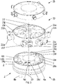
Fig. 2b zeigt die Wechselkupplung gemäßFig. 1 ,2 samt einem Mittelstück sowie eine Adapterplatte in einer Explosionsdarstellung. -
Fig. 3 zeigt die Wechselkupplung, das Mittelstück und die Adapterplatte gemäßFig. 2b in einer zweiten Explosionsdarstellung. -
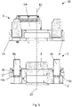
Fig. 4 zeigt die Wechselvorrichtung gemäßFig. 2a im entkoppelten Zustand in einer Seitenansicht. -
Fig. 5 zeigt einen Schnitt durch die Wechselvorrichtung im entkoppelten Zustand gemäßFig. 4 . -
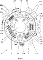
Fig. 6 zeigt die Wechselkupplung, das Mittelstück und die Adapterplatte gemäßFig. 2b in Aufsicht. -
Fig. 7 zeigt die Wechselvorrichtung gemäßFig. 2a im gekuppelten und verspannten Zustand in einer Seitenansicht. -
Fig. 8 zeigt einen Schnitt der Wechselvorrichtung im gekuppelten und verspannten Zustand gemäßFig. 7 . -
Fig. 9 zeigt die Wechselvorrichtung gemäßFig. 2a im ausgerichteten Zustand von Wechselkupplung und Wechseladapter in einer Seitenansicht. -
Fig. 10 zeigt einen Schnitt der Wechselvorrichtung gemäßFig. 9 . -
Fig. 11 zeigt den Wechseladapter gemäßFig. 2a und ein Werkzeug zum nichtzerstörenden Prüfen eines Faser-Kunststoff-Verbund-Bauteils. -
Fig. 1 zeigt eine erfindungsgemäße Prüfanlage 27 zum nichtzerstörenden Prüfen eines Faser-Kunststoff-Verbund-Bauteils. Die Prüfanlage weist eine Wechselvorrichtung 26, eine Adapterplatte 25 und ein Handhabungselement 28 auf, das als Roboterarm ausgeführt ist. Die Adapterplatte 25 ist an einer Seite an dem Handhabungselement 28 montiert und an der anderen Seite mit der Wechselvorrichtung 26 lösbar verbunden. -
Fig. 2a zeigt die Wechselvorrichtung 26, die eine Wechselkupplung 1 und einen Wechseladapter 5 aufweist. Die Wechselkupplung 1 weist einen Grundkörper 2 und ein Spannelement 3 zum Verspannen mit einem korrespondierenden Spannelement 4 an dem Wechseladapter 5 auf. Die Spannelemente 3 und 4 wirken in bekannter Weise zusammen, so dass im Folgenden lediglich die für die Erfindung wesentlichen Komponenten erläutert werden. In der gezeigten Ausführung weist das Spannelement 3 an der Wechselkupplung 1 einen Spannzylinder mit Spannkugeln auf, welche mit entsprechenden Spannaufnahmen des Spannelements 4 am Wechseladapter 5 verspannbar sind. - Wie aus
Fig. 2a ersichtlich, weist die Wechselkupplung 1 beispielsweise vier elektrische Steckverbindungselemente 6a, 6b, 6c und 6d, ein optisches Steckverbindungselement 7 und zwei Flüssigkeitskupplungselemente 8a, 8b auf. Beim Verbinden der Wechselkupplung 1 mit dem Wechseladapter 5 werden die Flüssigkeitskupplungselemente 8a, 8b ineinander gesteckt, wobei eine flüssigkeitsleitende Verbindung zwischen Flüssigkeitsleitungen innerhalb der Flüssigkeitskupplungselemente 8a, 8b hergestellt wird. - Wie aus der Zeichnung weiters ersichtlich, stehen die Flüssigkeitskupplungselemente 8a, 8b jeweils weiter in axialer Verbindungsrichtung mit dem Wechseladapter 5 vor als die elektrischen Steckverbindungselemente 6a, 6b, 6c und 6d, wodurch die Flüssigkeitskupplungselemente 8a, 8b - wie nachstehend noch im Detail erläutert werden wird - beim Anschließen des Wechseladapters 5 eine Ausrichtung der elektrischen Steckverbindungselemente 6a, 6b, 6c und 6d bewirken.
- Wie aus
Fig. 2a ,4 und5 ersichtlich, weist der Wechseladapter 5 einen Basiskörper 9 auf. Der Grundkörper 2 der Wechselkupplung 1 und der Basiskörper 9 des Wechseladapters 5 weisen jeweils eine zylindrische Grundform auf. Bei Verbindung der Wechselkupplung 1 mit dem Wechseladapter 5 mithilfe der Spannelemente 3 und 4 sind die Längsachse 10 des Grundkörpers 2 und die Längsachse 11 des Basiskörpers 9 deckungsgleich. Die Spannelemente 3 und 4 verhindern ein Verschieben des Wechseladapters 5 in Bezug auf die Wechselkupplung 1 in axialer und radialer Richtung der Rotationsachsen 10 und 11, wohingegen eine Verdrehung des Wechseladapters 5 um die Längsachse 10 durch die Spannelemente 3 und 4 nicht verhindert wird. Aus diesem Grund weist die Wechselkupplung 1 in der gezeigten Ausführung ein Drehsicherungselement zur Verbindung mit einem korrespondierenden Drehsicherungselement am Wechseladapter auf. Als Drehsicherungselement an der Wechselkupplung 1 sind in der gezeigten Ausführung zwei in Richtung der Verbindung mit dem Wechseladapter 5 verjüngte Verbindungszapfen 12a und 12b und als korrespondierendes Drehsicherungselement am Wechseladapter 5 zwei dazu passende Zapfenaufnahmen 13a und 13b vorgesehen. - In der gezeigten Ausführungsform erstrecken sich die Flüssigkeitskupplungselemente 8a und 8b parallel zu den beiden verjüngten Verbindungszapfen 12a und 12b. Aufgrund der Verjüngung der Verbindungszapfen 12a und 12b werden die elektrischen Steckverbindungselemente 6a, 6b, 6c und 6d und das optische Steckverbindungselement 7 vor dem Verbinden der Wechselkupplung 1 mit dem Wechseladapter 5 an vier entsprechenden elektrischen Steckverbindungselementen 14a, 14b, 14c und 14d und einem entsprechenden optischen Steckverbindungselement 15 am Wechseladapter 5 zunächst durch die Flüssigkeitskupplungselemente 8a und 8b grob ausgerichtet und danach durch die Verbindungszapfen 12a und 12b fein ausgerichtet. Weiters weisen die Flüssigkeitskupplungselemente 8a und 8b einen größeren radialen Abstand zur Mittelachse des Spannelements 3 auf als die Verbindungszapfen 12a und 12b. Dadurch können die Flüssigkeitskupplungselemente 8a und 8b beim Verdrehen des Wechseladapters 5 gegenüber der Wechselkupplung 1 Drehmomente besser aufnehmen als die Verbindungszapfen 12a und 12b, welche dadurch kleiner dimensioniert werden können.
- In der gezeigten Ausführungsform weist die Wechselkupplung 1 einen Dichtungsring 16 zur dichtenden Verbindung der Wechselkupplung 1 mit dem Wechseladapter 5 auf. Der Dichtungsring 16 weist in der gezeigten Ausführung einen V-förmigen Querschnitt auf. Dabei zeigt die Spitze des "V"s nach innen, um ein Ansammeln und in weiterer Folge ein Abtropfen einer Flüssigkeit aus der Umgebung am Dichtungsring 16 zu ermöglichen. Der Dichtungsring 16 erstreckt sich in Umfangsrichtung am (bezogen auf die Längsachse der Wechselkupplung 1) Außenrand 17 des Grundkörpers 2 der Wechselkupplung 1 auf Seite des Wechseladapters 5. Eine Außenkante des Dichtungsrings 16 wird beim Kuppeln ab Kontakt mit dem Wechseladapter 5 in Richtung eines Außenrands 18 des Wechseladapters 5 gedrückt und führt somit etwaig anliegende Feuchtigkeit in Richtung des Außenrands 18 des Wechseladapters 5 ab.
- Wie aus
Fig. 2a und6 ersichtlich, sind die elektrischen Steckverbindungselemente 6a, 6b, 6c und 6d, das optische Steckverbindungselement 7 und die Flüssigkeitskupplungselemente 8a und 8b der Wechselkupplung 1 ebenso wie die elektrischen Steckverbindungselemente 14a, 14b, 14c und 14d und das optische Steckverbindungselement 15 des Wechseladapters 5 innerhalb des Dichtungsrings 16 angeordnet. Dadurch sind die korrespondierenden elektrischen Steckverbindungselemente und Flüssigkeitskupplungselemente gegen ein Eindringen von Flüssigkeiten und Gase aus der Umgebung geschützt. - Um die elektrischen Steckverbindungselemente 6a, 6b, 6c und 6d, das optische Steckverbindungselement 7 und die Flüssigkeitskupplungselemente 8a und 8b an der Wechselkupplung 1 austauschbar zu befestigen, weist der Grundkörper 2 der Wechselkupplung 1 Aussparungen 19a, 19b, 19c, 19d, 19e, 19f und 19g im Grundkörper 2 zur lösbaren Anordnung der genannten Elemente auf.
- In der gezeigten Ausführungsform weist das elektrische Steckverbindungselement 6a Hochspannungs- und Hochstromkontakte auf, die mit Hochspannungs- und Hochstromkontakten des korrespondierenden elektrischen Steckverbindungselementes 14a des Wechseladapters 5 im verspannten Zustand der Wechselkupplung 1 mit dem Wechseladapter 5 verbunden sind. Die Hochspannungs- und Hochstromkontakte werden beispielsweise zum Antreiben von Servomotoren bei 680 V Zwischenkreisspannung an einem motorisierten Wechseladapter verwendet.
- In der gezeigten Ausführungsform weist das elektrische Steckverbindungselement 6b Hochfrequenzkontakte auf, die mit Hochfrequenzkontakten des korrespondierenden elektrischen Steckverbindungselementes 14b des Wechseladapters 5 im verspannten Zustand der Wechselkupplung 1 mit dem Wechseladapter 5 verbunden sind. Die Hochfrequenzkontakte, die in der gezeigten Ausführung als koaxiale Hochfrequenzkontakte ausgeführt sind, werden beispielsweise beim nichtzerstörenden Prüfen eines Bauteils mittels Ultraschalles verwendet. Dabei wird ein am Wechseladapter 5 montiertes Werkzeug über die Hochfrequenzkontakte mit Hochfrequenzimpulsen versorgt, um Ultraschallwellen zu erzeugen.
- Weitere Hochfrequenzkontakte sind in der gezeigten Ausführungsform beim elektrischen Steckverbindungselement 6c vorhanden, die mit Hochfrequenzkontakten des korrespondierenden elektrischen Steckverbindungselementes 14c des Wechseladapters 5 im verspannten Zustand der Wechselkupplung 1 mit dem Wechseladapter 5 verbunden sind. Die Hochfrequenzkontakte des elektrischen Steckverbindungselements 6c, die in der gezeigten Ausführung als Hochfrequenzkontakte mit einer hohen Packungsdichte ausgeführt sind, werden beispielsweise verwendet, um ein Bauteil mittels Ultraschalles mit Schallbündelausrichtung zerstörungsfrei zu prüfen.
- Dabei werden von Kontakt zu Kontakt zeitversetzte Hochfrequenzimpulse einem Werkzeug, das mit einem Ultraschall-Gruppenstrahler ausgestattet ist und am Wechseladapter 5 montiert ist, über die Hochfrequenzkontakte der korrespondierenden elektrischen Steckverbindungselemente 6c und 14c zur Verfügung gestellt. Die Hochfrequenzkontakte mit hoher Packungsdichte sind federnd gelagert, um zusätzlich gegen Beschädigungen, die beispielsweise durch Stöße hervorgerufen werden, geschützt zu sein.
- In der gezeigten Ausführungsform ist das elektrische Steckverbindungselement 6d eine hochpolige Weggeber-Schnittstelle, die mit dem korrespondierenden elektrischen Steckverbindungselement 14d des Wechseladapters 5, das ebenfalls als hochpolige Weggeber-Schnittstelle ausgeführt ist, im verspannten Zustand der Wechselkupplung 1 mit dem Wechseladapter 5 verbunden ist. Dadurch werden Signale zwischen dem Werkzeug, das am Wechseladapter 5 montiert ist, und einem Regelungselement, das mit der Wechselkupplung 1 verbunden ist, ausgetauscht.
- In der gezeigten Ausführungsform weist das elektrische Steckverbindungselement 6b neben den Hochfrequenzkontakten Kontakte zur Übertragung von Versorgungsspannungen und Kontakte zur Datenübertragung auf, wobei die Kontakte an der Wechselkupplung 1 im verspannten Zustand der Wechselkupplung 1 mit dem Wechseladapter 5 mit entsprechenden Kontakten des korrespondierenden elektrischen Steckverbindungselementes 14b des Wechseladapters 5 verbunden sind. Die Kontakte zur Übertragung von Versorgungsspannungen werden beispielsweise verwendet, um elektrische Leitungen, die zu einem Werkzeug am Wechseladapter 5 zum zerstörungsfreien Prüfen eines Bauteils mit elektrischen Leitungen zu verbinden, die zu einer Spannungsquelle führen.
- Weiters weist das elektrische Steckverbindungselement 6b in der gezeigten Ausführungsform Kontakte zur Datenübertragung von Werkzeugidentifikation ("ToolID") und analoger und digitaler Sensorinformation auf. Dabei werden die ToolID, die eine eindeutige Identifikation eines Werkzeugs, das am Wechseladapter 5 montiert ist, und analoge und digitale Informationen eines am Werkzeug befestigen Sensors über die Kontakte zur Datenübertragung des elektrischen Steckverbindungselements 6b beispielsweise an ein Datenverarbeitungsgerät, das mit der Wechselkupplung 1 verbunden ist, weitergeleitet.
- In der gezeigten Ausführungsform weist das optische Steckverbindungselement 7 Lichtwellenleiter auf, die mit Lichtwellenleitern des korrespondierenden optischen Steckverbindungselementes 15 des Wechseladapters 5 im verspannten Zustand der Wechselkupplung 1 mit dem Wechseladapter 5 verbunden sind. Die Lichtwellenleiter werden beispielsweise beim zerstörungsfreien Prüfen eines Bauteils mithilfe von Thermografie oder digitaler Radiographie verwendet. Die Lichtwellenleiter dienen dabei als störfreier Übertragungskanal mit sehr hoher Bandbreite.
- Wie in
Fig. 2b und3 ersichtlich, weist die Wechselkupplung 1 in der gezeigten Ausführung ein Mittelstück 20 an der dem Handhabungselement zugewandten Seite auf. Das Mittelstück 20 weist Anschlusselemente 21a, 21b, 21c, 21d, 21e, 21f, 21g, 21h, 21i, und 21j auf. In der gezeigten Ausführung weist das Mittelstück eine zylindrische Grundform auf, wobei die Längsachse 22 des Mittelstücks 20 und die Rotationsachse 10 des Grundkörpers 2 deckungsgleich sind. Das Anschlusselement 21j dient zur abgedichteten Durchführung von Hochfrequenz-Einzelkontaktkabeln sowie zur abgedichteten Durchführung eines Microkoaxialkabels zur Versorgung der Hochfrequenz-Kontakte mit hoher Packungsdichte des elektrischen Steckverbindungselements 6c, die auf einer rechteckigen Platine aufgelötet und über diese mit dem Microkoaxialkabel verbunden sind. Die rechteckige Platine und das Microkoaxialkabel werden fertig konfektioniert geliefert und müssen somit zusammen verbaut werden und tauschbar sein. Die Abdichtung gegenüber einer Umgebung erfolgt durch Quetschen eines Dichtungsblocks durch das Anschlusselement 21j, wobei durch den Dichtungsblock die Hochfrequenz-Einzelkontaktkabel und das Microkoaxialkabel durchgeführt werden. Durch die Quetschung erfolgt einerseits eine Abdichtung der Kabel, andererseits eine Abdichtung zum Gehäuse hin. Falls eine hochwertigere Abdichtung notwendig sein sollte, so ist das Mittelstück 20 so ausgeformt, dass das Mittelstück 20 zusätzlich in einem inneren Hohlraum mit einer Dichtmasse ausgegossen werden kann. Die Anschlusselemente 21a bis 21j sind in radialer Richtung der Rotationsachse 22 nach außen an dem Mittelstück 20 angeordnet, um einen abgedichteten Anschluss von Leitungen in radialer Richtung an der Wechselkupplung 1 zu ermöglichen, wobei die Leitungen von Beanspruchungen durch Zugkräfte entlastet werden. Diese Ausführung wird dann vorgesehen, wenn das Handhabungselement als mehrachsig beweglicher Roboterarm ausgeführt ist, um die Wegführung der Leitungen zu ermöglichen. Bei einer anderen Ausführung des Handhabungselements, beispielsweise bei einer sogenannten Linearkinematik, kann das Mittelstück 20 wegfallen. - In der gezeigten Ausführungsform weist der Grundkörper 2 der Wechselkupplung 1 Pneumatikübertragungskanäle 23a, 23b, 23c und 23d und das Mittelstück 20 der Wechselkupplung 1 Pneumatikübertragungskanäle 24a, 24b, 24c und 24d auf. Die Adapterplatte 25 ist an einem Maschinenflansch angeschraubt, der in der gezeigten Ausführung nicht dargestellt ist. Der Maschinenflansch ist Stand der Technik, so dass sich nähere Ausführungen dazu erübrigen. Die Verschraubung der Wechselkupplung 1 mit dem Mittelstück 20, der Adapterplatte 25 und dem Maschinenflansch ist derart angeordnet, dass vom Maschinenflansch beginnend verschraubt und zusammengebaut wird. D.h. in dem Fall, in dem der Maschinenflansch ein Roboterflansch ist, wird zuerst die Adapterplatte 25, dann das Mittelstück 20 und dann die Wechselkupplung 1 verschraubt. Der Adapter 25, das Mittelstück 20, die Wechselkupplung 1 und auch die Verschraubungen sind so ausgeführt, dass diese nach außen in die Umgebung abdichten und somit kein Feuchtigkeitseintrag von außen erfolgt. Das Abdichten gegenüber der Umgebung gilt ebenfalls für verschiedene Wechseladapter.
-
Fig. 7 zeigt die Wechselvorrichtung 26, wobei die Wechselkupplung 1 und der Wechseladapter 5 lösbar miteinander verbunden sind. Hierbei ist die Wechselkupplung 1 mit dem Wechseladapter 5 durch ein Verspannen des Spannelements 3 der Wechselkupplung 1 mit dem Spannelement 4 des Wechseladapters 5 verspannt. Der Wechseladapter 5 der Wechselvorrichtung 26 ermöglicht in der gezeigten Ausführungsform die Montage verschiedener Werkzeuge zum nichtzerstörenden Prüfen eines Faser-Kunststoff-Verbund-Bauteils. - Wie in
Fig. 8 ersichtlich, stehen die Flüssigkeitskupplungselemente 8a und 8b weiter in Richtung des Wechseladapters 5 vor und verhindern somit ein Aufsetzen der korrespondierenden elektrischen bzw. optischen Steckverbindungselemente in einem verdrehten Zustand auf die elektrischen bzw. optischen Steckverbindungselemente der Wechselkupplung 1. -
Fig. 9 und10 zeigen die Wechselkupplung 1 und den Wechseladapter 5 der Wechselvorrichtung 26 während des Verbindungsvorgangs vor dem Erreichen des verspannten Zustands. Dabei sind die Wechselkupplung 1 und der Wechseladapter 5 durch die Verbindung der Flüssigkeitskupplungselemente 8a und 8b der Wechselkupplung 1 mit den entsprechenden Flüssigkeitselementen 29a und 29b des Wechseladapters 5 aneinander ausgerichtet. -
Fig. 11 zeigt den Wechseladapter 5 der Wechselvorrichtung 26 gemäßFig. 2a , an dem ein Werkzeug 30 zum nichtzerstörenden Prüfen eines Faser-Kunststoff-Verbund-Bauteils montiert ist. Das Werkzeug 30 weist ein koaxial an den Wechseladapter 5 angrenzendes zylinderförmiges Motorgehäuse 31 auf, das mit dem Wechseladapter 5 drehfest und lösbar verbunden ist. In dem Motorgehäuse 31 ist ein Servomotor angeordnet, der inFig. 11 nicht gezeigt ist. An einer Seite des Motorgehäuses 31, die im montierten Zustand des Werkzeugs 30 dem Wechseladapter 5 gegenüberliegt, weist das Werkzeug 30 ein zylinderförmiges Getriebegehäuse 32 auf, das koaxial zum zylinderförmigen Motorgehäuse 31 angeordnet ist. In dem Getriebegehäuse 32 ist ein Getriebe angeordnet, das mit dem Servomotor verbunden ist und vom Servomotor erzeugte Drehmomente und/oder Drehzahlen umwandelt. Zwischen dem Motorgehäuse 31 und dem Getriebegehäuse 32 weist das Werkzeug 30 einen mechanischen Kollisionsschutz 33 auf, der ein Wegklappen des Getriebegehäuses 32 vom Motorgehäuse 31 bei mechanischer Außeneinwirkung auf das Getriebegehäuse 32 ermöglicht. An einer dem Motorgehäuse 31 gegenüberliegenden Seite 34 des Getriebegehäuses 32 ist ein Werkzeugkopf 35 angeordnet, der an einer am Getriebegehäuse 32 befestigten Halterung 36 drehbar angeordnet ist. Mithilfe des Servomotors kann der Werkzeugkopf 35 gegenüber der Halterung 36 und somit gegenüber der Wechselvorrichtung 26 gedreht werden. Der Werkzeugkopf 35 weist einen Prüfkopf 37 und eine Wasserdüse 38 auf. Um den Werkzeugkopf 35 vor mechanischen Einwirkungen zu schützen, ist an der dem Motorgehäuse 31 gegenüberliegenden Seite 34 ein Schutzblech 39 befestigt, das auf einer Seite des Werkzeugkopfes 35 angeordnet ist, die der Halterung 36 gegenüberliegt. - In der gezeigten Ausführungsform gemäß
Fig. 11 weist das Werkzeug 30 an einer an den Wechseladapter 5 anliegenden Seite ein elektrisches Steckverbindungselement mit vier Hochspannungs- und Hochstromkontakten zum Antrieb des Servomotors auf, die mit Hochspannungs- und Hochstromkontakten des korrespondierenden elektrischen Steckverbindungselementes 14a des Wechseladapters 5 im montierten Zustand des Werkzeugs 30 mit dem Wechseladapter 5 verbunden sind. Des Weiteren weist das Werkzeug 30 an der am Wechseladapter 5 anliegenden Seite ein elektrisches Steckverbindungselement mit zwei Kontakten für eine Motorbremse des Servomotors auf, das mit einem korrespondierenden Steckverbindungselement des Wechseladapters 5 im montierten Zustand des Werkzeugs 30 mit dem Wechseladapter 5 verbunden ist. Zusätzlich ist an der am Wechseladapter 5 anliegenden Seite des Werkzeugs 30 ein elektrisches Steckverbindungselement mit einer geschirmten 14-Pin Geberschnittstelle für ein externes Messsystem, einer 9-Pin Geberschnittstelle für ein Motormesssystem des Servomotors und sechs Datenleitungen für eine ToolID auf, wobei das elektrische Steckverbindungselement mit dem korrespondierenden elektrischen Steckverbindungselement 14b des Wechseladapters 5 verbindbar ist, um das montierte Werkzeug 30 eindeutig zu identifizieren und vom externen Messsystem und vom Motormesssystem gemessene Daten weiterzuleiten. - In der gezeigten Ausführungsform gemäß
Fig. 11 weist das Werkzeug 30 an der an den Wechseladapter 5 anliegenden Seite zwei Flüssigkeitsventile auf, die im montierten Zustand des Werkzeugs 30 mit dem Wechseladapter 5 mit den Flüssigkeitselementen 29a und 29b des Wechseladapters 5 verbunden sind. Von den beiden Flüssigkeitsventilen führen Flüssigkeitsleitungen zur Wasserdüse 38, um diese mit Wasser zu versorgen. Des Weiteren weist das Werkzeug 30 auf Seite des Wechseladapters 5 drei Kupplungselemente für Luft auf, die jeweils mit einem entsprechenden Kupplungselement für Luft am Wechseladapter 5 verbunden sind. Ein erstes Kupplungselement für Luft des Werkzeugs 30 versorgt das Werkzeug 30 mit Sperrluft, um dieses gegenüber der Umgebung abzudichten. Ein zweites Kupplungselement für Luft dient einer Überwachung des mechanischen Kollisionsschutzes 33, indem der mechanische Kollisionsschutz 33 mit Sperrluft versorgt wird. Wenn das Getriebegehäuse 32 vom Motorgehäuse 31 wegklappt, wird durch Entweichen der Sperrluft die relative Bewegung des Getriebegehäuses 32 gegenüber dem Motorgehäuse 31 detektiert. Ein drittes Kupplungselement versorgt das Werkzeug 30 mit Luft zum Abblasen von Wassertropfen. Zusätzlich weist das Werkzeug 30 an der an den Wechseladapter 5 anliegenden Seite ein elektrisches Steckverbindungselement mit zwei koaxialen Hochfrequenzkontakten auf, die mit Hochfrequenzkontakten des korrespondierenden elektrischen Steckverbindungselementes 14c des Wechseladapters 5 im montierten Zustand des Werkzeugs 30 mit dem Wechseladapter 5 verbunden sind. - Über die zwei koaxialen Hochfrequenzkontakte des Werkzeugs 30 wird der Prüfkopf 37 mit Hochfrequenzimpulsen versorgt, um Ultraschallwellen zu erzeugen.
Claims (14)
- Wechselvorrichtung (26) insbesondere zum nichtzerstörenden Prüfen eines Bauteils, vorzugsweise eines Faser-Kunststoff-Verbund-Bauteils, aufweisend:- eine Wechselkupplung (1) zur Verbindung eines Handhabungselements (28), insbesondere eines Roboterarms, mit einem Wechseladapter (5), und- den Wechseladapter (5), der mit der Wechselkupplung (1) lösbar verbunden ist, wobei die Wechselkupplung (1) aufweist:- ein Spannelement (3) zum Verspannen mit einem korrespondierenden Spannelement (4) am Wechseladapter (5),- zumindest ein elektrisches (6a, 6b, 6c, 6d) und/oder optisches Steckverbindungselement (7) zur Verbindung mit zumindest einem korrespondierenden elektrischen (14a, 14b, 14c, 14d) und/oder optischen Steckverbindungselement (15) am Wechseladapter (5),- wobei die Wechselkupplung (1) zwei Wasserkupplungselemente (8a, 8b) zur Verbindung mit zwei entsprechenden Wasserkupplungselementen (29a, 29b) am Wechseladapter (5) aufweist,- dadurch gekennzeichnet, dass die Wasserkupplungselemente (8a, 8b) weiter in Richtung der Verbindung mit dem Wechseladapter (5) vorstehen als das elektrische (6a, 6b, 6c, 6d) und/oder optische (7) Steckverbindungselement, so dass das elektrische (6a, 6b, 6c, 6d) und/oder optische Steckverbindungselement (7) und das korrespondierende elektrische (14a, 14b, 14c, 14d) und/oder optische Steckverbindungselement (15) am Wechseladapter (5) vor dem Aufeinandertreffen durch das Verbinden der Wasserkupplungselemente (8a, 8b) mit den entsprechenden Wasserkupplungselementen (29a, 29b) am Wechseladapter (5) aneinander ausgerichtet sind.
- Wechselvorrichtung (26) nach Anspruch 1, dadurch gekennzeichnet, dass die Wechselkupplung (1) ein Drehsicherungselement zur Verbindung mit einem korrespondierenden Drehsicherungselement am Wechseladapter (5) aufweist, wobei als Drehsicherungselement bevorzugt ein in Richtung der Verbindung mit dem Wechseladapter (5) verjüngter Verbindungszapfen (12a, 12b) und als korrespondierendes Drehsicherungselement am Wechseladapter (5) eine Zapfenaufnahme (13a, 13b) vorgesehen ist.
- Wechselvorrichtung (26) nach Anspruch 2, dadurch gekennzeichnet, dass die Wasserkupplungselemente (8a, 8b) einen größeren radialen Abstand zum Spannelement (3) aufweisen als das Drehsicherungselement.
- Wechselvorrichtung (26) nach einem der Ansprüche 1 bis 3, dadurch gekennzeichnet, dass die Wechselkupplung (1) einen Dichtungsring (16) zur dichtenden Verbindung mit dem Wechseladapter (5) aufweist, wobei der Dichtungsring (16) bevorzugt einen V-förmigen Querschnitt aufweist.
- Wechselvorrichtung (26) nach Anspruch nach Anspruch 4, dadurch gekennzeichnet, dass der Dichtungsring (16) an einem Außenrand (17) eines vorzugsweise zylindrischen Grundkörpers (2) der Wechselkupplung (1) angeordnet ist.
- Wechselvorrichtung (26) nach Anspruch 4 oder 5, dadurch gekennzeichnet, dass das elektrische (6a, 6b, 6c, 6d) und/oder optische Steckverbindungselement (7) und die Wasserkupplungselemente (8a, 8b) jeweils in radialer Richtung innerhalb des Dichtungsrings (16) angeordnet sind.
- Wechselvorrichtung (26) nach einem der Ansprüche 1 bis 6, dadurch gekennzeichnet, dass die Wechselkupplung (1) eine erste Aussparung (19a, 19b, 19c, 19d, 19e) zur lösbaren Anordnung des elektrischen (6a, 6b, 6c, 6d) und/oder optischen Steckverbindungselements (7) und/oder eine zweite Aussparung (19f, 19g) zur lösbaren Anordnung der Wasserkupplungselemente (8a, 8b) aufweist.
- Wechselvorrichtung (26) nach einem der Ansprüche 1 bis 7, dadurch gekennzeichnet, dass zumindest ein elektrisches Steckverbindungselement (6a) Hochspannungs- bzw. Hochstromkontakte und/oder zumindest ein elektrisches Steckverbindungselement (6b, 6c) Hochfrequenzkontakte
aufweist und/oder zumindest ein elektrisches Steckverbindungselement (6d) hochpolig ist. - Wechselvorrichtung (26) nach einem der Ansprüche 1 bis 8, dadurch gekennzeichnet, dass zumindest ein elektrisches Steckverbindungselement (6b) Kontakte zur Übertragung einer Versorgungsspannung vom Handhabungselement (28) an den Wechseladapter (5) aufweist.
- Wechselvorrichtung (26) nach einem der Ansprüche 1 bis 9, dadurch gekennzeichnet, dass zumindest ein elektrisches Steckverbindungselement (6b) Kontakte zur Datenübertragung, insbesondere zur Übertragung einer Werkzeugidentifikation und/oder analoger und/oder digitaler Sensordaten, vom Wechseladapter (5) an das Handhabungselement (28), aufweist.
- Wechselvorrichtung (26) nach einem der Ansprüche 1 bis 10, dadurch gekennzeichnet, dass zumindest ein optisches Steckverbindungselement (7) einen Lichtwellenleiter aufweist.
- Wechselvorrichtung (26) nach einem der Ansprüche 1 bis 11, gekennzeichnet durch ein Mittelstück (20) an der dem Handhabungselement (28) zugewandten Seite mit einem Anschlusselement (21a, 21b, 21c, 21d, 21e, 21f, 21g, 21h, 21i, 21j) zum Anschluss einer Leitung an dem Handhabungselement (28).
- Wechselvorrichtung (26) nach Anspruch 12, dadurch gekennzeichnet, dass das Anschlusselement (21a, 21b, 21c, 21d, 21e, 21f, 21g, 21h, 21i, 21j) in radialer Richtung von dem Mittelstück (20) nach außen steht.
- Prüf- bzw. Bearbeitungsanlage (27), insbesondere zum nichtzerstörenden Prüfen eines Bauteils, vorzugsweise eines Faser-Kunststoff-Verbund-Bauteils, aufweisend:- ein Handhabungselement (28), insbesondere ein Roboterarm,- eine Wechselvorrichtung (26) nach einem der Ansprüche 1 bis 13 , wobei der Wechseladapter (5) über die Wechselkupplung (1) mit dem Handhabungselement (28) lösbar verbunden ist.
Priority Applications (1)
| Application Number | Priority Date | Filing Date | Title |
|---|---|---|---|
| HRP20221000TT HRP20221000T1 (hr) | 2019-05-09 | 2020-05-08 | Uređaj za promjenu |
Applications Claiming Priority (2)
| Application Number | Priority Date | Filing Date | Title |
|---|---|---|---|
| ATA50419/2019A AT522542B1 (de) | 2019-05-09 | 2019-05-09 | Wechselkupplung, Wechselvorrichtung und Prüf- bzw. Bearbeitungsanlage |
| PCT/AT2020/060185 WO2020223752A1 (de) | 2019-05-09 | 2020-05-08 | Wechselkupplung |
Publications (2)
| Publication Number | Publication Date |
|---|---|
| EP3867023A1 EP3867023A1 (de) | 2021-08-25 |
| EP3867023B1 true EP3867023B1 (de) | 2022-06-22 |
Family
ID=70977303
Family Applications (1)
| Application Number | Title | Priority Date | Filing Date |
|---|---|---|---|
| EP20730372.8A Active EP3867023B1 (de) | 2019-05-09 | 2020-05-08 | Wechselvorrichtung |
Country Status (9)
| Country | Link |
|---|---|
| US (1) | US11554504B2 (de) |
| EP (1) | EP3867023B1 (de) |
| CN (1) | CN113508014B (de) |
| AT (1) | AT522542B1 (de) |
| CA (1) | CA3119661C (de) |
| ES (1) | ES2924302T3 (de) |
| HR (1) | HRP20221000T1 (de) |
| RU (1) | RU2769147C1 (de) |
| WO (1) | WO2020223752A1 (de) |
Families Citing this family (3)
| Publication number | Priority date | Publication date | Assignee | Title |
|---|---|---|---|---|
| DE102020005538B4 (de) * | 2020-09-10 | 2023-01-12 | Günther Zimmer | Schichtmodul für Handhabungsrobotersystem |
| WO2023117061A1 (en) * | 2021-12-21 | 2023-06-29 | Abb Schweiz Ag | Tool flange, mounting arrangement, tool and industrial robot |
| ES3031719T3 (en) * | 2022-06-23 | 2025-07-10 | Ipr Intelligente Peripherien Fuer Roboter Gmbh | Tool interface and robot comprising such a tool interface |
Citations (3)
| Publication number | Priority date | Publication date | Assignee | Title |
|---|---|---|---|---|
| JPH0639763A (ja) * | 1992-04-17 | 1994-02-15 | Toyota Motor Corp | 自動工具交換用カップラー |
| US5782571A (en) * | 1996-10-17 | 1998-07-21 | Cpi Products, L.C. | Tool mount for automatic coupling with robotic equipment |
| US20090143207A1 (en) * | 2007-11-29 | 2009-06-04 | Spirit Aerosystems, Inc. | Modular numerically controlled system |
Family Cites Families (22)
| Publication number | Priority date | Publication date | Assignee | Title |
|---|---|---|---|---|
| SU423623A1 (ru) * | 1971-08-10 | 1974-04-15 | Двухпальцевый захват манипулятора | |
| US4363135A (en) | 1980-10-27 | 1982-12-07 | Zenith Radio Corporation | Four band VHF varactor tuner |
| FR2542243B1 (fr) | 1983-03-11 | 1987-01-23 | Syspro | Porte-outil pour robot industriel |
| US4917619A (en) * | 1987-12-26 | 1990-04-17 | Obara Corporation | Tool changer for welding robot |
| US5069524A (en) * | 1988-03-07 | 1991-12-03 | Honda Giken Kogyo Kabushiki Kaisha | Robot hand optical fiber connector coupling assembly |
| SU1748991A1 (ru) * | 1990-03-19 | 1992-07-23 | Редкинское Опытно-Конструкторское Бюро Автоматики | Стыковочное устройство преимущественно дл соединени сменных схватов с рукой манипул тора |
| JPH0742627Y2 (ja) * | 1991-03-12 | 1995-10-04 | エスエムシー株式会社 | 産業用ロボットのハンド交換装置 |
| JPH052887U (ja) * | 1991-03-20 | 1993-01-19 | ビー・エル・オートテツク株式会社 | 工具交換装置におけるエアジヨイント構造 |
| JPH06140256A (ja) * | 1992-10-23 | 1994-05-20 | Nitta Ind Corp | 電力伝達装置 |
| KR20030012138A (ko) * | 2001-07-30 | 2003-02-12 | 삼성에스디아이 주식회사 | 유기전계발광표시장치 및 이의 봉지방법 |
| DE10304507B3 (de) | 2003-02-04 | 2004-10-14 | Schunk Gmbh & Co. Kg Fabrik Für Spann- Und Greifwerkzeuge | Wechselsystem, insbesondere Werkzeugwechselsystem |
| US7920764B2 (en) * | 2007-05-04 | 2011-04-05 | Anthony Stephen Kewitsch | Electrically traceable and identifiable fiber optic cables and connectors |
| JP4432089B2 (ja) * | 2007-05-15 | 2010-03-17 | ニッタ株式会社 | スイベルジョイント |
| DE202012009505U1 (de) * | 2012-10-04 | 2012-11-09 | Stark Spannsysteme Gmbh | Elektrische und pneumatische Mediendurchführung |
| WO2015074710A1 (de) * | 2013-11-22 | 2015-05-28 | Stäubli Tec-Systems GmbH | Vorrichtung und verfahren zum verriegeln und entriegeln einer aufnahmeplatte |
| US10661449B2 (en) * | 2014-08-20 | 2020-05-26 | Ati Industrial Automation, Inc. | Safe robotic tool changer |
| US20160052146A1 (en) * | 2014-08-20 | 2016-02-25 | Ati Industrial Automation, Inc. | Robotic tool changer with tool stand decouple power supply |
| JP2016068202A (ja) * | 2014-09-30 | 2016-05-09 | セイコーエプソン株式会社 | ロボット |
| JP6422386B2 (ja) * | 2015-03-31 | 2018-11-14 | ニッタ株式会社 | コネクタ装置 |
| JP6032825B2 (ja) * | 2015-03-31 | 2016-11-30 | カワダロボティクス株式会社 | 多関節型ロボット |
| ITUB20160939A1 (it) * | 2016-02-23 | 2017-08-23 | Gimatic S R L | Dispositivo di connessione di utensili pneumatici ad un manipolatore |
| US10780575B2 (en) * | 2017-06-22 | 2020-09-22 | Phd, Inc. | Robot end effector cuff |
-
2019
- 2019-05-09 AT ATA50419/2019A patent/AT522542B1/de active
-
2020
- 2020-05-08 US US17/595,132 patent/US11554504B2/en active Active
- 2020-05-08 CN CN202080007484.6A patent/CN113508014B/zh active Active
- 2020-05-08 RU RU2021118259A patent/RU2769147C1/ru active
- 2020-05-08 ES ES20730372T patent/ES2924302T3/es active Active
- 2020-05-08 EP EP20730372.8A patent/EP3867023B1/de active Active
- 2020-05-08 CA CA3119661A patent/CA3119661C/en active Active
- 2020-05-08 WO PCT/AT2020/060185 patent/WO2020223752A1/de not_active Ceased
- 2020-05-08 HR HRP20221000TT patent/HRP20221000T1/hr unknown
Patent Citations (3)
| Publication number | Priority date | Publication date | Assignee | Title |
|---|---|---|---|---|
| JPH0639763A (ja) * | 1992-04-17 | 1994-02-15 | Toyota Motor Corp | 自動工具交換用カップラー |
| US5782571A (en) * | 1996-10-17 | 1998-07-21 | Cpi Products, L.C. | Tool mount for automatic coupling with robotic equipment |
| US20090143207A1 (en) * | 2007-11-29 | 2009-06-04 | Spirit Aerosystems, Inc. | Modular numerically controlled system |
Also Published As
| Publication number | Publication date |
|---|---|
| AT522542B1 (de) | 2022-07-15 |
| CA3119661C (en) | 2023-08-01 |
| CN113508014A (zh) | 2021-10-15 |
| WO2020223752A1 (de) | 2020-11-12 |
| ES2924302T3 (es) | 2022-10-05 |
| CN113508014B (zh) | 2023-06-16 |
| CA3119661A1 (en) | 2020-11-12 |
| US20220203559A1 (en) | 2022-06-30 |
| US11554504B2 (en) | 2023-01-17 |
| HRP20221000T1 (hr) | 2022-11-11 |
| AT522542A1 (de) | 2020-11-15 |
| EP3867023A1 (de) | 2021-08-25 |
| RU2769147C1 (ru) | 2022-03-28 |
| BR112021008566A2 (pt) | 2021-11-16 |
Similar Documents
| Publication | Publication Date | Title |
|---|---|---|
| AT522542B1 (de) | Wechselkupplung, Wechselvorrichtung und Prüf- bzw. Bearbeitungsanlage | |
| EP2795244B1 (de) | Verfahren zum koppeln zweier systemkomponenten eines messgeräts, insbesondere eines koordinatenmessgeräts | |
| DE3688262T2 (de) | Steckerkupplungen für Lichtleitfasern und Verfahren zu deren Herstellung. | |
| DE69735154T2 (de) | Stecker mit faseroptischem Abschluss | |
| DE68922515T2 (de) | Steckbarer Verbinder. | |
| EP3767226B1 (de) | Ein mehrzweckschnittstellensockel für ein lichtschranken-messsystem | |
| EP2408580B1 (de) | Schnittstelle für einen werkzeugaktor bzw. für ein werkzeug, insbesondere zum verbinden mit einer werkzeugmaschine | |
| WO2007045341A2 (de) | Laborroboteranordnung | |
| DE2726913A1 (de) | Verbindungsvorrichtung fuer glasfaser-lichtleiter | |
| WO2005049259A1 (de) | Schweissbrennervorrichtung zum anschluss an einen schweissroboter | |
| DE202017107827U1 (de) | Dreh /Schwenkkopf für optische Messtaster, Koordinatenmesssystem und Werkzeughalter | |
| WO2021018408A1 (de) | Übertragungsanordnung und verfahren zum übertragen von energie und signalen zwischen einer steuereinheit einer werkzeugmaschine und elektronischen komponenten | |
| WO2016005416A1 (de) | Kupplungsvorrichtung zur lösbaren verbindung eines medizinischen, insbesondere zahnärztlichen, handstücks mit einer antriebseinheit oder einem versorgungsschlauch | |
| DE68919822T2 (de) | Methoden und Vorrichtungen zur Umgestaltung faseroptischer Steckerkomponenten und dadurch hergestellte Produkte. | |
| EP1248126A1 (de) | Träger für mehrere Kabelhalter | |
| DE102005050274A1 (de) | Koppelvorrichtung für eine Lichtführung | |
| BE1028394B1 (de) | Automatisierte Ladevorrichtung zum konduktiven Laden von batterieelektrischen Fahrzeugen | |
| WO2019016035A1 (de) | Transporteinrichtung für einen nmr mas rotor in einen probenkopf ("mas shuttle") | |
| EP2054198A2 (de) | Schweissgerätwechselsystem für eine handhabungsvorrichtung | |
| DE102019120266A1 (de) | Vorrichtung und verfahren zum positionieren eines leitungsendes einer biegeschlaffen elektrischen leitung | |
| WO2021260010A1 (de) | Faserkoppler | |
| DE10143186A1 (de) | Drehdurchführung endseitig eines Roboterarms | |
| DE102021102653B3 (de) | Optische Kupplung, Endoskopieanordnung und korrespondierende Verwendung | |
| EP3959029B1 (de) | Schweissvorrichtung und verfahren zum betrieb einer schweissvorrichtung | |
| EP4474875A1 (de) | Stecker und steckersystem für ein kanalinspektions- und/oder wartungssystem |
Legal Events
| Date | Code | Title | Description |
|---|---|---|---|
| REG | Reference to a national code |
Ref country code: HR Ref legal event code: TUEP Ref document number: P20221000T Country of ref document: HR |
|
| STAA | Information on the status of an ep patent application or granted ep patent |
Free format text: STATUS: UNKNOWN |
|
| STAA | Information on the status of an ep patent application or granted ep patent |
Free format text: STATUS: THE INTERNATIONAL PUBLICATION HAS BEEN MADE |
|
| PUAI | Public reference made under article 153(3) epc to a published international application that has entered the european phase |
Free format text: ORIGINAL CODE: 0009012 |
|
| STAA | Information on the status of an ep patent application or granted ep patent |
Free format text: STATUS: REQUEST FOR EXAMINATION WAS MADE |
|
| 17P | Request for examination filed |
Effective date: 20210517 |
|
| AK | Designated contracting states |
Kind code of ref document: A1 Designated state(s): AL AT BE BG CH CY CZ DE DK EE ES FI FR GB GR HR HU IE IS IT LI LT LU LV MC MK MT NL NO PL PT RO RS SE SI SK SM TR |
|
| GRAP | Despatch of communication of intention to grant a patent |
Free format text: ORIGINAL CODE: EPIDOSNIGR1 |
|
| STAA | Information on the status of an ep patent application or granted ep patent |
Free format text: STATUS: GRANT OF PATENT IS INTENDED |
|
| INTG | Intention to grant announced |
Effective date: 20220126 |
|
| GRAS | Grant fee paid |
Free format text: ORIGINAL CODE: EPIDOSNIGR3 |
|
| GRAA | (expected) grant |
Free format text: ORIGINAL CODE: 0009210 |
|
| STAA | Information on the status of an ep patent application or granted ep patent |
Free format text: STATUS: THE PATENT HAS BEEN GRANTED |
|
| DAV | Request for validation of the european patent (deleted) | ||
| DAX | Request for extension of the european patent (deleted) | ||
| AK | Designated contracting states |
Kind code of ref document: B1 Designated state(s): AL AT BE BG CH CY CZ DE DK EE ES FI FR GB GR HR HU IE IS IT LI LT LU LV MC MK MT NL NO PL PT RO RS SE SI SK SM TR |
|
| REG | Reference to a national code |
Ref country code: GB Ref legal event code: FG4D Free format text: NOT ENGLISH |
|
| REG | Reference to a national code |
Ref country code: CH Ref legal event code: EP |
|
| REG | Reference to a national code |
Ref country code: DE Ref legal event code: R096 Ref document number: 502020001272 Country of ref document: DE |
|
| REG | Reference to a national code |
Ref country code: AT Ref legal event code: REF Ref document number: 1499483 Country of ref document: AT Kind code of ref document: T Effective date: 20220715 |
|
| REG | Reference to a national code |
Ref country code: IE Ref legal event code: FG4D Free format text: LANGUAGE OF EP DOCUMENT: GERMAN |
|
| REG | Reference to a national code |
Ref country code: ES Ref legal event code: FG2A Ref document number: 2924302 Country of ref document: ES Kind code of ref document: T3 Effective date: 20221005 |
|
| REG | Reference to a national code |
Ref country code: LT Ref legal event code: MG9D |
|
| REG | Reference to a national code |
Ref country code: NL Ref legal event code: MP Effective date: 20220622 |
|
| PG25 | Lapsed in a contracting state [announced via postgrant information from national office to epo] |
Ref country code: SE Free format text: LAPSE BECAUSE OF FAILURE TO SUBMIT A TRANSLATION OF THE DESCRIPTION OR TO PAY THE FEE WITHIN THE PRESCRIBED TIME-LIMIT Effective date: 20220622 Ref country code: NO Free format text: LAPSE BECAUSE OF FAILURE TO SUBMIT A TRANSLATION OF THE DESCRIPTION OR TO PAY THE FEE WITHIN THE PRESCRIBED TIME-LIMIT Effective date: 20220922 Ref country code: LT Free format text: LAPSE BECAUSE OF FAILURE TO SUBMIT A TRANSLATION OF THE DESCRIPTION OR TO PAY THE FEE WITHIN THE PRESCRIBED TIME-LIMIT Effective date: 20220622 Ref country code: GR Free format text: LAPSE BECAUSE OF FAILURE TO SUBMIT A TRANSLATION OF THE DESCRIPTION OR TO PAY THE FEE WITHIN THE PRESCRIBED TIME-LIMIT Effective date: 20220923 Ref country code: FI Free format text: LAPSE BECAUSE OF FAILURE TO SUBMIT A TRANSLATION OF THE DESCRIPTION OR TO PAY THE FEE WITHIN THE PRESCRIBED TIME-LIMIT Effective date: 20220622 Ref country code: BG Free format text: LAPSE BECAUSE OF FAILURE TO SUBMIT A TRANSLATION OF THE DESCRIPTION OR TO PAY THE FEE WITHIN THE PRESCRIBED TIME-LIMIT Effective date: 20220922 |
|
| REG | Reference to a national code |
Ref country code: HR Ref legal event code: T1PR Ref document number: P20221000 Country of ref document: HR |
|
| PG25 | Lapsed in a contracting state [announced via postgrant information from national office to epo] |
Ref country code: RS Free format text: LAPSE BECAUSE OF FAILURE TO SUBMIT A TRANSLATION OF THE DESCRIPTION OR TO PAY THE FEE WITHIN THE PRESCRIBED TIME-LIMIT Effective date: 20220622 Ref country code: LV Free format text: LAPSE BECAUSE OF FAILURE TO SUBMIT A TRANSLATION OF THE DESCRIPTION OR TO PAY THE FEE WITHIN THE PRESCRIBED TIME-LIMIT Effective date: 20220622 |
|
| PG25 | Lapsed in a contracting state [announced via postgrant information from national office to epo] |
Ref country code: NL Free format text: LAPSE BECAUSE OF FAILURE TO SUBMIT A TRANSLATION OF THE DESCRIPTION OR TO PAY THE FEE WITHIN THE PRESCRIBED TIME-LIMIT Effective date: 20220622 |
|
| PG25 | Lapsed in a contracting state [announced via postgrant information from national office to epo] |
Ref country code: SM Free format text: LAPSE BECAUSE OF FAILURE TO SUBMIT A TRANSLATION OF THE DESCRIPTION OR TO PAY THE FEE WITHIN THE PRESCRIBED TIME-LIMIT Effective date: 20220622 Ref country code: SK Free format text: LAPSE BECAUSE OF FAILURE TO SUBMIT A TRANSLATION OF THE DESCRIPTION OR TO PAY THE FEE WITHIN THE PRESCRIBED TIME-LIMIT Effective date: 20220622 Ref country code: RO Free format text: LAPSE BECAUSE OF FAILURE TO SUBMIT A TRANSLATION OF THE DESCRIPTION OR TO PAY THE FEE WITHIN THE PRESCRIBED TIME-LIMIT Effective date: 20220622 Ref country code: PT Free format text: LAPSE BECAUSE OF FAILURE TO SUBMIT A TRANSLATION OF THE DESCRIPTION OR TO PAY THE FEE WITHIN THE PRESCRIBED TIME-LIMIT Effective date: 20221024 Ref country code: EE Free format text: LAPSE BECAUSE OF FAILURE TO SUBMIT A TRANSLATION OF THE DESCRIPTION OR TO PAY THE FEE WITHIN THE PRESCRIBED TIME-LIMIT Effective date: 20220622 Ref country code: CZ Free format text: LAPSE BECAUSE OF FAILURE TO SUBMIT A TRANSLATION OF THE DESCRIPTION OR TO PAY THE FEE WITHIN THE PRESCRIBED TIME-LIMIT Effective date: 20220622 |
|
| PG25 | Lapsed in a contracting state [announced via postgrant information from national office to epo] |
Ref country code: PL Free format text: LAPSE BECAUSE OF FAILURE TO SUBMIT A TRANSLATION OF THE DESCRIPTION OR TO PAY THE FEE WITHIN THE PRESCRIBED TIME-LIMIT Effective date: 20220622 Ref country code: IS Free format text: LAPSE BECAUSE OF FAILURE TO SUBMIT A TRANSLATION OF THE DESCRIPTION OR TO PAY THE FEE WITHIN THE PRESCRIBED TIME-LIMIT Effective date: 20221022 |
|
| REG | Reference to a national code |
Ref country code: DE Ref legal event code: R097 Ref document number: 502020001272 Country of ref document: DE |
|
| PG25 | Lapsed in a contracting state [announced via postgrant information from national office to epo] |
Ref country code: AL Free format text: LAPSE BECAUSE OF FAILURE TO SUBMIT A TRANSLATION OF THE DESCRIPTION OR TO PAY THE FEE WITHIN THE PRESCRIBED TIME-LIMIT Effective date: 20220622 |
|
| PG25 | Lapsed in a contracting state [announced via postgrant information from national office to epo] |
Ref country code: DK Free format text: LAPSE BECAUSE OF FAILURE TO SUBMIT A TRANSLATION OF THE DESCRIPTION OR TO PAY THE FEE WITHIN THE PRESCRIBED TIME-LIMIT Effective date: 20220622 |
|
| PLBE | No opposition filed within time limit |
Free format text: ORIGINAL CODE: 0009261 |
|
| STAA | Information on the status of an ep patent application or granted ep patent |
Free format text: STATUS: NO OPPOSITION FILED WITHIN TIME LIMIT |
|
| REG | Reference to a national code |
Ref country code: HR Ref legal event code: ODRP Ref document number: P20221000 Country of ref document: HR Payment date: 20230504 Year of fee payment: 4 |
|
| 26N | No opposition filed |
Effective date: 20230323 |
|
| P01 | Opt-out of the competence of the unified patent court (upc) registered |
Effective date: 20230522 |
|
| PG25 | Lapsed in a contracting state [announced via postgrant information from national office to epo] |
Ref country code: SI Free format text: LAPSE BECAUSE OF FAILURE TO SUBMIT A TRANSLATION OF THE DESCRIPTION OR TO PAY THE FEE WITHIN THE PRESCRIBED TIME-LIMIT Effective date: 20220622 |
|
| REG | Reference to a national code |
Ref country code: CH Ref legal event code: PL |
|
| PG25 | Lapsed in a contracting state [announced via postgrant information from national office to epo] |
Ref country code: MC Free format text: LAPSE BECAUSE OF FAILURE TO SUBMIT A TRANSLATION OF THE DESCRIPTION OR TO PAY THE FEE WITHIN THE PRESCRIBED TIME-LIMIT Effective date: 20220622 |
|
| REG | Reference to a national code |
Ref country code: BE Ref legal event code: MM Effective date: 20230531 |
|
| PG25 | Lapsed in a contracting state [announced via postgrant information from national office to epo] |
Ref country code: MC Free format text: LAPSE BECAUSE OF FAILURE TO SUBMIT A TRANSLATION OF THE DESCRIPTION OR TO PAY THE FEE WITHIN THE PRESCRIBED TIME-LIMIT Effective date: 20220622 Ref country code: LU Free format text: LAPSE BECAUSE OF NON-PAYMENT OF DUE FEES Effective date: 20230508 Ref country code: LI Free format text: LAPSE BECAUSE OF NON-PAYMENT OF DUE FEES Effective date: 20230531 Ref country code: CH Free format text: LAPSE BECAUSE OF NON-PAYMENT OF DUE FEES Effective date: 20230531 |
|
| REG | Reference to a national code |
Ref country code: IE Ref legal event code: MM4A |
|
| PG25 | Lapsed in a contracting state [announced via postgrant information from national office to epo] |
Ref country code: IE Free format text: LAPSE BECAUSE OF NON-PAYMENT OF DUE FEES Effective date: 20230508 |
|
| PG25 | Lapsed in a contracting state [announced via postgrant information from national office to epo] |
Ref country code: IE Free format text: LAPSE BECAUSE OF NON-PAYMENT OF DUE FEES Effective date: 20230508 |
|
| REG | Reference to a national code |
Ref country code: HR Ref legal event code: ODRP Ref document number: P20221000 Country of ref document: HR Payment date: 20240429 Year of fee payment: 5 |
|
| PG25 | Lapsed in a contracting state [announced via postgrant information from national office to epo] |
Ref country code: BE Free format text: LAPSE BECAUSE OF NON-PAYMENT OF DUE FEES Effective date: 20230531 |
|
| PG25 | Lapsed in a contracting state [announced via postgrant information from national office to epo] |
Ref country code: BG Free format text: LAPSE BECAUSE OF FAILURE TO SUBMIT A TRANSLATION OF THE DESCRIPTION OR TO PAY THE FEE WITHIN THE PRESCRIBED TIME-LIMIT Effective date: 20220622 |
|
| PG25 | Lapsed in a contracting state [announced via postgrant information from national office to epo] |
Ref country code: BG Free format text: LAPSE BECAUSE OF FAILURE TO SUBMIT A TRANSLATION OF THE DESCRIPTION OR TO PAY THE FEE WITHIN THE PRESCRIBED TIME-LIMIT Effective date: 20220622 |
|
| REG | Reference to a national code |
Ref country code: HR Ref legal event code: ODRP Ref document number: P20221000 Country of ref document: HR Payment date: 20250429 Year of fee payment: 6 |
|
| PGFP | Annual fee paid to national office [announced via postgrant information from national office to epo] |
Ref country code: DE Payment date: 20250519 Year of fee payment: 6 |
|
| PGFP | Annual fee paid to national office [announced via postgrant information from national office to epo] |
Ref country code: GB Payment date: 20250522 Year of fee payment: 6 Ref country code: ES Payment date: 20250616 Year of fee payment: 6 |
|
| PGFP | Annual fee paid to national office [announced via postgrant information from national office to epo] |
Ref country code: IT Payment date: 20250530 Year of fee payment: 6 |
|
| PGFP | Annual fee paid to national office [announced via postgrant information from national office to epo] |
Ref country code: HR Payment date: 20250429 Year of fee payment: 6 |
|
| PGFP | Annual fee paid to national office [announced via postgrant information from national office to epo] |
Ref country code: FR Payment date: 20250523 Year of fee payment: 6 |
|
| PGFP | Annual fee paid to national office [announced via postgrant information from national office to epo] |
Ref country code: AT Payment date: 20250508 Year of fee payment: 6 |
|
| PG25 | Lapsed in a contracting state [announced via postgrant information from national office to epo] |
Ref country code: CY Free format text: LAPSE BECAUSE OF FAILURE TO SUBMIT A TRANSLATION OF THE DESCRIPTION OR TO PAY THE FEE WITHIN THE PRESCRIBED TIME-LIMIT; INVALID AB INITIO Effective date: 20200508 |
|
| PG25 | Lapsed in a contracting state [announced via postgrant information from national office to epo] |
Ref country code: HU Free format text: LAPSE BECAUSE OF FAILURE TO SUBMIT A TRANSLATION OF THE DESCRIPTION OR TO PAY THE FEE WITHIN THE PRESCRIBED TIME-LIMIT; INVALID AB INITIO Effective date: 20200508 |
|
| PG25 | Lapsed in a contracting state [announced via postgrant information from national office to epo] |
Ref country code: TR Free format text: LAPSE BECAUSE OF FAILURE TO SUBMIT A TRANSLATION OF THE DESCRIPTION OR TO PAY THE FEE WITHIN THE PRESCRIBED TIME-LIMIT Effective date: 20220622 |