EP3865645A1 - Cadenas - Google Patents
Cadenas Download PDFInfo
- Publication number
- EP3865645A1 EP3865645A1 EP21152090.3A EP21152090A EP3865645A1 EP 3865645 A1 EP3865645 A1 EP 3865645A1 EP 21152090 A EP21152090 A EP 21152090A EP 3865645 A1 EP3865645 A1 EP 3865645A1
- Authority
- EP
- European Patent Office
- Prior art keywords
- shackle
- shackle stop
- padlock
- cylinder lock
- actuator
- Prior art date
- Legal status (The legal status is an assumption and is not a legal conclusion. Google has not performed a legal analysis and makes no representation as to the accuracy of the status listed.)
- Granted
Links
- 229910000831 Steel Inorganic materials 0.000 description 3
- 239000002184 metal Substances 0.000 description 3
- 239000010959 steel Substances 0.000 description 3
- 239000003795 chemical substances by application Substances 0.000 description 2
- 230000014759 maintenance of location Effects 0.000 description 2
- 230000000717 retained effect Effects 0.000 description 2
- XLYOFNOQVPJJNP-UHFFFAOYSA-N water Substances O XLYOFNOQVPJJNP-UHFFFAOYSA-N 0.000 description 2
- 239000000919 ceramic Substances 0.000 description 1
- 230000008859 change Effects 0.000 description 1
- 239000002131 composite material Substances 0.000 description 1
- 230000006870 function Effects 0.000 description 1
- 238000000227 grinding Methods 0.000 description 1
- 238000003780 insertion Methods 0.000 description 1
- 230000037431 insertion Effects 0.000 description 1
- 239000000463 material Substances 0.000 description 1
- 230000007246 mechanism Effects 0.000 description 1
- 238000003801 milling Methods 0.000 description 1
- 238000012986 modification Methods 0.000 description 1
- 230000004048 modification Effects 0.000 description 1
- 229920000642 polymer Polymers 0.000 description 1
- 238000000926 separation method Methods 0.000 description 1
- 238000009987 spinning Methods 0.000 description 1
Images


Classifications
-
- E—FIXED CONSTRUCTIONS
- E05—LOCKS; KEYS; WINDOW OR DOOR FITTINGS; SAFES
- E05B—LOCKS; ACCESSORIES THEREFOR; HANDCUFFS
- E05B67/00—Padlocks; Details thereof
- E05B67/06—Shackles; Arrangement of the shackle
- E05B67/22—Padlocks with sliding shackles, with or without rotary or pivotal movement
- E05B67/24—Padlocks with sliding shackles, with or without rotary or pivotal movement with built- in cylinder locks
-
- E—FIXED CONSTRUCTIONS
- E05—LOCKS; KEYS; WINDOW OR DOOR FITTINGS; SAFES
- E05B—LOCKS; ACCESSORIES THEREFOR; HANDCUFFS
- E05B35/00—Locks for use with special keys or a plurality of keys ; keys therefor
- E05B35/08—Locks for use with special keys or a plurality of keys ; keys therefor operable by a plurality of keys
- E05B35/10—Locks for use with special keys or a plurality of keys ; keys therefor operable by a plurality of keys with master and pass keys
- E05B35/105—Locks allowing opening by official authorities, e.g. master key opening of luggage locks by customs officials
-
- E—FIXED CONSTRUCTIONS
- E05—LOCKS; KEYS; WINDOW OR DOOR FITTINGS; SAFES
- E05B—LOCKS; ACCESSORIES THEREFOR; HANDCUFFS
- E05B63/00—Locks or fastenings with special structural characteristics
- E05B63/14—Arrangement of several locks or locks with several bolts, e.g. arranged one behind the other
- E05B63/143—Arrangement of several locks, e.g. in parallel or series, on one or more wings
Definitions
- the disclosure herein generally relates to padlocks.
- a gate may be locked with a padlock.
- Agents of unrelated entities in the form of a water company worker and an electrical distribution company worker may wish to unlock the padlock on the gate at different and uncoordinated times. This may require that the different entities have identically cut keys, which may be inconvenient or require an unrealistic level of cooperation between the entities. If one of the entities changes the key coding for the padlock, the other party may cease to be able to unlock the padlock. It may be desirable to have a padlock that can be more conveniently used by different parties. It may be desirable to have a padlock that may have improved strength.
- the padlock comprises a movably housed shackle stop.
- the padlock comprises a shackle that is movably mounted and comprising a shackle stop receiver for receiving the shackle stop to immobilise the shackle.
- the padlock comprises a shackle stop actuator pivotable around a laterally orientated pivot axis and comprising a lateral cam surface configured to outwardly move the shackle stop into receipt by the shackle stop receiver.
- the padlock comprises a body configured to simultaneously receive a plurality of cylinder locks for actuation of the shackle stop actuator by any one of the plurality of cylinder locks.
- An embodiment comprises the plurality of cylinder locks and a plurality of cylinder lock cams.
- the shackle stop may be movably disposed in a conduit having a first conduit opening and a second conduit opening.
- the shackle stop receiver may be positionable at the first conduit opening and when so positioned the shackle stop is movable along the conduit into receipt by the shackle stop receiver for immobilising the shackle.
- the lateral cam surface may be configured to move the shackle stop to the first conduit opening.
- the shackle stop actuator is pivotable between a first position and a second position.
- Each of the plurality of cylinder lock cams may be cooperatively arranged with their respective cylinder lock to be in contact with the shackle stop actuator at the same time as the respective cylinder lock has captured a key and the shackle stop actuator is at the second position.
- An embodiment comprises a plurality of cylinder lock cams receivable by the body.
- Each of the plurality of cylinder lock cams when so received may be operable by the plurality of cylinder locks, when so received by the body, to pivot the shackle stop actuator.
- Each of the plurality of cylinder lock cams may comprise a finger for contact with the shackle stop actuator. The finger may be perimetrically located.
- An embodiment comprises another movably housed shackle stop, the shackle comprising two arms wherein one arm comprises the shackle stop receiver and the other arm comprises another shackle stop receiver for receiving the other shackle stop and immobilising the shackle.
- the two arms may be perpendicular to the laterally extending pivot axis.
- the body may define a plurality of cylinder lock cavities for receiving the plurality of cylinder locks.
- a longitudinal axis of each of the plurality of cylinder lock cavities are substantially perpendicular to the laterally extending pivot axis.
- the plurality of cylinder locks are removably fixed within the plurality of cylinder lock cavities.
- the shackle stop comprises a ball.
- the shackle stop is movably disposed in a conduit having a first conduit opening and a second conduit opening; the shackle stop receiver is positionable at the first conduit opening and when so positioned the shackle stop is movable along the conduit into receipt by the shackle stop receiver for immobilising the shackle; wherein the lateral cam surface is configured to move the shackle stop to the first conduit opening.
- An embodiment comprises a plurality of cylinder lock cams receivable by the body and each of the plurality of cylinder lock cams when so received are operable by the plurality of cylinder locks, when so received by the body, to pivot the shackle stop actuator.
- Each of the plurality of cylinder lock cams may comprise a camming surface followed by the shackle stop actuator.
- An embodiment comprises the plurality of cylinder locks to which the plurality of cylinder lock cam are actuatably coupled thereto, wherein the shackle stop actuator is cooperatively arranged with each of the plurality of cylinder lock cams for pivoting the shackle stop actuator.
- the distance between the lateral cam surface and the second conduit opening when the shackle stop actuator is at the second position is greater than that when the shackle stop actuator is at the first position.
- An embodiment comprises a biasing element cooperatively coupled to the shackle stop actuator, and which biases the shackle stop actuator to the first position.
- the shackle stop actuator is pivotable to a third position wherein the distance between the lateral cam surface and the second conduit opening when the shackle stop actuator is at the third position is greater than that when the shackle stop actuator is at the first position.
- the shackle stop actuator is pivotable to the second position by operation by one of the plurality of cylinder locking.
- the plurality of cylinder lock cams comprise a plurality of follower engages and the shackle stop actuator comprises a plurality of cylinder lock cam following surfaces.
- the plurality of cylinder lock cam following surfaces may be rounded, elongated and on opposite sides of the shackle stop actuator.
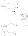
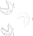
- Figures 1, 2, and 3 show front elevational, side elevational and bottom views of an embodiment of a padlock in a locked state, the padlock being generally indicated by the numeral 10.
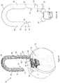
- the padlock 10 comprises a body 12 configured to simultaneously receive a plurality of cylinder locks comprising a first cylinder lock 14 and a second cylinder lock 16.
- Figures 4 and 5 show the arrangement of the internal components of the padlock of figure 1 in the locked state, with some parts hidden or shown transparently.
- Figures 6 and 7 respectively show a bottom view and cut away elevation views of the padlock 10 with a cavity closure 23, first cylinder lock 14 and second cylinder lock 16 removed to reveal a plurality of cylinder lock cavities 90,92 which a connected by a passageway to form a single cavity.
- the cavity closure 23 is in use fastened by fastener 94 in the form of a screw disposed in bore 71 and engaged by threaded portion 96 of the cavity closure 23.
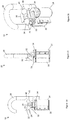
- the plurality of cylinder locks 14, 16 are shown in figure 8 as being received by the body 12 and disposed within the plurality of cylinder lock cavities 90, 92 defined by the body 12.
- the cylinder locks 14,16 are removably fixed and have been inserted through a base 21 of the padlock 10.
- a longitudinal axis 100, 102 of each of the plurality of cylinder locks, which are elongated, are shown aligned with a z direction.
- the plurality of cylinder lock cavities defined by the body 12 are elongated in the z direction and share the longitudinal axes 100,102 with their associated cylinder lock when the cylinder locks 14,16 are received.
- An alternative and otherwise identical embodiment of a padlock is not provided with cylinder locks.
- the cylinder locks 14,16 may be provided for separately. Also shown in figure 3 is drainage hole 86.
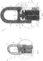
- Figures 9 to 11 show front elevation, side elevation and isometric views respectively of the padlock of figure 1 in the locked state, with some parts hidden and revealing internal components.
- the padlock 10 comprises a shackle 18 in the form of a steel or other metal bar that is turned back on itself to define two arms 26, 28 that respectively terminate at an end in the form of the shackle toe 27 and another end in the form of a shackle heel 29. The two arms 26,28 are shown extending in a z direction.
- the padlock 10 is in a locked state in figures 1 to 7 , in which the shackle 18 of the padlock 10 in fixed or locked.
- the shackle 18 is movably mounted to the body 12 such that the end of arm 26 can be withdrawn from the body 12 by an outwardly translation in substantially the z direction.
- the end 27 can be inserted into the body 12 via a shackle aperture 70 defined by body 12 and captured within the body 12 by a lock mechanism within the body 12.
- the arm 26 can be released by key operation of any one of the plurality of cylinder locks 14,16, which are generally but not necessarily differently cut - for example having different key codes (e.g. blind or bitting codes).
- the padlock 10 may be used, for example, to secure a gate that may need to be opened by agents from two different organisations (e.g. a power company and a water company).
- a key for one of the cylinder locks 14 may be in the possession of one company and a key for the other cylinder lock 16 may be in the possession of another company.
- the shackle 18 comprises a shackle stop receiver 22 by which is received a shackle stop 24.
- the padlock 10 has two shackle stops 24,40 and two shackle stop receivers 22, 38 that operate similarly.
- the shackle stops 24,40 will now be described with reference to only one shackle stop 24 and one shackle stop receiver 22 with the understanding that the description generally applies to both shackle stop receivers 22,38 and both shackle stops 24,40.
- the shackle stop 24 and other shackle stop 40 are each in the form of a sphere and in the present embodiment comprises steel or alternatively another metal, ceramic or generally any suitable material ("ball bearing").
- the shackle stop receiver 22 comprises a section of the shackle 18 that defines a recess 72 ( figure 12 , for example) in the form of a curved groove for the shackle stop 24.
- the shackle stop 24 interferes with the shackle 18 when in the stop position as shown in figures 9 and 11 , and so immobilises it. This prevents the end of arm 26 from being withdrawn from the body 12 and the padlock 10 being configured in an unlocked state.
- the recess 72 may be formed by broaching, grinding or milling a shackle blank, for example.
- the padlock 10 comprises a shackle stop actuator 30, as seen in figures 9 to 11 and detailed in figures 11 to 15 .
- the shackle stop actuator 30 is pivotably mounted by a removable pivot pin 32 that is laterally orientated (shown parallel to a y direction) and so pivotable around a laterally orientated pivot axis 34 shown in figure 4 .
- the pivot pin 32 is disposed in aperture 35 ( figure 21 ) defined by the shackle stop actuator 30, having been inserted through drainage hole 88 shown in figure 7 and retained by interference with fastener 94, in this but not all embodiments a head 95 of fastener 94.
- the shackle stop actuator is pivotable between a plurality of pivot positions.
- the shackle stop actuator 30 is operationally coupled to each of the plurality of cylinder locks 14,16 and actuatable by each of the plurality of cylinder locks 14,16 to pivot the shackle lock actuator 30.
- the shackle stop actuator 30 is pivotable between a plurality of positions.
- a biasing element 42 in the form of a torsion spring is operationally coupled to the shackle stop actuator 30 and the body 12 and is arranged to urge the shackle stop actuator 30 to a pivot position that is a central, locking, or first pivot position, as shown in figures 4,5 , 9 and 10 , for example, that is between two other pivot positions (one of which may be a second pivot position).
- the pin 32 may be integral with the shackle stop actuator 30.
- Figures 17 to 19 show a lateral side 74 of the shackle stop actuator 30.
- the side 74 is associated with the end 27 ("the toe") of the shackle 18.
- the shackle stop actuator 30 comprises a lateral cam surface 46 configured to move the shackle stop 24 to the shackle stop receiver 22. Shown in figures 4,5 , 9,11 , for example, the shackle stop 24 is captured within the shackle stop receiver 22 by the lateral cam surface 46 and so cannot move out of the shackle stop receiver 22.
- the lateral cam surface 46 comprises a capture surface 48 for capturing the shackle stop 24 within the shackle stop receiver 22, which is flanked by flanking surfaces 50, 52 inwardly displaced relative to the capture surface and which are contiguous with the capture surface 48.
- the shackle stop 24 is movably disposed in a conduit 66 defined by the body 12 and having a first conduit opening 59 and a second conduit opening 68, which are at opposite ends of the conduit 66.
- the shackle stop 24 has a clearance fit with respect to the conduit 66.
- the shackle stop receiver 22 is positionable at the first conduit opening 59 and when so positioned the shackle stop 24 is movable along the conduit 66 and into receipt by the shackle stop receiver 22, whereby the shackle stop 24 is disposed in the groove 72, for immobilising the shackle 18.
- the shackle stop 24 When so disposed, the shackle stop 24, being constrained by the interior walls defining conduit 66 interferes with the shackle stop receiver wall 73 ( figure 29 , for example) to stop removal of the shackle toe 27 from shackle receiving passage 31 defined by the body 12 of the padlock 10.
- the shackle stop 24 interferes with the other shackle stop receiver wall 75 to stop further insertion of the shackle toe 27 into the shackle receiving passage 31.
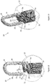
- Figures 14 to 16 show the arrangement of internal components of the padlock of figure 1 in an unlocked state, with the shackle partially extended outwardly.
- the shackle stop 24 can be inwardly moved along the conduit 66, and so removed from the shackle stop receiver 22.
- the padlock 10 comprises a plurality of cylinder lock cams 54, 56, one of which is shown in figures 16 and 17 for example.
- the plurality of cylinder lock cams 54,56 have substantially the shape of a major circular sector.
- the major circular sector has a central angle of approximately 250 to 290 degrees, however it may be lesser or greater in alternative embodiments.
- Cylinder lock cam 54 comprises a caming surface 57 that is followed by a cam follower surface 69 ( figure 17 , for example) of the shackle stop actuator 30.
- Figure 24 shows a view from above of an alternative example of a cylinder lock cam which does not have a substantially more circular section shape.
- the plurality of cylinder lock cams 54,56 are receivable within the plurality of cylinder lock cavities defined by the body 12. As shown in figures 25 to 27 , for example, each of the plurality of cylinder lock cams 54,56 when so received are operable coupled to the plurality of cylinder locks 14,16 and operable by the plurality of cylinder locks 14,16 to pivot the shackle stop actuator 30.
- Cylinder lock cam 54 has a finger 55, as shown in figures 22 and 23 for example. Finger 55 is at the outer perimeter 63 of the cylinder lock cam 54 and is oriented perpendicularly to longitudinal axis 100, 102 of the associated cylinder lock 12,16. Finger 55 is for a key retention function, as described in further detail below. Finger 55 and caming surface 57 are at opposite sides the cylinder lock cam 54.
- a padlock 10 comprise the plurality of cylinder locks 14,16, which are disposed in the plurality of cylinder lock cavities, to which a plurality of cylinder lock cams 54,56 are actuatably coupled thereto.
- One of the two identical cylinder lock cams 54 is shown in detail in figures 22 and 23 .
- the shackle stop actuator 30 is cooperatively arranged with each of the plurality of cylinder lock cams 54, 56 for pivoting the shackle stop actuator 30.
- the distance between the lateral cam surface 46 and the shackle 18 when the shackle stop actuator 30 is at one of the other pivot position ( figures 25 and 26 , for example) on either side of the central pivot position ( figure 27 , for example) is greater than that when the shackle stop actuator 30 is at the central pivot position.
- the shackle stop 22 can be inwardly along the conduit 66, and so removed from the shackle stop receiver 22, but not when the shackle stop actuator 30 is in the pivot position, in which case the shackle stop actuator 30 interferes with inward movement of the shackle stop 22.
- Yet another position similar or identical to the pivot position is on the other side of the central position.
- the lateral cam surface 46 is configured to move the shackle stop 24 to the first conduit opening 59 when the shackle stop actuator 30 is pivoted from one of the plurality of pivot positions, for example the other pivot position shown in figures 25 and 26 , to another one of the plurality of pivot positions, for example the pivot position shown in figure 20 .
- the shackle stop actuator 30 is so pivoted, the sloping flanking surfaces 50 push the shackle stop 24 outwardly along the conduit 66.
- Figure 20 shows a follower engager 84 of the cylinder lock cam 54 rotated into engagement with one of a plurality of cam following surfaces 78,80 of the shackle stop actuator 30.
- Rotational actuation of the shackle stop actuator 30 by the engaged cylinder lock cam 54 causes the shackle stop engager 30 to pivot around the pivot axis 34 through the centre aperture 35 of the shackle stop actuator 30.
- the plurality of cylinder lock cam following surfaces 78,80 are on opposite sides of the shackle stop actuator 30, and each comprise a rounded elongated edge surface 82 that is parallel, in this but not necessarily in all embodiments, to the pivot axis 34.
- the cam following surfaces 78,80 delimit an exterior arcuate surface orientated perpendicularly to the pivot axis 34, the exterior actuate surface clearing the non-engaged cylinder lock cam 56 when pivoted by the engaged cylinder lock cam 54.
- the body 12 defines another conduit 58, shown in figure 5 for example, in which is movably disposed another shackle stop 40 that can interact with another lateral side 76 of the shackle stop actuator 30.
- Figures 20 and 21 show isometric views of the other side 76 of the shackle stop actuator 30.
- the other side 76 is associated with the end 29 ("the heel") of the shackle 18, which in not generally removed from the padlock 10 when the padlock 10 is merely unlocked and subsequently locked.
- Feature 60 of side 76 corresponds to feature 48 of other side 74
- features 61,62 of side 76 correspond to features 52 and 50 of side 74.
- Other stop 40 is moved into receipt by the cam stop receiver 38 when the feature 60 is positioned at the opening 59 ( figure 5 , for example) of other conduit 58.
- Features 64 and 65 of side 76 are at the opening 59 of other conduit 58 when the shackle stop actuator is at a fourth position and a fifth position of the plurality of positions for removing the shackle 18 from the body, as shown in figures 28 and 29 .
- the feature corresponding to the fifth position also indicated by numeral 64 is in the present but not necessarily in all embodiments similar or identical to the fourth position 64, but on the other side of the first or central position.
- Concave features 62 and 64 are inwardly displaced relative to surface 60, and feature 64 more so than feature 62.
- the shackle 18 can be rotated but not removed when the feature 62 is at an opening 68 ( figure 5 ) of another conduit 58.
- the shackle 18 can be removed when either one of the features 64 is at an opening 57 of the other conduit 58.
- arm 28 of shackle 18 comprises a recessed surface 19 defining a shackle stop receiving cavity 77 ( figure 29 , for example).
- the shackle stop 40 is held within the shackle stop receiving cavity 77 by the shackle stop actuator 30 when either one of surfaces 61,62 ( figure 21 ) of the shackle stop actuator 30 is at the 57 ( figure 5 , for example), but not when either one of surfaces 64 and 65 of the shackle stop actuator 30 is at the opening 57.
- the arm 28 cannot be removed from the body 12 when the shackle stop 40 is held within the shackle stop receiving cavity 77 by the shackle stop actuator 30.
- the arm 28 is prevented from spinning within passageway 31 when shackle stop 40 engages flat surface portion 37 opposite shackle stop engager 22, enabling the end 27 to be guided into the aperture 70.
- surface 37 interferes with outward movement of the shackle stop 40, which in turn interferes with and prevents the shackle stop actuator 30 being biased into the central or locking pivot position and the lock cylinder having a received key being moved to a rotary configuration for which the received key can be removed therefrom.
- the shackle 18 is ready to be snap-locked.
- the shackle stop actuator 30 is pivoted to dispose either one of the surfaces 64 and 65 at the opening 57, in which case the shackle stop actuator 30 ceases to interfere with removal of the arm 28 from the shackle stop receiving cavity 77.
- Adjacent end 29 is waist 33 of arm 28, the waist being configured to receive shackle top 40.
- the shackle 18 can spin within shackle receiving passage 31 when shackle stop 40 is received within waist 33 and the shackle 18 is retained within the body 12 by the shackle stop 40.
- Each of the plurality of cylinder lock cams 54,56 are cooperatively arranged with their respective cylinder lock 14,16 to be rotated into contact, specifically a finger 55 thereof, with a lateral side 74,76 of the shackle stop actuator 30.
- the shackle stop actuator 30 interferes with a rotation of a cylinder lock cam because the finger 55 cannot penetrate the lateral side 74,76.
- Contact between finger 55 and the lateral side 76 occurs at the same time as a key is captured by the cylinder lock 14,16 and the shackle stop actuator 30 is at the other pivot position . This may prevent removal of the key when the padlock is unlocked, as in the present embodiment.
- a cam without a finger 55 may be used if this key retention feature is not desired.
Landscapes
- Engineering & Computer Science (AREA)
- Structural Engineering (AREA)
- Refuge Islands, Traffic Blockers, Or Guard Fence (AREA)
- Lock And Its Accessories (AREA)
Applications Claiming Priority (2)
| Application Number | Priority Date | Filing Date | Title |
|---|---|---|---|
| AU2020900399A AU2020900399A0 (en) | 2020-02-13 | A padlock | |
| AU2020267185A AU2020267185B2 (en) | 2020-02-13 | 2020-11-10 | A Padlock |
Publications (2)
| Publication Number | Publication Date |
|---|---|
| EP3865645A1 true EP3865645A1 (fr) | 2021-08-18 |
| EP3865645B1 EP3865645B1 (fr) | 2024-08-21 |
Family
ID=74187158
Family Applications (1)
| Application Number | Title | Priority Date | Filing Date |
|---|---|---|---|
| EP21152090.3A Active EP3865645B1 (fr) | 2020-02-13 | 2021-01-18 | Cadenas |
Country Status (2)
| Country | Link |
|---|---|
| US (1) | US11795734B2 (fr) |
| EP (1) | EP3865645B1 (fr) |
Citations (6)
| Publication number | Priority date | Publication date | Assignee | Title |
|---|---|---|---|---|
| US912773A (en) * | 1908-08-12 | 1909-02-16 | Yale & Towne Mfg Co | Duplex or master-key lock. |
| US1256721A (en) * | 1916-12-21 | 1918-02-19 | William Alfred Murray | Lock. |
| US2487608A (en) * | 1948-05-24 | 1949-11-08 | Master Lock Co | Dual permutation and cylinder padlock |
| JP2002168026A (ja) * | 2000-11-30 | 2002-06-11 | Alpha Corp | 南京錠 |
| US20100154487A1 (en) * | 2008-08-05 | 2010-06-24 | Shik Kui Cheung | Double Cylinder Lock |
| DE202010010397U1 (de) * | 2010-07-14 | 2010-11-04 | Leclercq, Mario | Vorhängeschloss |
Family Cites Families (9)
| Publication number | Priority date | Publication date | Assignee | Title |
|---|---|---|---|---|
| US2834195A (en) * | 1955-08-31 | 1958-05-13 | American Locker Co | Multi-barrel lock |
| CH472564A (de) | 1967-11-18 | 1969-05-15 | Viro Innocenti Spa | Sicherheits-Vorhängschloss mit Schliesszylinder |
| US3813905A (en) * | 1972-11-10 | 1974-06-04 | K Sauder | Master-slave key |
| US4655062A (en) | 1983-01-10 | 1987-04-07 | Lazar Kaufman | System of interconnected lock-cylinders |
| US5839302A (en) * | 1997-06-03 | 1998-11-24 | Chu; Ching-Fa | Locking device with two simultaneously actuated cylindrical plugs |
| JP3616352B2 (ja) * | 2001-06-07 | 2005-02-02 | タキゲン製造株式会社 | 2箇錠型ドアロックハンドル装置 |
| US7856855B2 (en) * | 2006-03-23 | 2010-12-28 | Commando Lock Company, Llc | Lock assembly with removable shackle |
| US9200473B2 (en) * | 2011-07-14 | 2015-12-01 | ABUS August Bremicker Söhne KG | Rekeyable lock cylinder, rekeyable padlock and method of rekeying |
| DE102015117253A1 (de) * | 2015-10-09 | 2017-04-13 | ABUS August Bremicker Söhne KG | Hangschloss |
-
2021
- 2021-01-18 EP EP21152090.3A patent/EP3865645B1/fr active Active
- 2021-02-01 US US17/164,003 patent/US11795734B2/en active Active
Patent Citations (6)
| Publication number | Priority date | Publication date | Assignee | Title |
|---|---|---|---|---|
| US912773A (en) * | 1908-08-12 | 1909-02-16 | Yale & Towne Mfg Co | Duplex or master-key lock. |
| US1256721A (en) * | 1916-12-21 | 1918-02-19 | William Alfred Murray | Lock. |
| US2487608A (en) * | 1948-05-24 | 1949-11-08 | Master Lock Co | Dual permutation and cylinder padlock |
| JP2002168026A (ja) * | 2000-11-30 | 2002-06-11 | Alpha Corp | 南京錠 |
| US20100154487A1 (en) * | 2008-08-05 | 2010-06-24 | Shik Kui Cheung | Double Cylinder Lock |
| DE202010010397U1 (de) * | 2010-07-14 | 2010-11-04 | Leclercq, Mario | Vorhängeschloss |
Also Published As
| Publication number | Publication date |
|---|---|
| US20210254370A1 (en) | 2021-08-19 |
| EP3865645B1 (fr) | 2024-08-21 |
| US11795734B2 (en) | 2023-10-24 |
Similar Documents
| Publication | Publication Date | Title |
|---|---|---|
| US7213425B2 (en) | Padlock having dual unlocking modes | |
| US3789638A (en) | Rotary disc tumbler lock construction | |
| US7334438B2 (en) | Latch assembly | |
| US7121123B2 (en) | Padlock | |
| US7617707B2 (en) | Window-locking assembly | |
| US7353671B2 (en) | Adjustable width coupler latch lock | |
| US4798065A (en) | Lock having a reversible right and left hand bolt | |
| MX2007009485A (es) | Pestillo de cerrojo con manipulacion reversible para cerraduras embutidas. | |
| US20070180871A1 (en) | Storage lock | |
| US7240523B2 (en) | Slide latch assembly | |
| US7213426B2 (en) | Storm door mortise lock that prevents lockout | |
| AU2021356030A1 (en) | Padlock basic assembly kit and padlock system | |
| US12077984B2 (en) | Key and core with cam blocking | |
| EP3865645A1 (fr) | Cadenas | |
| GB2413152A (en) | Cylinder lock with master key capability | |
| AU2020267185B2 (en) | A Padlock | |
| EP1899560A1 (fr) | Verrou pour porte interieure | |
| WO2007019639A1 (fr) | Cadenas comportant un arceau amovible | |
| GB2224071A (en) | Padlock with removable cylinder and re-inforced shackle | |
| US5060493A (en) | Single unit key activated pin lock | |
| AU2018253537B2 (en) | Hasp | |
| AU2006230686A1 (en) | Improved Padlock Assembly and Lock Assembly Remover | |
| KR100192705B1 (ko) | 자물쇠와 열쇠 | |
| JP3090483U (ja) | 錠前付鍵孔閉塞装置 | |
| WO1997033060A1 (fr) | Serrure complete |
Legal Events
| Date | Code | Title | Description |
|---|---|---|---|
| PUAI | Public reference made under article 153(3) epc to a published international application that has entered the european phase |
Free format text: ORIGINAL CODE: 0009012 |
|
| STAA | Information on the status of an ep patent application or granted ep patent |
Free format text: STATUS: THE APPLICATION HAS BEEN PUBLISHED |
|
| STAA | Information on the status of an ep patent application or granted ep patent |
Free format text: STATUS: REQUEST FOR EXAMINATION WAS MADE |
|
| AK | Designated contracting states |
Kind code of ref document: A1 Designated state(s): AL AT BE BG CH CY CZ DE DK EE ES FI FR GB GR HR HU IE IS IT LI LT LU LV MC MK MT NL NO PL PT RO RS SE SI SK SM TR |
|
| 17P | Request for examination filed |
Effective date: 20210728 |
|
| RBV | Designated contracting states (corrected) |
Designated state(s): AL AT BE BG CH CY CZ DE DK EE ES FI FR GB GR HR HU IE IS IT LI LT LU LV MC MK MT NL NO PL PT RO RS SE SI SK SM TR |
|
| GRAP | Despatch of communication of intention to grant a patent |
Free format text: ORIGINAL CODE: EPIDOSNIGR1 |
|
| STAA | Information on the status of an ep patent application or granted ep patent |
Free format text: STATUS: GRANT OF PATENT IS INTENDED |
|
| INTG | Intention to grant announced |
Effective date: 20240313 |
|
| GRAS | Grant fee paid |
Free format text: ORIGINAL CODE: EPIDOSNIGR3 |
|
| GRAA | (expected) grant |
Free format text: ORIGINAL CODE: 0009210 |
|
| STAA | Information on the status of an ep patent application or granted ep patent |
Free format text: STATUS: THE PATENT HAS BEEN GRANTED |
|
| AK | Designated contracting states |
Kind code of ref document: B1 Designated state(s): AL AT BE BG CH CY CZ DE DK EE ES FI FR GB GR HR HU IE IS IT LI LT LU LV MC MK MT NL NO PL PT RO RS SE SI SK SM TR |
|
| REG | Reference to a national code |
Ref country code: GB Ref legal event code: FG4D |
|
| REG | Reference to a national code |
Ref country code: CH Ref legal event code: EP |
|
| REG | Reference to a national code |
Ref country code: DE Ref legal event code: R096 Ref document number: 602021017360 Country of ref document: DE |