EP3865629A2 - Energiemanagementsysteme für bodenfahrzeuge - Google Patents
Energiemanagementsysteme für bodenfahrzeuge Download PDFInfo
- Publication number
- EP3865629A2 EP3865629A2 EP20205965.5A EP20205965A EP3865629A2 EP 3865629 A2 EP3865629 A2 EP 3865629A2 EP 20205965 A EP20205965 A EP 20205965A EP 3865629 A2 EP3865629 A2 EP 3865629A2
- Authority
- EP
- European Patent Office
- Prior art keywords
- electric machine
- hydraulic
- pump
- shaft
- energy
- Prior art date
- Legal status (The legal status is an assumption and is not a legal conclusion. Google has not performed a legal analysis and makes no representation as to the accuracy of the status listed.)
- Granted
Links
Images


Classifications
-
- E—FIXED CONSTRUCTIONS
- E02—HYDRAULIC ENGINEERING; FOUNDATIONS; SOIL SHIFTING
- E02F—DREDGING; SOIL-SHIFTING
- E02F9/00—Component parts of dredgers or soil-shifting machines, not restricted to one of the kinds covered by groups E02F3/00 - E02F7/00
- E02F9/20—Drives; Control devices
- E02F9/2058—Electric or electro-mechanical or mechanical control devices of vehicle sub-units
- E02F9/2062—Control of propulsion units
- E02F9/2075—Control of propulsion units of the hybrid type
-
- E—FIXED CONSTRUCTIONS
- E02—HYDRAULIC ENGINEERING; FOUNDATIONS; SOIL SHIFTING
- E02F—DREDGING; SOIL-SHIFTING
- E02F9/00—Component parts of dredgers or soil-shifting machines, not restricted to one of the kinds covered by groups E02F3/00 - E02F7/00
- E02F9/20—Drives; Control devices
- E02F9/202—Mechanical transmission, e.g. clutches, gears
-
- E—FIXED CONSTRUCTIONS
- E02—HYDRAULIC ENGINEERING; FOUNDATIONS; SOIL SHIFTING
- E02F—DREDGING; SOIL-SHIFTING
- E02F9/00—Component parts of dredgers or soil-shifting machines, not restricted to one of the kinds covered by groups E02F3/00 - E02F7/00
- E02F9/20—Drives; Control devices
- E02F9/2058—Electric or electro-mechanical or mechanical control devices of vehicle sub-units
- E02F9/2091—Control of energy storage means for electrical energy, e.g. battery or capacitors
-
- E—FIXED CONSTRUCTIONS
- E02—HYDRAULIC ENGINEERING; FOUNDATIONS; SOIL SHIFTING
- E02F—DREDGING; SOIL-SHIFTING
- E02F9/00—Component parts of dredgers or soil-shifting machines, not restricted to one of the kinds covered by groups E02F3/00 - E02F7/00
- E02F9/20—Drives; Control devices
- E02F9/22—Hydraulic or pneumatic drives
- E02F9/2246—Control of prime movers, e.g. depending on the hydraulic load of work tools
-
- Y—GENERAL TAGGING OF NEW TECHNOLOGICAL DEVELOPMENTS; GENERAL TAGGING OF CROSS-SECTIONAL TECHNOLOGIES SPANNING OVER SEVERAL SECTIONS OF THE IPC; TECHNICAL SUBJECTS COVERED BY FORMER USPC CROSS-REFERENCE ART COLLECTIONS [XRACs] AND DIGESTS
- Y02—TECHNOLOGIES OR APPLICATIONS FOR MITIGATION OR ADAPTATION AGAINST CLIMATE CHANGE
- Y02T—CLIMATE CHANGE MITIGATION TECHNOLOGIES RELATED TO TRANSPORTATION
- Y02T10/00—Road transport of goods or passengers
- Y02T10/60—Other road transportation technologies with climate change mitigation effect
- Y02T10/62—Hybrid vehicles
Definitions
- This disclosure relates to an energy management system for a hybrid vehicle with an electrically powered hydraulic system.
- an internal combustion engine may provide rotational energy to a hydraulic system via a variator such that the engine shaft can rotate at a different rotational speed than a hydraulic shaft of a hydraulic pump of a hydraulic system.
- a load e.g., transient load
- the functionality or responsiveness of the hydraulic system may deteriorate temporarily for such interlude, which may interfere with the performance of one or more work tasks of a work vehicle (e.g., off-road work vehicle). Accordingly, there is a need for an energy management system for a hybrid vehicle with an electrically powered hydraulic system.
- an energy management system for a ground work vehicle comprises an internal combustion engine for providing a primary rotational energy.
- a motor or electric machine e.g., third electric machine
- a second inverter is configured to control the motor or electric machine.
- a rotatable pump shaft or pump rotor of hydraulic pump is coupled (e.g., controllably or selectively) to an engine shaft of internal combustion engine, a rotor of the electric machine, or both (e.g., via a variator) for receipt of at least a portion of the primary rotational energy, the secondary rotational energy, or both.
- a hydraulic pump supplies hydraulic energy or pressurized hydraulic fluid to a hydraulic system load.
- a vehicle controller establishes a commanded rotor speed for the motor or electric machine based on a target pump rotational speed of a pump rotor or pump shaft for operation of the hydraulic pump at a set point or within an operational region consistent with the hydraulic system load or estimated work task of the vehicle for one or more sampling intervals, where the set point or operational region is defined by a hydraulic pump flow rate versus head characterization curve and where the target pump rotational speed can be independent of the engine shaft rotational speed (e.g. in a first mode).
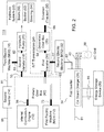
- an energy management system 11 comprises an internal combustion engine 10 that is mechanically, rotationally coupled to a primary gearbox 42.
- the primary gearbox 42 comprises a shaft assembly, transmission or set of gears and associated clutches, such as electrohydraulic clutches or electromechanical clutches.
- the primary gearbox 42 can couple or decouple the rotational energy provided by the internal combustion engine 10 to one or more shafts (56, 58, 60, 70) associated with any of the following components: a first electric machine 12, a first variator 26, and a second variator 18.
- the first electric machine 12 is electrically coupled to the first inverter 34 to control the first electric machine 12 in a motoring mode or to control/support rectification of alternating current generated by the first electric machine 12 in a generating mode.
- the first inverter 34 is electrically coupled to the second electric machine 32 to control the second electric machine 32 in a motoring mode or to control/support rectification of alternating current generated by the second electric machine 32 in a generating mode.
- alternating current (AC) output terminals (81, 83) of the first inverter 34 are coupled to the first electric machine 12 and the second electric machine 32, where the first inverter 34 may comprise a dual inverter.
- the first inverter 34 is electrically coupled to an energy storage device 36.
- the direct current (DC) terminals 85 of the first inverter 34 are coupled to the energy storage device 36.
- One or more vehicle controllers can provide data messages or commanded data to the first electric machine 12, the second electric machine 32, or both to operate in a motoring mode, a generating mode, or a power regeneration mode, where the motoring mode can discharge or draw electrical energy from the energy storage device 36 and where the generating mode can charge the energy storage device 36 with stored electrical energy.
- the energy storage device 36 may comprise a battery, a bank of capacitors, an ultra-capacitor, a combination of batteries and capacitors, or another suitable energy storage device.
- the second inverter 14 is electrically coupled to the third electric machine 16 to control the third electric machine 16 in a motoring mode or to control/support rectification of alternating current generated by the third electric machine 16 in a generating mode.
- the second inverter 14 is electrically coupled to the energy storage device 36 to facilitate charging or discharging of the energy storage device 36.
- alternating current (AC) output terminals 81 of the second inverter 14 are coupled to the third electric machine 16.
- the direct current (DC) terminals 85 of the second inverter 14 are coupled to the energy storage device 36.
- the third electric machine 16 operates as a motor can draw stored electrical energy from the energy storage device 36, as directed by one or more vehicle controllers.
- the third electric machine 16 operates as a generator to provide electrical energy to charge or store in the energy storage device 36.
- the first variator 26 is mechanically, rotationally coupled or decoupled to a second input/output shaft 60 of the primary gearbox 42: (a) to receive primary rotational energy from the internal combustion engine 10, secondary rotational energy from the first electric machine 12, or both, or (b) to transmit primary rotational energy and/or secondary rotational energy (from the internal combustion engine 10 and/or from the first electric machine 12) to the second electric machine 32 and/or to the secondary gearbox 28, (c) to transmit tertiary rotational energy in a braking mode from the traction drivetrain 30 to the first electric machine 12, the second electric machine 32, or both.
- the traction drivetrain 30 refers to the traction drive, driveline, or other mechanical components that transmit torque or rotational energy to the wheels or tracks of the vehicle; the traction drivetrain may also refer to the drivetrain load or vehicle propulsion load associated with the traction drivetrain.
- the first variator 26 is mechanically rotationally coupled or decoupled via hydraulically, mechanically or electromechanically controlled clutches, clutch plates, gears, or other engaging/disengaging rotational members.
- the first variator 26 is mechanically rotationally coupled or decoupled to a rotor of a second electric machine 32 and to a shaft of secondary gearbox 28.
- the secondary gearbox 28 is rotationally, mechanically coupled to the wheels or tracks of the vehicle via a traction drivetrain 30 or driveline.
- the traction drivetrain 30 or driveline may comprise an axle, a transaxle, a differential box, a universal joint, a drive shaft, or other mechanisms or linkages for transferring rotational energy from the secondary gearbox 28 to the wheels or tracks of the vehicle.
- the combination of the first variator 26 and the secondary gearbox may comprise an infinitely variable transmission 24.
- the mechanical coupling or mechanical connection between the first variator 26 and the second electric machine 32 can be referred to as a driveline rotational interface 67 or driveline linkage.
- the mechanical coupling or mechanical connection between the first variator 26 and the secondary gearbox 28 may be referred to as a driveline rotational interface 67 or a driveline linkage, which in certain configurations is integral with the infinitely variable transmission 24.
- the second variator 18 is mechanically, rotationally coupled or decoupled to a first input/output shaft 58 of the primary gearbox 42.
- the primary gearbox 42 can support coupling or decoupling between the first input shaft 56 and the first input/output shaft 58 to facilitate providing secondary rotational energy to the hydraulic pump 20 solely from the third electric machine 16, or to facilitate providing rotational energy jointly from the third electric machine 16 and the internal combustion engine 10.
- the second variator 18 is mechanically, rotationally coupled or decoupled via hydraulically, mechanically or electromechanically controlled clutches, clutch plates, gears, or other engaging/disengaging rotational members: (a) to a rotor of the third electric machine 16, or (b) to a pump shaft or pump rotor of the hydraulic pump 20, or (c) both to the rotor of the third electric machine 16 and the hydraulic pump 20 simultaneously.
- a discharge or output of the hydraulic pump 20 has a hydraulic line or conduit coupled to the hydraulic system 22.
- the hydraulic pump 20 may comprise one or more hydraulic pumps that are distributed within a hydraulic system 22 that supports one or more implements.
- the hydraulic system 22 may be configured in accordance with various examples that can be applied separately or cumulatively.
- the hydraulic system 22 may comprise the hydraulic pump 20 and one or more hydraulic components, such as one or more electrohydraulic cylinders that are associated with an implement or tool of a work vehicle.
- the hydraulic pump 20 may provide pressurized hydraulic fluid, directly or indirectly, to one or more electrohydraulic cylinders via hydraulic lines, feedback lines, recirculation lines, redundant lines, connections, electrohydraulic valves, and accumulators that form a suitable hydraulic network for operation of a mobile implement of a work vehicle that can be controlled by an operator and/or a data processing system.
- a first electrohydraulic cylinder associated with moving (e.g., raising or lowering) a boom of a boom system 50 or arm (of an implement) relative to the ground work vehicle.
- the hydraulic system 22 may comprise a second electrohydraulic cylinder associated with moving a bucket of a bucket system 52, fork or another implement tool.
- the hydraulic system 22 may comprise a dual electrohydraulic cylinder for a hydraulic steering system 54 or controlling the steering system 54 or yaw angle of the wheels of the vehicle.
- the primary gearbox 42, the first variator 26 and the second variator 18 are combined in an aggregate transmission system.
- an energy management system 11 for a ground vehicle comprises an internal combustion engine 10 for providing a primary rotational energy.
- a first electric machine 12 e.g., generator
- a second electric machine 32 e.g., motor
- a third electric machine 16 is configured to receive a portion of the primary rotational energy in a generating mode or to provide secondary electrical energy to replace or supplement the primary rotational energy in a motoring mode.
- a first inverter 34 may comprise a dual inverter with a primary inverter that is configured control the first electric machine 12 in a motoring mode, a generating mode, a braking/regeneration mode, or any combination of the above modes.
- the primary inverter is configured to rectify alternating current output by the first electric machine 12.
- the first inverter 34 may comprise a dual inverter with a secondary inverter to control the second electric machine 32 in a motoring mode, a generating mode, a braking/regeneration mode, or any combination of the above modes.
- a second inverter 14 is configured to control the third electric machine 16.
- a rotatable pump shaft or pump rotor of hydraulic pump 20 is coupled (e.g., controllably or selectively) to an engine shaft of internal combustion engine 10, a rotor of the third electric machine 16, or both for receipt of at least a portion of the primary rotational energy, the secondary rotational energy, or both.
- the hydraulic pump 20 supplies hydraulic energy to a hydraulic system 22 load (e.g., implement load).
- the hydraulic system 22 may include hydraulic components or hydraulic loads associated with any of the following implement or vehicle systems: (a) hydraulic boom system 50, (b) hydraulic tool system (e.g., hydraulic bucket system 52, fork or tool system), and (c) hydraulic steering system 54.
- a vehicle controller 409 establishes a commanded rotor speed for (e.g., application to the second inverter 14 for control of) the third electric machine 16 based on a target pump shaft rotational speed for operation of the hydraulic pump 20 at a set point or within an operational region consistent with an observed hydraulic load (e.g., load curve 502 in FIG. 5 ) or estimated work task of the vehicle for one or more sampling intervals, which can effectively shift or temporarily modify the observed hydraulic load curve (e.g., by a fixed amount upward or downward with respect to the vertical axis along the entire hydraulic load curve) for one or more sampling intervals or for a vehicle session at a worksite.
- an observed hydraulic load e.g., load curve 502 in FIG. 5
- estimated work task of the vehicle for one or more sampling intervals
- the set point or operational region of the hydraulic pump 20 is defined by a hydraulic pump flow rate 510 versus head 508 characterization curve (e.g., pump output curve 506 in FIG. 5 ) where the target pump rotational speed can be independent of the engine shaft rotational speed.
- the target pump rotational stepped can be independent of the engine shaft rotational speed if and to the extent that the engine shaft is coupled or decoupled from the pump shaft or pump rotor of the hydraulic pump 20 for one or more sampling intervals to address transient hydraulic loads on the hydraulic system 22 in a first mode of operation of the energy management system 11.
- the first mode may comprise an electrically driven mode that is solely electrically driven by the third electric machine 16 or motor. Further, in the first mode the target rotational speed of the pump shaft or pump rotor is generally independent of the power output of the internal combustion engine 10.
- the second mode of operation may comprise an engine driven mode that is solely mechanically driven by the internal combustion engine 10.
- a variator e.g., second variator 18
- the hydraulic pump 20 such that the pump rotor or pump shaft is rotationally, mechanically coupled to the engine shaft in the second mode.
- third mode of operation may comprise a hybrid of the first mode and the second mode.
- the third mode may comprise the joint or simultaneous operation of an electrically driven mode and an engine-driven mode.
- a variator e.g., second variator 18
- a pump rotor or pump shaft is rotationally simultaneously coupled to the rotor of the electric machine (e.g., 16) and to the engine shaft. That is, in a third mode or torque-assist mode, the primary rotational energy and the secondary rotational energy are applied simultaneously to the pump rotor or pump shaft.
- the vehicle controller 409 or variator module 422 controls the second variator 18 to operate in the first mode, the second mode or the third mode.
- the primary gearbox 42 comprises a gearbox, a transmission, a shaft assembly, a gearbox or shaft assembly with clutches, clutch plates or rotational members that are actuated, activated or deactivated by control signals from one or more vehicle controllers (e.g., 409 in FIG. 4A ).
- a primary gearbox 42 has a first input shaft 56 coupled to receive the primary rotational energy from an engine shaft of the internal combustion engine 10.
- the primary gearbox 42 has a first input/output shaft 58, a second input/output shaft 60, and a third input/output shaft 70.
- the primary gearbox 42 may comprise any of the following engaging shaft portions, wheels, gears, clutches, or mechanical assemblies for coupling or decoupling any combination of the first input shaft 56, the first input/output shaft 58, the second input/output shaft 60, and/or the third input/output shaft 70 in response to control data messages from any of the following components: vehicle controller 409, variator module 422, engine monitoring module 456, hydraulic control module 406, and task manager module 450.
- each electric machine may comprise a motor, a generator, an alternator, an alternating current motor, a three-phase motor, an integral permanent magnet motor, or an induction motor.
- each electric machine may operate in a generating mode, a motoring mode, or a braking or regeneration mode, consistent with the control signals of a motor controller or inverter (34, 14) coupled to a corresponding electric machine (12, 32, 16).
- a first electric machine 12 (e.g., generator) is configured to receive a portion of the primary rotational energy from the internal combustion engine 10 via the primary gearbox 42, if the primary gearbox 42 couples the first input shaft 56 to the third input/output shaft 70.
- a second electric machine 32 (e.g., motor) is configured to provide secondary rotational energy to the first variator 26 via driveline rotational interface 67 to replace or supplement the primary rotational energy.
- the second electric machine 32 is configured to provide secondary rotational energy to replace the primary rotational energy if the first input shaft 56 is decoupled from the second input/output shaft 60.
- the first inverter 34 can draw electrical current from the energy storage device 36 to power the second electric machine 32 in the motoring mode.
- the second electric machine 32 is provided to supplement the primary rotational energy of the internal combustion engine 10 in a torque-assist or torque supplemental mode if the first input shaft 56 is coupled to the second input/output shaft 60 and if the rotor of the second electric machine 32 is coupled to the second/input output shaft 60 via the first variator 26 or electronic infinitely variable transmission 24.
- a third electric machine 16 (e.g., motor) is configured to receive a portion of the primary rotational energy or to provide secondary electrical energy to replace or supplement the primary rotational energy.
- the second inverter 14 can draw electrical current from the energy storage device 36 to power the third electric machine 16 in the motoring mode.
- a hydraulic system load of the hydraulic system 22 is coupled to the first/input output shaft 58 for receipt of at least a first portion of the primary rotational energy; the hydraulic system load of the hydraulic system 22 is coupled to the implement rotational interface 63 for receipt of secondary rotational energy.
- the rotatable pump shaft or pump rotor of the hydraulic system 22 is coupled to the rotatable shaft of the third electric machine 16.
- the hydraulic system load of the hydraulic system 22 comprises a hydraulic load of an implement of the vehicle.
- the second inverter 14 is configured to control the commanded rotor speed of the third electric machine 16 in a motoring mode to operate the hydraulic pump 20 at a target operational set point 505 (e.g., in FIG. 5 ) or within the target operational region 504, where the commanded rotor speed is independent of the engine speed of an engine shaft of the internal combustion engine 10.
- the vehicle controller 409 in FIG.
- the second inverter 14 estimates or provides the commanded rotor speed of the third electric machine 16 to the second inverter 14; the second inverter 14 is configured to control the third electric machine 16 to rotate a pump shaft or rotor shaft of a hydraulic pump 20 of the hydraulic system 22, (via a second variator 18), at a target operational set point or within a target operational region of the hydraulic pump 20 defined by the hydraulic pump flow rate 510 versus head 508 characterization curve, such as the characterization curve of FIG. 5 or variants thereof.
- the target rotational speed of the pump shaft or pump rotor can be estimated based on the one or more of the following parameters: (a) a target operational set point of a pump output curve 506, (b) a target operational region of the hydraulic pump 20, (c) hydraulic system load curve 502, (d) an identified task or classified work task of an implement, or modification of the hydraulic system load curve based on the identified task or classified work task for a work session or one or more sampling intervals of work vehicle operation at one or more worksites; (d) historic or observed average, median, mode implement hydraulic loads or task loads for a work session, a work site, or one or more sampling intervals.
- the target rotational speed of the pump shaft or pump rotor can be generally independent of the power output of the internal combustion engine 1.
- the engine shaft and the rotor of the third electric machine 16 rotate generally synchronously at the same rotational speed.
- the second variator 18 is coupled between the hydraulic pump 20 and the electric machine such that the pump rotor or pump shaft is rotationally, mechanically coupled to the rotor of the electric machine (e.g., third electric machine 16) via the rotational interface 63.
- the second variator 18 is coupled (or decoupled) between the internal combustion engine 10 and the hydraulic pump 20 such that the pump rotor or pump shaft (of the hydraulic pump 20) is rotationally, mechanically coupled to the engine shaft.
- the primary gearbox 42 is coupled (or decoupled) between the internal combustion engine 10 and the second variator 18 such that the engine shaft (e.g., coupled to input shaft 56) is coupled (or decoupled) to an input shaft (e.g., associated with first input/output shaft 58) of the variator 18 to contribute primary rotational energy to the hydraulic pump 20.
- the engine shaft e.g., coupled to input shaft 56
- an input shaft e.g., associated with first input/output shaft 58
- the engine size or engine power of the internal combustion engine 10 can be decreased independently of the hydraulic load and the target operational set point or target operational region required for efficient operation of the hydraulic pump 20 associated with a corresponding task load profile.
- the reduction of engine size or engine power can be accomplished by reduction of engine torque versus engine speed curve, or a modification or translation of the engine torque versus engine speed curve, for example.
- the reduction of engine power can be achieved by the engine controller 410 or vehicle controller 409 limiting the engine 10: (1) to operate in a certain target operating region of the engine torque versus engine speed curve, (2) by adjusting fuel injection, fuel metering, and/or (3) by reduction of intake air pressure or boost pressure, relative to atmospheric pressure, associated with turbocharging or supercharging components of the engine 10.
- the engine monitoring module 456, alone or together with the engine controller 410 may receive or estimate the engine power output or engine load for a sampling interval or work session based on measured or observed torque data and rotational speed data for the engine shaft of the engine 10.
- a task load manager module 450 or vehicle controller 409 may classify or identify a task or task load for a sampling interval or a session to modify, estimate or determine a hydraulic load or observed hydraulic system load of the hydraulic system 22 associated with one or more vehicle implements.
- the task load manager module 450 may function, alone or together, with the hydraulic control module 406 to modify, enhance or refine an initial hydraulic load estimate estimated by the hydraulic control module 406.
- a vehicle controller 409 or task manager module 450 may estimate or determine a task load or hydraulic load of the hydraulic system 22 of the work vehicle, which may be associated with or correlated to one or more of the following tasks or work functions, which can be executed separately or together.
- the vehicle controller 409 or task manager module 450 determines, identifies or classifies that the work vehicle is engaged in a rise/run operation in which the load has a hydraulic implement load component (e.g., rise component) for moving/raising the implement with respect to ground (or above the ground) and traction drive load component (e.g., run component) for moving the vehicle with respect to the ground.
- a hydraulic implement load component e.g., rise component
- traction drive load component e.g., run component
- the vehicle controller 409 or task manager module 450 determines, identifies or classifies a rise/run operation that comprises raising a reference point on the implement from a first height to and second height, with a zero mass load or a reference mass load, and accelerating the vehicle along a path from a first position (e.g., two or three dimensional coordinates) to a second position.
- the vehicle controller 409 or task manager module 450 determines, identifies or classifies that: (a) the rise/run operation relates to an implement that comprises an arm, a boom of a boom system 50, and tool or bucket of a bucket system 52 of excavator and (b) the rise/run operation has a reference hydraulic system load, a reference hydraulic pressure, and a reference hydraulic flow rate for one or more hydraulic actuators, where the reference values may comprise historic values, mean, mode, median or other statistical analysis for a session, worksite, affiliated work session at corresponding worksites, or the like.
- the vehicle controller 409 or task manager module 450 determines, identifies or classifies that: (a) the rise/run operation relates to an implement that comprises an arm or bucket of a bucket system or fork of a loader and (b) the rise/run operation has a reference hydraulic system load, a reference hydraulic pressure, and a reference hydraulic flow rate for one or more hydraulic actuators, where the reference values may comprise historic values, mean, mode, median or other statistical analysis for a session, worksite, affiliated work session at corresponding worksites, or the like.
- the vehicle controller 409 or task manager module 450 determines, identifies or classifies that the rise/run operation requires a minimum rotational speed of hydraulic pump 20 of the vehicle or a requisite operational range of rotational speed that is defined by a lower rotational speed limit, an upper rotational speed limit, or both.
- the vehicle controller 409 or task manager module 450 determines, identifies or classifies that the rise/run operation requires a first minimum rotational speed (e.g., approximately 1600 rpm) or first rotational speed range (e.g., approximately 1400 rpm to 1800 rpm) of the hydraulic pump 20 of the vehicle, whereas the transmission 24 requires a second minimum rotational speed (e.g., approximately 1100 rpm) or second rotational speed range (e.g., approximately 1000 rpm to 1200 rpm) of the hydraulic pump 20, wherein the first minimum rotational speed is greater than the second minimum rotational speed.
- a first minimum rotational speed e.g., approximately 1600 rpm
- first rotational speed range e.g., approximately 1400 rpm to 1800 rpm
- second minimum rotational speed e.g., approximately 1100 rpm
- second rotational speed range e.g., approximately 1000 rpm to 1200 rpm
- the vehicle controller 409 or task manager module 450 determines, identifies or classifies that, the vehicle comprises a loader that is digging into a pile of material that demands that internal combustion engine 10 operate at or near a peak torque corresponding to respective engine shaft speed, unless the engine operates a lower engine shaft speed below the peak torque with supplemental torque provided by the first inverter 34 controlling the first electric machine 12.
- the vehicle controller 409 or task manager module 450 determines, identifies or classifies that: (a) the vehicle is braked and the first electric machine 12 and the second electric machine 32 operate in a generating mode to oppose the movement of the vehicle along the ground via traction drivetrain 30 and to generate alternating current (AC) electrical energy for application to the first inverter 34, which in turn rectifies the AC into DC for application to the energy storage device 36; (b) the vehicle controller 409 tracks or stores records of the braking or regenerating mode and a duration that the work vehicle is plugged into or connected to an optional AC line 40 on or associated with the optional AC power grid 38.
- the AC line 40 and the AC power grid are optional, as indicated by the dashed lines and may be deleted from certain embodiments.
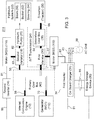
- the energy management system 111 of FIG. 2 is similar to the energy management system 11 of FIG. 1 , except in the system 111 of FIG. 2 the first inverter 34 further comprises a power supply or on-board charger 35.
- the first inverter 34 may further comprise a power supply or on-board charger 35 for converting an alternating current signal associated with an alternating current (AC) power line 38 or AC power grid 38 to direct current (DC) signal power charging an energy storage device 36 of the vehicle.
- AC alternating current
- DC direct current
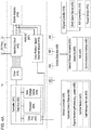
- the energy management system 211 of FIG. 3 is similar to the energy management system 11 of FIG. 1 , except in the system 211 of FIG. 3 each of electric machines (112, 116, 132) is defined as a motor or a generator, although this does not technically restrict or limit the motor from operating as generator, or vice versa.
- the first electric machine 12 (of FIG. 1 ) is designated as a generator 112; the second electric machine 32 (of FIG. 1 ) is designated as a motor 132; the third electric machine 16 (of FIG. 1 ) is designated as motor 116.
- Like reference numbers in FIG. 1 and 3 indicate like elements or features.
- the first inverter 34 comprises a dual inverter having primary alternating current (AC) terminals 81, secondary AC terminals 83, and DC terminals 85.
- the DC terminals 85 are coupled to the energy storage system 36.
- the primary AC terminals 81 are coupled to the generator 112 and the secondary AC terminals 83 are coupled to the motor 132.
- the inverter 34 generates motor command data for the motor 132 in a torque control mode or speed control mode based on data messages of the vehicle controller 409.
- the energy management system (11, 111, 211) comprises an energy storage device 36.
- a first inverter 34 is coupled to the energy storage device 36.
- the second electric machine (32, 132) is configured for control by the inverter.
- the second electric machine (32, 132) is configured to provide tertiary rotational energy to replace or supplement the primary rotational energy of the internal combustion engine 10.
- the second electric machine (32, 132) can replace or supplement the primary rotational energy of the internal combustion engine 10, where an engine size, engine power, fuel consumption, and emissions of the internal combustion engine 10 is minimized or decreased in accordance with any of the following: an engine compression is decreased, a stoichiometric ratio of the fuel-air mixture is reduced, a boost pressure of a turbo charger or electrically driven boost machine reduced or eliminated (e.g., run as naturally aspirated engine), the fuel injection or fuel metering is adjusted.
- the second electric machine (32, 132) has greater power capacity than the third electric machine (16, 116).
- the first inverter 34 is configured to convert auxiliary alternating current (AC) into direct current (DC) for charging the energy storage device 36 if the vehicle is stationary or in a park mode (as sensed by a motion sensor in communication with the vehicle data bus) and if the auxiliary alternating current is provided from a connection to an alternating current line 40 of an alternating current power grid 38 or network.
- the first inverter 34 comprises a dual inverter that is coupled to the first electric machine 12, or the second electric machine 32, or both.
- the first electric machine (12, 112) and the second electric machine (32, 132) can operate in a motoring mode to supplement or replace the primary rotational energy of the internal combustion engine 10.
- an electrically driven infinitely variable transmission 24 comprises a first variator 26 for receiving secondary rotational energy of the first electric machine 12, the second electric machine 32 or both via (input) shafts (60, 67) or rotational interfaces of the electrically driven infinitely variable transmission 24.
- the first electric machine 12, or the second electric machine 32 can separately or together operate in the motoring mode to supplement or replace the primary rotational energy with additional torque to prevent stall of the internal combustion engine 10 during transient loads or transient traction drive loads.
- An electrically driven/supplemented infinitely variable transmission 24 or a first variator 26 is configured to transmit the primary rotational energy of the internal combustion engine 10 to the first electric machine 12, the second electric machine 32 or both via shafts (56, 60, 67, 70) or rotational interfaces of the electrically driven infinitely variable transmission 24 and the primary gearbox 42.
- the first electric machine 12, or the second electric machine 32 can separately or together operate (in the generating mode.
- a traction drive load 30 is associated with propulsion of the work vehicle with respect to the ground.
- a vehicle controller 409 (in FIG. 4A ) is adapted to for simultaneously generating an primary commanded speed command for the second inverter 14 to apply to the third electric machine 16 (or motor 116) and for generating a secondary commanded speed command for the first inverter 34 to apply to the first electric machine 12 or the second electric machine 32, wherein the primary commanded speed command is different from the secondary commanded speed command; wherein the primary commanded speed command addresses the hydraulic load of the hydraulic system 22 and wherein the secondary speed command addresses the traction load of traction drivetrain 30 simultaneously.
- FIG. 4A is a block diagram of an inverter and a vehicle electronics system for a ground work vehicle.
- the inverter of FIG. 4A may comprise the primary or secondary inverter of the first inverter 34 or second inverter 14.
- an inverter 14 comprises a controller 401 coupled to a driver 414.
- the driver 414 is coupled to a switching circuit 415, where the switching circuit 415 may have direct current (DC) terminals 416 and alternating current (AC) terminals 417, such as pulse-width-modulation (PWM) AC output signals for a three phase electric machine 418.
- the AC terminals 417 or the switching circuit 415 may be coupled to an electric machine 418.
- a rotor position/speed detection module 419 is coupled to the switching circuit 415 and the controller 401 to provide control feedback to the controller 401.
- the controller 401 comprises an electronic data processor 404, a data storage device 405 and a data port 403 that are coupled to a data bus 402.
- the electronic data processor 404, the data storage device 405, and the data port 403 may communicate with each other via the data bus 402.
- the electronic data processor 404 may comprise a microcontroller, a microprocessor, a programmable logic array, a field programmable gate array, an application specific integrate circuit, a digital signal processor, a logic circuit, an arithmetic logic unit, or the like.
- the data storage device 405 may comprise electronic memory, nonvolatile electronic random access memory, a magnetic data storage device, an optical data storage device, a hard disk, or the like.
- a rotor position/speed detection module 419 detects a rotor position of the electric machine 418 and may provide a feedback signal based on the rotor position of the controller 401.
- the electric machine 418 may comprise one or more of the following: a first electric machine 12, a generator 112, a second electric machine 32, motor 132, a third electric machine 16 and motor 116.
- a vehicle controller 409 or another data processor may send a commanded speed of the electric machine, such as the third electric machine 16, or a commanded torque of the electric machine to control precisely the hydraulic pump 20 to a target operating point or target operating region 504 consistent with an observed load (e.g., identified or classified load task) on the hydraulic system 22 that the pump supplies with pressurized hydraulic fluid/energy.
- a commanded speed of the electric machine such as the third electric machine 16, or a commanded torque of the electric machine to control precisely the hydraulic pump 20 to a target operating point or target operating region 504 consistent with an observed load (e.g., identified or classified load task) on the hydraulic system 22 that the pump supplies with pressurized hydraulic fluid/energy.
- the second inverter 14 may be coupled to the vehicle data bus 408 via a data port 403. Further, one or more vehicle controller(s) 409, an engine controller 410, a variator sensor assembly 424, and optional variator sensors 426 may be coupled to the vehicle data bus 408. As illustrated in FIG. 4A , the variator sensor assembly 424 comprises an analog-to-digital converter 428 to convert measured, observed signals into digital signals and a communications interface 430 to interface with the vehicle data bus 408.
- the communications interface 430 may comprise data buffer for storing a set of measured, observed signals for transmission via a transceiver.
- one or more hydraulic pressure sensors 451, hydraulic flow sensors 452, hydraulic linear position sensors 453, and motion sensor 454 may be coupled to the vehicle data bus 408. Further, each of the above optional sensors (451, 452, 453, 454) may be associated with an analog-to-digital converter to convert measured, observed signals into digital signals and a communications interface to interface with the vehicle data bus 408.
- the communications interface may comprise data buffer for storing a set of measured, observed signals for transmission via a transceiver; such analog-to-digital converter and communications interface may be similar to or identical to those illustrated in conjunction with the variator sensor assembly.
- each hydraulic pressure sensor 451 and each hydraulic flow sensor 452 is associated with a corresponding hydraulic actuator, hydraulic cylinder or electrohydraulic cylinder of the hydraulic system 22, such as the hydraulic boom system 50, the hydraulic bucket system 52 or other hydraulic implement system, actuator or component.
- the engine controller 410 may receiver sensor measurements or observations from a shaft speed sensor 455, and a torque sensor 413, directly or indirectly, via an optional analog-to-digital converter 412.
- the shaft speed sensor 455 may comprise a magnetic field sensor that senses a magnetic field or change in magnetic field associated with one or more magnets in or secured to an engine shaft or related rotational component of the engine 10.
- the shaft speed sensor 455 can provide an observed rotational speed of the engine shaft of the engine 10 during one or more sampling intervals, while the torque sensor 413 can simultaneously an observed torque associated with the engine shaft to estimate the available engine power for driving the observed or current hydraulic load of the hydraulic pump 20 and hydraulic system 22. If the available engine power or observed torque is less than a critical threshold, the engine controller 410 or vehicle controller 409 can control the energy management system to operate in third mode or torque assist mode to provide secondary rotational energy from an electric machine to the hydraulic pump 20 (combined with the primary rotational energy from the engine 10).
- a first hydraulic pressure sensor 451 and first hydraulic flow sensor 452 are associated with a first actuator (e.g., first electrohydraulic cylinder) having an anchored end that is attached (rotatably attached) to a vehicle body and a linearly movable end that is attached to an implement (e.g., arm or boom of the boom system 50) for moving (e.g., raising or lowering the boom).
- a first actuator e.g., first electrohydraulic cylinder
- a second hydraulic pressure sensor 451 and second hydraulic flow sensor 452 are associated with a second actuator (e.g., second electrohydraulic cylinder) having an anchored end that is attached (rotatably attached) to an implement (e.g., arm or boom system 50) and a linearly movable end that is attached to an implement tool (e.g., bucket, fork, cutter, or another tool) for moving, guiding or manipulating a path of the implement tool.
- a second actuator e.g., second electrohydraulic cylinder
- the first hydraulic pressure sensor 451 and the first hydraulic flow sensor 452 are configured to observe mass/load in the implement tool (e.g., loader bucket).
- an optional hydraulic cylinder linear position sensor 453 observes the extension, retraction or both of the linearly moveable end of the first electrohydraulic cylinder to detect changes from a first height to a second height, where the second height is greater than a first height.
- the, an optional hydraulic cylinder linear position sensor 453 is configured to observe height movements/maintenance that impact load for repetitive operations).
- a motion sensor 454 may comprise a ground speed sensor, velocity sensor, or acceleration sensor.
- the motion sensor 454 may comprise any of the following an odometer, accelerometer, gyroscope, inertial measurement unit (IMU) a satellite navigation receiver (e.g., GPS receiver), or the like.
- IMU inertial measurement unit
- satellite navigation receiver e.g., GPS receiver
- the vehicle controller 409 comprises an electronic data processor 404, a data storage device 405 and a data port 403 that are coupled to a data bus 402.
- the electronic data processor 404, the data storage device 405, and the data port 403 may communicate with each other via the data bus 402.
- the vehicle controller 409 may comprise one or more of the following modules: a hydraulic control module 406, an engine monitoring module 456, a variator module 422, and a load manager module or task manager module 450.
- the foregoing modules may be optional because they are indicated in dashed lines in FIG. 4A and in FIG. 4B .
- Each module may comprise software, electronic hardware, or both.
- the software may comprise software instructions, modules, libraries, data files or other data structures that are stored in the data storage device 405 (of vehicle controller 409 in FIG. 4B ) for execution, retrieval, or processing by the electronic data processor 404 or another controller.
- the software can be realized or modeled as electronic hardware in accordance with Boolean logic, equivalent circuits, digital or analog circuits, or the like.
- the task manager module 450 comprises any of the following: a task identifier, a task classifier, a load manager, and/or a load estimator for an implement, an actuator, or system of a work vehicle.
- the hydraulic control module 406 may estimate a hydraulic load of one or more of the following for one or more sampling intervals or a work session of the work vehicle: current hydraulic load of one or more hydraulic systems 22, current hydraulic load associated with one or more hydraulic pumps 20, a hydraulic output curve (e.g., expressed as an equation, a data set, historic measurements, pump manufacturer specifications or other data structure) associated with one or more hydraulic pumps, and current hydraulic load associated with one or more actuators or hydraulic cylinders of the implements of the work vehicle.
- the vehicle controller 409, the hydraulic control module 406 or the task manager module 450 alone or collectively, determine, generate or provide an appropriate commanded torque or commanded speed to be communicated to the second inverter 14 and its controller 401.
- the vehicle controller 409 or the task manager module 450 comprises an algorithm, a module or software instructions to keep the rotor speed of the electric machine (418, 12, 16, 32, 112, 116, 132) in the target operating point or region of the hydraulic pump 20 (which is independent of the engine shaft speed in the first mode), among other things.
- a task manager module 450 of the vehicle controller 409 allows the target operating point or region of the hydraulic pump 20 to be shifted or to be aligned with the particular operational task that the vehicle (e.g., loader, excavator or other work vehicle) is engaged in.
- the task manager module 450 or vehicle controller 409 to identifies a current task for a work session (or for one or more sampling intervals) from a set of potential task classifications, such as the rise/run task, a digging task, or another defined task, where each task is associated with corresponding implement load level or hydraulic system load level (e.g. intensity level).
- the task manager module 450 may process, express, rank or categorize the hydraulic load level as a mode, median, average, mean hydraulic load level based on historic measurements for the worksite, work vehicle or for a fleet or group of work vehicles at a worksite.
- the vehicle controller 409 or task manager module 450 determines or estimates that each task may be associated with any combination of the following task parameters: reference duration, reference hydraulic flow rate, reference hydraulic pressure, reference load or mass associated with implement tool, reference height differential or height increase of the implement tool, vehicle acceleration, vehicle speed or velocity.
- the vehicle controller 409 or task manager module 450 identifies or classifies an observed task of the vehicle for one or more corresponding time intervals based on various sensor measurements (as described in this disclosure) or observations that are indicative of the above task parameters or reference task parameters.
- the vehicle controller 409 or task manager module 450 may apply a corresponding target operating point or target operational region of the hydraulic pump 20, such as pump shaft rotational speed associated with the identified or classified task for one or more respective time intervals; hence, ultimately output the proper commanded rotor speed for the second inverter 14 to control precisely the rotor speed of the third electric machine 16 or motor that drives the hydraulic pump 20, independently of the engine shaft speed of the internal combustion engine 10 (e.g., in a first mode of operation).
- a target operating point or target operational region of the hydraulic pump 20 such as pump shaft rotational speed associated with the identified or classified task for one or more respective time intervals
- the commanded rotor speed (for the second inverter 14 to apply to the third electric machine 16 that drives the hydraulic pump 20 via the second variator 18) is associated with a corresponding target operating point (or target operating region 504 of the hydraulic pump 20) and the classified or identified task (or its associated load) for one or more respective sampling intervals or a work session for a corresponding worksite.
- the commanded rotor speed may be stored in look-up table, in an inverted file, a database or another data structure.
- the vehicle controller or task manager module 450 receive sensor data from sensors coupled to the vehicle data bus 408 to estimate: (a) the pump shaft or pump rotor speed of the hydraulic pump 20, (b) a rotor position speed of the third electric machine 16, and (c) sensor data from the rotor position/speed detection module 419 or the inverter 14.
- the rotor position/speed detection module 419 or the inverter 14 measures the current and/or voltage measurements at the alternating current (AC) terminals (417, 81, 83) between the second inverter 14 output and the third electric machine 16.
- AC alternating current
- an optional hydraulic pump rotor speed sensor is coupled to the vehicle data bus 408 to provide feedback of the pump shaft rotational speed for the vehicle controller 409, the inverter controller 401, or both.
- the vehicle controller 409 or variator module 422 uses the gear ratio or effective gear ratio of the second variator 18 to estimate the pump rotor speed (e.g., gear rotational speed or displacement) or pump shaft speed, impeller rotational speed of the hydraulic pump 20, which may impact the estimation of the hydraulic load for one or more sampling intervals.
- the variator module 422 alone or together with a transmission controller on the vehicle data bus 408, may track the coupling or decoupling between or among the rotatable interfaces, such as input/output shafts (56, 58, 60, 62, 63, 64, 67, 70) of the first variator 18, the second variator 26, and the primary gearbox 42 to facilitate proper control and supervision of the vehicle controller 409 for various modes of operation.
- a task load may comprise a hydraulic load of a hydraulic pump 20 or hydraulic system 22 of an implement engaged in one or more of the following tasks, which can be executed separately or together.
- the vehicle engages in a rise/run operation in which the load has a hydraulic implement load component (e.g., rise component) for moving/raising the implement with respect to ground and traction drive load component (e.g., run component) from moving the vehicle with respect to ground.
- a rise/run operation comprises raising a reference point on the implement from a first height to and second height, with a zero mass load or a reference mass load, and accelerating the vehicle along a path from a first position (e.g., two or three dimensional coordinates) to a second position.
- the rise/run operation relates to an implement that comprises an arm, a hydraulic boom system 50, and hydraulic bucket system 52 of a loader, an excavator, or another work vehicle.
- the rise/run operation relates to an implement that comprises an arm or hydraulic bucket system 52 or fork of a loader.
- the rise/run operation requires a minimum rotational speed of hydraulic pump 20 of the vehicle or a requisite operational range of rotational speed that is defined by a lower rotational speed limit, an upper rotational speed limit, or both.
- the rise/run operation requires a first minimum rotational speed (e.g., approximately 1600 rpm) or first rotational speed range (e.g., approximately 1400 rpm to 1800 rpm) of the hydraulic pump 20 of the vehicle, whereas the transmission 24 for ground propulsion requires a second minimum rotational speed (e.g., approximately 1100 rpm) or second rotational speed range (e.g., approximately 1000 rpm to 1200 rpm) of the hydraulic pump 20, wherein the first minimum rotational speed is greater than the second minimum rotational speed.
- first minimum rotational speed e.g., approximately 1600 rpm
- first rotational speed range e.g., approximately 1400 rpm to 1800 rpm
- second minimum rotational speed e.g., approximately 1100 rpm
- second rotational speed range e.g., approximately 1000 rpm to 1200 rpm
- the vehicle comprises a loader that is digging into a pile of material that demands that internal combustion engine 10 operate at or near a peak torque corresponding to respective engine shaft speed, unless the engine 10 operates a lower engine shaft speed below the peak torque with supplemental torque provided by the first inverter 34 controlling the first electric machine 12.
- the vehicle is braked and the first electric machine 12 and the second electric machine 32 operate in a generating mode to oppose the movement of the vehicle along the ground via the traction drivetrain 30 and to generate alternating current (AC) electrical energy for application to the first inverter 34, which in turn rectifies the AC into DC for application to the energy storage device 36.
- AC alternating current
- FIG. 5 is a chart or graph of hydraulic pump output 501 expressed as head 508 versus flow rate 510 for a hydraulic pump 20 of a hydraulic system 22 of a ground work vehicle.
- the vertical axis indicates the head 508, whereas the horizontal axis indicates the flow rate 510 of the hydraulic pump 20 that is output at the discharge of the hydraulic pump 20.
- the head 508 can be measured in meters; the flow rate 510 can be measured in liters per minute or liters per second.
- FIG. 5 provides one illustrative example of the pump output curve 506 of the hydraulic pump 20 as a solid curved line.
- a hypothetical or illustrative hydraulic system load 502 for the implement system of a work vehicle may be represented by the dashed line, which may depend upon the work tasks in which the vehicle is engaged for a work session or one or more sampling intervals.
- the target operating point 505 may lie at the intersection of the hydraulic system load curve 502 and the pump output curve 506 or at another point on the pump output curve 506 of the hydraulic pump 20.
- the rotational velocity of the pump shaft or pump rotor can be varied to fall within the target operating region 504, which is illustrated by the area or region with the cross-hatched lines that is generally below the pump output curve 506.
- the pump output curve 506 represents the aggregate pump output of multiple hydraulic pumps that form part of a series, or parallel, hydraulic circuit, or hydraulic network, for instance.
- the energy management system is well suited for support of mechanical decoupling between the hydraulic pump and the engine to support greater efficiency of the hydraulic pump and engine efficiency.
- the energy management system can align the pump shaft rotational speed to operate at a target operation point or target operational region associated the head versus flow rate characteristics of the hydraulic pump, alone or together with an observed load of the hydraulic system that may be associated with or correlated with an estimated, identified, or classified task of the vehicle for one or more sampling intervals or work site sessions.
- the independence of the hydraulic pump and hydraulic performance from the engine power, or its torque and shaft speed curve or characteristics supports the potential for configuring a work vehicle with a smaller engine than otherwise possible to perform the same work with the implement that is supported at a target/static level of service by a robust electrically driven hydraulic system.
- the energy management system supports operation of the engine with reduced fuel consumption and/or changes to fuel metering or fuel injection settings that may reduce power of the engine, but that maintain a target emissions profile or target emissions reduction strategy.
- the energy management system may support elimination/reduction of turbocharging or supercharging of the air intake or intake manifold pressure because the effective power of the engine may be reduced, while still fully supporting the independent robust electrically driven hydraulic system.
- the elimination, reduction, disabling or selective limited enabling of turbocharging or supercharging may reduce the cost of engine systems or improve longevity or reliability of the engine system under some circumstances.
- the optional on-board charger or power supply that is integral with the first inverter may promote reduced emissions by reducing the need to run the engine to charge the energy storage device via the first electric machine (e.g., generator), for example.
- the first electric machine e.g., generator
Landscapes
- Engineering & Computer Science (AREA)
- General Engineering & Computer Science (AREA)
- Mining & Mineral Resources (AREA)
- Civil Engineering (AREA)
- Structural Engineering (AREA)
- Mechanical Engineering (AREA)
- Power Engineering (AREA)
- Operation Control Of Excavators (AREA)
- Automation & Control Theory (AREA)
- Transportation (AREA)
- Hybrid Electric Vehicles (AREA)
Applications Claiming Priority (2)
| Application Number | Priority Date | Filing Date | Title |
|---|---|---|---|
| US202062977611P | 2020-02-17 | 2020-02-17 | |
| US16/946,685 US11846085B2 (en) | 2020-02-17 | 2020-07-01 | Energy management system for a hybrid vehicle with an electrically powered hydraulic system |
Publications (3)
| Publication Number | Publication Date |
|---|---|
| EP3865629A2 true EP3865629A2 (de) | 2021-08-18 |
| EP3865629A3 EP3865629A3 (de) | 2021-08-25 |
| EP3865629B1 EP3865629B1 (de) | 2023-11-22 |
Family
ID=73138722
Family Applications (1)
| Application Number | Title | Priority Date | Filing Date |
|---|---|---|---|
| EP20205965.5A Active EP3865629B1 (de) | 2020-02-17 | 2020-11-05 | Energiemanagementsysteme für bodenfahrzeuge |
Country Status (2)
| Country | Link |
|---|---|
| US (1) | US11846085B2 (de) |
| EP (1) | EP3865629B1 (de) |
Cited By (1)
| Publication number | Priority date | Publication date | Assignee | Title |
|---|---|---|---|---|
| WO2023192958A3 (en) * | 2022-03-30 | 2023-11-02 | Vermeer Manufacturing Company | Systems and methods for operating excavation machines |
Families Citing this family (2)
| Publication number | Priority date | Publication date | Assignee | Title |
|---|---|---|---|---|
| JP6815442B2 (ja) * | 2019-06-26 | 2021-01-20 | 日本国土開発株式会社 | スクレーパ車両及びその制御方法並びに牽引車両 |
| EP4155466A1 (de) * | 2021-09-24 | 2023-03-29 | Volvo Construction Equipment AB | Verfahren zur steuerung einer arbeitsmaschine, steuerungssystem und arbeitsmaschine |
Family Cites Families (163)
| Publication number | Priority date | Publication date | Assignee | Title |
|---|---|---|---|---|
| NL289515A (de) | 1962-02-28 | |||
| US3626787A (en) | 1969-11-24 | 1971-12-14 | White Motor Corp | Continuously variable transmission |
| US3651904A (en) | 1970-06-16 | 1972-03-28 | Twin Disc Inc | Transmission with simultaneously engaged clutches for braking |
| US3714845A (en) | 1971-08-24 | 1973-02-06 | Gen Motors Corp | Hydromechanical transmission |
| US3783711A (en) | 1972-06-02 | 1974-01-08 | Orshansky Transmission Corp | Plural range transmission |
| US4090414A (en) | 1976-04-14 | 1978-05-23 | Twin Disc, Incorporated | Transmission control system for shuttle type vehicles |
| US4164156A (en) | 1978-01-25 | 1979-08-14 | General Electric Company | Full reversing hydromechanical steering transmission with multi-range synchronous shifting concentric gear train package |
| US4164155A (en) | 1978-01-25 | 1979-08-14 | General Electric Company | All concentric multi-range synchronous shifting hydromechanical transmission including a multi-range concentric gear train package |
| DE4131572A1 (de) | 1991-09-23 | 1993-03-25 | Claas Ohg | Hydrostatisch-leistungsverzweigtes lastschaltgetriebe |
| EP0521195B1 (de) | 1991-07-04 | 1995-06-07 | CLAAS Kommanditgesellschaft auf Aktien | Hydrostatisch-leistungsverzweigtes Lastschaltgetriebe |
| JP2565441B2 (ja) | 1991-11-06 | 1996-12-18 | 本田技研工業株式会社 | 車両用自動クラッチの制御方法 |
| US5353662A (en) | 1993-01-29 | 1994-10-11 | Deere & Company | Transmission shuttle shift deceleration method |
| US5508574A (en) | 1994-11-23 | 1996-04-16 | Vlock; Alexander | Vehicle transmission system with variable speed drive |
| US5611245A (en) | 1995-09-08 | 1997-03-18 | Case Corporation | Method and apparatus for controlling a power transmission to match vehicle ground speed |
| US5669842A (en) | 1996-04-29 | 1997-09-23 | General Motors Corporation | Hybrid power transmission with power take-off apparatus |
| DE19621200A1 (de) | 1996-05-25 | 1997-11-27 | Zahnradfabrik Friedrichshafen | Stufenloses Getriebe |
| WO1999013245A1 (de) | 1997-09-09 | 1999-03-18 | Steyr-Daimler-Puch Aktiengesellschaft | Hydrostatisch-mechanisches leistungsverzweigungsgetriebe mit vier bereichen |
| JP3336951B2 (ja) | 1998-04-28 | 2002-10-21 | 株式会社日立製作所 | 自動車の動力伝達装置 |
| US5931757A (en) | 1998-06-24 | 1999-08-03 | General Motors Corporation | Two-mode, compound-split electro-mechanical vehicular transmission |
| DE19954636A1 (de) | 1999-11-13 | 2001-05-17 | Zahnradfabrik Friedrichshafen | Planetengetriebe |
| DE10128076A1 (de) | 2001-06-09 | 2002-12-12 | Zahnradfabrik Friedrichshafen | Leistungsverzweigungsgetriebe |
| US6478705B1 (en) | 2001-07-19 | 2002-11-12 | General Motors Corporation | Hybrid electric powertrain including a two-mode electrically variable transmission |
| JP2003276461A (ja) | 2002-01-18 | 2003-09-30 | Kanzaki Kokyukoki Mfg Co Ltd | 作業車輌 |
| US6641505B2 (en) | 2002-01-30 | 2003-11-04 | Zf Meritor, Llc | Method of preventing engine stall using automated clutch control |
| US6964627B2 (en) | 2002-03-26 | 2005-11-15 | The Timken Company | Output-split and compound-split infinitely variable transmission |
| US6684148B2 (en) | 2002-06-12 | 2004-01-27 | Nacco Materials Handling Group, Inc. | Transmission control system |
| JP4179465B2 (ja) | 2002-07-31 | 2008-11-12 | 株式会社小松製作所 | 建設機械 |
| US6872164B2 (en) | 2002-11-20 | 2005-03-29 | Dana Corporation | Clutch braking in a multi-speed transmission |
| US6832978B2 (en) | 2003-02-21 | 2004-12-21 | Borgwarner, Inc. | Method of controlling a dual clutch transmission |
| DE10315937A1 (de) | 2003-04-08 | 2004-11-11 | Deere & Company, Moline | Antriebsvorrichtung zum Antreiben von Zusatzgeräten für ein Fahrzeug |
| DE10319252A1 (de) | 2003-04-28 | 2004-11-18 | Claas Industrietechnik Gmbh | Stufenlos leistungsverzweigtes Getriebe |
| US7008342B2 (en) | 2003-08-15 | 2006-03-07 | Silvatech Global Systems Ltd. | Electro-mechanical continuously variable transmission |
| US7070530B2 (en) | 2003-08-26 | 2006-07-04 | The Timken Company | Method and apparatus for power flow management in electro-mechanical transmissions |
| DE102004012767A1 (de) | 2004-03-15 | 2005-10-20 | Deere & Co | Antriebssystem für ein Fahrzeug |
| US7465251B2 (en) | 2004-07-10 | 2008-12-16 | Lingling Zhang | Hybrid electric vehicle |
| US7220203B2 (en) | 2004-09-01 | 2007-05-22 | General Motors Corporation | Electrically variable transmission with selective fixed ratio operation |
| US7377876B2 (en) | 2004-10-29 | 2008-05-27 | Tai-Her Yang | Split serial-parallel hybrid dual-power drive system |
| US7166049B2 (en) | 2004-12-28 | 2007-01-23 | Agco Gmbh | Vehicle drive and a control method for a vehicle drive |
| US7252611B2 (en) | 2005-02-18 | 2007-08-07 | Gm Global Technology Operations, Inc. | Electrically variable transmission having two planetary gear sets with one interconnecting member and clutched input |
| JP4259494B2 (ja) | 2005-03-04 | 2009-04-30 | トヨタ自動車株式会社 | 車両用駆動装置の制御装置 |
| EP1707416B1 (de) | 2005-03-30 | 2007-08-15 | Aisin Aw Co., Ltd. | Hybrid-Antriebseinheit |
| US7530914B2 (en) | 2005-06-03 | 2009-05-12 | Caterpillar Inc. | Hydromechanical transmission |
| US7217211B2 (en) | 2005-07-22 | 2007-05-15 | General Motors Corporation | Two mode electrically variable transmission with equal forward and reverse input-split modal performance |
| US7338401B2 (en) | 2005-07-22 | 2008-03-04 | Gm Global Technology Operations, Inc. | Two mode electrically variable transmission with equal forward and reverse input-split modal and fixed ratio performance |
| US7329201B2 (en) | 2005-08-03 | 2008-02-12 | Gm Global Technology Operations, Inc. | Electrically variable transmission having two or three planetary gear sets with two or three fixed interconnections |
| JP2007045343A (ja) | 2005-08-11 | 2007-02-22 | Daikin Ind Ltd | ハイブリッドシステム及びその制御方法 |
| US7294079B2 (en) | 2005-08-18 | 2007-11-13 | Gm Global Technology Operations, Inc. | Electrically variable transmission having three planetary gear sets and two fixed interconnections and a stationary interconnection |
| DE102005044179A1 (de) | 2005-09-15 | 2007-05-10 | Deere & Company, Moline | Antriebssystem für ein landwirtschaftliches oder industrielles Nutzfahrzeug |
| DE102005044181A1 (de) | 2005-09-15 | 2007-04-19 | Deere & Company, Moline | Antriebssystem für ein Fahrzeug und ein landwirtschaftliches Nutzfahrzeug |
| DE102005044180A1 (de) | 2005-09-15 | 2007-09-06 | Deere & Company, Moline | Antriebssystem für ein landwirtschaftliches oder industrielles Nutzfahrzeug und Verfahren zum Betreiben eines Antriebssystems |
| US7288041B2 (en) | 2005-09-29 | 2007-10-30 | Gm Global Technology Operations, Inc. | Multi-mode electrically variable transmissions having two planetary gear sets with two fixed interconnections and clutched input |
| JP4222387B2 (ja) | 2006-03-29 | 2009-02-12 | トヨタ自動車株式会社 | ハイブリッド駆動装置 |
| US7399246B2 (en) | 2006-04-12 | 2008-07-15 | Gm Global Technology Operations, Inc. | Hybrid power transmission |
| US7611433B2 (en) | 2006-05-05 | 2009-11-03 | Magna Powertrain Usa, Inc. | Dual clutch hybrid powershift transmission |
| US7491144B2 (en) | 2006-05-11 | 2009-02-17 | Gm Global Technology Operations, Inc. | Single mode, compound-split transmission with dual mechanical paths and fixed reduction ratio |
| US7367911B2 (en) | 2006-05-18 | 2008-05-06 | Gm Global Technology Operations, Inc. | Electrically variable transmission having three planetary gear sets, clutched input, two fixed interconnections and a stationary member |
| WO2008019799A2 (de) | 2006-08-16 | 2008-02-21 | Robert Bosch Gmbh | Leistungsverzweigungsgetriebe und verfahren zum wechseln zwischen fahrbereichen |
| DE102006041160B4 (de) | 2006-09-01 | 2018-05-09 | Audi Ag | Hybridantriebsanordnung für Kraftfahrzeuge |
| DE602006015054D1 (de) | 2006-09-13 | 2010-08-05 | Schlumberger Technology Bv | Hydraulisches Frakturierungsverfahren und Frakturierungspumpenvorrichtung |
| US7479081B2 (en) | 2006-10-25 | 2009-01-20 | Gm Global Technology Operations | Hybrid electrically variable transmission with dual power paths and selective motor connection |
| US20080171626A1 (en) | 2007-01-16 | 2008-07-17 | Sauer-Danfoss Inc. | Hydromechanical transmission with output summer |
| US7473201B2 (en) | 2007-01-23 | 2009-01-06 | Gm Global Technology Operations, Inc. | Multi-mode electrically variable transmissions with three fixed interconnections and two input clutches |
| US7703563B2 (en) | 2007-07-02 | 2010-04-27 | Gm Global Technology Operations, Inc. | Control of hybrid power regeneration during cruise control |
| CN101451596B (zh) | 2007-12-04 | 2012-01-11 | 艾晓林 | 双模式机电无级变速器 |
| US7942776B2 (en) | 2008-01-07 | 2011-05-17 | GM Global Technology Operations LLC | Two-mode electrically variable transmission |
| JP5060371B2 (ja) | 2008-04-07 | 2012-10-31 | トヨタ自動車株式会社 | 動力出力装置および車両 |
| DE102008032320A1 (de) | 2008-07-09 | 2010-01-14 | Magna Steyr Fahrzeugtechnik Ag & Co Kg | Hybridantriebsstrang für ein Kraftfahrzeug |
| US8075435B2 (en) | 2008-08-22 | 2011-12-13 | Caterpillar Inc. | Dual mode input split compound split configuration EPPV transmission |
| CH700104A1 (de) | 2008-12-12 | 2010-06-15 | Pitorqa Gmbh | Stufenloses Fahr- und Anfahrgetriebe. |
| US8234956B2 (en) | 2008-12-31 | 2012-08-07 | Caterpillar Inc. | Piston actuated split input transmission synchronizer |
| US8460142B2 (en) | 2009-01-14 | 2013-06-11 | GM Global Technology Operations LLC | Electrically-variable transmission |
| AR075776A1 (es) | 2009-03-03 | 2011-04-27 | Honda Motor Co Ltd | Aparato de transmision de potencia para vehiculo hibrido |
| US8262537B2 (en) | 2009-07-13 | 2012-09-11 | GM Global Technology Operations LLC | Method for transitioning control in a multi-mode hybrid transmission |
| US8672069B2 (en) | 2009-08-25 | 2014-03-18 | Deere & Company | Hybrid vehicle with multiple electric drive systems |
| US8251850B2 (en) | 2009-11-30 | 2012-08-28 | GM Global Technology Operations LLC | Strong two-mode hybrid powertrain with two motor/generators |
| US9097342B2 (en) | 2010-01-05 | 2015-08-04 | Cnh Industrial America Llc | Method for estimating and controlling driveline torque in a continuously variable hydro-mechanical transmission |
| IT1398083B1 (it) | 2010-01-27 | 2013-02-07 | Cesaroni | Gruppo di trazione per veicoli ibridi e metodo di azionamento di un gruppo di trazione per veicoli ibridi |
| RU2010110530A (ru) | 2010-03-19 | 2011-09-27 | Джи Эм Глоубал Текнолоджи Оперейшнз, Инк. (Us) | Коробка передач смешанного типа с планетарным механизмом и промежуточными валами |
| DE102010003941A1 (de) | 2010-04-14 | 2011-10-20 | Zf Friedrichshafen Ag | Stufenlose Getriebevorrichtung mit Leistungsverzweigung |
| DE102010021846A1 (de) | 2010-05-28 | 2011-12-01 | Hytrac Gmbh | Leistungsverzweigungsgetriebe |
| EP2827022B1 (de) | 2010-07-16 | 2016-10-19 | Volvo Construction Equipment AB | Stufenloses Getriebe und Arbeitsmaschine mit einem stufenlosen Getriebe |
| US8596157B2 (en) | 2010-08-25 | 2013-12-03 | Deere & Company | Powershift transmission with twenty-four forward modes |
| EP2631144B1 (de) | 2010-10-21 | 2015-09-16 | Hino Motors Ltd. | Vorrichtung zur steuerung einer fahrmodusumschaltung, hybridauto, verfahren zur steuerung einer fahrmodusumschaltung und programm dafür |
| CN103370246B (zh) | 2010-10-22 | 2015-12-16 | 日产自动车株式会社 | 混合动力车辆的控制装置 |
| JP5764310B2 (ja) | 2010-10-27 | 2015-08-19 | ヤンマー株式会社 | 動力伝達装置 |
| EP2466168A1 (de) | 2010-12-16 | 2012-06-20 | VDS Getriebe GmbH | Einrichtung zur Aufteilung der Antriebsleistung |
| DE102011102210A1 (de) | 2010-12-30 | 2012-07-05 | Hytrac Gmbh | Leistungsverzweigungsgetriebe |
| DE102011102184A1 (de) | 2011-01-12 | 2012-07-12 | Hytrac Gmbh | Verfahren zur Ansteuerung eines hydrostatisch mechanischen Leistungsverzweigungsgetriebes |
| US9090247B2 (en) | 2011-02-21 | 2015-07-28 | Toyota Jidosha Kabushiki Kaisha | Control apparatus for vehicular drive system |
| JP5356436B2 (ja) | 2011-03-01 | 2013-12-04 | 日立建機株式会社 | 建設機械の制御装置 |
| CN103561987A (zh) | 2011-05-30 | 2014-02-05 | 丰田自动车株式会社 | 车辆的控制装置 |
| GB201109963D0 (en) | 2011-06-14 | 2011-07-27 | Valtra Oy Ab | Power shuttle transmission module |
| GB201109970D0 (en) | 2011-06-14 | 2011-07-27 | Valtra Oy Ab | Continuously variable power-split vehicle transmission |
| GB201109967D0 (en) | 2011-06-14 | 2011-07-27 | Valtra Oy Ab | Continuously variable power-split vehicle transmission |
| KR101283041B1 (ko) | 2011-06-20 | 2013-07-05 | 현대자동차주식회사 | 하이브리드 차량의 동력전달장치 |
| US8795132B2 (en) | 2011-06-28 | 2014-08-05 | Toyota Jidosha Kabushiki Kaisha | Control device for vehicle drive device |
| CN103827548B (zh) | 2011-08-25 | 2016-12-07 | 凯斯纽荷兰(中国)管理有限公司 | 在梭式变速过程中用于控制连续可变传动装置的系统和方法 |
| DE102012216781A1 (de) | 2011-09-19 | 2013-03-21 | Schaeffler Technologies AG & Co. KG | Antriebstrang für Fahrzeuge |
| DE102011115002A1 (de) | 2011-10-06 | 2013-04-11 | Liebherr-Components Biberach Gmbh | Leistungsverzweigungsgetriebe |
| US9447858B2 (en) | 2011-11-14 | 2016-09-20 | Cnh Industrial America Llc | Hydro-mechanical continuously variable transmission for producing high torque output |
| US9205758B2 (en) | 2011-12-09 | 2015-12-08 | Borealis Technical Limited | Electric vehicle traction control system and method |
| US8784246B2 (en) | 2011-12-14 | 2014-07-22 | Caterpillar Inc. | Series drivetrain with CVT output |
| DE102011121309A1 (de) | 2011-12-15 | 2013-06-20 | Gm Global Technology Operations, Llc | Verfahren zur Betätigung einer Kupplung, Steuersystem fürein manuelles Schaltgetriebe, Computerprogrammprodukt, Computerprogramm sowie Signalfolge |
| US9586580B2 (en) | 2011-12-24 | 2017-03-07 | Toyota Jidosha Kabushiki Kaisha | Control device for vehicle |
| DE102012200537A1 (de) | 2012-01-16 | 2013-07-18 | Zf Friedrichshafen Ag | Verfahren zum Betreiben einers Fahrzeugantriebsstranges |
| US8579751B2 (en) | 2012-01-26 | 2013-11-12 | GM Global Technology Operations LLC | Hybrid powertrain with layshaft transmission and electric torque converter and method of controlling same |
| WO2013128587A1 (ja) | 2012-02-28 | 2013-09-06 | トヨタ自動車株式会社 | ハイブリッド車両の制御装置 |
| JP5970898B2 (ja) | 2012-03-26 | 2016-08-17 | コベルコ建機株式会社 | 動力伝達装置及びこれを備えたハイブリッド建設機械 |
| DE102012209166A1 (de) | 2012-05-31 | 2013-12-05 | Zf Friedrichshafen Ag | Verfahren und Vorrichtung zum Ansteuern einer mobilen Arbeitsmaschine |
| DE102013200158A1 (de) | 2013-01-09 | 2014-07-10 | Zf Friedrichshafen Ag | Hybridantrieb für ein Kraftfahrzeug |
| DE102013009649A1 (de) | 2013-06-08 | 2014-12-24 | Volkswagen Aktiengesellschaft | Verfahren zum Steuern und/oder Regeln einer Hybridantriebsanordnung eines Kraftfahrzeuges |
| DE102013220167A1 (de) | 2013-10-07 | 2015-04-09 | Zf Friedrichshafen Ag | Getriebevorrichtung eines Fahrzeuges mit einem Summiergetriebe |
| JP6444301B2 (ja) | 2013-10-18 | 2018-12-26 | 株式会社小松製作所 | 作業車両及び作業車両の制御方法 |
| KR101481335B1 (ko) | 2013-11-20 | 2015-01-09 | 현대자동차주식회사 | 하이브리드 차량의 변속제어방법 |
| JP5942228B2 (ja) * | 2013-11-22 | 2016-06-29 | ジヤトコ株式会社 | 自動変速機 |
| US9981665B2 (en) | 2013-12-31 | 2018-05-29 | Deere & Company | Energy storage and delivery for power trains of work vehicles |
| US10119598B2 (en) * | 2013-12-31 | 2018-11-06 | Deere & Company | Multi-mode infinitely variable transmission |
| US10670124B2 (en) | 2013-12-31 | 2020-06-02 | Deere & Company | Multi-mode infinitely variable transmission |
| US9206885B2 (en) | 2013-12-31 | 2015-12-08 | Deere & Company | Multi-mode infinitely variable transmission |
| US10655710B2 (en) | 2013-12-31 | 2020-05-19 | Deere & Company | Multi-mode infinitely variable transmission that provides seamless shifting |
| JP6327871B2 (ja) | 2014-01-30 | 2018-05-23 | 株式会社小松製作所 | 作業車両及び作業車両の充電制御方法 |
| US10738868B2 (en) | 2014-04-09 | 2020-08-11 | Deere & Company | Multi-mode powertrains |
| US10647193B2 (en) | 2014-04-09 | 2020-05-12 | Deere & Company | Multi-mode power trains |
| US9944163B2 (en) | 2014-04-09 | 2018-04-17 | Deere & Company | Multi-mode power trains |
| US9487073B2 (en) | 2014-04-17 | 2016-11-08 | Deere & Company | Power train for continuously variable power transmission |
| JP6498880B2 (ja) | 2014-06-30 | 2019-04-10 | トヨタ自動車株式会社 | 車両の駆動装置 |
| US9238460B1 (en) | 2014-07-23 | 2016-01-19 | Toyota Motor Corporation | Systems for managing downshifts in hybrid-electric vehicles |
| US9695847B2 (en) | 2014-08-19 | 2017-07-04 | Deere & Company | Storage and delivery of supplemental power |
| DE102015208160B4 (de) | 2014-09-25 | 2025-07-03 | Deere & Company | Getriebesteuerverfahren |
| DE102015220635B4 (de) | 2014-11-07 | 2025-07-24 | Deere & Company | Antriebsstranganordnung für ein Arbeitsfahrzeug mit einem Motor |
| DE102015205932A1 (de) | 2015-04-01 | 2016-10-06 | Bayerische Motoren Werke Aktiengesellschaft | Elektrifizierbare Drehmomentübertragungsvorrichtung |
| DE202015102282U1 (de) | 2015-05-05 | 2015-05-18 | Kessler & Co. Gmbh & Co. Kg | Hydrostatisch-mechanisches Leistungsverzweigungsgetriebe |
| WO2016194063A1 (ja) * | 2015-05-29 | 2016-12-08 | 三菱電機株式会社 | 電動機の制御装置および油圧供給システム |
| US9506509B1 (en) | 2015-09-10 | 2016-11-29 | Ford Global Technologies, Llc | Clutch control using dither |
| US10377221B2 (en) | 2015-11-12 | 2019-08-13 | GM Global Technology Operations LLC | Powertrain including modular drive unit |
| CN106915245B (zh) | 2015-12-25 | 2020-08-07 | 比亚迪股份有限公司 | 动力驱动系统及具有该动力驱动系统的车辆 |
| US10086686B2 (en) | 2016-01-14 | 2018-10-02 | Deere & Company | Transmission with a mode selection apparatus |
| DE102016204727A1 (de) | 2016-03-22 | 2017-09-28 | Zf Friedrichshafen Ag | Stufenlos leistungsverzweigtes Getriebe mit mindestens einem Fahrbereich |
| US20170284508A1 (en) | 2016-03-30 | 2017-10-05 | Dana Limited | Planetary Powertrain Configuration with a Ball Variator Continuously Variable Transmission Used as a Powersplit |
| US10106162B2 (en) | 2016-07-19 | 2018-10-23 | Ford Global Technologies, Llc | Methods and system for starting an engine |
| JP6460065B2 (ja) | 2016-08-25 | 2019-01-30 | トヨタ自動車株式会社 | ハイブリッド車両の制御装置 |
| CN108137035B (zh) * | 2016-09-29 | 2020-10-20 | 日立建机株式会社 | 混合动力工程机械 |
| US10029694B2 (en) | 2016-10-05 | 2018-07-24 | Caterpillar Inc. | Control strategy for a powertrain system |
| DE102017201607A1 (de) | 2017-02-01 | 2018-08-02 | Zf Friedrichshafen Ag | Getriebe und Verfahren zum Betreiben eines Automatikgetriebes |
| DE102017202320A1 (de) | 2017-02-14 | 2018-08-16 | Zf Friedrichshafen Ag | Schaltgetriebe für einen Hybridantrieb, Verfahren zum Betreiben eines Hybridantriebes und Hybridantrieb |
| DE102018108510A1 (de) | 2017-04-11 | 2018-10-11 | Kessler & Co. Gmbh & Co. Kg | Leistungsverzweigungsgetriebe sowie Verfahren zum Betrieb eines Leistungsverzweigungsgetriebes |
| US10619711B2 (en) | 2017-04-12 | 2020-04-14 | Deere & Company | Infinitely variable transmission with power reverser |
| BR102018009996A2 (pt) | 2017-06-21 | 2019-01-15 | Deere & Company | veículo de trabalho, e, método para operar uma transmissão infinitamente variável. |
| CN109322976B (zh) | 2017-07-31 | 2023-05-02 | 迪尔公司 | 多模式动力系统 |
| US10851881B2 (en) | 2017-09-08 | 2020-12-01 | Guangzhou Sunmile Dynamic Technologies Corp., Ltd | Four-speed transaxle for electric vehicle |
| KR102451883B1 (ko) | 2017-10-19 | 2022-10-06 | 현대자동차 주식회사 | 차량용 변속장치 |
| US11052747B2 (en) | 2018-05-04 | 2021-07-06 | Deere & Company | Multi-mode powertrains |
| US11091018B2 (en) | 2018-05-11 | 2021-08-17 | Deere & Company | Powertrain with variable vertical drop distance |
| DE102018213871A1 (de) | 2018-08-17 | 2020-02-20 | Zf Friedrichshafen Ag | Leistungsverzweigungsgetriebe |
| US11413960B2 (en) | 2019-07-12 | 2022-08-16 | Deere & Company | Power shift transmission with electric power assist |
| US11137052B2 (en) | 2019-08-29 | 2021-10-05 | Deere & Company | Transmission assembly with integrated CVP |
| US11358657B2 (en) | 2019-10-30 | 2022-06-14 | Deere & Company | Work vehicle transmission prognostics system and method |
| US11351983B2 (en) | 2019-10-31 | 2022-06-07 | Deere & Company | Power control system with transmission transient boost function |
| US11420512B2 (en) | 2019-12-09 | 2022-08-23 | Deere & Company | Integrated transmission with CVP and power electronics apparatus |
| WO2021115580A1 (de) | 2019-12-11 | 2021-06-17 | Gkn Automotive Ltd. | Verfahren zur regelung einer angetriebenen achse eines kraftfahrzeugs und kraftfahrzeug |
| US11535234B2 (en) | 2020-02-17 | 2022-12-27 | Deere & Company | Energy management system for a hybrid electric ground vehicle |
| US11572672B2 (en) | 2020-02-21 | 2023-02-07 | Deere & Company | Method to decouple engine speed from hydraulic pump speed through an electric motor driven variator |
| DE102020003597A1 (de) | 2020-06-17 | 2020-09-03 | FEV Europe GmbH | Paralleler Hybridantrieb für ein Kraftfahrzeug |
-
2020
- 2020-07-01 US US16/946,685 patent/US11846085B2/en active Active
- 2020-11-05 EP EP20205965.5A patent/EP3865629B1/de active Active
Cited By (1)
| Publication number | Priority date | Publication date | Assignee | Title |
|---|---|---|---|---|
| WO2023192958A3 (en) * | 2022-03-30 | 2023-11-02 | Vermeer Manufacturing Company | Systems and methods for operating excavation machines |
Also Published As
| Publication number | Publication date |
|---|---|
| EP3865629A3 (de) | 2021-08-25 |
| US20210254696A1 (en) | 2021-08-19 |
| US11846085B2 (en) | 2023-12-19 |
| EP3865629B1 (de) | 2023-11-22 |
Similar Documents
| Publication | Publication Date | Title |
|---|---|---|
| JP4047110B2 (ja) | 建設機械 | |
| US8909434B2 (en) | System and method for controlling power in machine having electric and/or hydraulic devices | |
| US9845587B2 (en) | Electric drive of mobile apparatus | |
| US7658250B2 (en) | Energy storage and recovery for a tracked machine | |
| US8360180B2 (en) | System for controlling a hybrid energy system | |
| US7086226B2 (en) | Construction machine | |
| US8606448B2 (en) | System and method for managing power in machine having electric and/or hydraulic devices | |
| EP3865629B1 (de) | Energiemanagementsysteme für bodenfahrzeuge | |
| US10233949B2 (en) | Accumulator assisted hydrostatic driveline and optimization method thereof | |
| JP5000430B2 (ja) | ハイブリッド型作業機械の運転制御方法および同方法を用いた作業機械 | |
| US20120277944A1 (en) | Drive control device for working vehicle | |
| KR20140031401A (ko) | 하이브리드 작업차 | |
| CA2987594A1 (en) | Systems, methods, and apparatuses for storing energy in a mining machine | |
| CN116096967A (zh) | 能够实现可互换动力源的机器配置和控制系统 | |
| WO2014073569A1 (ja) | 作業車両 | |
| US10183673B2 (en) | Powertrain operation and regulation | |
| US20210253081A1 (en) | Energy management system for a hybrid electric ground vehicle | |
| CN101920722A (zh) | 并联式液压混合动力车辆转矩控制系统及方法 | |
| US20170089039A1 (en) | Engine control device of hybrid work machine, hybrid work machine, and engine control method of hybrid work machine | |
| WO2008042047A2 (en) | Power system | |
| WO2012175943A1 (en) | Hydraulic system for providing auxiliary drive to a powertrain and a hydraulic circuit | |
| CN102781750B (zh) | 用于混合车辆原动机的角速度控制 | |
| US20230226913A1 (en) | Method for operating an electric drivetrain for a working machine, electric drivetrain for a working machine, and working machine. | |
| CN116171344B (zh) | 能够实现可互换动力源的机器配置和控制系统 | |
| WO2024028899A1 (en) | Mini electric excavator system |
Legal Events
| Date | Code | Title | Description |
|---|---|---|---|
| PUAI | Public reference made under article 153(3) epc to a published international application that has entered the european phase |
Free format text: ORIGINAL CODE: 0009012 |
|
| STAA | Information on the status of an ep patent application or granted ep patent |
Free format text: STATUS: THE APPLICATION HAS BEEN PUBLISHED |
|
| PUAL | Search report despatched |
Free format text: ORIGINAL CODE: 0009013 |
|
| AK | Designated contracting states |
Kind code of ref document: A2 Designated state(s): AL AT BE BG CH CY CZ DE DK EE ES FI FR GB GR HR HU IE IS IT LI LT LU LV MC MK MT NL NO PL PT RO RS SE SI SK SM TR |
|
| AK | Designated contracting states |
Kind code of ref document: A3 Designated state(s): AL AT BE BG CH CY CZ DE DK EE ES FI FR GB GR HR HU IE IS IT LI LT LU LV MC MK MT NL NO PL PT RO RS SE SI SK SM TR |
|
| RIC1 | Information provided on ipc code assigned before grant |
Ipc: E02F 9/20 20060101AFI20210722BHEP Ipc: B60W 20/00 20160101ALI20210722BHEP Ipc: E02F 9/22 20060101ALI20210722BHEP |
|
| STAA | Information on the status of an ep patent application or granted ep patent |
Free format text: STATUS: REQUEST FOR EXAMINATION WAS MADE |
|
| 17P | Request for examination filed |
Effective date: 20220225 |
|
| RBV | Designated contracting states (corrected) |
Designated state(s): AL AT BE BG CH CY CZ DE DK EE ES FI FR GB GR HR HU IE IS IT LI LT LU LV MC MK MT NL NO PL PT RO RS SE SI SK SM TR |
|
| GRAP | Despatch of communication of intention to grant a patent |
Free format text: ORIGINAL CODE: EPIDOSNIGR1 |
|
| STAA | Information on the status of an ep patent application or granted ep patent |
Free format text: STATUS: GRANT OF PATENT IS INTENDED |
|
| INTG | Intention to grant announced |
Effective date: 20230616 |
|
| GRAS | Grant fee paid |
Free format text: ORIGINAL CODE: EPIDOSNIGR3 |
|
| GRAA | (expected) grant |
Free format text: ORIGINAL CODE: 0009210 |
|
| STAA | Information on the status of an ep patent application or granted ep patent |
Free format text: STATUS: THE PATENT HAS BEEN GRANTED |
|
| AK | Designated contracting states |
Kind code of ref document: B1 Designated state(s): AL AT BE BG CH CY CZ DE DK EE ES FI FR GB GR HR HU IE IS IT LI LT LU LV MC MK MT NL NO PL PT RO RS SE SI SK SM TR |
|
| REG | Reference to a national code |
Ref country code: GB Ref legal event code: FG4D |
|
| REG | Reference to a national code |
Ref country code: CH Ref legal event code: EP Ref country code: DE Ref legal event code: R096 Ref document number: 602020021417 Country of ref document: DE |
|
| REG | Reference to a national code |
Ref country code: IE Ref legal event code: FG4D |
|
| REG | Reference to a national code |
Ref country code: LT Ref legal event code: MG9D |
|
| REG | Reference to a national code |
Ref country code: NL Ref legal event code: MP Effective date: 20231122 |
|
| PG25 | Lapsed in a contracting state [announced via postgrant information from national office to epo] |
Ref country code: GR Free format text: LAPSE BECAUSE OF FAILURE TO SUBMIT A TRANSLATION OF THE DESCRIPTION OR TO PAY THE FEE WITHIN THE PRESCRIBED TIME-LIMIT Effective date: 20240223 |
|
| PG25 | Lapsed in a contracting state [announced via postgrant information from national office to epo] |
Ref country code: IS Free format text: LAPSE BECAUSE OF FAILURE TO SUBMIT A TRANSLATION OF THE DESCRIPTION OR TO PAY THE FEE WITHIN THE PRESCRIBED TIME-LIMIT Effective date: 20240322 |
|
| PG25 | Lapsed in a contracting state [announced via postgrant information from national office to epo] |
Ref country code: LT Free format text: LAPSE BECAUSE OF FAILURE TO SUBMIT A TRANSLATION OF THE DESCRIPTION OR TO PAY THE FEE WITHIN THE PRESCRIBED TIME-LIMIT Effective date: 20231122 |
|
| REG | Reference to a national code |
Ref country code: AT Ref legal event code: MK05 Ref document number: 1633957 Country of ref document: AT Kind code of ref document: T Effective date: 20231122 |
|
| PG25 | Lapsed in a contracting state [announced via postgrant information from national office to epo] |
Ref country code: NL Free format text: LAPSE BECAUSE OF FAILURE TO SUBMIT A TRANSLATION OF THE DESCRIPTION OR TO PAY THE FEE WITHIN THE PRESCRIBED TIME-LIMIT Effective date: 20231122 |
|
| PG25 | Lapsed in a contracting state [announced via postgrant information from national office to epo] |
Ref country code: AT Free format text: LAPSE BECAUSE OF FAILURE TO SUBMIT A TRANSLATION OF THE DESCRIPTION OR TO PAY THE FEE WITHIN THE PRESCRIBED TIME-LIMIT Effective date: 20231122 |
|
| PG25 | Lapsed in a contracting state [announced via postgrant information from national office to epo] |
Ref country code: ES Free format text: LAPSE BECAUSE OF FAILURE TO SUBMIT A TRANSLATION OF THE DESCRIPTION OR TO PAY THE FEE WITHIN THE PRESCRIBED TIME-LIMIT Effective date: 20231122 |
|
| PG25 | Lapsed in a contracting state [announced via postgrant information from national office to epo] |
Ref country code: NL Free format text: LAPSE BECAUSE OF FAILURE TO SUBMIT A TRANSLATION OF THE DESCRIPTION OR TO PAY THE FEE WITHIN THE PRESCRIBED TIME-LIMIT Effective date: 20231122 Ref country code: LT Free format text: LAPSE BECAUSE OF FAILURE TO SUBMIT A TRANSLATION OF THE DESCRIPTION OR TO PAY THE FEE WITHIN THE PRESCRIBED TIME-LIMIT Effective date: 20231122 Ref country code: IS Free format text: LAPSE BECAUSE OF FAILURE TO SUBMIT A TRANSLATION OF THE DESCRIPTION OR TO PAY THE FEE WITHIN THE PRESCRIBED TIME-LIMIT Effective date: 20240322 Ref country code: GR Free format text: LAPSE BECAUSE OF FAILURE TO SUBMIT A TRANSLATION OF THE DESCRIPTION OR TO PAY THE FEE WITHIN THE PRESCRIBED TIME-LIMIT Effective date: 20240223 Ref country code: ES Free format text: LAPSE BECAUSE OF FAILURE TO SUBMIT A TRANSLATION OF THE DESCRIPTION OR TO PAY THE FEE WITHIN THE PRESCRIBED TIME-LIMIT Effective date: 20231122 Ref country code: BG Free format text: LAPSE BECAUSE OF FAILURE TO SUBMIT A TRANSLATION OF THE DESCRIPTION OR TO PAY THE FEE WITHIN THE PRESCRIBED TIME-LIMIT Effective date: 20240222 Ref country code: AT Free format text: LAPSE BECAUSE OF FAILURE TO SUBMIT A TRANSLATION OF THE DESCRIPTION OR TO PAY THE FEE WITHIN THE PRESCRIBED TIME-LIMIT Effective date: 20231122 Ref country code: PT Free format text: LAPSE BECAUSE OF FAILURE TO SUBMIT A TRANSLATION OF THE DESCRIPTION OR TO PAY THE FEE WITHIN THE PRESCRIBED TIME-LIMIT Effective date: 20240322 |
|
| PG25 | Lapsed in a contracting state [announced via postgrant information from national office to epo] |
Ref country code: SE Free format text: LAPSE BECAUSE OF FAILURE TO SUBMIT A TRANSLATION OF THE DESCRIPTION OR TO PAY THE FEE WITHIN THE PRESCRIBED TIME-LIMIT Effective date: 20231122 Ref country code: RS Free format text: LAPSE BECAUSE OF FAILURE TO SUBMIT A TRANSLATION OF THE DESCRIPTION OR TO PAY THE FEE WITHIN THE PRESCRIBED TIME-LIMIT Effective date: 20231122 Ref country code: PL Free format text: LAPSE BECAUSE OF FAILURE TO SUBMIT A TRANSLATION OF THE DESCRIPTION OR TO PAY THE FEE WITHIN THE PRESCRIBED TIME-LIMIT Effective date: 20231122 Ref country code: NO Free format text: LAPSE BECAUSE OF FAILURE TO SUBMIT A TRANSLATION OF THE DESCRIPTION OR TO PAY THE FEE WITHIN THE PRESCRIBED TIME-LIMIT Effective date: 20240222 Ref country code: LV Free format text: LAPSE BECAUSE OF FAILURE TO SUBMIT A TRANSLATION OF THE DESCRIPTION OR TO PAY THE FEE WITHIN THE PRESCRIBED TIME-LIMIT Effective date: 20231122 Ref country code: HR Free format text: LAPSE BECAUSE OF FAILURE TO SUBMIT A TRANSLATION OF THE DESCRIPTION OR TO PAY THE FEE WITHIN THE PRESCRIBED TIME-LIMIT Effective date: 20231122 |
|
| PG25 | Lapsed in a contracting state [announced via postgrant information from national office to epo] |
Ref country code: DK Free format text: LAPSE BECAUSE OF FAILURE TO SUBMIT A TRANSLATION OF THE DESCRIPTION OR TO PAY THE FEE WITHIN THE PRESCRIBED TIME-LIMIT Effective date: 20231122 |
|
| PG25 | Lapsed in a contracting state [announced via postgrant information from national office to epo] |
Ref country code: CZ Free format text: LAPSE BECAUSE OF FAILURE TO SUBMIT A TRANSLATION OF THE DESCRIPTION OR TO PAY THE FEE WITHIN THE PRESCRIBED TIME-LIMIT Effective date: 20231122 |
|
| PG25 | Lapsed in a contracting state [announced via postgrant information from national office to epo] |
Ref country code: SK Free format text: LAPSE BECAUSE OF FAILURE TO SUBMIT A TRANSLATION OF THE DESCRIPTION OR TO PAY THE FEE WITHIN THE PRESCRIBED TIME-LIMIT Effective date: 20231122 |
|
| PG25 | Lapsed in a contracting state [announced via postgrant information from national office to epo] |
Ref country code: SM Free format text: LAPSE BECAUSE OF FAILURE TO SUBMIT A TRANSLATION OF THE DESCRIPTION OR TO PAY THE FEE WITHIN THE PRESCRIBED TIME-LIMIT Effective date: 20231122 Ref country code: SK Free format text: LAPSE BECAUSE OF FAILURE TO SUBMIT A TRANSLATION OF THE DESCRIPTION OR TO PAY THE FEE WITHIN THE PRESCRIBED TIME-LIMIT Effective date: 20231122 Ref country code: RO Free format text: LAPSE BECAUSE OF FAILURE TO SUBMIT A TRANSLATION OF THE DESCRIPTION OR TO PAY THE FEE WITHIN THE PRESCRIBED TIME-LIMIT Effective date: 20231122 Ref country code: IT Free format text: LAPSE BECAUSE OF FAILURE TO SUBMIT A TRANSLATION OF THE DESCRIPTION OR TO PAY THE FEE WITHIN THE PRESCRIBED TIME-LIMIT Effective date: 20231122 Ref country code: EE Free format text: LAPSE BECAUSE OF FAILURE TO SUBMIT A TRANSLATION OF THE DESCRIPTION OR TO PAY THE FEE WITHIN THE PRESCRIBED TIME-LIMIT Effective date: 20231122 Ref country code: DK Free format text: LAPSE BECAUSE OF FAILURE TO SUBMIT A TRANSLATION OF THE DESCRIPTION OR TO PAY THE FEE WITHIN THE PRESCRIBED TIME-LIMIT Effective date: 20231122 Ref country code: CZ Free format text: LAPSE BECAUSE OF FAILURE TO SUBMIT A TRANSLATION OF THE DESCRIPTION OR TO PAY THE FEE WITHIN THE PRESCRIBED TIME-LIMIT Effective date: 20231122 |
|
| REG | Reference to a national code |
Ref country code: DE Ref legal event code: R097 Ref document number: 602020021417 Country of ref document: DE |
|
| PLBE | No opposition filed within time limit |
Free format text: ORIGINAL CODE: 0009261 |
|
| STAA | Information on the status of an ep patent application or granted ep patent |
Free format text: STATUS: NO OPPOSITION FILED WITHIN TIME LIMIT |
|
| PG25 | Lapsed in a contracting state [announced via postgrant information from national office to epo] |
Ref country code: SI Free format text: LAPSE BECAUSE OF FAILURE TO SUBMIT A TRANSLATION OF THE DESCRIPTION OR TO PAY THE FEE WITHIN THE PRESCRIBED TIME-LIMIT Effective date: 20231122 |
|
| 26N | No opposition filed |
Effective date: 20240823 |
|
| PG25 | Lapsed in a contracting state [announced via postgrant information from national office to epo] |
Ref country code: SI Free format text: LAPSE BECAUSE OF FAILURE TO SUBMIT A TRANSLATION OF THE DESCRIPTION OR TO PAY THE FEE WITHIN THE PRESCRIBED TIME-LIMIT Effective date: 20231122 |
|
| PGFP | Annual fee paid to national office [announced via postgrant information from national office to epo] |
Ref country code: DE Payment date: 20241021 Year of fee payment: 5 |
|
| PGFP | Annual fee paid to national office [announced via postgrant information from national office to epo] |
Ref country code: GB Payment date: 20241127 Year of fee payment: 5 |
|
| PGFP | Annual fee paid to national office [announced via postgrant information from national office to epo] |
Ref country code: FR Payment date: 20241126 Year of fee payment: 5 |
|
| REG | Reference to a national code |
Ref country code: CH Ref legal event code: PL |
|
| PG25 | Lapsed in a contracting state [announced via postgrant information from national office to epo] |
Ref country code: MC Free format text: LAPSE BECAUSE OF FAILURE TO SUBMIT A TRANSLATION OF THE DESCRIPTION OR TO PAY THE FEE WITHIN THE PRESCRIBED TIME-LIMIT Effective date: 20231122 |
|
| PG25 | Lapsed in a contracting state [announced via postgrant information from national office to epo] |
Ref country code: LU Free format text: LAPSE BECAUSE OF NON-PAYMENT OF DUE FEES Effective date: 20241105 |
|
| REG | Reference to a national code |
Ref country code: CH Ref legal event code: PL |
|
| PG25 | Lapsed in a contracting state [announced via postgrant information from national office to epo] |
Ref country code: CH Free format text: LAPSE BECAUSE OF NON-PAYMENT OF DUE FEES Effective date: 20241130 |
|
| REG | Reference to a national code |
Ref country code: BE Ref legal event code: MM Effective date: 20241130 |
|
| PG25 | Lapsed in a contracting state [announced via postgrant information from national office to epo] |
Ref country code: FI Free format text: LAPSE BECAUSE OF FAILURE TO SUBMIT A TRANSLATION OF THE DESCRIPTION OR TO PAY THE FEE WITHIN THE PRESCRIBED TIME-LIMIT Effective date: 20231122 |
|
| PG25 | Lapsed in a contracting state [announced via postgrant information from national office to epo] |
Ref country code: BE Free format text: LAPSE BECAUSE OF NON-PAYMENT OF DUE FEES Effective date: 20241130 |
|
| PG25 | Lapsed in a contracting state [announced via postgrant information from national office to epo] |
Ref country code: IE Free format text: LAPSE BECAUSE OF NON-PAYMENT OF DUE FEES Effective date: 20241105 |