EP3865455A1 - Procédé et dispositif d'extraction des gaz de brown et/ou d'oxygène et d'hydrogène, en particulier pour moteurs à combustion, brûleurs chauffants ou piles à combustible - Google Patents
Procédé et dispositif d'extraction des gaz de brown et/ou d'oxygène et d'hydrogène, en particulier pour moteurs à combustion, brûleurs chauffants ou piles à combustible Download PDFInfo
- Publication number
- EP3865455A1 EP3865455A1 EP20157763.2A EP20157763A EP3865455A1 EP 3865455 A1 EP3865455 A1 EP 3865455A1 EP 20157763 A EP20157763 A EP 20157763A EP 3865455 A1 EP3865455 A1 EP 3865455A1
- Authority
- EP
- European Patent Office
- Prior art keywords
- gas
- water
- hydrogen
- plasma
- oxygen
- Prior art date
- Legal status (The legal status is an assumption and is not a legal conclusion. Google has not performed a legal analysis and makes no representation as to the accuracy of the status listed.)
- Pending
Links
- 239000007789 gas Substances 0.000 title claims abstract description 157
- 238000000034 method Methods 0.000 title claims abstract description 98
- 229910052739 hydrogen Inorganic materials 0.000 title claims abstract description 59
- 239000001257 hydrogen Substances 0.000 title claims abstract description 59
- 239000001301 oxygen Substances 0.000 title claims abstract description 51
- 229910052760 oxygen Inorganic materials 0.000 title claims abstract description 51
- QVGXLLKOCUKJST-UHFFFAOYSA-N atomic oxygen Chemical compound [O] QVGXLLKOCUKJST-UHFFFAOYSA-N 0.000 title claims abstract description 50
- 238000002485 combustion reaction Methods 0.000 title claims abstract description 35
- 239000000446 fuel Substances 0.000 title claims abstract description 19
- 238000010438 heat treatment Methods 0.000 title description 3
- 125000004435 hydrogen atom Chemical class [H]* 0.000 title 1
- XLYOFNOQVPJJNP-UHFFFAOYSA-N water Substances O XLYOFNOQVPJJNP-UHFFFAOYSA-N 0.000 claims abstract description 115
- UFHFLCQGNIYNRP-UHFFFAOYSA-N Hydrogen Chemical compound [H][H] UFHFLCQGNIYNRP-UHFFFAOYSA-N 0.000 claims abstract description 71
- 230000008569 process Effects 0.000 claims abstract description 59
- 230000005284 excitation Effects 0.000 claims abstract description 25
- 238000004519 manufacturing process Methods 0.000 claims abstract description 15
- 238000000926 separation method Methods 0.000 claims abstract description 12
- 150000002431 hydrogen Chemical class 0.000 claims abstract 5
- 238000002347 injection Methods 0.000 claims description 33
- 239000007924 injection Substances 0.000 claims description 33
- 230000005415 magnetization Effects 0.000 claims description 27
- 238000006243 chemical reaction Methods 0.000 claims description 22
- 230000005684 electric field Effects 0.000 claims description 15
- 230000015572 biosynthetic process Effects 0.000 claims description 6
- 230000015556 catabolic process Effects 0.000 claims description 5
- 239000002131 composite material Substances 0.000 claims description 3
- 239000000203 mixture Substances 0.000 claims description 3
- 230000004992 fission Effects 0.000 claims 1
- 210000004027 cell Anatomy 0.000 description 45
- 210000002381 plasma Anatomy 0.000 description 32
- 239000003595 mist Substances 0.000 description 15
- 230000008901 benefit Effects 0.000 description 9
- 238000005868 electrolysis reaction Methods 0.000 description 9
- 238000000605 extraction Methods 0.000 description 9
- 239000003990 capacitor Substances 0.000 description 8
- 230000003068 static effect Effects 0.000 description 8
- 239000003570 air Substances 0.000 description 7
- 238000003860 storage Methods 0.000 description 7
- 238000009281 ultraviolet germicidal irradiation Methods 0.000 description 7
- 239000007788 liquid Substances 0.000 description 6
- MYMOFIZGZYHOMD-UHFFFAOYSA-N Dioxygen Chemical compound O=O MYMOFIZGZYHOMD-UHFFFAOYSA-N 0.000 description 5
- 239000003054 catalyst Substances 0.000 description 5
- 238000012545 processing Methods 0.000 description 5
- 230000001143 conditioned effect Effects 0.000 description 4
- 238000009833 condensation Methods 0.000 description 3
- 230000005494 condensation Effects 0.000 description 3
- 229910001882 dioxygen Inorganic materials 0.000 description 3
- 238000005192 partition Methods 0.000 description 3
- 238000007789 sealing Methods 0.000 description 3
- 239000000243 solution Substances 0.000 description 3
- 238000000889 atomisation Methods 0.000 description 2
- 150000001875 compounds Chemical class 0.000 description 2
- 238000013461 design Methods 0.000 description 2
- 239000003792 electrolyte Substances 0.000 description 2
- 230000005686 electrostatic field Effects 0.000 description 2
- 239000013505 freshwater Substances 0.000 description 2
- 239000000463 material Substances 0.000 description 2
- 239000012528 membrane Substances 0.000 description 2
- 239000002184 metal Substances 0.000 description 2
- 230000000116 mitigating effect Effects 0.000 description 2
- 238000006386 neutralization reaction Methods 0.000 description 2
- 241000283690 Bos taurus Species 0.000 description 1
- YZCKVEUIGOORGS-OUBTZVSYSA-N Deuterium Chemical compound [2H] YZCKVEUIGOORGS-OUBTZVSYSA-N 0.000 description 1
- 230000001154 acute effect Effects 0.000 description 1
- 238000004220 aggregation Methods 0.000 description 1
- 230000002776 aggregation Effects 0.000 description 1
- 239000012080 ambient air Substances 0.000 description 1
- 230000009286 beneficial effect Effects 0.000 description 1
- 239000003462 bioceramic Substances 0.000 description 1
- 229910010293 ceramic material Inorganic materials 0.000 description 1
- 238000005352 clarification Methods 0.000 description 1
- 230000000295 complement effect Effects 0.000 description 1
- 238000010924 continuous production Methods 0.000 description 1
- 238000001816 cooling Methods 0.000 description 1
- 230000008878 coupling Effects 0.000 description 1
- 238000010168 coupling process Methods 0.000 description 1
- 238000005859 coupling reaction Methods 0.000 description 1
- 238000000354 decomposition reaction Methods 0.000 description 1
- 238000010612 desalination reaction Methods 0.000 description 1
- 229910052805 deuterium Inorganic materials 0.000 description 1
- 239000002283 diesel fuel Substances 0.000 description 1
- 239000012153 distilled water Substances 0.000 description 1
- 238000005553 drilling Methods 0.000 description 1
- 230000000694 effects Effects 0.000 description 1
- 230000005611 electricity Effects 0.000 description 1
- 238000005265 energy consumption Methods 0.000 description 1
- 238000005516 engineering process Methods 0.000 description 1
- 230000003203 everyday effect Effects 0.000 description 1
- 238000002474 experimental method Methods 0.000 description 1
- 238000011049 filling Methods 0.000 description 1
- 238000010304 firing Methods 0.000 description 1
- 230000004907 flux Effects 0.000 description 1
- 239000002803 fossil fuel Substances 0.000 description 1
- 239000002737 fuel gas Substances 0.000 description 1
- 239000003502 gasoline Substances 0.000 description 1
- 230000005484 gravity Effects 0.000 description 1
- 239000010797 grey water Substances 0.000 description 1
- 238000009434 installation Methods 0.000 description 1
- 238000009413 insulation Methods 0.000 description 1
- 238000012423 maintenance Methods 0.000 description 1
- 229910044991 metal oxide Inorganic materials 0.000 description 1
- 150000004706 metal oxides Chemical class 0.000 description 1
- 238000002156 mixing Methods 0.000 description 1
- 238000012986 modification Methods 0.000 description 1
- 230000004048 modification Effects 0.000 description 1
- 125000004430 oxygen atom Chemical group O* 0.000 description 1
- 239000002245 particle Substances 0.000 description 1
- 238000009304 pastoral farming Methods 0.000 description 1
- 150000003839 salts Chemical class 0.000 description 1
- 239000010865 sewage Substances 0.000 description 1
- 239000002352 surface water Substances 0.000 description 1
- 238000012360 testing method Methods 0.000 description 1
- 238000012546 transfer Methods 0.000 description 1
- 230000001960 triggered effect Effects 0.000 description 1
- 238000002604 ultrasonography Methods 0.000 description 1
- 238000005303 weighing Methods 0.000 description 1
- 238000003466 welding Methods 0.000 description 1
- 239000002349 well water Substances 0.000 description 1
- 235000020681 well water Nutrition 0.000 description 1
Images


Classifications
-
- C—CHEMISTRY; METALLURGY
- C01—INORGANIC CHEMISTRY
- C01B—NON-METALLIC ELEMENTS; COMPOUNDS THEREOF; METALLOIDS OR COMPOUNDS THEREOF NOT COVERED BY SUBCLASS C01C
- C01B3/00—Hydrogen; Gaseous mixtures containing hydrogen; Separation of hydrogen from mixtures containing it; Purification of hydrogen
- C01B3/02—Production of hydrogen or of gaseous mixtures containing a substantial proportion of hydrogen
- C01B3/04—Production of hydrogen or of gaseous mixtures containing a substantial proportion of hydrogen by decomposition of inorganic compounds, e.g. ammonia
- C01B3/042—Decomposition of water
-
- C—CHEMISTRY; METALLURGY
- C01—INORGANIC CHEMISTRY
- C01B—NON-METALLIC ELEMENTS; COMPOUNDS THEREOF; METALLOIDS OR COMPOUNDS THEREOF NOT COVERED BY SUBCLASS C01C
- C01B13/00—Oxygen; Ozone; Oxides or hydroxides in general
- C01B13/02—Preparation of oxygen
- C01B13/0203—Preparation of oxygen from inorganic compounds
- C01B13/0207—Water
-
- F—MECHANICAL ENGINEERING; LIGHTING; HEATING; WEAPONS; BLASTING
- F02—COMBUSTION ENGINES; HOT-GAS OR COMBUSTION-PRODUCT ENGINE PLANTS
- F02B—INTERNAL-COMBUSTION PISTON ENGINES; COMBUSTION ENGINES IN GENERAL
- F02B43/00—Engines characterised by operating on gaseous fuels; Plants including such engines
-
- F—MECHANICAL ENGINEERING; LIGHTING; HEATING; WEAPONS; BLASTING
- F02—COMBUSTION ENGINES; HOT-GAS OR COMBUSTION-PRODUCT ENGINE PLANTS
- F02M—SUPPLYING COMBUSTION ENGINES IN GENERAL WITH COMBUSTIBLE MIXTURES OR CONSTITUENTS THEREOF
- F02M21/00—Apparatus for supplying engines with non-liquid fuels, e.g. gaseous fuels stored in liquid form
- F02M21/02—Apparatus for supplying engines with non-liquid fuels, e.g. gaseous fuels stored in liquid form for gaseous fuels
- F02M21/0203—Apparatus for supplying engines with non-liquid fuels, e.g. gaseous fuels stored in liquid form for gaseous fuels characterised by the type of gaseous fuel
- F02M21/0206—Non-hydrocarbon fuels, e.g. hydrogen, ammonia or carbon monoxide
-
- F—MECHANICAL ENGINEERING; LIGHTING; HEATING; WEAPONS; BLASTING
- F02—COMBUSTION ENGINES; HOT-GAS OR COMBUSTION-PRODUCT ENGINE PLANTS
- F02M—SUPPLYING COMBUSTION ENGINES IN GENERAL WITH COMBUSTIBLE MIXTURES OR CONSTITUENTS THEREOF
- F02M25/00—Engine-pertinent apparatus for adding non-fuel substances or small quantities of secondary fuel to combustion-air, main fuel or fuel-air mixture
- F02M25/022—Adding fuel and water emulsion, water or steam
- F02M25/025—Adding water
-
- Y—GENERAL TAGGING OF NEW TECHNOLOGICAL DEVELOPMENTS; GENERAL TAGGING OF CROSS-SECTIONAL TECHNOLOGIES SPANNING OVER SEVERAL SECTIONS OF THE IPC; TECHNICAL SUBJECTS COVERED BY FORMER USPC CROSS-REFERENCE ART COLLECTIONS [XRACs] AND DIGESTS
- Y02—TECHNOLOGIES OR APPLICATIONS FOR MITIGATION OR ADAPTATION AGAINST CLIMATE CHANGE
- Y02E—REDUCTION OF GREENHOUSE GAS [GHG] EMISSIONS, RELATED TO ENERGY GENERATION, TRANSMISSION OR DISTRIBUTION
- Y02E60/00—Enabling technologies; Technologies with a potential or indirect contribution to GHG emissions mitigation
- Y02E60/30—Hydrogen technology
- Y02E60/36—Hydrogen production from non-carbon containing sources, e.g. by water electrolysis
-
- Y—GENERAL TAGGING OF NEW TECHNOLOGICAL DEVELOPMENTS; GENERAL TAGGING OF CROSS-SECTIONAL TECHNOLOGIES SPANNING OVER SEVERAL SECTIONS OF THE IPC; TECHNICAL SUBJECTS COVERED BY FORMER USPC CROSS-REFERENCE ART COLLECTIONS [XRACs] AND DIGESTS
- Y02—TECHNOLOGIES OR APPLICATIONS FOR MITIGATION OR ADAPTATION AGAINST CLIMATE CHANGE
- Y02T—CLIMATE CHANGE MITIGATION TECHNOLOGIES RELATED TO TRANSPORTATION
- Y02T10/00—Road transport of goods or passengers
- Y02T10/10—Internal combustion engine [ICE] based vehicles
- Y02T10/12—Improving ICE efficiencies
-
- Y—GENERAL TAGGING OF NEW TECHNOLOGICAL DEVELOPMENTS; GENERAL TAGGING OF CROSS-SECTIONAL TECHNOLOGIES SPANNING OVER SEVERAL SECTIONS OF THE IPC; TECHNICAL SUBJECTS COVERED BY FORMER USPC CROSS-REFERENCE ART COLLECTIONS [XRACs] AND DIGESTS
- Y02—TECHNOLOGIES OR APPLICATIONS FOR MITIGATION OR ADAPTATION AGAINST CLIMATE CHANGE
- Y02T—CLIMATE CHANGE MITIGATION TECHNOLOGIES RELATED TO TRANSPORTATION
- Y02T10/00—Road transport of goods or passengers
- Y02T10/10—Internal combustion engine [ICE] based vehicles
- Y02T10/30—Use of alternative fuels, e.g. biofuels
Definitions
- the subject matter of the invention is a method and a device for the production of Browns gas and / or oxygen and hydrogen according to the preamble of claim 1.
- HHO cells can be set up as wet cells and dry cells.
- the electrodes In a wet cell, the electrodes are located in a vessel and are completely surrounded by water. The vessel is built gas-tight so that the gas can flow into the gas hose.
- the structure of the dry cell is completely different. No vessel is used there, but the electrodes themselves form a vessel so that the cell remains dry on the outside. While a wet cell, like a tub, holds the water for electrolysis, a dry cell has to provide for an inflow of water, because the dry cell would be without a constant water inflow "dry out" very quickly and overheat.
- the water inlet is provided by a water tank that must be installed above the dry cell so that the water can flow into the cell under the force of gravity. In every type of cell, the anode and cathode are always close to each other (usually 1.5 mm - 3 mm).
- the electrodes are provided with holes or slits at the top and bottom so that the water can run through the entire cell at the bottom and the gas can escape at the top.
- the electrodes are kept at a distance from one another with a rubber seal in the form of a ring. Electrodes and rubber rings thus form the vessel of the dry cell in which the water is electrolyzed.
- Each dry cell has a water inlet (below) and a gas outlet (above).
- the cell and water tank thus form a cycle. Water constantly flows from the tank into the cell and gas, mixed with water, runs back into the tank. This circuit is not only used for the supply of water, but also for cooling.
- a cell consists of a stack of plates of electrodes that are connected to the vehicle's electrical system (12 or 24 volts).
- a feeder supplies water while the electrolysis gas (oxyhydrogen, consisting of hydrogen and oxygen) is collected together [end of quote].
- WO 2019174659A1 a method and an arrangement for producing deuterium-reduced water has become known, which is characterized in that the HHO gas obtained from electrolysis is injected into a reactor and ignited and in the presence of a catalyst made of metal oxides at temperatures from 2,800 ° C to 3,500 ° C is converted into water of reaction in a plasma, with air being fed to the combustion furnace, the air surrounding the plasma and thus the plasma being cooled and then the plasma being discharged as exhaust air after the combustion.
- One such method is to obtain water from an HHO gas.
- the disadvantage of this known method is that the opposite route is taken compared to the invention, namely that it shows how water is recovered from a plasma.
- the formation of a high-temperature plasma in a range from 2,800 ° C. to 3,500 ° C. is undesirable and increases the costs of such a known reactor.
- This known method also has a disadvantage that high process temperatures are required for the production of a plasma and there is also the need to use catalysts for the plasma processing, which increases the production costs and the maintenance of such a system.
- Both of these plants are not able to be used as small transportable reactors, for example for the production of Browns gas and / or oxygen and hydrogen in motor vehicles or other mobile plants.
- the energy given off in the radial direction inwards by the reactor is absorbed by the water molecules and it is split into hydrogen and oxygen.
- the disadvantage of this known device is also the high energy consumption, the high process temperatures and the lack of applicability for everyday use.
- the invention is therefore based on the object of developing a method and a device for the production of Browns gas and / or oxygen and hydrogen in such a way that an easy-to-use, relatively inexpensive to manufacture system is achieved in which it is possible to use relatively small Use of energy to enable a large yield of Browns gas and / or hydrogen.
- the process for generating hydrogen and oxygen and / or Brown's gas from water is a physical splitting process using a sequence of different excitation processes in HHO with subsequent separation of the gases H2 and O2.
- the invention relates to a method for generating hydrogen / Browns gas from water, in which the water runs through a dynamic process and is exposed to various excitation methods. Electrolytes or catalysts are not required in the process, but could be beneficial.
- the water is injected into a reactor according to a first process variant with an injection nozzle, which at the beginning of the process is depressurized compared to the ambient air.
- water is fed into the reactor without the use of an injection pump.
- the water is first put into circulation in a circuit using a pump.
- the water is first ionized, aligned by permanent magnets or magnetic coils, and made to vibrate with a radio signal at a certain frequency and thus reaches a plasma state.
- the water passes specially shaped and arranged electrodes to which specific voltages are applied permanently and / or in a pulsed manner, as a result of which a subset of hydrogen and oxygen are separated.
- the non-split fraction of the water remains in circulation and continuously reaches higher levels of excitement, which increases the efficiency.
- Fresh water can be supplied permanently.
- the advantage of the invention is to design a method of the type mentioned at the beginning for the production of hydrogen / Brown's gas in such a way that it can be implemented at the same time as cost-effectively and ecologically compatible as possible. There is a requirement to obtain a larger volume of hydrogen gas with the same amount of energy as is used in electrolysis processes.
- the design of the method should be applicable both stationary and mobile.
- an essential part of the invention is dynamic scalability.
- control parameters such as volume flow, frequency, magnet strength and voltage, the amount of gases generated can be dynamically adjusted during operation. This allows a dosed, needs-based supply of specific gas quantities for requirements in mobile applications in vehicle dynamics or in the process flow in industrial applications.
- Another object of the invention is to provide a device for carrying out such a method.
- the process primarily has the advantage of avoiding the known wet cell electrolysis process by replacing the known static process with a dynamic process.
- the volume flow of the water is not only passed through metal plates with an electrical charge with low dynamics, but is sometimes conducted several times through the reactor in a faster hydraulic and / or pneumatic flow.
- the water When passing through the reactor, the water is first ionized. Depending on the application, this can be achieved by certain permanent magnets and electromagnets, by UV light, by applying a direct voltage or passing through a bioceramic filter.
- the water is excited in pulses with a radio frequency inside the reactor and is thus at least partially converted into a plasma state.
- the water in the mixed state of aggregation is passed over an arrangement of electrodes which are arranged transversely to the direction of flow and are equipped with sufficient reaction surfaces in the direction of flow and which are permanently and / or pulsed with a fixed, higher pulse and / or DC voltage .
- electrodes which are arranged transversely to the direction of flow and are equipped with sufficient reaction surfaces in the direction of flow and which are permanently and / or pulsed with a fixed, higher pulse and / or DC voltage .
- the water flow generated during the feed or the water mist produced during injection is kept in circulation while the dissolved gas is separated upwards.
- the gas is fed as brown gas through one or more gas washers (bubblers), particle filters and non-return valves for direct use or divided into H2 and O2 in a gas separator and thus fed to use or storage.
- gas washers bubblers
- particle filters particle filters
- non-return valves for direct use or divided into H2 and O2 in a gas separator and thus fed to use or storage.
- the process is suitable both for fresh water in different qualities (rainwater, surface water, well water, condensation water, distilled water, gray water from sewage processes, etc.), as well as for salt water without prior desalination.
- the gas obtained in this way can be used as a fuel, just like conventionally produced hydrogen or Brown's gas, e.g. for welding equipment, industrial firing, heating systems, etc. can be used. It can be used for exhaust gas neutralization in combustion engines and thermal systems in the process or downstream for exhaust gas neutralization. In the transport sector, this technology can be used to implement hydrogen filling stations without tank farms, which generate the gas in needs-based portions.
- hydrogen or Brown's Gas can be generated for vehicles on land, water and air according to the current requirements of the driving dynamics. It is not necessary to store gas in the vehicle. The conversion into kinetic or electrical energy can be done by internal combustion engines as well as by fuel cells.
- a fifth stage is provided for this case, in which the gas flow is split into hydrogen and oxygen in the area of an electric field with a pulse voltage or a direct voltage.
- the HHO mixed gas is already tapped off at the exit of the fourth stage in order to feed the Brown's gas obtained for further processing.
- the two gas flows separated in this way can be fed in a sixth stage to a consumer, which is, for example, a fuel cell, an internal combustion engine, an exhaust gas mitigation or another industrial process .
- magnetization with a swirl takes place in the third stage, then such magnetization can be achieved with various device features.
- the magnetization is preferably carried out with the aid of permanent magnets, which are arranged distributed uniformly on the circumference of a magnetic ring socket.
- the fourth stage which is aimed at resonance excitation, should preferably take place with frequency excitation in the microwave range.
- a suitable frequency generator is required for this, which operates, for example, in the frequency range 100 to 200 MHz.
- a frequency range in the range from 124 to 132 MHz is preferred here.
- microwave exciters are of course also possible, such as infrasound or ultrasonic resonance excitation.
- the resonance excitation is followed by a fifth stage with the generation of an electric field.
- a device is described as it is preferably provided for the production of Brown's gas and / or hydrogen and oxygen for the fuel supply of an internal combustion engine.
- Such an internal combustion engine can be a reciprocating piston engine, a rotary piston engine or another suitable engine which is suitable for generating mechanical energy on an output shaft (crankshaft) via a combustion process.
- a closed circuit for the fuel supply of an internal combustion engine in which water in liquid form and, at the same time, a hydrogen gas obtained from the reactor are injected into the combustion chambers of the internal combustion engine.
- Such a device can also be used for stationary internal combustion engines, such as those used as a combined heat and power unit in the basement of residential buildings.
- a closed circuit which, starting from liquid water which is available in a water tank, adds a certain amount to the The inlet side of a reactor cell is injected or allowed to flow in and then the previously mentioned process stages run one after the other.
- the reactor cell consists of a pressure-resistant metal housing closed on the inlet side, on the inlet side of which a water stream now flows in via an injection nozzle or an inlet valve and / or a water jet is injected. This is followed by ionization as part of the second process stage.
- the water molecules are ionized and aligned, so that a certain oriented molecular compound results, which is subjected to magnetization in the third stage, which preferably generates an additional spiral vortex, which is directed around the longitudinally directed flow axis.
- the aligned water molecules are converted into a plasma. This aligns the flow of molecules in a certain axial direction, so that the energy of the water molecules generates an energy input and improves the formation of a plasma.
- the magnetization takes place with permanent magnets, i.e. it is a static magnetic field, while in a second, alternative embodiment it is provided that a polarized magnetic field is used, which achieves a pulsed magnetization with the aid of magnetic coils.
- the pulse frequency in this second exemplary embodiment is in the range between 0.01 Hz to 10 Hz.
- the plasma flow thus formed in the magnetization stage is preferably a spiral current that flows in the axial direction of the Reactor shows a certain turbulence structure. The plasma flow swirled in this way is now brought into the range of a resonance device.
- This resonance device preferably consists of at least two bell-shaped, mutually spaced and insulated bell-shaped bodies, which are electrically conductive, with a microwave frequency being applied between the two bell-shaped bodies, which is in the range of the above-mentioned frequency band.
- a high-frequency microwave resonance field is generated in the space between the two conductive, bell-shaped bodies, the frequency of which is tuned so that it matches the frequency of the molecular structure of the plasma formed.
- the majority of the molecules formed should then disintegrate or "stretch out” into Brown's gas, i.e. there is a loose molecular compound or even a separation of the molecules.
- this fourth stage (resonance excitation) there is already a gas breakdown into a mixed gas consisting of oxygen and hydrogen or optionally a mixed gas consisting of Browns gas HHO.
- the Browns gas can already be tapped and sent for further processing.
- This electric field consists of capacitor plates arranged alternately polarized in the axial direction, which are designed as straight, perforated disks and when passing through the alternately polarized electrostatic field formed between the disks, the mixed gas breaks down into the individual gases hydrogen and oxygen.
- oxygen and hydrogen can be withdrawn separately and optionally one or both gases be fed to a consumer, such as a fuel cell, an internal combustion engine, an exhaust gas mitigation, or another industrial process, in particular also a block-type thermal power station.
- a consumer such as a fuel cell, an internal combustion engine, an exhaust gas mitigation, or another industrial process, in particular also a block-type thermal power station.
- a cycle of the method according to the invention is shown by way of example, a device 1 for gas extraction being shown by way of example which generates oxygen and hydrogen gas, the hydrogen gas preferably being fed to an internal combustion engine 2 which, in the exemplary embodiment shown, is designed as a reciprocating piston engine.
- the invention is not restricted to this. Any gas consumer can be used, as mentioned in the description mentioned at the beginning.
- a rotary piston engine or another internal combustion engine can therefore also be used, for example gas engines designed for biogas plants.
- a fuel cell can also be used.
- the example of the internal combustion engine 2 shown here shows that it has a number of cylinder rows 3, 4 in V-shape, the valves in the combustion chambers being controlled by a camshaft 5 which is driven by a crankshaft 6 via a drive belt 7 .
- the device 1 for gas extraction consists partly of an injection device with which the water is injected from a water tank 17 via a feed valve 20 and an injection pump 18 under pressure in the direction of the arrow 10 into the two parallel connection lines 16 on the cylinder head 13, 14 .
- the hydrogen gas returned from the process is injected into the combustion chamber via a feed line 11 and via the feed line connections 11a and 11b parallel to the connections 15 and 16.
- connection 15 there is preferably an injection of the fuel gas into the combustion chamber controlled by the engine cycle for feeding in the hydrogen gas via the connections 11a, 11b.
- the hydrogen gas is conveyed in the direction of arrow 12 from the feed line 11 under a certain overpressure into the feed lines 11a, 11b and there it is injected into the combustion chamber in cycles.
- (liquid) water is injected from the water tank 17 via the feed valve 20 and an injection pump 18 arranged on it via an injection nozzle located in the branch line 19 into the inlet area of the reactor cell 28.
- a fourth embodiment, as in Fig. 18 shows a vertical layout of the reactor, the injection nozzle being arranged directly at the entrance of the interior of the swirl chamber 62 and introducing the previously ionized and magnetized still liquid water directly into the resonance device in a nebulized form, the mist spontaneously changing to the plasma state.
- the injection device 31 is thus directed into the interior 45 of the reactor cell 28 and the water flow and / or water mist prepared in this way is now processed in stages, as shown in FIG Figure 15 is shown in the schematic process flow.
- the water mist first reaches the area of an ionization stage, which is preferably designed as UV irradiation 32 and which has a ring-shaped, UV light flux 33 directed radially from the outside inwards is generated, which penetrates and radiates through the water mist and thus lead to an initial alignment of the dipole-like water molecules.
- an ionization stage which is preferably designed as UV irradiation 32 and which has a ring-shaped, UV light flux 33 directed radially from the outside inwards is generated, which penetrates and radiates through the water mist and thus lead to an initial alignment of the dipole-like water molecules.
- the water molecules are also ionized at the same time, which means that the water molecules become conductive and more easily submit to the magnetization arranged there in the reaction space 55 in the subsequent third stage.
- the magnetization takes place - as shown schematically - by a magnetization device 34 which generates a suitable magnetic field 35 in the reaction space and thus also flows through the conditioned water mist.
- the gas already breaks down into the gas components oxygen and hydrogen and at this point a mixed gas could already be tapped as Brown's gas HHO.
- a control computer 27 is preferably used, which has a number of control lines 23, 24; 36-38; 43 has.
- the feed valve 20 is controlled via the signal line 23 and the injection pump 18 via the control line 24.
- the injection nozzle 26 is controlled via the control line 25.
- the hydrogen obtained can also be used to supply a fuel cell 29 with energy, which in turn generates electricity which, via the power supply 30, supplies the control computer 27 on the one hand and all other components of the reactor cell 28 on the other.
- the fuel cell 29 can also be omitted and an external power supply can be provided instead.
- the entire device 1 for gas extraction can even be operated independently of the power supply.
- control lines 36, 37, 38 which control the individual electrical components, as is shown in the schematic exemplary embodiment Figure 1 is shown.
- the control line 36 is used, for example, to control the magnet device 34 if it consists of electrically controllable coils.
- the control line 37 serves to control the UV irradiation 32, the control line 38 to control the resonance device 39 consisting of the cathode disks 69 and the anode disks 99.
- the injection takes place in the area of an end cover 52 which closes off the reactor vessel 44 from the end in a pressure-tight manner.
- a nozzle arrangement 53 is arranged in the cover 52 and consists on the one hand of the injection nozzle 26 and on the other hand of a nozzle for the introduction of the recirculated gas via the circulation line 106.
- the Figure 10 shows the front view of the cover 52 with the screw plugs 94 for the front-side closure of the reactor cell 28.
- the injection can take place directly into the swirl chamber 62.
- the injection nozzle 53 is arranged in the partition 61 between the magnetization stage 55 and the reaction chamber 67.
- the pressure is already applied to the cover 52.
- the liquid water in the reaction space (for 32) is subjected to ionization and in the reaction space (for 34) magnetization takes place under pressure with simultaneous ionization and magnetization. In this state, atomization takes place in the reaction chamber, as a result of which the water mist changes into the plasma state.
- a partition wall 61 is arranged at the output of the magnetization stage, which in Figure 3 is shown in section. It can be seen there that the partition itself is impermeable to gas and a gas flow occurs only in an inner annular space 64, the inlet-side injection nozzle 26 being shown with the reference numeral 53 and the inlet-side gas recirculation with 53a.
- the water mist formed in this way is blown into the reaction space 54 and flows in the axial direction (arrow direction 31a) through a UV irradiation device 32, which in the embodiment shown consists of an LED chain 56 which is arranged all around in the wall area of a transparent sleeve 91. This is in Figure 9 shown.
- the transparent sleeve 31, on the circumference of which the LED chain 56 is arranged, is thus fitted in the housing 57 in a sealed manner.
- the magnetizing device 34 is in the Figures 2 , 10, 11 as well as in the Figures 12 to 14 shown. It essentially consists of a magnetic ring bushing 58, in the outer surface of which a number of permanent magnets 59 are arranged evenly distributed around the circumference, which are arranged in a stepwise offset from one another on a spiral line on the case of the housing of the magnetic ring bushing 58, as exemplified in FIG Figure 11 is shown.
- the center line through the permanent magnets 59 arranged in the circumferential direction is denoted by the respective oblique line 93, so that a spiral flow 60 according to FIG Figure 9 results.
- the water molecules are aligned, with the hydrogen molecules flying ahead in the direction of flow (axial direction of the reactor cell 28) compared to the oxygen molecules, which are slower in comparison.
- the ionization also acts in the form of vibrations influencing the water mist, as does the downstream magnetizing device 34. This induces an increased level of excitation on the water molecules, which leads to plasma formation and subsequent splitting.
- the flow guide device 61 consists of a number of inclined guide surfaces 96 which are arranged uniformly distributed around the circumference and form a reaction chamber 67 between them, through which the gas flows.
- the flow guide device 61 also forms the electrically insulated bearing receptacle for the anode shaft 68, which is electrically isolated from the bushing 83 of the flow guide device 61 with the help of radial, evenly arranged on the circumference and protruding beyond the circumference of the anode shaft 68, insulating round rods 72.
- the conditioned gas therefore continues to flow through the narrow annular gap 74 in the axial direction and is additionally given a spiral turbulence at the obliquely directed guide surfaces 96, as was already initially designated with the reference numeral 60 (spiral flow).
- the spiral flow of the plasma gas flows around the anode shaft 68 and continues to flow in the direction of the arrow 66, an acute angle 63 arranged in the front region of the anode shaft ensuring the introduction of the spiral flow 60 into the swirl chamber 62.
- a resonance device 70 which consists of two bell-shaped vibrating bodies arranged axially one behind the other, preferably of the same size, which work as an oscillator.
- Each of the two vibrating bodies is preferably excited with a microwave frequency in a frequency band which corresponds to the resonance frequency of the water molecules.
- This resonance frequency is in the MHz range, as indicated in the general description.
- the vibration excitation takes place with a frequency complementary to the water molecule, which means that a frequency is used that is in the infrasound and / or ultrasound range and thereby mechanically shattered the excited water molecules or parted.
- microwave excitation and infrared and / or ultrasonic excitation.
- the spiral gas initially flows through the annular gap 84 in the socket 83 as a spiral current in the direction of arrow 66 forwards, with it being shown at the same time that the anode shaft is electrically isolated from the socket 83 with the aid of electrically insulating round rods 72.
- the alignment of the two bell-shaped vibrating bodies 70a, 70b depends on the arrangement of the injection nozzle 53.
- the surface of the vibrating bodies is surrounded by the plasma; when injected directly into the vortex chamber 62, the vibrating bodies are mounted in the opposite direction ( Fig. 18 ) and the water mist is sprayed onto the inside of the cone, causing an excitation reaction.
- the vibrating bodies are provided with passage openings for the excited gas flow.
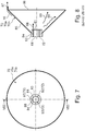
- the Figure 8 now shows schematically that the gas spreads in the direction of arrow 88 in the radial direction as a hydrogen flow, while the oxygen flow 89 is concentrated in a radially inner region.
- a split into the two gas flows 88 and 89 thus takes place in the area of the conical, bell-shaped vibration bodies 70a, 70b.
- a mixed gas stream is accordingly taken on different levels and at the same time a further gas component flows in the direction of arrow 46 over the tab 87 which is arranged at the edge and forms an annular gap in relation to the inner wall of the housing 44.
- the tab 87 and the radially outer flow gap 73 formed thereby can also be omitted.
- the separation of the radially inner gas streams 88, 89 is achieved by the different charging of the gas molecules, while the gas stream flowing outside in the circumferential area (direction of arrow 76) at the through-flow gap 73 consists of different mixed gas components.
- part of the gas flows over the outer circumference of the electrically positively charged anode shaft 68. This is shown in FIG Figure 7 shown, where it can be seen that there are recesses 82 between the round bars 72, through which the gas can flow along the surface of the positively charged anode shaft 68.
- the gas flows are further split into oxygen and hydrogen gas with the aid of oppositely charged electrically conductive disks, namely the cathode sheaths 69, which have a larger circumference and the anode disks 99, which have a smaller diameter.
- Such a differential voltage can be generated, for example, by a known electric pasture fence apparatus, such as that used in livestock farming for fencing cattle pastures.
- the pulse generator used here can be used with the same or modified pulse strength and the same or modified voltage difference as the known electric fence apparatus.
- anode and cathode plates 69, 99 are not only permanently or pulsed with direct current applied, but also individually dosed, for example with voltages in the range of 4, 8, 12V or 60, 120, 60V in any order, as well as pulse train and form.
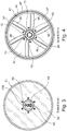
- bell-shaped resonance bodies 70a and 70b of the resonance device 70 form optional through-flow gaps 73 radially outwards in the direction of the inner wall of the housing, such through-flow gaps 73 are no longer necessary in the downstream anode and cathode disks 69, 99 because they have a large number of perforations for the gas passage have, as for example in Figure 5 is shown.
- the Figure 5 shows a plan view of the anode and cathode disks 69, 99, which are preferably arranged one inside the other in a vertical plane, each of the disks having a plurality of perforated bores 98 through which the gas flows.
- the holes 98 in the area of the cathode disk 69 and the anode disks 99 are dimensioned the same.
- the cathode disk is perforated with smaller bore diameters in the radially outer area and has larger throughflow windows in the radially inner area.
- the anode disk 99 is unaffected by this and has the previously mentioned holes 98.
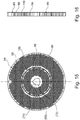
- Figures 15 and 16 show one opposite the Figure 5 modified embodiment in which the same parts are provided with the same reference numerals.
- the reference symbols in brackets show the positions in Figure 5 parts are positioned.
- the anode and cathode disks 69, 99 provided with the perforated bores 98 are joined into one another in a preferably vertical plane and can thus channel the gas flow even better and tap it in the extraction unit and also be more compact.
- the cathode voltage is applied to the outer section of the cathode disk 69 and the anode voltage to the inner section of the anode disk 99 closed insulating ring 109, preferably made of a ceramic material, electrically separated
- FIG. 2 the outlet end of the reactor vessel 44 is shown with a (in reality nonexistent) separating gap, which in practice forms a sealing surface 101 in the direction of a sealingly adjoining cover 102, in which an insulating block 71 for the one-sided, electrically insulated storage of the electrically charged anode shaft is arranged.
- a number of passage openings are provided in this cover 102, whereby it can be seen that the hydrogen gas flows radially outward in the direction of arrow 75 into a gas separator 47 connected to it, while the oxygen gas collects under the hydrogen gas and can thus be removed in separate chambers of the gas separator 47 .
- the hydrogen therefore collects in the hydrogen storage device 77 arranged above, while the oxygen collects in the oxygen storage device 78 arranged below.
- the oxygen can be withdrawn there via a withdrawal valve 50, while the hydrogen in the hydrogen storage device 77 can be withdrawn via a withdrawal valve and a feed line 51 arranged there.
- the process of dividing the gas flows into a hydrogen and oxygen flow 88, 89 can be further improved by arranging a semi-permeable membrane 80 in the area between the two gas reservoirs 77, 78, which separates the gas molecules of different sizes from one another.
- a drain hole 79 for condensed water can be arranged in the lower region of the gas separator 47, so that the condensed water can be fed to the water tank 17 in the direction of the arrow 22 via a return line 21.
- the resonance device 70 When the resonance device 70 is constructed with bell-shaped bodies 70a, 70b, cone walls 85 that engage in one another are preferred because a directed flow can be generated with such a large-area wall arrangement.
- the permanent magnets 59 are received in holders 92, the permanent magnets being arranged in recessed slots in the wall of the annular magnet sleeve 58.
- the magnetic ring sleeve 58 is made of a suitable coercive material.
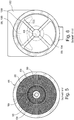
- the Figure 6 shows the section through the right-hand cover 102, where it can be seen that in the interior there is an insulating ring 100 with a number of spokes 103 arranged radially evenly distributed around the circumference, with a lower, approximately central one in the flow spaces separated from the spokes 103 according to the invention
- Oxygen region 104 forms for the separated oxygen flow 89, while a hydrogen cloud 105 with the separated hydrogen flow 88 is formed in the upper region of the cover.
- the advantage of the method according to the invention is that it is a continuous process because it is a serial sequence of different process stages according to FIG Figure 15 is, that is, it is an axially advancing gas flow that flows dynamically, while in the usual reactor vessels there is a static gas cloud that is conditioned.
- the invention has the advantage that a UV irradiation device 32 and an adjoining magnetizing device 34 use little energy to condition the water vapor flow, with small amounts of energy being required.
- the resonance device 39 arranged in the course of the flow picks up the natural resonance of the preconditioned water vapor and conditions it further with little expenditure of energy. The remaining energy is used to charge the capacitor plates, which requires considerably less energy than, for example, the known electrolysis processes or other comparable static processes. In this way, a higher gas yield can be achieved with lower energy input, which is based on a reactor vessel of the same volume.
- control parameters can be changed in the reactor cell 28, such as, for example, the frequency of the resonance device 39, the control voltage on the capacitor arrangement and the control voltage on the magnetization device 34.
- process parameters can also be changed within wide limits during the process in order to achieve an optimal process yield.
- a reactor cell 28 according to the invention with dimensions of approximately 500 mm in length and 250 mm in diameter and a weight of approximately 20 to 30 kg is capable of a gas flow of hydrogen and oxygen and / or Brown's gas in the range of 40 cbm / h. In this case, an electrical output of in the range from 60 to 100 kWh is required if no electricity-generating fuel cell 29 is used.
- These process parameters result in the particular suitability of such a device 1 for mobile use, in particular for the motor vehicle sector.
- such a gas generator is particularly suitable for all land, water and air vehicles.
Priority Applications (1)
| Application Number | Priority Date | Filing Date | Title |
|---|---|---|---|
| EP20157763.2A EP3865455A1 (fr) | 2020-02-17 | 2020-02-17 | Procédé et dispositif d'extraction des gaz de brown et/ou d'oxygène et d'hydrogène, en particulier pour moteurs à combustion, brûleurs chauffants ou piles à combustible |
Applications Claiming Priority (1)
| Application Number | Priority Date | Filing Date | Title |
|---|---|---|---|
| EP20157763.2A EP3865455A1 (fr) | 2020-02-17 | 2020-02-17 | Procédé et dispositif d'extraction des gaz de brown et/ou d'oxygène et d'hydrogène, en particulier pour moteurs à combustion, brûleurs chauffants ou piles à combustible |
Publications (1)
| Publication Number | Publication Date |
|---|---|
| EP3865455A1 true EP3865455A1 (fr) | 2021-08-18 |
Family
ID=69645898
Family Applications (1)
| Application Number | Title | Priority Date | Filing Date |
|---|---|---|---|
| EP20157763.2A Pending EP3865455A1 (fr) | 2020-02-17 | 2020-02-17 | Procédé et dispositif d'extraction des gaz de brown et/ou d'oxygène et d'hydrogène, en particulier pour moteurs à combustion, brûleurs chauffants ou piles à combustible |
Country Status (1)
| Country | Link |
|---|---|
| EP (1) | EP3865455A1 (fr) |
Cited By (1)
| Publication number | Priority date | Publication date | Assignee | Title |
|---|---|---|---|---|
| DE102021005168A1 (de) | 2021-10-15 | 2023-04-20 | Energy Cube GbR (vertretungsberechtigte Gesellschafter: Petra Rahlfs, 83022 Rosenheim, Roland Rieger, 75446 Wiernsheim) | Vorrichtung und Verfahren zur Stromerzeugung |
Citations (7)
| Publication number | Priority date | Publication date | Assignee | Title |
|---|---|---|---|---|
| US20040265137A1 (en) * | 2003-06-30 | 2004-12-30 | Ronny Bar-Gadda | Method for generating hydrogen from water or steam in a plasma |
| WO2005005009A2 (fr) * | 2003-06-30 | 2005-01-20 | Bar-Gadda, Llc. | Dissociation de l'eau moleculaire en hydrogene moleculaire |
| US20050178670A1 (en) * | 2001-06-18 | 2005-08-18 | Austin Gary N. | Transition structures and catalytic reaction pathways for the production of hydrogen and oxygen |
| DE102007026008A1 (de) * | 2007-06-04 | 2008-12-11 | Conpower Energieanlagen Gmbh & Co Kg. | Verfahren zur Wasserstoffgewinnung aus Dissoziation, sowie Dissoziationseinrichtung selbst |
| WO2011006749A1 (fr) * | 2009-07-14 | 2011-01-20 | Sonolis S.R.L. | Appareil pour la production d'hydrogène gazeux et système de production d'énergie utilisant un tel appareil |
| US9079772B2 (en) | 2003-08-01 | 2015-07-14 | Bar-Gadda Llc | Radiant energy dissociation of molecular water into molecular hydrogen |
| WO2019174659A1 (fr) | 2018-03-15 | 2019-09-19 | Karl Bau Gmbh | Procédé et ensemble servant à fabriquer de l'eau à teneur réduite en deutérium |
-
2020
- 2020-02-17 EP EP20157763.2A patent/EP3865455A1/fr active Pending
Patent Citations (8)
| Publication number | Priority date | Publication date | Assignee | Title |
|---|---|---|---|---|
| US20050178670A1 (en) * | 2001-06-18 | 2005-08-18 | Austin Gary N. | Transition structures and catalytic reaction pathways for the production of hydrogen and oxygen |
| US20040265137A1 (en) * | 2003-06-30 | 2004-12-30 | Ronny Bar-Gadda | Method for generating hydrogen from water or steam in a plasma |
| WO2005005009A2 (fr) * | 2003-06-30 | 2005-01-20 | Bar-Gadda, Llc. | Dissociation de l'eau moleculaire en hydrogene moleculaire |
| US7384619B2 (en) | 2003-06-30 | 2008-06-10 | Bar-Gadda, Llc | Method for generating hydrogen from water or steam in a plasma |
| US9079772B2 (en) | 2003-08-01 | 2015-07-14 | Bar-Gadda Llc | Radiant energy dissociation of molecular water into molecular hydrogen |
| DE102007026008A1 (de) * | 2007-06-04 | 2008-12-11 | Conpower Energieanlagen Gmbh & Co Kg. | Verfahren zur Wasserstoffgewinnung aus Dissoziation, sowie Dissoziationseinrichtung selbst |
| WO2011006749A1 (fr) * | 2009-07-14 | 2011-01-20 | Sonolis S.R.L. | Appareil pour la production d'hydrogène gazeux et système de production d'énergie utilisant un tel appareil |
| WO2019174659A1 (fr) | 2018-03-15 | 2019-09-19 | Karl Bau Gmbh | Procédé et ensemble servant à fabriquer de l'eau à teneur réduite en deutérium |
Cited By (1)
| Publication number | Priority date | Publication date | Assignee | Title |
|---|---|---|---|---|
| DE102021005168A1 (de) | 2021-10-15 | 2023-04-20 | Energy Cube GbR (vertretungsberechtigte Gesellschafter: Petra Rahlfs, 83022 Rosenheim, Roland Rieger, 75446 Wiernsheim) | Vorrichtung und Verfahren zur Stromerzeugung |
Similar Documents
| Publication | Publication Date | Title |
|---|---|---|
| AT508813B1 (de) | Elektrolytisches reaktionssystem zur erzeugung von gasförmigem wasserstoff und sauerstoff | |
| DE112009000305B4 (de) | Verfahren zur radialen Gegenstrom-Scher-Elektrolyse | |
| EP1875140B1 (fr) | Generateur de chaleur | |
| DE102007025551A1 (de) | Verfahren und Vorrichtung zur Verbrennung von kohlenwasserstoffhaltigen Brennstoffen | |
| DE2136265A1 (de) | Vorrichtung zum Reinigen der Abgase von Verbrennungsprozessen von Schadstoffen | |
| DE2109634A1 (de) | Verfahren und Lichtbogenheizeinrichtung zum Erhitzen von Gasen mittels·eines Lichtbogens | |
| EP3865455A1 (fr) | Procédé et dispositif d'extraction des gaz de brown et/ou d'oxygène et d'hydrogène, en particulier pour moteurs à combustion, brûleurs chauffants ou piles à combustible | |
| EP1685276B1 (fr) | Dispositif de conversion d'energie | |
| DE2107834A1 (de) | Lichtbogenheizeinrichtung | |
| EP3393624B1 (fr) | Procédé et dispositif servant au dégazage sélectif du méthane d'un liquide de lavage | |
| EP3529481B1 (fr) | Procédé de commande d'un groupe motopropulseur avec haute efficacité et groupe motopropulseur | |
| DE1464037A1 (de) | Verfahren und Vorrichtung zur Speisung eines elektro-thermischen Strahlentriebs mit Vortriebsmitteln | |
| WO2011050789A2 (fr) | Petite centrale et procédé et dispositif pour récupérer de l'hydrogène de grande pureté | |
| EP4103765B1 (fr) | Système réactionnel électrolytique pour la production d'hydrogène et d'oxygène sous forme gazeuse | |
| DE102013109778A1 (de) | Verfahren und Vorrichtung zur kontinuierlichen Wiederaufbereitung von Abgas eines Fusionsreaktors | |
| DE1539302A1 (de) | Energieumwandlungsvorrichtung | |
| DE102004017975A1 (de) | Verfahren und Vorrichtung zum Aufschluss von organischem Material in einem fließfähigen Stoffsystem | |
| DE2733444A1 (de) | Magnetodynamische autoelektrolyse | |
| DE10033969B4 (de) | Vorrichtung zur Erzeugung von Kollisionen gegenläufiger Ionenbündel | |
| DE1144238B (de) | Vorrichtung zur kontinuierlichen Durchfuehrung chemischer Reaktionen in der Glimmentladung | |
| DE3025500A1 (de) | Verfahren und vorrichtung zur intensivierung von verbrennungsvorgaengen in verbrennungsmaschinen und verbrennungsanlagen | |
| WO2012146781A2 (fr) | Procédé pour générer de l'énergie électrique, cinétique et thermique à partir de mélanges air-eau ainsi que pour séparer les éléments constitutifs moléculaires | |
| WO2023179815A1 (fr) | Appareil et procede pour séparer des substances | |
| DE3642200A1 (de) | Verfahren und vorrichtung zum erzeugen mechanischer energie | |
| DE102015102998A1 (de) | Verfahren und Anordnung zur Durchführung des Verfahrens zum elektrochemischen Verbinden von Wasserstoff und der Sauerstoff als Elektrolysegas mit zumindest einem an sich bekannten Brenngas als Trägergas zu einem verbundenen Gas |
Legal Events
| Date | Code | Title | Description |
|---|---|---|---|
| PUAI | Public reference made under article 153(3) epc to a published international application that has entered the european phase |
Free format text: ORIGINAL CODE: 0009012 |
|
| STAA | Information on the status of an ep patent application or granted ep patent |
Free format text: STATUS: THE APPLICATION HAS BEEN PUBLISHED |
|
| AK | Designated contracting states |
Kind code of ref document: A1 Designated state(s): AL AT BE BG CH CY CZ DE DK EE ES FI FR GB GR HR HU IE IS IT LI LT LU LV MC MK MT NL NO PL PT RO RS SE SI SK SM TR |
|
| STAA | Information on the status of an ep patent application or granted ep patent |
Free format text: STATUS: REQUEST FOR EXAMINATION WAS MADE |
|
| 17P | Request for examination filed |
Effective date: 20211207 |
|
| RBV | Designated contracting states (corrected) |
Designated state(s): AL AT BE BG CH CY CZ DE DK EE ES FI FR GB GR HR HU IE IS IT LI LT LU LV MC MK MT NL NO PL PT RO RS SE SI SK SM TR |
|
| STAA | Information on the status of an ep patent application or granted ep patent |
Free format text: STATUS: EXAMINATION IS IN PROGRESS |
|
| 17Q | First examination report despatched |
Effective date: 20231025 |