EP3865455A1 - Method and device for obtaining browns gas and / or oxygen and hydrogen, especially for combustion engines, heating burners or fuel cells - Google Patents
Method and device for obtaining browns gas and / or oxygen and hydrogen, especially for combustion engines, heating burners or fuel cells Download PDFInfo
- Publication number
- EP3865455A1 EP3865455A1 EP20157763.2A EP20157763A EP3865455A1 EP 3865455 A1 EP3865455 A1 EP 3865455A1 EP 20157763 A EP20157763 A EP 20157763A EP 3865455 A1 EP3865455 A1 EP 3865455A1
- Authority
- EP
- European Patent Office
- Prior art keywords
- gas
- water
- hydrogen
- plasma
- oxygen
- Prior art date
- Legal status (The legal status is an assumption and is not a legal conclusion. Google has not performed a legal analysis and makes no representation as to the accuracy of the status listed.)
- Pending
Links
- 239000007789 gas Substances 0.000 title claims abstract description 157
- 238000000034 method Methods 0.000 title claims abstract description 98
- 229910052739 hydrogen Inorganic materials 0.000 title claims abstract description 59
- 239000001257 hydrogen Substances 0.000 title claims abstract description 59
- 239000001301 oxygen Substances 0.000 title claims abstract description 51
- 229910052760 oxygen Inorganic materials 0.000 title claims abstract description 51
- QVGXLLKOCUKJST-UHFFFAOYSA-N atomic oxygen Chemical compound [O] QVGXLLKOCUKJST-UHFFFAOYSA-N 0.000 title claims abstract description 50
- 238000002485 combustion reaction Methods 0.000 title claims abstract description 35
- 239000000446 fuel Substances 0.000 title claims abstract description 19
- 238000010438 heat treatment Methods 0.000 title description 3
- 125000004435 hydrogen atom Chemical class [H]* 0.000 title 1
- XLYOFNOQVPJJNP-UHFFFAOYSA-N water Substances O XLYOFNOQVPJJNP-UHFFFAOYSA-N 0.000 claims abstract description 115
- UFHFLCQGNIYNRP-UHFFFAOYSA-N Hydrogen Chemical compound [H][H] UFHFLCQGNIYNRP-UHFFFAOYSA-N 0.000 claims abstract description 71
- 230000008569 process Effects 0.000 claims abstract description 59
- 230000005284 excitation Effects 0.000 claims abstract description 25
- 238000004519 manufacturing process Methods 0.000 claims abstract description 15
- 238000000926 separation method Methods 0.000 claims abstract description 12
- 150000002431 hydrogen Chemical class 0.000 claims abstract 5
- 238000002347 injection Methods 0.000 claims description 33
- 239000007924 injection Substances 0.000 claims description 33
- 230000005415 magnetization Effects 0.000 claims description 27
- 238000006243 chemical reaction Methods 0.000 claims description 22
- 230000005684 electric field Effects 0.000 claims description 15
- 230000015572 biosynthetic process Effects 0.000 claims description 6
- 230000015556 catabolic process Effects 0.000 claims description 5
- 239000002131 composite material Substances 0.000 claims description 3
- 239000000203 mixture Substances 0.000 claims description 3
- 230000004992 fission Effects 0.000 claims 1
- 210000004027 cell Anatomy 0.000 description 45
- 210000002381 plasma Anatomy 0.000 description 32
- 239000003595 mist Substances 0.000 description 15
- 230000008901 benefit Effects 0.000 description 9
- 238000005868 electrolysis reaction Methods 0.000 description 9
- 238000000605 extraction Methods 0.000 description 9
- 239000003990 capacitor Substances 0.000 description 8
- 230000003068 static effect Effects 0.000 description 8
- 239000003570 air Substances 0.000 description 7
- 238000003860 storage Methods 0.000 description 7
- 238000009281 ultraviolet germicidal irradiation Methods 0.000 description 7
- 239000007788 liquid Substances 0.000 description 6
- MYMOFIZGZYHOMD-UHFFFAOYSA-N Dioxygen Chemical compound O=O MYMOFIZGZYHOMD-UHFFFAOYSA-N 0.000 description 5
- 239000003054 catalyst Substances 0.000 description 5
- 238000012545 processing Methods 0.000 description 5
- 230000001143 conditioned effect Effects 0.000 description 4
- 238000009833 condensation Methods 0.000 description 3
- 230000005494 condensation Effects 0.000 description 3
- 229910001882 dioxygen Inorganic materials 0.000 description 3
- 238000005192 partition Methods 0.000 description 3
- 238000007789 sealing Methods 0.000 description 3
- 239000000243 solution Substances 0.000 description 3
- 238000000889 atomisation Methods 0.000 description 2
- 150000001875 compounds Chemical class 0.000 description 2
- 238000013461 design Methods 0.000 description 2
- 239000003792 electrolyte Substances 0.000 description 2
- 230000005686 electrostatic field Effects 0.000 description 2
- 239000013505 freshwater Substances 0.000 description 2
- 239000000463 material Substances 0.000 description 2
- 239000012528 membrane Substances 0.000 description 2
- 239000002184 metal Substances 0.000 description 2
- 230000000116 mitigating effect Effects 0.000 description 2
- 238000006386 neutralization reaction Methods 0.000 description 2
- 241000283690 Bos taurus Species 0.000 description 1
- YZCKVEUIGOORGS-OUBTZVSYSA-N Deuterium Chemical compound [2H] YZCKVEUIGOORGS-OUBTZVSYSA-N 0.000 description 1
- 230000001154 acute effect Effects 0.000 description 1
- 238000004220 aggregation Methods 0.000 description 1
- 230000002776 aggregation Effects 0.000 description 1
- 239000012080 ambient air Substances 0.000 description 1
- 230000009286 beneficial effect Effects 0.000 description 1
- 239000003462 bioceramic Substances 0.000 description 1
- 229910010293 ceramic material Inorganic materials 0.000 description 1
- 238000005352 clarification Methods 0.000 description 1
- 230000000295 complement effect Effects 0.000 description 1
- 238000010924 continuous production Methods 0.000 description 1
- 238000001816 cooling Methods 0.000 description 1
- 230000008878 coupling Effects 0.000 description 1
- 238000010168 coupling process Methods 0.000 description 1
- 238000005859 coupling reaction Methods 0.000 description 1
- 238000000354 decomposition reaction Methods 0.000 description 1
- 238000010612 desalination reaction Methods 0.000 description 1
- 229910052805 deuterium Inorganic materials 0.000 description 1
- 239000002283 diesel fuel Substances 0.000 description 1
- 239000012153 distilled water Substances 0.000 description 1
- 238000005553 drilling Methods 0.000 description 1
- 230000000694 effects Effects 0.000 description 1
- 230000005611 electricity Effects 0.000 description 1
- 238000005265 energy consumption Methods 0.000 description 1
- 238000005516 engineering process Methods 0.000 description 1
- 230000003203 everyday effect Effects 0.000 description 1
- 238000002474 experimental method Methods 0.000 description 1
- 238000011049 filling Methods 0.000 description 1
- 238000010304 firing Methods 0.000 description 1
- 230000004907 flux Effects 0.000 description 1
- 239000002803 fossil fuel Substances 0.000 description 1
- 239000002737 fuel gas Substances 0.000 description 1
- 239000003502 gasoline Substances 0.000 description 1
- 230000005484 gravity Effects 0.000 description 1
- 239000010797 grey water Substances 0.000 description 1
- 238000009434 installation Methods 0.000 description 1
- 238000009413 insulation Methods 0.000 description 1
- 238000012423 maintenance Methods 0.000 description 1
- 229910044991 metal oxide Inorganic materials 0.000 description 1
- 150000004706 metal oxides Chemical class 0.000 description 1
- 238000002156 mixing Methods 0.000 description 1
- 238000012986 modification Methods 0.000 description 1
- 230000004048 modification Effects 0.000 description 1
- 125000004430 oxygen atom Chemical group O* 0.000 description 1
- 239000002245 particle Substances 0.000 description 1
- 238000009304 pastoral farming Methods 0.000 description 1
- 150000003839 salts Chemical class 0.000 description 1
- 239000010865 sewage Substances 0.000 description 1
- 239000002352 surface water Substances 0.000 description 1
- 238000012360 testing method Methods 0.000 description 1
- 238000012546 transfer Methods 0.000 description 1
- 230000001960 triggered effect Effects 0.000 description 1
- 238000002604 ultrasonography Methods 0.000 description 1
- 238000005303 weighing Methods 0.000 description 1
- 238000003466 welding Methods 0.000 description 1
- 239000002349 well water Substances 0.000 description 1
- 235000020681 well water Nutrition 0.000 description 1
Images


Classifications
-
- C—CHEMISTRY; METALLURGY
- C01—INORGANIC CHEMISTRY
- C01B—NON-METALLIC ELEMENTS; COMPOUNDS THEREOF; METALLOIDS OR COMPOUNDS THEREOF NOT COVERED BY SUBCLASS C01C
- C01B3/00—Hydrogen; Gaseous mixtures containing hydrogen; Separation of hydrogen from mixtures containing it; Purification of hydrogen
- C01B3/02—Production of hydrogen or of gaseous mixtures containing a substantial proportion of hydrogen
- C01B3/04—Production of hydrogen or of gaseous mixtures containing a substantial proportion of hydrogen by decomposition of inorganic compounds, e.g. ammonia
- C01B3/042—Decomposition of water
-
- C—CHEMISTRY; METALLURGY
- C01—INORGANIC CHEMISTRY
- C01B—NON-METALLIC ELEMENTS; COMPOUNDS THEREOF; METALLOIDS OR COMPOUNDS THEREOF NOT COVERED BY SUBCLASS C01C
- C01B13/00—Oxygen; Ozone; Oxides or hydroxides in general
- C01B13/02—Preparation of oxygen
- C01B13/0203—Preparation of oxygen from inorganic compounds
- C01B13/0207—Water
-
- F—MECHANICAL ENGINEERING; LIGHTING; HEATING; WEAPONS; BLASTING
- F02—COMBUSTION ENGINES; HOT-GAS OR COMBUSTION-PRODUCT ENGINE PLANTS
- F02B—INTERNAL-COMBUSTION PISTON ENGINES; COMBUSTION ENGINES IN GENERAL
- F02B43/00—Engines characterised by operating on gaseous fuels; Plants including such engines
-
- F—MECHANICAL ENGINEERING; LIGHTING; HEATING; WEAPONS; BLASTING
- F02—COMBUSTION ENGINES; HOT-GAS OR COMBUSTION-PRODUCT ENGINE PLANTS
- F02M—SUPPLYING COMBUSTION ENGINES IN GENERAL WITH COMBUSTIBLE MIXTURES OR CONSTITUENTS THEREOF
- F02M21/00—Apparatus for supplying engines with non-liquid fuels, e.g. gaseous fuels stored in liquid form
- F02M21/02—Apparatus for supplying engines with non-liquid fuels, e.g. gaseous fuels stored in liquid form for gaseous fuels
- F02M21/0203—Apparatus for supplying engines with non-liquid fuels, e.g. gaseous fuels stored in liquid form for gaseous fuels characterised by the type of gaseous fuel
- F02M21/0206—Non-hydrocarbon fuels, e.g. hydrogen, ammonia or carbon monoxide
-
- F—MECHANICAL ENGINEERING; LIGHTING; HEATING; WEAPONS; BLASTING
- F02—COMBUSTION ENGINES; HOT-GAS OR COMBUSTION-PRODUCT ENGINE PLANTS
- F02M—SUPPLYING COMBUSTION ENGINES IN GENERAL WITH COMBUSTIBLE MIXTURES OR CONSTITUENTS THEREOF
- F02M25/00—Engine-pertinent apparatus for adding non-fuel substances or small quantities of secondary fuel to combustion-air, main fuel or fuel-air mixture
- F02M25/022—Adding fuel and water emulsion, water or steam
- F02M25/025—Adding water
-
- Y—GENERAL TAGGING OF NEW TECHNOLOGICAL DEVELOPMENTS; GENERAL TAGGING OF CROSS-SECTIONAL TECHNOLOGIES SPANNING OVER SEVERAL SECTIONS OF THE IPC; TECHNICAL SUBJECTS COVERED BY FORMER USPC CROSS-REFERENCE ART COLLECTIONS [XRACs] AND DIGESTS
- Y02—TECHNOLOGIES OR APPLICATIONS FOR MITIGATION OR ADAPTATION AGAINST CLIMATE CHANGE
- Y02E—REDUCTION OF GREENHOUSE GAS [GHG] EMISSIONS, RELATED TO ENERGY GENERATION, TRANSMISSION OR DISTRIBUTION
- Y02E60/00—Enabling technologies; Technologies with a potential or indirect contribution to GHG emissions mitigation
- Y02E60/30—Hydrogen technology
- Y02E60/36—Hydrogen production from non-carbon containing sources, e.g. by water electrolysis
-
- Y—GENERAL TAGGING OF NEW TECHNOLOGICAL DEVELOPMENTS; GENERAL TAGGING OF CROSS-SECTIONAL TECHNOLOGIES SPANNING OVER SEVERAL SECTIONS OF THE IPC; TECHNICAL SUBJECTS COVERED BY FORMER USPC CROSS-REFERENCE ART COLLECTIONS [XRACs] AND DIGESTS
- Y02—TECHNOLOGIES OR APPLICATIONS FOR MITIGATION OR ADAPTATION AGAINST CLIMATE CHANGE
- Y02T—CLIMATE CHANGE MITIGATION TECHNOLOGIES RELATED TO TRANSPORTATION
- Y02T10/00—Road transport of goods or passengers
- Y02T10/10—Internal combustion engine [ICE] based vehicles
- Y02T10/12—Improving ICE efficiencies
-
- Y—GENERAL TAGGING OF NEW TECHNOLOGICAL DEVELOPMENTS; GENERAL TAGGING OF CROSS-SECTIONAL TECHNOLOGIES SPANNING OVER SEVERAL SECTIONS OF THE IPC; TECHNICAL SUBJECTS COVERED BY FORMER USPC CROSS-REFERENCE ART COLLECTIONS [XRACs] AND DIGESTS
- Y02—TECHNOLOGIES OR APPLICATIONS FOR MITIGATION OR ADAPTATION AGAINST CLIMATE CHANGE
- Y02T—CLIMATE CHANGE MITIGATION TECHNOLOGIES RELATED TO TRANSPORTATION
- Y02T10/00—Road transport of goods or passengers
- Y02T10/10—Internal combustion engine [ICE] based vehicles
- Y02T10/30—Use of alternative fuels, e.g. biofuels
Definitions
- the subject matter of the invention is a method and a device for the production of Browns gas and / or oxygen and hydrogen according to the preamble of claim 1.
- HHO cells can be set up as wet cells and dry cells.
- the electrodes In a wet cell, the electrodes are located in a vessel and are completely surrounded by water. The vessel is built gas-tight so that the gas can flow into the gas hose.
- the structure of the dry cell is completely different. No vessel is used there, but the electrodes themselves form a vessel so that the cell remains dry on the outside. While a wet cell, like a tub, holds the water for electrolysis, a dry cell has to provide for an inflow of water, because the dry cell would be without a constant water inflow "dry out" very quickly and overheat.
- the water inlet is provided by a water tank that must be installed above the dry cell so that the water can flow into the cell under the force of gravity. In every type of cell, the anode and cathode are always close to each other (usually 1.5 mm - 3 mm).
- the electrodes are provided with holes or slits at the top and bottom so that the water can run through the entire cell at the bottom and the gas can escape at the top.
- the electrodes are kept at a distance from one another with a rubber seal in the form of a ring. Electrodes and rubber rings thus form the vessel of the dry cell in which the water is electrolyzed.
- Each dry cell has a water inlet (below) and a gas outlet (above).
- the cell and water tank thus form a cycle. Water constantly flows from the tank into the cell and gas, mixed with water, runs back into the tank. This circuit is not only used for the supply of water, but also for cooling.
- a cell consists of a stack of plates of electrodes that are connected to the vehicle's electrical system (12 or 24 volts).
- a feeder supplies water while the electrolysis gas (oxyhydrogen, consisting of hydrogen and oxygen) is collected together [end of quote].
- WO 2019174659A1 a method and an arrangement for producing deuterium-reduced water has become known, which is characterized in that the HHO gas obtained from electrolysis is injected into a reactor and ignited and in the presence of a catalyst made of metal oxides at temperatures from 2,800 ° C to 3,500 ° C is converted into water of reaction in a plasma, with air being fed to the combustion furnace, the air surrounding the plasma and thus the plasma being cooled and then the plasma being discharged as exhaust air after the combustion.
- One such method is to obtain water from an HHO gas.
- the disadvantage of this known method is that the opposite route is taken compared to the invention, namely that it shows how water is recovered from a plasma.
- the formation of a high-temperature plasma in a range from 2,800 ° C. to 3,500 ° C. is undesirable and increases the costs of such a known reactor.
- This known method also has a disadvantage that high process temperatures are required for the production of a plasma and there is also the need to use catalysts for the plasma processing, which increases the production costs and the maintenance of such a system.
- Both of these plants are not able to be used as small transportable reactors, for example for the production of Browns gas and / or oxygen and hydrogen in motor vehicles or other mobile plants.
- the energy given off in the radial direction inwards by the reactor is absorbed by the water molecules and it is split into hydrogen and oxygen.
- the disadvantage of this known device is also the high energy consumption, the high process temperatures and the lack of applicability for everyday use.
- the invention is therefore based on the object of developing a method and a device for the production of Browns gas and / or oxygen and hydrogen in such a way that an easy-to-use, relatively inexpensive to manufacture system is achieved in which it is possible to use relatively small Use of energy to enable a large yield of Browns gas and / or hydrogen.
- the process for generating hydrogen and oxygen and / or Brown's gas from water is a physical splitting process using a sequence of different excitation processes in HHO with subsequent separation of the gases H2 and O2.
- the invention relates to a method for generating hydrogen / Browns gas from water, in which the water runs through a dynamic process and is exposed to various excitation methods. Electrolytes or catalysts are not required in the process, but could be beneficial.
- the water is injected into a reactor according to a first process variant with an injection nozzle, which at the beginning of the process is depressurized compared to the ambient air.
- water is fed into the reactor without the use of an injection pump.
- the water is first put into circulation in a circuit using a pump.
- the water is first ionized, aligned by permanent magnets or magnetic coils, and made to vibrate with a radio signal at a certain frequency and thus reaches a plasma state.
- the water passes specially shaped and arranged electrodes to which specific voltages are applied permanently and / or in a pulsed manner, as a result of which a subset of hydrogen and oxygen are separated.
- the non-split fraction of the water remains in circulation and continuously reaches higher levels of excitement, which increases the efficiency.
- Fresh water can be supplied permanently.
- the advantage of the invention is to design a method of the type mentioned at the beginning for the production of hydrogen / Brown's gas in such a way that it can be implemented at the same time as cost-effectively and ecologically compatible as possible. There is a requirement to obtain a larger volume of hydrogen gas with the same amount of energy as is used in electrolysis processes.
- the design of the method should be applicable both stationary and mobile.
- an essential part of the invention is dynamic scalability.
- control parameters such as volume flow, frequency, magnet strength and voltage, the amount of gases generated can be dynamically adjusted during operation. This allows a dosed, needs-based supply of specific gas quantities for requirements in mobile applications in vehicle dynamics or in the process flow in industrial applications.
- Another object of the invention is to provide a device for carrying out such a method.
- the process primarily has the advantage of avoiding the known wet cell electrolysis process by replacing the known static process with a dynamic process.
- the volume flow of the water is not only passed through metal plates with an electrical charge with low dynamics, but is sometimes conducted several times through the reactor in a faster hydraulic and / or pneumatic flow.
- the water When passing through the reactor, the water is first ionized. Depending on the application, this can be achieved by certain permanent magnets and electromagnets, by UV light, by applying a direct voltage or passing through a bioceramic filter.
- the water is excited in pulses with a radio frequency inside the reactor and is thus at least partially converted into a plasma state.
- the water in the mixed state of aggregation is passed over an arrangement of electrodes which are arranged transversely to the direction of flow and are equipped with sufficient reaction surfaces in the direction of flow and which are permanently and / or pulsed with a fixed, higher pulse and / or DC voltage .
- electrodes which are arranged transversely to the direction of flow and are equipped with sufficient reaction surfaces in the direction of flow and which are permanently and / or pulsed with a fixed, higher pulse and / or DC voltage .
- the water flow generated during the feed or the water mist produced during injection is kept in circulation while the dissolved gas is separated upwards.
- the gas is fed as brown gas through one or more gas washers (bubblers), particle filters and non-return valves for direct use or divided into H2 and O2 in a gas separator and thus fed to use or storage.
- gas washers bubblers
- particle filters particle filters
- non-return valves for direct use or divided into H2 and O2 in a gas separator and thus fed to use or storage.
- the process is suitable both for fresh water in different qualities (rainwater, surface water, well water, condensation water, distilled water, gray water from sewage processes, etc.), as well as for salt water without prior desalination.
- the gas obtained in this way can be used as a fuel, just like conventionally produced hydrogen or Brown's gas, e.g. for welding equipment, industrial firing, heating systems, etc. can be used. It can be used for exhaust gas neutralization in combustion engines and thermal systems in the process or downstream for exhaust gas neutralization. In the transport sector, this technology can be used to implement hydrogen filling stations without tank farms, which generate the gas in needs-based portions.
- hydrogen or Brown's Gas can be generated for vehicles on land, water and air according to the current requirements of the driving dynamics. It is not necessary to store gas in the vehicle. The conversion into kinetic or electrical energy can be done by internal combustion engines as well as by fuel cells.
- a fifth stage is provided for this case, in which the gas flow is split into hydrogen and oxygen in the area of an electric field with a pulse voltage or a direct voltage.
- the HHO mixed gas is already tapped off at the exit of the fourth stage in order to feed the Brown's gas obtained for further processing.
- the two gas flows separated in this way can be fed in a sixth stage to a consumer, which is, for example, a fuel cell, an internal combustion engine, an exhaust gas mitigation or another industrial process .
- magnetization with a swirl takes place in the third stage, then such magnetization can be achieved with various device features.
- the magnetization is preferably carried out with the aid of permanent magnets, which are arranged distributed uniformly on the circumference of a magnetic ring socket.
- the fourth stage which is aimed at resonance excitation, should preferably take place with frequency excitation in the microwave range.
- a suitable frequency generator is required for this, which operates, for example, in the frequency range 100 to 200 MHz.
- a frequency range in the range from 124 to 132 MHz is preferred here.
- microwave exciters are of course also possible, such as infrasound or ultrasonic resonance excitation.
- the resonance excitation is followed by a fifth stage with the generation of an electric field.
- a device is described as it is preferably provided for the production of Brown's gas and / or hydrogen and oxygen for the fuel supply of an internal combustion engine.
- Such an internal combustion engine can be a reciprocating piston engine, a rotary piston engine or another suitable engine which is suitable for generating mechanical energy on an output shaft (crankshaft) via a combustion process.
- a closed circuit for the fuel supply of an internal combustion engine in which water in liquid form and, at the same time, a hydrogen gas obtained from the reactor are injected into the combustion chambers of the internal combustion engine.
- Such a device can also be used for stationary internal combustion engines, such as those used as a combined heat and power unit in the basement of residential buildings.
- a closed circuit which, starting from liquid water which is available in a water tank, adds a certain amount to the The inlet side of a reactor cell is injected or allowed to flow in and then the previously mentioned process stages run one after the other.
- the reactor cell consists of a pressure-resistant metal housing closed on the inlet side, on the inlet side of which a water stream now flows in via an injection nozzle or an inlet valve and / or a water jet is injected. This is followed by ionization as part of the second process stage.
- the water molecules are ionized and aligned, so that a certain oriented molecular compound results, which is subjected to magnetization in the third stage, which preferably generates an additional spiral vortex, which is directed around the longitudinally directed flow axis.
- the aligned water molecules are converted into a plasma. This aligns the flow of molecules in a certain axial direction, so that the energy of the water molecules generates an energy input and improves the formation of a plasma.
- the magnetization takes place with permanent magnets, i.e. it is a static magnetic field, while in a second, alternative embodiment it is provided that a polarized magnetic field is used, which achieves a pulsed magnetization with the aid of magnetic coils.
- the pulse frequency in this second exemplary embodiment is in the range between 0.01 Hz to 10 Hz.
- the plasma flow thus formed in the magnetization stage is preferably a spiral current that flows in the axial direction of the Reactor shows a certain turbulence structure. The plasma flow swirled in this way is now brought into the range of a resonance device.
- This resonance device preferably consists of at least two bell-shaped, mutually spaced and insulated bell-shaped bodies, which are electrically conductive, with a microwave frequency being applied between the two bell-shaped bodies, which is in the range of the above-mentioned frequency band.
- a high-frequency microwave resonance field is generated in the space between the two conductive, bell-shaped bodies, the frequency of which is tuned so that it matches the frequency of the molecular structure of the plasma formed.
- the majority of the molecules formed should then disintegrate or "stretch out” into Brown's gas, i.e. there is a loose molecular compound or even a separation of the molecules.
- this fourth stage (resonance excitation) there is already a gas breakdown into a mixed gas consisting of oxygen and hydrogen or optionally a mixed gas consisting of Browns gas HHO.
- the Browns gas can already be tapped and sent for further processing.
- This electric field consists of capacitor plates arranged alternately polarized in the axial direction, which are designed as straight, perforated disks and when passing through the alternately polarized electrostatic field formed between the disks, the mixed gas breaks down into the individual gases hydrogen and oxygen.
- oxygen and hydrogen can be withdrawn separately and optionally one or both gases be fed to a consumer, such as a fuel cell, an internal combustion engine, an exhaust gas mitigation, or another industrial process, in particular also a block-type thermal power station.
- a consumer such as a fuel cell, an internal combustion engine, an exhaust gas mitigation, or another industrial process, in particular also a block-type thermal power station.
- a cycle of the method according to the invention is shown by way of example, a device 1 for gas extraction being shown by way of example which generates oxygen and hydrogen gas, the hydrogen gas preferably being fed to an internal combustion engine 2 which, in the exemplary embodiment shown, is designed as a reciprocating piston engine.
- the invention is not restricted to this. Any gas consumer can be used, as mentioned in the description mentioned at the beginning.
- a rotary piston engine or another internal combustion engine can therefore also be used, for example gas engines designed for biogas plants.
- a fuel cell can also be used.
- the example of the internal combustion engine 2 shown here shows that it has a number of cylinder rows 3, 4 in V-shape, the valves in the combustion chambers being controlled by a camshaft 5 which is driven by a crankshaft 6 via a drive belt 7 .
- the device 1 for gas extraction consists partly of an injection device with which the water is injected from a water tank 17 via a feed valve 20 and an injection pump 18 under pressure in the direction of the arrow 10 into the two parallel connection lines 16 on the cylinder head 13, 14 .
- the hydrogen gas returned from the process is injected into the combustion chamber via a feed line 11 and via the feed line connections 11a and 11b parallel to the connections 15 and 16.
- connection 15 there is preferably an injection of the fuel gas into the combustion chamber controlled by the engine cycle for feeding in the hydrogen gas via the connections 11a, 11b.
- the hydrogen gas is conveyed in the direction of arrow 12 from the feed line 11 under a certain overpressure into the feed lines 11a, 11b and there it is injected into the combustion chamber in cycles.
- (liquid) water is injected from the water tank 17 via the feed valve 20 and an injection pump 18 arranged on it via an injection nozzle located in the branch line 19 into the inlet area of the reactor cell 28.
- a fourth embodiment, as in Fig. 18 shows a vertical layout of the reactor, the injection nozzle being arranged directly at the entrance of the interior of the swirl chamber 62 and introducing the previously ionized and magnetized still liquid water directly into the resonance device in a nebulized form, the mist spontaneously changing to the plasma state.
- the injection device 31 is thus directed into the interior 45 of the reactor cell 28 and the water flow and / or water mist prepared in this way is now processed in stages, as shown in FIG Figure 15 is shown in the schematic process flow.
- the water mist first reaches the area of an ionization stage, which is preferably designed as UV irradiation 32 and which has a ring-shaped, UV light flux 33 directed radially from the outside inwards is generated, which penetrates and radiates through the water mist and thus lead to an initial alignment of the dipole-like water molecules.
- an ionization stage which is preferably designed as UV irradiation 32 and which has a ring-shaped, UV light flux 33 directed radially from the outside inwards is generated, which penetrates and radiates through the water mist and thus lead to an initial alignment of the dipole-like water molecules.
- the water molecules are also ionized at the same time, which means that the water molecules become conductive and more easily submit to the magnetization arranged there in the reaction space 55 in the subsequent third stage.
- the magnetization takes place - as shown schematically - by a magnetization device 34 which generates a suitable magnetic field 35 in the reaction space and thus also flows through the conditioned water mist.
- the gas already breaks down into the gas components oxygen and hydrogen and at this point a mixed gas could already be tapped as Brown's gas HHO.
- a control computer 27 is preferably used, which has a number of control lines 23, 24; 36-38; 43 has.
- the feed valve 20 is controlled via the signal line 23 and the injection pump 18 via the control line 24.
- the injection nozzle 26 is controlled via the control line 25.
- the hydrogen obtained can also be used to supply a fuel cell 29 with energy, which in turn generates electricity which, via the power supply 30, supplies the control computer 27 on the one hand and all other components of the reactor cell 28 on the other.
- the fuel cell 29 can also be omitted and an external power supply can be provided instead.
- the entire device 1 for gas extraction can even be operated independently of the power supply.
- control lines 36, 37, 38 which control the individual electrical components, as is shown in the schematic exemplary embodiment Figure 1 is shown.
- the control line 36 is used, for example, to control the magnet device 34 if it consists of electrically controllable coils.
- the control line 37 serves to control the UV irradiation 32, the control line 38 to control the resonance device 39 consisting of the cathode disks 69 and the anode disks 99.
- the injection takes place in the area of an end cover 52 which closes off the reactor vessel 44 from the end in a pressure-tight manner.
- a nozzle arrangement 53 is arranged in the cover 52 and consists on the one hand of the injection nozzle 26 and on the other hand of a nozzle for the introduction of the recirculated gas via the circulation line 106.
- the Figure 10 shows the front view of the cover 52 with the screw plugs 94 for the front-side closure of the reactor cell 28.
- the injection can take place directly into the swirl chamber 62.
- the injection nozzle 53 is arranged in the partition 61 between the magnetization stage 55 and the reaction chamber 67.
- the pressure is already applied to the cover 52.
- the liquid water in the reaction space (for 32) is subjected to ionization and in the reaction space (for 34) magnetization takes place under pressure with simultaneous ionization and magnetization. In this state, atomization takes place in the reaction chamber, as a result of which the water mist changes into the plasma state.
- a partition wall 61 is arranged at the output of the magnetization stage, which in Figure 3 is shown in section. It can be seen there that the partition itself is impermeable to gas and a gas flow occurs only in an inner annular space 64, the inlet-side injection nozzle 26 being shown with the reference numeral 53 and the inlet-side gas recirculation with 53a.
- the water mist formed in this way is blown into the reaction space 54 and flows in the axial direction (arrow direction 31a) through a UV irradiation device 32, which in the embodiment shown consists of an LED chain 56 which is arranged all around in the wall area of a transparent sleeve 91. This is in Figure 9 shown.
- the transparent sleeve 31, on the circumference of which the LED chain 56 is arranged, is thus fitted in the housing 57 in a sealed manner.
- the magnetizing device 34 is in the Figures 2 , 10, 11 as well as in the Figures 12 to 14 shown. It essentially consists of a magnetic ring bushing 58, in the outer surface of which a number of permanent magnets 59 are arranged evenly distributed around the circumference, which are arranged in a stepwise offset from one another on a spiral line on the case of the housing of the magnetic ring bushing 58, as exemplified in FIG Figure 11 is shown.
- the center line through the permanent magnets 59 arranged in the circumferential direction is denoted by the respective oblique line 93, so that a spiral flow 60 according to FIG Figure 9 results.
- the water molecules are aligned, with the hydrogen molecules flying ahead in the direction of flow (axial direction of the reactor cell 28) compared to the oxygen molecules, which are slower in comparison.
- the ionization also acts in the form of vibrations influencing the water mist, as does the downstream magnetizing device 34. This induces an increased level of excitation on the water molecules, which leads to plasma formation and subsequent splitting.
- the flow guide device 61 consists of a number of inclined guide surfaces 96 which are arranged uniformly distributed around the circumference and form a reaction chamber 67 between them, through which the gas flows.
- the flow guide device 61 also forms the electrically insulated bearing receptacle for the anode shaft 68, which is electrically isolated from the bushing 83 of the flow guide device 61 with the help of radial, evenly arranged on the circumference and protruding beyond the circumference of the anode shaft 68, insulating round rods 72.
- the conditioned gas therefore continues to flow through the narrow annular gap 74 in the axial direction and is additionally given a spiral turbulence at the obliquely directed guide surfaces 96, as was already initially designated with the reference numeral 60 (spiral flow).
- the spiral flow of the plasma gas flows around the anode shaft 68 and continues to flow in the direction of the arrow 66, an acute angle 63 arranged in the front region of the anode shaft ensuring the introduction of the spiral flow 60 into the swirl chamber 62.
- a resonance device 70 which consists of two bell-shaped vibrating bodies arranged axially one behind the other, preferably of the same size, which work as an oscillator.
- Each of the two vibrating bodies is preferably excited with a microwave frequency in a frequency band which corresponds to the resonance frequency of the water molecules.
- This resonance frequency is in the MHz range, as indicated in the general description.
- the vibration excitation takes place with a frequency complementary to the water molecule, which means that a frequency is used that is in the infrasound and / or ultrasound range and thereby mechanically shattered the excited water molecules or parted.
- microwave excitation and infrared and / or ultrasonic excitation.
- the spiral gas initially flows through the annular gap 84 in the socket 83 as a spiral current in the direction of arrow 66 forwards, with it being shown at the same time that the anode shaft is electrically isolated from the socket 83 with the aid of electrically insulating round rods 72.
- the alignment of the two bell-shaped vibrating bodies 70a, 70b depends on the arrangement of the injection nozzle 53.
- the surface of the vibrating bodies is surrounded by the plasma; when injected directly into the vortex chamber 62, the vibrating bodies are mounted in the opposite direction ( Fig. 18 ) and the water mist is sprayed onto the inside of the cone, causing an excitation reaction.
- the vibrating bodies are provided with passage openings for the excited gas flow.
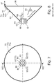
- the Figure 8 now shows schematically that the gas spreads in the direction of arrow 88 in the radial direction as a hydrogen flow, while the oxygen flow 89 is concentrated in a radially inner region.
- a split into the two gas flows 88 and 89 thus takes place in the area of the conical, bell-shaped vibration bodies 70a, 70b.
- a mixed gas stream is accordingly taken on different levels and at the same time a further gas component flows in the direction of arrow 46 over the tab 87 which is arranged at the edge and forms an annular gap in relation to the inner wall of the housing 44.
- the tab 87 and the radially outer flow gap 73 formed thereby can also be omitted.
- the separation of the radially inner gas streams 88, 89 is achieved by the different charging of the gas molecules, while the gas stream flowing outside in the circumferential area (direction of arrow 76) at the through-flow gap 73 consists of different mixed gas components.
- part of the gas flows over the outer circumference of the electrically positively charged anode shaft 68. This is shown in FIG Figure 7 shown, where it can be seen that there are recesses 82 between the round bars 72, through which the gas can flow along the surface of the positively charged anode shaft 68.
- the gas flows are further split into oxygen and hydrogen gas with the aid of oppositely charged electrically conductive disks, namely the cathode sheaths 69, which have a larger circumference and the anode disks 99, which have a smaller diameter.
- Such a differential voltage can be generated, for example, by a known electric pasture fence apparatus, such as that used in livestock farming for fencing cattle pastures.
- the pulse generator used here can be used with the same or modified pulse strength and the same or modified voltage difference as the known electric fence apparatus.
- anode and cathode plates 69, 99 are not only permanently or pulsed with direct current applied, but also individually dosed, for example with voltages in the range of 4, 8, 12V or 60, 120, 60V in any order, as well as pulse train and form.
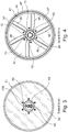
- bell-shaped resonance bodies 70a and 70b of the resonance device 70 form optional through-flow gaps 73 radially outwards in the direction of the inner wall of the housing, such through-flow gaps 73 are no longer necessary in the downstream anode and cathode disks 69, 99 because they have a large number of perforations for the gas passage have, as for example in Figure 5 is shown.
- the Figure 5 shows a plan view of the anode and cathode disks 69, 99, which are preferably arranged one inside the other in a vertical plane, each of the disks having a plurality of perforated bores 98 through which the gas flows.
- the holes 98 in the area of the cathode disk 69 and the anode disks 99 are dimensioned the same.
- the cathode disk is perforated with smaller bore diameters in the radially outer area and has larger throughflow windows in the radially inner area.
- the anode disk 99 is unaffected by this and has the previously mentioned holes 98.
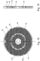
- Figures 15 and 16 show one opposite the Figure 5 modified embodiment in which the same parts are provided with the same reference numerals.
- the reference symbols in brackets show the positions in Figure 5 parts are positioned.
- the anode and cathode disks 69, 99 provided with the perforated bores 98 are joined into one another in a preferably vertical plane and can thus channel the gas flow even better and tap it in the extraction unit and also be more compact.
- the cathode voltage is applied to the outer section of the cathode disk 69 and the anode voltage to the inner section of the anode disk 99 closed insulating ring 109, preferably made of a ceramic material, electrically separated
- FIG. 2 the outlet end of the reactor vessel 44 is shown with a (in reality nonexistent) separating gap, which in practice forms a sealing surface 101 in the direction of a sealingly adjoining cover 102, in which an insulating block 71 for the one-sided, electrically insulated storage of the electrically charged anode shaft is arranged.
- a number of passage openings are provided in this cover 102, whereby it can be seen that the hydrogen gas flows radially outward in the direction of arrow 75 into a gas separator 47 connected to it, while the oxygen gas collects under the hydrogen gas and can thus be removed in separate chambers of the gas separator 47 .
- the hydrogen therefore collects in the hydrogen storage device 77 arranged above, while the oxygen collects in the oxygen storage device 78 arranged below.
- the oxygen can be withdrawn there via a withdrawal valve 50, while the hydrogen in the hydrogen storage device 77 can be withdrawn via a withdrawal valve and a feed line 51 arranged there.
- the process of dividing the gas flows into a hydrogen and oxygen flow 88, 89 can be further improved by arranging a semi-permeable membrane 80 in the area between the two gas reservoirs 77, 78, which separates the gas molecules of different sizes from one another.
- a drain hole 79 for condensed water can be arranged in the lower region of the gas separator 47, so that the condensed water can be fed to the water tank 17 in the direction of the arrow 22 via a return line 21.
- the resonance device 70 When the resonance device 70 is constructed with bell-shaped bodies 70a, 70b, cone walls 85 that engage in one another are preferred because a directed flow can be generated with such a large-area wall arrangement.
- the permanent magnets 59 are received in holders 92, the permanent magnets being arranged in recessed slots in the wall of the annular magnet sleeve 58.
- the magnetic ring sleeve 58 is made of a suitable coercive material.
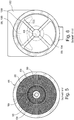
- the Figure 6 shows the section through the right-hand cover 102, where it can be seen that in the interior there is an insulating ring 100 with a number of spokes 103 arranged radially evenly distributed around the circumference, with a lower, approximately central one in the flow spaces separated from the spokes 103 according to the invention
- Oxygen region 104 forms for the separated oxygen flow 89, while a hydrogen cloud 105 with the separated hydrogen flow 88 is formed in the upper region of the cover.
- the advantage of the method according to the invention is that it is a continuous process because it is a serial sequence of different process stages according to FIG Figure 15 is, that is, it is an axially advancing gas flow that flows dynamically, while in the usual reactor vessels there is a static gas cloud that is conditioned.
- the invention has the advantage that a UV irradiation device 32 and an adjoining magnetizing device 34 use little energy to condition the water vapor flow, with small amounts of energy being required.
- the resonance device 39 arranged in the course of the flow picks up the natural resonance of the preconditioned water vapor and conditions it further with little expenditure of energy. The remaining energy is used to charge the capacitor plates, which requires considerably less energy than, for example, the known electrolysis processes or other comparable static processes. In this way, a higher gas yield can be achieved with lower energy input, which is based on a reactor vessel of the same volume.
- control parameters can be changed in the reactor cell 28, such as, for example, the frequency of the resonance device 39, the control voltage on the capacitor arrangement and the control voltage on the magnetization device 34.
- process parameters can also be changed within wide limits during the process in order to achieve an optimal process yield.
- a reactor cell 28 according to the invention with dimensions of approximately 500 mm in length and 250 mm in diameter and a weight of approximately 20 to 30 kg is capable of a gas flow of hydrogen and oxygen and / or Brown's gas in the range of 40 cbm / h. In this case, an electrical output of in the range from 60 to 100 kWh is required if no electricity-generating fuel cell 29 is used.
- These process parameters result in the particular suitability of such a device 1 for mobile use, in particular for the motor vehicle sector.
- such a gas generator is particularly suitable for all land, water and air vehicles.
Abstract
1. Verfahren zur Gewinnung von Brown's-Gas und/oder Sauerstoff und Wasserstoff, insbesondere für Verbrennungsmotoren oder Brennstoffzellen unter Anwendung eines physikalischen Spaltungsverfahrens unter Anwendung einer Abfolge von unterschiedlichen Erregungsverfahren bei HHO mit anschließender Trennung der Gase H2 und O2, wobei1.1 Wasser in eine Reaktorzelle (28) eingespeist wird1.2 danach die Wassermoleküle ionisiert werden1.3 danach durch Permanentmagneten oder Magnetspulen ausgerichtet werden,1.4 danach mit einem Radiosignal mit einer bestimmten Frequenz in Schwingung versetzt und einen Plasmazustand erreichen1.5 wobei In diesem Plasmazustand die Wassermoleküle speziell geformte und angeordnete Elektroden passiert, an denen spezifische Spannungen impulsweise angesteuert anliegen, wodurch eine Teilmenge Wasserstoff und Sauerstoff abgeschieden wird.1.6 wobei die nicht gespaltene Fraktion des Wassers in die Reaktorzelle (28) zurückgeführt wird und dadurch kontinuierlich höhere Erregungszustände erreicht, wodurch der Wirkungsgrad der Gaserzeugung gesteigert ist1. Process for the production of Brown's gas and / or oxygen and hydrogen, in particular for internal combustion engines or fuel cells using a physical splitting process using a sequence of different excitation processes for HHO with subsequent separation of the gases H2 and O2, where1.1 water into one Reactor cell (28) is fed1.2 then the water molecules are ionized1.3 then aligned by permanent magnets or magnetic coils, 1.4 then set in vibration with a radio signal with a certain frequency and reach a plasma state1.5 where in this plasma state the water molecules are specially shaped and arranged electrodes, to which specific voltages are applied in a pulsed manner, as a result of which a partial amount of hydrogen and oxygen is separated conditions reached, whereby the efficiency of gas generation is increased
Description
Gegenstand der Erfindung ist ein Verfahren und eine Vorrichtung zur Gewinnung von Browns-Gas und/oder Sauerstoff und Wasserstoff nach dem Oberbegriff des Patentanspruchs 1.The subject matter of the invention is a method and a device for the production of Browns gas and / or oxygen and hydrogen according to the preamble of
Den Hintergrund der Erfindung wird durch einen Internet-Auszug aus dem Lexikon WIKIPEDIA wie folgt beschrieben:
"Als HHO-Zelle wird eine Zelle bezeichnet, die zur Wasserelektrolyse in Kraftfahrzeugen verwendet wird. Bei der Verbrennung des Elektrolysegases im Motor soll eine Treibstoffersparnis erzielt werden.The background of the invention is described by an Internet excerpt from the WIKIPEDIA lexicon as follows:
"An HHO cell is a cell that is used for the electrolysis of water in motor vehicles. When the electrolysis gas is burned in the engine, fuel savings are to be achieved.
HHO-Zellen können als Nasszellen und Trockenzellen aufgebaut werden. Bei einer Nasszelle befinden sich die Elektroden in einem Gefäß und sind komplett von Wasser umspült. Das Gefäß ist gasdicht gebaut, damit das Gas in den Gasschlauch fließen kann.HHO cells can be set up as wet cells and dry cells. In a wet cell, the electrodes are located in a vessel and are completely surrounded by water. The vessel is built gas-tight so that the gas can flow into the gas hose.
Ganz anders ist der Aufbau der Trockenzelle. Dort kommt kein Gefäß zum Einsatz, sondern die Elektroden selbst bilden ein Gefäß, so dass die Zelle nach außen trocken bleibt. Während eine Nasszelle wie eine Wanne das Wasser für die Elektrolyse hält, muss bei einer Trockenzelle für einen Zulauf von Wasser gesorgt werden, denn die Trockenzelle würde ohne ständigen Wasserzulauf sehr schnell "austrocknen" und überhitzen. Für den Wasserzulauf sorgt ein Wassertank, der oberhalb der Trockenzelle angebracht werden muss, damit das Wasser durch die Schwerkraft in die Zelle fließen kann. Bei jeder Art von Zelle stehen sich immer Anode und Kathode in geringem Abstand gegenüber (meist 1,5 mm - 3 mm). Bei einer Trockenzelle sind die Elektroden oben und unten mit Löchern oder Schlitzen versehen, damit das Wasser unten durch die ganze Zelle laufen kann bzw. das Gas oben entweichen kann. Mit einer Gummidichtung in Ringform werden die Elektroden auf Abstand zueinander gehalten. Elektroden und Gummiringe bilden so das Gefäß der Trockenzelle, in der das Wasser elektrolysiert wird.The structure of the dry cell is completely different. No vessel is used there, but the electrodes themselves form a vessel so that the cell remains dry on the outside. While a wet cell, like a tub, holds the water for electrolysis, a dry cell has to provide for an inflow of water, because the dry cell would be without a constant water inflow "dry out" very quickly and overheat. The water inlet is provided by a water tank that must be installed above the dry cell so that the water can flow into the cell under the force of gravity. In every type of cell, the anode and cathode are always close to each other (usually 1.5 mm - 3 mm). In the case of a dry cell, the electrodes are provided with holes or slits at the top and bottom so that the water can run through the entire cell at the bottom and the gas can escape at the top. The electrodes are kept at a distance from one another with a rubber seal in the form of a ring. Electrodes and rubber rings thus form the vessel of the dry cell in which the water is electrolyzed.
Jede Trockenzelle hat einen Wassereinlauf (unten) und einen Gasauslass (oben). Zelle und Wassertank bilden somit einen Kreislauf. Ständig läuft Wasser aus dem Tank in die Zelle und Gas, vermischt mit Wasser, in den Tank zurück. Dieser Kreislauf dient nicht nur der Versorgung mit Wasser, sondern auch der Kühlung.Each dry cell has a water inlet (below) and a gas outlet (above). The cell and water tank thus form a cycle. Water constantly flows from the tank into the cell and gas, mixed with water, runs back into the tank. This circuit is not only used for the supply of water, but also for cooling.
Eine Zelle besteht aus einem Plattenstapel von Elektroden, die an die Bordnetzspannung des Fahrzeuges (12 oder 24 Volt) angeschlossen werden. Eine Zuführung liefert Wasser nach, während das Elektrolysegas (Knallgas, bestehend aus Wasserstoff und Sauerstoff) gemeinsam gesammelt wird [Zitat Ende].A cell consists of a stack of plates of electrodes that are connected to the vehicle's electrical system (12 or 24 volts). A feeder supplies water while the electrolysis gas (oxyhydrogen, consisting of hydrogen and oxygen) is collected together [end of quote].
Mit dem Gegenstand der
Ein solches Verfahren geht den Weg, aus einem HHO-Gas Wasser zu gewinnen. Nachteil dieses bekannten Verfahrens ist jedoch, dass der umgekehrte Weg im Vergleich zur Erfindung gegangen wird, nämlich dass aufgezeigt wird, wie aus einem Plasma Wasser zurückgewonnen wird. Die Bildung eines Hochtemperatur-Plasmas in einem Bereich von 2.800 °C bis 3.500 °C ist unerwünscht und erhöht die Kosten eines solchen bekannten Reaktors.One such method is to obtain water from an HHO gas. The disadvantage of this known method, however, is that the opposite route is taken compared to the invention, namely that it shows how water is recovered from a plasma. The formation of a high-temperature plasma in a range from 2,800 ° C. to 3,500 ° C. is undesirable and increases the costs of such a known reactor.
Mit dem Gegenstand der
Auch bei diesem bekannten Verfahren besteht ein Nachteil, dass hohe Prozesstemperaturen für die Gewinnung eines Plasmas vorausgesetzt werden und ferner besteht die Notwendigkeit, dass für die Plasmaverarbeitung Katalysatoren eingesetzt werden, was die Herstellungskosten und den Unterhalt einer solchen Anlage erhöht.This known method also has a disadvantage that high process temperatures are required for the production of a plasma and there is also the need to use catalysts for the plasma processing, which increases the production costs and the maintenance of such a system.
Beide genannten Anlagen sind nicht in der Lage, als kleine transportable Reaktoren, beispielsweise zur Gewinnung von Browns-Gas und/oder Sauerstoff und Wasserstoff in Kraftfahrzeugen oder anderen mobilen Anlagen, verwendet zu werden.Both of these plants are not able to be used as small transportable reactors, for example for the production of Browns gas and / or oxygen and hydrogen in motor vehicles or other mobile plants.
Auch die Verwendung für den Allgemeingebrauch, z.B. als Heizungsanlage im Keller von Wohnhäusern, ist für solche Anlagen nicht anwendbar.The use for general use, e.g. as a heating system in the basement of residential buildings, is also not applicable for such systems.
Die gleiche Kritik gilt auch für die
Die von dem Reaktor in radialer Richtung einwärts abgegebene Energie wird von den Wassermolekülen aufgenommen und es erfolgt eine Aufspaltung in Wasserstoff und Sauerstoff.The energy given off in the radial direction inwards by the reactor is absorbed by the water molecules and it is split into hydrogen and oxygen.
Nachteil dieser bekannten Vorrichtung ist ebenfalls der hohe Energieeinsatz, die hohen Prozesstemperaturen und die fehlende Anwendbarkeit für den Alltagsgebrauch.The disadvantage of this known device is also the high energy consumption, the high process temperatures and the lack of applicability for everyday use.
Der Erfindung liegt deshalb die Aufgabe zugrunde, ein Verfahren und eine Vorrichtung zur Gewinnung von Browns-Gas und/oder Sauerstoff und Wasserstoff so weiterzubilden, dass eine einfach zu handhabende, relativ kostengünstig herstellbare Anlage erreicht wird, bei der es möglich ist, mit relativ kleinem Energieeinsatz eine große Ausbeute von Browns-Gas und/oder Wasserstoff zu ermöglichen.The invention is therefore based on the object of developing a method and a device for the production of Browns gas and / or oxygen and hydrogen in such a way that an easy-to-use, relatively inexpensive to manufacture system is achieved in which it is possible to use relatively small Use of energy to enable a large yield of Browns gas and / or hydrogen.
Bei dem Verfahren zur Erzeugung von Wasserstoff und Sauerstoff und/oder Brown's-Gas aus Wasser handelt es sich um ein physikalisches Spaltungsverfahren unter Anwendung einer Abfolge von unterschiedlichen Erregungsverfahren bei HHO mit anschließender Trennung der Gase H2 und O2.The process for generating hydrogen and oxygen and / or Brown's gas from water is a physical splitting process using a sequence of different excitation processes in HHO with subsequent separation of the gases H2 and O2.
Die Erfindung betrifft ein Verfahren zur Erzeugung von Wasserstoff / Browns-Gas aus Wasser, bei dem das Wasser einen dynamischen Prozess durchläuft und dabei verschiedenen Erregungsverfahren ausgesetzt wird. Elektrolyte oder Katalysatoren sind bei dem Verfahren nicht erforderlich, könnten aber förderlich sein.The invention relates to a method for generating hydrogen / Browns gas from water, in which the water runs through a dynamic process and is exposed to various excitation methods. Electrolytes or catalysts are not required in the process, but could be beneficial.
Bei dem Verfahren wird das Wasser nach einer ersten Verfahrensvariante mit einer Einspritzdüse in einen Reaktor eingespritzt, der zu Beginn des Prozesses drucklos im Vergleich zur Umgebungsluft ist. In einer zweiten Verfahrensvariante erfolgt die Einspeisung von Wasser in den Reaktor ohne Verwendung einer Einspritzpumpe.In the process, the water is injected into a reactor according to a first process variant with an injection nozzle, which at the beginning of the process is depressurized compared to the ambient air. In a second variant of the method, water is fed into the reactor without the use of an injection pump.
Bei dem Verfahren wird das Wasser in einem Kreislauf zunächst mit einer Pumpe in Zirkulation versetzt. Beim Passieren eines Reaktors wird das Wasser zunächst ionisiert, durch Permanentmagneten oder Magnetspulen ausgerichtet, mit einem Radiosignal mit einer bestimmten Frequenz in Schwingung versetzt und erreicht so einen Plasmazustand. In diesem Plasmazustand passiert das Wasser speziell geformte und angeordnete Elektroden, an denen spezifische Spannungen permanent und/oder impulsweise angesteuert anliegen, wodurch eine Teilmenge Wasserstoff und Sauerstoff abgeschieden werden. Die nicht gespaltene Fraktion des Wassers verbleibt in Zirkulation und erreicht kontinuierlich höhere Erregungszustände, wodurch der Wirkungsgrad ansteigt. Frischwasser kann permanent zugeführt werden.In the process, the water is first put into circulation in a circuit using a pump. When passing through a reactor, the water is first ionized, aligned by permanent magnets or magnetic coils, and made to vibrate with a radio signal at a certain frequency and thus reaches a plasma state. In this plasma state, the water passes specially shaped and arranged electrodes to which specific voltages are applied permanently and / or in a pulsed manner, as a result of which a subset of hydrogen and oxygen are separated. The non-split fraction of the water remains in circulation and continuously reaches higher levels of excitement, which increases the efficiency. Fresh water can be supplied permanently.
Vorteil der Erfindung ist es, ein Verfahren der eingangs erwähnten Art zur Gewinnung von Wasserstoff / Brown's-Gas so auszubilden, dass es gleichzeitig möglichst kostengünstig und ökologisch verträglich zu realisieren ist. Dabei besteht der Anspruch, bei gleichem Energieeinsatz wie er bei Elektrolyseverfahren zum Einsatz kommt eine größere Volumenmenge Wasserstoffgas zu gewinnen. Das Verfahren soll in seiner Auslegung sowohl stationär als auch mobil anwendbar sein.The advantage of the invention is to design a method of the type mentioned at the beginning for the production of hydrogen / Brown's gas in such a way that it can be implemented at the same time as cost-effectively and ecologically compatible as possible. There is a requirement to obtain a larger volume of hydrogen gas with the same amount of energy as is used in electrolysis processes. The design of the method should be applicable both stationary and mobile.
Wesentlicher Teil der Erfindung ist im Gegensatz zu statischen Elektrolyseverfahren die dynamische Skalierbarkeit. Durch den Eingriff in Steuerparameter wie Volumenfluss, Frequenz, Magnetstärke und Spannung lässt sich die Menge der erzeugten Gase im Betrieb dynamisch anpassen. Dies erlaubt eine dosierte bedarfsgerechte Bereitstellung spezifischer Gasmengen für Anforderungen bei mobilen Anwendungen in der Fahrdynamik oder im Prozessfluss bei industriellen Anwendungen.In contrast to static electrolysis processes, an essential part of the invention is dynamic scalability. By intervening in control parameters such as volume flow, frequency, magnet strength and voltage, the amount of gases generated can be dynamically adjusted during operation. This allows a dosed, needs-based supply of specific gas quantities for requirements in mobile applications in vehicle dynamics or in the process flow in industrial applications.
Weiterhin ist es Aufgabe der Erfindung eine Vorrichtung zur Durchführung eines solchen Verfahrens bereit zu stellen. Das Verfahren hat in erster Linie den Vorteil die bekannten Nasszellen- Elektrolyseverfahren zu vermeiden, indem der bekannte statische Prozess durch einen dynamischen Prozess ersetzt wird.Another object of the invention is to provide a device for carrying out such a method. The process primarily has the advantage of avoiding the known wet cell electrolysis process by replacing the known static process with a dynamic process.
Im Gegensatz zu bekannten Trockenzellen- Verfahren wird der Volumenstrom des Wassers nicht allein bei geringer Dynamik durch Metallplatten mit elektrischer Ladung geschleust, sondern in einem schnelleren hydraulischen und/oder pneumatischen Fluss teilweise mehrfach durch den Reaktor geführt.In contrast to known dry-cell processes, the volume flow of the water is not only passed through metal plates with an electrical charge with low dynamics, but is sometimes conducted several times through the reactor in a faster hydraulic and / or pneumatic flow.
Beim Passieren des Reaktors wird das Wasser zunächst ionisiert. Dies kann je nach Anwendung durch bestimmte Permanentmagnete und Elektromagnete, durch UV-Licht, durch Anlegen einer Gleichspannung oder Passieren eines biokeramischen Filters erfolgen.When passing through the reactor, the water is first ionized. Depending on the application, this can be achieved by certain permanent magnets and electromagnets, by UV light, by applying a direct voltage or passing through a bioceramic filter.
Im nächsten Verfahrensschritt wird das Wasser mit einer Radiofrequenz innerhalb des Reaktors impulsweise erregt und wird so mindestens teilweise in einen Plasmazustand versetzt.In the next process step, the water is excited in pulses with a radio frequency inside the reactor and is thus at least partially converted into a plasma state.
Im folgenden Verfahrensschritt wird das Wasser im gemischten Aggregatzustand über eine Anordnung von Elektroden geführt, die quer zur Strömungsrichtung angeordnet sind und in Strömungsrichtung mit ausreichenden Reaktionsoberflächen ausgestattet sind und die permanent und/oder impulsweise mit einer festgelegten, höheren Impuls- und/oder Gleichspannung beaufschlagt werden. Dadurch scheiden sich Wasserstoff- und Sauerstoffatome unter relativ geringer Energieeinwirkung ab.In the following process step, the water in the mixed state of aggregation is passed over an arrangement of electrodes which are arranged transversely to the direction of flow and are equipped with sufficient reaction surfaces in the direction of flow and which are permanently and / or pulsed with a fixed, higher pulse and / or DC voltage . As a result, hydrogen and oxygen atoms separate with relatively little energy.
Der bei Einspeisung erzeugte Wasserstrom oder der bei Einspritzung entstehende Wassernebel wird weiter in Zirkulation gehalten, während das gelöste Gas nach oben abgeschieden wird.The water flow generated during the feed or the water mist produced during injection is kept in circulation while the dissolved gas is separated upwards.
Je nach Folgeanwendungen wird das Gas als Brown-Gas durch ein oder mehrere Gaswäscher (Bubbler), Partikelfilter und Rückschlagventile der direkten Anwendung zugeführt oder in einem Gasabscheider in H2 und O2 aufgeteilt und so der Verwendung oder Speicherung zugeführt.Depending on the subsequent application, the gas is fed as brown gas through one or more gas washers (bubblers), particle filters and non-return valves for direct use or divided into H2 and O2 in a gas separator and thus fed to use or storage.
Das Verfahren eignet sich sowohl für Süßwasser in unterschiedlichen Qualitäten (Regenwasser, Oberflächenwasser, Brunnenwasser, Kondenswasser, destilliertes Wasser, Grauwasser aus Klärprozessen etc.), als auch für Salzwasser ohne vorherige Entsalzung.The process is suitable both for fresh water in different qualities (rainwater, surface water, well water, condensation water, distilled water, gray water from sewage processes, etc.), as well as for salt water without prior desalination.
Der Zusatz von kristallinen Katalysatoren und Elektrolyten als Beimischung im Wasser oder die Durchströmung durch einen metallischen Permanentkatalysator kann erwogen werden und kann die Reaktionsgeschwindigkeit nochmals steigern, ist aber nicht zwingend erforderlich.The addition of crystalline catalysts and electrolytes as an admixture in the water or the flow through a metallic permanent catalyst can be considered and can further increase the reaction rate, but is not absolutely necessary.
Dies kann fallweise nach Abwägung des ökologischen Fußabdrucks unter Berücksichtigung aller Ressourcen (Energie wie Material) erwogen werden.This can be considered on a case-by-case basis after weighing up the ecological footprint, taking into account all resources (energy and material).
Anwendungen: das so gewonnene Gas kann ebenso wie klassisch erzeugter Wasserstoff oder Brown's Gas als Brennstoff z.B. für Schweißgeräte, Industriefeuerung, Heizanlagen u. a. eingesetzt werden. Es kann zur Abgasneutralisation in Verbrennungsmaschinen und thermischen Anlagen im Prozess oder nachgeordnet zur Abgasneutralisierung eingesetzt werden. Im Transportsektor können mit dieser Technologie Wasserstofftankstellen ohne Tanklager realisiert werden, die das Gas in bedarfsgerechten Portionen erzeugen. In der dynamischen Anwendung kann für Fahrzeuge zu Land, Wasser und der Luft Wasserstoff oder Brown's Gas nach dem momentanen Bedarf der Fahrdynamik erzeugt werden. Eine Speicherung von Gas ist im Fahrzeug nicht erforderlich. Die Umwandlung in kinetische oder elektrische Energie kann dabei sowohl durch Verbrennungsmotoren als auch durch Brennstoffzellen erfolgen.Applications: the gas obtained in this way can be used as a fuel, just like conventionally produced hydrogen or Brown's gas, e.g. for welding equipment, industrial firing, heating systems, etc. can be used. It can be used for exhaust gas neutralization in combustion engines and thermal systems in the process or downstream for exhaust gas neutralization. In the transport sector, this technology can be used to implement hydrogen filling stations without tank farms, which generate the gas in needs-based portions. In the dynamic application, hydrogen or Brown's Gas can be generated for vehicles on land, water and air according to the current requirements of the driving dynamics. It is not necessary to store gas in the vehicle. The conversion into kinetic or electrical energy can be done by internal combustion engines as well as by fuel cells.
Besonderheiten / Modifikationen beim Einsatz in Verbrennungsmotoren:
- 1. Im Gegensatz zum Luft-Kraftstoff-Gemisch reagiert Brown's Gas durch Implosion. Das bedeutet, dass bei Betrieb mit purem Gas ein entsprechend großer Brennraum erforderlich, ist und die Zündung um bis zu 30° (je nach Motor) vorgestellt werden muss, um den Motor durch Sog, statt durch Volumenausdehnung zu bewegen.
- 2. eine Alternative ist die Mischung des separierten Wasserstoff -Gases mit Wasserdunst. Dieser liefert eine Reaktionsoberfläche, die eine Dampfexpansion des Wassers ausgelöst durch die Knallgaszündung ermöglicht. Der Eintrag des Wassernebels kann wie bei anderen Verfahren, die z.B. mit einem Wasserstofftank arbeiten, per Venturidüse erfolgen. Allerdings erlaubt der steuerbare Prozess der Wasserstoff- / Brown's Gas-Erzeugung eine direkte Kopplung beider Prozesse und die bedarfsgerechte Einspritzung von Gas und Wassernebel im optimalen Mischungsverhältnis mittels einer Einspritzdüse.
- 3. Detaillierte Beschreibung der Erfindung Zur Lösung der gestellten Aufgabe ist die Erfindung demnach durch ein Verfahren gekennzeichnet, welches aus mehreren hintereinander geschalteten Prozessschritten besteht, wobei im ersten Prozessschritt wahlweise eine Einspritzung oder eine Einspeisung von Wasser in den Einlauf einer Reaktorzelle erfolgt, dass in einem zweiten Prozessschritt eine Ionisierung des eingetragenen Wassers mithilfe von UV-Strahlen stattfindet und hieraus ein Plasma entsteht, dass im dritten Prozessschritt eine Magnetisierung des gebildeten Plasmas mit Bildung eines Verwirbelungsstromes erfolgt, dass in einer vierten Stufe eine Resonanzerregung des so gebildeten, verwirbelten Plasmas erfolgt und dass am Ausgang der vierten Stufe ein Gaszerfall und wahlweise entweder eine Aufspaltung in Wasserstoff und Sauerstoff erfolgt oder ein Mischgas in Form eines HHO-Gases (Brown's-Gas) erfolgt.
- 1. In contrast to the air-fuel mixture, Brown's Gas reacts by implosion. This means that when operating with pure gas, a correspondingly large combustion chamber is required and the ignition must be advanced by up to 30 ° (depending on the engine) in order to move the engine by suction instead of volume expansion.
- 2. An alternative is to mix the separated hydrogen gas with water vapor. This provides a reaction surface that enables steam to expand in the water triggered by the oxyhydrogen ignition. The entry of the water mist can be carried out using a Venturi nozzle, as in other processes that work, for example, with a hydrogen tank. However, the controllable process of hydrogen / Brown's gas generation allows a direct coupling of both processes and the needs-based injection of gas and water mist in the optimal mixing ratio by means of an injection nozzle.
- 3. Detailed description of the invention To solve the problem, the invention is characterized by a method which consists of several process steps connected one after the other, with an injection or a feed of water into the inlet of a reactor cell optionally taking place in the first process step, and in a second process step an ionization of the entered Water takes place with the help of UV rays and a plasma is created from this, that in the third process step a magnetization of the formed plasma takes place with the formation of a turbulence current, that in a fourth stage a resonance excitation of the thus formed, turbulent plasma takes place and that at the exit of the fourth stage Gas decomposition and optionally either a breakdown into hydrogen and oxygen takes place or a mixed gas takes place in the form of an HHO gas (Brown's gas).
Ist eine weitere Abtrennung des Gasgemisches aus Wasserstoff und Sauerstoff gewünscht, dann ist für diesen Fall eine fünfte Stufe vorgesehen, bei der im Bereich eines elektrischen Feldes mit einer Pulsspannung oder eine Gleichspannung eine Aufspaltung des Gasstromes in Wasserstoff und Sauerstoff erfolgt.If a further separation of the gas mixture of hydrogen and oxygen is desired, a fifth stage is provided for this case, in which the gas flow is split into hydrogen and oxygen in the area of an electric field with a pulse voltage or a direct voltage.
Bei der genannten Prozessabfolge wird es bevorzugt, wenn bereits schon beim Ausgang der vierten Stufe das HHO-Mischgas abgezapft wird, um so das gewonnene Brown's-Gas einer weiteren Verarbeitung zuzuführen.In the process sequence mentioned, it is preferred if the HHO mixed gas is already tapped off at the exit of the fourth stage in order to feed the Brown's gas obtained for further processing.
Am Ausgang der fünften Stufe, wenn demnach in einem elektrischen Feld das Sauerstoffgas vom Wasserstoffgas getrennt wurde, können die beiden so getrennten Gasströme in einer sechsten Stufe einem Verbraucher zugeführt werden, der z.B. eine Brennstoffzelle, ein Verbrennungsmotor, eine Abgasmitigation oder ein anderer industrieller Prozess ist.At the exit of the fifth stage, if the oxygen gas has been separated from the hydrogen gas in an electric field, the two gas flows separated in this way can be fed in a sixth stage to a consumer, which is, for example, a fuel cell, an internal combustion engine, an exhaust gas mitigation or another industrial process .
Wichtig bei den dargestellten Prozessstufen ist, dass mit relativ geringem Energieeinsatz eine hohe Prozessausbeute erfolgt, denn elektrischer Strom wird lediglich in der Ionisierungsstufe (zweite Stufe) in geringem Umfang benötigt, ferner in der dritten Stufe, um eine Magnetisierung mit der Verwirbelung des Plasmagases zu erreichen (entfällt bei Einsatz von Permanentmagneten) und ferner auch in der vierten Stufe, wo eine Resonanzerregung mithilfe einer elektrischen Spannung stattfindet.In the process stages shown, it is important that a high process yield is achieved with relatively little energy input, because electrical power is only required to a small extent in the ionization stage (second stage) and also in the third stage in order to achieve magnetization with the swirling of the plasma gas (not applicable when using Permanent magnets) and also in the fourth stage, where resonance excitation takes place with the aid of an electrical voltage.
Es handelt sich in den verschiedenen beschriebenen Stufen um Niederstromanwendungen, was mit dem Vorteil verbunden ist, dass die genannte neuartige Anlage keinen hohen Stromverbrauch hat.In the various stages described, these are low-current applications, which is associated with the advantage that the above-mentioned novel system does not have a high power consumption.
In einer abgewandelten Ausführungsform ist es erfindungsgemäß vorgesehen, dass die zweite Stufe (Ionisierung) gegen die dritte Stufe ausgetauscht wird, d.h. es wird in diesem abgewandelten Ausführungsbeispiel zunächst die dritte Stufe durchlaufen, an die sich die zweite Stufe anschließt.In a modified embodiment, it is provided according to the invention that the second stage (ionization) is exchanged for the third stage, i.e. in this modified embodiment the third stage is first run through, followed by the second stage.
Wenn in der vorliegenden Beschreibung davon die Rede war, dass in der dritten Stufe eine Magnetisierung mit einer Verwirbelung stattfindet, so ist eine solche Magnetisierung mit verschiedenen Vorrichtungsmerkmalen zu verwirklichen.If it was mentioned in the present description that magnetization with a swirl takes place in the third stage, then such magnetization can be achieved with various device features.
In einer ersten Ausgestaltung kann es vorgesehen sein, dass die Magnetisierung vorzugsweise mithilfe von Permanentmagneten erfolgt, die gleichmäßig am Umfang einer Magnet-Ringbuchse verteilt angeordnet sind.In a first embodiment, it can be provided that the magnetization is preferably carried out with the aid of permanent magnets, which are arranged distributed uniformly on the circumference of a magnetic ring socket.
Statt der Verwendung von Permanentmagneten ist es selbstverständlich auch möglich, mit Strom versorgte Spulen zu verwenden, die einen gleichen Magnetisierungseffekt ausüben.Instead of using permanent magnets, it is of course also possible to use coils which are supplied with current and which exert the same magnetization effect.
Die vierte Stufe, die auf eine Resonanzerregung ausgerichtet ist, soll vorzugsweise mit einer Frequenzerregung im Mikrowellenbereich erfolgen. Hierzu ist ein geeigneter Frequenzgenerator erforderlich, der beispielsweise im Frequenzbereich 100 bis 200 MHz arbeitet.The fourth stage, which is aimed at resonance excitation, should preferably take place with frequency excitation in the microwave range. A suitable frequency generator is required for this, which operates, for example, in the frequency range 100 to 200 MHz.
Bevorzugt wird hierbei ein Frequenzbereich im Bereich von 124 bis 132 MHz.A frequency range in the range from 124 to 132 MHz is preferred here.
In einer anderen Ausgestaltung sind selbstverständlich auch andere Mikrowellenerreger möglich, wie z.B. eine Infraschall oder Ultraschall-Resonanzerregung.In another embodiment, other microwave exciters are of course also possible, such as infrasound or ultrasonic resonance excitation.
In einer bevorzugten Ausgestaltung schließt sich an die Resonanzerregung eine fünfte Stufe mit der Erzeugung eines elektrischen Feldes an.In a preferred embodiment, the resonance excitation is followed by a fifth stage with the generation of an electric field.
Versuche haben gezeigt, dass die Anordnung eines elektrischen Feldes zur Aufspaltung von Wasserstoff und Sauerstoff nicht unbedingt lösungsnotwendig ist, aber bevorzugt wird.Experiments have shown that the arrangement of an electric field for splitting hydrogen and oxygen is not absolutely necessary for the solution, but is preferred.
Geht es nur um die Gewinnung von Brown's-Gas, dann kann die fünfte Stufe mit der Erzeugung des elektrischen Feldes zur Trennung von Sauerstoff und Wasserstoff vollständig entfallen.If it is only about the production of Brown's gas, then the fifth stage with the generation of the electric field for the separation of oxygen and hydrogen can be completely omitted.
In einer bevorzugten Ausgestaltung wird eine Vorrichtung beschrieben, wie sie bevorzugt für die Gewinnung von Brown's-Gas und/oder Wasserstoff und Sauerstoff für die Brennstoffzuführung eines Verbrennungsmotors vorgesehen ist.In a preferred embodiment, a device is described as it is preferably provided for the production of Brown's gas and / or hydrogen and oxygen for the fuel supply of an internal combustion engine.
Ein solcher Verbrennungsmotor kann ein Hubkolbenmotor, ein Drehkolbenmotor oder ein anderer geeigneter Motor sein, der geeignet ist, über einen Verbrennungsvorgang eine mechanische Energie an einer Abtriebswelle (Kurbelwelle) zu erzeugen.Such an internal combustion engine can be a reciprocating piston engine, a rotary piston engine or another suitable engine which is suitable for generating mechanical energy on an output shaft (crankshaft) via a combustion process.
In einem bevorzugten Ausführungsbeispiel wird deshalb ein geschlossener Kreislauf für die Brennstoffversorgung eines Verbrennungsmotors beschrieben, bei dem in die Verbrennungsräume des Verbrennungsmotors Wasser in flüssiger Form und gleichzeitig ein aus dem Reaktor gewonnenes Wasserstoffgas eingespritzt werden.In a preferred exemplary embodiment, a closed circuit for the fuel supply of an internal combustion engine is therefore described, in which water in liquid form and, at the same time, a hydrogen gas obtained from the reactor are injected into the combustion chambers of the internal combustion engine.
Damit wird die Energiebilanz eines solchen Verbrennungsmotors entscheidend verbessert auch werden die Abgaswerte verbessert. Damit wird erreicht, dass auf fossile Brennstoffe, wie z.B. Benzin oder Dieseltreibstoff, verzichtet werden kann, und nur noch am Ausgang des Verbrennungsvorganges Wasserdampf erzeugt wird.In this way, the energy balance of such an internal combustion engine is decisively improved, and the exhaust gas values are also improved. This means that fossil fuels, such as gasoline or diesel fuel, can be dispensed with and water vapor is only generated at the exit of the combustion process.
Eine solche Vorrichtung kann auch für stationäre Verbrennungsmotoren verwendet werden, wie sie als Blockheizkraftwerk in Kelleranlagen von Wohnhäusern verwendet werden.Such a device can also be used for stationary internal combustion engines, such as those used as a combined heat and power unit in the basement of residential buildings.
In einer weiteren bevorzugten Ausgestaltung einer Vorrichtung wird ein geschlossener Kreislauf vorgesehen, der ausgehend von flüssigem Wasser, welches in einem Wassertank vorrätig ist, eine bestimmte Menge in die Eingangsseite einer Reaktorzelle einspritzt oder einfließen lässt und dann die vorher genannten Prozessstufen nacheinander folgend ablaufen.In a further preferred embodiment of a device, a closed circuit is provided, which, starting from liquid water which is available in a water tank, adds a certain amount to the The inlet side of a reactor cell is injected or allowed to flow in and then the previously mentioned process stages run one after the other.
In der bevorzugten Ausgestaltung besteht die Reaktorzelle aus einem druckfesten, eingangsseitig abgeschlossenen Metallgehäuse, an dessen Eingangsseite nunmehr über eine Einspritzdüse oder ein Einlassventil ein Wasserstrom einläuft und/oder ein Wasserstrahl eingespritzt wird. Danach erfolgt im Rahmen der zweiten Prozessstufe eine Ionisierung.In the preferred embodiment, the reactor cell consists of a pressure-resistant metal housing closed on the inlet side, on the inlet side of which a water stream now flows in via an injection nozzle or an inlet valve and / or a water jet is injected. This is followed by ionization as part of the second process stage.
Mit der Ionisierung werden die Wassermoleküle ionisiert und ausgerichtet, sodass sich damit ein bestimmter orientierter Molekülverbund ergibt, der in der dritten Stufe einer Magnetisierung unterworfen wird, die vorzugsweise eine zusätzliche spiralförmige Verwirbelung erzeugt, die um die in Längsrichtung gerichtete Strömungsachse gerichtet ist.With the ionization, the water molecules are ionized and aligned, so that a certain oriented molecular compound results, which is subjected to magnetization in the third stage, which preferably generates an additional spiral vortex, which is directed around the longitudinally directed flow axis.
Im Bereich dieser Magnetisierungsstufe werden die ausgerichteten Wassermoleküle in ein Plasma umgewandelt. Damit wird der Molekülstrom in eine bestimmte achsiale Richtung ausgerichtet, sodass die Energie der Wassermoleküle einen Energieeintrag erzeugt und die Bildung eines Plasmas verbessern.In the area of this magnetization level, the aligned water molecules are converted into a plasma. This aligns the flow of molecules in a certain axial direction, so that the energy of the water molecules generates an energy input and improves the formation of a plasma.
Die verwendeten Magnetfeldstärken richten sich nach der Größe des Reaktors und nach der Größe des Volumenstromes des ausgerichteten Molekülstroms, welcher aus der zweiten Stufe entstammt; es können Werte im Bereich von 0,1 bis 10,0 Tesla verwendet werden.The magnetic field strengths used depend on the size of the reactor and on the size of the volume flow of the aligned molecular flow, which originates from the second stage; values in the range from 0.1 to 10.0 Tesla can be used.
In einer ersten Ausgestaltung ist es vorgesehen, dass die Magnetisierung mit Permanentmagneten erfolgt, d.h. es handelt sich um ein statisches Magnetfeld, während in einer zweiten, alternativen Ausführungsform vorgesehen ist, dass ein gepoltes Magnetfeld verwendet wird, welches eine gepulste Magnetisierung mithilfe von Magnetspulen erreicht.In a first embodiment it is provided that the magnetization takes place with permanent magnets, i.e. it is a static magnetic field, while in a second, alternative embodiment it is provided that a polarized magnetic field is used, which achieves a pulsed magnetization with the aid of magnetic coils.
Die Pulsfrequenz in diesem zweiten Ausführungsbeispiel liegt im Bereich zwischen 0,01 Hz bis 10 Hz. Der so in der Magnetisierungsstufe gebildete Plasmastrom ist bevorzugt ein Spiralstrom, der in achsialer Richtung des Reaktors eine bestimmte Verwirbelungsstruktur zeigt. Der so verwirbelte Plasmastrom wird nun in den Bereich einer Resonanz-Vorrichtung gebracht.The pulse frequency in this second exemplary embodiment is in the range between 0.01 Hz to 10 Hz. The plasma flow thus formed in the magnetization stage is preferably a spiral current that flows in the axial direction of the Reactor shows a certain turbulence structure. The plasma flow swirled in this way is now brought into the range of a resonance device.
Diese Resonanz-Vorrichtung besteht bevorzugt aus mindestens zwei glockenförmigen, im gegenseitigen Abstand und isoliert voneinander angeordneten glockenförmigen Körpern, die elektrisch leitfähig sind, wobei zwischen beiden glockenförmigen Körpern eine Mikrowellenfrequenz angelegt ist, die im Bereich des o.g. Frequenzbandes liegt.This resonance device preferably consists of at least two bell-shaped, mutually spaced and insulated bell-shaped bodies, which are electrically conductive, with a microwave frequency being applied between the two bell-shaped bodies, which is in the range of the above-mentioned frequency band.
Somit wird im Zwischenraum zwischen den beiden leitfähigen glockenförmigen Körpern ein hochfrequentes Mikrowellenresonanzfeld erzeugt, welches in seiner Frequenz so abgestimmt ist, dass es mit der Frequenz der Molekülstruktur des gebildeten Plasmas übereinstimmt.Thus, a high-frequency microwave resonance field is generated in the space between the two conductive, bell-shaped bodies, the frequency of which is tuned so that it matches the frequency of the molecular structure of the plasma formed.
Hier soll dann die Mehrzahl der gebildeten Moleküle zerfallen oder sich zu dem Brown's-Gas "aufstrecken", d.h. es liegt ein loser Molekülverbund oder sogar schon eine Trennung der Moleküle vor.Here, the majority of the molecules formed should then disintegrate or "stretch out" into Brown's gas, i.e. there is a loose molecular compound or even a separation of the molecules.
Am Ausgang dieser vierten Stufe (Resonanzerregung) erfolgt demnach bereits schon ein Gaszerfall in ein Mischgas bestehend aus Sauerstoff und Wasserstoff oder wahlweise ein Mischgas bestehend aus dem Browns-Gas HHO.At the output of this fourth stage (resonance excitation) there is already a gas breakdown into a mixed gas consisting of oxygen and hydrogen or optionally a mixed gas consisting of Browns gas HHO.
Am Ausgang dieser vierten Stufe kann das Browns-Gas bereits schon abgezapft und einer weiteren Verarbeitung zugeführt werden.At the exit of this fourth stage, the Browns gas can already be tapped and sent for further processing.
Ist es hingegen gewünscht, dass das Mischgas aus Wasserstoff und Sauerstoff noch weiter abgetrennt wird, erfolgt die Weiterverarbeitung in der fünften Stufe im Bereich eines elektrischen Feldes.If, on the other hand, it is desired that the mixed gas of hydrogen and oxygen is separated even further, further processing takes place in the fifth stage in the area of an electric field.
Dieses elektrische Feld besteht aus in achsialer Richtung abwechselnd polarisiert angeordneten Kondensatorplatten, die als gerade, gelochte Scheiben ausgebildet sind und beim Durchgang durch das zwischen den Scheiben ausgebildete abwechselnd polarisierte elektrostatische Feld erfolgt ein Zerfall des Mischgases in die Einzelgase Wasserstoff und Sauerstoff.This electric field consists of capacitor plates arranged alternately polarized in the axial direction, which are designed as straight, perforated disks and when passing through the alternately polarized electrostatic field formed between the disks, the mixed gas breaks down into the individual gases hydrogen and oxygen.
Am Ausgang dieser fünften Stufe kann somit eine getrennte Entnahme von Sauerstoff und Wasserstoff erfolgen und wahlweise eines oder beide Gase einem Verbraucher zugeführt werden, wie z.B. eine Brennstoffzelle, einem Verbrennungsmotor, einer Abgasmitigation, oder einem anderen industriellen Prozess, insbesondere auch einem Blockheizkraftwerk.At the exit of this fifth stage, oxygen and hydrogen can be withdrawn separately and optionally one or both gases be fed to a consumer, such as a fuel cell, an internal combustion engine, an exhaust gas mitigation, or another industrial process, in particular also a block-type thermal power station.
Der Erfindungsgegenstand der vorliegenden Erfindung ergibt sich nicht nur aus dem Gegenstand der einzelnen Patentansprüche, sondern auch aus der Kombination der einzelnen Patentansprüche untereinander.The subject matter of the present invention results not only from the subject matter of the individual patent claims, but also from the combination of the individual patent claims with one another.
Alle in den Unterlagen, einschließlich der Zusammenfassung offenbarten Angaben und Merkmale, insbesondere die in den Zeichnungen dargestellte räumliche Ausbildung, könnten als erfindungswesentlich beansprucht werden, soweit sie einzeln oder in Kombination gegenüber dem Stand der Technik neu sind. Die Verwendung der Begriffe "wesentlich" oder "erfindungsgemäß" oder "erfindungswesentlich" ist subjektiv und impliziert nicht, dass die so benannten Merkmale zwangsläufig Bestandteil eines oder mehrerer Patentansprüche sein müssen.All information and features disclosed in the documents, including the summary, in particular the spatial configuration shown in the drawings, could be claimed as being essential to the invention, insofar as they are new, individually or in combination, compared to the state of the art. The use of the terms “essential” or “according to the invention” or “essential to the invention” is subjective and does not imply that the features named in this way must necessarily be part of one or more patent claims.
Im Folgenden wird die Erfindung anhand von lediglich mehreren Ausführungswege darstellenden Zeichnungen näher erläutert. Hierbei gehen aus den Zeichnungen und ihrer Beschreibung weitere erfindungswesentliche Merkmale und Vorteile der Erfindung hervor.In the following, the invention is explained in more detail with reference to drawings showing only several possible embodiments. Further features and advantages of the invention that are essential to the invention emerge from the drawings and their description.
Es zeigen:
-
Figur 1 : Schematisiert ein erstes Ausführungsbeispiel für eine Vorrichtung nach der Erfindung in der Anwendung an einem Verbrennungsmotor -
Figur 2 : Schematisiert die inFigur 1 -
Figur 3 : Ein Schnitt gemäß der Linie III-III inFigur 2 -
Figur 4 : Ein Schnitt gemäß der Linie IV-IV inFigur 2 -
Figur 5 : Ein Schnitt gemäß der Linie V-V inFigur 2 -
Figur 6 : Ein Schnitt gemäß der Linie VI-VI inFigur 2 -
Figur 7 : Eine Frontansicht eines Schwingungskörpers, der im bevorzugten Ausführungsbeispiel als Glockenkörper ausbildet ist -
Figur 8 : Ein Schnitt gemäß der Linie VIII-VIII inFigur 7 -
Figur 9 : Schnitt durch das eingangsseitige Gehäuse im Reaktionsgefäß mitDarstellung der Verfahrensstufen -
Figur 10 : Frontansicht des Gehäusekörpers nachFigur 9 von der Eingangsseite her -
Figur 11 : Eine Seitenansicht einer Magnet-Ringbuchse gemäß Figur 9 -
Figur 12 : Eine vergrößerte Darstellung einer Magnet-Ringbuchse ohne Einbau von Permanentmagneten -
Figur 13 : Die Magnet-Ringbuchse in perspektivischer Darstellung -
Figur 14 : Schnitt durch die Magnet-Ringbuchse gemäß der Linie A-A inFigur 12 -
Figur 15 : Ansicht einer weiteren Ausführungsform imVergleich zur Figur 5 -
Figur 16 : Schnitt durch dieAusführung nach Figur 15 -
Figur 17 : Schematisiert ein Verfahrensablauf für die Gewinnung von Wasserstoff und Sauerstoff oder Brown's-Gas -
Figur 18 : Schematisiert die inFigur 1
-
Figure 1 : Schematically a first exemplary embodiment for a device according to the invention applied to an internal combustion engine -
Figure 2 : Schematizes the inFigure 1 shown reactor cell in section -
Figure 3 : A section along the line III-III inFigure 2 -
Figure 4 : A section along the line IV-IV inFigure 2 -
Figure 5 : A section along the line VV inFigure 2 -
Figure 6 : A section along the line VI-VI inFigure 2 -
Figure 7 : A front view of a vibrating body, which is designed as a bell body in the preferred embodiment -
Figure 8 : A section along the line VIII-VIII inFigure 7 -
Figure 9 : Section through the housing on the inlet side in the reaction vessel showing process stages 1, 2 and 3 -
Figure 10 : Front view of the housing body according toFigure 9 from the entrance side -
Figure 11 : A side view of a magnetic ring socket according toFigure 9 -
Figure 12 : An enlarged view of a magnetic ring socket without the installation of permanent magnets -
Figure 13 : The magnetic ring socket in perspective -
Figure 14 : Section through the magnetic ring socket along the line AA inFigure 12 -
Figure 15 : View of a further embodiment compared to FIGFigure 5 -
Figure 16 : Section through the execution according toFigure 15 -
Figure 17 : Schematizes a process flow for the production of hydrogen and oxygen or Brown's gas -
Figure 18 : Schematizes the inFigure 1 Reactor cell shown in section in a vertical arrangement with alternative placement of the injection nozzle and gas separation unit.
In
Im oberen Bereich erfolgt - wie an sich bekannt - eine Luftansaugung 8.As is known per se, air is drawn in 8 in the upper area.
Im gezeigten Ausführungsbeispiel besteht die Vorrichtung 1 zur Gasgewinnung zum einen Teil aus einer Einspritzvorrichtung, mit der aus einem Wassertank 17 über ein Speiseventil 20 und eine Einspritzpumpe 18 das Wasser unter Druck in Pfeilrichtung 10 in die beiden parallelen Anschlussleitungen 16 am Zylinderkopf 13, 14 eingespritzt wird.In the exemplary embodiment shown, the
Die Einspritzung von (flüssigem) Wasser in den Verbrennungsraum des Hubkolbenmotors hat den Vorteil einer besseren Energiebilanz, da der erzeugte Wassernebel durch das eingeleitete Wasserstoffgas, welches über die Anschlüsse 15 zugeführt wird, explodiert, dadurch explosionsartig expandiert und somit die Kolben in den Hubzylindern antreibt.The injection of (liquid) water into the combustion chamber of the reciprocating engine has the advantage of a better energy balance, as the water mist generated by the hydrogen gas introduced through the
Das aus dem Prozess zurückgeführte Wasserstoffgas wird über eine Speiseleitung 11 und über die Speiseleitungsanschlüsse 11a und 11b parallel zu den Anschlüssen 15 und 16 in den Verbrennungsraum eingespritzt.The hydrogen gas returned from the process is injected into the combustion chamber via a
Im Bereich des Anschlusses 15 ist für die Einspeisung des Wasserstoffgases über die Anschlüsse 11a, 11b bevorzugt eine durch den Motortakt gesteuerte Einspritzung des Brenngases in den Verbrennungsraum vorhanden.In the area of the
Demnach wird das Wasserstoffgas in Pfeilrichtung 12 von der Speiseleitung 11 unter einem bestimmten Überdruck in die Speiseleitungen 11a, 11b befördert und dort taktweise in den Verbrennungsraum eingespritzt.Accordingly, the hydrogen gas is conveyed in the direction of arrow 12 from the
In einer ersten Ausführungsform der vorliegenden Erfindung ist vorgesehen, dass von dem Wassertank 17 über das Speiseventil 20 und eine daran angeordnete Einspritzpumpe 18 (flüssiges) Wasser über eine Einspritzdüse, die in der Abzweigleitung 19 sitzt, in den Eingangsbereich der Reaktorzelle 28 eingespritzt wird.In a first embodiment of the present invention it is provided that (liquid) water is injected from the
In einer anderen Ausgestaltung, die insbesondere in
In einer dritten Ausgestaltung, die zeichnerisch nicht dargestellt ist, kann es ausreichen, auf die Einspritzung von Wasser zu verzichten und die Zerstäubung von Wasser durch eine Piezo-Düse zu erreichen, die in Verbindung mit dem zurückgeführten Gas ebenfalls zu dem gewünschten Wassernebel führt, der von der Einspritzeinrichtung 31 eingangsseitig in das Reaktorgefäß 44 eingespritzt wird.In a third embodiment, which is not shown in the drawing, it may be sufficient to dispense with the injection of water and to achieve the atomization of water through a piezo nozzle which, in conjunction with the returned gas, also leads to the desired water mist, which is injected from the injection device 31 into the
Eine vierte Ausgestaltung, wie in
Die Einspritzeinrichtung 31 ist somit in den Innenraum 45 der Reaktorzelle 28 gerichtet und es erfolgt nun eine stufenweise Verarbeitung des so vorbereiteten Wasserstromes und/oder Wassernebels, wie es in
Der Wassernebel gelangt zunächst in den Bereich einer Ionisierungsstufe, die bevorzugt als UV-Bestrahlung 32 ausgebildet ist und die einen ringfömigen, radial von außen nach innen gerichteten UV-Lichtstrom 33 erzeugt, welcher den Wassernebel durchsetzt und durchstrahlt und so zu einer anfänglichen Ausrichtung der dipolartigen Wassermoleküle führen.The water mist first reaches the area of an ionization stage, which is preferably designed as
Damit werden auch gleichzeitig die Wassermoleküle ionisiert, das bedeutet, dass die Wassermoleküle leitfähig werden und sich in der nachfolgenden dritten Stufe der dort angeordneten Magnetisierung im Reaktionsraum 55 leichter unterwerfen.In this way, the water molecules are also ionized at the same time, which means that the water molecules become conductive and more easily submit to the magnetization arranged there in the
Die Magnetisierung erfolgt - wie schematisiert dargestellt - durch eine Magnetisierungsvorrichtung 34, die ein geeignetes Magnetfeld 35 im Reaktionsraum erzeugt und somit auch den konditionierten Wassernebel durchströmt.The magnetization takes place - as shown schematically - by a
Im Bereich der dritten Stufe (im Reaktionsraum 55) erfolgt eine spiralförmige Verwirbelung des so gebildeten Plasmas als Spiral-Strömung 60, die in achsialer Richtung in den Bereich einer Resonanzerregung 70 geleitet wird, welche aus einer Anzahl von Schwingungskörpern besteht, die in der vierten Stufe angeordnet sind.In the area of the third stage (in the reaction chamber 55) there is a spiral swirling of the plasma formed in this way as a
Im Anschluss an die vierte Stufe mit der Resonanzerregung erfolgt bereits schon jetzt ein Gaszerfall in die Gaskomponenten Sauerstoff und Wasserstoff und an dieser Stelle könnte bereits schon ein Mischgas als Brown's-Gas HHO abgezapft werden.Following the fourth stage with the resonance excitation, the gas already breaks down into the gas components oxygen and hydrogen and at this point a mixed gas could already be tapped as Brown's gas HHO.
Sollte jedoch die Sauerstoffkomponente von der Wasserstoffkomponente getrennt werden, ist gemäß der schematisierten Darstellung in
Am Ausgang des Reaktorgefäßes 44, im Bereich des Auslasses 46, können somit räumlich getrennte Gasströme in den Pfeilrichtungen 48 entnommen werden, wobei das leichtere Wasserstoffgas nach oben in den Gasabscheider 47 strömt und über ein Entnahmeventil 49 entnommen werden kann, wo es in eine Speiseleitung 51 eingeleitet wird. Das schwerere Sauerstoffgas kann über ein weiteres Entnahmeventil 50 entnommen werden und einer weiteren Verarbeitung zugeführt werden kann.At the outlet of the
Bei der Pfeilrichtung 48 erfolgt auch eine Aufspaltung mit einer Rückführung von eventuell angefallenem Kondenswasser, welches über die Rücklaufleitung 21 in Pfeilrichtung 22 wieder dem Wassergefäß 17 zugeführt wird.In the direction of the
Zur elektrischen Ansteuerung der Komponenten wird bevorzugt ein Steuerrechner 27 verwendet, der eine Anzahl von Steuerleitungen 23, 24; 36-38; 43 aufweist. Über die Signalleitung 23 wird das Speiseventil 20 angesteuert und über die Steuerleitung 24 die Einspritzpumpe 18. Über die Steuerleitung 25 wird die Einspritzdüse 26 angesteuert.For the electrical control of the components, a
Es ist noch beispielhaft dargestellt, dass mit dem gewonnenen Wasserstoff zusätzlich eine Brennstoffzelle 29 mit Energie versorgt werden kann, die ihrerseits Strom erzeugt, der über die Stromversorgung 30 einerseits den Steuerrechner 27 und andererseits alle weiteren Komponenten der Reaktorzelle 28 mit Strom versorgt.It is also shown by way of example that the hydrogen obtained can also be used to supply a
In einer anderen Ausgestaltung kann die Brennstoffzelle 29 auch entfallen und stattdessen eine externe Stromversorgung vorgesehen werden.In another embodiment, the
Bei Verwendung einer Brennstoffzelle 29 kann sogar ein bezüglich der Stromzuführung autarker Betrieb der gesamten Vorrichtung 1 zur Gasgewinnung erreicht werden.When using a
Es ist lediglich beispielhaft dargestellt, dass weitere Steuerleitungen 36, 37, 38 vorhanden sind, welche die einzelnen elektrischen Komponenten ansteuern, wie es in dem schematisierten Ausführungsbespiel nach
Die Steuerleitung 36 dient beispielsweise zur Ansteuerung der Magnet-Vorrichtung 34, wenn diese aus elektrisch ansteuerbaren Spulen besteht. Die Steuerleitung 37 dient zur Ansteuerung der UV-Bestrahlung 32, die Steuerleitung 38 zur Ansteuerung der Resonanz-Vorrichtung 39 bestehend aus den Kathodenscheiben 69, den Anodenscheiben 99.The
Anhand der
Die Einspritzung erfolgt im Bereich eines stirnseitigen Deckels 52, der das Reaktorgefäß 44 von der Stirnseite druckdicht abschließt. Im Deckel 52 ist eine Düsenanordnung 53 angeordnet, die einerseits aus der Einspritzdüse 26 und andererseits aus einer Düse für die Einführung des rückgeführten Gases über die Zirkulationsleitung 106 besteht. Die
Alternativ (
Gemäß
Der so gebildete Wassernebel wird in den Reaktionsraum 54 eingeblasen und strömt in achsialer Richtung (Pfeilrichtung 31a) durch eine UV-Bestrahlungsvorrichtung 32, die im gezeigten Ausführungsbeispiel aus einer LED-Kette 56 besteht, die ringsum laufend im Wandbereich einer transparenten Büchse 91 angeordnet ist. Dies ist in
Die transparente Büchse 31, an deren Umfang die LED-Kette 56 angeordnet ist, ist somit abgedichtet im Gehäuse 57 eingepasst.The transparent sleeve 31, on the circumference of which the
Der durch die UV-Bestrahlung ionisierte Wassernebel wird in Pfeilrichtung 31a in den nachfolgend angeordneten Reaktionsraum 54 eingeschleust, wo er durch mithilfe einer Magnetisier-Vorrichtung 34 in eine in Längsrichtung gerichtete Spiral-Strömung 60 umgewandelt wird. Die Magnetisier-Vorrichtung 34 ist in den
Durch die beschriebene Magnetisierung erfolgt eine Ausrichtung der Wassermoleküle, wobei die Wasserstoffmoleküle im Vergleich zu den im Vergleich langsameren Sauerstoffmolekülen in Strömungsrichtung (axiale Richtung der Reaktorzelle 28) vorausfliegen.As a result of the magnetization described, the water molecules are aligned, with the hydrogen molecules flying ahead in the direction of flow (axial direction of the reactor cell 28) compared to the oxygen molecules, which are slower in comparison.
Die Ionisierung wirkt auch in Form einer Schwingungsbeeinflussung auf den Wassernebel ebenso wie die nachgeschaltete Magnetisier-Vorrichtung 34. Dadurch erfolgt die Einleitung eines erhöhten Erregungsniveaus auf die Wassermoleküle, was zu einer Plasmabildung und nachfolgender Aufspaltung führt.The ionization also acts in the form of vibrations influencing the water mist, as does the downstream magnetizing
Das bereits schon durch die beiden Stufen (UV-Bestrahlungsvorrichtung 32 und Magnetisier-Vorrichtung 34) konditionierte Gas wird demzufolge durch den Ringraum 64 in achsialer Richtung nach rechts strömen und gelangt in den Einfluss einer daran angeschlossenen Strömungsleitvorrichtung 61, die am besten in
Die Strömungsleitvorrichtung 61 besteht aus einer Anzahl von gleichmäßig am Umfang verteilt angeordneten schräg gerichteten Leitflächen 96, die zwischen sich eine Reaktionskammer 67 bilden, durch welche das Gas hindurchströmt.The
Die Strömungsleitvorrichtung 61 bildet gleichzeitig auch die elektrisch isolierte Lageraufnahme für die Anodenwelle 68, die mithilfe von radialen, gleichmässig am Umfang angeordneten und über den Umfang der Anodenwelle 68 hinausstehenden isolierenden Rundstäben 72 elektrisch isoliert von der Buchse 83 der Strömungsleitvorrichtung 61 getrennt ist.The
Das konditionierte Gas strömt demnach durch den schmalen Ringspalt 74 in achsialer Richtung weiter und erhält an den schräg gerichteten Leitflächen 96 zusätzlich noch in eine spiralförmige Verwirbelung, wie sie bereits schon anfänglich mit dem Bezugszeichen 60 (Spiral-Strömung) bezeichnet wurde.The conditioned gas therefore continues to flow through the narrow
Rings um die Anodenwelle 68 herum strömt die Spiral-Strömung des Plasmagases, das in Pfeilrichtung 66 weiter fließt, wobei ein im vorderen Bereich der Anodenwelle angeordneter Spitzwinkel 63 für die Einleitung der Spiral-Strömung 60 in die Verwirblerkammer 62 sorgt.The spiral flow of the plasma gas flows around the
Somit wird erkennbar, dass in der gesamten Reaktionskammer 67 eine spiralförmig wirbelnde Plasma-Strömung vorhanden ist.It can thus be seen that a spiral-shaped swirling plasma flow is present in the
Gemäß
Jeder der beiden Schwingungskörper wird bevorzugt mit einer Mikrowellenfrequenz in einem Frequenzband erregt, welches der Resonanzfrequenz der Wassermoleküle entspricht. Diese Resonanzfrequenz liegt im MHz-Bereich, wie in der allgemeinen Beschreibung angegeben.Each of the two vibrating bodies is preferably excited with a microwave frequency in a frequency band which corresponds to the resonance frequency of the water molecules. This resonance frequency is in the MHz range, as indicated in the general description.
In einer anderen Ausgestaltung kann es vorgesehen sein, dass die Schwingungserregung mit einer zum Wassermolekül komplementären Frequenz erfolgt, was bedeutet, dass eine solche Frequenz verwendet wird, die im Infraschall- und/oder Ultraschall-Bereich liegt und dadurch die erregten Wassermoleküle in mechanischer Weise zerschmettert oder zerteilt.In another embodiment, it can be provided that the vibration excitation takes place with a frequency complementary to the water molecule, which means that a frequency is used that is in the infrasound and / or ultrasound range and thereby mechanically shattered the excited water molecules or parted.
Es ist auch möglich, eine Kombination zwischen einer Mikrowellenerregung und einer Infra- und/oder Ultraschall-Erregung vorzusehen.It is also possible to provide a combination between microwave excitation and infrared and / or ultrasonic excitation.
Im Bereich der beiden glockenförmigen Schwingungskörper 70a, 70b, wie sie gleichartig in den
Die Ausrichtung der beiden glockenförmigen Schwingungskörper 70a, 70b, richtet sich nach der Anordnung der Einspritzdüse 53. Bei Anbringung im Deckel 52 werden die Schwingungskörper mantelseitig mit dem Plasma umströmt, bei Direkteinspritzung in die Wirbelkammer 62 werden die Schwingungskörper in umgekehrter Richtung montiert (
Bei Bedarf können neben dem Ringspalt 84 noch weitere Durchströmöffnungen vorgesehen werden.If necessary, further flow openings can be provided in addition to the
Die
Somit erfolgt im Bereich der konusförmigen, glockenförmigen Schwingungskörper 70a, 70b eine Aufspaltung in die beiden Gasströme 88 und 89.A split into the two gas flows 88 and 89 thus takes place in the area of the conical, bell-shaped
Am Ausgang der Konusöffnung 96 wird demnach ein Mischgasstrom auf verschiedenen Ebenen entnommen und gleichzeitig fließt ein weiterer Gasanteil in Pfeilrichtung 46 über die jeweils randseitig angeordnete Lasche 87, die einen Ringspalt in Bezug zur Innenwandung des Gehäuses 44 bildet.At the exit of the
In einer anderen, hier nicht zeichnerisch dargestellten Variante kann die Lasche 87 und der dadurch gebildete radial außenliegende Durchströmspalt 73 auch entfallen.In another variant, not shown in the drawing, the
Die Trennung der radial inneren Gasströme 88, 89 wird durch die unterschiedliche Aufladung der Gasmoleküle erreicht, während der im Umfangsbereich außen strömende Gasstrom (Pfeilrichtung 76) am Durchströmspalt 73 aus verschiedenen Mischgasanteilen besteht.The separation of the radially inner gas streams 88, 89 is achieved by the different charging of the gas molecules, while the gas stream flowing outside in the circumferential area (direction of arrow 76) at the through-
Wie bereits schon eingangs erwähnt, strömt ein Teil des Gases über den Außenumfang der elektrisch positiv aufgeladenen Anodenwelle 68. Dies ist in
Nach dem Durchlaufen der Resonanz-Vorrichtung 70 erfolgt eine weitere Aufspaltung der Gasströme in Sauerstoff- und Wasserstoffgas mithilfe von gegensätzlich geladenen elektrisch leitfähigen Scheiben, nämlich den Kathodenscheiden 69, die einen größeren Umfang aufweisen und den, einen kleineren Durchmesser aufweisenden Anodenscheiben 99.After passing through the
Im Einzelnen bedeutet dies, dass die elektrisch leitfähigen Anodenscheiben 99 elektrisch leitfähig mit dem Außenumfang der elektrisch leitfähigen Anodenwelle 68 verbunden sind, während die Kathodenscheiben 69 elektrisch isoliert von der Anodenwelle und den Anodenscheiben 99 sind, wobei die Kathodenscheiben über nicht näher dargestellte Anschlussleitungen mit einer permanenten Gleichspannung oder einer gepulsten Gleichspannung beaufschlagt sind, sodass sich ein ausreichendes Spannungsgefälle zwischen der Spannung an den Kathodenscheiben 69 und der Spannung an der Anodenwelle 68 und den leitfähig damit verbundenen Anodenscheiben 99 ergibt.In detail, this means that the electrically
In einer ersten Ausgestaltung ist es vorgesehen, dass lediglich eine Spannungsdifferenz im Bereich von 5 bis 20 Volt zwischen den genannten Anoden- und Kathodenscheiben 69, 99 besteht, während in einer weiteren bevorzugten Ausgestaltung zur Erzeugung eines erhöhten Gasvolumens eine Differenzspannung im Bereich von 1 kV zwischen den Teilen 69 und 99 vorgesehen ist.In a first embodiment it is provided that there is only a voltage difference in the range of 5 to 20 volts between the anode and
Eine solche Differenzspannung kann z.B. durch einen bekannten elektrischen Weidezaunapparat erzeugt werden, wie er in der Viehhaltung zur Umzäunung von Viehweiden verwendet wird.Such a differential voltage can be generated, for example, by a known electric pasture fence apparatus, such as that used in livestock farming for fencing cattle pastures.
Demnach kann der hier verwendete Pulsgenerator mit der gleichen oder modfizierten Pulsstärke und der gleichen oder modfizierten Spannungsdifferenz wie der bekannte Weidezaunapparat verwendet werden.Accordingly, the pulse generator used here can be used with the same or modified pulse strength and the same or modified voltage difference as the known electric fence apparatus.
In einer anderen Ausführung kann es vorgesehen sein, dass die Anoden- und Kathodenplatten 69, 99 nicht nur permanent oder gepulst mit Gleichstrom beaufschlagt werden, sondern auch individuell dosiert, z.B. mit Spannungen im Bereich von 4, 8, 12V oder 60, 120, 60V in beliebiger Abfolge, sowie Impulsfolge- und -form.In another embodiment it can be provided that the anode and
Während die glockenförmigen Resonanzkörper 70a und 70b der Resonanz-Vorrichtung 70 radial auswärts in Richtung zur Gehäuseinnenwandung optionale Durchströmspalten 73 bilden, sind derartige Durchströmspalten 73 bei den nachgeschalteten Anoden- und Kathodenscheiben 69, 99 nicht mehr notwendig, weil diese eine Vielzahl von Lochungen für den Gasdurchgang aufweisen, wie dies beispielsweise in
Die
Aus
Aus
Es ist nicht lösungsnotwendig, dass die Lochbohrungen 98 im Bereich der Kathodenscheibe 69 und der Anodenscheiben 99 gleichdimensioniert sind. In einer anderen bevorzugten Ausgestaltung kann es vorgesehen sein, dass die Kathodenscheibe im radial äußeren Bereich mit kleineren Bohrungsdurchmessern gelocht ist und im radial inneren Bereich größere Durchströmfenster aufweist.It is not necessary for the solution that the
Die Anodenscheibe 99 ist davon unbeeinflusst und weist die vorher genannten Lochbohrungen 98 auf.The
Die
Anstelle und/oder wahlweise wird die in
Dabei werden die mit den Lochbohrungen 98 versehenen Anoden- und Kathodenscheiben 69, 99 in bevorzugt einer, bevorzugt vertikalen Ebene ineinander gefügt und können so den Gasstrom noch besser kanalisieren und in der Entnahmeeinheit abgreifen und obendrein kompakter bauen.The anode and
Dabei wird die Kathodenspannung an der äußeren Sektion der Kathodenscheibe 69 angelegt und die Anodenspannung an der inneren Sektion der Anodenscheibe 99. Die gelochten oder geschlitzten Scheiben 69, 99 bestehen weiterhin aus Edelstahl, oder anderen leitfähigen und oxidationsresistenten Metallen und werden in radialer Richtung durch einen in sich geschlossenen Isolierring 109, bevorzugt aus einem Keramikwerkstoff, elektrisch getrenntThe cathode voltage is applied to the outer section of the
Der besseren zeichnerischen Verdeutlichung wegen ist in
In diesem Deckel 102 sind eine Anzahl von Durchlassöffnungen vorgesehen, wobei erkennbar ist, dass das Wasserstoffgas in Pfeilrichtung 75 radial auswärts in einen daran angeschlossenen Gasabscheider 47 strömt, während das Sauerstoffgas sich unter dem Wasserstoffgas ansammelt und damit in getrennten Kammern des Gasabscheiders 47 entnommen werden kann.A number of passage openings are provided in this
Der Wasserstoff sammelt sich daher im oben angeordneten Wasserstoffspeicher 77, während der Sauerstoff sich im darunter angeordneten Sauerstoffspeicher 78 ansammelt.The hydrogen therefore collects in the
Der Sauerstoff kann dort über ein Entnahmeventil 50 entnommen werden, während der Wasserstoff im Wasserstoffspeicher 77 über ein Entnahmeventil und eine dort angeordnete Speiseleitung 51 entnommen werden kann.The oxygen can be withdrawn there via a
Der Prozess der Aufteilung der Gasströme in eine Wasserstoff- und Sauerstoffströmung 88, 89 kann noch verbessert werden, in dem im Bereich zwischen den beiden Gasspeichern 77, 78 eine semi-permeable Membran 80 angeordnet wird, welche die unterschiedlich großen Gasmoleküle voneinander trennt.The process of dividing the gas flows into a hydrogen and
Es können weitere elektrische Leiteinrichtungen vorgesehen werden, die in der Art von elektrostatischen Feldern zu einer weiteren Lenkung der Wasserstoff- und Sauerstoffströmung führen.Further electrical control devices can be provided which, in the form of electrostatic fields, lead to a further control of the hydrogen and oxygen flow.
Im unteren Bereich des Gasabscheiders 47 kann eine Abflussbohrung 79 für Kondenswasser angeordnet sein, sodass das Kondenswasser in Pfeilrichtung 22 über eine Rücklaufleitung 21 dem Wassertank 17 zugeführt werden kann.A
Bei der Ausbildung der Resonanz-Vorrichtung 70 mit glockenförmigen Körpern 70a, 70b werden ineinander greifende Konuswände 85 bevorzugt, weil bei einer solchen großflächigen Wandanordnung eine gerichtete Strömung erzeugt werden kann.When the
In Bezug auf
In Bezug auf
In Bezug auf
Die
In
Es sind grundsätzlich vier Stufen vorhanden, wobei am Ausgang der vierten Stufe bereits schon das HHO-Gas abgezapft werden kann, währenddessen bei einer zusätzlichen Auftrennung in eine Wasserstoff- und Sauerstoffströmung 88, 89 noch zusätzlich ein elektrisches Feld in der fünften Stufe verwendet wird, welches entweder mit einer gepulsten Spannung oder einer Gleichspannung arbeitet, um so die in
Vorteil des erfindungsgemäßen Verfahrens ist, dass es sich um einen Durchlaufprozess handelt, weil es sich um eine serielle Folge von verschiedenen Prozessstufen gemäß
Bei den bekannten statischen Verfahren gibt es ein Wasserbad, aus dem heraus eine Gaswolke erzeugt wird, da es sich nicht um ein strömendes Gas handelt, sondern um eine statische Gaswolke. Dies wurde einleitend unter Hinweis auf das WIKIPEDIA-Zitat beschrieben.In the known static processes, there is a water bath from which a gas cloud is generated, since it is not a flowing gas, but a static gas cloud. This was described in the introduction with reference to the WIKIPEDIA quote.
Bei der Erfindung besteht der Vorteil, dass mit geringem Energieaufwand durch eine UV-Bestrahlungsvorrichtung 32 und eine daran anschließende Magnetisier-Vorrichtung 34 eine Konditionierung des Wasserdampfstromes gelingt, wobei geringe Energiemengen benötigt werden.The invention has the advantage that a
Weitere Vorteil ist, dass die im Strömungsverlauf angeordnete Resonanzvorrichtung 39 die Eigenresonanz des vorkonditionierten Wasserdampfes aufnimmt und mit geringem Energieaufwand weiterkonditioniert. Die noch verbleibende Energie wird für die Aufladung der Kondensatorplatten verwendet, was mit einem erheblich geringeren Energieaufwand verbunden ist als beispielsweise die bekannten Elektrolyseverfahren oder andere vergleichbare statische Verfahren. Somit kann bei geringerem Energieeinsatz eine höhere Gasausbeute erzielt werden, was auf ein gleichvolumiges Reaktorgefäß bezogen ist.Another advantage is that the
In der Reaktorzelle 28 sind mehrere Steuerparameter veränderbar, wie z.B. die Frequenz der Resonanz-Vorrichtung 39, die Steuerspannung an der Kondensatoranordnung und die Steuerspannung an der Magnetisier-Vorrichtung 34.Several control parameters can be changed in the
Somit können die Verfahrensparameter in weiten Grenzen auch während des Verfahrens geändert werden, um eine optimale Prozessausbeute zu erreichen.Thus, the process parameters can also be changed within wide limits during the process in order to achieve an optimal process yield.
Weil es sich um einen dynamischen Prozess handelt, ist es möglich, durch die Veränderung der Steuerparameter während des Betriebes die Gasausbeute entsprechend einzustellen, was besonders vorteilhaft ist, wenn eine solche Vorrichtung zur Gasgewinnung in einem Kraftfahrzeug angeordnet ist und während des Fahrbetriebes eine bestimmte Gasmenge zur Verfügung gestellt werden muss.Because this is a dynamic process, it is possible to adjust the gas yield accordingly by changing the control parameters during operation, which is particularly advantageous if such a device for gas extraction is arranged in a motor vehicle and a certain amount of gas is used while driving Must be made available.
Versuche haben gezeigt, dass eine erfindungsgemässe Reaktorzelle 28 mit Abmessungen von etwa 500 mm Länge und 250 mm Durchmesser bei einem Gewicht von ca. 20 bis 30 kg in der Lage ist, einen Gasstrom aus Wasserstoff- und Sauerstoff und/oder Brown's-Gas im Bereich von 40 cbm/std zu erzeugen. Dabei wird eine elektrische Leistung von im Bereich 60 bis 100 kWh benötigt, falls keine stromerzeugende Brennstoffzelle 29 verwendet wird. Aus diesen Prozessparametern ergibt sich die besondere Geeignetheit einer solchen Vorrichtung 1 für mobile Einsatzzwecke, insbesondere für den Kraftfahrzeugbereich. Darüber hinaus ist ein solcher Gasgenerator für alle Land- Wasser- und Luftfahrzeuge besonders geeignet.Tests have shown that a
Dies ist ein Vorteil des dynamischen Betriebes, der bei statischen Verfahrensvorrichtungen nicht gegeben ist.This is an advantage of dynamic operation, which is not the case with static process devices.
- 1.1.
- Vorrichtung zur GasgewinnungDevice for gas extraction
- 2.2.
- VerbrennungsmotorInternal combustion engine
- 3.3.
- ZylinderreiheCylinder bank
- 4.4th
- ZylinderreiheCylinder bank
- 5.5.
- Nockenwellecamshaft
- 6.6th
- Kurbelwellecrankshaft
- 7.7th
- AntriebsriemenDrive belt
- 8.8th.
- LuftansaugungAir intake
- 9.9.
- Speiseleitung (Wasser)Feed line (water)
- 10.10.
- PfeilrichtungDirection of arrow
- 11.11.
- Speiseleitung (Gas) a, bFeed line (gas) a, b
- 12.12th
- PfeilrichtungDirection of arrow
- 13.13th
- ZylinderkopfCylinder head
- 14.14th
- ZylinderkopfCylinder head
- 15.15th
- Anschluss (von 11)Connection (of 11)
- 16.16.
- Anschluss (von 9)Connection (of 9)
- 17.17th
- WassertankWater tank
- 18.18th
- EinspritzpumpeInjection pump
- 19.19th
- AbzweigleitungBranch line
- 20.20th
- Speiseventil m. SensorFeed valve with sensor
- 21.21.
- RücklaufleitungReturn line
- 22.22nd
- PfeilrichtungDirection of arrow
- 23.23
- SignalleitungSignal line
- 24.24.
- Steuerleitung (für 18)Control line (for 18)
- 25.25th
- Steuerleitung (für 26)Control line (for 26)
- 26.26th
- Einspritzdüse, EinspeisungInjector, feed
- 27.27
- SteuerrechnerTax calculator
- 28.28.
- ReaktorzelleReactor cell
- 29.29
- BrennstoffzelleFuel cell
- 30.30th
- StromversorgungPower supply
- 31.31.
-
Einspritzrichtung 31a
Injection direction 31a - 32.32.
- UV-BestrahlungsvorrichtungUV irradiation device
- 33.33.
- LichtstrahlBeam of light
- 34.34.
- Magnetisier-VorrichtungMagnetizing device
- 35.35.
- MagnetfeldMagnetic field
- 36.36.
- SteuerleitungControl line
- 37.37.
- SteuerleitungControl line
- 38.38.
- SteuerleitungControl line
- 39.39.
- Resonanz-VorrichtungResonance device
- 40.40.
- Kondensator-FeldCapacitor box
- 41.41.
- Kondensator-FeldCapacitor box
- 42.42.
- Kondensator-FeldCapacitor box
- 43.43.
- SteuerleitungControl line
- 44.44.
- Reaktor-GefäßReactor vessel
- 45.45.
- Innenraum (von 28)Interior (of 28)
- 46.46.
- Auslauf (von 28)Outlet (of 28)
- 47.47.
- GasabscheiderGas separator
- 48.48.
- PfeilrichtungDirection of arrow
- 49.49.
- Entnahmeventil H2Extraction valve H2
- 50.50.
- Entnahmeventil O2Extraction valve O2
- 51.51.
- Speiseleitung (für 29)Feed line (for 29)
- 52.52.
- Deckellid
- 53.53.
- Düse (für 26)Nozzle (for 26)
- 54.54.
- Reaktionsraum (für 32) IonisierungReaction space (for 32) ionization
- 55.55.
- Reaktionsraum (für 34) MagnetisierungReaction space (for 34) magnetization
- 56.56.
- LED-KetteLED chain
- 57.57.
- Gehäuse (für 32)Housing (for 32)
- 58.58.
- Magnet-RingbuchseMagnet ring socket
- 59.59.
- Permanent-MagnetPermanent magnet
- 60.60
- Spiral-StrömungSpiral flow
- 61.61.
- StrömungsleitvorrichtungFlow guide device
- 62.62.
- VerwirblerkammerSwirl chamber
- 63.63.
- SpitzkegelPointed cone
- 64.64.
- RingraumAnnulus
- 65.65.
- PfeilrichtungDirection of arrow
- 66.66.
- PfeilrichtungDirection of arrow
- 67.67.
- ReaktionskammerReaction chamber
- 68.68.
- AnodenwelleAnode shaft
- 69.69.
- KathodenscheibeCathode disk
- 70.70.
-
Resonanz-Vorrichtung 70a, 70b
Resonance device - 71.71.
- IsolierblockInsulating block
- 72.72.
- RundstabRound bar
- 73.73.
- Durchströmspalt (oben)Throughflow gap (top)
- 74.74.
- Durchströmspalt (Welle 68)Flow gap (shaft 68)
- 75.75.
- PfeilrichtungDirection of arrow
- 76.76.
- PfeilrichtungDirection of arrow
- 77.77.
- H2-SpeicherH2 storage
- 78.78.
- O2-SpeicherO2 storage
- 79.79.
- AbluftbohrungExhaust hole
- 80.80.
- Membranmembrane
- 81.81.
- MittenbohrungCenter hole
- 82.82.
- Ausnehmung (in 81)Recess (in 81)
- 83.83.
- BuchseRifle
- 84.84.
- RingspaltAnnular gap
- 85.85.
- KonuswandCone wall
- 86.86.
- KonusöffnungCone opening
- 87.87.
- LascheTab
- 88.88
- H2-StrömungH2 flow
- 89.89
- O2-StrömungO2 flow
- 90.90
- AustrittsöffnungOutlet opening
- 91.91.
- transp. Buchsetransp. Rifle
- 92.92.
- Halterungbracket
- 93.93.
- SchräglinieSlant line
- 94.94.
- VerschlussschraubeScrew
- 95.95.
- Aufnahme (für 59)Recording (for 59)
- 96.96
- LeitflächeGuide surface
- 97.97.
- DichtspaltSealing gap
- 98.98
- LochbohrungHole drilling
- 99.99
- AnodenscheibeAnode disk
- 100.100.
- Isolierung (für 68)Insulation (for 68)
- 101.101.
- DichtflächeSealing surface
- 102.102.
- Deckel (von 47)Lid (of 47)
- 103.103.
- Speiche (von 100)Spoke (out of 100)
- 104.104.
- SauerstoffwolkeOxygen cloud
- 105.105.
- WasserstoffwolkeHydrogen cloud
- 106.106.
- Zirkulationsleitung (Gas)Circulation pipe (gas)
- 107.107.
- Kondenswassercondensation
- 108.108.
- Rückschlagventilcheck valve
- 109.109.
- IsolierringInsulating ring
Claims (15)
Priority Applications (1)
| Application Number | Priority Date | Filing Date | Title |
|---|---|---|---|
| EP20157763.2A EP3865455A1 (en) | 2020-02-17 | 2020-02-17 | Method and device for obtaining browns gas and / or oxygen and hydrogen, especially for combustion engines, heating burners or fuel cells |
Applications Claiming Priority (1)
| Application Number | Priority Date | Filing Date | Title |
|---|---|---|---|
| EP20157763.2A EP3865455A1 (en) | 2020-02-17 | 2020-02-17 | Method and device for obtaining browns gas and / or oxygen and hydrogen, especially for combustion engines, heating burners or fuel cells |
Publications (1)
| Publication Number | Publication Date |
|---|---|
| EP3865455A1 true EP3865455A1 (en) | 2021-08-18 |
Family
ID=69645898
Family Applications (1)
| Application Number | Title | Priority Date | Filing Date |
|---|---|---|---|
| EP20157763.2A Pending EP3865455A1 (en) | 2020-02-17 | 2020-02-17 | Method and device for obtaining browns gas and / or oxygen and hydrogen, especially for combustion engines, heating burners or fuel cells |
Country Status (1)
| Country | Link |
|---|---|
| EP (1) | EP3865455A1 (en) |
Cited By (1)
| Publication number | Priority date | Publication date | Assignee | Title |
|---|---|---|---|---|
| DE102021005168A1 (en) | 2021-10-15 | 2023-04-20 | Energy Cube GbR (vertretungsberechtigte Gesellschafter: Petra Rahlfs, 83022 Rosenheim, Roland Rieger, 75446 Wiernsheim) | Apparatus and method for generating electricity |
Citations (7)
| Publication number | Priority date | Publication date | Assignee | Title |
|---|---|---|---|---|
| US20040265137A1 (en) * | 2003-06-30 | 2004-12-30 | Ronny Bar-Gadda | Method for generating hydrogen from water or steam in a plasma |
| WO2005005009A2 (en) * | 2003-06-30 | 2005-01-20 | Bar-Gadda, Llc. | Dissociation of molecular water into molecular hydrogen |
| US20050178670A1 (en) * | 2001-06-18 | 2005-08-18 | Austin Gary N. | Transition structures and catalytic reaction pathways for the production of hydrogen and oxygen |
| DE102007026008A1 (en) * | 2007-06-04 | 2008-12-11 | Conpower Energieanlagen Gmbh & Co Kg. | Process for the recovery of hydrogen from dissociation, and dissociation itself |
| WO2011006749A1 (en) * | 2009-07-14 | 2011-01-20 | Sonolis S.R.L. | Apparatus for producing gaseous hydrogen and energy generation system utilising such apparatus |
| US9079772B2 (en) | 2003-08-01 | 2015-07-14 | Bar-Gadda Llc | Radiant energy dissociation of molecular water into molecular hydrogen |
| WO2019174659A1 (en) | 2018-03-15 | 2019-09-19 | Karl Bau Gmbh | Method and assembly for producing water having reduced deuterium content |
-
2020
- 2020-02-17 EP EP20157763.2A patent/EP3865455A1/en active Pending
Patent Citations (8)
| Publication number | Priority date | Publication date | Assignee | Title |
|---|---|---|---|---|
| US20050178670A1 (en) * | 2001-06-18 | 2005-08-18 | Austin Gary N. | Transition structures and catalytic reaction pathways for the production of hydrogen and oxygen |
| US20040265137A1 (en) * | 2003-06-30 | 2004-12-30 | Ronny Bar-Gadda | Method for generating hydrogen from water or steam in a plasma |
| WO2005005009A2 (en) * | 2003-06-30 | 2005-01-20 | Bar-Gadda, Llc. | Dissociation of molecular water into molecular hydrogen |
| US7384619B2 (en) | 2003-06-30 | 2008-06-10 | Bar-Gadda, Llc | Method for generating hydrogen from water or steam in a plasma |
| US9079772B2 (en) | 2003-08-01 | 2015-07-14 | Bar-Gadda Llc | Radiant energy dissociation of molecular water into molecular hydrogen |
| DE102007026008A1 (en) * | 2007-06-04 | 2008-12-11 | Conpower Energieanlagen Gmbh & Co Kg. | Process for the recovery of hydrogen from dissociation, and dissociation itself |
| WO2011006749A1 (en) * | 2009-07-14 | 2011-01-20 | Sonolis S.R.L. | Apparatus for producing gaseous hydrogen and energy generation system utilising such apparatus |
| WO2019174659A1 (en) | 2018-03-15 | 2019-09-19 | Karl Bau Gmbh | Method and assembly for producing water having reduced deuterium content |
Cited By (1)
| Publication number | Priority date | Publication date | Assignee | Title |
|---|---|---|---|---|
| DE102021005168A1 (en) | 2021-10-15 | 2023-04-20 | Energy Cube GbR (vertretungsberechtigte Gesellschafter: Petra Rahlfs, 83022 Rosenheim, Roland Rieger, 75446 Wiernsheim) | Apparatus and method for generating electricity |
Similar Documents
| Publication | Publication Date | Title |
|---|---|---|
| AT508813B1 (en) | ELECTROLYTIC REACTION SYSTEM FOR GENERATING GASEOUS HYDROGEN AND OXYGEN | |
| DE112009000305B4 (en) | Countercurrent radial shear electrolysis process | |
| EP1875140B1 (en) | Heat generator | |
| DE102007025551A1 (en) | Process and apparatus for burning hydrocarbonaceous fuels | |
| DE2136265A1 (en) | Device for cleaning the exhaust gases from combustion processes of pollutants | |
| DE3238793C2 (en) | Method and device for cleaning gases | |
| DE2109634A1 (en) | Method and arc heating device for heating gases by means of an arc | |
| EP3865455A1 (en) | Method and device for obtaining browns gas and / or oxygen and hydrogen, especially for combustion engines, heating burners or fuel cells | |
| EP1685276B1 (en) | Energy converting device | |
| DE2107834A1 (en) | Arc heater | |
| EP3393624B1 (en) | Method and device for selectively degassing methane from scrubbing liquid | |
| EP3529481B1 (en) | Method of driving a power unit with high efficiency and power unit | |
| DE1764978A1 (en) | Induction plasma generator | |
| DE1464037A1 (en) | Method and device for feeding an electro-thermal jet propulsion with propulsion means | |
| WO2011050789A2 (en) | Small power plant and method and device for obtaining high purity hydrogen | |
| EP4103765B1 (en) | Electrolytic reaction system for producing gaseous hydrogen and oxygen | |
| DE1539302A1 (en) | Energy conversion device | |
| DE102004017975A1 (en) | Method for explosive disintegration of organic material in fluid material system, comprises adding a mixture of flammable fluid and fluid oxidizing agent to the reaction and inducing (by the mixture) pressure and shock waves into system | |
| DE2733444A1 (en) | MAGNETODYNAMIC AUTO ELECTROLYSIS | |
| DE10033969B4 (en) | Apparatus for generating collisions of opposing ion bundles | |
| DE1144238B (en) | Device for the continuous implementation of chemical reactions in the glow discharge | |
| DE3025500A1 (en) | Ozone generator operating by electrical discharge - has metal-coated dielectric serving as anode to add ozone to air passing to IC engine | |
| WO2012146781A2 (en) | Process for generating electrical, kinetic and thermal energy from air-water mixtures and also for separating the molecular components | |
| WO2023179815A1 (en) | Apparatus and process for splitting up substances | |
| DE3642200A1 (en) | Method and device for generating mechanical energy |
Legal Events
| Date | Code | Title | Description |
|---|---|---|---|
| PUAI | Public reference made under article 153(3) epc to a published international application that has entered the european phase |
Free format text: ORIGINAL CODE: 0009012 |
|
| STAA | Information on the status of an ep patent application or granted ep patent |
Free format text: STATUS: THE APPLICATION HAS BEEN PUBLISHED |
|
| AK | Designated contracting states |
Kind code of ref document: A1 Designated state(s): AL AT BE BG CH CY CZ DE DK EE ES FI FR GB GR HR HU IE IS IT LI LT LU LV MC MK MT NL NO PL PT RO RS SE SI SK SM TR |
|
| STAA | Information on the status of an ep patent application or granted ep patent |
Free format text: STATUS: REQUEST FOR EXAMINATION WAS MADE |
|
| 17P | Request for examination filed |
Effective date: 20211207 |
|
| RBV | Designated contracting states (corrected) |
Designated state(s): AL AT BE BG CH CY CZ DE DK EE ES FI FR GB GR HR HU IE IS IT LI LT LU LV MC MK MT NL NO PL PT RO RS SE SI SK SM TR |
|
| STAA | Information on the status of an ep patent application or granted ep patent |
Free format text: STATUS: EXAMINATION IS IN PROGRESS |
|
| 17Q | First examination report despatched |
Effective date: 20231025 |