EP3864950B1 - Schieberasenmäher - Google Patents
Schieberasenmäher Download PDFInfo
- Publication number
- EP3864950B1 EP3864950B1 EP19870559.2A EP19870559A EP3864950B1 EP 3864950 B1 EP3864950 B1 EP 3864950B1 EP 19870559 A EP19870559 A EP 19870559A EP 3864950 B1 EP3864950 B1 EP 3864950B1
- Authority
- EP
- European Patent Office
- Prior art keywords
- self
- propelled
- lawn mower
- propelled motor
- motor
- Prior art date
- Legal status (The legal status is an assumption and is not a legal conclusion. Google has not performed a legal analysis and makes no representation as to the accuracy of the status listed.)
- Active
Links
Images


Classifications
-
- A—HUMAN NECESSITIES
- A01—AGRICULTURE; FORESTRY; ANIMAL HUSBANDRY; HUNTING; TRAPPING; FISHING
- A01D—HARVESTING; MOWING
- A01D34/00—Mowers; Mowing apparatus of harvesters
- A01D34/01—Mowers; Mowing apparatus of harvesters characterised by features relating to the type of cutting apparatus
- A01D34/412—Mowers; Mowing apparatus of harvesters characterised by features relating to the type of cutting apparatus having rotating cutters
- A01D34/63—Mowers; Mowing apparatus of harvesters characterised by features relating to the type of cutting apparatus having rotating cutters having cutters rotating about a vertical axis
- A01D34/67—Mowers; Mowing apparatus of harvesters characterised by features relating to the type of cutting apparatus having rotating cutters having cutters rotating about a vertical axis hand-guided by a walking operator
- A01D34/68—Mowers; Mowing apparatus of harvesters characterised by features relating to the type of cutting apparatus having rotating cutters having cutters rotating about a vertical axis hand-guided by a walking operator with motor driven cutters or wheels
- A01D34/6806—Driving mechanisms
-
- A—HUMAN NECESSITIES
- A01—AGRICULTURE; FORESTRY; ANIMAL HUSBANDRY; HUNTING; TRAPPING; FISHING
- A01D—HARVESTING; MOWING
- A01D34/00—Mowers; Mowing apparatus of harvesters
- A01D34/01—Mowers; Mowing apparatus of harvesters characterised by features relating to the type of cutting apparatus
- A01D34/412—Mowers; Mowing apparatus of harvesters characterised by features relating to the type of cutting apparatus having rotating cutters
- A01D34/63—Mowers; Mowing apparatus of harvesters characterised by features relating to the type of cutting apparatus having rotating cutters having cutters rotating about a vertical axis
- A01D34/76—Driving mechanisms for the cutters
- A01D34/78—Driving mechanisms for the cutters electric
-
- A—HUMAN NECESSITIES
- A01—AGRICULTURE; FORESTRY; ANIMAL HUSBANDRY; HUNTING; TRAPPING; FISHING
- A01D—HARVESTING; MOWING
- A01D34/00—Mowers; Mowing apparatus of harvesters
- A01D34/006—Control or measuring arrangements
-
- A—HUMAN NECESSITIES
- A01—AGRICULTURE; FORESTRY; ANIMAL HUSBANDRY; HUNTING; TRAPPING; FISHING
- A01D—HARVESTING; MOWING
- A01D34/00—Mowers; Mowing apparatus of harvesters
- A01D34/006—Control or measuring arrangements
- A01D34/008—Control or measuring arrangements for automated or remotely controlled operation
-
- A—HUMAN NECESSITIES
- A01—AGRICULTURE; FORESTRY; ANIMAL HUSBANDRY; HUNTING; TRAPPING; FISHING
- A01D—HARVESTING; MOWING
- A01D34/00—Mowers; Mowing apparatus of harvesters
- A01D34/01—Mowers; Mowing apparatus of harvesters characterised by features relating to the type of cutting apparatus
- A01D34/412—Mowers; Mowing apparatus of harvesters characterised by features relating to the type of cutting apparatus having rotating cutters
- A01D34/63—Mowers; Mowing apparatus of harvesters characterised by features relating to the type of cutting apparatus having rotating cutters having cutters rotating about a vertical axis
- A01D34/67—Mowers; Mowing apparatus of harvesters characterised by features relating to the type of cutting apparatus having rotating cutters having cutters rotating about a vertical axis hand-guided by a walking operator
- A01D34/68—Mowers; Mowing apparatus of harvesters characterised by features relating to the type of cutting apparatus having rotating cutters having cutters rotating about a vertical axis hand-guided by a walking operator with motor driven cutters or wheels
- A01D34/6806—Driving mechanisms
- A01D34/6818—Motor starting mechanisms
-
- A—HUMAN NECESSITIES
- A01—AGRICULTURE; FORESTRY; ANIMAL HUSBANDRY; HUNTING; TRAPPING; FISHING
- A01D—HARVESTING; MOWING
- A01D34/00—Mowers; Mowing apparatus of harvesters
- A01D34/01—Mowers; Mowing apparatus of harvesters characterised by features relating to the type of cutting apparatus
- A01D34/412—Mowers; Mowing apparatus of harvesters characterised by features relating to the type of cutting apparatus having rotating cutters
- A01D34/63—Mowers; Mowing apparatus of harvesters characterised by features relating to the type of cutting apparatus having rotating cutters having cutters rotating about a vertical axis
- A01D34/67—Mowers; Mowing apparatus of harvesters characterised by features relating to the type of cutting apparatus having rotating cutters having cutters rotating about a vertical axis hand-guided by a walking operator
- A01D34/68—Mowers; Mowing apparatus of harvesters characterised by features relating to the type of cutting apparatus having rotating cutters having cutters rotating about a vertical axis hand-guided by a walking operator with motor driven cutters or wheels
- A01D34/69—Mowers; Mowing apparatus of harvesters characterised by features relating to the type of cutting apparatus having rotating cutters having cutters rotating about a vertical axis hand-guided by a walking operator with motor driven cutters or wheels with motor driven wheels
-
- A—HUMAN NECESSITIES
- A01—AGRICULTURE; FORESTRY; ANIMAL HUSBANDRY; HUNTING; TRAPPING; FISHING
- A01D—HARVESTING; MOWING
- A01D34/00—Mowers; Mowing apparatus of harvesters
- A01D34/01—Mowers; Mowing apparatus of harvesters characterised by features relating to the type of cutting apparatus
- A01D34/412—Mowers; Mowing apparatus of harvesters characterised by features relating to the type of cutting apparatus having rotating cutters
- A01D34/63—Mowers; Mowing apparatus of harvesters characterised by features relating to the type of cutting apparatus having rotating cutters having cutters rotating about a vertical axis
- A01D34/67—Mowers; Mowing apparatus of harvesters characterised by features relating to the type of cutting apparatus having rotating cutters having cutters rotating about a vertical axis hand-guided by a walking operator
- A01D34/68—Mowers; Mowing apparatus of harvesters characterised by features relating to the type of cutting apparatus having rotating cutters having cutters rotating about a vertical axis hand-guided by a walking operator with motor driven cutters or wheels
- A01D2034/6843—Control levers on the handle of the mower
-
- A—HUMAN NECESSITIES
- A01—AGRICULTURE; FORESTRY; ANIMAL HUSBANDRY; HUNTING; TRAPPING; FISHING
- A01D—HARVESTING; MOWING
- A01D2101/00—Lawn-mowers
Definitions
- the present disclosure relates to the technical field of garden machinery, and more particularly to a lawn mower.
- a lawn mower is a common garden tool, and a traditional self-propelled lawn mower realizes self-propelled function by driving a front wheel or a rear wheel thereof through a speed reducer.
- a speed thereof will decrease or even the self-propelled lawn mower will stop.
- the reason for this is that a load of the self-propelled lawn mower becomes larger during climbing the slope, and a power of a self-propelled motor of the self-propelled lawn mower cannot meet the requirements for the load.
- WO2017/198066 discloses a power tool, a grass mower and a method for controlling the grass mower.
- the grass mower comprises blades for mowing grass, a chassis for receiving the blades, front wheels rotatably connected on the front side of the chassis, rear wheels rotatably connected on the rear side of the chassis, a motor at least for driving the rear wheels to rotate, a detection device for detecting the rotational speed of the front wheels, and a controller for decreasing the speed of the motor when the rotational speed of the front wheels is decreased, wherein the motor is connected to the rear wheels and the detection device is electrically connected to the controller.
- the grass mower controls the travelling speed of the grass mower by detecting the speed of the front wheels.
- WO 2018/137687 discloses a lawn mower comprising: a casing, a locomotion mechanism, which comprises drive wheels, a motor to drive rotation of the drive wheels and a control device preconfigured with a first torque threshold and a second torque threshold.
- the control device limits the difference between a maximum actual output torque and the first torque threshold to within a preconfigured range.
- the control device limits the maximum increase of the actual output torque of at least one motor to within a second torque threshold. The invention thereby prevents the drive wheels from overcoming resistance and rotating, prevents the drive wheels from rotating during a collision, and prevents lawn abrasion.
- An objective of the disclosure is to provide a lawn mower with good energy saving effect and convenient operation.
- a lawn mower is provided according to claim 1.
- the disclosure has following beneficial effects.
- the first control element is set to control the turning-on or turning-off of the first self-propelled motor
- the second control element is set to control the turning-on or turning-off of the second self-propelled motor, such that when the operation requirements can be met by driving a single self-propelled motor, only the first self-propelled motor is controlled to operate; while when the operation requirements cannot be met by driving a single self-propelled motor, the second self-propelled motor is further controlled to operate to realize four-wheel drive.
- the first self-propelled motor and the second self-propelled motor may be separately controlled, therefore, the effect of saving energy is not only achieved, but it is also convenient for operation and maintenance.
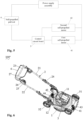
- the disclosure provides a self-propelled lawn mower 100.
- the lawn mower 100 includes a housing 1, a push rod 2 connected to the housing 1, a traveling wheel supported the lawn mower 100, a self-propelled motor which is configured to drive the traveling wheel to self-propel, a control circuit board 5 which is configured to control turning-on and turning-off of the self-propelled motor and an enclosure which is assembled with the housing 1 (not shown).
- a blade and a motor for driving the blade to rotate are arranged in the housing 1, a power assembly 11 is formed by the blade and the motor.
- the blade arranged at the bottom of the housing 1 is rotatable along a rotating shaft perpendicular to a ground to mow grasses on the ground.
- a power supply assembly (not shown) is also arranged in the housing 1, and the power supply assembly is configured to supply power to the lawn mower 100 to ensure that the grasses are mowed effectively.
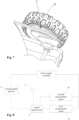
- the push rod 2 is U-shaped and include a first handle 21, a second handle 22, and a third handle 23.
- the first handle 21 extends backward and upward along a rear portion of the housing 1
- the third handle 23 is connected with the first handle 21 and the second handle 22, and the third handle 23 is located at the top of the push rod 2, such that an operator may stand behind the push rod 2 and grasp the third handle 23 of the push rod 2 to thereby operate the lawn mower 100.
- the first handle 21, the second handle 22 and the third handle 23 may be integrally formed, and may also be assembled and connected, which is not limited herein, as long as it is convenient to operate the lawn mower 100.
- the first handle 21 and the second handle 22 are each provided with a folding structure 24, and the folding structure 24 is configured to adjust an angle of the push rod 2, thereby facilitating folding of the lawn mower 100.
- the housing 1 is also provided with a height adjustment assembly 12 for adjusting a height between the housing 1 and the ground to thereby adjust a mowing height.
- a main knife switch box 25 is arranged a position on the second handle 22 close to the third handle 23.
- a turning-on switch (not shown), a turning-on button 26 and a return spring (not shown) are arranged in the main knife switch box 25.
- the turning-on switch is connected with the motor for turning-on the motor.
- the lawn mower 100 further includes a main knife switch pull rod 27 arranged close to the third handle 23, and the main knife switch pull rod 27 is arranged above the main knife switch box 25 and connected with the turning-on switch.
- the turning-on button 26 is first pressed, the main knife switch pull rod 27 is then pulled to thereby enable the main knife switch pull rod 27 to fit with the third handle 23, enable the main knife switch pull rod 27 to pull the turning-on switch to turn-on the motor and drive the blade to rotate for performing a mowing process.
- the main knife switch pull rod 27 is released, and the main knife switch pull rod 27 is restored to an initial position under the action of the return spring, and then the turning-on switch is turned-off and the blade stops rotating.
- the traveling wheel includes a pair of front traveling wheels 31 and a pair of rear traveling wheels 32.
- the self-propelled motor includes a first self-propelled motor 41 and a second self-propelled motor 42.
- the first self-propelled motor 41 is configured to drive the front traveling wheels 31 to self-propel.
- the second self-propelled motor 42 is configured to drive the rear traveling wheels 32 to self-propel.
- the first self-propelled motor 41 and the second self-propelled motor 42 are powered by the power supply assembly and electrically connected with the control circuit board 5 respectively.
- control circuit board 5 is a printed circuit board (PCB), and the first self-propelled motor 41 and the second self-propelled motor 42 are electrically connected to the PCB respectively, so that the turning-on and turning-off of the first self-propelled motor 41 and the second self-propelled motor 42 are controlled by the PCB.
- PCB printed circuit board
- first self-propelled motor 41 is configured to drive the front traveling wheels 31 to self-propel
- second self-propelled motor 42 is configured to drive the rear traveling wheels 32 to self-propel in the embodiment.
- first self-propelled motor 41 can also be configured to drive the rear traveling wheels 32 to self-propel
- the second self-propelled motor 42 can be configured to drive the front traveling wheels 31 to self-propel, which is not limited herein.
- the lawn mower 100 further includes a first speed reducing mechanism 43 connected with the first self-propelled motor 41 and a second speed reducing mechanism 44 connected with the second self-propelled motor 42. Clutches (not shown) are arranged in each of the first speed reducing mechanism 43 and the second speed reducing mechanism 44.
- the clutch of the first speed reducing mechanism 43 is configured to enable an output shaft of the first speed reducing mechanism 43 not to contact with a wheel shaft of each front traveling wheel 31 if the first self-propelled motor 41 is out of service
- the clutch of the second speed reducing mechanism 44 is configured to enable an output shaft of the second speed reducing mechanism 44 not to contact with a wheel shaft of each rear traveling wheel 32 if the second self-propelled motor 42 is out of service.
- the first self-propelled motor 41 and/or the second self-propelled motor 42 are/is in a turned-off state, even if the lawn mower 100 is in moving state, the first self-propelled motor 41 and/or the second self-propelled motor 42 will not be reversely driven by the front traveling wheels 31 and/or the rear traveling wheels 32.
- the clutch is common in a prior art, and a specific structure and a power principle thereof may be referred to a patent application No. CN201721623687.X , it will not be described in detail herein.
- the first speed reducing mechanism 43 is arranged close to the first self-propelled motor 41, each of the first speed reducing mechanism 43 and the first self-propelled motor 41 is arranged close to the front traveling wheels 31.
- the second speed reducing mechanism 44 is arranged close to the second self-propelled motor 42, each of the second speed reducing mechanism 44 and the second self-propelled motor 42 is arranged close to the rear traveling wheels 32.
- the lawn mower 100 further includes a first control element and a second control element.
- the first control element is connected with the control circuit board 5 and configured to control the control circuit board 5 to turn-on or turn-off the first self-propelled motor 41
- the second control element is configured to control the control circuit board 5 to turn-on or turn-off the second self-propelled motor 42.
- the first control element is a self-propelled pull rod 6, which is arranged close to the top of the push rod 2 and the third handle 23.
- the first self-propelled motor 41 is turned-on, if the self-propelled pull rod 6 is pulled so as to fit the third handle 23.
- the self-propelled pull rod 6 returns to an initial position thereof and the first self-propelled motor 41 is turned-off, if the self-propelled pull rod 6 is released.
- additional actions can be performed besides pulling the self-propelled pull rod 6 to realize the turning-on and turning-off of the first self-propelled motor 41.
- the main knife switch pull rod 27 is arranged on a side of the third handle 23, and the self-propelled pull rod 6 is arranged on the other side of the third handle 23. With this arrangement, when the lawn mower 100 is turned-on, the main knife switch pull rod 27 and the self-propelled pull rod 6 is simultaneously pulled to fit with the third handle 23, thereby facilitating grasping of the main knife switch pull rod 27 and the self-propelled pull rod 6 by the operator.
- the second control element is a push button 7 arranged close to the top of the push rod 2, which is connected with the control circuit board 5.
- the control circuit board 5 is controlled to correspondingly turn-on or turn-off the second self-propelled motor 42.
- the first handle 21 is provided with a self-propelled switch box 28, and the push button 7 is disposed on the self-propelled switch box 28.
- the control circuit board 5 controls the second self-propelled motor 42 to power on and thereby controls the turning-on of the second self-propelled motor 42.
- the control circuit board 5 controls the second self-propelled motor 42 to turn-off and thereby controls the turning-off of the second self-propelled motor 42.
- the self-propelled pull rod 6 when the lawn mower 100 is traveling, the self-propelled pull rod 6 is pulled to enable the self-propelled pull rod 6 to fit with the third handle 23, in this case, the first self-propelled motor 41 is turned-on to drive the front traveling wheels 31 to self-propel through the first speed reducing mechanism 43, and the second self-propelled motor 42 is in a standby state.
- the premise that the second self-propelled motor 42 can be turned-on is that the first self-propelled motor 41 is in a turned-on state. That is to say, when the first self-propelled motor 41 is turned-off, the second self-propelled motor 42 will not be turned-on even if the push button 7 is in a turning-on state.
- the operations of the first self-propelled motor 41 and the second self-propelled motor 42 may be independent of each other.
- the operation requirements can be met if the two front traveling wheels 31 are driven merely by the first self-propelled motor 41 to self-propel.
- the push button 7 is required to be pushed, so as to turn-on the second self-propelled motor 42 to thereby drive the rear traveling wheels 32 to self-propel through the second reducing mechanism 44, thereby realizing four-wheel drive.
- the second self-propelled motor 42 may be turned-off by using the push button 7, thereby effectively saving electric energy and prolonging the endurance of the lawn mower 100.
- the operator may turn-off (i.e., release) the self-propelled pull rod 6 to turn off the first self-propelled motor 41 to further save electric energy.
- the second control element is a detection module (not shown), which is arranged on the control circuit board 5 and configured to detect a power of the first self-propelled motor 41, comparing the power with a set value to determine whether the second self-propelled motor 42 needs to be turned-on or turned-off.
- the power of the first self-propelled motor 41 can be calculated by the detection module according to a current of the first self-propelled motor 41 detected by the detection module. Further, the detection module transmits the calculated power of the first self-propelled motor 41 to the control circuit board 5, and then the control circuit board 5 controls the second self-propelled motor 42 to turn-on or turn-off according to the received power of the first self-propelled motor 41.
- control circuit board 5 controls the second self-propelled motor 42 to turn-on when the power of the first self-propelled motor 41 is higher than an upper limit of the set value, while the control circuit board 5 may control the second self-propelled motor 42 to turn-off when the power of the first self-propelled motor 41 is smaller than a lower limit of the set value.
- the upper limit of the set value may be in a range from 300 Watts (W) to 350 W, and preferably 320 W.
- the lower limit of the set value may be in a range from 200 W to 250 W, and preferably 240 W.
- the self-propelled pull rod 6 when the lawn mower 100' is traveling, the self-propelled pull rod 6 is pulled to enable the self-propelled pull rod 6 to fit with the third handle 23, in this case, the first self-propelled motor 41 is turned-on to drive the front traveling wheels 31 to self-propel through the first speed reducing mechanism 43, and the second self-propelled motor 42 is in a standby state.
- the power of the first self-propelled motor 41 is small due to a small resistance, therefore, the operation requirements can be met if the two front traveling wheels 31 are driven merely by the first self-propelled motor 41 to self-propel.
- a self-propelled load of the lawn mower 100' is large.
- the detection module detects that the power of the first self-propelled motor 41 is large and exceeds the upper limit of the set value, the second self-propelled motor 42 is turned-on to drive the rear traveling wheels 32 to self-propel through the second speed reducing mechanism 44, thereby realizing four-wheel drive, in turn, reducing a running power of the first self-propelled motor 41 and avoiding overload of the first self-propelled motor 41.
- the self-propelled load of the lawn mower 100' is small due to a small resistance.
- the detection module detects that the power of the first self-propelled motor 41 is small and smaller than the lower limit of the set value, the second self-propelled motor 42 is turned-off to enable the efficiency of the first self-propelled motor 41 in a better state.
- the operator may turn-off (i.e., release) the self-propelled pull rod 6 to turn-off the first self-propelled motor 41, thereby saving electric energy and prolonging the endurance of the lawn mower 100'.
- the second control element is an angular velocity sensor 7', which is arranged on the wheel shaft of each of the front traveling wheels 31 or the rear traveling wheels 32 and configured to transmit current angular velocity information of the corresponding traveling wheel to the control circuit board 5 in real time, and the control circuit board 5 determines whether the second self-propelled motor 42 needs to be turned-on or turned-off according to the received angular velocity information.
- the control circuit board 5 can calculate a current traveling speed of the lawn mower 100" according to the angular velocity information of the traveling wheels, compare the current traveling speed with a set value. Specifically, if the current traveling speed of the lawn mower 100" is smaller than a lower limit of a set value, the control circuit board 5 controls the second self-propelled motor 42 to turn-on; while if the current traveling speed of the lawn mower 100" is higher than an upper limit of the set value, the control circuit board 5 controls the second self-propelled motor 42 to turn-off.
- the upper limit of the set value is in a range from 1.4 meters per second (m/s) to 2 m/s, and preferably 1.5 m/s;
- the lower limit of the set value is in a range from 0 to 1 m/s, preferably 0.5 m/s.
- the self-propelled pull rod 6 when the lawn mower 100" is traveling, the self-propelled pull rod 6 is pulled to enable the self-propelled pull rod 6 to fit with the third handle 23, in this case, the first self-propelled motor 41 is turned-on to drive the front traveling wheels 31 to self-propel through the first speed reducing mechanism 43, and the second self-propelled motor 42 is in a standby state.
- the traveling speed of the lawn mower 100" is reduced.
- the control circuit board 5 calculates that the traveling speed of the lawn mower 100" is reduced and smaller than the lower limit of the set value, the second self-propelled motor 42 is turned-on to drive the rear traveling wheels 32 to self-propel through the second deceleration mechanism 44, thereby realizing four-wheel drive, and enabling the traveling speed of the lawn mower 100" at a normal level.
- a self-propelled speed of the lawn mower 100" is accelerated due to a small resistance.
- the control circuit board 5 calculates that the traveling speed of the lawn mower 100" is faster and higher than the upper limit of the set value, the second self-propelled motor 42 is turned-off to enable the traveling speed of the lawn mower 100" at the normal level. Further, if the self-propelled speed of the lawn mower 100 "is still too high in this case, the operator may turn-off (i.e., release) the self-propelled pull rod 6 to turn-off the first self-propelled motor 41, thereby saving electric energy and prolonging the endurance of the lawn mower 100".
- the following conclusions can be drawn.
- the operation requirements can be met by driving a single self-propelled motor, only the first self-propelled motor 41 operates to realize the self-propelled of the two front traveling wheels 31; while when the operation requirements cannot be met by driving a single self-propelled motor, the second self-propelled motor 42 further operates to realize four-wheel drive.
- the first self-propelled motor 41 and the second self-propelled motor 42 may be separately controlled, therefore, the effect of saving energy is not only achieved, but it is also convenient for operation and maintenance.
- the enclosure may snap-fit with the housing 1, and is configured to cover the housing 1, the power assembly 11, the first self-propelled motor 41, the second self-propelled motor 42, the control circuit board 5 and the like, so as to prevent the power assembly, the power assembly 11, the first self-propelled motor 41, the second self-propelled motor 42 and the control circuit board 5 from being damaged by dust, water stains, etc., and to ensure that the lawn mowers 100, 100' and 100" can operate safely and stably, thereby prolonging the service life of the lawn mowers 100, 100' and 100".
- the first control element is set to control the turning-on or turning-off of the first self-propelled motor 41
- the second control element is set to control the turning-on or turning-off of the second self-propelled motor 42, such that when the operation requirements can be met by driving a single self-propelled motor, only the first self-propelled motor 41 is controlled to operate so as to realize two-wheel drive; while when the operation requirements cannot be met by driving a single self-propelled motor, the second self-propelled motor 42 may be further controlled to operate to realize four-wheel drive.
- the first self-propelled motor 41 and the second self-propelled motor 42 may be separately controlled, therefore, the effect of saving energy is not only achieved, but it is also convenient for operation and maintenance.
Landscapes
- Life Sciences & Earth Sciences (AREA)
- Environmental Sciences (AREA)
- Harvester Elements (AREA)
- Rehabilitation Tools (AREA)
Claims (15)
- Rasenmäher (100), umfassend:ein Gehäuse (1);eine mit dem Gehäuse (1) verbundene Schubstange (2);ein Laufrad zum Tragen des Rasenmähers (100);einen selbst getriebenen Motor zum Antreiben des Laufrads, um sich selbst anzutreiben; undeine Steuerplatine (5) zum Steuern von Ein- und Ausschalten des selbst getriebenen Motors;wobei das Laufrad ein Paar vordere Laufräder (31) und ein Paar hintere Laufräder (32) umfasst,dadurch gekennzeichnet, dassder selbst getriebene Motor einen ersten selbst getriebenen Motor (41) umfasst, der konfiguriert ist, um die vorderen Laufräder (31) anzutreiben, um sich selbst anzutreiben, und einen zweiten selbst getriebenen Motor (42), der konfiguriert ist, um die hinteren Laufräder (32) anzutreiben, um sich selbst anzutreiben, wobei der Rasenmäher (100) weiter ein erstes Steuerelement und ein zweites Steuerelement umfasst, wobei das erste Steuerelement konfiguriert ist, um die Steuerplatine (5) zu steuern, um den ersten selbst getriebenen Motor (41) ein- oder auszuschalten, und das zweite Steuerelement konfiguriert ist, um die Steuerplatine (5) zu steuern, um den zweiten selbst getriebenen Motor (42) ein- oder auszuschalten.
- Rasenmäher (100) nach Anspruch 1, wobei die Schubstange (2) U-förmig ist und einen ersten Griff (21), einen zweiten Griff (22) und einen dritten Griff (23) umfasst, wobei sich der erste (21) und der zweite Griff (22) entlang eines hinteren Abschnitts des Gehäuses (1) nach hinten und oben erstrecken und der dritte Griff (23) mit dem ersten Griff (21) und dem zweiten Griff (22) verbunden ist und sich an der Oberseite der Schubstange (2) befindet.
- Rasenmäher (100) nach Anspruch 2, wobei das erste Steuerelement eine selbst getriebene Zugstange (6) ist, die in der Nähe des dritten Griffs (23) angeordnet ist, wobei der erste selbst getriebene Motor eingeschaltet wird, wenn die selbst getriebene Zugstange (6) gezogen wird, um die selbst getriebene Zugstange (6) in den dritten Griff (23) zu passen, und wobei der erste selbst getriebene Motor (41) ausgeschaltet wird, wenn die selbst getriebene Zugstange (6) losgelassen wird, um der selbst getriebenen Zugstange (6) zu ermöglichen, eine Ausgangsposition wiederherzustellen.
- Rasenmäher (100) nach Anspruch 1, wobei das zweite Steuerelement ein Druckknopf (7) ist, der in der Nähe der Oberseite der Schubstange (2) angeordnet ist, wobei der Druckknopf (7) mit der Steuerplatine (5) verbunden ist und die Steuerplatine (5) gesteuert wird, um den zweiten selbst getriebenen Motor (42) in einem Fall ein- oder auszuschalten, dass der Druckknopf (7) gedrückt wird.
- Rasenmäher (100) nach Anspruch 4, wobei ein selbst getriebener Schaltkasten (28) an der Schubstange (2) angeordnet ist und der Druckknopf (7) an dem selbst getriebenen Schaltkasten (28) angeordnet ist.
- Rasenmäher (100) nach Anspruch 1, wobei das zweite Steuerelement auf der Steuerplatine (5) angeordnet und konfiguriert ist, um eine Leistung des ersten selbst getriebenen Motors (41) zu erfassen und die Leistung mit einem Sollwert zu vergleichen; und die Steuerplatine (5) konfiguriert ist, um den zweiten selbst getriebenen Motor (42) zu steuern, um sich einzuschalten, wenn die Leistung des ersten selbst getriebenen Motors (41) höher ist als eine Obergrenze des Sollwerts, und den zweiten selbst getriebenen Motor (42) zu steuern, um sich auszuschalten, wenn die Leistung des ersten selbst getriebenen Motors (41) kleiner ist als die Untergrenze des Sollwerts.
- Rasenmäher (100) nach Anspruch 6, wobei die Obergrenze des Sollwerts in einem Bereich von 300 W bis 350 W liegt und die Untergrenze des Sollwerts in einem Bereich von 200 W bis 250 W liegt.
- Rasenmäher (100) nach Anspruch 6, wobei die Leistung des ersten selbst getriebenen Motors (41) durch das zweite Steuerelement entsprechend einem durch das zweite Steuerelement erfassten Strom des ersten selbst getriebenen Motors (41) berechnet wird.
- Rasenmäher (100) nach Anspruch 1, wobei das zweite Steuerelement ein Winkelgeschwindigkeitssensor (7') ist, der an einer Radwelle des Laufrads angeordnet ist, und der Winkelgeschwindigkeitssensor (7') konfiguriert ist, um aktuelle Winkelgeschwindigkeitsinformationen des Laufrads an die Steuerplatine (5) zu übertragen, sodass die Steuerplatine (5) Ein- oder Ausschalten des zweiten selbst getriebenen Motors (42) entsprechend den empfangenen Winkelgeschwindigkeitsinformationen ermöglicht.
- Rasenmäher (100) nach Anspruch 9, wobei die Steuerplatine (5) konfiguriert ist, um: eine aktuelle Fahrgeschwindigkeit des Rasenmähers (100) entsprechend den empfangenen Winkelgeschwindigkeitsinformationen zu berechnen; die aktuelle Fahrgeschwindigkeit mit einem Sollwert zu vergleichen; den zweiten selbst getriebenen Motor (42) zu steuern, um sich einzuschalten, wenn die aktuelle Fahrgeschwindigkeit des Rasenmähers kleiner als eine Untergrenze des Sollwerts ist, und den zweiten selbst getriebenen Motor (42) zu steuern, um sich auszuschalten, wenn die aktuelle Fahrgeschwindigkeit des Rasenmähers größer als eine Obergrenze des Sollwerts ist.
- Rasenmäher (100) nach Anspruch 10, wobei die Obergrenze des Sollwerts in einem Bereich von 1,4 m/s bis 2 m/s liegt und die Untergrenze des Sollwerts in einem Bereich von 0 bis 1 m/s liegt.
- Rasenmäher (100) nach Anspruch 11, wobei die Obergrenze des Sollwerts 1,5 m/s beträgt und die untere Grenze des Sollwerts 0,5 m/s beträgt.
- Rasenmäher (100) nach Anspruch 1, wobei der Rasenmäher (100) weiter einen ersten Geschwindigkeitsreduzierungsmechanismus (43) umfasst, der mit dem ersten selbst getriebenen Motor (41) verbunden ist, und einen zweiten Geschwindigkeitsreduzierungsmechanismus (44), der mit dem zweiten selbst getriebenen Motor (42) verbunden ist, und eine Kupplung in jedem von dem ersten Geschwindigkeitsreduzierungsmechanismus (43) und dem zweiten Geschwindigkeitsreduzierungsmechanismus (44) angeordnet ist.
- Rasenmäher (100) nach Anspruch 1, wobei die Steuerplatine (5) eine gedruckte Leiterplatte, PCB, ist und der erste selbst getriebene Motor (41) und der zweite selbst getriebene Motor (42) jeweils elektrisch mit der PCB verbunden sind.
- Rasenmäher (100) nach Anspruch 1, wobei der Rasenmäher (100) weiter eine an dem Gehäuse (1) angeordnete Leistungsversorgungsbaugruppe umfasst und der erste selbst getriebene Motor (41) und der zweite selbst getriebene Motor (42) durch die Leistungsversorgungsbaugruppe mit Leistung versorgt werden.
Applications Claiming Priority (2)
| Application Number | Priority Date | Filing Date | Title |
|---|---|---|---|
| CN201811172312 | 2018-10-09 | ||
| PCT/CN2019/111715 WO2020074011A1 (zh) | 2018-10-09 | 2019-10-17 | 推草机 |
Publications (4)
| Publication Number | Publication Date |
|---|---|
| EP3864950A1 EP3864950A1 (de) | 2021-08-18 |
| EP3864950A4 EP3864950A4 (de) | 2021-12-08 |
| EP3864950C0 EP3864950C0 (de) | 2025-05-28 |
| EP3864950B1 true EP3864950B1 (de) | 2025-05-28 |
Family
ID=65468802
Family Applications (1)
| Application Number | Title | Priority Date | Filing Date |
|---|---|---|---|
| EP19870559.2A Active EP3864950B1 (de) | 2018-10-09 | 2019-10-17 | Schieberasenmäher |
Country Status (4)
| Country | Link |
|---|---|
| US (3) | US12069983B2 (de) |
| EP (1) | EP3864950B1 (de) |
| CN (1) | CN109392418A (de) |
| WO (1) | WO2020074011A1 (de) |
Families Citing this family (14)
| Publication number | Priority date | Publication date | Assignee | Title |
|---|---|---|---|---|
| US9888627B2 (en) | 2012-10-15 | 2018-02-13 | Chervon (Hk) Limited | Lawncare apparatus with a foldable operating arm |
| US9596806B2 (en) | 2013-10-10 | 2017-03-21 | Chervon (Hk) Limited | Control system for controlling the operation of a gardening tool |
| US11606900B2 (en) | 2012-10-15 | 2023-03-21 | Chervon (Hk) Limited | Gardening tool |
| CN109392418A (zh) * | 2018-10-09 | 2019-03-01 | 常州格力博有限公司 | 推草机 |
| CN109392467B (zh) * | 2018-12-14 | 2024-01-02 | 格力博(江苏)股份有限公司 | 园林工具 |
| WO2020178959A1 (ja) * | 2019-03-04 | 2020-09-10 | 本田技研工業株式会社 | 作業機 |
| CN115245087B (zh) * | 2021-04-27 | 2024-04-30 | 南京泉峰科技有限公司 | 后走式自推工作机 |
| US11638397B2 (en) | 2020-02-10 | 2023-05-02 | Techtronic Cordless Gp | Control assembly coupled to handle of an implement |
| CN115316107B (zh) * | 2022-07-26 | 2024-05-17 | 利欧集团浙江泵业有限公司 | 一种草坪机开关盒 |
| US20240206385A1 (en) * | 2022-12-27 | 2024-06-27 | Nanjing Chervon Industry Co., Ltd. | Rear-moving power tool |
| USD1118704S1 (en) * | 2023-06-16 | 2026-03-17 | Andreas Stihl Ag & Co. Kg | Lawnmower |
| USD1117354S1 (en) * | 2023-06-16 | 2026-03-10 | Andreas Stihl Ag & Co. Kg | Lawnmower |
| USD1120032S1 (en) * | 2023-06-16 | 2026-03-24 | Andreas Stihl Ag & Co. Kg | Lawnmower |
| USD1117355S1 (en) * | 2023-12-22 | 2026-03-10 | Andreas Stihl Ag & Co. Kg | Lawnmower |
Family Cites Families (36)
| Publication number | Priority date | Publication date | Assignee | Title |
|---|---|---|---|---|
| US2879074A (en) * | 1956-10-29 | 1959-03-24 | Roberton Mfg Co | Wheel adjustment for mowers |
| JPH0614B2 (ja) * | 1986-11-10 | 1994-01-05 | 株式会社クボタ | 歩行型芝刈り機の走行用伝動構造 |
| US5507138A (en) * | 1994-12-16 | 1996-04-16 | Wright Manufacturing Inc. | Power mower with riding platform for supporting standing-operator |
| US6591593B1 (en) | 2000-10-23 | 2003-07-15 | Dennis Brandon | Electric riding lawn mower powered by an internal combustion engine and generator system |
| JP2007050745A (ja) * | 2005-08-17 | 2007-03-01 | Kanzaki Kokyukoki Mfg Co Ltd | 油圧駆動式車輌 |
| JP2007186174A (ja) * | 2006-01-16 | 2007-07-26 | Kanzaki Kokyukoki Mfg Co Ltd | 走行用油圧式無段変速装置 |
| JP4886556B2 (ja) * | 2007-03-08 | 2012-02-29 | 株式会社共栄社 | 全車輪油圧駆動乗用芝刈機 |
| US8429885B2 (en) * | 2008-04-25 | 2013-04-30 | Black & Decker Inc. | Cordless mower including cooling air flow arrangement |
| KR101762479B1 (ko) * | 2014-03-10 | 2017-07-27 | 가부시끼 가이샤 구보다 | 예초기 |
| CN204037368U (zh) * | 2014-07-25 | 2014-12-24 | 刘海湘 | 一种双驱动高续航电动车 |
| JP6193898B2 (ja) * | 2015-02-10 | 2017-09-06 | 本田技研工業株式会社 | 自律走行作業車の制御装置 |
| CN204547726U (zh) * | 2015-04-15 | 2015-08-12 | 江苏理工学院 | 双驱动电动汽车动力系统 |
| FR3039355B1 (fr) * | 2015-07-27 | 2017-07-14 | Pellenc Sa | Tondeuse electrique a lames multiples |
| CN205239188U (zh) * | 2015-12-03 | 2016-05-18 | 康迪电动汽车(长兴)有限公司 | 一种电动汽车驱动装置 |
| CN205510937U (zh) * | 2015-12-29 | 2016-08-31 | 常州格力博有限公司 | 一种驱动装置及适配该驱动装置的割草机 |
| CN105960950B (zh) * | 2015-12-29 | 2019-06-18 | 常州格力博有限公司 | 一种割草机 |
| CN107371562B (zh) * | 2016-05-16 | 2020-07-17 | 南京德朔实业有限公司 | 动力工具、割草机及其控制方法 |
| CN206042821U (zh) * | 2016-06-14 | 2017-03-29 | 常州格力博有限公司 | 控制面板及其推草机 |
| US10039229B2 (en) * | 2016-06-28 | 2018-08-07 | The Toro Company | Walk power mower having forward and reverse traction drive |
| US10111381B2 (en) * | 2016-06-28 | 2018-10-30 | The Toro Company | Walk power mower with transmission providing both forward and reverse propulsion |
| CN206264775U (zh) * | 2016-07-22 | 2017-06-20 | 淄博舜泰电动汽车有限公司 | 一种电动汽车双动力输出系统 |
| CN205993119U (zh) * | 2016-08-03 | 2017-03-08 | 安志辉 | 一种四轮驱动的遥控割草机 |
| CN108323305B (zh) * | 2017-01-19 | 2024-11-08 | 苏州科瓴精密机械科技有限公司 | 自动行走机器人 |
| EP3574742B1 (de) * | 2017-01-25 | 2022-11-16 | Positec Power Tools (Suzhou) Co., Ltd | Rasenmäher |
| CN107323452B (zh) * | 2017-06-08 | 2018-06-08 | 深圳市海梁科技有限公司 | 混合动力车辆及其驱动控制方法 |
| CN207522533U (zh) * | 2017-06-14 | 2018-06-22 | 常州格力博有限公司 | 控制组件及动力工具 |
| CN109747698B (zh) * | 2017-11-08 | 2020-05-26 | 南京德朔实业有限公司 | 手推式自驱行进机器 |
| CN207594712U (zh) | 2017-11-29 | 2018-07-10 | 常州格力博有限公司 | 自走动力系统 |
| US11714411B2 (en) * | 2018-03-19 | 2023-08-01 | Honda Motor Co., Ltd. | Autonomous traveling work machine |
| CN108243709B (zh) * | 2018-03-29 | 2020-04-03 | 湖北益通建设股份有限公司 | 一种园林用手推式割草机 |
| CN108496521A (zh) * | 2018-04-20 | 2018-09-07 | 成都汇美园林景观有限公司 | 一种基于太阳能供电的四轮智能草坪收割机 |
| CN108513790A (zh) * | 2018-07-02 | 2018-09-11 | 浙江中马园林机器股份有限公司 | 一种割草机的多功能手柄以及具有该手柄的割草机 |
| CN208972006U (zh) * | 2018-10-09 | 2019-06-14 | 常州格力博有限公司 | 推草机 |
| CN208972005U (zh) * | 2018-10-09 | 2019-06-14 | 常州格力博有限公司 | 推草机 |
| CN109392418A (zh) * | 2018-10-09 | 2019-03-01 | 常州格力博有限公司 | 推草机 |
| CN208971999U (zh) * | 2018-10-09 | 2019-06-14 | 常州格力博有限公司 | 推草机 |
-
2018
- 2018-10-23 CN CN201811234727.0A patent/CN109392418A/zh active Pending
-
2019
- 2019-10-17 EP EP19870559.2A patent/EP3864950B1/de active Active
- 2019-10-17 WO PCT/CN2019/111715 patent/WO2020074011A1/zh not_active Ceased
- 2019-10-17 US US17/283,248 patent/US12069983B2/en active Active
-
2024
- 2024-07-25 US US18/783,488 patent/US12376516B2/en active Active
-
2025
- 2025-07-11 US US19/266,220 patent/US20250338793A1/en active Pending
Also Published As
| Publication number | Publication date |
|---|---|
| US20210337727A1 (en) | 2021-11-04 |
| WO2020074011A1 (zh) | 2020-04-16 |
| US20250338793A1 (en) | 2025-11-06 |
| EP3864950A4 (de) | 2021-12-08 |
| EP3864950C0 (de) | 2025-05-28 |
| US12069983B2 (en) | 2024-08-27 |
| CN109392418A (zh) | 2019-03-01 |
| US20240397858A1 (en) | 2024-12-05 |
| EP3864950A1 (de) | 2021-08-18 |
| US12376516B2 (en) | 2025-08-05 |
Similar Documents
| Publication | Publication Date | Title |
|---|---|---|
| EP3864950B1 (de) | Schieberasenmäher | |
| US5502957A (en) | Electric lawn mower with intelligent control | |
| US11317564B2 (en) | Electric mower apparatus and method of use | |
| EP2720526B1 (de) | Drehzahlsteuerung für elektrowerkzeuge | |
| CN109076773B (zh) | 电动手扶式草地用割草机 | |
| CN107371562B (zh) | 动力工具、割草机及其控制方法 | |
| US7728534B2 (en) | Hybrid electric lawnmower | |
| CN101861781B (zh) | 自驱式割草机 | |
| EP3586594B1 (de) | Handgeführtes, elektrisches gartengerät | |
| EP3574742A1 (de) | Rasenmäher | |
| GB2303719A (en) | Control device for an electric motor | |
| JPH09201126A (ja) | 電動芝刈機 | |
| WO2019238099A1 (zh) | 自移动设备 | |
| CN208972006U (zh) | 推草机 | |
| CN208971999U (zh) | 推草机 | |
| CN211831924U (zh) | 一种全向割草机 | |
| CN112796267A (zh) | 手推式电动工具及其转向操作方法 | |
| CN208972005U (zh) | 推草机 | |
| EP3818806B1 (de) | Gartenwerkzeug | |
| CN211353022U (zh) | 一种园林工具 | |
| CN113873870A (zh) | 多刀片割草机 |
Legal Events
| Date | Code | Title | Description |
|---|---|---|---|
| STAA | Information on the status of an ep patent application or granted ep patent |
Free format text: STATUS: THE INTERNATIONAL PUBLICATION HAS BEEN MADE |
|
| PUAI | Public reference made under article 153(3) epc to a published international application that has entered the european phase |
Free format text: ORIGINAL CODE: 0009012 |
|
| STAA | Information on the status of an ep patent application or granted ep patent |
Free format text: STATUS: REQUEST FOR EXAMINATION WAS MADE |
|
| 17P | Request for examination filed |
Effective date: 20210430 |
|
| AK | Designated contracting states |
Kind code of ref document: A1 Designated state(s): AL AT BE BG CH CY CZ DE DK EE ES FI FR GB GR HR HU IE IS IT LI LT LU LV MC MK MT NL NO PL PT RO RS SE SI SK SM TR |
|
| A4 | Supplementary search report drawn up and despatched |
Effective date: 20211108 |
|
| RIC1 | Information provided on ipc code assigned before grant |
Ipc: A01D 34/69 20060101ALI20211102BHEP Ipc: A01D 34/68 20060101AFI20211102BHEP |
|
| DAV | Request for validation of the european patent (deleted) | ||
| DAX | Request for extension of the european patent (deleted) | ||
| GRAP | Despatch of communication of intention to grant a patent |
Free format text: ORIGINAL CODE: EPIDOSNIGR1 |
|
| STAA | Information on the status of an ep patent application or granted ep patent |
Free format text: STATUS: GRANT OF PATENT IS INTENDED |
|
| RIC1 | Information provided on ipc code assigned before grant |
Ipc: A01D 34/69 20060101ALI20241128BHEP Ipc: A01D 34/68 20060101AFI20241128BHEP |
|
| INTG | Intention to grant announced |
Effective date: 20241220 |
|
| GRAS | Grant fee paid |
Free format text: ORIGINAL CODE: EPIDOSNIGR3 |
|
| GRAA | (expected) grant |
Free format text: ORIGINAL CODE: 0009210 |
|
| STAA | Information on the status of an ep patent application or granted ep patent |
Free format text: STATUS: THE PATENT HAS BEEN GRANTED |
|
| AK | Designated contracting states |
Kind code of ref document: B1 Designated state(s): AL AT BE BG CH CY CZ DE DK EE ES FI FR GB GR HR HU IE IS IT LI LT LU LV MC MK MT NL NO PL PT RO RS SE SI SK SM TR |
|
| REG | Reference to a national code |
Ref country code: GB Ref legal event code: FG4D |
|
| REG | Reference to a national code |
Ref country code: CH Ref legal event code: EP |
|
| REG | Reference to a national code |
Ref country code: IE Ref legal event code: FG4D Ref country code: DE Ref legal event code: R096 Ref document number: 602019070618 Country of ref document: DE |
|
| U01 | Request for unitary effect filed |
Effective date: 20250528 |
|
| U07 | Unitary effect registered |
Designated state(s): AT BE BG DE DK EE FI FR IT LT LU LV MT NL PT RO SE SI Effective date: 20250605 |
|
| PG25 | Lapsed in a contracting state [announced via postgrant information from national office to epo] |
Ref country code: ES Free format text: LAPSE BECAUSE OF FAILURE TO SUBMIT A TRANSLATION OF THE DESCRIPTION OR TO PAY THE FEE WITHIN THE PRESCRIBED TIME-LIMIT Effective date: 20250528 |
|
| PG25 | Lapsed in a contracting state [announced via postgrant information from national office to epo] |
Ref country code: NO Free format text: LAPSE BECAUSE OF FAILURE TO SUBMIT A TRANSLATION OF THE DESCRIPTION OR TO PAY THE FEE WITHIN THE PRESCRIBED TIME-LIMIT Effective date: 20250828 Ref country code: GR Free format text: LAPSE BECAUSE OF FAILURE TO SUBMIT A TRANSLATION OF THE DESCRIPTION OR TO PAY THE FEE WITHIN THE PRESCRIBED TIME-LIMIT Effective date: 20250829 |
|
| PG25 | Lapsed in a contracting state [announced via postgrant information from national office to epo] |
Ref country code: PL Free format text: LAPSE BECAUSE OF FAILURE TO SUBMIT A TRANSLATION OF THE DESCRIPTION OR TO PAY THE FEE WITHIN THE PRESCRIBED TIME-LIMIT Effective date: 20250528 |
|
| PG25 | Lapsed in a contracting state [announced via postgrant information from national office to epo] |
Ref country code: HR Free format text: LAPSE BECAUSE OF FAILURE TO SUBMIT A TRANSLATION OF THE DESCRIPTION OR TO PAY THE FEE WITHIN THE PRESCRIBED TIME-LIMIT Effective date: 20250528 |
|
| PG25 | Lapsed in a contracting state [announced via postgrant information from national office to epo] |
Ref country code: RS Free format text: LAPSE BECAUSE OF FAILURE TO SUBMIT A TRANSLATION OF THE DESCRIPTION OR TO PAY THE FEE WITHIN THE PRESCRIBED TIME-LIMIT Effective date: 20250828 |
|
| PG25 | Lapsed in a contracting state [announced via postgrant information from national office to epo] |
Ref country code: IS Free format text: LAPSE BECAUSE OF FAILURE TO SUBMIT A TRANSLATION OF THE DESCRIPTION OR TO PAY THE FEE WITHIN THE PRESCRIBED TIME-LIMIT Effective date: 20250928 |
|
| U20 | Renewal fee for the european patent with unitary effect paid |
Year of fee payment: 7 Effective date: 20251027 |
|
| PG25 | Lapsed in a contracting state [announced via postgrant information from national office to epo] |
Ref country code: SM Free format text: LAPSE BECAUSE OF FAILURE TO SUBMIT A TRANSLATION OF THE DESCRIPTION OR TO PAY THE FEE WITHIN THE PRESCRIBED TIME-LIMIT Effective date: 20250528 |
|
| PG25 | Lapsed in a contracting state [announced via postgrant information from national office to epo] |
Ref country code: CZ Free format text: LAPSE BECAUSE OF FAILURE TO SUBMIT A TRANSLATION OF THE DESCRIPTION OR TO PAY THE FEE WITHIN THE PRESCRIBED TIME-LIMIT Effective date: 20250528 |
|
| PG25 | Lapsed in a contracting state [announced via postgrant information from national office to epo] |
Ref country code: SK Free format text: LAPSE BECAUSE OF FAILURE TO SUBMIT A TRANSLATION OF THE DESCRIPTION OR TO PAY THE FEE WITHIN THE PRESCRIBED TIME-LIMIT Effective date: 20250528 |
|
| PLBE | No opposition filed within time limit |
Free format text: ORIGINAL CODE: 0009261 |
|
| STAA | Information on the status of an ep patent application or granted ep patent |
Free format text: STATUS: NO OPPOSITION FILED WITHIN TIME LIMIT |
|
| REG | Reference to a national code |
Ref country code: CH Ref legal event code: L10 Free format text: ST27 STATUS EVENT CODE: U-0-0-L10-L00 (AS PROVIDED BY THE NATIONAL OFFICE) Effective date: 20260409 |