EP3864675B1 - Verfahren und anlage zur umwandlung von uranhexafluorid in urandioxid - Google Patents
Verfahren und anlage zur umwandlung von uranhexafluorid in urandioxid Download PDFInfo
- Publication number
- EP3864675B1 EP3864675B1 EP18847189.0A EP18847189A EP3864675B1 EP 3864675 B1 EP3864675 B1 EP 3864675B1 EP 18847189 A EP18847189 A EP 18847189A EP 3864675 B1 EP3864675 B1 EP 3864675B1
- Authority
- EP
- European Patent Office
- Prior art keywords
- reactor
- furnace
- heating chamber
- powder
- supply
- Prior art date
- Legal status (The legal status is an assumption and is not a legal conclusion. Google has not performed a legal analysis and makes no representation as to the accuracy of the status listed.)
- Active
Links
Images

Classifications
-
- G—PHYSICS
- G21—NUCLEAR PHYSICS; NUCLEAR ENGINEERING
- G21C—NUCLEAR REACTORS
- G21C19/00—Arrangements for treating, for handling, or for facilitating the handling of, fuel or other materials which are used within the reactor, e.g. within its pressure vessel
- G21C19/42—Reprocessing of irradiated fuel
- G21C19/44—Reprocessing of irradiated fuel of irradiated solid fuel
- G21C19/48—Non-aqueous processes
-
- B—PERFORMING OPERATIONS; TRANSPORTING
- B01—PHYSICAL OR CHEMICAL PROCESSES OR APPARATUS IN GENERAL
- B01J—CHEMICAL OR PHYSICAL PROCESSES, e.g. CATALYSIS OR COLLOID CHEMISTRY; THEIR RELEVANT APPARATUS
- B01J12/00—Chemical processes in general for reacting gaseous media with gaseous media; Apparatus specially adapted therefor
- B01J12/005—Chemical processes in general for reacting gaseous media with gaseous media; Apparatus specially adapted therefor carried out at high temperatures, e.g. by pyrolysis
-
- B—PERFORMING OPERATIONS; TRANSPORTING
- B01—PHYSICAL OR CHEMICAL PROCESSES OR APPARATUS IN GENERAL
- B01J—CHEMICAL OR PHYSICAL PROCESSES, e.g. CATALYSIS OR COLLOID CHEMISTRY; THEIR RELEVANT APPARATUS
- B01J12/00—Chemical processes in general for reacting gaseous media with gaseous media; Apparatus specially adapted therefor
- B01J12/02—Chemical processes in general for reacting gaseous media with gaseous media; Apparatus specially adapted therefor for obtaining at least one reaction product which, at normal temperature, is in the solid state
-
- B—PERFORMING OPERATIONS; TRANSPORTING
- B01—PHYSICAL OR CHEMICAL PROCESSES OR APPARATUS IN GENERAL
- B01J—CHEMICAL OR PHYSICAL PROCESSES, e.g. CATALYSIS OR COLLOID CHEMISTRY; THEIR RELEVANT APPARATUS
- B01J19/00—Chemical, physical or physico-chemical processes in general; Their relevant apparatus
- B01J19/24—Stationary reactors without moving elements inside
- B01J19/245—Stationary reactors without moving elements inside placed in series
-
- B—PERFORMING OPERATIONS; TRANSPORTING
- B01—PHYSICAL OR CHEMICAL PROCESSES OR APPARATUS IN GENERAL
- B01J—CHEMICAL OR PHYSICAL PROCESSES, e.g. CATALYSIS OR COLLOID CHEMISTRY; THEIR RELEVANT APPARATUS
- B01J4/00—Feed or outlet devices; Feed or outlet control devices
- B01J4/008—Feed or outlet control devices
-
- C—CHEMISTRY; METALLURGY
- C01—INORGANIC CHEMISTRY
- C01G—COMPOUNDS CONTAINING METALS NOT COVERED BY SUBCLASSES C01D OR C01F
- C01G43/00—Compounds of uranium
- C01G43/01—Oxides; Hydroxides
- C01G43/025—Uranium dioxide
-
- G—PHYSICS
- G21—NUCLEAR PHYSICS; NUCLEAR ENGINEERING
- G21C—NUCLEAR REACTORS
- G21C21/00—Apparatus or processes specially adapted to the manufacture of reactors or parts thereof
-
- G—PHYSICS
- G21—NUCLEAR PHYSICS; NUCLEAR ENGINEERING
- G21C—NUCLEAR REACTORS
- G21C3/00—Reactor fuel elements and their assemblies; Selection of substances for use as reactor fuel elements
- G21C3/42—Selection of substances for use as reactor fuel
- G21C3/58—Solid reactor fuel Pellets made of fissile material
- G21C3/62—Ceramic fuel
- G21C3/623—Oxide fuels
-
- B—PERFORMING OPERATIONS; TRANSPORTING
- B01—PHYSICAL OR CHEMICAL PROCESSES OR APPARATUS IN GENERAL
- B01J—CHEMICAL OR PHYSICAL PROCESSES, e.g. CATALYSIS OR COLLOID CHEMISTRY; THEIR RELEVANT APPARATUS
- B01J2204/00—Aspects relating to feed or outlet devices; Regulating devices for feed or outlet devices
- B01J2204/007—Aspects relating to the heat-exchange of the feed or outlet devices
-
- C—CHEMISTRY; METALLURGY
- C01—INORGANIC CHEMISTRY
- C01P—INDEXING SCHEME RELATING TO STRUCTURAL AND PHYSICAL ASPECTS OF SOLID INORGANIC COMPOUNDS
- C01P2004/00—Particle morphology
- C01P2004/60—Particles characterised by their size
- C01P2004/61—Micrometer sized, i.e. from 1-100 micrometer
-
- C—CHEMISTRY; METALLURGY
- C01—INORGANIC CHEMISTRY
- C01P—INDEXING SCHEME RELATING TO STRUCTURAL AND PHYSICAL ASPECTS OF SOLID INORGANIC COMPOUNDS
- C01P2006/00—Physical properties of inorganic compounds
- C01P2006/12—Surface area
-
- C—CHEMISTRY; METALLURGY
- C01—INORGANIC CHEMISTRY
- C01P—INDEXING SCHEME RELATING TO STRUCTURAL AND PHYSICAL ASPECTS OF SOLID INORGANIC COMPOUNDS
- C01P2006/00—Physical properties of inorganic compounds
- C01P2006/80—Compositional purity
-
- Y—GENERAL TAGGING OF NEW TECHNOLOGICAL DEVELOPMENTS; GENERAL TAGGING OF CROSS-SECTIONAL TECHNOLOGIES SPANNING OVER SEVERAL SECTIONS OF THE IPC; TECHNICAL SUBJECTS COVERED BY FORMER USPC CROSS-REFERENCE ART COLLECTIONS [XRACs] AND DIGESTS
- Y02—TECHNOLOGIES OR APPLICATIONS FOR MITIGATION OR ADAPTATION AGAINST CLIMATE CHANGE
- Y02E—REDUCTION OF GREENHOUSE GAS [GHG] EMISSIONS, RELATED TO ENERGY GENERATION, TRANSMISSION OR DISTRIBUTION
- Y02E30/00—Energy generation of nuclear origin
- Y02E30/30—Nuclear fission reactors
-
- Y—GENERAL TAGGING OF NEW TECHNOLOGICAL DEVELOPMENTS; GENERAL TAGGING OF CROSS-SECTIONAL TECHNOLOGIES SPANNING OVER SEVERAL SECTIONS OF THE IPC; TECHNICAL SUBJECTS COVERED BY FORMER USPC CROSS-REFERENCE ART COLLECTIONS [XRACs] AND DIGESTS
- Y02—TECHNOLOGIES OR APPLICATIONS FOR MITIGATION OR ADAPTATION AGAINST CLIMATE CHANGE
- Y02W—CLIMATE CHANGE MITIGATION TECHNOLOGIES RELATED TO WASTEWATER TREATMENT OR WASTE MANAGEMENT
- Y02W30/00—Technologies for solid waste management
- Y02W30/50—Reuse, recycling or recovery technologies
Definitions
- the present invention relates to the field of the production of uranium dioxide powder ( UO2 ), intended in particular for the manufacture of UO2 pellets for nuclear fuel rods.
- UO2 uranium dioxide powder
- UO2F2 uranium oxyfluoride
- the furnace can be equipped with means allowing vigorous mixing of the UO 2 F 2 powder and promoting contact of the UO 2 F 2 powder with the dihydrogen and the water vapor.
- a co-product resulting from the successive conversions UF 6 ⁇ UO 2 F 2 ⁇ UO 2 is hydrogen fluoride (HF) gas which is highly toxic and corrosive.
- the hydrolysis reaction is carried out under a neutral gas (or inert gas) atmosphere, preferably under a nitrogen atmosphere.
- neutral gas is injected into the reactor, forming a gas flow sweeping the reactor.
- the neutral gas, excess reactive gases and hydrogen fluoride resulting from the conversion can be evacuated through filters designed to retain suspended particles, in particular UO 2 F 2 and UOz particles.
- the filters gradually become clogged and can be unclogged regularly by injecting neutral gas against the current.
- the conversion plant can be equipped with percussion devices which strike against the external wall of the furnace.
- US6136285 discloses such an installation for converting UF 6 into UO 2 for implementing such a conversion process.
- UO 2 is generated in the form of sinterable powder allowing UO 2 pellets to be formed by sintering.
- UO 2 powder intended to form UO 2 pellets must be homogeneous. It must have the lowest possible level of impurities (mainly fluorine) and preferably less than 50 ppm (50 ⁇ g/g of UO 2) , a specific surface area of between 1 m 2 /g and 4 m 2 /g, an oxygen/uranium ratio of between 1.80 and 2.50% and a relative humidity of less than 1%. It must have good mixing capacity and a capacity for spontaneous flow (castability) thus enabling it to support high pellet production rates.
- impurities mainly fluorine
- 50 ppm 50 ⁇ g/g of UO 2
- it also has a homogeneous particle size distribution (normal law) and a reactivity to natural sintering (or sinterability) making it possible to obtain on the sintered ceramic pellet a density greater than 96.5% of the theoretical density of UO 2 and a hardness greater than 15 daN/m.
- US3698697A discloses a process for conversion by hydrolysis of UF 6 in the presence of water vapor then pyrohydrolysis of the UO 2 F 2 obtained in the presence of water vapor and dihydrogen.
- One of the aims of the invention is to propose a process for converting UF 6 into stable UO 2 making it possible to obtain UO 2 powder of constant and well-defined quality.
- the invention provides a conversion method according to claim 1.
- the invention also relates to a conversion installation according to claim 16.
- a particular embodiment of the conversion installation is defined in claim 17.
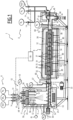
- Conversion installation 2 shown in the Figure 1 comprises a hydrolysis reactor 4 for the conversion of UF 6 into UO 2 F 2 powder, by reaction between gaseous UF 6 and dry water vapor injected into the reactor 4.
- the conversion plant 2 comprises a pyrohydrolysis furnace 6 for converting the UO 2 F 2 powder supplied by the reactor 4 into UO 2 powder, by reaction of the UO 2 F 2 powder with dry water vapor and gaseous H 2 injected into the furnace 6.
- the conversion plant 2 comprises a feed device 8 configured to inject the reactive gases (UF 6 gas, dry water vapor and H 2 gas) into the reactor 4 and into the furnace 6.
- the reactive gases UF 6 gas, dry water vapor and H 2 gas
- the feed device 8 is fed from sources of reactive gases, comprising at least one source of UF 6 gas, at least one source of dry water vapor and at least one source of H 2 gas.
- the feed device 8 comprises reactant injection conduits 10 for injecting the reactant gases into the reactor 4 and into the furnace 6.
- the reactant injection conduits 10 comprise a UF injection conduit 6 feeding the reactor 4, a first steam injection conduit feeding the reactor 4, a second steam injection conduit feeding the furnace 6 and an H2 injection conduit feeding the furnace 6.
- the feed device 8 is further configured for the injection of a neutral gas into the reactor 4, in particular in the production phase of the conversion plant 2, so that the conversion of UF 6 into UO 2 F 2 is carried out under a neutral gas atmosphere.
- the feed device 8 is configured to allow the injection of neutral gas into the reactor 4 without injecting neutral gas into the furnace 6.
- neutral sweep gas The neutral gas injected into reactor 4 during the production phase to carry out the conversion of UF 6 into UO 2 F 2 is subsequently called “neutral sweep gas”.
- the feed device 8 is preferably configured for the injection of the neutral sweep gas together with the dry water vapor (H 2 O) and the UF 6 .
- the supply device 8 comprises for example a concentric injector 11 allowing the water vapor to be injected.
- the feed device 8 is further configured for the injection of neutral gas into the reactor 4 and into the furnace 6, so as to be able to maintain a neutral gas atmosphere in the reactor 4 and in the furnace 6 when the conversion installation 2 is not in the production phase.
- the feed device 8 injects neutral sweep gas into the reactor 4 to carry out the conversion of UF 6 into UO 2 F 2 under a neutral gas atmosphere, without injecting neutral gas into the furnace 6, and, in the shutdown and start-up phase, the feed device 8 injects neutral gas into the reactor 4 and into the furnace 6 to maintain a neutral gas atmosphere.
- the feed device 8 comprises one or more neutral gas injection conduits 12 for injecting neutral gas into the reactor 4 and/or into the furnace 6.
- Each neutral gas injection conduit 12 is fed from a source of neutral gas.
- the neutral gas is preferably nitrogen (N 2 ).
- the concentric injector 11 is supplied by the reactant injection conduit 10 supplying the reactor 4 with steam (H 2 O), by the reactant injection conduit 10 supplying the reactor 4 with UF 6 , and by a neutral gas injection conduit 12, for injecting the neutral sweep gas into the reactor 4.
- the supply device 8 is configured to supply the reactant injection conduit 10 supplying the reactor 4 with steam (H 2 O) and/or the reactant injection conduit 10 supplying the reactor 4 with UF 6 with neutral gas during a shutdown or startup of the conversion plant 2.
- the feed device 8 comprises a respective feed actuator 14 arranged at the inlet of each reagent 10 or neutral gas 12 injection conduit, the feed actuator 14 making it possible to control the flow of gas in the injection conduit.
- the supply actuators 14 are provided in the form of flow regulators, capable of maintaining the gas flow passing through them at a set value.
- the supply actuators 14 of the supply device 8 are resistant to seismic stresses.
- the conversion installation 2 comprises an electronic control system 16 for controlling the conversion installation 2 and in particular the supply device 8, in particular the supply actuators 14.
- the reactor 4 delimits a reaction chamber 18 into which the reagent injection conduits 10 feed the reactor 4 with gaseous UF 6 and dry water vapor, and in which the conversion of the UF 6 into UO 2 F 2 by hydrolysis occurs.
- the UO 2 F 2 thus obtained is in the form of a powder falling to the bottom of the reaction chamber 18.
- the reactor 4 has an outlet pipe 20 extending from the reaction chamber 18 and connected to the furnace 6 for transferring the UO 2 F 2 powder from the bottom of the reaction chamber 18 to the furnace 6.
- the conversion installation 2 comprises a thermal enclosure 22 surrounding the reactor 4 and a heating device 24 for heating the internal volume of the thermal enclosure 22 and therefore the reactor 4.
- the furnace 6 has an inlet 26 connected to the outlet pipe 20 of the reactor 4 to receive the UO 2 F 2 powder and an outlet 28 to supply the UOz powder.
- the conversion plant 2 comprises a transfer device 30 for transferring the UO 2 F 2 powder from the reaction chamber 18 to the furnace 6.
- the transfer device 30 here comprises a motorized endless screw driven by a motor for pushing the UO 2 F 2 powder from the reaction chamber 18 to the inlet 26 of the furnace 6.
- the oven 6 comprises a drum 32 having a central axis C, one axial end of which forms the inlet 26 and the opposite axial end forms the outlet 28 of the oven 6.
- Drum 32 is provided for the circulation of UO 2 F 2 powder from inlet 26 to outlet 28 with circulation of dry water vapor and H 2 in furnace 6 countercurrent to the UO 2 F 2 powder.
- the drum 32 is rotatably mounted about its central axis C inclined relative to the horizontal so that the inlet 26 is higher than the outlet 28, the rotation of the drum 32 causing the powder to advance from the inlet 26 towards the outlet 28.
- the oven 6 comprises a motorized rotation drive device 33 configured to drive the drum 32 in rotation about its central axis C.
- the rotation drive device 33 comprises, for example, a motor and a transmission device, for example a chain or belt, coupling the motor to the drum 32.
- the oven 6 is advantageously equipped with a crank which allows the drum 32 to be rotated manually in the event of failure of the rotation drive device 33.
- the drum 32 is preferably provided with baffles 35 arranged inside the drum 32 to control the flow of reactive gases and the passage time of the powder in the oven 6.
- the drum 32 is provided with lifting members 37 arranged projecting from the internal surface of the drum 32 and configured to lift and drop the powder present in the drum 32 due to the rotation of the drum 32 about the central axis C, to improve the mixing of the powder and promote homogeneous contact of the powder particles with the reactive gases circulating in the drum 32.
- the lifting members 37 are for example in the form of lifting vanes or lifting angles distributed over the internal surface of the drum 32.
- the drum 32 of the furnace 6 and the transfer device 30 of the reaction chamber 18 are configured to operate independently of each other, in particular to allow the stopping of one while maintaining the operation of the other.
- the drum 32 of the furnace 6 and the transfer device 30 of the reaction chamber 18 are configured for independent rotation of the worm screw of the transfer device 30, on the one hand, and of the drum 32, on the other hand, and in particular for stopping the rotation of one of the worm screw and the drum 32 while maintaining the rotation of the other.
- This arrangement makes it possible, during the shutdown phases of the conversion installation 2, to finish removing the UO2 powder from the furnace 6 while the reactor 4, and in particular the transfer device 30, is already shut down.
- the second steam injection conduit and the H2 injection conduit feed the drum 32 via the outlet 28 for the circulation of the dry pyrohydrolysis steam and the H2 from the outlet 28 to the inlet 26 of the furnace 6.
- a neutral gas injection conduit 12 is connected to the reactant injection conduit 10 for injecting H2 into the furnace 6 and/or to the reactant injection conduit 10 for injecting H2O into the furnace 6, so as to inject neutral gas into the furnace 6 via this(these) reactant injection conduit(s) 10 when the conversion plant 2 is shut down or started up, the injected neutral gas then flowing from the outlet 28 of the furnace 6 to the inlet 26 of the furnace 6.
- the supply device 8 comprises a neutral gas injection conduit 12 for injecting neutral gas into the furnace 6 which opens directly into the furnace 6 without passing through a reactant injection conduit 10.
- the supply of a reagent injection pipe 10 with neutral gas when the conversion installation 2 is shut down makes it possible to purge this reagent injection pipe 10 when shutting down while injecting the neutral gas.
- the supply of a reagent injection pipe 10 with neutral gas during a start-up allows the temperature of the conversion installation 2 to rise and the supply of the conversion installation 2. conversion 2 into reactants when the reaction parameters are reached in reactor 4, respectively furnace 6.
- the oven 6 comprises a heating device 34 for heating the drum 32.
- the heating device 34 comprises heating elements 36 surrounding the drum 32 and distributed along the drum 32.
- the oven 6 comprises a thermal enclosure 38 surrounding the drum 32 and the heating elements 36.
- the conversion installation 2 comprises a collection device 40 for collecting the powder at the outlet of the furnace 6.
- the collection device 40 comprises an inlet pipe 42 connected to the outlet 28 of the furnace 6 and opening into a collection container 44.
- the collection device 40 comprises a thermal enclosure 46 surrounding the collection container 44.
- the second steam injection conduit and the H 2 injection conduit preferably open into the collection container 44.
- the conversion plant 2 comprises a capture device 50 for capturing and evacuating the gases rising into the reactor 4, comprising the excess reactive gases, hydrogen fluoride (HF) resulting from the conversion and the neutral gas.
- a capture device 50 for capturing and evacuating the gases rising into the reactor 4, comprising the excess reactive gases, hydrogen fluoride (HF) resulting from the conversion and the neutral gas.
- HF hydrogen fluoride
- the capture device 50 is arranged in the reactor 4, preferably in an upper region of the reaction chamber 18.
- the capture device 50 comprises a plurality of filters 52 for retaining solid materials which may be entrained by the gases rising in the reactor 4, in particular particles of UO 2 F 2 , or even UO 2 .
- the filters 52 are for example made of a porous material allowing the passage of excess reactive gases, neutral gas and HF resulting from the conversion reaction of UF 6 into UO 2 F 2 then into UO 2 while retaining a capacity for retaining UO 2 F 2 or UO 2 particles.
- the filters 52 are made of ceramic or nickel-based superalloy.
- UO 2 F 2 and UO 2 powders are volatile and easily carried away by gas streams. Furthermore, they tend to adhere to surfaces with which they come into contact.
- powder agglomerates are then created, more or less heterogeneous in terms of composition and more or less compact, on the filters 52 and on the walls of the reactor 4 and the furnace 6.
- These powder agglomerates containing fissile material can in particular concentrate in retention zones which may exist at various points in the conversion installation 2, such as for example at the junction between the reactor 4 and the furnace 6.
- Powder agglomerates may break off under their own weight and mix with UO 2 F 2 powder and UO 2 powder in the powdered state.
- the presence of clusters compacts in the powder creates powder processing heterogeneities in furnace 6 and can lead to the presence of residual UO 2 F 2 particles in the UO 2 powder obtained at the end of conversion, thus degrading its quality.
- the accumulation of powder on the filters 52 causes a progressive clogging of the filters 52 and results in an increase in the internal pressure of the reactor 4.
- the pressure variations have a significant impact on maintaining a constant quality of the UO 2 powder obtained at the end of conversion and an internal pressure that is too high in the reactor 4 can cause the conversion installation 2 to become safe.
- a blockage may also occur at the level of the device for injecting the reactants into the reactor 4, here the concentric injector 11. Indeed, if the pressure and the injection temperature of the gases are not sufficient, the UF 6 may crystallize at the outlet of the concentric injector 11 and thus block the supply of reactants to the reactor 4. It is therefore important to maintain a constant supply pressure, in particular when changing the UF 6 source.
- the conversion installation 2 advantageously comprises an unclogging device 53 configured for unclogging the filters 52, for example by pulsed injection of neutral gas through the filters 52 in counter-current, i.e. towards the inside of the reaction chamber 18 of the reactor 4.
- the neutral gas is for example nitrogen (N 2 ).
- the unclogging device 53 is configured to carry out the unclogging of the filters 52 in an automated manner, by carrying out the unclogging sequentially by groups of distinct filter(s) 52.
- the unclogging device 53 is then configured to inject the neutral gas counter-currently sequentially into the different groups of filters 52.
- Each group of filters 52 comprises a single filter 52 or several filters 52.
- the filters 52 are grouped into two groups each containing a respective half of the filters 52 and the unclogging is carried out alternately in the two groups with an injection of neutral gas carried out periodically, for example every 30 seconds. It is also possible to carry out the unclogging cycle, for example by third or by quarter and/or to adapt the injection frequency.
- the countercurrent neutral gas injection pressure in each filter 52 is chosen to limit disturbances in the reactor 4.
- a relative pressure applied to each filter 52 preferably between 2 and 5 bars, in particular between 3 and 4.5 bars, makes it possible to obtain satisfactory unclogging of the filter 52.
- relative pressure refers to the pressure difference relative to atmospheric pressure.
- the unclogging device 53 is for example supplied by a tank 55 containing the neutral gas and maintained at a constant pressure.
- the duration of injection of neutral gas in counter-current into each filter 52 is chosen to limit the disturbances in the reactor 4 while allowing satisfactory unclogging, in particular over the entire surface of the filter 52 during the injection duration.
- the duration of injection of neutral gas in counter-current into each filter 52 is for example less than 1 s.
- the capture device 50 when injecting counter-current neutral gas into each filter 52, is configured to cut off the suction through this filter 52 before the injection of counter-current neutral gas to prevent the neutral gas used for unclogging from escaping directly via the capture device 50.
- the unclogging device 53 is configured to perform the unclogging cyclically, in particular with a period chosen to avoid the accumulation of powders on the filters 52 while limiting the impact of this injection on the operation of the conversion installation 2.
- the period is between 30 seconds and 1 minute.
- the unclogging device is configured to repeat the unclogging sequence automatically in a cyclic (or periodic) manner.
- Automatic, sequential and periodic unclogging of the filters 52 makes it possible to ensure operation of the conversion installation 2, for example at a relative pressure of between 10 mbar and 500 mbar in the reactor 4, preferably between 50 and 400 mbar and more preferably between 100 and 350 mbar, which makes it possible to obtain a UO 2 powder having satisfactory characteristics, in particular a reasonable and substantially constant fluorine content over time.
- Unclogging the filters 52 causes the powder clumps formed on the filters 52 to fall and prevents an excessive pressure rise in the reaction chamber 18.
- Sequential and periodic unclogging makes it possible to limit the size and compactness of the agglomerates of solid materials formed on the filters 52 and to prevent them from detaching under their own weight and falling by gravity in too great a quantity to the bottom of the reaction chamber 18 in the transfer device 30.
- the mixing of compact agglomerates with the UO 2 F 2 powder in the pulverulent state can in fact induce heterogeneities in the physical and chemical characteristics of the UO 2 powder resulting therefrom and in particular in its fluorine content.
- the unclogging carried out by groups of several filters 52 prevents powder expelled from one filter 52 from sticking to another filter 52 as could be the case with individual unclogging of the filters 52.
- the unclogging carried out by groups of several filters 52 makes it possible to generate a powder mist and to limit the formation of clusters.
- the unclogging device 53 may comprise a manual or automatic control to enable one-off unclogging of the filters 52, in particular when they reach the end of their life and the sequential and periodic unclogging becomes insufficient.
- This one-off unclogging may be a unitary unclogging of the filters 52 or an unclogging of a group of filters 52 of reduced size.
- the conversion installation 2 further comprises at least one flow device 56 intended to prevent the accumulation of powder on the walls of the reaction chamber 18 and the sticking to the walls of the reaction chamber 18 of the powder clumps evacuated from the filters 52 during the unclogging operation.
- the flow device 56 makes it possible to promote a continuous flow of the powder and stable conditions for supplying the furnace 6 with UO 2 F 2 powder both in terms of quantity and quality, and in particular with a fluorine content that is stable over time.
- the flow device is configured to vibrate and/or impact at least one wall of the reactor 4, preferably regularly or continuously.
- the flow device 56 comprises for example one or more percussion members, each percussion member being configured to strike a wall of the reactor 4 so as to generate a shock wave in the walls of the reactor 4, and/or one or more vibrating members, for example vibrating pots, each vibrating member being arranged on a wall of the reactor 4 and configured to generate a vibratory signal (or vibration) and transmit this vibration to the walls of the reactor 4.
- the flow device 56 comprises one or more members which generate both shocks to detach the powder from the wall and vibrations to help it flow.
- the percussion organs, the vibrating organs and the organs delivering the two functions are called "flow organs".
- the flow device comprises at least one flow member configured to vibrate and/or strike a wall of the reactor 4.
- the flow organs allow the walls of the reactor 4 to vibrate regularly or even continuously.
- the flow device 56 here comprises four flow members 58, for example of the electro-percussive type, arranged two by two in two diametrically opposed positions on the outer surface of the wall of the reactor 4.
- the flow device 56 comprises several flow members 58
- the flow members 58 are controlled to act sequentially.
- the number, position and operating sequence of the flow members 58 can be adapted according to the geometry of the reactor 4, the quality of the powder and the operating parameters of the unclogging device 53.
- Each flow member 58 can be fixed directly to the wall of the reactor 4 or, for example, via an intermediate part.
- the intermediate part is for example removable to facilitate its maintenance.
- the combination of the unclogging device 53 and a flow device 56 makes it possible to limit the size and compactness of the powder clumps which are deposited on the filters 52 and on the walls of the reactor 4, to regulate the fall of the clumps at the bottom of the reactor 4 and thus to ensure the homogeneity of the UO 2 powder, in particular a fluorine content which is substantially constant over time.
- the conversion plant 2 comprises sealing devices 54 for ensuring sealing between the transfer device 30 and the reaction chamber 18, between the reactor 4 and the furnace 6 and between the furnace 6 and the collection device 40.
- the sealing devices 54 are arranged at the junction between the transfer device 30 and the reaction chamber 18, at the junction between the outlet pipe 20 of the reactor 4 and the inlet 26 of the furnace 6, and at the junction between the outlet 28 of the furnace 6 and the inlet pipe 42 of the collection device 40.
- the sealing devices 54 ensure sealing by allowing rotation of the transfer device 30 relative to the reactor 4 and rotation of the drum 32 of the furnace 6 relative to the reactor 4 and the collection device 40.
- the sealing devices 54 are pressurized with a neutral gas, and preferably nitrogen.
- the conversion installation 2 comprises for example pressurization supplies 57 arranged to supply the sealing devices 54 with a neutral pressurization gas.
- the pressure of the neutral gas supplying the sealing devices 54 is higher than that present in the conversion installation 2 to avoid any dissemination of powder outside the conversion installation 2.
- the neutral gas pressurizing the sealing devices 54 is likely to pass into the reactor 4 and/or into the furnace 6, and the operating parameters of the reactor 4 and the furnace 6 are adapted to take into account this supply of neutral gas.
- the conversion installation 2 comprises at least one percussion device 60 for striking a percussion surface 62 of the furnace 6 so as to detach the UO 2 F 2 or UO 2 powder from the internal surface of the drum 32.
- the conversion installation 2 here comprises a percussion device 60 arranged at each axial end of the drum 32 to strike a percussion surface 62 formed by the external surface of the axial end of the drum 32 axially exiting the thermal enclosure 38 of the furnace 6.
- the percussion surface 62 is defined by any other surface of the furnace 6 making it possible to transmit vibrations to the peripheral wall of the drum 32 when this percussion surface 62 of the furnace 6 is struck.
- the conversion installation 2 can advantageously comprise several percussion devices 60 arranged at the same end of the drum 32 while being distributed angularly around the drum 32.
- the conversion installation 2 comprises two groups of percussion devices 60, each group being arranged at a respective end among the two ends of the drum 32, and the percussion devices 60 of each group being angularly distributed around the drum 32.
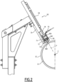
- the percussion devices 60 are similar. Only one percussion device 60 is illustrated in more detail in the Figure 2 .
- each percussion device 60 comprises a striker 64 movable relative to the percussion surface 62 in a percussion direction P and an intermediate piece 66 arranged between the striker 64 and the percussion surface 62 so that the striker 64 strikes the percussion surface 62 via the intermediate piece 66, the intermediate piece 66 being movable in the percussion direction P between a position spaced from the percussion surface 62 and a position of contact with the percussion surface 62 of the furnace 6.
- the percussion direction P is here perpendicular to the plane tangent to the percussion surface 62 at the point of contact of the intermediate part 66 with the percussion surface 62.
- the percussion direction P is here substantially radial relative to the central axis C of the drum 32.
- the striker 64 is carried by a percussion actuator 68 capable of moving the striker 64 in alternating translation in the percussion direction P.
- the percussion actuator 68 is here a double-acting hydraulic or pneumatic cylinder.
- the percussion device 60 has a support 70 carrying the actuator 68 and the intermediate piece 66, so that the intermediate piece 66 is located between the striker 64 and the percussion surface 62.
- the intermediate piece 66 is slidably mounted on the support 70 in the percussion direction P.
- the intermediate piece 66 has a rear surface 66A intended to be struck by the striker 64, and a front surface 66B intended to come into contact with the percussion surface 62. In the contact position, the front surface 66B is in contact with the percussion surface 62, and in the spaced position, the front surface 66B is spaced from the percussion surface 62.
- the percussion device 60 comprises an elastic return member 72 arranged to return the intermediate piece 66 to a spaced position.
- the intermediate piece 66 is received in a housing 74 of the support 70, the elastic member 72 being interposed between an internal shoulder 74A of the housing 74 and an external shoulder 66C of the intermediate piece 66.
- the elastic member 72 is here a helical spring surrounding the intermediate piece 66 and compressed when the intermediate piece 66 moves from the spaced position to the contact position.
- the percussion device 60 comprises a position sensor 76 making it possible to know the position of the striker 64.
- the position sensor 76 is for example an inductive sensor arranged near the intermediate part 66, and making it possible to determine whether or not the striker 64 is in contact with the intermediate part 66.
- the percussion actuator 68 is controlled as a function of the position signal provided by the position sensor 76.
- the percussion actuator 68 moves the striker 64 in reciprocating translation so as to move the striker 64 away from the intermediate piece 66 and then move the striker 64 against the intermediate piece 66, so as to strike the percussion surface 62 via the intermediate piece 66.
- the striker 64 moves the intermediate piece 66 from the spaced position to the contact position against the elastic member 72.
- an intermediate part 66 distinct from the striker 64 and which is not permanently connected to the furnace 6, makes it possible to use the intermediate part 66 as a sacrificial part or wear part.
- the intermediate part 66 is mounted movably relative to the furnace 6.
- an impurity content essentially fluorine
- the supply device 8 is configured to supply the reactants and the neutral gas, in particular the neutral sweep gas, with determined flow rates.
- the heating device 24 of the reactor 4 is configured to maintain the chamber of the reactor 4 in a temperature range suitable for obtaining UO 2 F 2 and then UO 2 powders with the desired characteristics.
- the hourly mass flow rate of feeding the reactor 4 with gaseous UF 6 is between 75 and 130 kg/h
- the hourly mass flow rate of feeding the reactor 4 with dry hydrolysis steam is between 15 and 30 kg/h
- the temperature in the reactor 4 is between 150 and 250°C.
- the hourly mass flow rate of feeding the reactor 4 with gaseous UF 6 is between 90 and 120 kg/h and the hourly mass flow rate of feeding the reactor 4 with dry hydrolysis water vapor is between 20 and 25 kg/h.
- reactor 4 is supplied with UF 6 at a supply temperature between 75°C and 130°C, preferably between 90°C and 120°C.
- the conversion installation 2 comprises an emission device making it possible to emit the UF 6 continuously towards the reactor 4 with a regulated UF 6 flow rate and temperature.
- UF 6 is transported in tanks that are, for example, cylindrical. At room temperature, UF 6 is in the solid state. The transition from the solid state to the gaseous state is carried out by heating the tanks, for example in a heating chamber, in particular in an oven (not sealed) or in an autoclave (sealed).
- the conversion plant 2 has an emission device 82 for supplying the reactor 4 with gaseous UF 6 from tanks 84 containing UF 6 .
- Each tank 84 is closed by a sealing valve 85.
- the emission device 82 comprises at least two heating enclosures 86, each heating enclosure 86 being provided to receive a reservoir 84 of UF 6 in the solid state and heat it to generate UF 6 in the gaseous state, the emission device 82 being configured to supply the reactor 4 sequentially from the heating enclosures 86, passing from a current heating enclosure 86 to a following heating enclosure 86 when the reservoir 84 received in said current heating enclosure 86 is no longer sufficiently full, preferably without interruption of the flow of gaseous UF 6 supplying the reactor 4.
- each heating enclosure 86 is capable of heating and maintaining the respective reservoir 84 at a temperature higher than the triple point temperature of UF 6 , for example at a temperature higher than 75°C and preferably at a nominal temperature of 95°C, for example 95°C ⁇ 10°C.
- the emission device 82 thus comprises a supply circuit 87 configured for the emission of UF 6 to the reactor 4 selectively from one of the heating enclosures 86, while each other heating enclosure 86 heats a reservoir 84 awaiting the emission of UF 6 from this reservoir 84 or is recharged with a reservoir 84 filled with UF 6 .
- Each heating enclosure 86 is for example connected to the reactor 4 via a respective flow control valve 88, the closing of which makes it possible to isolate the heating enclosure 86 from the reactor 4 and the opening of which makes it possible to fluidically connect the heating enclosure 86 to the reactor 4.
- the opening of the valve 85 of the reservoir 84 then of the valve 88 allows the flow of UF 6 from the heating enclosure 86 to the reactor 4 due to a pressure difference between the reservoir 84 and the reactor 4.
- the heating enclosure 86 is then in a passive emission mode.
- each tank 84 is connected to the reactor 4 via a respective pump 90 associated with each heating enclosure 86 and arranged in parallel with the valve 88 associated with this heating enclosure 86.
- the pump 90 is preferably a positive displacement pump and more preferably a volumetric bellows pump.
- Activation of the pump 90 makes it possible to force the circulation of the gaseous UF 6 from the heating enclosure 86 to the reactor 4 when the pressure in the tank 84 contained in the heating enclosure 86 is insufficient to ensure this circulation.
- the heating enclosure 86 is then in an active emission mode.
- the valve 88 When the valve 88 is open, the pump 90 is bypassed.
- the emission device 82 comprises for example a device for opening the valve of the respective tank 84 from outside each heating enclosure 86 and an electronic control unit 92 configured to control the valve 88 and, where appropriate, the pump 90 associated with each heating enclosure 86 and to ensure the supply sequentially from the heating enclosures 86, and, where appropriate, the transition from passive mode to active mode for each heating enclosure 86.
- the emission device 82 is for example configured to control the passage from one heating enclosure 86 to the next, and where appropriate the passage from passive mode to active mode in a manner controlled by the pressure in each tank 84.
- the emission device 82 comprises for example a pressure sensor 94 associated with each tank 84, the electronic control unit 92 being configured to control the valve 88 and where appropriate the pump 90 associated with each heating enclosure 86 as a function of the measurements provided by the pressure sensors 94.
- a tank 84 is heated in a first heating enclosure 86 preferably under a neutral gas atmosphere to improve the heat exchanges between the atmosphere of the heating enclosure 86 and the tank 84.
- the neutral gas is for example nitrogen.
- the pressure in the reservoir 84 of the first heating enclosure 86 drops to a value close to that which can cause a drop in the flow rate of UF 6 and the inversion of flows between the reactor 4 and the reservoir 84 received in this first heating enclosure 86. There then still remain several kilograms of UF 6 in the reservoir 84.
- the first heating enclosure 86 switches from passive emission mode to active emission mode with the closing of the valve 88 and the starting of the corresponding pump 90. The emission of UF 6 can thus continue until emission of almost all of the UF 6 contained in the reservoir 84 of the first heating enclosure 86, with for example a pressure at the end of emission of 100 mbar absolute in the reservoir 84.
- the reservoir 84 received in the second heating enclosure 86 has reached the temperature required for the emission of UF 6 and the sealing valve 85 of the reservoir 84 is open.
- the valve 88 associated with the first heating enclosure 86 closes and the valve 88 associated with the second heating enclosure 86 opens and the emission of UF 6 continues from the reservoir 84 of the second heating enclosure 86 without interruption and without significant modification of the flow rate, temperature and pressure of the UF 6 during the switch from the first heating enclosure 86 to the second heating enclosure 86.
- the valve 85 of the reservoir 84 received in the first heating enclosure 86 is closed and, after cooling, the first heating enclosure 86 is vented to the atmosphere, unlocked and the reservoir 84 is evacuated and replaced by a new reservoir 84 filled with UF 6 .
- the valve 88 associated with the second heating enclosure 86 can open before the valve 88 associated with the first heating enclosure 86 closes and the emission of UF 6 continues from the two tanks 84, the first heating enclosure 86 operating in active emission mode and the second heating enclosure 86 operating in passive emission mode.
- the opening of the valve 88 associated with the second heating enclosure 86 can occur for example at the time of closing the valve 88 and starting the pump 90 of the first heating enclosure 86 or at any other time before stopping the emission of UF 6 by the tank 84 of the first heating enclosure 86.
- valves 88 are resistant to seismic stresses.
- the emission device 82 allows continuous production of the conversion plant 2, using almost all of the UF 6 contained in the tanks 84 with an emission of UF 6 at the required pressure and temperature and with the required flow rate.
- the reactor 4 is supplied with dry hydrolysis steam at a supply temperature of between 175°C and 300°C, in particular between 200°C and 270°C.
- the furnace 6 is supplied with dry pyrohydrolysis steam with an hourly mass feed flow rate of between 25 and 40 kg/h, in particular between 30 and 35 kg/h.
- the furnace 6 is supplied with dry pyrohydrolysis steam at a supply temperature of between 250°C and 450°C, preferably between 300°C and 400°C.
- the volume flow rate of the H 2 feed to the furnace 6 is between 10 and 25 Nm 3 /h, in particular between 15 and 20 Nm 3 /h (“Nm 3 /h” means normal cubic meters per hour and is a unit of measurement of the quantity of gas which corresponds to the content of a volume of one cubic meter, for a gas under normal temperature and pressure conditions (20°C and 1 atm)).
- the H 2 is generally injected at room temperature.
- the injection parameters of the neutral sweep gas feeding reactor 4 influence the reactions occurring in reactor 4.
- the feed rate of the neutral sweep gas of the reactor 4 is between 1.5 and 5 Nm 3 /h
- the injection temperature of the neutral sweep gas is between 80°C and 130°C
- the relative feed pressure of this neutral sweep gas is higher than the relative pressure inside the reactor 4 and is preferably less than 1 bar.
- the feed rate of the neutral sweeping gas is between 2 and 3 Nm 3 /h and the injection temperature of the neutral sweeping gas is between 90 and 105°C.
- the heating elements 36 of the oven 6 are controlled to establish in the oven 6 a temperature which gradually increases then decreases from the inlet 26 of the oven 6 towards the outlet 28 of the oven 6.
- the oven 6 comprises for example several successive sections defined along the oven 6, here six successive sections S1 to S6 from the inlet 26 to the outlet 28 of the oven 6, each section S1 to S6 being heated by heating elements 36 dedicated to this section S1 to S6.
- the oven 6 comprises a respective temperature sensor 80 associated with each section S1 to S6.
- the temperature of each section of the oven 6 is considered to be that measured by the temperature sensor 80 associated with this section.
- Each temperature sensor 80 is for example a thermocouple adjacent to the heating elements 36 associated with the section.
- the heating elements 36 dedicated to each section S1 to S6 are controlled independently of those dedicated to the other sections so that the temperature measured by the temperature sensor 80 located in this section is at a determined set value.
- each section S1 to S6 is provided with several temperature sensors 80 and the temperature of each section S1 to S6 of the oven 6 is considered to be the average of the temperatures measured by the temperature sensors 80 in operation associated with this section S1 to S6.
- the unclogging device 53 performs periodic unclogging, automatically and regularly.
- the flow device 56 vibrates and/or impacts the reactor 4, automatically, regularly or continuously, and/or the percussion device 60 impacts the furnace 6, automatically and regularly, to cause the powder stuck to the internal walls to fall off before it forms large and/or compact clumps.
- the filters 52 may nevertheless become excessively clogged as the conversion installation 2 operates and they age.
- the increase in relative pressure inside reactor 4 is generally representative of the fact that the cleaning of filters 52 is becoming insufficient.
- the relative pressure inside the reactor 4 remains between 10 mbar and 500 mbar, preferably between 50 and 400 mbar and more preferably between 100 and 350 mbar.
- Conversion plant 2 includes a pressure sensor P1 to measure the pressure inside reactor 4.
- control system 16 is configured to command a shutdown of the conversion installation 2.
- the safety threshold is, for example, between 100 and 500 mbar, preferably between 200 and 450 mbar and even more preferably between 200 and 400 mbar, in particular around 350 mbar.
- the unclogging device 53 is controlled to perform one-time unclogging of the filters 52.
- the one-time unclogging can be performed with an unclogging injection pressure in the upper part of the sequential unclogging neutral gas injection pressure range or even at an injection pressure higher than said range.
- the one-time unclogging can also be performed specifically on one or more filters 52, for example individually on one or more particular filters 52 that are clogged, or together on a limited number of filters 52.
- the one-off cleaning threshold is, for example, set in a range of 100 mbar below the safety pressure of the installation and is, for example, 50 mbar and preferably 30 mbar below the safety threshold of the installation.
- each filter 52 During unclogging, the injection of neutral gas inside each filter 52 makes it possible to expel the UO 2 F 2 powder particles trapped on the external surface of the filter 52, while limiting the disturbances of the reactor 4 operating at a relative pressure between 10 mbar and 500 mbar.
- the vibration and/or impact of one or more walls of the reactor 4, here by the flow device 56 equipping the reactor 4, also makes it possible to detach the UO 2 F 2 powder particles which may be deposited on the internal wall of the reactor 4.
- Control of the flow rates of reactive gases and neutral sweep gas and of the temperature in reactor 4 and in furnace 6 also allows the establishment of hydrolysis and pyrohydrolysis reactions under conditions for obtaining satisfactory UO 2 powder.
- all of the gases injected into the reactor 4 or into the furnace 6 are injected at a pressure higher than that existing in the reactor 4 or the furnace 6, for example at a pressure at least 20 mbar above the pressure inside the reactor 4 or the furnace 6, and preferably at least 50 mbar above.
Landscapes
- Engineering & Computer Science (AREA)
- Chemical & Material Sciences (AREA)
- Physics & Mathematics (AREA)
- Organic Chemistry (AREA)
- High Energy & Nuclear Physics (AREA)
- General Engineering & Computer Science (AREA)
- Plasma & Fusion (AREA)
- Chemical Kinetics & Catalysis (AREA)
- Life Sciences & Earth Sciences (AREA)
- General Life Sciences & Earth Sciences (AREA)
- Geology (AREA)
- Inorganic Chemistry (AREA)
- Ceramic Engineering (AREA)
- Manufacturing & Machinery (AREA)
- Devices And Processes Conducted In The Presence Of Fluids And Solid Particles (AREA)
- Physical Or Chemical Processes And Apparatus (AREA)
- Inorganic Compounds Of Heavy Metals (AREA)
Claims (17)
- Umwandlungsverfahren von Uranhexafluorid UF6, in Uraniumdioxid, UO2, das Verfahren umfassend die folgenden Schritte:- Hydrolyse von UF6 zu Uranoxyfluorid UO2F2, in einem Hydrolysereaktor (4) durch Reaktion zwischen gasförmigem UF6 und trockenem Wasserdampf, der in den Reaktor (4) eingespritzt wird, und- Pyrohydrolyse von UO2F2 zu UO2 in einem Pyrohydrolyseofen (6) durch Reaktion von UO2F2 mit trockenem Wasserdampf und Wasserstoffgas, H2, das in den Ofen (6) eingespritzt wird,wobei der stündliche Massendurchsatz zu Beschicken des Reaktors (4) mit gasförmigem UF6 zwischen 75 und 130 kg/h liegt, der stündliche Massendurchsatz zum Beschicken des Reaktors (4) mit trockenem Hydrolysedampf zwischen 15 und 30 kg/h liegt und die Temperatur in dem Reaktor (4) zwischen 150 und 250 °C liegt.
- Umwandlungsverfahren nach Anspruch 1, umfassend das Einspritzen eines neutralen Spülgases in den Reaktor (4).
- Umwandlungsverfahren nach Anspruch 1 oder 2, wobei das UO2 in Form eines UO2-Pulvers erlangt wird, das eine spezifische Kornoberfläche zwischen 1 m2/g und 4 m2/g, vorzugsweise zwischen 1,9 m2/g und 2,9 m2/g aufweist.
- Umwandlungsverfahren nach einem der vorherigen Ansprüche, wobei das UO2 einen Restgehalt an Fluor, F, von weniger als 50 ppm, vorzugsweise weniger als 35 ppm, aufweist.
- Umwandlungsverfahren nach einem der vorherigen Ansprüche, wobei das UF6, mit dem der Reaktor (4) beschickt wird, auf einer Temperatur zwischen 75 °C und 130 °C, vorzugsweise zwischen 90 °C und 100 °C, ist.
- Umwandlungsverfahren nach einem der vorherigen Ansprüche, wobei der trockene Hydrolysedampf, mit dem der Reaktor (4) beschickt wird, auf einer Temperatur zwischen 175 und 300 °C, vorzugsweise zwischen 200 und 270 °C, ist.
- Umwandlungsverfahren nach einem der vorherigen Ansprüche, wobei der stündliche Massenstrom von trockenem Pyrohydrolysedampf, der dem Ofen (6) zugeführt wird, zwischen 25 und 40 kg/h, vorzugsweise zwischen 30 und 35 kg/h, liegt.
- Umwandlungsverfahren nach einem der vorherigen Ansprüche, wobei die Temperatur des trockenen Pyrohydrolysedampfs, der dem Ofen (6) zugeführt wird, zwischen 250 und 450 °C, vorzugsweise zwischen 300 und 400 °C, liegt.
- Umwandlungsverfahren nach einem der vorherigen Ansprüche, wobei der Volumenstrom zum Beschicken des Ofens (6) mit H2 zwischen 10 und 25 Nm3/h, insbesondere zwischen 15 und 20 Nm3/h, liegt.
- Umwandlungsverfahren nach einem der vorherigen Ansprüche, wobei die Beschickungsrate des Reaktors (4) mit neutralen Spülgas zwischen 1,5 und 5 Nm3/h liegt, die Temperatur des neutralen Spülgases, mit dem der Reaktor (4) beschickt wird, zwischen 80 °C und 130 °C liegt und der relative Beschickungsdruck des neutralen Spülgases höher ist als der relative Druck im Inneren des Reaktors (4) und vorzugsweise unter 1 bar ist.
- Umwandlungsverfahren nach einem der vorherigen Ansprüche, umfassend das Beschicken des Reaktors (4) mit gasförmigem UF6 aus einer Emissionsvorrichtung (82), umfassend mindestens eine Heizkammer (86), wobei die oder jede Heizkammer (86) einen Behälter (84) mit UF6 in festem Zustand aufnimmt und diesen erhitzt, um UF6 in gasförmigem Zustand zu erzeugen, und einen Beschickungskreislauf (87), der konfiguriert ist, um den Reaktor (4) aus der oder jeder Heizkammer (86) zu beschicken.
- Umwandlungsverfahren nach Anspruch 11, wobei die Emissionsvorrichtung (82) mindestens zwei Heizkammern (86) umfasst, wobei der Beschickungskreislauf (87) konfiguriert ist, um den Reaktor (4) sequentiell aus den Heizkammern (86) zu beschicken, indem er von einer aktuellen Heizkammer (86) zu einer nächsten Heizkammer (86) wechselt, wenn der in der aktuellen Heizkammer (86) aufgenommene Behälter (84) nicht mehr ausreichend gefüllt ist.
- Umwandlungsverfahren nach Anspruch 12, wobei die Beschickung des Reaktors (4) aus dem nächsten Heizbehälter (86) beginnt, bevor die Beschickung des Reaktors (4) aus dem aktuellen Heizbehälter (86) angehalten wird, sodass die Beschickung des Reaktors (4) aus beiden Heizbehältern (86) über eine Zeitdauer gleichzeitig erfolgt.
- Umwandlungsverfahren nach einem der Ansprüche 11 bis 13, wobei der Beschickungskreislauf (87) eine Pumpe (90) umfasst, die mit der oder jeder Heizkammer (86) assoziiert ist, um die Zirkulation des UF6 aus dem in der Heizkammer (86) aufgenommenen Reservoir (84) zu dem Reaktor (4) zu erzwingen, wobei die oder jede Pumpe (90) vorzugsweise eine Verdrängerpumpe und noch bevorzugter eine volumetrische Balgpumpe ist.
- Umwandlungsverfahren nach Anspruch 14, wobei der Beschickungskreislauf (87) ein Ventil (88) zur Durchflussregelung umfasst, das mit dem oder jedem Heizgefäß (86) assoziiert ist und in dem Bypass zu der mit dem Heizgefäß (86) assoziierten Pumpe (90) angeordnet ist.
- Umwandlungsanlage von Uranhexafluorid, UF6, in Urandioxid, UO2, die Umwandlungsanlage umfassend:- einen Reaktor (4) zur Hydrolyse von UF6 zu Uranoxidfluoridpulver, UO2F2, durch Reaktion zwischen gasförmigem UF6 und trockenem Wasserdampf, der in den Reaktor (4) eingespritzt wird,- einen Ofen (6) zur Pyrohydrolyse des UO2F2-Pulvers zu UO2-Pulver durch Reaktion des UO2F2-Pulvers mit trockenem Wasserdampf und Wasserstoffgas, H2, das in den Ofen (6) eingespritzt wird, und- eine Beschickungsvorrichtung (8) des Reaktors (4) und des Ofens (6) mit reaktiven Gasen und neutralem Spülgas,dadurch gekennzeichnet, dass die Umwandlungsanlage für die Durchführung eines Verfahrens nach einem der vorherigen Ansprüche konfiguriert ist.
- Umwandlungsanlage nach Anspruch 16, umfassend eine Emissionsvorrichtung (82) zum Beschicken des Reaktors (4) mit UF6, die Emissionsvorrichtung (82) umfassend mindestens eine Heizkammer (86), wobei die oder jede Heizkammer (86) konfiguriert ist, um einen Reservoir (84) mit UF6 in festem Zustand aufzunehmen und diesen zu erhitzen, um UF6 in gasförmigem Zustand zu erzeugen, und einen Beschickungskreislauf (87), der konfiguriert ist, um den Reaktor (4) aus der oder jeder Heizkammer (86) zu beschicken.
Applications Claiming Priority (1)
| Application Number | Priority Date | Filing Date | Title |
|---|---|---|---|
| PCT/FR2018/052497 WO2020074792A1 (fr) | 2018-10-09 | 2018-10-09 | Procédé et installation de conversion d'hexafluorure d'uranium en dioxyde d'uranium |
Publications (2)
| Publication Number | Publication Date |
|---|---|
| EP3864675A1 EP3864675A1 (de) | 2021-08-18 |
| EP3864675B1 true EP3864675B1 (de) | 2024-08-28 |
Family
ID=65411892
Family Applications (1)
| Application Number | Title | Priority Date | Filing Date |
|---|---|---|---|
| EP18847189.0A Active EP3864675B1 (de) | 2018-10-09 | 2018-10-09 | Verfahren und anlage zur umwandlung von uranhexafluorid in urandioxid |
Country Status (9)
| Country | Link |
|---|---|
| US (1) | US12087458B2 (de) |
| EP (1) | EP3864675B1 (de) |
| JP (1) | JP7142156B2 (de) |
| KR (1) | KR102573251B1 (de) |
| CN (1) | CN112840410B (de) |
| EA (1) | EA202190742A1 (de) |
| ES (1) | ES2992890T3 (de) |
| WO (1) | WO2020074792A1 (de) |
| ZA (1) | ZA202102099B (de) |
Families Citing this family (3)
| Publication number | Priority date | Publication date | Assignee | Title |
|---|---|---|---|---|
| PL3864673T3 (pl) * | 2018-10-09 | 2024-07-15 | Framatome | Sposób oraz instalacja do konwersji sześciofluorku uranu w dwutlenek uranu |
| CN114637343B (zh) * | 2022-03-23 | 2024-08-27 | 中国核电工程有限公司 | 一种六氟化铀转化物料流量控制系统及方法 |
| CN119804211B (zh) * | 2025-01-03 | 2026-01-16 | 中国原子能科学研究院 | 二氧化铀的氟化速率的测量装置及测量方法 |
Family Cites Families (29)
| Publication number | Priority date | Publication date | Assignee | Title |
|---|---|---|---|---|
| US3260575A (en) * | 1964-11-19 | 1966-07-12 | Richard L Heestand | Single-step process for preparation of uranium dioxide from uranium hexafluoride |
| US3734694A (en) * | 1968-04-25 | 1973-05-22 | Gen Electric | Apparatus for producing uo2 powder |
| US3579311A (en) * | 1968-04-25 | 1971-05-18 | Gen Electric | Process and apparatus for producing uo2 powder |
| US4020146A (en) * | 1969-07-18 | 1977-04-26 | Westinghouse Electric Corporation | Production of uranium dioxide |
| US3845193A (en) | 1969-10-15 | 1974-10-29 | Atomic Energy Authority Uk | Production of uranium dioxide in a rotary kiln |
| BE757513A (fr) | 1969-10-15 | 1971-04-14 | Atomic Energy Authority Uk | Production d'oxydes d'uranium |
| US3698697A (en) | 1970-04-23 | 1972-10-17 | Atomic Energy Authority Uk | Rotary kilns |
| US3937784A (en) * | 1971-06-01 | 1976-02-10 | Rbg, Reaktorbrennelemente Gmbh | Method for removing fluoride ions from UO2 powders |
| US3906081A (en) * | 1973-05-31 | 1975-09-16 | Exxon Nuclear Co Inc | Fluidized reactor reduction of UF{HD 6 {B to UO{HD 2 |
| FR2310315A1 (fr) * | 1975-05-09 | 1976-12-03 | Commissariat Energie Atomique | Procede et dispositif de fabrication d'oxyde d'uranium uo2 par voie seche |
| US4053559A (en) * | 1976-06-14 | 1977-10-11 | Westinghouse Electric Corporation | Production of uranium dioxide |
| US4120936A (en) * | 1977-02-28 | 1978-10-17 | Exxon Research & Engineering Co. | Process for conversion of UF6 to UO2 |
| JPS61281019A (ja) | 1985-06-04 | 1986-12-11 | Mitsubishi Metal Corp | 六フツ化ウランを二酸化ウランに変換する方法 |
| FR2771725B1 (fr) * | 1997-11-28 | 2000-02-04 | Franco Belge Combustibles | Procede et dispositif de conversion directe d'hexafluorure d'uranium en oxyde d'uranium |
| FR2771655B1 (fr) * | 1997-11-28 | 2000-01-28 | Franco Belge Combustibles | Procede et dispositif de preparation d'un compose solide pulverulent par reaction entre deux reactifs gazeux |
| FR2788760B1 (fr) | 1999-01-27 | 2001-03-23 | Cogema | Systeme de transfert de chaleur pour reacteur de conversion d'uf6 en oxyde d'uranium |
| FR2805044B1 (fr) | 2000-02-11 | 2002-05-17 | Franco Belge Combustibles | Procede et dispositif de determination de l'evolution d'une reaction chimique dans un four et de reglage de la reaction |
| FR2818159B1 (fr) | 2000-12-15 | 2003-10-03 | Franco Belge Combustibles | Procede et dispositif de decolmatage d'un filtre d'une installation de production d'oxyde d'uranium a partir d'hexafluorure d'uranium |
| RU2240286C2 (ru) | 2001-06-04 | 2004-11-20 | Открытое акционерное общество "Ульбинский металлургический завод" | Способ получения порошка диоксида урана для керамического ядерного топлива |
| RU2211185C2 (ru) | 2001-06-21 | 2003-08-27 | Открытое акционерное общество "Машиностроительный завод" | Способ для конверсии гексафторида урана в оксиды урана и устройство для его осуществления |
| US7824640B1 (en) | 2006-07-25 | 2010-11-02 | Westinghouse Electric Co. Llc | Two step dry UO2 production process utilizing a positive sealing valve means between steps |
| EP1985587A1 (de) | 2007-04-27 | 2008-10-29 | Westinghouse Electric Company LLC | Zweistufiges Verfahren zur Herstellung von trockenem UO2 |
| CN101830505A (zh) * | 2010-04-20 | 2010-09-15 | 江西泛美亚材料有限公司 | 一种氧化钪稳定氧化锆粉体及其制备方法 |
| FR3015462B1 (fr) | 2013-12-20 | 2015-12-18 | Commissariat Energie Atomique | Procede et installation pour la production conjointe de composes de l'uranium et d'acide fluorhydrique anhydre. |
| FR3037331B1 (fr) | 2015-06-12 | 2019-09-13 | Orano Cycle | Installation, procede de denitration thermique, utilisation d'une telle installation et produit obtenu par un tel procede |
| WO2017119306A1 (ja) | 2016-01-04 | 2017-07-13 | 株式会社日立産機システム | 配管ネットワーク評価装置および方法 |
| KR101856467B1 (ko) | 2017-06-01 | 2018-05-11 | 한전원자력연료 주식회사 | 기상반응을 통한 6불화우라늄 실린더 내부 잔여물 처리방법 및 처리장치 |
| EA202190743A1 (ru) * | 2018-10-09 | 2021-07-26 | Фраматом | Устройство и способ для превращения гексафторида урана в диоксид урана |
| PL3864673T3 (pl) * | 2018-10-09 | 2024-07-15 | Framatome | Sposób oraz instalacja do konwersji sześciofluorku uranu w dwutlenek uranu |
-
2018
- 2018-10-09 ES ES18847189T patent/ES2992890T3/es active Active
- 2018-10-09 EA EA202190742A patent/EA202190742A1/ru unknown
- 2018-10-09 WO PCT/FR2018/052497 patent/WO2020074792A1/fr not_active Ceased
- 2018-10-09 JP JP2021520108A patent/JP7142156B2/ja active Active
- 2018-10-09 CN CN201880098561.6A patent/CN112840410B/zh active Active
- 2018-10-09 US US17/282,916 patent/US12087458B2/en active Active
- 2018-10-09 EP EP18847189.0A patent/EP3864675B1/de active Active
- 2018-10-09 KR KR1020217010318A patent/KR102573251B1/ko active Active
-
2021
- 2021-03-29 ZA ZA2021/02099A patent/ZA202102099B/en unknown
Also Published As
| Publication number | Publication date |
|---|---|
| CN112840410A (zh) | 2021-05-25 |
| EA202190742A1 (ru) | 2021-08-13 |
| KR102573251B1 (ko) | 2023-08-30 |
| ZA202102099B (en) | 2022-07-27 |
| WO2020074792A1 (fr) | 2020-04-16 |
| JP7142156B2 (ja) | 2022-09-26 |
| EP3864675A1 (de) | 2021-08-18 |
| CN112840410B (zh) | 2024-08-16 |
| US20210398699A1 (en) | 2021-12-23 |
| BR112021005799A2 (pt) | 2021-06-29 |
| US12087458B2 (en) | 2024-09-10 |
| ES2992890T3 (en) | 2024-12-19 |
| JP2022519141A (ja) | 2022-03-22 |
| KR20210048555A (ko) | 2021-05-03 |
Similar Documents
| Publication | Publication Date | Title |
|---|---|---|
| EP3864673B1 (de) | Verfahren und vorrichtung zur uberführung von uranhexafluorid in urandioxyd | |
| EP0960070B1 (de) | Verfahren und vorrichtung zur direkten umsetzung von uranhexafluorid in uranoxid | |
| EP3864675A1 (de) | Verfahren und anlage zur umwandlung von uranhexafluorid in urandioxid | |
| WO2004069742A1 (fr) | Procede et installation pour la fabrication de nanotubes de carbone | |
| EP1572326A1 (de) | Verfahren und vorrichtung zur behandlung von abgasen aus elektrolysezellen für die herstellung von aluminium | |
| EP0711254A1 (de) | Verfahren zum inertiren von metallhaltigen produkten mittels eines plasmabrenners insbesondere schwermetalle und vorrichtung zum ausführen dies verfahrens | |
| FR2463893A1 (fr) | Procede et appareil d'incineration auto-entretenue d'agglomeres combustibles facilement friables a forte teneur en eau | |
| EA043959B1 (ru) | Способ и установка конверсии гексафторида урана в диоксид урана | |
| EA045072B1 (ru) | Способ и оборудование для превращения гексафторида урана в диоксид урана | |
| EP3864674A1 (de) | Anlage und verfahren zur umwandlung von uranhexafluorid in urandioxid | |
| BR112021006260B1 (pt) | Método de conversão de hexafluoreto de urânio (uf6) em dióxido de urânio (uo2) e instalação de conversão | |
| BR112021005799B1 (pt) | Método de conversão de hexafluoreto de urânio em dióxido de urânio e instalação de conversão de hexafluoreto de urânio em dióxido de urânio | |
| FR2803283A1 (fr) | Procede et dispositif pour la transformation en continu de l'oxalate de plutonium en oxyde de plutonium | |
| WO1996011742A1 (fr) | Installation pour le traitement de dechets contenant une fraction organique | |
| FR2684564A3 (en) | Process and plant for filtering dust-laden gaseous waste | |
| FR2492800A1 (fr) | Procede de production de matieres carbonees fortement activees | |
| FR2945228A1 (fr) | Reservoir de distribution pour ensemble de traitement cryogenique | |
| EP0221042A2 (de) | Gaserzeuger und sein Kontrollverfahren |
Legal Events
| Date | Code | Title | Description |
|---|---|---|---|
| STAA | Information on the status of an ep patent application or granted ep patent |
Free format text: STATUS: UNKNOWN |
|
| STAA | Information on the status of an ep patent application or granted ep patent |
Free format text: STATUS: THE INTERNATIONAL PUBLICATION HAS BEEN MADE |
|
| PUAI | Public reference made under article 153(3) epc to a published international application that has entered the european phase |
Free format text: ORIGINAL CODE: 0009012 |
|
| STAA | Information on the status of an ep patent application or granted ep patent |
Free format text: STATUS: REQUEST FOR EXAMINATION WAS MADE |
|
| 17P | Request for examination filed |
Effective date: 20210409 |
|
| AK | Designated contracting states |
Kind code of ref document: A1 Designated state(s): AL AT BE BG CH CY CZ DE DK EE ES FI FR GB GR HR HU IE IS IT LI LT LU LV MC MK MT NL NO PL PT RO RS SE SI SK SM TR |
|
| DAV | Request for validation of the european patent (deleted) | ||
| DAX | Request for extension of the european patent (deleted) | ||
| GRAP | Despatch of communication of intention to grant a patent |
Free format text: ORIGINAL CODE: EPIDOSNIGR1 |
|
| STAA | Information on the status of an ep patent application or granted ep patent |
Free format text: STATUS: GRANT OF PATENT IS INTENDED |
|
| RIC1 | Information provided on ipc code assigned before grant |
Ipc: G21C 21/00 20060101ALI20240513BHEP Ipc: G21C 19/48 20060101ALI20240513BHEP Ipc: C01G 43/025 20060101ALI20240513BHEP Ipc: G21C 3/62 20060101AFI20240513BHEP |
|
| INTG | Intention to grant announced |
Effective date: 20240531 |
|
| GRAS | Grant fee paid |
Free format text: ORIGINAL CODE: EPIDOSNIGR3 |
|
| GRAA | (expected) grant |
Free format text: ORIGINAL CODE: 0009210 |
|
| STAA | Information on the status of an ep patent application or granted ep patent |
Free format text: STATUS: THE PATENT HAS BEEN GRANTED |
|
| AK | Designated contracting states |
Kind code of ref document: B1 Designated state(s): AL AT BE BG CH CY CZ DE DK EE ES FI FR GB GR HR HU IE IS IT LI LT LU LV MC MK MT NL NO PL PT RO RS SE SI SK SM TR |
|
| REG | Reference to a national code |
Ref country code: GB Ref legal event code: FG4D Free format text: NOT ENGLISH |
|
| REG | Reference to a national code |
Ref country code: CH Ref legal event code: EP |
|
| REG | Reference to a national code |
Ref country code: DE Ref legal event code: R096 Ref document number: 602018073749 Country of ref document: DE |
|
| REG | Reference to a national code |
Ref country code: IE Ref legal event code: FG4D Free format text: LANGUAGE OF EP DOCUMENT: FRENCH |
|
| REG | Reference to a national code |
Ref country code: SE Ref legal event code: TRGR |
|
| REG | Reference to a national code |
Ref country code: ES Ref legal event code: FG2A Ref document number: 2992890 Country of ref document: ES Kind code of ref document: T3 Effective date: 20241219 |
|
| REG | Reference to a national code |
Ref country code: LT Ref legal event code: MG9D |
|
| PG25 | Lapsed in a contracting state [announced via postgrant information from national office to epo] |
Ref country code: NO Free format text: LAPSE BECAUSE OF FAILURE TO SUBMIT A TRANSLATION OF THE DESCRIPTION OR TO PAY THE FEE WITHIN THE PRESCRIBED TIME-LIMIT Effective date: 20241128 |
|
| REG | Reference to a national code |
Ref country code: AT Ref legal event code: MK05 Ref document number: 1718926 Country of ref document: AT Kind code of ref document: T Effective date: 20240828 |
|
| PG25 | Lapsed in a contracting state [announced via postgrant information from national office to epo] |
Ref country code: NL Free format text: LAPSE BECAUSE OF FAILURE TO SUBMIT A TRANSLATION OF THE DESCRIPTION OR TO PAY THE FEE WITHIN THE PRESCRIBED TIME-LIMIT Effective date: 20240828 Ref country code: GR Free format text: LAPSE BECAUSE OF FAILURE TO SUBMIT A TRANSLATION OF THE DESCRIPTION OR TO PAY THE FEE WITHIN THE PRESCRIBED TIME-LIMIT Effective date: 20241129 Ref country code: PL Free format text: LAPSE BECAUSE OF FAILURE TO SUBMIT A TRANSLATION OF THE DESCRIPTION OR TO PAY THE FEE WITHIN THE PRESCRIBED TIME-LIMIT Effective date: 20240828 Ref country code: PT Free format text: LAPSE BECAUSE OF FAILURE TO SUBMIT A TRANSLATION OF THE DESCRIPTION OR TO PAY THE FEE WITHIN THE PRESCRIBED TIME-LIMIT Effective date: 20241230 Ref country code: FI Free format text: LAPSE BECAUSE OF FAILURE TO SUBMIT A TRANSLATION OF THE DESCRIPTION OR TO PAY THE FEE WITHIN THE PRESCRIBED TIME-LIMIT Effective date: 20240828 |
|
| PG25 | Lapsed in a contracting state [announced via postgrant information from national office to epo] |
Ref country code: BG Free format text: LAPSE BECAUSE OF FAILURE TO SUBMIT A TRANSLATION OF THE DESCRIPTION OR TO PAY THE FEE WITHIN THE PRESCRIBED TIME-LIMIT Effective date: 20240828 |
|
| PG25 | Lapsed in a contracting state [announced via postgrant information from national office to epo] |
Ref country code: LV Free format text: LAPSE BECAUSE OF FAILURE TO SUBMIT A TRANSLATION OF THE DESCRIPTION OR TO PAY THE FEE WITHIN THE PRESCRIBED TIME-LIMIT Effective date: 20240828 |
|
| REG | Reference to a national code |
Ref country code: NL Ref legal event code: MP Effective date: 20240828 |
|
| PG25 | Lapsed in a contracting state [announced via postgrant information from national office to epo] |
Ref country code: IS Free format text: LAPSE BECAUSE OF FAILURE TO SUBMIT A TRANSLATION OF THE DESCRIPTION OR TO PAY THE FEE WITHIN THE PRESCRIBED TIME-LIMIT Effective date: 20241228 Ref country code: AT Free format text: LAPSE BECAUSE OF FAILURE TO SUBMIT A TRANSLATION OF THE DESCRIPTION OR TO PAY THE FEE WITHIN THE PRESCRIBED TIME-LIMIT Effective date: 20240828 |
|
| PG25 | Lapsed in a contracting state [announced via postgrant information from national office to epo] |
Ref country code: HR Free format text: LAPSE BECAUSE OF FAILURE TO SUBMIT A TRANSLATION OF THE DESCRIPTION OR TO PAY THE FEE WITHIN THE PRESCRIBED TIME-LIMIT Effective date: 20240828 |
|
| PG25 | Lapsed in a contracting state [announced via postgrant information from national office to epo] |
Ref country code: RS Free format text: LAPSE BECAUSE OF FAILURE TO SUBMIT A TRANSLATION OF THE DESCRIPTION OR TO PAY THE FEE WITHIN THE PRESCRIBED TIME-LIMIT Effective date: 20241128 |
|
| PGFP | Annual fee paid to national office [announced via postgrant information from national office to epo] |
Ref country code: ES Payment date: 20241108 Year of fee payment: 7 |
|
| PG25 | Lapsed in a contracting state [announced via postgrant information from national office to epo] |
Ref country code: RS Free format text: LAPSE BECAUSE OF FAILURE TO SUBMIT A TRANSLATION OF THE DESCRIPTION OR TO PAY THE FEE WITHIN THE PRESCRIBED TIME-LIMIT Effective date: 20241128 Ref country code: PT Free format text: LAPSE BECAUSE OF FAILURE TO SUBMIT A TRANSLATION OF THE DESCRIPTION OR TO PAY THE FEE WITHIN THE PRESCRIBED TIME-LIMIT Effective date: 20241230 Ref country code: PL Free format text: LAPSE BECAUSE OF FAILURE TO SUBMIT A TRANSLATION OF THE DESCRIPTION OR TO PAY THE FEE WITHIN THE PRESCRIBED TIME-LIMIT Effective date: 20240828 Ref country code: NO Free format text: LAPSE BECAUSE OF FAILURE TO SUBMIT A TRANSLATION OF THE DESCRIPTION OR TO PAY THE FEE WITHIN THE PRESCRIBED TIME-LIMIT Effective date: 20241128 Ref country code: NL Free format text: LAPSE BECAUSE OF FAILURE TO SUBMIT A TRANSLATION OF THE DESCRIPTION OR TO PAY THE FEE WITHIN THE PRESCRIBED TIME-LIMIT Effective date: 20240828 Ref country code: LV Free format text: LAPSE BECAUSE OF FAILURE TO SUBMIT A TRANSLATION OF THE DESCRIPTION OR TO PAY THE FEE WITHIN THE PRESCRIBED TIME-LIMIT Effective date: 20240828 Ref country code: IS Free format text: LAPSE BECAUSE OF FAILURE TO SUBMIT A TRANSLATION OF THE DESCRIPTION OR TO PAY THE FEE WITHIN THE PRESCRIBED TIME-LIMIT Effective date: 20241228 Ref country code: HR Free format text: LAPSE BECAUSE OF FAILURE TO SUBMIT A TRANSLATION OF THE DESCRIPTION OR TO PAY THE FEE WITHIN THE PRESCRIBED TIME-LIMIT Effective date: 20240828 Ref country code: GR Free format text: LAPSE BECAUSE OF FAILURE TO SUBMIT A TRANSLATION OF THE DESCRIPTION OR TO PAY THE FEE WITHIN THE PRESCRIBED TIME-LIMIT Effective date: 20241129 Ref country code: FI Free format text: LAPSE BECAUSE OF FAILURE TO SUBMIT A TRANSLATION OF THE DESCRIPTION OR TO PAY THE FEE WITHIN THE PRESCRIBED TIME-LIMIT Effective date: 20240828 Ref country code: BG Free format text: LAPSE BECAUSE OF FAILURE TO SUBMIT A TRANSLATION OF THE DESCRIPTION OR TO PAY THE FEE WITHIN THE PRESCRIBED TIME-LIMIT Effective date: 20240828 Ref country code: AT Free format text: LAPSE BECAUSE OF FAILURE TO SUBMIT A TRANSLATION OF THE DESCRIPTION OR TO PAY THE FEE WITHIN THE PRESCRIBED TIME-LIMIT Effective date: 20240828 |
|
| PG25 | Lapsed in a contracting state [announced via postgrant information from national office to epo] |
Ref country code: SM Free format text: LAPSE BECAUSE OF FAILURE TO SUBMIT A TRANSLATION OF THE DESCRIPTION OR TO PAY THE FEE WITHIN THE PRESCRIBED TIME-LIMIT Effective date: 20240828 Ref country code: RO Free format text: LAPSE BECAUSE OF FAILURE TO SUBMIT A TRANSLATION OF THE DESCRIPTION OR TO PAY THE FEE WITHIN THE PRESCRIBED TIME-LIMIT Effective date: 20240828 Ref country code: DK Free format text: LAPSE BECAUSE OF FAILURE TO SUBMIT A TRANSLATION OF THE DESCRIPTION OR TO PAY THE FEE WITHIN THE PRESCRIBED TIME-LIMIT Effective date: 20240828 |
|
| PG25 | Lapsed in a contracting state [announced via postgrant information from national office to epo] |
Ref country code: EE Free format text: LAPSE BECAUSE OF FAILURE TO SUBMIT A TRANSLATION OF THE DESCRIPTION OR TO PAY THE FEE WITHIN THE PRESCRIBED TIME-LIMIT Effective date: 20240828 |
|
| PG25 | Lapsed in a contracting state [announced via postgrant information from national office to epo] |
Ref country code: CZ Free format text: LAPSE BECAUSE OF FAILURE TO SUBMIT A TRANSLATION OF THE DESCRIPTION OR TO PAY THE FEE WITHIN THE PRESCRIBED TIME-LIMIT Effective date: 20240828 |
|
| PG25 | Lapsed in a contracting state [announced via postgrant information from national office to epo] |
Ref country code: SK Free format text: LAPSE BECAUSE OF FAILURE TO SUBMIT A TRANSLATION OF THE DESCRIPTION OR TO PAY THE FEE WITHIN THE PRESCRIBED TIME-LIMIT Effective date: 20240828 Ref country code: IT Free format text: LAPSE BECAUSE OF FAILURE TO SUBMIT A TRANSLATION OF THE DESCRIPTION OR TO PAY THE FEE WITHIN THE PRESCRIBED TIME-LIMIT Effective date: 20240828 |
|
| REG | Reference to a national code |
Ref country code: CH Ref legal event code: PL Ref country code: DE Ref legal event code: R097 Ref document number: 602018073749 Country of ref document: DE |
|
| PLBE | No opposition filed within time limit |
Free format text: ORIGINAL CODE: 0009261 |
|
| STAA | Information on the status of an ep patent application or granted ep patent |
Free format text: STATUS: NO OPPOSITION FILED WITHIN TIME LIMIT |
|
| PG25 | Lapsed in a contracting state [announced via postgrant information from national office to epo] |
Ref country code: MC Free format text: LAPSE BECAUSE OF FAILURE TO SUBMIT A TRANSLATION OF THE DESCRIPTION OR TO PAY THE FEE WITHIN THE PRESCRIBED TIME-LIMIT Effective date: 20240828 |
|
| PG25 | Lapsed in a contracting state [announced via postgrant information from national office to epo] |
Ref country code: LU Free format text: LAPSE BECAUSE OF NON-PAYMENT OF DUE FEES Effective date: 20241009 Ref country code: BE Free format text: LAPSE BECAUSE OF NON-PAYMENT OF DUE FEES Effective date: 20241031 |
|
| PG25 | Lapsed in a contracting state [announced via postgrant information from national office to epo] |
Ref country code: CH Free format text: LAPSE BECAUSE OF NON-PAYMENT OF DUE FEES Effective date: 20241031 |
|
| 26N | No opposition filed |
Effective date: 20250530 |
|
| REG | Reference to a national code |
Ref country code: BE Ref legal event code: MM Effective date: 20241031 |
|
| PG25 | Lapsed in a contracting state [announced via postgrant information from national office to epo] |
Ref country code: IE Free format text: LAPSE BECAUSE OF NON-PAYMENT OF DUE FEES Effective date: 20241009 |
|
| PGFP | Annual fee paid to national office [announced via postgrant information from national office to epo] |
Ref country code: DE Payment date: 20251015 Year of fee payment: 8 |
|
| PGFP | Annual fee paid to national office [announced via postgrant information from national office to epo] |
Ref country code: GB Payment date: 20251023 Year of fee payment: 8 |
|
| PGFP | Annual fee paid to national office [announced via postgrant information from national office to epo] |
Ref country code: FR Payment date: 20251027 Year of fee payment: 8 |
|
| PGFP | Annual fee paid to national office [announced via postgrant information from national office to epo] |
Ref country code: SE Payment date: 20251029 Year of fee payment: 8 |
|
| PG25 | Lapsed in a contracting state [announced via postgrant information from national office to epo] |
Ref country code: CY Free format text: LAPSE BECAUSE OF FAILURE TO SUBMIT A TRANSLATION OF THE DESCRIPTION OR TO PAY THE FEE WITHIN THE PRESCRIBED TIME-LIMIT; INVALID AB INITIO Effective date: 20181009 |
|
| PG25 | Lapsed in a contracting state [announced via postgrant information from national office to epo] |
Ref country code: HU Free format text: LAPSE BECAUSE OF FAILURE TO SUBMIT A TRANSLATION OF THE DESCRIPTION OR TO PAY THE FEE WITHIN THE PRESCRIBED TIME-LIMIT; INVALID AB INITIO Effective date: 20181009 |