EP3864310B1 - Doppelreihige wälzlagereinheit mit vorspannelement - Google Patents
Doppelreihige wälzlagereinheit mit vorspannelement Download PDFInfo
- Publication number
- EP3864310B1 EP3864310B1 EP19786945.6A EP19786945A EP3864310B1 EP 3864310 B1 EP3864310 B1 EP 3864310B1 EP 19786945 A EP19786945 A EP 19786945A EP 3864310 B1 EP3864310 B1 EP 3864310B1
- Authority
- EP
- European Patent Office
- Prior art keywords
- bearing
- double
- bearing unit
- row roller
- roller bearing
- Prior art date
- Legal status (The legal status is an assumption and is not a legal conclusion. Google has not performed a legal analysis and makes no representation as to the accuracy of the status listed.)
- Active
Links
Images



Classifications
-
- F—MECHANICAL ENGINEERING; LIGHTING; HEATING; WEAPONS; BLASTING
- F16—ENGINEERING ELEMENTS AND UNITS; GENERAL MEASURES FOR PRODUCING AND MAINTAINING EFFECTIVE FUNCTIONING OF MACHINES OR INSTALLATIONS; THERMAL INSULATION IN GENERAL
- F16C—SHAFTS; FLEXIBLE SHAFTS; ELEMENTS OR CRANKSHAFT MECHANISMS; ROTARY BODIES OTHER THAN GEARING ELEMENTS; BEARINGS
- F16C19/00—Bearings with rolling contact, for exclusively rotary movement
- F16C19/02—Bearings with rolling contact, for exclusively rotary movement with bearing balls essentially of the same size in one or more circular rows
- F16C19/14—Bearings with rolling contact, for exclusively rotary movement with bearing balls essentially of the same size in one or more circular rows for both radial and axial load
- F16C19/18—Bearings with rolling contact, for exclusively rotary movement with bearing balls essentially of the same size in one or more circular rows for both radial and axial load with two or more rows of balls
- F16C19/181—Bearings with rolling contact, for exclusively rotary movement with bearing balls essentially of the same size in one or more circular rows for both radial and axial load with two or more rows of balls with angular contact
- F16C19/183—Bearings with rolling contact, for exclusively rotary movement with bearing balls essentially of the same size in one or more circular rows for both radial and axial load with two or more rows of balls with angular contact with two rows at opposite angles
-
- A—HUMAN NECESSITIES
- A61—MEDICAL OR VETERINARY SCIENCE; HYGIENE
- A61M—DEVICES FOR INTRODUCING MEDIA INTO, OR ONTO, THE BODY; DEVICES FOR TRANSDUCING BODY MEDIA OR FOR TAKING MEDIA FROM THE BODY; DEVICES FOR PRODUCING OR ENDING SLEEP OR STUPOR
- A61M5/00—Devices for bringing media into the body in a subcutaneous, intra-vascular or intramuscular way; Accessories therefor, e.g. filling or cleaning devices, arm-rests
- A61M5/14—Infusion devices, e.g. infusing by gravity; Blood infusion; Accessories therefor
- A61M5/142—Pressure infusion, e.g. using pumps
- A61M5/145—Pressure infusion, e.g. using pumps using pressurised reservoirs, e.g. pressurised by means of pistons
- A61M5/1452—Pressure infusion, e.g. using pumps using pressurised reservoirs, e.g. pressurised by means of pistons pressurised by means of pistons
- A61M5/1456—Pressure infusion, e.g. using pumps using pressurised reservoirs, e.g. pressurised by means of pistons pressurised by means of pistons with a replaceable reservoir comprising a piston rod to be moved into the reservoir, e.g. the piston rod is part of the removable reservoir
-
- F—MECHANICAL ENGINEERING; LIGHTING; HEATING; WEAPONS; BLASTING
- F16—ENGINEERING ELEMENTS AND UNITS; GENERAL MEASURES FOR PRODUCING AND MAINTAINING EFFECTIVE FUNCTIONING OF MACHINES OR INSTALLATIONS; THERMAL INSULATION IN GENERAL
- F16C—SHAFTS; FLEXIBLE SHAFTS; ELEMENTS OR CRANKSHAFT MECHANISMS; ROTARY BODIES OTHER THAN GEARING ELEMENTS; BEARINGS
- F16C19/00—Bearings with rolling contact, for exclusively rotary movement
- F16C19/54—Systems consisting of a plurality of bearings with rolling friction
- F16C19/56—Systems consisting of a plurality of bearings with rolling friction in which the rolling bodies of one bearing differ in diameter from those of another
-
- F—MECHANICAL ENGINEERING; LIGHTING; HEATING; WEAPONS; BLASTING
- F16—ENGINEERING ELEMENTS AND UNITS; GENERAL MEASURES FOR PRODUCING AND MAINTAINING EFFECTIVE FUNCTIONING OF MACHINES OR INSTALLATIONS; THERMAL INSULATION IN GENERAL
- F16C—SHAFTS; FLEXIBLE SHAFTS; ELEMENTS OR CRANKSHAFT MECHANISMS; ROTARY BODIES OTHER THAN GEARING ELEMENTS; BEARINGS
- F16C25/00—Bearings for exclusively rotary movement adjustable for wear or play
- F16C25/06—Ball or roller bearings
-
- F—MECHANICAL ENGINEERING; LIGHTING; HEATING; WEAPONS; BLASTING
- F16—ENGINEERING ELEMENTS AND UNITS; GENERAL MEASURES FOR PRODUCING AND MAINTAINING EFFECTIVE FUNCTIONING OF MACHINES OR INSTALLATIONS; THERMAL INSULATION IN GENERAL
- F16C—SHAFTS; FLEXIBLE SHAFTS; ELEMENTS OR CRANKSHAFT MECHANISMS; ROTARY BODIES OTHER THAN GEARING ELEMENTS; BEARINGS
- F16C25/00—Bearings for exclusively rotary movement adjustable for wear or play
- F16C25/06—Ball or roller bearings
- F16C25/08—Ball or roller bearings self-adjusting
- F16C25/083—Ball or roller bearings self-adjusting with resilient means acting axially on a race ring to preload the bearing
-
- F—MECHANICAL ENGINEERING; LIGHTING; HEATING; WEAPONS; BLASTING
- F16—ENGINEERING ELEMENTS AND UNITS; GENERAL MEASURES FOR PRODUCING AND MAINTAINING EFFECTIVE FUNCTIONING OF MACHINES OR INSTALLATIONS; THERMAL INSULATION IN GENERAL
- F16C—SHAFTS; FLEXIBLE SHAFTS; ELEMENTS OR CRANKSHAFT MECHANISMS; ROTARY BODIES OTHER THAN GEARING ELEMENTS; BEARINGS
- F16C33/00—Parts of bearings; Special methods for making bearings or parts thereof
- F16C33/30—Parts of ball or roller bearings
- F16C33/58—Raceways; Race rings
- F16C33/581—Raceways; Race rings integral with other parts, e.g. with housings or machine elements such as shafts or gear wheels
-
- F—MECHANICAL ENGINEERING; LIGHTING; HEATING; WEAPONS; BLASTING
- F16—ENGINEERING ELEMENTS AND UNITS; GENERAL MEASURES FOR PRODUCING AND MAINTAINING EFFECTIVE FUNCTIONING OF MACHINES OR INSTALLATIONS; THERMAL INSULATION IN GENERAL
- F16C—SHAFTS; FLEXIBLE SHAFTS; ELEMENTS OR CRANKSHAFT MECHANISMS; ROTARY BODIES OTHER THAN GEARING ELEMENTS; BEARINGS
- F16C33/00—Parts of bearings; Special methods for making bearings or parts thereof
- F16C33/30—Parts of ball or roller bearings
- F16C33/58—Raceways; Race rings
- F16C33/583—Details of specific parts of races
- F16C33/586—Details of specific parts of races outside the space between the races, e.g. end faces or bore of inner ring
-
- F—MECHANICAL ENGINEERING; LIGHTING; HEATING; WEAPONS; BLASTING
- F16—ENGINEERING ELEMENTS AND UNITS; GENERAL MEASURES FOR PRODUCING AND MAINTAINING EFFECTIVE FUNCTIONING OF MACHINES OR INSTALLATIONS; THERMAL INSULATION IN GENERAL
- F16C—SHAFTS; FLEXIBLE SHAFTS; ELEMENTS OR CRANKSHAFT MECHANISMS; ROTARY BODIES OTHER THAN GEARING ELEMENTS; BEARINGS
- F16C33/00—Parts of bearings; Special methods for making bearings or parts thereof
- F16C33/30—Parts of ball or roller bearings
- F16C33/58—Raceways; Race rings
- F16C33/588—Races of sheet metal
-
- F—MECHANICAL ENGINEERING; LIGHTING; HEATING; WEAPONS; BLASTING
- F16—ENGINEERING ELEMENTS AND UNITS; GENERAL MEASURES FOR PRODUCING AND MAINTAINING EFFECTIVE FUNCTIONING OF MACHINES OR INSTALLATIONS; THERMAL INSULATION IN GENERAL
- F16C—SHAFTS; FLEXIBLE SHAFTS; ELEMENTS OR CRANKSHAFT MECHANISMS; ROTARY BODIES OTHER THAN GEARING ELEMENTS; BEARINGS
- F16C33/00—Parts of bearings; Special methods for making bearings or parts thereof
- F16C33/30—Parts of ball or roller bearings
- F16C33/58—Raceways; Race rings
- F16C33/60—Raceways; Race rings divided or split, e.g. comprising two juxtaposed rings
-
- F—MECHANICAL ENGINEERING; LIGHTING; HEATING; WEAPONS; BLASTING
- F16—ENGINEERING ELEMENTS AND UNITS; GENERAL MEASURES FOR PRODUCING AND MAINTAINING EFFECTIVE FUNCTIONING OF MACHINES OR INSTALLATIONS; THERMAL INSULATION IN GENERAL
- F16C—SHAFTS; FLEXIBLE SHAFTS; ELEMENTS OR CRANKSHAFT MECHANISMS; ROTARY BODIES OTHER THAN GEARING ELEMENTS; BEARINGS
- F16C35/00—Rigid support of bearing units; Housings, e.g. caps, covers
- F16C35/04—Rigid support of bearing units; Housings, e.g. caps, covers in the case of ball or roller bearings
- F16C35/042—Housings for rolling element bearings for rotary movement
- F16C35/045—Housings for rolling element bearings for rotary movement with a radial flange to mount the housing
-
- F—MECHANICAL ENGINEERING; LIGHTING; HEATING; WEAPONS; BLASTING
- F16—ENGINEERING ELEMENTS AND UNITS; GENERAL MEASURES FOR PRODUCING AND MAINTAINING EFFECTIVE FUNCTIONING OF MACHINES OR INSTALLATIONS; THERMAL INSULATION IN GENERAL
- F16C—SHAFTS; FLEXIBLE SHAFTS; ELEMENTS OR CRANKSHAFT MECHANISMS; ROTARY BODIES OTHER THAN GEARING ELEMENTS; BEARINGS
- F16C35/00—Rigid support of bearing units; Housings, e.g. caps, covers
- F16C35/04—Rigid support of bearing units; Housings, e.g. caps, covers in the case of ball or roller bearings
- F16C35/06—Mounting or dismounting of ball or roller bearings; Fixing them onto shaft or in housing
- F16C35/067—Fixing them in a housing
-
- F—MECHANICAL ENGINEERING; LIGHTING; HEATING; WEAPONS; BLASTING
- F16—ENGINEERING ELEMENTS AND UNITS; GENERAL MEASURES FOR PRODUCING AND MAINTAINING EFFECTIVE FUNCTIONING OF MACHINES OR INSTALLATIONS; THERMAL INSULATION IN GENERAL
- F16C—SHAFTS; FLEXIBLE SHAFTS; ELEMENTS OR CRANKSHAFT MECHANISMS; ROTARY BODIES OTHER THAN GEARING ELEMENTS; BEARINGS
- F16C19/00—Bearings with rolling contact, for exclusively rotary movement
- F16C19/22—Bearings with rolling contact, for exclusively rotary movement with bearing rollers essentially of the same size in one or more circular rows, e.g. needle bearings
- F16C19/34—Bearings with rolling contact, for exclusively rotary movement with bearing rollers essentially of the same size in one or more circular rows, e.g. needle bearings for both radial and axial load
- F16C19/38—Bearings with rolling contact, for exclusively rotary movement with bearing rollers essentially of the same size in one or more circular rows, e.g. needle bearings for both radial and axial load with two or more rows of rollers
- F16C19/383—Bearings with rolling contact, for exclusively rotary movement with bearing rollers essentially of the same size in one or more circular rows, e.g. needle bearings for both radial and axial load with two or more rows of rollers with tapered rollers, i.e. rollers having essentially the shape of a truncated cone
- F16C19/385—Bearings with rolling contact, for exclusively rotary movement with bearing rollers essentially of the same size in one or more circular rows, e.g. needle bearings for both radial and axial load with two or more rows of rollers with tapered rollers, i.e. rollers having essentially the shape of a truncated cone with two rows, i.e. double-row tapered roller bearings
-
- F—MECHANICAL ENGINEERING; LIGHTING; HEATING; WEAPONS; BLASTING
- F16—ENGINEERING ELEMENTS AND UNITS; GENERAL MEASURES FOR PRODUCING AND MAINTAINING EFFECTIVE FUNCTIONING OF MACHINES OR INSTALLATIONS; THERMAL INSULATION IN GENERAL
- F16C—SHAFTS; FLEXIBLE SHAFTS; ELEMENTS OR CRANKSHAFT MECHANISMS; ROTARY BODIES OTHER THAN GEARING ELEMENTS; BEARINGS
- F16C2226/00—Joining parts; Fastening; Assembling or mounting parts
- F16C2226/50—Positive connections
- F16C2226/70—Positive connections with complementary interlocking parts
- F16C2226/74—Positive connections with complementary interlocking parts with snap-fit, e.g. by clips
-
- F—MECHANICAL ENGINEERING; LIGHTING; HEATING; WEAPONS; BLASTING
- F16—ENGINEERING ELEMENTS AND UNITS; GENERAL MEASURES FOR PRODUCING AND MAINTAINING EFFECTIVE FUNCTIONING OF MACHINES OR INSTALLATIONS; THERMAL INSULATION IN GENERAL
- F16C—SHAFTS; FLEXIBLE SHAFTS; ELEMENTS OR CRANKSHAFT MECHANISMS; ROTARY BODIES OTHER THAN GEARING ELEMENTS; BEARINGS
- F16C2316/00—Apparatus in health or amusement
- F16C2316/10—Apparatus in health or amusement in medical appliances, e.g. in diagnosis, dentistry, instruments, prostheses, medical imaging appliances
-
- F—MECHANICAL ENGINEERING; LIGHTING; HEATING; WEAPONS; BLASTING
- F16—ENGINEERING ELEMENTS AND UNITS; GENERAL MEASURES FOR PRODUCING AND MAINTAINING EFFECTIVE FUNCTIONING OF MACHINES OR INSTALLATIONS; THERMAL INSULATION IN GENERAL
- F16C—SHAFTS; FLEXIBLE SHAFTS; ELEMENTS OR CRANKSHAFT MECHANISMS; ROTARY BODIES OTHER THAN GEARING ELEMENTS; BEARINGS
- F16C43/00—Assembling bearings
- F16C43/04—Assembling rolling-contact bearings
- F16C43/06—Placing rolling bodies in cages or bearings
- F16C43/08—Placing rolling bodies in cages or bearings by deforming the cages or the races
Definitions
- the present invention relates to a double-row rolling bearing unit of a medical pump with a bearing core which forms a first inner running surface facing in an axial direction for first rolling elements and a second inner running surface arranged opposite the first inner running surface in the axial direction for second rolling elements, a bearing bush which can be attached to a housing section and forms a first outer running surface opposite the first inner running surface, and a bearing cup which forms a second outer running surface opposite the second inner running surface.
- the present invention further relates to a medical pump, preferably a syringe pump, with a corresponding double-row rolling bearing unit.
- syringe pumps are often used to administer liquids, such as the Perfusor ® Space from B.Braun, which enable flexible, safe therapies and must work with high precision in order to be able to dose even minimal amounts of liquid accurately.
- a syringe filled with such a liquid is inserted into the pump and the syringe is then pressed out via a drive head at a defined delivery rate (feeding mode), which is driven by a spindle.
- feed mode delivery rate
- High axial loads are applied to the spindle at low speeds.
- the drive head is moved back quickly, ie in a few seconds, at high speeds and very low axial loads (reset operation). Due to the high accuracy requirements, correspondingly high demands are placed on the tolerances of the spindle bearings.
- bearing concepts consisting of a large number of individual bearings are used for such precision applications.
- the components and groups required for the individual bearings must be stored, picked and installed individually.
- the bearings are adjusted in a complex manner during assembly of the pump, which is made even more difficult by the fact that the available installation space is very small and there are high miniaturization requirements.
- fastening the bearing seats using screws is only possible to a limited extent or not at all due to the limited installation space of the pump. Accordingly, the assembly effort for the pump is high and costly and error-prone adjustment work is necessary, which makes it difficult to install the bearings with reproducible precision.
- these bearings may have a lack of freedom of movement, which can lead to the bearings jamming, particularly during installation.
- the bearing concepts currently used have high friction.
- DE 80 09 464 U1 a bearing with a support plate, an outer housing and an inner ring as well as with two rows of balls arranged axially one behind the other is disclosed.
- the inner ring comprises two deep-drawn sheet metal shells, each with a groove-shaped inner running surface; and the outer ring comprises deep-drawn sheet metal parts with groove-shaped outer running surfaces.
- One of the sheet metal parts has an axially outwardly projecting ring web which clampingly engages over the front edge of the other sheet metal part.
- DE 80 09 464 U1 discloses a double-row rolling bearing unit according to the preamble of claim 1.
- DE 10 2006 034729 B3 relates to a double-row spherical roller or ball bearing in which rolling elements are arranged between two inner ring raceways and two outer ring raceways, wherein both the inner ring raceways and the outer ring raceways are formed by metal sheets, wherein the inner ring raceways are received by two support bodies and wherein the two support bodies are equipped with means that enable a positive connection of both support bodies for non-displaceable cohesion in the axial direction.
- the means are designed in the manner of a zipper, namely in that hook-shaped projections and undercuts in the two support bodies to be connected to one another work together.
- US 2010/284643 A1 discloses a rolling bearing with an inner bearing ring and an outer bearing ring, in which at least one of the bearing rings is divided into two ring halves of the same shape.
- Locking elements are formed on a radially inner or radially outer ring part. Segment-like and shell-shaped projections protrude axially beyond the ring part on part of its circumferential extent.
- the projections are arranged in a different radial plane to the locking elements, which are delimited in the circumferential direction by segment-like recesses and the projections of one ring half engage in the complementary recesses of the other ring half, so that the projections and the ring part overlap in the axial direction and the locking elements of one ring half engage in recesses that are arranged in the other ring part.
- the object of the present invention is to eliminate or reduce disadvantages known from the prior art and, in particular, to simplify the assembly of medical pumps, to make it safer, more precise and reproducible and to reduce manufacturing costs.
- a double-row rolling bearing unit of a medical pump preferably a syringe pump
- a bearing core which forms a first inner running surface partially facing in an axial direction for first rolling elements and a second inner running surface partially arranged in the axial direction opposite to the first inner running surface for second rolling elements.
- the pump has a bearing bush which can be attached to a housing section or a bearing plate and which has one of the first Inner running surface forms a first outer running surface for the first rolling elements, as well as a bearing cup or bearing cover, which forms a second outer running surface for the second rolling elements, opposite the second inner running surface.
- At least one preloading element is provided, which couples the bearing cup to the bearing bush with a defined preload/adjustment in order to form the easily pre-assembled, double-row rolling bearing unit.
- the preloaded rolling bearing unit can preferably be installed in the pump without the need for preload adjustment.
- the rolling bearing unit is also provided with support elements that protrude radially outwards and are provided for support in a second load direction on the housing section.
- the support elements are elastic in order to be able to deflect radially inwards.
- the first load direction is a secondary load direction in which forces act, for example, during a return operation of the syringe pump.
- Support elements that can deflect radially inwards simplify the installation of the rolling bearing unit in the pump, as they can be pushed out of the way.
- the springing back of the support elements can serve as a signal that the correct installation position has been reached.
- an adjusted bearing in an X or O arrangement is provided, which is provided by at least one pre-tensioning element as a pre-assembled and pre-tensioned, play-free unit.
- a bearing with an X arrangement means that two combined angular contact bearing sections are arranged in mirror images of each other in such a way that pressure lines (directions along which forces are transmitted in a row of rolling elements) intersect in the corresponding bearing axis and point in the direction of the respective opposite row of rolling elements or the opposite angular contact bearing section.
- these pressure lines run in the opposite direction, i.e. in the radially inward direction away from the opposite angular contact bearing section.
- Such a bearing enables a shaft or spindle of the medical pump to be guided very closely and precisely. Furthermore, the number of components required is significantly reduced compared to a conventional bearing, so that costs are reduced.
- the rolling elements used are for example cones, rollers or needles, and preferably balls, barrels and spherical rollers.
- the first and second rolling bearings can be shaped and/or dimensioned differently depending on the loads occurring.
- the rolling bearing unit is preferably lubricated for life.
- the bearing bush can preferably be attached to the housing section via a fitting section, the bearing cup being arranged along the axial direction next to the fitting section and not overlapping it.
- the fitting section and the bearing cup are preferably offset from one another or spaced apart from one another in the axial direction when the bearing unit is assembled.
- the at least one preloading element is an elastic section of the bearing cup that at least partially surrounds the bearing bush.
- the bearing cup and the preloading element are formed as a single piece.
- the bearing cup is slotted at its end facing the bearing bush and webs remaining between the slots can be elastically bent to form a plurality of preloading elements.
- the advantages of this design are that the radial installation space of the bearing unit can be reduced and/or the assembly thereof is simplified and/or the machining of the bearing seat is simpler and/or the at least one preloading element can be advantageously designed in terms of its bendability and handling.
- a rolling bearing unit according to the invention makes it possible to significantly reduce the effort required to install it in the pump and the associated preparation.
- the rolling bearing unit can be transported, stored and commissioned as a single, pre-assembled assembly and then installed in the pump without having to provide a work step for adjusting the preload of the bearing.
- the rolling bearing unit can be pressed onto a shaft or spindle of a pump and attached to the pump housing via a fitting section provided either on the bearing pot or on the bearing bush.
- the rolling bearing unit can be glued, pressed or be screwed in.
- a thread can be provided on an outer circumference of the rolling bearing unit, for example.
- the at least one preloading element can be provided as a separate, elastic component, such as a tension or compression spring inserted into the rolling bearing unit, or also as a group of separate, elastic components, which are preferably arranged at equal intervals around the circumference of the rolling bearing unit. It is also conceivable to provide a threaded element provided on the bearing cup and/or the bearing bush as the preloading element and thus to clamp the bearing cup and the bearing bush together using a screw thread, in particular an adjusting thread.
- the at least one preloading element is at least one elastic section of the bearing cup or the bearing bush, preferably a number of snap hooks. Further preferably, a number of preloading elements are distributed at equal intervals around the circumference of the bearing bush or the bearing cup. This at least one preloading element accordingly at least partially surrounds the bearing bush or the bearing cup or engages in it.
- the at least one preloading element is thus integrally connected to other components of the rolling bearing unit, so that the number of components required can be reduced and the weight of the rolling bearing unit can be optimized, and manufacturing costs can be reduced.
- the design of the preloading element as an enclosing/enclosing elastic component such as snap hooks enables the preload of the rolling bearing unit to be determined by this elasticity and a structural design. This is a considerable relief, particularly due to the miniaturization of the rolling bearing unit due to the limited installation space. Compared to adjustment using an adjustment thread, for example, this has the advantage that the pre-assembly of the rolling bearing unit is much faster and the high tolerance requirements are reliably met because the process is more reproducible, i.e. subject to fewer human errors. This significantly reduces production costs.
- first rolling elements and first running surfaces form an X-arranged bearing with the second rolling elements and second running surfaces.
- first and/or second rolling elements enable a wobbling movement of the bearing core relative to the bearing cup and the bearing bush (wobbling freedom), preferably in an angular range of +/-1° around the bearing or longitudinal axis.
- Freedom from wobble in the rolling bearing unit is important for the rolling bearing unit according to the invention to be installed as quickly, reproducibly and safely as possible, since the shaft or spindle of the medical pump cannot usually be installed perfectly coaxially with the bearing axis and/or with a bearing seat provided on the housing section.
- An X arrangement of the first and second rows of rolling bearings has a relatively large tilting play, i.e. it is suitable for allowing slight angular deviations between the bearing core and the bearing bush and the bearing cup without jamming.
- rounded rolling elements i.e. barrels, spherical rollers or preferably balls, are used so that wobble is possible.
- the bearing bush can expediently form a radially outwardly projecting flange, which is provided for support in a first load direction on the housing section.
- the axial installation position of the rolling bearing unit is determined by this. This is important for the precise and reproducible installation of the rolling bearing unit in the medical pump.
- the flange serves to support the axial forces transmitted from the rolling bearing unit to the housing section in the first load direction, which preferably corresponds to a main load direction, for example in a Delivery operation of the medical syringe pump. If both the flange and the support elements are provided, the rolling bearing unit is axially secured in both directions.
- the rolling bearing unit according to the invention is designed such that the at least one preloading element has one or more hold-down devices which are configured to be supported radially outward on the housing section in order to press the at least one preloading element into an associated engagement contour when the double-row rolling bearing is installed in the housing section.
- This is particularly advantageous if snap hooks are provided as preloading elements which at least partially encompass or engage the bearing bush or the bearing pot with a radially inwardly projecting projection, wherein the snap hooks must be bent radially outward during (pre-)assembly and disassembly of the rolling bearing unit.
- the hold-down devices prevent the snap hooks from bending outward when the rolling bearing unit is installed in the pump and thus serve as a self-locking device against the bearing unit opening during operation. This is particularly advantageous if the medical pump is a syringe pump with a pull spindle, since in such a case, high tensile forces are applied to the rolling bearing unit during conveying operation, which could cause the snap connection to open unintentionally.
- a hold-down device particularly in the form of a circumferential projection or step that protrudes radially inwards, on the housing section, which presses against the pre-tensioning elements or snap hooks from the radial outside.
- this solution is more cost-effective than the one in which the hold-down devices are formed by the pre-tensioning elements.
- the rolling bearing unit according to the invention in its simplest form provides preloading elements.
- the support sections and the hold-down devices are advantageous embodiments of the invention, which can be used individually or can also be combined and, if necessary, formed as a single piece in order to achieve the advantageous effects described above.
- the rolling bearing unit is play-free and compact, its installation in the medical pump is very simple and reproducible, as no adjustment work or preload tests are necessary, and the unit costs are low, as the individual components of the rolling bearing unit can be manufactured inexpensively using volume processes, such as injection molding from tribo-plastic.
- volume processes such as injection molding from tribo-plastic.
- the (pre-)assembly of the rolling bearing unit itself, especially in the version with snap hooks is quick, inexpensive and reproducible, as the components, especially the snap hooks, are self-adjusting.
- the rolling bearing unit is pre-assembled by inserting the rolling elements, in particular balls, and the bearing core into the bearing bush or the bearing housing, which are then clamped in a defined way without play by attaching, in particular snapping on, the bearing cup or bearing cover.
- the bearing cup presses against the balls, which form a stop or a limit of the preload path.
- the balls are pressed into their positions intended for operation or come to lie in their predetermined running surfaces/raceways. This creates a bearing element that is clamped in an X-play-free manner. This means that the preload is achieved by assembling the rolling bearing unit itself.
- the bearing cup in particular in the version with snap hooks, is springy due to its shape and can be hooked into a locking geometry during assembly. This applies a permanent (preload) force to the rotating inner rotor/bearing core. Both the assembly of the rolling bearing unit itself and its installation in the pump can be easily automated.
- a medical pump preferably a syringe pump, which has a spindle, preferably a pull spindle, which is rotatably and axially fixedly mounted in a housing section of the medical syringe pump by a double-row rolling bearing unit according to the above description.
- the pre-assembled rolling bearing unit can be installed in the pump using a press-in tool, which may be miniaturized. It is pressed into any bore with a corresponding fit.
- the strength of the connection is defined by the fit between the bore and the bearing unit and by the shear strength of a bearing collar (fitting section).
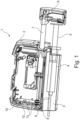
- the medical pump shown is a syringe pump 1, which is used, for example, in infusion therapy.
- the syringe pump 1 has a syringe housing 2 with a receiving compartment 3, which serves to accommodate a syringe 4 (shown here in outline) and to hold it if necessary.
- a syringe 4 filled with medication or similar with a syringe piston 5 for squeezing the syringe 4 is placed in the receiving compartment 3 and rests against a drive head 6 of the syringe pump 1.
- the drive head 6 is axially displaceable in order to actuate the syringe piston 5.
- a spindle 8 is connected to a spindle 8, more precisely a pull spindle, via a drive tube 7 mounted axially displaceably on the syringe housing 2.
- a conversion mechanism (not shown) is provided between the drive tube 7 and the spindle 8, which converts a rotary movement of the spindle 8 into a longitudinal movement of the drive head 6.
- the side of the syringe pump 1 and the roller bearing unit 9 which face in the direction of the drive head 6 or in a pulling direction are referred to below as the front side.
- the opposite side or direction of the syringe pump 1 and the roller bearing unit 9 which faces in the direction of the gear section 12 or in a pushing direction is referred to as the rear side.
- the spindle 8 is mounted on the syringe housing 2 in a rotatable and axially fixed manner by a double-row roller bearing unit 9.
- the double-row roller bearing unit 9 sits in a bearing seat 11 formed by a bearing plate 10.
- the bearing plate 10 is a housing section which serves to divide a gear section 12 in the syringe housing 2, in which drive gears 13 are arranged for driving the spindle 8.
- the drive gears 13 are also mounted on the bearing plate 10.
- An electric motor (not shown) is also provided for driving the drive gears 13.
- Fig. 2 is a perspective view of the double-row rolling bearing unit 9.
- a bearing outer ring of the rolling bearing unit 9 is in two parts and has a bearing bush 14 and a bearing cup 17.
- the bearing bush 14 forms an engagement contour on the outside in the form of a circumferential groove 15, into which snap hooks 16 of the bearing cup 17 engage.
- the snap hooks 16 serve as a preloading element, by means of which a defined preload/adjustment of the rolling bearing unit 9 is generated.
- the snap hooks 16 are designed in that the bearing cup 17 has, on its rear side (i.e., facing the bearing plate 10 of the syringe housing 2 when installed), sleeve-shaped end, slots 18 distributed at equal intervals around the bearing circumference, which run in the axial direction.
- the bearing cup 17 On its front side (i.e., facing away from the bearing plate 10 of the syringe housing when installed), the bearing cup 17 is curved radially inwards like a bowl and is open in the axial direction. Inside the bearing bush 14 and the bearing cup 17, a bearing core 19 is arranged, the front end of which, as shown in Fig. 2 shown, lies radially within an opening of the end of the bearing cup 17 facing away from the bearing plate 10.
- the rolling bearing unit 9 is mounted as a pre-assembled unit on the bearing plate 10 by the bearing bush 14 being pressed into the bearing plate 10.
- Fig. 3 shows a longitudinal section of the rolling bearing unit 9 of the Fig. 2 described example.
- a position of the rolling bearing unit 9 in the axial direction is determined by the fact that a collar or flange 20 formed by the bearing bush 14 and extending radially outwards rests on the rear side (ie on the side of the gear section 12 or on the side facing away from the drive head 6) of the bearing plate 10.
- a tensile load acting on the spindle 8 during a conveying operation ie a main load acting in the tensile direction, in the direction of the drive head 6) is supported on the bearing plate 10 by the flange 20.
- a chamfer 21 is provided around the bearing seat 11 on the rear side of the bearing plate 10 in order to facilitate pressing in or installing the bearing bush 14 on the circuit board 10.
- the bearing bush 14 Immediately to the front of the flange 20, the bearing bush 14 has a fitting section 22 which extends in the axial direction and via which the bearing bush 14 is pressed into the bearing seat 11 formed by the bearing plate 10 as described above. Through the press connection thus created, a pressure load acting on the spindle 8 (ie, secondary load acting in the direction of pressure or in the direction of the rear side) is transferred to the bearing plate 10.
- the bearing bush 14 forms a radially inwardly extending step, the circumferential groove 15 and an end portion extending in the axial direction towards the front.
- a radially inwardly extending collar is provided, which forms a first outer running surface 23 in the form of an angular contact ball bearing on its front side.
- the first outer running surface 23 supports first rolling elements 24, in this example balls, on the rear and radially on the outside.
- the bearing core 19 is arranged within the bearing bush 14 and is essentially sleeve-shaped and forms a spindle seat 30 on an inner circumferential surface for a connection to the spindle 8.
- the spindle seat 30 is preferably a slight clearance or transition fit, but can also be designed as a press fit.
- the bearing core 19 also has a radially outwardly projecting projection 25.
- a first inner running surface 26 in the form of an oblique groove ball bearing is formed for the first rolling elements 24, which is diametrically opposite the first outer running surface 23 in such a way that the first rolling elements 24 roll between the first inner running surface 26 and the first outer running surface 23 during a relative rotation of the bearing core 19 and the bearing bush 14.
- a second inner raceway 27 is designed in the manner of an oblique groove ball bearing in order to support second rolling elements 28, in this example balls, at the rear and radially inside.
- a second outer raceway 29 is designed in the manner of an oblique groove ball bearing on an inner side of the bearing cup 17, more precisely inside its bowl-shaped end, in order to support the second rolling elements 28 at the front and radially outside. This means that the second inner and the second outer raceway 27, 29 are opposite one another in such a way that the second rolling elements 28 rotate when the bearing core 19 and the bearing cup 17 between the second inner running surface 27 and the second outer running surface 29.
- Fig. 3 It can be clearly seen that the snap hooks 16 formed by the bearing cup 17 engage in the circumferential groove 15 of the bearing bush 14, thereby holding the rolling bearing unit 9 together.
- the free ends of the snap hooks 16, which engage in the circumferential groove 15, are bent radially inwards and form a ramp or mounting slope 37 at their rear end or rear face, by means of which the snap hooks 16 come into contact with the bearing bush 14 during an assembly process and are pressed outwards or bent up.
- the bearing core 19 and the rolling elements 24, 28 are inserted into the bearing bush 14 and the bearing cup 17 is pushed over the bearing bush 14 from the front, whereby the snap hooks 16 meet the front end of the bearing bush 14 and are elastically bent outwards by the front-side assembly bevels 37 until the snap hooks 16 finally snap into the circumferential groove 15 of the bearing bush 14.
- the snap hooks 16 cannot return completely elastically, but press against a front wall of the circumferential groove 15, whereby a defined preload or adjustment of the rolling bearing unit 9 is achieved.
- Fig. 3 It can be seen that the step of the bearing bush 14 formed immediately behind the fitting section 22 extends radially outwards beyond the outer circumference of the bearing cup 17 and thereby shields the snap hooks 16 in the axial direction. This prevents a disruptive body from reaching behind the snap hooks 16, particularly in a pre-assembled, uninstalled state of the rolling bearing unit 9, and these being opened unintentionally, which would cause the rolling bearing unit 9 to fall apart.
- the tensile load thus acting on the bearing cup 17 is transferred via the snap hooks 16 to the bearing bush 14 and from there via the friction in the press connection between the bearing bush 14 and the bearing plate 10 and via the flange 20 to the bearing plate 10.
- the flange 20 is required because relatively high forces act on the spindle 8 during conveying operation.
- a comparatively low pressure load acts on the spindle 8, which is supported via the spindle seat 30 or, if necessary, via a front face 36 (in Fig. 3 right) of the bearing core 19 to the bearing core 19.
- the first and second rolling elements 24, 28 are designed according to the different loads in the tensile and compressive directions, so that smaller balls are selected as the first rolling elements 24 (e.g. with a diameter of 2 mm) than for the second rolling elements 28 (e.g. with a diameter of 3 mm).
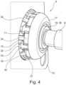
- Fig. 4 shows a perspective view of a rolling bearing unit 9 according to an embodiment of the invention.
- the structure of the syringe pump 1, the rolling bearing unit 9 itself and its installation situation correspond to a large extent to that of the above example, which is why only differences between the embodiment and the above example are explained below in order to avoid redundant descriptions.
- the snap hooks 16 are arranged at equal intervals around the circumference of the bearing cup 17.
- the snap hooks 16 are arranged in Fig. 4 illustrated embodiment from substantially cross-shaped sections made of sheet metal, plastic or other elastically deformable materials (in particular from the same material and in one piece with the rest of the bearing cup).
- the foot 31 of this cross is integrally connected to the bowl-shaped end of the bearing cup 17 and extends axially towards the bearing plate 10 or in the compression direction.
- Two arms 32 of the cross extend on either side of the foot 31 in the circumferential direction or perpendicular thereto and are bent radially inwards with their free ends in order to engage in the circumferential groove 15.
- a head 33 of the cross basically represents an extension of the foot 31 beyond the arms 32 and is bent radially outwards. The free end of the head 33 rests against an inner circumferential surface of the bearing seat 11 formed in the bearing plate 10, whereby the cross-shaped snap hooks 16 are elastically pressed radially inwards when installed or are at least held in the position engaging in the circumferential groove 15.
- the head 33 of the cross serves as a hold-down device to secure the engagement of the arms 32 of the cross in the circumferential groove 15, whereby their snapping out can be prevented even under a high tensile load.
- the sleeve-shaped section of the bearing cup 17 extending in the axial direction forms elastic support elements 34. These are arranged around the circumference of the bearing cup 17, alternating with the snap hooks 16, at equal distances from one another.
- the support elements 34 are bent obliquely radially outwards in such a way that they are supported on the outside on the forward-facing surface of the bearing plate 10, on the one hand to realize self-locking of the rolling bearing unit 9 in the bearing plate 10 and on the other hand to transfer forces to the bearing plate 10 in a form-fitting manner in the direction of pressure, instead of doing so, as in the example according to Fig. 2 and Fig. 3 , exclusively frictionally engaged via the press connection with the bearing seat 11.
- the support elements 34 are integrally connected to the bowl-shaped end of the bearing cup 17 via a widened base extending parallel to the bearing axis and also have a narrower free end connected to the base, which is bent radially outward as described above in order to be supported on the bearing plate 10. Due to the manufacturing process, the base of a support element 34 lies between the feet 31 of two cross-shaped snap hooks 16 and the base ends in the axial direction just before two arms 32 of two snap hooks 16. For example, this enables a simple, uniform cutting width in order to introduce the snap hooks 16 and the support elements 34 into the bearing cup 17 manufactured in one piece. It should be noted that in this special embodiment, both the snap hooks 16 and the support elements 34 are provided.
- Fig. 5 shows a longitudinal section through the rolling bearing unit 9 of the embodiment along a plane which runs through the bearing axis L and intersects support elements 34 which are diametrically opposite one another with respect to the rolling bearing unit 9.
- the bearing plate 10 is slightly bevelled on the forward-facing peripheral edge of the bearing seat 11 in order to enable the free ends of the support elements 34 to rest better on the bearing plate 10.
- the support elements 34 are elastic, they can spring in to enable the bearing to be fitted into the bearing seat 11 of the bearing plate 10 from the side of the gear section 12. In the end position or when the installed state is reached, the support elements 34 leave the bearing seat 11 and snap outwards in order to be supported axially on the bearing plate 10.
- a snap hook 16 can be seen in the upper part of the housing (at the top), the head 33 of which rests in a radial direction against the inner circumferential surface of the bearing seat 11 of the bearing plate 10.
- the fitting section 22 of the bearing bush 14 is smaller than that of the example according to Fig. 2 and Fig. 3 is relatively short and does not extend in the axial direction beyond the bearing seat 11 of the bearing plate 10, so that a section of the bearing seat 11 is exposed, on which the heads 33 of the snap hooks 16 can be supported.
- an arm 32 of the snap hook 16 can be seen, which fits into the circumferential groove 15 of the Bearing bush 14 engages and also forms a ramp or mounting slope 37 on its rear end face, by means of which the snap hook 16 is pressed radially outwards when the bearing cup 17 is snapped onto the bearing bush 14.
- the geometry of the bearing cup 9 is expanded in such a way that after pressing into the bearing seat 11, retaining tabs or support elements 34 engage and the bearing is also positively locked in the pressure direction and not just frictionally locked, as in the example according to Fig. 2 and Fig. 3 , secure.
- the hold-down devices 33 prevent the locking geometries (snap hooks 16) on the bearing cup 17 from opening under tensile forces Z.
- Fig. 4 and Fig. 5 also show the rolling bearing unit 9, to which both the spindle 8 and one of the drive gears 13 are already attached. This installation situation is equally applicable to the example according to Fig. 2 and Fig. 3 transferable.
- the rolling bearing unit 9 according to the example described above Fig. 2 and Fig. 3 is particularly simple and cost-effective and is particularly advantageous in the case of relatively low loads. However, if the rolling bearing unit 9 is subjected to higher loads, the rolling bearing unit 9 according to the embodiment described above may be advantageous, since it has additional securing and fastenings through the hold-down devices 33 and support elements 34 in order to absorb higher loads without increasing the number of components required, the effort of (pre-)assembly or installation of the rolling bearing unit 9 according to the invention in the syringe pump 1.
Landscapes
- Engineering & Computer Science (AREA)
- General Engineering & Computer Science (AREA)
- Mechanical Engineering (AREA)
- Health & Medical Sciences (AREA)
- Vascular Medicine (AREA)
- Anesthesiology (AREA)
- Biomedical Technology (AREA)
- Heart & Thoracic Surgery (AREA)
- Hematology (AREA)
- Life Sciences & Earth Sciences (AREA)
- Animal Behavior & Ethology (AREA)
- General Health & Medical Sciences (AREA)
- Public Health (AREA)
- Veterinary Medicine (AREA)
- Rolling Contact Bearings (AREA)
- Support Of The Bearing (AREA)
- Mounting Of Bearings Or Others (AREA)
Description
- Die vorliegende Erfindung betrifft eine doppelreihige Wälzlagereinheit einer medizinischen Pumpe mit einem Lagerkern, welcher eine erste, in eine Axialrichtung gewandte Innenlauffläche für erste Wälzkörper sowie eine zweite, der ersten Innenlauffläche in Axialrichtung entgegengesetzt angeordnete Innenlauffläche für zweite Wälzköper ausbildet, einer Lagerbuchse, welche an einem Gehäuseabschnitt anbringbar ist und eine der ersten Innenlauffläche gegenüberliegende erste Außenlauffläche ausbildet, und einem Lagertopf, welcher eine der zweiten Innenlauffläche gegenüberliegende zweite Außenlauffläche ausbildet. Ferner betrifft die vorliegende Erfindung eine medizinische Pumpe, vorzugsweise Spritzenpumpe, mit einer entsprechenden doppelreihigen Wälzlagereinheit.
- Medizintechnische Therapien erfordern heute hochpräzise medizinische Pumpen, welche hohe Anforderungen unter anderem an Bauraum, Gewicht, Bedienungs- und Funktionssicherheit sowie Genauigkeit haben. Entsprechend unterliegen die einzelnen mechanischen Komponenten engen Toleranzen, hohen Miniaturisierungsanforderungen und müssen ggf. aufwändig eingebaut und eingestellt werden.
- Beispielsweise werden in der Infusionstherapie zur Applikation von Flüssigkeiten häufig Spritzenpumpen eingesetzt, wie z.B. die Perfusor® Space von B.Braun, welche flexible, sichere Therapien ermöglichen und hochpräzise arbeiten müssen, um auch minimale Flüssigkeitsmengen genau dosieren zu können. In einer solchen Spritzenpumpe wird eine mit einer solchen Flüssigkeit gefüllte Spritze in die Pumpe eingelegt und die Spritze wird anschließend über einen Antriebskopf mit einer definierten Förderrate ausgedrückt (Förderbetrieb), welcher über eine Spindel angetrieben wird. Dabei werden über einen langen Zeitraum, bis zu mehreren Tagen, auf die Spindel hohe Axiallasten bei kleinen Drehzahlen aufgebracht. Muss die Spritze gewechselt werden, wird der Antriebskopf schnell, d.h. in wenigen Sekunden, mit hohen Drehzahlen und sehr geringen Axiallasten zurückgefahren (Rückstellbetrieb). Aufgrund der hohen Genauigkeitsanforderungen werden entsprechend hohe Anforderungen an Toleranzen bei der Lagerung der Spindel gestellt.
- Derzeit werden für derartige Präzisionsanwendungen Lagerkonzepte verwendet, welche aus einer Vielzahl einzelner Lager bestehen. Die für die einzelnen Lager notwendigen Bauelemente und -gruppen müssen einzeln eingelagert, kommissioniert und eingebaut werden. Die Lagerungen werden während der Montage der Pumpe aufwändig eingestellt, was zusätzlich dadurch verschärft wird, dass der zur Verfügung stehende Bauraum sehr gering ist und hohe Miniaturisierungsanforderungen vorliegen. Insbesondere ist ein Befestigen der Lagersitze mittels Schrauben aufgrund des beschränkten Bauraums der Pumpe nur eingeschränkt oder gar nicht möglich. Entsprechend ist der Montageaufwand der Pumpe hoch und es sind kostenintensive und fehleranfällige Einstellarbeiten notwendig, was einen reproduzierbar präzisen Einbau der Lagerungen erschwert. Ferner weisen diese Lagerungen ggf. mangelnde Bewegungsfreiheitsgrade auf, wodurch ein Verklemmen der Lagerung insbesondere während des Einbaus derselben auftreten kann. Zudem liegt in den aktuell verwendeten Lagerkonzepten hohe Reibung vor.
- Beispielsweise ist aus
DE 80 09 464 U1 ein Lager mit einer Tragplatte, einem Außengehäuse und einem Innenring sowie mit zwei axial hintereinander angeordneten Kugelreihen offenbart. Der Innenring umfasst zwei tiefgezogene Blechschalen mit jeweils einer rinnenförmigen Innenlauffläche; und der Außenring umfasst tiefgezogene Blechteile mit rinnenförmigen Außenlaufflächen. Eines der Blechteile weist einen axial nach außen vorspringenden Ringsteg auf, der den Stirnrand des anderen Blechteils klemmend übergreift.DE 80 09 464 U1 offenbart eine doppelreihige Wälzlagereinheit gemäß dem Oberbegriff des Anspruchs 1. -
DE 10 2006 034729 B3 betrifft ein zweireihiges Pendelrollen- oder -kugellager, bei dem Wälzkörper zwischen zwei Innenringlaufbahnen und zwei Außenringlaufbahnen angeordnet sind, wobei sowohl die Innenringlaufbahnen als auch die Außenringlaufbahnen durch Bleche gebildet werden, wobei die Innenringlaufbahnen von zwei Stützkörpern aufgenommen werden und wobei die beiden Stützkörper mit Mitteln ausgestattet sind, die ein formschlüssiges Verbinden beider Stützkörper zum unverschieblichen Zusammenhalt in axialer Richtung ermöglichen. Die Mittel sind nach Art eines Reißverschlusses ausgeführt, indem nämlich hakenförmig ausgebildete Vorsprünge und Hinterschnitte in den beiden miteinander zu verbindenden Stützkörpern zusammenwirken. -
US 2010/284643 A1 offenbart ein Wälzlager mit einem Lagerinnen- und Lageraußenring, bei dem mindestens einer der Lagerringe in zwei formgleiche Ringhälften geteilt ist. Rastelemente sind an einem radial inneren oder radial äußeren Ringteil angeformt. Segmentartige und schalenförmige Vorsprünge ragen axial über das Ringteil an einem Teil seiner Umfangserstreckung hinaus. Die Vorsprünge sind in einer anderen Radialebene zu den Rastgliedern angeordnet, die in Umfangsrichtung durch segmentartige Vertiefungen begrenzt sind und die Vorsprünge der einen Ringhälfte in die formkomplementär ausgebildeten Vertiefungen der anderen Ringhälfte eingreifen, sodass sich die Vorsprünge und das Ringteil in axialer Richtung überlappen und die Rastglieder der einen Ringhälfte in Aussparungen eingreifen, die im anderen Ringteil angeordnet sind. - Demgemäß besteht die Aufgabe der vorliegenden Erfindung darin, aus dem Stand der Technik bekannte Nachteile zu beheben oder zu reduzieren, und insbesondere darin, eine Montage von medizinischen Pumpen zu vereinfachen, sicherer, präziser und reproduzierbar zu machen und die Fertigungskosten zu senken.
- Die der Erfindung zugrunde liegende Aufgabe wird durch eine doppelreihige Wälzlagereinheit einer medizinischen Pumpe, vorzugsweise Spritzenpumpe, gelöst, mit einem Lagerkern, welcher eine erste, teilweise in eine Axialrichtung gewandte Innenlauffläche für erste Wälzkörper sowie eine zweite, der ersten Innenlauffläche teilweise in Axialrichtung entgegengesetzt angeordnete Innenlauffläche für zweite Wälzköper ausbildet. Ferner hat die Pumpe eine Lagerbuchse, welche an einem Gehäuseabschnitt bzw. einer Lagerplatte anbringbar ist und eine der ersten Innenlauffläche gegenüberliegende erste Außenlauffläche für die ersten Wälzkörper ausbildet, sowie einen Lagertopf oder Lagerdeckel, welcher eine der zweiten Innenlauffläche gegenüberliegende zweite Außenlauffläche für die zweiten Wälzkörper ausbildet. Dabei ist zumindest ein Vorspannelement vorgesehen, welches den Lagertopf mit der Lagerbuchse mit einer definierten Vorspannung/Anstellung koppelt, um die handhabbar vormontierte, doppelreihige Wälzlagereinheit auszubilden. Vorzugsweise ist die vorgespannte Wälzlagereinheit vorspannungseinstellfrei in der Pumpe einbaubar.
- An der Wälzlagereinheit sind ferner radial nach außen vorstehende Stützelemente ausgebildet, welche zur Abstützung in einer zweiten Lastrichtung an dem Gehäuseabschnitt vorgesehen sind. Die Stützelemente sind elastisch, um radial nach innen einfedern zu können. Insbesondere ist die erste Lastrichtung eine Nebenlastrichtung, in welcher Kräfte beispielsweise bei einem Rückstellbetrieb der Spritzenpumpe wirken. Durch radial nach innen einfederbare Stützelemente wird dabei der Einbau der Wälzlagereinheit in der Pumpe vereinfacht, da diese dabei aus dem Weg gedrückt werden können. Ferner kann ein Zurückfedern der Stützelemente als ein Signal für ein Erreichen der korrekten Einbauposition dienen.
- In anderen Worten wird eine angestellte Lagerung in X- oder O-Anordnung bereitgestellt, welche durch zumindest ein Vorspannelement als vormontierte und vorgespannte, spielfreie Einheit bereitgestellt ist. Eine Lagerung mit X-Anordnung bedeutet im Rahmen der vorliegenden Erfindung, dass zwei kombinierte Schräglagerabschnitte derart spiegelbildlich zueinander angeordnet sind, dass Drucklinien (Richtungen, entlang welcher in einer Reihe von Wälzkörpern Kräfte übertragen werden) sich in der entsprechenden Lagerachse schneiden und dabei in Richtung der jeweils gegenüberliegenden Reihe von Wälzkörpern bzw. dem gegenüberliegenden Schräglagerabschnitt weisen. Bei einer O-Anordnung verlaufen diese Drucklinien in entgegengesetzte Richtung, also in Richtung radial innen weg von dem gegenüberliegenden Schräglagerabschnitt. Eine solche Lagerung ermöglicht eine sehr enge, präzise Führung einer Welle oder Spindel der medizinischen Pumpe. Ferner ist die Anzahl der benötigten Bauteile gegenüber einer konventionellen Lagerung deutlich reduziert, sodass die Kosten reduziert sind. Als Wälzkörper kommen beispielsweise Kegel, Rollen oder Nadeln, sowie vorzugsweise Kugeln, Tonnen und Pendelrollen in Frage. Dabei können die ersten und zweiten Wälzlager abhängig von den auftretenden Belastungen jeweils unterschiedlich geformt und/oder dimensioniert sein. Die Wälzlagereinheit ist vorzugsweise lebensdauergeschmiert.
- Vorzugsweise ist die Lagerbuchse über einen Passungsabschnitt an dem Gehäuseabschnitt anbringbar ist, wobei der Lagertopf entlang der Axialrichtung neben dem Passungsabschnitt und diesen nicht überlappend angeordnet ist. In anderen Worten ausgedrückt sind der Passungsabschnitt und der Lagertopf im zusammengebauten Zustand der Lagereinheit vorzugsweise in Axialrichtung zueinander versetzt bzw. zueinander beabstandet angeordnet. Weiter vorzugsweise ist das zumindest eine Vorspannelement ein elastischer, die Lagerbuchse zumindest teilweise umgreifender Abschnitt des Lagertopfs. In anderen Worten ausgedrückt sind der Lagertopf und das Vorspannelement stoffeinstückig ausgebildet. Insbesondere ist der Lagertopf an seinem der Lagerbuchse zugewandten Ende geschlitzt und zwischen den Schlitzen stehenbleibende Stege sind elastisch biegbar, um mehrere Vorspannelemente zu bilden. Vorteile dieser Ausgestaltung liegen darin, dass ein radialer Bauraum der Lagereinheit verringert werden kann und/oder die Montage derselben vereinfacht ist und/oder die Bearbeitung des Lagersitzes einfacher ist und/oder das zumindest eine Vorspannelement hinsichtlich seiner Biegbarkeit und Handhabbarkeit vorteilhaft ausgebildet werden kann.
- Eine erfindungsgemäße Wälzlagereinheit ermöglicht, den Aufwand deren Einbaus in die Pumpe sowie der zugehörigen Vorbereitung deutlich zu reduzieren. Anstelle mehrerer verschiedener Lager kann die Wälzlagereinheit als einzelne, vormontierte Baugruppe transportiert, gelagert und kommissioniert werden und anschließend in die Pumpe eingebaut werden, ohne dass ein Arbeitsschritt zur Einstellung der Vorspannung der Lagerung vorgesehen werden muss. Beispielsweise kann die Wälzlagereinheit auf eine Welle oder Spindel einer Pumpe aufgepresst werden und über eine entweder an dem Lagertopf oder an der Lagerbuchse vorgesehenen Passungsabschnitt an dem Pumpengehäuse befestigt werden. Alternativ kann die Wälzlagereinheit beispielsweise in das Pumpengehäuse eingeklebt, eingepresst oder eingeschraubt werden. Hierfür kann z.B. an einem Außenumfang der Wälzlagereinheit ein Gewinde bereitgestellt sein.
- Es sind zudem verschiedene Ausführungen des zumindest einen Vorspannelements denkbar. Es kann als separates, elastisches Bauteil bereitgestellt werden, wie z.B. als eine in die Wälzlagereinheit eingelegte Zug- oder Druckfeder, oder auch als eine Gruppe von separaten, elastischen Bauteilen, die vorzugsweise in gleichen Abständen rund um den Umfang der Wälzlagereinheit verteilt angeordnet sind. Denkbar ist auch, ein an dem Lagertopf und/oder der Lagerbuchse vorgesehenes Gewindeelement als das Vorspannelement bereitzustellen und somit den Lagertopf und die Lagerbuchse durch ein Schraubgewinde, insbesondere ein Einstellgewinde, miteinander zu verspannen.
- Es hat sich als besonders zweckmäßig erwiesen, dass das zumindest eine Vorspannelement zumindest ein elastischer Abschnitt des Lagertopfs oder der Lagerbuchse ist, vorzugsweise eine Anzahl von Schnapphaken. Weiter vorzugsweise ist eine Anzahl von Vorspannelementen in gleichen Abständen rund um den Umfang der Lagerbuchse oder des Lagertopfes verteilt. Dieses zumindest eine Vorspannelement umgreift entsprechend die Lagerbuchse bzw. den Lagertopf zumindest teilweise oder greift darin ein. Somit ist das zumindest eine Vorspannelement mit anderen Bauteilen der Wälzlagereinheit integral verbunden, sodass die Anzahl der benötigten Bauteile reduziert und das Gewicht der Wälzlagereinheit optimiert werden kann, sowie Fertigungskosten gesenkt werden können. Insbesondere ermöglicht die Ausgestaltung des Vorspannelements als ein ein-/umgreifendes elastisches Bauteil wie z.B Schnapphaken, dass die Vorspannung der Wälzlagereinheit durch diese Elastizität und eine konstruktive Ausgestaltung festgelegt ist. Besonders aufgrund der durch den beschränkten Bauraum bedingten Miniaturisierung der Wälzlagereinheit ist dies eine erhebliche Erleichterung. Beispielsweise gegenüber einer Einstellung durch ein Einstellgewinde hat dies zum Vorteil, dass die Vormontage der Wälzlagereinheit deutlich schneller erfolgt und die hohen Anforderungen an Toleranzen zuverlässig eingehalten werden, da der Prozess besser reproduzierbar ist, d. h., weniger menschlichen Fehlern unterliegt. Dadurch werden die Fertigungskosten erheblich gesenkt.
- Eine vorteilhafte Ausgestaltung der erfindungsgemäßen Wälzlagereinheit sieht vor, dass die ersten Wälzkörper und ersten Laufflächen mit den zweiten Wälzkörpern und zweiten Laufflächen eine X-angeordnete Lagerung bilden. Insbesondere wird bevorzugt, dass die ersten und/oder zweiten Wälzkörper eine Taumelbewegung des Lagerkerns relativ zu dem Lagertopf und der Lagerbuchse ermöglichen (Taumelfreiheit), vorzugsweise in einem Winkelbereich von +/-1° um die Lager- bzw. Längsachse.
- Eine Taumelfreiheit in der Wälzlagereinheit ist wichtig für einen möglichst schnellen, reproduzierbaren und sicheren Einbau der erfindungsgemäßen Wälzlagereinheit, da die Welle oder Spindel der medizinischen Pumpe in der Regel nicht perfekt koaxial zu der Lagerachse und/oder zu einem an dem Gehäuseabschnitt bereitgestellten Lagersitz eingesetzt werden kann. Bei dem Einbau, insbesondere bei einer Handhabung der Spindel oder Welle kommt es entsprechend zu geringfügigen Winkelabweichungen, welche durch die Wälzlagereinheit zugelassen werden müssen. Eine X-Anordnung der ersten und zweiten Wälzlagerreihen hat ein relativ großes Kippspiel, d. h., sie ist dazu geeignet, geringfügige Winkelabweichungen zwischen dem Lagerkern sowie der Lagerbuchse und dem Lagertopf zuzulassen, ohne sich zu verklemmen. Ferner werden nach dieser bevorzugten Ausführung der Erfindung abgerundete Wälzkörper, d. h., Tonnen, Pendelrollen oder vorzugsweise Kugeln eingesetzt, damit das Taumeln möglich ist.
- Sinnvollerweise kann die Lagerbuchse einen radial nach außen vorstehenden Flansch ausbilden, welcher zur Abstützung in einer ersten Lastrichtung an dem Gehäuseabschnitt vorgesehen ist.
- Da die Wälzlagereinheit derart eingebaut wird, dass der Flansch an dem Gehäuseabschnitt anliegt, wird durch diesen die axiale Einbauposition der Wälzlagereinheit festgelegt. Dies ist für den präzisen und reproduzierbaren Einbau der Wälzlagereinheit in der medizinischen Pumpe wichtig. Zudem dient der Flansch als Abstützung der von der Wälzlagereinheit auf den Gehäuseabschnitt übertragenen axialen Kräfte in der ersten Lastrichtung, welche vorzugsweise einer Hauptlastrichtung entspricht, beispielsweise bei einem Förderbetrieb der medizinischen Spritzenpumpe. Wenn sowohl der Flansch als auch die Stützelemente vorgesehen sind, ist die Wälzlagereinheit axial in beide Richtungen formschlüssig gesichert.
- Die erfindungsgemäße Wälzlagereinheit ist derart ausgebildet, dass das zumindest eine Vorspannelement einen oder mehrere Niederhalter aufweist, welche dazu konfiguriert sind, sich radial nach außen an dem Gehäuseabschnitt abzustützen, um das zumindest eine Vorspannelement in eine zugehörige Eingriffskontur zu drücken, wenn das doppelreihige Wälzlager in dem Gehäuseabschnitt eingebaut ist. Dies ist insbesondere vorteilhaft, wenn als Vorspannelemente Schnapphaken vorgesehen sind, welche mit einem radial nach innen abstehenden Vorsprung zumindest teilweise die Lagerbuchse bzw. den Lagertopf umgreifen oder darin eingreifen, wobei die Schnapphaken bei der (Vor-) Montage und Demontage der Wälzlagereinheit radial nach außen aufgebogen werden müssen. Die Niederhalter verhindern das Aufbiegen nach außen der Schnapphaken, wenn die Wälzlagereinheit in der Pumpe eingebaut ist, und dienen somit als eine Selbstsicherung gegen ein Öffnen der Lagereinheit im Betrieb. Dies ist insbesondere dann vorteilhaft, wenn die medizinische Pumpe eine Spritzenpumpe mit einer Zugspindel ist, da bei einer solchen bei einem Förderbetrieb hohe Zugkräfte auf die Wälzlagereinheit aufgebracht werden, durch welche sich die Schnappverbindung ggf. ungewollt öffnen könnte.
- Alternativ ist es denkbar, einen Niederhalter, insbesondere in Form einer umlaufenden, nach radial innen vorstehenden Auskragung oder Stufe, an dem Gehäuseabschnitt vorzugsehen, welcher von radial außen gegen die Vorspannelemente oder Schnapphaken drückt. Je nachdem, wie der Gehäuseabschnitt strukturell ausgestaltet ist und welchen Anforderungen er ferner unterliegt, ist diese Lösung kostengünstiger als die, bei welcher die Niederhalter von den Vorspannelementen ausgebildet sind.
- Zusammenfassend ist anzumerken, dass die erfindungsgemäße Wälzlagereinheit in Ihrer einfachsten Form Vorspannelemente vorsieht. Die Stützabschnitte sowie die Niederhalter sind vorteilhafte Ausgestaltungen der Erfindung, welche sowohl einzeln als auch kombiniert und ggf. einstückig ausgebildet vorgesehen werden können, um vorstehend beschriebene, vorteilhafte Effekte zu erzielen.
- Die Wälzlagereinheit ist spielfrei und kompakt, ihr Einbau in die medizinische Pumpe ist sehr einfach und reproduzierbar, da keine Einstellarbeiten oder Prüfungen der Vorspannung notwendig sind, und die Stückkosten sind gering, da die einzelnen Komponenten der Wälzlagereinheit günstig durch Volumenprozesse fertigbar sind, wie z.B. durch Spritzgießen aus Tribo-Kunststoff. Ebenso ist die (Vor-)Montage der Wälzlagereinheit an sich, insbesondere in der Ausführung mit Schnapphaken, schnell, kostengünstig und reproduzierbar, da die Komponenten, insbesondere die Schnapphaken, selbsteinstellend sind.
- Die Wälzlagereinheit wird vormontiert, indem in die Lagerbuchse oder das Lagergehäuse die Wälzkörper, insbesondere Kugeln, und der Lagerkern eingelegt werden, welche anschließend durch ein Anbringen, insbesondere Aufschnappen, des Lagertopfs oder Lagerdeckels definiert spielfrei verspannt werden. Dabei drückt der Lagertopf gegen die Kugeln, welche einen Anschlag bzw. eine Begrenzung des Vorspannwegs ausbilden. Ferner werden die Kugeln bei dem Aufschnappen des Lagertopfs in ihre für den Betrieb vorgesehenen Positionen gedrückt bzw. kommen in ihren vorbestimmten Laufflächen/Laufbahnen zu liegen. Dadurch wird insbesondere ein X-spielfrei verspanntes Lagerelement ausgebildet. Das heißt, die Vorspannung wird durch die Montage der Wälzlagereinheit an sich erreicht. Der Lagertopf, insbesondere in der Ausführung mit Schnapphaken, ist durch seine Formgebung bedingt federnd und lässt sich bei der Montage in eine Rastgeometrie einhaken. Dadurch wird eine dauerhafte (Vorspann-)Kraft auf den drehbaren Innenläufer/Lagerkern aufgebracht. Sowohl die Montage der Wälzlagereinheit an sich als auch deren Einbau in der Pumpe sind leicht automatisierbar.
- Des Weiteren wird die der Erfindung zugrunde liegende Aufgabe durch eine medizinische Pumpe, vorzugsweise eine Spritzenpumpe, gelöst, welche eine Spindel, vorzugsweise eine Zugspindel, aufweist, die durch eine doppelreihige Wälzlagereinheit gemäß der vorstehenden Beschreibung drehbar und axialfest in einem Gehäuseabschnitt der medizinischen Spritzenpumpe gelagert ist.
- Die vormontierte Wälzlagereinheit kann in der Pumpe mittels eines ggf. miniaturisierten Einpresswerkzeugs eingebaut werden. Dabei wird sie in eine beliebige Bohrung mit einer entsprechenden Passung eingepresst. Die Festigkeit der Verbindung wird durch die Passung zwischen der Bohrung und der Lagereinheit und durch die Scherfestigkeit eines Lagerbundes (Passungsabschnitts) definiert.
- Nachfolgend wird die vorliegende Erfindung anhand beispielhafter Ausführungsformen mit Referenz auf die beigefügten Zeichnungen beschrieben, die Erfindung soll jedoch nicht darauf begrenzt sein. Dabei werden für gleiche Elemente dieselben Bezugszeichen verwendet.
-
Fig. 1 zeigt eine Spritzenpumpe, in welcher eine doppelreihige Wälzlagereinheit eingebaut ist. -
Fig. 2 zeigt eine perspektivische Ansicht der doppelreihigen Wälzlagereinheit nach einem Beispiel zum Verständnis der Erfindung. -
Fig. 3 zeigt eine Längsschnittansicht der doppelreihigen Wälzlagereinheit nach dem Beispiel nachFig. 2 . -
Fig. 4 zeigt eine perspektivische Ansicht der doppelreihigen Wälzlagereinheit nach einer Ausführungsform der Erfindung. -
Fig. 5 zeigt eine Längsschnittansicht der doppelreihigen Wälzlagereinheit nach der Ausführungsform der Erfindung. - Bei der in
Fig. 1 dargestellten medizinischen Pumpe handelt es sich um eine Spritzenpumpe 1, welche beispielsweise bei einer Infusionstherapie zum Einsatz kommt. Die Spritzenpumpe 1 weist ein Spritzengehäuse 2 mit einem Aufnahmefach 3 auf, welches dazu dient, eine Spritze 4 (hier schemenhaft angedeutet) aufzunehmen und gegebenenfalls zu halten. Bei Betrieb der Spritzenpumpe 1 ist eine mit Medikamenten o.Ä. gefüllte Spritze 4 mit einem Spritzenkolben 5 zum Ausdrücken der Spritze 4 in das Aufnahmefach 3 eingelegt und liegt an einem Antriebskopf 6 der Spritzenpumpe 1 an. Der Antriebskopf 6 ist axial verschiebbar, um den Spritzenkolben 5 zu betätigen. Dabei ist er über ein axial verschiebbar an dem Spritzengehäuse 2 gelagertes Antriebsrohr 7 mit einer Spindel 8, genauer einer Zugspindel, verbunden. Zwischen dem Antriebsrohr 7 und der Spindel 8 ist ein Wandlungsmechanismus (nicht dargestellt) vorgesehen, welcher eine Drehbewegung der Spindel 8 in eine Längsbewegung des Antriebskopfes 6 wandelt. - Nachfolgend werden zur besseren Orientierung die Seite der Spritzenpumpe 1 und der Wälzlagereinheit 9, welche in Richtung des Antriebskopfes 6 bzw. in eine Zugrichtung betrachtet gewandt sind, als Vorderseite bezeichnet. Die dazu entgegengesetzte Seite bzw. Richtung der Spritzenpumpe 1 und der Wälzlagereinheit 9, welche in Richtung des Getriebeabschnitts 12 bzw. in eine Druckrichtung gewandt ist, wird als Rückseite bezeichnet.
- Die Spindel 8 ist durch eine doppelreihige Wälzlagereinheit 9 drehbar und axialfest an dem Spritzengehäuse 2 gelagert. Nach dieser Ausführungsform sitzt die doppelreihige Wälzlagereinheit 9 in einem von einer Lagerplatte 10 ausgebildeten Lagersitz 11. Die Lagerplatte 10 ist ein Gehäuseabschnitt, welcher dazu dient, in dem Spritzengehäuse 2 einen Getriebeabschnitt 12 abzuteilen, in welchem Antriebszahnräder 13 zum Antreiben der Spindel 8 angeordnet sind. Die Antriebszahnräder 13 sind ebenfalls an der Lagerplatte 10 gelagert. Zum Antreiben der Antriebszahnräder 13 ist ferner ein Elektromotor (nicht dargestellt) vorgesehen.
- Das nachfolgend mit Verweis auf
Fig. 2 undFig. 3 beschriebene Beispiel dient lediglich zum Verständnis der anschließend mit Verweis aufFig. 4 und5 beschriebenen Ausführungsform der vorliegenden Erfindung. -
Fig. 2 ist eine perspektivische Darstellung der doppelreihigen Wälzlagereinheit 9. Ein Lageraußenring der Wälzlagereinheit 9 ist zweiteilig und weist eine Lagerbuchse 14 und einen Lagertopf 17 auf. Die Lagerbuchse 14 bildet außenseitig eine Eingriffskontur in Form einer Umfangsnut 15 aus, in welche Schnapphaken 16 des Lagertopfs 17 eingreifen. Die Schnapphaken 16 dienen dabei als ein Vorspannelement, durch welches eine definierte Vorspannung/Anstellung der Wälzlagereinheit 9 erzeugt wird. Die Schnapphaken 16 sind dadurch ausgebildet, dass der Lagertopf 17 an seinem rückseitigen (d. h., im eingebauten Zustand der Lagerplatte 10 des Spritzengehäuses 2 zugewandten), hülsenförmig ausgebildeten Ende in gleichen Abständen rund um den Lagerumfang verteilte Schlitze 18 aufweist, welche in Axialrichtung verlaufen. Zwischen den Schlitzen 18 bleiben elastische Stege, die Schnapphaken 16, stehen. An seinem vorderseitigen (d. h., im eingebauten Zustand der Lagerplatte 10 des Spritzengehäuses abgewandten) Ende ist der Lagertopf 17 schüsselartig nach radial innen gekrümmt und in Axialrichtung offen. Innerhalb der Lagerbuchse 14 und des Lagertopfs 17 ist ein Lagerkern 19 angeordnet, dessen vorderseitiges Ende, wie inFig. 2 dargestellt, radial innerhalb einer Öffnung des der Lagerplatte 10 abgewandten Endes des Lagertopfs 17 liegt. Die Wälzlagereinheit 9 ist als eine vormontierte Baugruppe an der Lagerplatte 10 montiert, indem die Lagerbuchse 14 in die Lagerplatte 10 eingepresst ist. -
Fig. 3 zeigt einen Längsschnitt der Wälzlagereinheit 9 des inFig. 2 beschriebenen Beispiels. Eine Position der Wälzlagereinheit 9 in Axialrichtung ist dadurch festgelegt, dass ein von der Lagerbuchse 14 ausgebildeter, sich radial nach außen erstreckender Kragen oder Flansch 20 rückseitig (d. h., an der Seite des Getriebeabschnitts 12 bzw. an der dem Antriebskopf 6 abgewandten Seite) an der Lagerplatte 10 anliegt. Ferner wird durch den Flansch 20 eine während eines Förderbetriebs auf die Spindel 8 wirkende Zugbelastung (d. h., eine in Zugrichtung, in Richtung hin zu dem Antriebskopf 6 wirkende Hauptlast) an der Lagerplatte 10 abgestützt. Rund um den Lagersitz 11 an der Rückseite der Lagerplatte 10 ist eine Fase 21 vorgesehen, um ein Einpressen bzw. einen Einbau der Lagerbuchse 14 an der Leiterplatte 10 zu erleichtern. Unmittelbar vorderseitig des Flanschs 20 weist die Lagerbuchse 14 einen Passungsabschnitt 22 auf, welcher sich in Axialrichtung erstreckt und über welchen die Lagerbuchse 14 wie vorstehend beschrieben in den durch die Lagerplatte 10 ausgebildeten Lagersitz 11 eingepresst ist. Durch die so erzeugte Pressverbindung wird eine auf die Spindel 8 wirkende Druckbelastung (d.h., in Druckrichtung bzw. in Richtung der Rückseite wirkende Nebenlast) auf die Lagerplatte 10 übertragen. Unmittelbar hinter dem Passungsabschnitt 22 bildet die Lagerbuchse 14 in der folgenden Reihenfolge eine radial nach innen verlaufende Stufe, die Umfangsnut 15 und einen sich in Axialrichtung zu der Vorderseite hin erstreckenden Endabschnitt aus. - An einer Innenseite der Lagerbuchse 14, genauer, an einem radial innerhalb des Passungsabschnitts 22 und des Lagersitzes 11 liegenden Abschnitt der Lagerbuchse 14, ist ein sich radial nach innen erstreckender Bund vorgesehen, welcher an dessen Vorderseite eine erste Außenlauffläche 23 nach Bauart eines Schrägrillenkugellagers ausbildet. Die erste Außenlauffläche 23 stützt erste Wälzkörper 24, in diesem Beispiel Kugeln, rückseitig sowie radial außen.
- Innerhalb der Lagerbuchse 14 ist der Lagerkern 19 angeordnet, welcher im Wesentlichen hülsenförmig ist und an einer Innenumfangsfläche einen Spindelsitz 30 für eine Verbindung mit der Spindel 8 ausbildet. Der Spindelsitz 30 ist bevorzugt eine leichte Spiel- oder Übergangspassung, kann jedoch auch als Presspassung ausgebildet sein. In einem mittleren Bereich weist der Lagerkern 19 ferner eine radial nach außen hervorstehende Auskragung 25 auf. An einem Übergang zwischen der Auskragung 25 und rückseitigen Ende des Lagerkerns 19 ist eine erste Innenlauffläche 26 nach Bauart eines Schrägrillenkugellagers für die ersten Wälzkörper 24 ausgebildet, welche der ersten Außenlauffläche 23 derart wälzkörperdiametral gegenüberliegt, dass die ersten Wälzkörper 24 sich bei einer Relativdrehung das Lagerkerns 19 und der Lagerbuchse 14 zwischen der ersten Innenlauffläche 26 und der ersten Außenlauffläche 23 abwälzen.
- An einem Übergang der Auskragung 25 und dem vorderseitigen Ende des Lagerkerns 19 ist eine zweite Innenlauffläche 27 nach Bauart eines Schrägrillenkugellagers ausgebildet, um zweite Wälzkörper 28, in diesem Beispiel Kugeln, rückseitig sowie radial innen abzustützen. Der zweiten Innenlauffläche 27 wälzkörperdiametral gegenüberliegend ist an einer Innenseite des Lagertopfs 17, genauer innerhalb von dessen schüsselartig ausgebildetem Ende, eine zweite Außenlauffläche 29 nach Bauart eines Schrägrillenkugellagers ausgebildet, um die zweiten Wälzkörper 28 vorderseitigen sowie radial außen zu stützen. D. h., die zweite Innen- und die zweite Außenlauffläche 27, 29 liegen einander derart gegenüber, dass die zweiten Wälzkörper 28 sich bei einer Relativdrehung des Lagerkerns 19 und des Lagertopfs 17 zwischen der zweiten Innenlauffläche 27 und der zweiten Außenlauffläche 29 abwälzen.
- Darüber hinaus ist in
Fig. 3 gut zu sehen, dass die durch den Lagertopf 17 ausgebildeten Schnapphaken 16 in die Umfangsnut 15 der Lagerbuchse 14 eingreifen, um dadurch die Wälzlagereinheit 9 zusammenzuhalten. Darüber hinaus ist erkennbar, dass die freien Enden der Schnapphaken 16, welche in die Umfangsnut 15 eingreifen, radial nach innen gebogen sind und an ihrem rückseitigen Ende bzw. ihrer rückseitigen Stirnfläche eine Rampe oder Montageschräge 37 bilden, durch welche die Schnapphaken 16 während eines Montagevorgangs an der Lagerbuchse 14 zur Anlage kommen und nach außen gedrückt bzw. aufgebogen werden. Genauer werden während einer Montage der Wälzlagereinheit 9 der Lagerkern 19 und die Wälzkörper 24, 28 in die Lagerbuchse 14 eingesetzt und wird der Lagertopf 17 von der Vorderseite aus über die Lagerbuchse 14 geschoben, wobei die Schnapphaken 16 auf das vorderseitige Ende der Lagerbuchse 14 treffen und durch die stirnseitigen Montageschrägen 37 elastisch nach außen gebogen werden, bis die Schnapphaken 16 schließlich in die Umfangsnut 15 der Lagerbuchse 14 einschnappen. Dabei können sich die Schnapphaken 16 nicht vollständig elastisch zurückstellen, sondern pressen gegen eine vorderseitige Wand der Umfangsnut 15, wodurch eine definierte Vorspannung bzw. Anstellung der Wälzlagereinheit 9 erreicht wird. - Ferner ist in
Fig. 3 zu sehen, dass die unmittelbar hinter dem Passungsabschnitt 22 ausgebildete Stufe der Lagerbuchse 14 radial nach außen über den Außenumfang des Lagertopfs 17 hinausreicht und dadurch die Schnapphaken 16 in Axialrichtung abschirmt. Dadurch wird verhindert, dass insbesondere in einem vormontierten, uneingebauten Zustand der Wälzlagereinheit 9 ein Störkörper hinter die Schnapphaken 16 greift und diese ungewollt geöffnet werden, wodurch die Wälzlagereinheit 9 auseinanderfallen würde. - Bei einer auf die Spindel 8 wirkenden Zugbelastung, d. h., in einem Förderbetrieb der Spritzenpumpe 1, wird eine entsprechende Zugkraft über den Spindelsitz 30 (im Falle der Presspassung des Spindelsitzes 30) oder über die rückseitige Stirnfläche 35 (in
Fig. 3 links) des Lagerkerns 19 (im Falle der Spiel- oder Übergangspassung des Spindelsitzes 30) auf den Lagerkern 19 übertragen. Hierfür ist es von Vorteil, wenn der Lagerkern 19 aus einer zugehörigen Öffnung der Lagerbuchse 14 hervorragt. Von dem Lagerkern 19 wird die Zugkraft über die zweite Innenlauffläche 27 des Lagerkerns 19 auf die zweiten Wälzkörper 28 und von dort auf die zweite Außenlauffläche 29 des Lagertopfs 17 übertragen. Die somit auf den Lagertopf 17 wirkende Zugbelastung wird über die Schnapphaken 16 auf die Lagerbuchse 14 und von dort aus über die Reibung in der Pressverbindung zwischen der Lagerbuchse 14 und der Lagerplatte 10 sowie über den Flansch 20 auf die Lagerplatte 10 übertragen. Der Flansch 20 wird benötigt, da bei dem Förderbetrieb relativ hohe Kräfte auf die Spindel 8 wirken. Bei entgegengesetzter Betriebsrichtung, d. h. bei einem Rückstellbetrieb der Spritzenpumpe 1, wirkt eine vergleichsweise geringe Drucklast auf die Spindel 8, welche über den Spindelsitz 30 oder ggf. über eine vorderseitige Stirnfläche 36 (inFig. 3 rechts) des Lagerkerns 19 auf den Lagerkern 19 übertragen wird. Von dort aus wird die Drucklast über die erste Innenlauffläche 26 und die ersten Wälzkörper 24 auf die erste Außenlauffläche 23 der Lagerbuchse 14 und von dort aus über die Reibung in der Pressverbindung zwischen der Lagerplatte 10 und der Lagerbuchse 14 auf die Lagerplatte 10 übertragen. Gemäß der unterschiedlich großen Belastungen in der Zug- und der Druckrichtung sind nach diesem Beispiel die ersten und zweiten Wälzkörper 24, 28 ausgelegt, sodass als erste Wälzkörper 24 kleinere Kugeln gewählt sind (z.B. mit einem Durchmesser von 2 mm) als für die zweiten Wälzkörper 28 (z.B. mit einem Durchmesser von 3 mm). -
Fig. 4 zeigt eine perspektivische Ansicht einer Wälzlagereinheit 9 nach einer Ausführungsform der Erfindung. Der Aufbau der Spritzenpumpe 1, die Wälzlagereinheit 9 an sich sowie deren Einbausituation entsprechen in großen Teilen der des vorstehenden Beispiels, weshalb nachfolgend lediglich Unterschiede zwischen der Ausführungsform und dem vorstehenden Beispiel erläutert werden, um redundante Beschreibungen zu vermeiden. - Bei einem Vergleich von
Fig. 4 mitFig. 2 wird deutlich, dass der größte Unterschied zwischen der Ausführungsform und dem Beispiel in der Ausgestaltung des Lagertopfs 17 liegt, genauer in der Ausgestaltung des sich in Axialrichtung erstreckenden hülsenförmigen Abschnitts des Lagertopfs 17, welcher die Vorspannelemente oder Schnapphaken 16 ausbildet. Die Schnapphaken 16 sind in gleichmäßigen Abständen rund um den Umfang des Lagertopfs 17 verteilt angeordnet. Die Schnapphaken 16 sind nach dieser inFig. 4 dargestellten Ausführungsform aus im Wesentlichen kreuzförmigen Abschnitten aus Blech, Plastik oder anderen elastisch verformbaren Materialien (insbesondere aus dem gleichen Material und einstückig mit dem übrigen Lagertopf) geformt. Der Fuß 31 dieses Kreuzes ist integral mit dem schüsselförmigen Ende des Lagertopfs 17 verbunden und erstreckt sich axial in Richtung hin zu der Lagerplatte 10 bzw. in Druckrichtung. Zwei Arme 32 des Kreuzes erstrecken sich beiderseitig des Fußes 31 in Umfangsrichtung oder senkrecht dazu und sind mit ihren freien Enden radial nach innen gebogen, um in die Umfangsnut 15 einzugreifen. Dadurch wird die Wälzlagereinheit 9 als Einheit verbunden und wird die Vorspannung der Wälzlagereinheit 9 bereitgestellt. Ein Kopf 33 des Kreuzes stellt im Grunde eine über die Arme 32 hinausgehende Verlängerung des Fußes 31 dar und ist radial nach außen gebogen. Das freie Ende des Kopfes 33 liegt dabei an einer Innenumfangsfläche des in der Lagerplatte 10 ausgebildeten Lagersitzes 11 an, wodurch die kreuzförmigen Schnapphaken 16 im eingebauten Zustand elastisch nach radial innen gedrückt werden oder zumindest in der in die Umfangsnut 15 eingreifenden Lage gehalten werden. D. h., der Kopf 33 des Kreuzes dient als ein Niederhalter zur Sicherung des Eingriffs der Arme 32 des Kreuzes in der Umfangsnut 15, wodurch deren Ausschnappen auch bei einer hohen Zugbelastung verhindert werden kann. - Darüber hinaus bildet der sich in Axialrichtung erstreckende hülsenförmige Abschnitt des Lagertopfs 17 elastische Stützelemente 34 aus. Diese sind rund um den Umfang des Lagertopfs 17 im Wechsel mit den Schnapphaken 16 in gleichen Abständen zueinander angeordnet. Die Stützelemente 34 sind derart schräg nach radial außen abgeknickt, dass diese sich außen an der vorwärts gerichteten Fläche der Lagerplatte 10 abstützen, um zum einen eine Selbstsicherung der Wälzlagereinheit 9 in der Lagerplatte 10 zu realisieren und zum anderen, um auch in Druckrichtung formschlüssig Kräfte auf die Lagerplatte 10 zu übertragen, anstelle dies, wie in dem Beispiel nach
Fig. 2 undFig. 3 , ausschließlich reibschlüssig über die Pressverbindung mit dem Lagersitz 11 umzusetzen. - Darüber hinaus sind die Stützelemente 34 über einen verbreiterten, sich parallel zu der Lagerachse erstreckenden Sockel integral mit dem schüsselförmigen Ende des Lagertopfs 17 verbunden und haben ferner ein an den Sockel angeschlossenes, schmaleres freies Ende, welches wie vorstehend beschrieben nach radial außen abgeknickt ist, um sich an der Lagerplatte 10 abzustützen. Dabei liegt fertigungsbedingt der Sockel eines Stützelements 34 zwischen den Füßen 31 zweier kreuzförmiger Schnapphaken 16 und endet der Sockel in Axialrichtung knapp vor zwei Armen 32 zweier Schnapphaken 16. Beispielsweise wird hierdurch eine einfache, gleichmäßige Schnittweite ermöglicht, um die Schnapphaken 16 und die Stützelemente 34 in den einstückig gefertigten Lagertopf 17 einzubringen. Es ist anzumerken, dass in dieser speziellen Ausführungsform sowohl die Schnapphaken 16 als auch die Stützelemente 34 vorgesehen sind.
-
Fig. 5 zeigt einen Längsschnitt durch die Wälzlagereinheit 9 der Ausführungsform entlang einer Ebene, welche durch die Lagerachse L verläuft und einander bezüglich der Wälzlagereinheit 9 diametral gegenüberliegende Stützelemente 34 schneidet. In dieser Ansicht ist gut erkennbar, dass die Lagerplatte 10 an dem nach vorne gerichteten Umfangsrand des Lagersitzes 11 leicht angeschrägt ist, um eine bessere Auflage der freien Enden der Stützelemente 34 an der Lagerplatte 10 zu ermöglichen. Dadurch, dass die Stützelemente 34 elastisch sind, können diese einfedern, um zu ermöglichen, dass das Lager von der Seite des Getriebeabschnitts 12 ausgehend in den Lagersitz 11 der Lagerplatte 10 eingepasst wird. In Endlage bzw. bei Erreichen des eingebauten Zustands verlassen die Stützelemente 34 den Lagersitz 11 und schnappen nach außen, um sich an der Lagerplatte 10 axial abzustützen. - Ferner ist hinter einem der Stützabschnitte 34 (in der
Fig. 5 oben liegend) ein Schnapphaken 16 erkennbar, dessen Kopf 33 sich in radialer Richtung gegen die Innenumfangsfläche des Lagersitzes 11 der Lagerplatte 10 stützt. Gut zu sehen ist außerdem, dass der Passungsabschnitt 22 der Lagerbuchse 14 verglichen mit dem des Beispiels nachFig. 2 undFig. 3 relativ kurz ist und nicht in Axialrichtung über den Lagersitz 11 der Lagerplatte 10 hinausreicht, sodass ein Abschnitt des Lagersitzes 11 frei liegt, an welchen sich die Köpfe 33 der Schnapphaken 16 abstützen können. Ferner ist ein Arm 32 des Schnapphakens 16 erkennbar, welcher in die Umfangsnut 15 der Lagerbuchse 14 eingreift und zudem an seiner rückseitigen Stirnfläche eine Rampe oder Montageschräge 37 ausbildet, durch welche der Schnapphaken 16 beim Aufschnappen des Lagertopfs 17 auf die Lagerbuchse 14 nach radial außen gedrückt wird. - In anderen Worten ist in der Ausführungsform die Geometrie des Lagertopfs 9 derart erweitert, dass nach dem Einpressen im Lagersitz 11 Haltelaschen bzw. Stützelemente 34 einrasten und das Lager auch in Druckrichtung formschlüssig und nicht nur reibschlüssig, wie in dem Beispiel nach
Fig. 2 undFig. 3 , absichern. Zusätzlich verhindern die Niederhalter 33 ein Öffnen der Rastgeometrien (Schnapphaken 16) an dem Lagertopf 17 bei Zugkräften Z. -
Fig. 4 undFig. 5 zeigen außerdem die Wälzlagereinheit 9, an welcher sowohl die Spindel 8 als auch eines der Antriebszahnräder 13 bereits angebracht sind. Diese Einbausituation ist gleichermaßen auf das Beispiel nachFig. 2 undFig. 3 übertragbar. - Die Wälzlagereinheit 9 nach dem vorstehend beschriebenen Beispiel nach
Fig. 2 undFig. 3 ist besonders einfach und kostengünstig und ist insbesondere im Falle von relativ geringen Belastungen von Vorteil. Wenn jedoch die Wälzlagereinheit 9 höheren Belastungen ausgesetzt wird, ist ggf. die Wälzlagereinheit 9 nach der vorstehend beschriebenen Ausführungsform vorteilhaft, da diese durch die Niederhalter 33 und Stützelemente 34 zusätzliche Sicherungen und Befestigungen hat, um höhere Lasten abzufangen, ohne dass dadurch die Anzahl der benötigten Bauteile, der Aufwand der (Vor-)Montage oder des Einbaus der erfindungsgemäßen Wälzlagereinheit 9 in die Spritzenpumpe 1 erhöht wird. -
- 1
- Medizinische Pumpe / Spritzenpumpe
- 2
- Spritzengehäuse
- 3
- Aufnahmefach
- 4
- Spritze
- 5
- Spritzenkolben
- 6
- Antriebskopf
- 7
- Antriebsrohr
- 8
- Spindel
- 9
- Wälzlagereinheit
- 10
- Lagerplatte
- 11
- Lagersitz
- 12
- Getriebeabschnitt
- 13
- Antriebszahnräder
- 14
- Lagerbuchse
- 15
- Umfangsnut
- 16
- Schnapphaken / Vorspannelement
- 17
- Lagertopf
- 18
- Schlitze
- 19
- Lagerkern
- 20
- Flansch
- 21
- Fase
- 22
- Passungsabschnitt
- 23
- erste Außenlauffläche
- 24
- erste Wälzkörper
- 25
- Auskragung
- 26
- erste Innenlauffläche
- 27
- zweite Innenlauffläche
- 28
- zweite Wälzkörper
- 29
- zweite Außenlauffläche
- 30
- Spindelsitz
- 31
- Fuß des Schnapphakens
- 32
- Arme des Schnapphakens
- 33
- Kopf des Schnapphakens / Niederhalter
- 34
- Stützelement
- 35
- Rückseitige Stirnfläche des Lagerkerns
- 36
- Vorderseitige Stirnfläche des Lagerkerns
- 37
- Montageschräge
- L
- Längsachse der Wälzlagereinheit/ Lagerachse
Claims (10)
- Doppelreihige Wälzlagereinheit (9) zur Lagerung beweglicher, rotierender Bauteile einer medizinischen Pumpe (1), vorzugsweise Spritzenpumpe, miteinem Lagerkern (19), welcher eine erste, teilweise in eine Axialrichtung gewandte Innenlauffläche (26) für erste Wälzkörper (24) sowie eine zweite, der ersten Innenlauffläche (26) teilweise in Axialrichtung entgegengesetzt angeordnete Innenlauffläche (27) für zweite Wälzkörper (28) ausbildet;einer Lagerbuchse (14), welche an einem Gehäuseabschnitt (10) anbringbar ist und eine der ersten Innenlauffläche (26) gegenüberliegende erste Außenlauffläche (23) für die ersten Wälzkörper (24) ausbildet;einem Lagertopf (17), welcher eine der zweiten Innenlauffläche (27) gegenüberliegende zweite Außenlauffläche (29) für die zweiten Wälzkörper (28) ausbildet; undzumindest einem Vorspannelement (16), welches den Lagertopf (17) mit der Lagerbuchse (14) mit definierter Vorspannung koppelt, um die handhabbar vormontierte, doppelreihige Wälzlagereinheit auszubilden, welches ein elastischer Abschnitt des Lagertopfs (17) oder der Lagerbuchse (14) ist, welcher entsprechend die Lagerbuchse (14) bzw. den Lagertopf (17) zumindest teilweise umgreift oder darin eingreiftdadurch gekennzeichnet, dass das zumindest eine Vorspannelement (16) einen oder mehrere Niederhalter (33) aufweist, welche dazu konfiguriert sind, sich radial nach außen hin an dem Gehäuseabschnitt (10) abstützen, um das zumindest eine Vorspannelement (16) in eine zugehörige Eingriffskontur (15) zu drücken, wenn die doppelreihige Wälzlagereinheit (9) in dem Gehäuseabschnitt (10) eingebaut ist, undradial nach außen vorstehende Stützelemente (34) vorgesehen sind, welche zur Abstützung in einer zweiten axialen Lastrichtung an dem Gehäuseabschnitt (10) vorgesehen sind und welche elastisch sind, um radial nach innen einfedern zu können.
- Doppelreihige Wälzlagereinheit (9) nach Anspruch 1, dadurch gekennzeichnet, dass die vorgespannte, doppelreihige Wälzlagereinheit (9) vorspannungseinstellfrei in der Pumpe (1) einbaubar ist.
- Doppelreihige Wälzlagereinheit (9) nach Anspruch 1 oder 2, dadurch gekennzeichnet, dass der elastische Abschnitt des Lagertopfs (17) oder der Lagerbuchse (14) in Form von Schnapphaken bereitgestellt ist.
- Doppelreihige Wälzlagereinheit (9) nach einem der vorstehenden Ansprüche, dadurch gekennzeichnet, dass die ersten Wälzkörper (24) und ersten Laufflächen (23, 26) mit den zweiten Wälzkörpern (28) und zweiten Laufflächen (27, 29) eine X-angeordnete Lagerung bilden.
- Doppelreihige Wälzlagereinheit (9) nach einem der vorstehenden Ansprüche, dadurch gekennzeichnet, dass die ersten und/oder zweiten Wälzkörper (24, 28) eine Taumelbewegung des Lagerkerns (19) relativ zu dem Lagertopf (17) und der Lagerbuchse (14) ermöglichen.
- Doppelreihige Wälzlagereinheit (9) nach einem der vorstehenden Ansprüche, dadurch gekennzeichnet, dass die Lagerbuchse (14) einen radial nach außen vorstehenden Flansch (20) ausbildet, welcher zur Abstützung in einer ersten axialen Lastrichtung an dem Gehäuseabschnitt (10) vorgesehen ist.
- Doppelreihige Wälzlagereinheit (9) nach einem der vorstehenden Ansprüche, dadurch gekennzeichnet, dass der sich in Axialrichtung erstreckende hülsenförmige Abschnitt des Lagertopfs (17) die Stützelemente (34) ausbildet.
- Doppelreihige Wälzlagereinheit (9) nach Anspruch 7, dadurch gekennzeichnet, dass die Stützelemente (34) rund um den Lagertopf (17) im Wechsel mit den Vorspannelementen (16), welche Schnapphaken bilden, in gleichen Abständen zueinander angeordnet sind.
- Doppelreihige Wälzlagereinheit (9) nach Anspruch 8 dadurch gekennzeichnet, dass die Stützelemente (34) nach schräg radial außen abgeknickt sind, dass diese sich außen an der vorwärts gerichteten Fläche des Gehäuseabschnitts, welche eine Lagerplatte (10) ist, abstützen.
- Medizinische Pumpe (1), vorzugsweise Spritzenpumpe, mit einer Spindel (8), vorzugsweise einer Zugspindel, welche durch eine doppelreihige Wälzlagereinheit (9) nach einem der vorstehenden Ansprüche drehbar und axialfest in einem Gehäuseabschnitt (10) der medizinischen Pumpe (1) gelagert ist.
Applications Claiming Priority (2)
| Application Number | Priority Date | Filing Date | Title |
|---|---|---|---|
| DE102018125316.8A DE102018125316A1 (de) | 2018-10-12 | 2018-10-12 | Doppelreihige Wälzlagereinheit mit Vorspannelement |
| PCT/EP2019/077494 WO2020074649A1 (de) | 2018-10-12 | 2019-10-10 | Doppelreihige wälzlagereinheit mit vorspannelement |
Publications (2)
| Publication Number | Publication Date |
|---|---|
| EP3864310A1 EP3864310A1 (de) | 2021-08-18 |
| EP3864310B1 true EP3864310B1 (de) | 2024-12-04 |
Family
ID=68240733
Family Applications (1)
| Application Number | Title | Priority Date | Filing Date |
|---|---|---|---|
| EP19786945.6A Active EP3864310B1 (de) | 2018-10-12 | 2019-10-10 | Doppelreihige wälzlagereinheit mit vorspannelement |
Country Status (5)
| Country | Link |
|---|---|
| US (1) | US11473619B2 (de) |
| EP (1) | EP3864310B1 (de) |
| CN (1) | CN113272566B (de) |
| DE (1) | DE102018125316A1 (de) |
| WO (1) | WO2020074649A1 (de) |
Families Citing this family (1)
| Publication number | Priority date | Publication date | Assignee | Title |
|---|---|---|---|---|
| US11453487B2 (en) * | 2018-06-28 | 2022-09-27 | Sikorsky Aircraft Corporation | Redundant helicopter pitch change bearing |
Citations (2)
| Publication number | Priority date | Publication date | Assignee | Title |
|---|---|---|---|---|
| DE8009464U1 (de) * | 1980-07-03 | Teckentrup Kg, 5970 Plettenberg | Kugellager mit einer Tragplatte | |
| EP2908902B1 (de) * | 2012-10-16 | 2018-12-05 | Acist Medical Systems, Inc. | Flussregulierung in einem medizinischen injektionssystem |
Family Cites Families (28)
| Publication number | Priority date | Publication date | Assignee | Title |
|---|---|---|---|---|
| FR437471A (fr) * | 1911-12-12 | 1912-04-22 | Auguste Cambon | Roulement à billes, réglable et à rotule |
| DE924924C (de) * | 1944-08-05 | 1955-03-10 | Star Kugelhalter Ges M B H Deu | Verfahren zur Herstellung spanlos gefertigter Laufringe fuer mehrreihige Waelzlager |
| FR1350297A (fr) * | 1963-03-06 | 1964-01-24 | Roues libres pour cycles ou motocycles à roulements indéréglables | |
| CH496182A (de) * | 1968-07-26 | 1970-09-15 | Skf Svenska Kullagerfab Ab | Wälzlager |
| SE355401B (de) * | 1970-12-15 | 1973-04-16 | Skf Ind Trading & Dev | |
| DE2234984C3 (de) * | 1972-07-17 | 1975-04-10 | Deutsche Star Kugelhalter Gmbh, 8720 Schweinfurt | Zweireihiges Wälzlager mit geteiltem inneren Laufring |
| DE3421188A1 (de) | 1984-06-07 | 1985-12-12 | SKF GmbH, 8720 Schweinfurt | Befestigung eines waelzlagers in einem gehaeuse o.dgl. |
| JPS6124819A (ja) * | 1984-07-13 | 1986-02-03 | Chubu Bearing Seisakusho:Kk | 合成樹脂製軸受 |
| DE19713333C2 (de) * | 1997-03-29 | 2000-01-13 | Fag Automobiltechnik Ag | Wälzlagerbefestigung |
| JP2000120811A (ja) | 1998-08-12 | 2000-04-28 | Teijin Seiki Co Ltd | 撓み噛み合い式減速機 |
| JP2007085559A (ja) * | 1998-08-12 | 2007-04-05 | Nabtesco Corp | 撓み噛み合い式減速機 |
| US6227715B1 (en) | 1998-12-09 | 2001-05-08 | INA Wälzlager Schaeffler oHG | Rolling bearing assembly for support of a steering shaft |
| JP2005145173A (ja) * | 2003-11-13 | 2005-06-09 | Ntn Corp | 車輪用軸受装置 |
| ATE395520T1 (de) * | 2005-03-24 | 2008-05-15 | Skf Ab | Radlagereinheit für ein kraftfahrzeug |
| DE102005039259A1 (de) | 2005-08-19 | 2007-02-22 | Schaeffler Kg | Befestigungsvorrichtung für einen Lagerring in einem Gehäuse |
| DE102006034729B8 (de) * | 2006-07-27 | 2008-05-29 | Ab Skf | Zweireihiges Pendelrollen- oder -kugellager |
| JP2008223776A (ja) * | 2007-03-08 | 2008-09-25 | Jtekt Corp | 車輪用転がり軸受装置 |
| DE102007019888B4 (de) * | 2007-04-27 | 2015-03-19 | Schaeffler Technologies Gmbh & Co. Kg | Spielfreies Radialkugellager |
| DE102007044776A1 (de) * | 2007-09-19 | 2009-04-09 | Schaeffler Kg | Wälzlager mit einem geteilten Lagerring |
| US8365414B2 (en) * | 2008-12-16 | 2013-02-05 | Steering Solutions Ip Holding Corporation | Roller bearing assembly |
| FR2991411A1 (fr) * | 2012-05-31 | 2013-12-06 | Skf Ab | Dispositif de palier a roulement pour colonne de direction. |
| FR2994235B1 (fr) * | 2012-08-06 | 2015-01-16 | Skf Ab | Dispositif de roulement, en particulier pour une colonne de direction |
| DE102012215584A1 (de) * | 2012-09-03 | 2014-03-06 | Schaeffler Technologies AG & Co. KG | Zweiseitig wirkendes Axialrillen- oder Schrägkugellager |
| US9103375B2 (en) | 2012-12-14 | 2015-08-11 | Aktiebolaget Skf | Cartridge bearing assembly |
| FR3004769B1 (fr) | 2013-04-23 | 2015-08-28 | Skf Ab | Dispositif de palier a roulement pour colonne de direction |
| DE102014212155B4 (de) * | 2014-06-25 | 2024-09-19 | Vitesco Technologies GmbH | Lagervorrichtung für eine Welle einer Turboladereinrichtung |
| DE102018204313A1 (de) * | 2018-03-21 | 2019-09-26 | Carl Zeiss Industrielle Messtechnik Gmbh | Wälzlager für Dreh-Schwenk-Gelenk |
| DE102018112331A1 (de) * | 2018-05-23 | 2019-11-28 | Schaeffler Technologies AG & Co. KG | Lageranordnung und Verfahren zu deren Radialspieleinstellung |
-
2018
- 2018-10-12 DE DE102018125316.8A patent/DE102018125316A1/de not_active Withdrawn
-
2019
- 2019-10-10 US US17/284,159 patent/US11473619B2/en active Active
- 2019-10-10 EP EP19786945.6A patent/EP3864310B1/de active Active
- 2019-10-10 WO PCT/EP2019/077494 patent/WO2020074649A1/de not_active Ceased
- 2019-10-10 CN CN201980067346.4A patent/CN113272566B/zh active Active
Patent Citations (2)
| Publication number | Priority date | Publication date | Assignee | Title |
|---|---|---|---|---|
| DE8009464U1 (de) * | 1980-07-03 | Teckentrup Kg, 5970 Plettenberg | Kugellager mit einer Tragplatte | |
| EP2908902B1 (de) * | 2012-10-16 | 2018-12-05 | Acist Medical Systems, Inc. | Flussregulierung in einem medizinischen injektionssystem |
Also Published As
| Publication number | Publication date |
|---|---|
| US20210332847A1 (en) | 2021-10-28 |
| CN113272566A (zh) | 2021-08-17 |
| CN113272566B (zh) | 2023-03-10 |
| US11473619B2 (en) | 2022-10-18 |
| WO2020074649A1 (de) | 2020-04-16 |
| DE102018125316A1 (de) | 2020-04-16 |
| EP3864310A1 (de) | 2021-08-18 |
Similar Documents
| Publication | Publication Date | Title |
|---|---|---|
| DE69702541T2 (de) | Wälzlager für kraftfahrzeuglenksäulen | |
| EP0392146B1 (de) | Wälzlagerkäfig | |
| EP2508768B1 (de) | Federscheibe sowie Lagervorrichtung mit einer Federscheibe | |
| EP1992842B1 (de) | Getriebe für eine Verstelleinrichtung, insbesondere eine Kfz-Verstelleinrichtung, mit Spielausgleich | |
| EP0050213B1 (de) | Selbstausrichtende Lagerung | |
| WO2014076191A1 (de) | Lageranordnung | |
| EP2669220A1 (de) | Motorbetriebene Förderrolle für Förderanlagen zum Fördern von Behältern, Paletten und dergleichen | |
| DE102010061914A1 (de) | Konzept zur Zentrierung eines Lagerrings in einem Halteelement | |
| DE102018129061A1 (de) | Verfahren zur Herstellung von elektromotorisch unterstützten Lenksystemen sowie elektromotorisch unterstütztes Lenksystem | |
| DE3012215C2 (de) | ||
| WO2008107289A1 (de) | Kupplungsausrücklager | |
| WO2011088939A1 (de) | Nockenwellenversteller | |
| EP3864310B1 (de) | Doppelreihige wälzlagereinheit mit vorspannelement | |
| DE69703347T2 (de) | Übertragungsgelenkkreuz und entsprechendes übertragungsgelenk | |
| WO2004040154A1 (de) | Lager einer teleskopischen verbindung | |
| DE112010003749T5 (de) | Kupplungsausrücklagereinrichtung | |
| DE2630656C3 (de) | Selbstzentrierendes Ausrücklager für Kupplungen, insbesondere Kraftfahrzeugkupplungen | |
| EP2470806B1 (de) | Lageranordnung | |
| EP3019368B1 (de) | Verstellungsantrieb, insbesondere höhenverstellungsantrieb eines fahrzeugsitzes mit einer fangvorrichtung | |
| DE3146849C2 (de) | Lageranordnung für Längs- und Drehbewegungen einer Welle | |
| EP3857079A1 (de) | Lagervorrichtung, verstellvorrichtung, verstellbare lenksäule, verfahren zum herstellen einer verstellvorrichtung | |
| DE102015201104B3 (de) | Oldhamkupplung | |
| EP4474644B1 (de) | Peristaltikpumpe | |
| EP3857078A1 (de) | Lagervorrichtung, untersetzungsgetriebe, elektromechanische servolenkung und verfahren zur verbindung eines antriebselements einer elektromechanischen servolenkung mit einer lagervorrichtung | |
| DE4103931A1 (de) | Stabilisierungs- und abstuetzeinrichtung fuer die schwenklagerung eines kupplungshebels |
Legal Events
| Date | Code | Title | Description |
|---|---|---|---|
| STAA | Information on the status of an ep patent application or granted ep patent |
Free format text: STATUS: UNKNOWN |
|
| STAA | Information on the status of an ep patent application or granted ep patent |
Free format text: STATUS: THE INTERNATIONAL PUBLICATION HAS BEEN MADE |
|
| PUAI | Public reference made under article 153(3) epc to a published international application that has entered the european phase |
Free format text: ORIGINAL CODE: 0009012 |
|
| STAA | Information on the status of an ep patent application or granted ep patent |
Free format text: STATUS: REQUEST FOR EXAMINATION WAS MADE |
|
| 17P | Request for examination filed |
Effective date: 20210510 |
|
| AK | Designated contracting states |
Kind code of ref document: A1 Designated state(s): AL AT BE BG CH CY CZ DE DK EE ES FI FR GB GR HR HU IE IS IT LI LT LU LV MC MK MT NL NO PL PT RO RS SE SI SK SM TR |
|
| DAV | Request for validation of the european patent (deleted) | ||
| DAX | Request for extension of the european patent (deleted) | ||
| STAA | Information on the status of an ep patent application or granted ep patent |
Free format text: STATUS: EXAMINATION IS IN PROGRESS |
|
| 17Q | First examination report despatched |
Effective date: 20220907 |
|
| REG | Reference to a national code |
Ref country code: DE Ref legal event code: R079 Free format text: PREVIOUS MAIN CLASS: F16C0019180000 Ipc: F16C0035040000 Ref country code: DE Ref legal event code: R079 Ref document number: 502019012611 Country of ref document: DE Free format text: PREVIOUS MAIN CLASS: F16C0019180000 Ipc: F16C0035040000 |
|
| RIC1 | Information provided on ipc code assigned before grant |
Ipc: A61M 5/145 20060101ALI20240326BHEP Ipc: F16C 43/08 20060101ALI20240326BHEP Ipc: F16C 19/38 20060101ALI20240326BHEP Ipc: F16C 33/58 20060101ALI20240326BHEP Ipc: F16C 19/18 20060101ALI20240326BHEP Ipc: F16C 25/06 20060101ALI20240326BHEP Ipc: F16C 35/067 20060101ALI20240326BHEP Ipc: F16C 35/04 20060101AFI20240326BHEP |
|
| GRAP | Despatch of communication of intention to grant a patent |
Free format text: ORIGINAL CODE: EPIDOSNIGR1 |
|
| STAA | Information on the status of an ep patent application or granted ep patent |
Free format text: STATUS: GRANT OF PATENT IS INTENDED |
|
| INTG | Intention to grant announced |
Effective date: 20240531 |
|
| GRAS | Grant fee paid |
Free format text: ORIGINAL CODE: EPIDOSNIGR3 |
|
| GRAA | (expected) grant |
Free format text: ORIGINAL CODE: 0009210 |
|
| STAA | Information on the status of an ep patent application or granted ep patent |
Free format text: STATUS: THE PATENT HAS BEEN GRANTED |
|
| AK | Designated contracting states |
Kind code of ref document: B1 Designated state(s): AL AT BE BG CH CY CZ DE DK EE ES FI FR GB GR HR HU IE IS IT LI LT LU LV MC MK MT NL NO PL PT RO RS SE SI SK SM TR |
|
| REG | Reference to a national code |
Ref country code: CH Ref legal event code: EP |
|
| REG | Reference to a national code |
Ref country code: DE Ref legal event code: R096 Ref document number: 502019012611 Country of ref document: DE |
|
| REG | Reference to a national code |
Ref country code: IE Ref legal event code: FG4D Free format text: LANGUAGE OF EP DOCUMENT: GERMAN |
|
| P01 | Opt-out of the competence of the unified patent court (upc) registered |
Free format text: CASE NUMBER: APP_65563/2024 Effective date: 20241212 |
|
| REG | Reference to a national code |
Ref country code: LT Ref legal event code: MG9D |
|
| REG | Reference to a national code |
Ref country code: NL Ref legal event code: MP Effective date: 20241204 |
|
| PG25 | Lapsed in a contracting state [announced via postgrant information from national office to epo] |
Ref country code: HR Free format text: LAPSE BECAUSE OF FAILURE TO SUBMIT A TRANSLATION OF THE DESCRIPTION OR TO PAY THE FEE WITHIN THE PRESCRIBED TIME-LIMIT Effective date: 20241204 |
|
| PG25 | Lapsed in a contracting state [announced via postgrant information from national office to epo] |
Ref country code: FI Free format text: LAPSE BECAUSE OF FAILURE TO SUBMIT A TRANSLATION OF THE DESCRIPTION OR TO PAY THE FEE WITHIN THE PRESCRIBED TIME-LIMIT Effective date: 20241204 |
|
| PG25 | Lapsed in a contracting state [announced via postgrant information from national office to epo] |
Ref country code: BG Free format text: LAPSE BECAUSE OF FAILURE TO SUBMIT A TRANSLATION OF THE DESCRIPTION OR TO PAY THE FEE WITHIN THE PRESCRIBED TIME-LIMIT Effective date: 20241204 |
|
| PG25 | Lapsed in a contracting state [announced via postgrant information from national office to epo] |
Ref country code: ES Free format text: LAPSE BECAUSE OF FAILURE TO SUBMIT A TRANSLATION OF THE DESCRIPTION OR TO PAY THE FEE WITHIN THE PRESCRIBED TIME-LIMIT Effective date: 20241204 |
|
| PG25 | Lapsed in a contracting state [announced via postgrant information from national office to epo] |
Ref country code: NO Free format text: LAPSE BECAUSE OF FAILURE TO SUBMIT A TRANSLATION OF THE DESCRIPTION OR TO PAY THE FEE WITHIN THE PRESCRIBED TIME-LIMIT Effective date: 20250304 |
|
| PG25 | Lapsed in a contracting state [announced via postgrant information from national office to epo] |
Ref country code: LV Free format text: LAPSE BECAUSE OF FAILURE TO SUBMIT A TRANSLATION OF THE DESCRIPTION OR TO PAY THE FEE WITHIN THE PRESCRIBED TIME-LIMIT Effective date: 20241204 Ref country code: GR Free format text: LAPSE BECAUSE OF FAILURE TO SUBMIT A TRANSLATION OF THE DESCRIPTION OR TO PAY THE FEE WITHIN THE PRESCRIBED TIME-LIMIT Effective date: 20250305 |
|
| PG25 | Lapsed in a contracting state [announced via postgrant information from national office to epo] |
Ref country code: RS Free format text: LAPSE BECAUSE OF FAILURE TO SUBMIT A TRANSLATION OF THE DESCRIPTION OR TO PAY THE FEE WITHIN THE PRESCRIBED TIME-LIMIT Effective date: 20250304 |
|
| PG25 | Lapsed in a contracting state [announced via postgrant information from national office to epo] |
Ref country code: NL Free format text: LAPSE BECAUSE OF FAILURE TO SUBMIT A TRANSLATION OF THE DESCRIPTION OR TO PAY THE FEE WITHIN THE PRESCRIBED TIME-LIMIT Effective date: 20241204 |
|
| PG25 | Lapsed in a contracting state [announced via postgrant information from national office to epo] |
Ref country code: SM Free format text: LAPSE BECAUSE OF FAILURE TO SUBMIT A TRANSLATION OF THE DESCRIPTION OR TO PAY THE FEE WITHIN THE PRESCRIBED TIME-LIMIT Effective date: 20241204 |
|
| PG25 | Lapsed in a contracting state [announced via postgrant information from national office to epo] |
Ref country code: PL Free format text: LAPSE BECAUSE OF FAILURE TO SUBMIT A TRANSLATION OF THE DESCRIPTION OR TO PAY THE FEE WITHIN THE PRESCRIBED TIME-LIMIT Effective date: 20241204 |
|
| PG25 | Lapsed in a contracting state [announced via postgrant information from national office to epo] |
Ref country code: IS Free format text: LAPSE BECAUSE OF FAILURE TO SUBMIT A TRANSLATION OF THE DESCRIPTION OR TO PAY THE FEE WITHIN THE PRESCRIBED TIME-LIMIT Effective date: 20250404 |
|
| PG25 | Lapsed in a contracting state [announced via postgrant information from national office to epo] |
Ref country code: PT Free format text: LAPSE BECAUSE OF FAILURE TO SUBMIT A TRANSLATION OF THE DESCRIPTION OR TO PAY THE FEE WITHIN THE PRESCRIBED TIME-LIMIT Effective date: 20250404 |
|
| PG25 | Lapsed in a contracting state [announced via postgrant information from national office to epo] |
Ref country code: EE Free format text: LAPSE BECAUSE OF FAILURE TO SUBMIT A TRANSLATION OF THE DESCRIPTION OR TO PAY THE FEE WITHIN THE PRESCRIBED TIME-LIMIT Effective date: 20241204 |
|
| PG25 | Lapsed in a contracting state [announced via postgrant information from national office to epo] |
Ref country code: RO Free format text: LAPSE BECAUSE OF FAILURE TO SUBMIT A TRANSLATION OF THE DESCRIPTION OR TO PAY THE FEE WITHIN THE PRESCRIBED TIME-LIMIT Effective date: 20241204 |
|
| PG25 | Lapsed in a contracting state [announced via postgrant information from national office to epo] |
Ref country code: SK Free format text: LAPSE BECAUSE OF FAILURE TO SUBMIT A TRANSLATION OF THE DESCRIPTION OR TO PAY THE FEE WITHIN THE PRESCRIBED TIME-LIMIT Effective date: 20241204 |
|
| PG25 | Lapsed in a contracting state [announced via postgrant information from national office to epo] |
Ref country code: CZ Free format text: LAPSE BECAUSE OF FAILURE TO SUBMIT A TRANSLATION OF THE DESCRIPTION OR TO PAY THE FEE WITHIN THE PRESCRIBED TIME-LIMIT Effective date: 20241204 |
|
| PG25 | Lapsed in a contracting state [announced via postgrant information from national office to epo] |
Ref country code: IT Free format text: LAPSE BECAUSE OF FAILURE TO SUBMIT A TRANSLATION OF THE DESCRIPTION OR TO PAY THE FEE WITHIN THE PRESCRIBED TIME-LIMIT Effective date: 20241204 |
|
| REG | Reference to a national code |
Ref country code: DE Ref legal event code: R097 Ref document number: 502019012611 Country of ref document: DE |
|
| PG25 | Lapsed in a contracting state [announced via postgrant information from national office to epo] |
Ref country code: SE Free format text: LAPSE BECAUSE OF FAILURE TO SUBMIT A TRANSLATION OF THE DESCRIPTION OR TO PAY THE FEE WITHIN THE PRESCRIBED TIME-LIMIT Effective date: 20241204 |
|
| PG25 | Lapsed in a contracting state [announced via postgrant information from national office to epo] |
Ref country code: DK Free format text: LAPSE BECAUSE OF FAILURE TO SUBMIT A TRANSLATION OF THE DESCRIPTION OR TO PAY THE FEE WITHIN THE PRESCRIBED TIME-LIMIT Effective date: 20241204 |
|
| PLBE | No opposition filed within time limit |
Free format text: ORIGINAL CODE: 0009261 |
|
| STAA | Information on the status of an ep patent application or granted ep patent |
Free format text: STATUS: NO OPPOSITION FILED WITHIN TIME LIMIT |
|
| 26N | No opposition filed |
Effective date: 20250905 |
|
| PGFP | Annual fee paid to national office [announced via postgrant information from national office to epo] |
Ref country code: DE Payment date: 20251020 Year of fee payment: 7 |
|
| PGFP | Annual fee paid to national office [announced via postgrant information from national office to epo] |
Ref country code: FR Payment date: 20251027 Year of fee payment: 7 |