EP3863304B1 - Hörgerät mit induktiv gekoppelter antenneneinheit - Google Patents
Hörgerät mit induktiv gekoppelter antenneneinheit Download PDFInfo
- Publication number
- EP3863304B1 EP3863304B1 EP20210861.9A EP20210861A EP3863304B1 EP 3863304 B1 EP3863304 B1 EP 3863304B1 EP 20210861 A EP20210861 A EP 20210861A EP 3863304 B1 EP3863304 B1 EP 3863304B1
- Authority
- EP
- European Patent Office
- Prior art keywords
- conductor
- arm
- hearing device
- transmitting
- antenna unit
- Prior art date
- Legal status (The legal status is an assumption and is not a legal conclusion. Google has not performed a legal analysis and makes no representation as to the accuracy of the status listed.)
- Active
Links
- 239000004020 conductor Substances 0.000 claims description 164
- 239000000758 substrate Substances 0.000 claims description 38
- 230000008878 coupling Effects 0.000 claims description 34
- 238000010168 coupling process Methods 0.000 claims description 34
- 238000005859 coupling reaction Methods 0.000 claims description 34
- 230000005540 biological transmission Effects 0.000 claims description 11
- 230000001939 inductive effect Effects 0.000 claims description 5
- 238000013461 design Methods 0.000 description 25
- 238000012545 processing Methods 0.000 description 10
- 238000011161 development Methods 0.000 description 5
- 230000018109 developmental process Effects 0.000 description 5
- 239000003990 capacitor Substances 0.000 description 4
- 210000000613 ear canal Anatomy 0.000 description 4
- 241001465754 Metazoa Species 0.000 description 3
- 230000006978 adaptation Effects 0.000 description 3
- 238000004891 communication Methods 0.000 description 3
- RYGMFSIKBFXOCR-UHFFFAOYSA-N Copper Chemical compound [Cu] RYGMFSIKBFXOCR-UHFFFAOYSA-N 0.000 description 2
- 206010011878 Deafness Diseases 0.000 description 2
- 230000003321 amplification Effects 0.000 description 2
- 229910052802 copper Inorganic materials 0.000 description 2
- 239000010949 copper Substances 0.000 description 2
- 230000006870 function Effects 0.000 description 2
- 230000010370 hearing loss Effects 0.000 description 2
- 231100000888 hearing loss Toxicity 0.000 description 2
- 208000016354 hearing loss disease Diseases 0.000 description 2
- 238000009434 installation Methods 0.000 description 2
- 238000012986 modification Methods 0.000 description 2
- 230000004048 modification Effects 0.000 description 2
- 238000003199 nucleic acid amplification method Methods 0.000 description 2
- 210000000988 bone and bone Anatomy 0.000 description 1
- 238000000576 coating method Methods 0.000 description 1
- 230000001419 dependent effect Effects 0.000 description 1
- 210000005069 ears Anatomy 0.000 description 1
- 230000000694 effects Effects 0.000 description 1
- 238000005516 engineering process Methods 0.000 description 1
- 238000007667 floating Methods 0.000 description 1
- 210000003128 head Anatomy 0.000 description 1
- 230000006698 induction Effects 0.000 description 1
- 230000008092 positive effect Effects 0.000 description 1
- 230000035939 shock Effects 0.000 description 1
- 230000008054 signal transmission Effects 0.000 description 1
Images


Classifications
-
- H—ELECTRICITY
- H04—ELECTRIC COMMUNICATION TECHNIQUE
- H04R—LOUDSPEAKERS, MICROPHONES, GRAMOPHONE PICK-UPS OR LIKE ACOUSTIC ELECTROMECHANICAL TRANSDUCERS; DEAF-AID SETS; PUBLIC ADDRESS SYSTEMS
- H04R25/00—Deaf-aid sets, i.e. electro-acoustic or electro-mechanical hearing aids; Electric tinnitus maskers providing an auditory perception
- H04R25/65—Housing parts, e.g. shells, tips or moulds, or their manufacture
- H04R25/658—Manufacture of housing parts
-
- H—ELECTRICITY
- H04—ELECTRIC COMMUNICATION TECHNIQUE
- H04R—LOUDSPEAKERS, MICROPHONES, GRAMOPHONE PICK-UPS OR LIKE ACOUSTIC ELECTROMECHANICAL TRANSDUCERS; DEAF-AID SETS; PUBLIC ADDRESS SYSTEMS
- H04R25/00—Deaf-aid sets, i.e. electro-acoustic or electro-mechanical hearing aids; Electric tinnitus maskers providing an auditory perception
- H04R25/55—Deaf-aid sets, i.e. electro-acoustic or electro-mechanical hearing aids; Electric tinnitus maskers providing an auditory perception using an external connection, either wireless or wired
- H04R25/554—Deaf-aid sets, i.e. electro-acoustic or electro-mechanical hearing aids; Electric tinnitus maskers providing an auditory perception using an external connection, either wireless or wired using a wireless connection, e.g. between microphone and amplifier or using Tcoils
-
- H—ELECTRICITY
- H01—ELECTRIC ELEMENTS
- H01Q—ANTENNAS, i.e. RADIO AERIALS
- H01Q1/00—Details of, or arrangements associated with, antennas
- H01Q1/27—Adaptation for use in or on movable bodies
- H01Q1/273—Adaptation for carrying or wearing by persons or animals
-
- H—ELECTRICITY
- H01—ELECTRIC ELEMENTS
- H01Q—ANTENNAS, i.e. RADIO AERIALS
- H01Q9/00—Electrically-short antennas having dimensions not more than twice the operating wavelength and consisting of conductive active radiating elements
- H01Q9/04—Resonant antennas
- H01Q9/0407—Substantially flat resonant element parallel to ground plane, e.g. patch antenna
- H01Q9/0421—Substantially flat resonant element parallel to ground plane, e.g. patch antenna with a shorting wall or a shorting pin at one end of the element
-
- H—ELECTRICITY
- H04—ELECTRIC COMMUNICATION TECHNIQUE
- H04R—LOUDSPEAKERS, MICROPHONES, GRAMOPHONE PICK-UPS OR LIKE ACOUSTIC ELECTROMECHANICAL TRANSDUCERS; DEAF-AID SETS; PUBLIC ADDRESS SYSTEMS
- H04R25/00—Deaf-aid sets, i.e. electro-acoustic or electro-mechanical hearing aids; Electric tinnitus maskers providing an auditory perception
- H04R25/60—Mounting or interconnection of hearing aid parts, e.g. inside tips, housings or to ossicles
- H04R25/604—Mounting or interconnection of hearing aid parts, e.g. inside tips, housings or to ossicles of acoustic or vibrational transducers
-
- H—ELECTRICITY
- H04—ELECTRIC COMMUNICATION TECHNIQUE
- H04R—LOUDSPEAKERS, MICROPHONES, GRAMOPHONE PICK-UPS OR LIKE ACOUSTIC ELECTROMECHANICAL TRANSDUCERS; DEAF-AID SETS; PUBLIC ADDRESS SYSTEMS
- H04R25/00—Deaf-aid sets, i.e. electro-acoustic or electro-mechanical hearing aids; Electric tinnitus maskers providing an auditory perception
- H04R25/60—Mounting or interconnection of hearing aid parts, e.g. inside tips, housings or to ossicles
- H04R25/609—Mounting or interconnection of hearing aid parts, e.g. inside tips, housings or to ossicles of circuitry
-
- H—ELECTRICITY
- H04—ELECTRIC COMMUNICATION TECHNIQUE
- H04R—LOUDSPEAKERS, MICROPHONES, GRAMOPHONE PICK-UPS OR LIKE ACOUSTIC ELECTROMECHANICAL TRANSDUCERS; DEAF-AID SETS; PUBLIC ADDRESS SYSTEMS
- H04R9/00—Transducers of moving-coil, moving-strip, or moving-wire type
- H04R9/06—Loudspeakers
-
- H—ELECTRICITY
- H04—ELECTRIC COMMUNICATION TECHNIQUE
- H04R—LOUDSPEAKERS, MICROPHONES, GRAMOPHONE PICK-UPS OR LIKE ACOUSTIC ELECTROMECHANICAL TRANSDUCERS; DEAF-AID SETS; PUBLIC ADDRESS SYSTEMS
- H04R2225/00—Details of deaf aids covered by H04R25/00, not provided for in any of its subgroups
- H04R2225/49—Reducing the effects of electromagnetic noise on the functioning of hearing aids, by, e.g. shielding, signal processing adaptation, selective (de)activation of electronic parts in hearing aid
-
- H—ELECTRICITY
- H04—ELECTRIC COMMUNICATION TECHNIQUE
- H04R—LOUDSPEAKERS, MICROPHONES, GRAMOPHONE PICK-UPS OR LIKE ACOUSTIC ELECTROMECHANICAL TRANSDUCERS; DEAF-AID SETS; PUBLIC ADDRESS SYSTEMS
- H04R2225/00—Details of deaf aids covered by H04R25/00, not provided for in any of its subgroups
- H04R2225/51—Aspects of antennas or their circuitry in or for hearing aids
-
- H—ELECTRICITY
- H04—ELECTRIC COMMUNICATION TECHNIQUE
- H04R—LOUDSPEAKERS, MICROPHONES, GRAMOPHONE PICK-UPS OR LIKE ACOUSTIC ELECTROMECHANICAL TRANSDUCERS; DEAF-AID SETS; PUBLIC ADDRESS SYSTEMS
- H04R2420/00—Details of connection covered by H04R, not provided for in its groups
- H04R2420/07—Applications of wireless loudspeakers or wireless microphones
Definitions
- the invention relates to a hearing aid which is particularly designed as a classic hearing aid.
- Hearing aids are typically traditional hearing aids that are used to provide support for people with hearing loss. In a broader sense, however, this term also refers to devices that are designed to support people with normal hearing. Such hearing aids are also known as "Personal Sound Amplification Products” or “Personal Sound Amplification Devices” (short: “PSAD”). These are not intended to compensate for hearing loss, but are used specifically to support and improve normal human hearing in specific hearing situations, e.g. to support hunters on the hunt or to support animal observation in order to be able to better perceive animal noises and other sounds made by animals, for sports reporters to enable improved speaking and/or speech comprehension in complex background noises, for musicians to reduce strain on the hearing, etc.
- PSAD Personal Sound Amplification Devices
- hearing aids typically have an input transducer, a data and/or signal processing device, which usually includes an amplifier, and an output transducer as essential components.
- the input transducer is usually formed by an acousto-electrical transducer, for example a microphone, and/or an electromagnetic receiver, for example an induction coil.
- An electro-acoustic transducer is usually used as the output transducer, for example a miniature loudspeaker (also known as a "receiver"). or an electromechanical transducer, for example a bone conduction receiver, and the data and/or signal processing device is usually implemented by an electronic circuit on a printed circuit board.
- Such hearing aids also typically have an antenna unit or an antenna element as a so-called RF antenna, by means of which the hearing aid can be coupled in terms of signal technology, for example, to a control element (remote control) and/or to another hearing aid.
- RF antenna radio frequency
- a so-called binaural hearing device two such hearing aids or hearing aids are worn by one user, with a wireless signal connection between the antenna units or antenna elements of the hearing aids during operation.
- data possibly large amounts of data, are exchanged or transmitted wirelessly between the hearing aids on the right and left ears.
- the exchanged data and information enable the hearing aids to be adapted particularly effectively to the respective acoustic situation. In particular, this enables a particularly authentic surround sound for the user and improves speech comprehension, even in noisy environments.
- Hearing aids are preferably designed to be particularly space-saving and compact so that they can be worn as inconspicuously as possible by a hearing aid user. For this reason, smaller and smaller hearing aids are being manufactured which are increasingly comfortable to wear and are therefore hardly noticeable by a user when worn on or in one ear. However, due to the reduced installation space, it is becoming increasingly difficult to accommodate and/or install conventional antenna units or antenna elements for wireless signal transmission in such hearing aids.
- ITE hearing aids which are usually custom-made and are installed deep in the ear canal or ear canal of the Such hearing aids are preferably designed to be so compact in terms of installation space that they are essentially invisible in the ear canal when worn.
- Such an ITE hearing aid is described in various versions. It has a housing typical for ITE hearing aids with a base plate and a housing shell.
- the hearing aid also includes a transmitting and receiving unit for transmitting and receiving electromagnetic waves.
- This has an electronic circuit for generating a transmission signal and an antenna unit coupled to it for transmitting the transmission signal.
- the transmitting and receiving unit is designed to inductively feed the transmission signal of the electronic circuit into the antenna unit.
- the transmitting and receiving unit has an inductive coupling element with a conductor loop and the antenna unit has another conductor loop as a counterpart, into which the transmission signal is then fed.
- the antenna unit is formed by a meandering antenna arm and a conductor loop, with the conductor loop being connected to one of the two ends of the antenna arm, whereas the other end of the antenna arm is designed as a free arm.
- the antenna unit is attached to the base plate of the housing.
- the invention is based on the object of specifying an advantageously designed hearing aid.
- the hearing aid according to the invention is preferably designed as a hearing aid of the type mentioned above and typically as an in-the-ear hearing aid (ITE hearing aid), for example as a canal hearing aid (ITE: In-The-Ear, CIC: Completely-In-Channel, IIC: Invisible-In-The-Channel).
- ITE hearing aid In-The-Ear
- CIC Completely-In-Channel
- IIC Invisible-In-The-Channel
- the hearing aid has a housing with a base plate, also called a faceplate, and a housing shell.
- the housing is preferably designed in two parts, and in this case the base plate and the housing shell form the two parts.
- the hearing aid also has a number of electrical and/or electronic units, i.e. one or more electrical and/or electronic units, hereinafter also referred to as E-units for short, whereby this number of electrical and/or electronic units are attached to the base plate.
- E-units electrical and/or electronic units
- an input converter e.g. a microphone
- a battery or accumulator forms such an E-unit and/or a data and/or signal processing device mentioned above, hereinafter also simply referred to as a data processing unit, forms a corresponding E-unit.
- a corresponding data processing unit typically has an amplifier or an amplifier function.
- the hearing aid has a transmitting and receiving unit for transmitting and receiving electromagnetic waves, which has an electronic circuit for generating a transmission signal and an antenna unit or an antenna element coupled thereto.
- This antenna unit typically has an RF antenna of the type mentioned at the beginning or forms such an antenna. Therefore, electromagnetic waves in the sense of this application are to be understood in particular as radio signals, which are also referred to as RF signals.
- the transmitting and/or receiving unit is now functionally suitable and set up for generating and/or evaluating RF signals that can be transmitted or received by means of the antenna unit.
- the transmission range is typically less than 18 m and, for example, 10 m.
- the term range refers in particular to the signal range, i.e. the maximum distance of the respective communication or signal connection that may exist between a transmitter and a receiver so that communication between them is still possible.
- the antenna unit is further preferably designed as a radio frequency antenna (RF antenna) or as an RF resonator, for example for a 2.4 GHz Bluetooth transmission using an ISM frequency band (ISM: Industrial, Scientific and Medical).
- RF antenna radio frequency antenna
- ISM Industrial, Scientific and Medical
- the antenna unit is thus suitable and configured to receive or pick up electromagnetic radio waves and to send or emit them.
- the hearing aid When worn, the hearing aid is preferably arranged substantially completely, but at least partially, in an ear canal or auditory canal of the user.
- the antenna element and/or the transmitting and/or receiving unit are preferably suitable and configured to correct attenuations and/or detuning of the RF signals due to the user's head.
- the antenna unit has a free arm and the transmitting and receiving unit is designed to inductively feed a transmission signal from the electronic circuit into the antenna unit. This means that the antenna unit and the electronic circuit of the transmitting and receiving unit are galvanically isolated from one another.
- the transmitting and receiving unit is virtually shock-resistant or less susceptible to vibrations, since there is no electrically conductive mechanical connection between the antenna unit and the electronic circuit of the transmitting and receiving unit that could break.
- a free arm is defined in particular as an elongated conductor element or an elongated conductor track with at least a free end or free end.
- the antenna unit is designed or constructed for only one resonance frequency depending on the application.
- the antenna unit only has one free arm.
- the transmitting and receiving unit has a coupling element, i.e. an inductive coupling element, which is galvanically connected to the electrical circuit and which has a conductor loop or is formed by a conductor loop.
- a coupling element i.e. an inductive coupling element
- the conductor loop or conductor loop is designed as a simple conductor loop or it forms a turn of a coil.
- a design in which the conductor loop has an auxiliary component is also useful.
- the auxiliary component is integrated in the conductor loop in particular, so that the auxiliary component forms a part or a segment of the conductor loop.
- the auxiliary component is typically an electrical component with an ohmic resistance, a capacitance and/or an inductance, for example a capacitor, a coil, a resistor or simply a conductor interruption, i.e. a gap.
- the coupling element has two conductor loops arranged next to one another.
- the two conductor loops are preferably not arranged coaxially and in particular enclose two spatially separated surfaces. It is expedient here if the transmitting and receiving unit is set up in such a way that opposite directions of rotation are specified for the two conductor loops for the paths or paths of the current of a transmission signal through the two conductor loops. As a result, magnetic fields with opposite magnetic field directions are then generated with the two conductor loops.
- the two conductor loops are still designed as simple conductor loops or each of the two conductor loops forms one turn of a coil, so that in this case two coils are arranged next to each other.
- each of the two conductor loops has an auxiliary component of the type mentioned above is useful.
- the two conductor loops preferably have auxiliary components of the same type in order to achieve a symmetrical structure.
- a further preferred embodiment is one in which the coupling element has a common supply conductor, in particular an elongated supply conductor, for the two conductor loops, to which the two conductor loops are connected.
- the two conductor loops are preferably designed symmetrically and the common supply conductor is preferably located in the plane of symmetry.
- the supply conductor has an auxiliary component of the type described above.
- connection element preferably being designed as a waveguide or as a coaxial cable.
- the connection element is typically designed as a coplanar waveguide and in particular has three conductor strips. These are expediently arranged parallel to one another, with the middle conductor strip then usually being connected to the common supply conductor and the outer conductor strips each being connected to one of the two conductor loops.
- the antenna unit also has a feed arm and the two conductor loops mentioned above are preferably arranged symmetrically to the feed arm.
- a design in which the common feed conductor mentioned above is aligned and positioned parallel to the feed arm is particularly advantageous.
- the feed arm also forms an S-shaped or Z-shaped conductor structure either alone or together with an adjoining conductor structure. Irrespective of this, in some cases the feed conductor has an auxiliary component of the type described above.
- the antenna unit has an electrically conductive auxiliary element, which is designed in particular to shield the free arm against the number of electrical and/or electronic units.
- a ground potential or reference potential is preferably specified for the auxiliary element during operation of the hearing aid, with the electrically conductive auxiliary element being electrically connected to a battery of the hearing aid, for example.
- the shielding effect of the auxiliary element advantageously results in freedom in the design of the hearing aid and in particular in the design of the antenna unit in that when choosing the resonance frequencies or the resonance frequency for the antenna unit, possible interference frequencies from the E-units do not have to be taken into account, so that the antenna unit and the E-units can be optimized independently of each other.
- the hearing aid then also has such a simpler amplifier or a simpler data processing unit.
- a corresponding amplifier can be positioned more freely, ie less has to be taken into account when selecting a suitable position for the amplifier. In such cases, it is usually referred to as a "floating amplifier".
- an adaptation element of the aforementioned type is dispensed with in at least one application.
- the auxiliary element is conveniently positioned between the free arm and the number of E-units. Furthermore, the auxiliary element is preferably positioned between the free arm and the electronic circuit of the transmitting and receiving unit.
- a further advantageous embodiment is one in which the auxiliary element has or forms an arcuate conductor, a conductor loop or a conductor loop. If the shielding element has a conductor loop or conductor loop, the number of E units is expediently positioned within the conductor loop or the conductor loop and/or the electronic circuit of the transmitting and receiving unit is positioned within the conductor loop or the conductor loop. If the shielding element has an arcuate conductor, this typically encompasses the number of E units and/or the electronic circuit of the transmitting and receiving unit at least partially.
- a geometry of the auxiliary element in which the auxiliary element is at least approximately ring-shaped, i.e. has a ring shape, is also advantageous. However, the geometry does not necessarily correspond to a geometric circle.
- the ring shape is not necessarily closed.
- the arcuate conductor, the conductor loop or the conductor loop spans at least an arc region or angle region of at least 120°, more preferably of at least 180° and in particular of at least 250° or of at least 300°.
- the free arm at least partially surrounds the auxiliary element and in doing so, for example, spans or covers an arc area or angle area of at least 90°.
- the course of the free arm then preferably follows the course of the auxiliary element in at least one section to a good approximation, with the free arm in this area also preferably running at approximately the same distance from the auxiliary element.
- the free arm is connected to the auxiliary element via a short-circuit arm.
- the short-circuit arm is typically connected to the free arm at a first end of the free arm.
- the short-circuit arm also has an auxiliary component of the type described above.
- the free arm is preferably connected to the auxiliary element via the aforementioned feed arm and/or via an auxiliary module of the type described above.
- a further embodiment variant is expedient in which the auxiliary element and/or the free arm has a free end with a widening at the end.
- the free end is typically formed by a conductor structure, for example a conductor track, which ends with a widening.
- the transverse extension in the area of the widening expediently corresponds to at least 1.2 times, preferably at least 1.5 times and more preferably at least 2 times the transverse extension away from the widening or before the start of the widening.
- auxiliary element and/or the free arm has an auxiliary module of the type described above.
- an additional arm branches off from the free arm, in particular at a distance from the ends of the free arm.
- the additional arm is designed as an additional free arm, i.e. as an elongated conductor with a free end, and has for example, a free end with end widening of the type mentioned above and/or an auxiliary building block of the type mentioned above.
- These elements are expediently formed at least partially or in sections by conductor structures such as conductor tracks. Depending on the design variant, one or more of these elements also has an auxiliary component, as has already been at least indicated above.
- Such an auxiliary component is typically an electrical component with an ohmic resistance, with a capacitance and/or with an inductance, for example a capacitor, a coil, a resistor or simply a conductor interruption, i.e. a gap.
- the free arm is also connected to the auxiliary element via such an auxiliary module.
- each end-side widening has a transverse extension that corresponds to at least 1.5 times the transverse extension of the free end away from the end-side widening.
- the antenna unit is designed in the manner of a so-called PIF antenna (Planar Inverted F-Shaped Antenna).
- a ground potential or reference potential is typically specified for the auxiliary element during operation of the hearing aid.
- a previously mentioned short-circuit arm, a previously mentioned feed arm and the free arm then usually form an F-shaped basic pattern made of a conductive material, for example copper.
- the at least a part of the antenna unit, in particular the complete antenna unit, and/or at least a part of the coupling element, in particular the complete coupling element has only a very small extension in a spatial direction, typically less than or equal to 1 mm.
- the at least a part of the antenna unit, in particular the complete antenna unit, and/or the at least a part of the coupling element, in particular the complete coupling element lies essentially in a plane whose normal is aligned parallel to this spatial direction.
- at least a part of the free arm and/or at least the free arm and/or at least the aforementioned auxiliary element lies in the Essentially in one plane.
- the aforementioned conductor loop of the coupling element or the aforementioned two conductor loops lie essentially in one plane.
- the antenna unit is formed by conductor tracks or at least has a number of conductor tracks which are applied, for example, to a substrate or to the base plate and which, for example, form at least part of the free arm and/or at least the free arm and/or at least the aforementioned auxiliary element.
- the coupling element is formed by a number of conductor tracks or at least has a number of conductor tracks which are applied, for example, to a substrate or to the base plate and which, for example, form at least the aforementioned conductor loop or the aforementioned two conductor loops.
- the transmitting and receiving unit has a number of conductor tracks which are applied to a common substrate, wherein a first portion of these conductor tracks forms at least a portion of the antenna unit, wherein a second portion of these conductor tracks forms at least a portion of the coupling element, wherein the first portion is applied to a first side of the substrate and wherein the second portion is applied to an opposite second side of the substrate.
- the corresponding conductor tracks are printed on, for example, or applied using a coating process.
- the substrate if used, is a film or a flexible printed circuit board (flexible PCB).
- the free arm is designed as an extended free arm and has a conductor extension made of an electrically conductive material, through which, for example, a branch or ramification is formed.
- the conductor extension Starting from a design of the free arm without conductor extension, the free arm is preferably capacitively loaded and in this way a resonance condition for the antenna unit is typically specified.
- a corresponding conductor extension is preferably, but not necessarily, not formed by conductor tracks and is also not located in the aforementioned plane, which is specified in particular by a surface of the aforementioned substrate. Instead, the conductor extension is preferably led out or tilted out of this plane.
- the conductor extension is usually formed by, among other things, a connecting arm that protrudes from the substrate and is connected to a conductor track end or a widened conductor track end of a conductor track on the substrate.
- the corresponding conductor track then forms the free arm together with the conductor extension.
- a cross conductor is connected to the connecting arm, which then forms a T-shape together with the connecting arm.
- a U-shaped conductor element is connected to the cross conductor at both ends, with the opening of the U-shape preferably facing the substrate.
- a previously described ladder extension is not part of the free arm but part of the previously described additional arm or is connected to the previously described additional arm.
- a mass potential or reference potential is specified for the aforementioned auxiliary element, for example by a battery or an accumulator, and if the auxiliary element passes this potential on to at least one of the aforementioned E-units, for example the data processing unit of the hearing aid.
- a hearing aid 2 described below as an example is in Fig.1 shown in a simplified and partially transparent representation and has a housing 4 with a base plate 6 and with a housing shell 8.
- the housing 4 is designed in such a way that the base plate 6 is reversibly detachably connected to the housing shell 8 when the housing 4 is formed and the base plate 6 can be detached from the housing shell 8 by actuating a push button (not shown) on the base plate 6.
- E-units 10 a number of electrical and/or electronic units, hereinafter referred to as E-units 10, are attached to the base plate 6.
- a battery 12 and a data processing unit 14 each form one of these E-units 10.
- a further E-unit 10, i.e. another in addition to the number of E-units 10, is formed by an electronic circuit 16 of a transmitting and receiving unit 18.
- the transmitting and receiving unit 18 is designed to transmit and receive electromagnetic waves during operation of the hearing aid 2, in particular for communication with a second hearing aid (not shown).
- Part of the transmitting and receiving unit 18 is the electronic circuit 16 and an antenna unit 20, which is Fig.2 is reproduced in a first version.
- This antenna unit 20 is preferably designed in the manner of a so-called PIF antenna and typically has an electrically conductive auxiliary element 22, for which a ground potential or reference potential is preferably specified during operation of the hearing aid 2.
- the auxiliary element 22 is in the embodiment according to Fig.2 formed by a conductor loop, which is roughly ring-shaped.
- the auxiliary element 22 surrounds or encompasses the aforementioned E-units 10 and thereby shields a free arm 24 of the antenna unit 20 from these E-units 10.
- the auxiliary element 22 and the free arm 24 lie in one plane and are each designed as conductor tracks, for example made of copper. Furthermore, these conductor tracks are applied to a first side of a substrate 26, for example printed on. This first side is in Fig.2
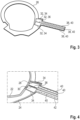
- a film forms the substrate 26 and to form the hearing aid 2, this film, together with the already applied conductor tracks, is preferably slipped over the E-units 10, placed on the base plate 6 of the housing 4 and glued to the base plate 6. This situation is in Fig.5 indicated by a schematic drawing. The E-units 10 then penetrate a central opening in the substrate 26.
- the previously mentioned free arm 24 encompasses in the embodiment according to Fig. 2 the auxiliary element 22 at least partially and is connected at one end to the auxiliary element 22 via a short-circuit arm 28. Distant from the short-circuit arm 28 branches off in the embodiment according to Fig. 2 In addition, a feed arm 30 extends from the free arm 24, via which the antenna unit 20 is also connected to the auxiliary element 22.
- the transmitting and receiving unit 18 also has a coupling element 32.
- the coupling element 32 is also formed by conductor tracks in the exemplary embodiment and these conductor tracks are applied to the same substrate 26 as the antenna unit 20 in this embodiment variant, but on the second side of the substrate 26 opposite the first side. This second side is in Fig.3 shown in a first version.
- the coupling element 32 now forms two conductor loops 34 arranged next to one another.
- the two conductor loops 34 are, as can be seen from Fig.3 can be seen, are connected to one another via a common feeder 36, to which the two conductor loops 34 are connected.
- the coupling element 32 is further arranged in the embodiment relative to the antenna unit 20 such that the feeder 36 is arranged in good approximation parallel to the feed arm 30 and the conductor loops 34 are symmetrical to the feed arm 30.
- This relative arrangement is in Fig.4 shown, whereby in this illustration only the conductor tracks are shown and the substrate 26 is hidden.
- connection element 38 is designed as a coplanar waveguide which has three conductor strips 40.
- the three conductor strips 40 are arranged parallel to one another and coplanar, and the two outer conductor strips 40 are each connected to one of the conductor loops 34.
- the middle conductor strip 40 is additionally connected to the feeder 36 and a signal is fed in or read out via this when the transmitting and receiving unit 18 is in operation.
- the conductor strips 40 are preferably supplemented by a conductor surface 42, which is applied in particular to the first side of the substrate 30 and which, like the two outer conductor strips 40, is subjected to a ground potential or reference potential during operation of the transmitting and receiving unit 18.
- This ground potential or reference potential is provided by the electronic circuit 16 of the transmitting and receiving unit 18 and supplied via a galvanic connection.
- the auxiliary element 22 is preferably also subjected to a ground potential or reference potential, although in the exemplary embodiment this is provided via a galvanic connection to the battery 12.
- the auxiliary element 22 and the coupling element 32 are galvanically separated from one another.
- FIG.6 A second embodiment of the coupling element 32 is shown. This differs from the embodiment according to Fig.3 above all by the fact that an auxiliary module 44 is integrated into the common supply conductor 36 and into each of the two conductor loops 34.
- the structure is preferably designed symmetrically and the three auxiliary modules 44 are in particular identical auxiliary modules 44.
- an auxiliary component 44 within the meaning of this application is typically an electrical component with an ohmic resistance, with a capacitance and/or with an inductance, for example a capacitor, a coil, a resistor or simply a conductor interruption, i.e. a gap.
- a third embodiment of the coupling element 32 is shown in Fig.7
- the coupling element 32 has only one conductor loop 46 instead of the previously described two conductor loops 34.
- FIG. 8 A second variant according to Fig.8 differs from the execution according to Fig.2 by the design of the free arm 24 on the one hand and the design of the auxiliary element 22 on the other hand.
- the auxiliary element 22 has Fig.8 no ring shape or at least no closed ring shape, rather the auxiliary element 22 is formed by an arc-shaped conductor with a free end.
- the arc-shaped conductor spans a Arc area or angle area of more than 180° and therefore in turn forms a conductor loop or conductor loop.
- the free end of the auxiliary element 22 and the free end of the free arm 24 are also designed as free ends with an end-side widening 48, so the corresponding free ends each end with a widening 48.
- width is to be understood in particular as meaning that the transverse extension of the free end in the region of the widening corresponds to at least 1.2 times, preferably at least 1.5 times and more preferably at least 2 times the transverse extension of the free arm away from the widening or before the start of the widening.
- a third variant according to Fig.9 differs from the execution according to Fig.8 in that the short-circuit arm 28 is not present.
- the free arm 24 and the auxiliary element 22 are only connected to one another via the feed arm 30.
- the feed arm 30, together with the adjoining conductor structure of the free arm 24 and the auxiliary element 22, forms a Z-shaped conductor structure or a Z-shaped course of the conductor tracks forming the antenna unit 20.
- FIG.10 A fourth variant is outlined. This differs from the version according to Fig.2 by an auxiliary module 50 of the aforementioned type, which connects the free arm 24 with the auxiliary element 22.
- the antenna unit 20 branches off according to Fig.10 an additional arm 52 extends from the free arm 24, specifically at a distance from the two ends of the free arm 24.
- This additional arm 52 preferably points away from the auxiliary element 22 and also preferably has a free end with an end-side widening 48 of the previously mentioned type.
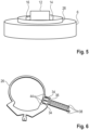
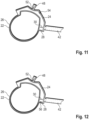
- the further design variants of the antenna unit 20 according to Fig. 11 to Fig. 14 differ from the version according to Fig.10 by the position and, if applicable, the design of the auxiliary modules 54 to 60, whereby each auxiliary module 54 to 60 is designed as an auxiliary module of the type mentioned above.
- the auxiliary modules 54 to 60 are therefore particularly designed as electrical modules of the designed in the manner described above, but depending on the application, possibly as different electrical components.
- the design variant of the antenna unit 20 according to Fig. 15 represents a modification or further development of the antenna unit 20 according to Fig.9
- the free arm 24 is designed as an extended free arm 24 and has a conductor extension 62 made of an electrically conductive material, through which, for example, a branch or ramification is formed.
- the conductor extension 62 By means of the conductor extension 62, the free arm 24 is formed starting from the design of the free arm 24 according to Fig.9 preferably capacitively loaded and in this way a resonance condition for the antenna unit 20 is typically specified.
- the conductor extension 62 in the exemplary embodiment is not formed by conductor tracks and is also not located in the previously mentioned plane, which is defined by a surface of the substrate 26. Instead, the conductor extension 62 is guided out of this plane or tilted out.
- the conductor extension 62 in the exemplary embodiment is formed, among other things, by a connecting arm that protrudes from the substrate 26 and is connected to a conductor track end or a widened conductor track end of a conductor track on the substrate.
- the corresponding conductor track forms the free arm 24 in the design of the antenna unit 20 according to Fig. 15 It corresponds to the design of the conductor track, which in the design of the antenna unit 20 according to Fig.9 the free arm 24 alone.
- the connecting arm is connected to Fig. 15 a transverse conductor which forms a T-shape together with the connecting arm.
- the transverse conductor is in turn connected to a U-shaped conductor element at both ends, with the opening of the U-shape preferably facing the substrate 26.
- a previously described ladder extension 62 is not part of the free arm 24 but part of the previously described additional arm 52 or is connected to the previously described additional arm 52.
Landscapes
- Engineering & Computer Science (AREA)
- Physics & Mathematics (AREA)
- Acoustics & Sound (AREA)
- Signal Processing (AREA)
- Health & Medical Sciences (AREA)
- General Health & Medical Sciences (AREA)
- Neurosurgery (AREA)
- Otolaryngology (AREA)
- Computer Networks & Wireless Communication (AREA)
- Manufacturing & Machinery (AREA)
- Details Of Aerials (AREA)
Applications Claiming Priority (1)
| Application Number | Priority Date | Filing Date | Title |
|---|---|---|---|
| DE102020201479.5A DE102020201479A1 (de) | 2020-02-06 | 2020-02-06 | Hörgerät |
Publications (2)
| Publication Number | Publication Date |
|---|---|
| EP3863304A1 EP3863304A1 (de) | 2021-08-11 |
| EP3863304B1 true EP3863304B1 (de) | 2024-04-24 |
Family
ID=73654644
Family Applications (1)
| Application Number | Title | Priority Date | Filing Date |
|---|---|---|---|
| EP20210861.9A Active EP3863304B1 (de) | 2020-02-06 | 2020-12-01 | Hörgerät mit induktiv gekoppelter antenneneinheit |
Country Status (4)
| Country | Link |
|---|---|
| US (1) | US11490215B2 (zh) |
| EP (1) | EP3863304B1 (zh) |
| CN (1) | CN113225656B (zh) |
| DE (1) | DE102020201479A1 (zh) |
Family Cites Families (31)
| Publication number | Priority date | Publication date | Assignee | Title |
|---|---|---|---|---|
| JP2001023807A (ja) | 1999-07-09 | 2001-01-26 | Toshiba Corp | 避雷器およびその製造方法 |
| DK1719384T3 (da) | 2004-02-19 | 2011-07-11 | Oticon As | Høreapparat med antenne til modtagelse og transmission af elektromagnetiske signaler og afskærmende batteri |
| US7652628B2 (en) * | 2008-03-13 | 2010-01-26 | Sony Ericsson Mobile Communications Ab | Antenna for use in earphone and earphone with integrated antenna |
| US8494197B2 (en) * | 2008-12-19 | 2013-07-23 | Starkey Laboratories, Inc. | Antennas for custom fit hearing assistance devices |
| EP2444982A1 (en) | 2010-10-22 | 2012-04-25 | ABB Research Ltd. | Shed for an electrical insulator and insulator with a plurality of such sheds |
| CN102856631B (zh) * | 2011-06-28 | 2015-04-22 | 财团法人工业技术研究院 | 天线与其通信装置 |
| US8761699B2 (en) * | 2011-12-28 | 2014-06-24 | Freescale Semiconductor, Inc. | Extendable-arm antennas, and modules and systems in which they are incorporated |
| US20130343586A1 (en) * | 2012-06-25 | 2013-12-26 | Gn Resound A/S | Hearing aid having a slot antenna |
| DK201270410A (en) * | 2012-07-06 | 2014-01-07 | Gn Resound As | BTE hearing aid with an antenna partition plane |
| US9980062B2 (en) * | 2012-12-12 | 2018-05-22 | Sivantos Pte. Ltd. | Hearing aid and method for producing a hearing aid |
| DK2932560T4 (da) * | 2012-12-12 | 2020-12-14 | Sivantos Pte Ltd | Foldet dipol til hørehjælpeapparat |
| US9641944B2 (en) * | 2013-08-16 | 2017-05-02 | Starkey Laboratories, Inc. | Method of tuning capacitance for hearing assistance device flex antenna |
| US9686621B2 (en) * | 2013-11-11 | 2017-06-20 | Gn Hearing A/S | Hearing aid with an antenna |
| US10595138B2 (en) * | 2014-08-15 | 2020-03-17 | Gn Hearing A/S | Hearing aid with an antenna |
| DE102014222451A1 (de) | 2014-09-30 | 2016-03-31 | Siemens Aktiengesellschaft | Gussverfahren zur Herstellung einer Schutzummantelung um ein Aktivteil eines Überspannungsableiters |
| US10440483B2 (en) * | 2015-11-25 | 2019-10-08 | Gn Hearing A/S | Hearing aid with improved wireless communication |
| US10477329B2 (en) * | 2016-10-27 | 2019-11-12 | Starkey Laboratories, Inc. | Antenna structure for hearing devices |
| EP3451701A1 (en) * | 2017-08-30 | 2019-03-06 | GN Hearing A/S | Hearing aid with an antenna |
| US10944156B2 (en) * | 2017-09-29 | 2021-03-09 | Apple Inc. | Wireless earphone antennas |
| EP3531718B1 (en) * | 2018-02-21 | 2022-01-19 | Oticon A/s | Hearing aid device having an antenna |
| WO2020001732A1 (en) | 2018-06-25 | 2020-01-02 | Sonova Ag | Transmission system for a body-worn electronic device |
| EP3629600A1 (en) * | 2018-09-28 | 2020-04-01 | GN Hearing A/S | Hearing device with antenna extending from the hearing device |
| JP7366049B2 (ja) * | 2018-10-15 | 2023-10-20 | ソニーセミコンダクタソリューションズ株式会社 | アンテナ装置、イヤホン |
| US10931005B2 (en) * | 2018-10-29 | 2021-02-23 | Starkey Laboratories, Inc. | Hearing device incorporating a primary antenna in conjunction with a chip antenna |
| EP3900109A1 (en) * | 2018-12-21 | 2021-10-27 | Starkey Laboratories, Inc. | Ear-worn devices with high-dielectric structural elements |
| US11355834B2 (en) * | 2019-02-06 | 2022-06-07 | Starkey Laboratories, Inc. | Ear-worn electronic device incorporating an antenna substrate comprising a dielectric gel or liquid |
| US11140496B2 (en) * | 2019-02-26 | 2021-10-05 | Starkey Laboratories, Inc. | Ear-worn electronic device incorporating an integrated battery/antenna module |
| US11122376B2 (en) * | 2019-04-01 | 2021-09-14 | Starkey Laboratories, Inc. | Ear-worn electronic device incorporating magnetically coupled feed for an antenna |
| US20200404434A1 (en) * | 2019-06-19 | 2020-12-24 | Starkey Laboratories, Inc. | Ear-worn electronic device incorporating antenna matching network comprising a non-foster circuit |
| WO2021097783A1 (en) * | 2019-11-22 | 2021-05-27 | Goertek Technology Co., Ltd. | Antenna and wireless earbud comprising the same |
| EP3890354A1 (en) * | 2020-03-30 | 2021-10-06 | GN Hearing A/S | Hearing device with printed circuit board assembly and output transducer |
-
2020
- 2020-02-06 DE DE102020201479.5A patent/DE102020201479A1/de active Pending
- 2020-12-01 EP EP20210861.9A patent/EP3863304B1/de active Active
-
2021
- 2021-02-03 CN CN202110148532.XA patent/CN113225656B/zh active Active
- 2021-02-08 US US17/169,749 patent/US11490215B2/en active Active
Also Published As
| Publication number | Publication date |
|---|---|
| DE102020201479A1 (de) | 2021-08-12 |
| US20210250710A1 (en) | 2021-08-12 |
| CN113225656A (zh) | 2021-08-06 |
| EP3863304A1 (de) | 2021-08-11 |
| CN113225656B (zh) | 2022-12-13 |
| US11490215B2 (en) | 2022-11-01 |
Similar Documents
| Publication | Publication Date | Title |
|---|---|---|
| EP3427339B1 (de) | Antenne | |
| EP2932560B2 (de) | Faltdipol für hörhilfegeräte | |
| EP2811761B1 (de) | Antenneneinrichtung für Hörinstrumente | |
| EP3413587B1 (de) | Hörgerät, insbesondere hinter-dem-ohr-hörhilfegerät | |
| EP1389891B1 (de) | Platzsparende Antennenanordnung für Hörhilfegeräte | |
| DE602005002886T2 (de) | Kopfhörerantenne | |
| EP2782363B1 (de) | Binaurales Hörinstrument sowie Ohrstück | |
| EP3322032B1 (de) | Hörhilfegerät mit elektronikrahmen und darin integrierter antenne | |
| EP2894880A2 (de) | Antenneneinrichtung für Hörinstrumente | |
| EP3567672B1 (de) | Hörhilfegerät mit elektronikrahmen und darin integrierter antenne | |
| DE102016207844A1 (de) | Hörgerät | |
| EP3826327B1 (de) | Hörgerät | |
| EP3836565B1 (de) | Leiterplatte eines hörgeräts | |
| EP2034770A2 (de) | Übertragungseinrichtung für eine Hörvorrichtung mit Folienleiterschirmung und eigengeschirmte Spule | |
| EP1959712A2 (de) | Hörvorrichtung mit Hörerkompensationsspule | |
| EP3863304B1 (de) | Hörgerät mit induktiv gekoppelter antenneneinheit | |
| EP3863305A1 (de) | Hörgerät | |
| DE102017012195B4 (de) | Hörgerät, insbesondere Hinter-dem-Ohr-Hörhilfegerät | |
| DE102008054087A1 (de) | Hörhilfegerät mit mindestens einem kapazitiven Näherungssensor | |
| EP2911312B1 (de) | Antenne mit Schirmvorrichtung und Herstellungsverfahren | |
| DE102021200195B4 (de) | Hörgerät | |
| DE102020209124A1 (de) | ITE-Hörgerät | |
| EP1915030B1 (de) | Hörgerät mit stromführendem Metallbügel | |
| EP4054208A1 (de) | Hörgerät, antenne für ein hörgerät und verfahren zur herstellung eines hörgeräts | |
| EP4284024A1 (de) | Hörgerät mit einer multifeed-antennenvorrichtung |
Legal Events
| Date | Code | Title | Description |
|---|---|---|---|
| PUAI | Public reference made under article 153(3) epc to a published international application that has entered the european phase |
Free format text: ORIGINAL CODE: 0009012 |
|
| STAA | Information on the status of an ep patent application or granted ep patent |
Free format text: STATUS: THE APPLICATION HAS BEEN PUBLISHED |
|
| AK | Designated contracting states |
Kind code of ref document: A1 Designated state(s): AL AT BE BG CH CY CZ DE DK EE ES FI FR GB GR HR HU IE IS IT LI LT LU LV MC MK MT NL NO PL PT RO RS SE SI SK SM TR |
|
| STAA | Information on the status of an ep patent application or granted ep patent |
Free format text: STATUS: REQUEST FOR EXAMINATION WAS MADE |
|
| 17P | Request for examination filed |
Effective date: 20220210 |
|
| RBV | Designated contracting states (corrected) |
Designated state(s): AL AT BE BG CH CY CZ DE DK EE ES FI FR GB GR HR HU IE IS IT LI LT LU LV MC MK MT NL NO PL PT RO RS SE SI SK SM TR |
|
| GRAP | Despatch of communication of intention to grant a patent |
Free format text: ORIGINAL CODE: EPIDOSNIGR1 |
|
| STAA | Information on the status of an ep patent application or granted ep patent |
Free format text: STATUS: GRANT OF PATENT IS INTENDED |
|
| INTG | Intention to grant announced |
Effective date: 20240103 |
|
| GRAS | Grant fee paid |
Free format text: ORIGINAL CODE: EPIDOSNIGR3 |
|
| GRAA | (expected) grant |
Free format text: ORIGINAL CODE: 0009210 |
|
| STAA | Information on the status of an ep patent application or granted ep patent |
Free format text: STATUS: THE PATENT HAS BEEN GRANTED |
|
| AK | Designated contracting states |
Kind code of ref document: B1 Designated state(s): AL AT BE BG CH CY CZ DE DK EE ES FI FR GB GR HR HU IE IS IT LI LT LU LV MC MK MT NL NO PL PT RO RS SE SI SK SM TR |
|
| REG | Reference to a national code |
Ref country code: GB Ref legal event code: FG4D Free format text: NOT ENGLISH |
|
| REG | Reference to a national code |
Ref country code: CH Ref legal event code: EP |
|
| REG | Reference to a national code |
Ref country code: DE Ref legal event code: R096 Ref document number: 502020007743 Country of ref document: DE |
|
| REG | Reference to a national code |
Ref country code: IE Ref legal event code: FG4D Free format text: LANGUAGE OF EP DOCUMENT: GERMAN |