EP3862913B1 - Druckprüfvorrichtung - Google Patents
Druckprüfvorrichtung Download PDFInfo
- Publication number
- EP3862913B1 EP3862913B1 EP19869212.1A EP19869212A EP3862913B1 EP 3862913 B1 EP3862913 B1 EP 3862913B1 EP 19869212 A EP19869212 A EP 19869212A EP 3862913 B1 EP3862913 B1 EP 3862913B1
- Authority
- EP
- European Patent Office
- Prior art keywords
- value
- image
- printing
- dimensional code
- threshold value
- Prior art date
- Legal status (The legal status is an assumption and is not a legal conclusion. Google has not performed a legal analysis and makes no representation as to the accuracy of the status listed.)
- Active
Links
Images


Classifications
-
- G—PHYSICS
- G06—COMPUTING OR CALCULATING; COUNTING
- G06K—GRAPHICAL DATA READING; PRESENTATION OF DATA; RECORD CARRIERS; HANDLING RECORD CARRIERS
- G06K7/00—Methods or arrangements for sensing record carriers, e.g. for reading patterns
- G06K7/10—Methods or arrangements for sensing record carriers, e.g. for reading patterns by electromagnetic radiation, e.g. optical sensing; by corpuscular radiation
- G06K7/14—Methods or arrangements for sensing record carriers, e.g. for reading patterns by electromagnetic radiation, e.g. optical sensing; by corpuscular radiation using light without selection of wavelength, e.g. sensing reflected white light
- G06K7/1404—Methods for optical code recognition
- G06K7/1408—Methods for optical code recognition the method being specifically adapted for the type of code
- G06K7/1417—2D bar codes
-
- G—PHYSICS
- G06—COMPUTING OR CALCULATING; COUNTING
- G06K—GRAPHICAL DATA READING; PRESENTATION OF DATA; RECORD CARRIERS; HANDLING RECORD CARRIERS
- G06K5/00—Methods or arrangements for verifying the correctness of markings on a record carrier; Column detection devices
- G06K5/02—Methods or arrangements for verifying the correctness of markings on a record carrier; Column detection devices the verifying forming a part of the marking action
-
- G—PHYSICS
- G06—COMPUTING OR CALCULATING; COUNTING
- G06K—GRAPHICAL DATA READING; PRESENTATION OF DATA; RECORD CARRIERS; HANDLING RECORD CARRIERS
- G06K7/00—Methods or arrangements for sensing record carriers, e.g. for reading patterns
- G06K7/10—Methods or arrangements for sensing record carriers, e.g. for reading patterns by electromagnetic radiation, e.g. optical sensing; by corpuscular radiation
- G06K7/14—Methods or arrangements for sensing record carriers, e.g. for reading patterns by electromagnetic radiation, e.g. optical sensing; by corpuscular radiation using light without selection of wavelength, e.g. sensing reflected white light
- G06K7/1404—Methods for optical code recognition
- G06K7/1439—Methods for optical code recognition including a method step for retrieval of the optical code
-
- G—PHYSICS
- G06—COMPUTING OR CALCULATING; COUNTING
- G06T—IMAGE DATA PROCESSING OR GENERATION, IN GENERAL
- G06T7/00—Image analysis
- G06T7/0002—Inspection of images, e.g. flaw detection
- G06T7/0004—Industrial image inspection
-
- G—PHYSICS
- G06—COMPUTING OR CALCULATING; COUNTING
- G06T—IMAGE DATA PROCESSING OR GENERATION, IN GENERAL
- G06T7/00—Image analysis
- G06T7/10—Segmentation; Edge detection
- G06T7/11—Region-based segmentation
-
- G—PHYSICS
- G06—COMPUTING OR CALCULATING; COUNTING
- G06T—IMAGE DATA PROCESSING OR GENERATION, IN GENERAL
- G06T7/00—Image analysis
- G06T7/10—Segmentation; Edge detection
- G06T7/136—Segmentation; Edge detection involving thresholding
-
- G—PHYSICS
- G06—COMPUTING OR CALCULATING; COUNTING
- G06T—IMAGE DATA PROCESSING OR GENERATION, IN GENERAL
- G06T2207/00—Indexing scheme for image analysis or image enhancement
- G06T2207/30—Subject of image; Context of image processing
- G06T2207/30108—Industrial image inspection
- G06T2207/30144—Printing quality
Definitions
- the present invention relates to a printing inspection device and particularly relates to a printing inspection device suitable for reading a two-dimensional code (simply referred to as a "character” below because a symbol or the two-dimensional code is included in a character) with a camera and determining the quality of printing, the two-dimensional code in which, for example, characters and symbols such as the production date or a serial number printed by an inkjet printer and the like and information necessary for production history management are recorded.
- a two-dimensional code (simply referred to as a "character” below because a symbol or the two-dimensional code is included in a character) with a camera and determining the quality of printing
- the two-dimensional code in which, for example, characters and symbols such as the production date or a serial number printed by an inkjet printer and the like and information necessary for production history management are recorded.
- JP 2009-70061 A discloses that "in a case where decoding of a two-dimensional code fails, when cells forming one pattern among black and white patterns forming a specific pattern completely coincide with cells forming a predetermined pattern, and the coincidence degree of another pattern is out of a predetermined range, a binarization parameter is adjusted to cause the coincidence degree to enter into the predetermined range, and binarization is performed again to decode a binary image".
- US 9 135 489 B2 relates to a system for decoding a two dimensional code and method therefore, wherein in a binarization process of a two dimensional code image, through performing a dividing operation on the two dimensional code image, each block region has a different grayscale threshold.
- US 9 230 148 B2 relates to a binarization method and system for two dimensional code images, wherein each block region has a different grayscale threshold.
- each block region has a different grayscale threshold.
- whether a pixel in the block region is determined as black or white restoring process is not solely based on the grayscale value of the pixel itself, but also an average grayscale value of a predetermined area specified for a block region where the pixel locates.
- JP 2011 233099 A relates to an optical information reader and an optical information reading method, wherein a code scanner is configured to acquire image data of respective pixels in pixel strings in parallel with a line of modules from a part corresponding to the one same line of the modules constituting the code to be read in images concerning the respective images photographed at three or more timings.
- a printing device such as an ink jet printer is used to realize the labeling.
- the printing device is installed on a transport line (including a packing line) and performs printing on a packing container which is transported one after another.
- a printing inspection device that reads printing of the packing container determines whether or not printing by the printing device is correctly performed.
- Patent Document 1 focuses only on the ratio of white and black.
- the position of a cell after binarization is determined to be largely shifted by the degree of position shift of the cell to the pixel, and thus it may not be possible to read the two-dimensional code.
- an object of the present invention is to obtain a printing inspection device that obtains an optimum binarization threshold value in the printing inspection device that captures an image including a two-dimensional code printed by a general-purpose printer such as an ink jet printer, as a multi-level image, creates a binary image from the multi-level image with a predetermined binarization threshold value, and then performs decoding.
- a printing inspection device reads printing including a two-dimensional code printed on a printing target.
- the printing inspection device includes means for inputting a recognition target including a two-dimensional code in a form of a multi-level image, image binarization means for binarizing the multi-level image with a predetermined binarization threshold value and outputting a binary image, two-dimensional code detection means for detecting a region of a two-dimensional code from the binary image, decoding means for decoding the two-dimensional code, and read test means for performing a read test.
- the read test means performs a read test by binarizing one or more inspection samples with brightness values for all gradations, as a threshold value, obtains a maximum value and a minimum value of readable brightness values, causes the obtained maximum value and minimum value to be displayed in a display portion, and sets a median value between the minimum value and the maximum value, as a binarization threshold value for a two-dimensional code image in a practical printing inspection.
- a printing inspection device capable of obtaining an optimum binarization threshold value when a binary image is created from a multi-level image with a predetermined binarization threshold value, and then decoding is performed.
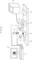
- Fig. 2 illustrates an installation example of a printing inspection device used in the present example.
- the printing inspection device includes a lighting device 4, a camera 3, a monitor 2, a printing inspection-device body 1, an external device, and the like.
- the lighting device 4 irradiates a printed matter 6 with light having a light quantity sufficient to cause the camera 3 to read a printed character.
- the printed matter 6 is obtained in a manner that a printing device such as an ink jet printer 9 performs printing on a packing container for foods and chemicals.
- the camera 3 refers to image capturing means for reading an image including a character string, a two-dimensional code, or the like, which serves as an inspection target in the printed matter 6 with which the light is irradiated.
- the monitor 2 displays the read image or displays condition settings of an inspection and an inspection result.
- a processing unit and a lighting control unit are mounted in the printing inspection-device body 1.
- the processing unit performs processing, for example, extracting a print image from an image read from the camera 3 and performs acceptance determination of an inspection target character.
- the lighting control unit controls the light quantity, the timing, and the like of lighting.
- the external device transmits various instructions of image processing and the like to the processing unit in the printing inspection-device body 1.
- droplets 11 are discharged onto the surface of a bottle or a can being a product before shipment, by a print head 10 of a dedicated ink jet printer 9 to perform printing of the expiration date, the serial number, a two-dimensional code, and the like.
- a product 6 before shipment, on which printing is performed by the ink jet printer 9, is transported by a conveyor 5 or the like.
- the processing unit in the printing inspection-device body 1 detects an output signal from a sensor 8 installed in the vicinity of the conveyor, and calculates an image capturing timing of the camera 3.
- the lighting device 4 such as an LED lighting performs irradiation with light, and the camera 3 reads an image including the inspection target character. Then, a print image is transmitted into the printing inspection-device body 1.
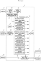
- Fig. 3 is a block diagram illustrating an example of the printing inspection device in the present example.
- a program for recognition processing of a printing character string, a two-dimensional code, or the like or a program for acceptance determination of printing quality is stored in a ROM 13.
- a reference character pattern of constituent characters of a character string as an inspection target, setting data input from the external device 7, and the like are stored in a RAM 13.
- the processing unit 12 performs various types of processing related to the printing inspection.
- a read test is performed using a test inspection sample in order to determine a binarization threshold value.
- an image capturing timing calculation unit 121 in the processing unit 12 calculates an image capturing timing of the camera.
- An image input signal generation unit 17 notifies the camera 3 of an image capturing timing in response to an instruction from the processing unit 12.
- the lighting control unit 19 controls the light quantity of the lighting device 4 and controls an emission timing of the lighting device 4 in accordance with an image reading timing of the camera 3.
- the image read by the camera 3 is multi-level image data in which each pixel has a numerical value (referred to as a "brightness value” below) depending on the brightness among the number of gradations determined by the performance of the camera.
- the data is input to an image input unit 15 in the printing inspection-device body 1, and stored once in an image storage unit 16.
- a filtering processing unit 122 in the processing unit 12 performs image improvement processing such as thinning and thickening on the captured image stored in the image storage unit 16, in order to easily recognize a two-dimensional code.
- a binarization threshold value setting unit 123 acquires an optimum binarization threshold value for the image subjected to filtering processing, in accordance with the procedure described later.
- An image capturing timing calculation unit 124 in the processing unit 12 calculates the image capturing timing of the camera.
- the camera 3 performs image capturing to obtain multi-level image data.
- a filtering processing unit 125 in the processing unit 12 performs image improvement processing on the multi-level image data.
- a binarization threshold value setting unit 126 sets the optimum binarization threshold value based on the binarization threshold value obtained in [read test step].
- An image binarization processing unit 127 performs binarization processing using the binarization threshold value obtained by the binarization threshold value setting unit 126, so as to create a binary image from the multi-level image.
- a two-dimensional code computation unit 128 detects a region of the two-dimensional code from the obtained binary image, reads data of the two-dimensional code, and decodes the two-dimensional code. Then, a reading determination unit 129 performs acceptance determination and transmits the determination result to an input and output unit 18. The determination result is displayed on the monitor 2. When the determination result means failure, the external device 7 rejects the product as a defective product. Further, in the above series of processing, the print image, an inspection condition, and the like are also transmitted to the input and output unit 18 and then are displayed on the monitor 2.
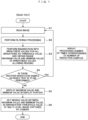
- Fig. 1 illustrates an example of a flowchart of processing after image capturing in the [read test step] of the processing unit 12 in the printing inspection device in the present example.
- the processing unit 12 in the printing inspection-device body 1 receives the output signal of the sensor 8, and then the image is read by the camera 3 at a predetermined timing.
- the read image is stored once in the image storage unit 16 in Step S1.
- Step S2 the filtering processing unit 122 in the processing unit 12 performs image improvement processing.
- Steps S3 to S6 represent processing of the binarization threshold value setting unit 123 in the processing unit 12.
- Step S3 regarding an image after filtering processing, binarization is performed with the brightness values for all gradations as a threshold value, and it is checked whether or not a two-dimensional code is read. For example, in a case of an image having 256 gradations, it is checked whether or not a two-dimensional code can be read, for all binarization threshold values of 0 to 255.
- the minimum brightness threshold value allowing a two-dimensional code to be read is set as MIN1, and the maximum brightness threshold value is set as MAX1.
- Step S4 it is determined whether there is another inspection sample on which the read test is to be performed. Regarding the number of inspection samples, one piece is possible, and two or more pieces are desirable to improve accuracy against variation.
- processing from Step S1 is also performed on the second and the subsequent inspection samples.
- the minimum brightness threshold values MIN2, MIN3, ... and the maximum brightness threshold values MAX2, MAX3, ... which are obtained by performing the processing up to Step S3 are obtained.
- the minimum brightness threshold values and the maximum brightness threshold values corresponding to the number of inspection samples are obtained.
- the average values are obtained from the brightness threshold values and set as the minimum brightness value MIN and the maximum brightness value MAX.
- Step S5 the minimum brightness value MIN and the maximum brightness value MAX are transmitted to the input and output unit 18 and displayed on the monitor 2.
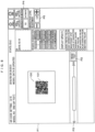
- Fig. 4 illustrates a display example.
- a two-dimensional code-image display portion P1 represents an image capturing region of the camera 3.
- a white region 100 including a two-dimensional code image at the center is a reading region.
- the reading region is set on an inspection condition setting screen (not illustrated).
- the captured image is located out of this region, the product is considered as a printed matter having a printing position deviation which is larger than an allowable range, and thus is determined as a defective product.
- As an example of a two-dimensional code image 101 at the center of the region 100 an image of a QR code (registered trademark) is displayed.
- QR code registered trademark
- Step S3 When a "read test” button is pressed, Step S3 is performed. The result is displayed on the left of the "read test” button. "0" indicates the minimum value of the binarization threshold value for performing the read test, and "255" indicates the maximum value of the binarization threshold value for performing the read test. A rectangle between the numerical values indicates the range of the binarization threshold value allowing a two-dimensional code to be read. Fig. 4 illustrates that a two-dimensional code can be read in a range of the binarization threshold value from "51" to "198".
- Step S6 the median value is obtained from the minimum value MIN and the maximum value MAX of the binarization threshold values allowing a two-dimensional code to be read, and is set as the binarization threshold value when the printing inspection is performed.
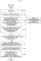
- Fig. 5 illustrates an example of a flowchart of processing after image capturing in the "printing inspection step" of the processing unit 12 according to the printing inspection device of the present example.
- the processing unit 12 in the printing inspection-device body 1 receives the output signal of the sensor 8, and then the camera 3 reads an image at a predetermined timing.
- Step S11 the read image is stored once in the image storage unit 16.
- Step S12 the filtering processing unit 125 in the processing unit 12 performs image improvement processing.
- Step S13 the binarization threshold value setting unit 126 sets the median value obtained in the "read test" as the binarization threshold value.
- Step S14 the image binarization processing unit 127 creates a binary image from a multi-level image with the binarization threshold value set in Step S13.
- the two-dimensional code computation unit 128 performs Steps S15 to S19.
- Step S15 investigation of a finder (pattern for position detection) is performed based on the binary image.
- Step S17 information (Version and the like) necessary for acquiring data is read based on the position of the finder.
- Step S18 data is taken based on information obtained in Step S17.
- Step S19 data (coded data) acquired in Step S18 is decoded to restore original data.
- the reading determination unit 129 performs acceptance determination on the read data.
- the processing unit 12 performs the [printing inspection step], not the [read test step]. Similar to Fig. 5 , an image is captured in Step S11, and filtering processing is performed in Step S12. Then, in Step S14, a binary image is created from a multi-level image by using the binarization threshold value set as the default value in Step S13. In Step S15, the finder investigation is performed based on the binary image. In Step S16, it is determined whether or not the finder inspection is possible. When finder investigation is possible, the multiplication multiplier for determining the binarization threshold value is changed in Step S21. In Step S13, re-setting of the binarization threshold value, image binarization, and finder investigation are performed using the changed multiplication multiplier. Steps S21, S13, S14, S15, and S16 are repeated until the finder inspection is possible.
- all gradation values are used as the binarization threshold value by the [read test], the binarization of a multi-level image is performed to check whether or not reading of a two-dimensional code is possible, and the optimum binarization threshold value is set in advance.
- the binarization threshold value is set in advance.
- the printing inspection device in the present example captures an image including a two-dimensional code printed by a general-purpose printer such as an ink jet printer, in a form of a multi-level image.
- the printing inspection device creates a binary image from the multi-level image with a predetermined binarization threshold value, and then performs decoding. According to the printing inspection device, it is possible to obtain the optimum binarization threshold value without an occurrence of a situation in which the processing time becomes long by repeating binarization or a product is determined as a defective product because the code is not read within a desired time.
- Fig. 7 illustrates an example of a flowchart of processing after image capturing in the [read test step] of the processing unit 12 in the printing inspection device in the present example. Similar to the case in Fig. 1 , an image is captured in Step S1, filtering processing is performed in Step S2, and the minimum value MIN1 and the maximum value MAX1 of brightness values allowing reading are obtained in Step S3.
- an average brightness value AVE1 for all pixels in a two-dimensional code reading region is calculated in Step S31. Similar to the case in Fig. 1 , regarding the number of inspection samples, one piece is possible, and two or more pieces are desirable to improve accuracy against variation. When two or more inspection samples are provided, processing from Step S1 is also performed on the second and the subsequent inspection samples.
- the minimum brightness threshold values MIN2, MIN3, ..., the maximum brightness threshold values MAX2, MAX3, ..., and all-pixel average brightness values AVE2, AVE3, ... in the reading region, which are obtained by performing processing up to Step S31 are obtained.
- the minimum brightness threshold values, the maximum brightness threshold values, and the all-pixel average brightness values in the reading region which correspond to the number of inspection samples, are obtained.
- the average values are obtained from the obtained brightness threshold values and set as the minimum brightness value MIN, the maximum brightness value MAX, and the all-pixel average brightness value AVE in the reading region, respectively.
- Step S5 the minimum brightness value MIN, the maximum brightness value MAX, and the all-pixel average brightness value AVE in the reading region are transmitted to the input and output unit 18 and are displayed on the monitor 2.
- Step S6 the median value between the maximum value and the minimum value is obtained.
- Fig. 8 illustrates a display example. In the present example, a button for the binarization method selects "automatic” P4. As the result of the read test, which is displayed on the left of the "read test” button, similar to the case in Fig.
- Step S9 an image is captured in Step S11, and filtering processing is performed in Step S12. Then, the average brightness value for all pixels in the reading region is calculated in Step S33.
- Step S34 a numerical value obtained by adding the correction value obtained in the [read test step] to the average brightness value for all pixels in the reading region is set as the binarization threshold value.
- Step S14 a binary image is created from a multi-level image by using the binarization threshold value.
- the average brightness value for all pixels in the reading region is calculated, the numerical value obtained by adding the correction value to the average value is set as the binarization threshold value, and binarization of a multi-level image is performed with the binarization threshold value.
- the average values of the obtained numerical values are set as MIN and the maximum binarization threshold value MAX, respectively.
- a method of setting the maximum value of the minimum binarization threshold values MIN1, MIN2, ... as MIN and setting the minimum value of the maximum binarization threshold values MAX1, MAX2, ... as MAX is also effective.
- the processing unit performing the [read test step] and the processing unit performing the [printing inspection step] are set to be separate from each other.
- the processing units (for example, image capturing timing calculation units 121 and 124) that perform the same operation can be set as the same processing unit.
Landscapes
- Engineering & Computer Science (AREA)
- Physics & Mathematics (AREA)
- Theoretical Computer Science (AREA)
- General Physics & Mathematics (AREA)
- Computer Vision & Pattern Recognition (AREA)
- Health & Medical Sciences (AREA)
- Quality & Reliability (AREA)
- Electromagnetism (AREA)
- General Health & Medical Sciences (AREA)
- Toxicology (AREA)
- Artificial Intelligence (AREA)
- Image Processing (AREA)
- Investigating Materials By The Use Of Optical Means Adapted For Particular Applications (AREA)
- Image Analysis (AREA)
- Accessory Devices And Overall Control Thereof (AREA)
Claims (1)
- Druckinspektionsvorrichtung, die Druck liest, der einen zweidimensionalen Code enthält, der auf ein Druckziel gedruckt ist, wobei die Vorrichtung Folgendes umfasst:Mittel zum Eingeben eines Erkennungsziels, das einen zweidimensionalen Code in Form eines Mehrebenenbildes enthält;Bildbinarisierungsmittel zum Binarisieren des Mehrebenenbildes mit einem vorbestimmten Binarisierungsschwellenwert und Ausgeben eines Binärbildes;Zweidimensionaler-Code-Detektionsmittel zum Detektieren eines Bereichs eines zweidimensionalen Codes aus dem Binärbild;Decodiermittel zum Decodieren des zweidimensionalen Codes; undLesetestmittel zum Durchführen eines Lesetests (P2),wobei die Lesetestmitteleinen Lesetest (P2) durch Binarisieren einer oder mehrerer Inspektionsproben mit Helligkeitswerten für alle Abstufungen als einen Schwellenwert durchführen undeinen Maximalwert und einen Minimalwert von auslesbaren Helligkeitswerten erhalten,dadurch gekennzeichnet, dassdie Lesetestmittelbewirken, dass der erhaltene Maximalwert und Minimalwert in einem Anzeigeabschnitt (P1) angezeigt werden, undeinen Medianwert zwischen dem Minimalwert und dem Maximalwert als einen Binarisierungsschwellenwert für ein zweidimensionales Codebild (101) in einer praktischen Druckinspektion einstellen,wobei, wenn der Lesetest (P2) durchgeführt wird,ein durchschnittlicher Helligkeitswert (AVE1) für alle Pixel in einem Drucklesebereich, undeine Differenz zwischen dem berechneten durchschnittlichen Helligkeitswert (AVE1) und dem Medianwert als ein Korrekturwert erhalten wird,in der praktischen Druckinspektion,der durchschnittliche Helligkeitswert (AVE1) für alle Pixel in dem Drucklesebereich für jedes Inspektionsziel berechnet wird, unddas Mehrebenenbild mit einem numerischen Wert, der durch Addieren des Korrekturwerts zu dem durchschnittlichen Helligkeitswert (AVE1) erhalten wird, als der Binarisierungsschwellenwert binarisiert wird.
Applications Claiming Priority (2)
| Application Number | Priority Date | Filing Date | Title |
|---|---|---|---|
| JP2018186328 | 2018-10-01 | ||
| PCT/JP2019/037463 WO2020071188A1 (ja) | 2018-10-01 | 2019-09-25 | 印字検査装置 |
Publications (3)
| Publication Number | Publication Date |
|---|---|
| EP3862913A1 EP3862913A1 (de) | 2021-08-11 |
| EP3862913A4 EP3862913A4 (de) | 2022-07-06 |
| EP3862913B1 true EP3862913B1 (de) | 2025-05-21 |
Family
ID=70055010
Family Applications (1)
| Application Number | Title | Priority Date | Filing Date |
|---|---|---|---|
| EP19869212.1A Active EP3862913B1 (de) | 2018-10-01 | 2019-09-25 | Druckprüfvorrichtung |
Country Status (5)
| Country | Link |
|---|---|
| US (1) | US11514256B2 (de) |
| EP (1) | EP3862913B1 (de) |
| JP (1) | JP7057433B6 (de) |
| CN (1) | CN112740218B (de) |
| WO (1) | WO2020071188A1 (de) |
Families Citing this family (2)
| Publication number | Priority date | Publication date | Assignee | Title |
|---|---|---|---|---|
| US20230161989A1 (en) * | 2021-11-23 | 2023-05-25 | VIRNECT inc. | Method and system for setting dynamic image threshold for two-dimensional identification code detection |
| JP2024145691A (ja) * | 2023-03-31 | 2024-10-15 | 株式会社キーエンス | 画像処理装置 |
Family Cites Families (22)
| Publication number | Priority date | Publication date | Assignee | Title |
|---|---|---|---|---|
| JP2004054529A (ja) * | 2002-07-18 | 2004-02-19 | Sharp Corp | 2次元コード読み取り方法,2次元コード読み取りプログラム,該2次元コード読み取りプログラムの記録媒体及び2次元コード読み取り装置 |
| JP2005165949A (ja) * | 2003-12-05 | 2005-06-23 | Toshiba Social Automation Systems Co Ltd | バーコード読み取り方法及びバーコード読み取り装置 |
| US7748810B2 (en) * | 2005-07-05 | 2010-07-06 | Seiko Epson Corporation | Image processing device, calibration table generator, image processing method, program product, and test pattern |
| JP4931703B2 (ja) * | 2007-06-20 | 2012-05-16 | 富士フイルム株式会社 | 液体吐出装置及びその清掃装置の検査方法 |
| JP4728297B2 (ja) * | 2007-07-30 | 2011-07-20 | 東芝テック株式会社 | 2次元コード読取装置及びその方法 |
| JP5145833B2 (ja) | 2007-09-12 | 2013-02-20 | 株式会社リコー | 2次元コード読み取り装置、2次元コード読み取り方法、2次元コード読み取りプログラム及び記録媒体 |
| JP5094504B2 (ja) * | 2008-03-28 | 2012-12-12 | 富士フイルム株式会社 | 画像形成装置 |
| JP5160488B2 (ja) * | 2009-03-23 | 2013-03-13 | 富士フイルム株式会社 | ドット位置測定方法及び装置並びにプログラム |
| JP5478268B2 (ja) * | 2010-01-13 | 2014-04-23 | 任天堂株式会社 | 画像処理プログラム、画像処理装置、画像処理方法および画像処理システム |
| JP2011233099A (ja) * | 2010-04-30 | 2011-11-17 | Optoelectronics Co Ltd | 光学的情報読取装置及び光学的情報読取方法 |
| WO2012011579A1 (ja) * | 2010-07-23 | 2012-01-26 | 独立行政法人産業技術総合研究所 | 病理組織画像の領域分割画像データ作成システム及び病理組織画像の特徴抽出システム |
| JP5555672B2 (ja) * | 2011-07-14 | 2014-07-23 | 東芝テック株式会社 | 画像処理装置 |
| CN104517089B (zh) | 2013-09-29 | 2017-09-26 | 北大方正集团有限公司 | 一种二维码解码系统及其方法 |
| CN104517110B (zh) * | 2013-09-29 | 2018-01-05 | 北大方正集团有限公司 | 一种二维码图像的二值化方法及系统 |
| CN107111771B (zh) * | 2015-01-13 | 2020-04-10 | At信息股份有限公司 | 二维码生成装置、二维码生成方法以及计算机能够读取的记录介质 |
| JP6675831B2 (ja) * | 2015-03-27 | 2020-04-08 | 株式会社日立産機システム | 印字検査方法及びそれを用いた印字検査装置及び印字検査装置本体 |
| JP5792409B1 (ja) * | 2015-04-07 | 2015-10-14 | 株式会社フューチャーアプリケーション | 光学的読取装置および光学的読取プログラム |
| JP2016218816A (ja) * | 2015-05-22 | 2016-12-22 | ローランドディー.ジー.株式会社 | 識別記号のマーキング品質評価装置および識別記号のマーキング品質評価方法 |
| JP2019006009A (ja) * | 2017-06-23 | 2019-01-17 | キヤノン株式会社 | 画像形成装置とその制御方法及びプログラム |
| JP7062991B2 (ja) * | 2018-02-13 | 2022-05-09 | コニカミノルタ株式会社 | 検出装置、インクジェット記録装置及び検出方法 |
| US10708406B2 (en) * | 2018-04-25 | 2020-07-07 | Future Dial, Inc. | Enhanced system and method for fully automated reverse logistics platform |
| US11205259B2 (en) * | 2019-01-28 | 2021-12-21 | Future Dial, Inc. | Enhanced automatic cosmetic grading |
-
2019
- 2019-09-25 EP EP19869212.1A patent/EP3862913B1/de active Active
- 2019-09-25 CN CN201980059461.7A patent/CN112740218B/zh active Active
- 2019-09-25 JP JP2020550321A patent/JP7057433B6/ja active Active
- 2019-09-25 US US17/281,787 patent/US11514256B2/en active Active
- 2019-09-25 WO PCT/JP2019/037463 patent/WO2020071188A1/ja not_active Ceased
Also Published As
| Publication number | Publication date |
|---|---|
| JP7057433B2 (ja) | 2022-04-19 |
| CN112740218A (zh) | 2021-04-30 |
| US11514256B2 (en) | 2022-11-29 |
| EP3862913A4 (de) | 2022-07-06 |
| WO2020071188A1 (ja) | 2020-04-09 |
| JP7057433B6 (ja) | 2022-05-16 |
| US20210383087A1 (en) | 2021-12-09 |
| JPWO2020071188A1 (ja) | 2021-09-02 |
| CN112740218B (zh) | 2023-08-25 |
| EP3862913A1 (de) | 2021-08-11 |
Similar Documents
| Publication | Publication Date | Title |
|---|---|---|
| US11270404B2 (en) | Digital watermarking applications | |
| US20250343866A1 (en) | Methods, apparatuses, and systems for detecting printing defects and contaminated components of a printer | |
| JP6869208B2 (ja) | 光電式コードリーダ及び光学コードの読み取り方法 | |
| US10061946B2 (en) | Method and apparatus for industrial identification mark verification | |
| EP3497708B1 (de) | Druckvorrichtung, druckermarkierungssystem und verfahren mit mehrstufiger produktionsdruckinspektion | |
| US20110150346A1 (en) | Method and Apparatus for Identifying Embossed Characters | |
| JP6250793B2 (ja) | カラー画像における文字背景除去方法及び装置 | |
| EP3862913B1 (de) | Druckprüfvorrichtung | |
| CN115302963A (zh) | 一种基于机器视觉的条形码印刷控制方法、系统及介质 | |
| JP7671944B2 (ja) | 品質検査装置 | |
| US11829837B2 (en) | Symbol evaluation device and evaluation method | |
| US20250265432A1 (en) | Reading an optical code | |
| JP2020024110A (ja) | 検査装置および検査方法 | |
| US20250156662A1 (en) | Reading Optical Codes | |
| JP4449480B2 (ja) | 印刷画像の検査方法および検査装置 | |
| de Souza et al. | Test and Development of a Low-Cost Solution for Automatic Inspection of PET Bottle Codification | |
| Dong et al. | G-RIPS Sendai 2025 | |
| CN118887679A (zh) | 一种基于轮廓结构分析的印刷文字缺陷检测方法及装置 | |
| CN113542730A (zh) | 一种摄像机的传感器测试方法、装置及存储介质 |
Legal Events
| Date | Code | Title | Description |
|---|---|---|---|
| STAA | Information on the status of an ep patent application or granted ep patent |
Free format text: STATUS: THE INTERNATIONAL PUBLICATION HAS BEEN MADE |
|
| PUAI | Public reference made under article 153(3) epc to a published international application that has entered the european phase |
Free format text: ORIGINAL CODE: 0009012 |
|
| STAA | Information on the status of an ep patent application or granted ep patent |
Free format text: STATUS: REQUEST FOR EXAMINATION WAS MADE |
|
| 17P | Request for examination filed |
Effective date: 20210503 |
|
| AK | Designated contracting states |
Kind code of ref document: A1 Designated state(s): AL AT BE BG CH CY CZ DE DK EE ES FI FR GB GR HR HU IE IS IT LI LT LU LV MC MK MT NL NO PL PT RO RS SE SI SK SM TR |
|
| DAV | Request for validation of the european patent (deleted) | ||
| DAX | Request for extension of the european patent (deleted) | ||
| A4 | Supplementary search report drawn up and despatched |
Effective date: 20220603 |
|
| RIC1 | Information provided on ipc code assigned before grant |
Ipc: G06K 7/14 20060101ALI20220530BHEP Ipc: G06K 5/02 20060101ALI20220530BHEP Ipc: G06T 7/00 20170101ALI20220530BHEP Ipc: G06T 7/136 20170101ALI20220530BHEP Ipc: G06T 7/11 20170101AFI20220530BHEP |
|
| REG | Reference to a national code |
Ref country code: DE Ref legal event code: R079 Free format text: PREVIOUS MAIN CLASS: G06K0007140000 Ipc: G06T0007110000 Ref document number: 602019070361 Country of ref document: DE |
|
| GRAP | Despatch of communication of intention to grant a patent |
Free format text: ORIGINAL CODE: EPIDOSNIGR1 |
|
| STAA | Information on the status of an ep patent application or granted ep patent |
Free format text: STATUS: GRANT OF PATENT IS INTENDED |
|
| RIC1 | Information provided on ipc code assigned before grant |
Ipc: G06K 7/14 20060101ALI20241210BHEP Ipc: G06K 5/02 20060101ALI20241210BHEP Ipc: G06T 7/00 20170101ALI20241210BHEP Ipc: G06T 7/136 20170101ALI20241210BHEP Ipc: G06T 7/11 20170101AFI20241210BHEP |
|
| INTG | Intention to grant announced |
Effective date: 20250113 |
|
| GRAS | Grant fee paid |
Free format text: ORIGINAL CODE: EPIDOSNIGR3 |
|
| GRAA | (expected) grant |
Free format text: ORIGINAL CODE: 0009210 |
|
| STAA | Information on the status of an ep patent application or granted ep patent |
Free format text: STATUS: THE PATENT HAS BEEN GRANTED |
|
| AK | Designated contracting states |
Kind code of ref document: B1 Designated state(s): AL AT BE BG CH CY CZ DE DK EE ES FI FR GB GR HR HU IE IS IT LI LT LU LV MC MK MT NL NO PL PT RO RS SE SI SK SM TR |
|
| REG | Reference to a national code |
Ref country code: GB Ref legal event code: FG4D |
|
| REG | Reference to a national code |
Ref country code: CH Ref legal event code: EP |
|
| REG | Reference to a national code |
Ref country code: DE Ref legal event code: R096 Ref document number: 602019070361 Country of ref document: DE |
|
| REG | Reference to a national code |
Ref country code: IE Ref legal event code: FG4D |
|
| REG | Reference to a national code |
Ref country code: NL Ref legal event code: MP Effective date: 20250521 |
|
| PG25 | Lapsed in a contracting state [announced via postgrant information from national office to epo] |
Ref country code: PT Free format text: LAPSE BECAUSE OF FAILURE TO SUBMIT A TRANSLATION OF THE DESCRIPTION OR TO PAY THE FEE WITHIN THE PRESCRIBED TIME-LIMIT Effective date: 20250922 Ref country code: FI Free format text: LAPSE BECAUSE OF FAILURE TO SUBMIT A TRANSLATION OF THE DESCRIPTION OR TO PAY THE FEE WITHIN THE PRESCRIBED TIME-LIMIT Effective date: 20250521 Ref country code: ES Free format text: LAPSE BECAUSE OF FAILURE TO SUBMIT A TRANSLATION OF THE DESCRIPTION OR TO PAY THE FEE WITHIN THE PRESCRIBED TIME-LIMIT Effective date: 20250521 |
|
| PGFP | Annual fee paid to national office [announced via postgrant information from national office to epo] |
Ref country code: DE Payment date: 20250716 Year of fee payment: 7 |
|
| REG | Reference to a national code |
Ref country code: LT Ref legal event code: MG9D |
|
| PG25 | Lapsed in a contracting state [announced via postgrant information from national office to epo] |
Ref country code: GR Free format text: LAPSE BECAUSE OF FAILURE TO SUBMIT A TRANSLATION OF THE DESCRIPTION OR TO PAY THE FEE WITHIN THE PRESCRIBED TIME-LIMIT Effective date: 20250822 Ref country code: NO Free format text: LAPSE BECAUSE OF FAILURE TO SUBMIT A TRANSLATION OF THE DESCRIPTION OR TO PAY THE FEE WITHIN THE PRESCRIBED TIME-LIMIT Effective date: 20250821 |
|
| PG25 | Lapsed in a contracting state [announced via postgrant information from national office to epo] |
Ref country code: NL Free format text: LAPSE BECAUSE OF FAILURE TO SUBMIT A TRANSLATION OF THE DESCRIPTION OR TO PAY THE FEE WITHIN THE PRESCRIBED TIME-LIMIT Effective date: 20250521 Ref country code: PL Free format text: LAPSE BECAUSE OF FAILURE TO SUBMIT A TRANSLATION OF THE DESCRIPTION OR TO PAY THE FEE WITHIN THE PRESCRIBED TIME-LIMIT Effective date: 20250521 |
|
| PG25 | Lapsed in a contracting state [announced via postgrant information from national office to epo] |
Ref country code: BG Free format text: LAPSE BECAUSE OF FAILURE TO SUBMIT A TRANSLATION OF THE DESCRIPTION OR TO PAY THE FEE WITHIN THE PRESCRIBED TIME-LIMIT Effective date: 20250521 |
|
| PG25 | Lapsed in a contracting state [announced via postgrant information from national office to epo] |
Ref country code: HR Free format text: LAPSE BECAUSE OF FAILURE TO SUBMIT A TRANSLATION OF THE DESCRIPTION OR TO PAY THE FEE WITHIN THE PRESCRIBED TIME-LIMIT Effective date: 20250521 |
|
| PG25 | Lapsed in a contracting state [announced via postgrant information from national office to epo] |
Ref country code: RS Free format text: LAPSE BECAUSE OF FAILURE TO SUBMIT A TRANSLATION OF THE DESCRIPTION OR TO PAY THE FEE WITHIN THE PRESCRIBED TIME-LIMIT Effective date: 20250821 |
|
| PG25 | Lapsed in a contracting state [announced via postgrant information from national office to epo] |
Ref country code: IS Free format text: LAPSE BECAUSE OF FAILURE TO SUBMIT A TRANSLATION OF THE DESCRIPTION OR TO PAY THE FEE WITHIN THE PRESCRIBED TIME-LIMIT Effective date: 20250921 |
|
| PG25 | Lapsed in a contracting state [announced via postgrant information from national office to epo] |
Ref country code: LV Free format text: LAPSE BECAUSE OF FAILURE TO SUBMIT A TRANSLATION OF THE DESCRIPTION OR TO PAY THE FEE WITHIN THE PRESCRIBED TIME-LIMIT Effective date: 20250521 |
|
| REG | Reference to a national code |
Ref country code: AT Ref legal event code: MK05 Ref document number: 1797448 Country of ref document: AT Kind code of ref document: T Effective date: 20250521 |
|
| PG25 | Lapsed in a contracting state [announced via postgrant information from national office to epo] |
Ref country code: SM Free format text: LAPSE BECAUSE OF FAILURE TO SUBMIT A TRANSLATION OF THE DESCRIPTION OR TO PAY THE FEE WITHIN THE PRESCRIBED TIME-LIMIT Effective date: 20250521 Ref country code: AT Free format text: LAPSE BECAUSE OF FAILURE TO SUBMIT A TRANSLATION OF THE DESCRIPTION OR TO PAY THE FEE WITHIN THE PRESCRIBED TIME-LIMIT Effective date: 20250521 Ref country code: DK Free format text: LAPSE BECAUSE OF FAILURE TO SUBMIT A TRANSLATION OF THE DESCRIPTION OR TO PAY THE FEE WITHIN THE PRESCRIBED TIME-LIMIT Effective date: 20250521 |