EP3861920A1 - Instrument chirurgical doté d'un dispositif de détection de la position - Google Patents
Instrument chirurgical doté d'un dispositif de détection de la position Download PDFInfo
- Publication number
- EP3861920A1 EP3861920A1 EP20155627.1A EP20155627A EP3861920A1 EP 3861920 A1 EP3861920 A1 EP 3861920A1 EP 20155627 A EP20155627 A EP 20155627A EP 3861920 A1 EP3861920 A1 EP 3861920A1
- Authority
- EP
- European Patent Office
- Prior art keywords
- working instrument
- light
- endoscope
- working
- light guide
- Prior art date
- Legal status (The legal status is an assumption and is not a legal conclusion. Google has not performed a legal analysis and makes no representation as to the accuracy of the status listed.)
- Pending
Links
- 238000001514 detection method Methods 0.000 title claims abstract description 51
- 238000011156 evaluation Methods 0.000 claims description 56
- XKRFYHLGVUSROY-UHFFFAOYSA-N Argon Chemical compound [Ar] XKRFYHLGVUSROY-UHFFFAOYSA-N 0.000 claims description 34
- 238000005345 coagulation Methods 0.000 claims description 26
- 230000015271 coagulation Effects 0.000 claims description 25
- 238000001228 spectrum Methods 0.000 claims description 25
- 238000011282 treatment Methods 0.000 claims description 23
- 239000007789 gas Substances 0.000 claims description 21
- 239000011521 glass Substances 0.000 claims description 20
- 229910052786 argon Inorganic materials 0.000 claims description 17
- 239000000523 sample Substances 0.000 claims description 17
- 239000013307 optical fiber Substances 0.000 claims description 16
- 238000010183 spectrum analysis Methods 0.000 claims description 15
- 230000004913 activation Effects 0.000 claims description 10
- 230000003287 optical effect Effects 0.000 claims description 10
- 239000011261 inert gas Substances 0.000 claims description 7
- 238000003780 insertion Methods 0.000 claims description 7
- 230000037431 insertion Effects 0.000 claims description 7
- 229920001343 polytetrafluoroethylene Polymers 0.000 claims description 7
- 239000004810 polytetrafluoroethylene Substances 0.000 claims description 7
- 230000003595 spectral effect Effects 0.000 claims description 6
- 230000000694 effects Effects 0.000 claims description 3
- 239000003365 glass fiber Substances 0.000 claims description 3
- 239000012811 non-conductive material Substances 0.000 claims description 2
- 239000004033 plastic Substances 0.000 claims description 2
- 229920003023 plastic Polymers 0.000 claims description 2
- 230000001419 dependent effect Effects 0.000 claims 1
- 210000001519 tissue Anatomy 0.000 description 15
- 230000006378 damage Effects 0.000 description 6
- 238000005259 measurement Methods 0.000 description 5
- 230000005540 biological transmission Effects 0.000 description 4
- 238000011109 contamination Methods 0.000 description 4
- 238000001839 endoscopy Methods 0.000 description 4
- 238000005286 illumination Methods 0.000 description 4
- 208000027418 Wounds and injury Diseases 0.000 description 3
- 238000004458 analytical method Methods 0.000 description 3
- 238000009826 distribution Methods 0.000 description 3
- 238000012277 endoscopic treatment Methods 0.000 description 3
- 230000006870 function Effects 0.000 description 3
- 210000001035 gastrointestinal tract Anatomy 0.000 description 3
- 208000014674 injury Diseases 0.000 description 3
- 239000000463 material Substances 0.000 description 3
- -1 polytetrafluoroethylene Polymers 0.000 description 3
- 238000012545 processing Methods 0.000 description 3
- 206010039509 Scab Diseases 0.000 description 2
- 238000004026 adhesive bonding Methods 0.000 description 2
- 238000001636 atomic emission spectroscopy Methods 0.000 description 2
- 230000004888 barrier function Effects 0.000 description 2
- 230000008859 change Effects 0.000 description 2
- 230000003750 conditioning effect Effects 0.000 description 2
- 239000004020 conductor Substances 0.000 description 2
- 238000011161 development Methods 0.000 description 2
- 230000018109 developmental process Effects 0.000 description 2
- 238000010586 diagram Methods 0.000 description 2
- 238000001125 extrusion Methods 0.000 description 2
- 239000000835 fiber Substances 0.000 description 2
- 239000012530 fluid Substances 0.000 description 2
- 230000004048 modification Effects 0.000 description 2
- 238000012986 modification Methods 0.000 description 2
- 229920003229 poly(methyl methacrylate) Polymers 0.000 description 2
- 239000004926 polymethyl methacrylate Substances 0.000 description 2
- 239000005368 silicate glass Substances 0.000 description 2
- 230000007704 transition Effects 0.000 description 2
- 238000010521 absorption reaction Methods 0.000 description 1
- 230000009471 action Effects 0.000 description 1
- 239000000560 biocompatible material Substances 0.000 description 1
- 230000000740 bleeding effect Effects 0.000 description 1
- 230000000903 blocking effect Effects 0.000 description 1
- 210000004369 blood Anatomy 0.000 description 1
- 239000008280 blood Substances 0.000 description 1
- 239000003990 capacitor Substances 0.000 description 1
- 230000000747 cardiac effect Effects 0.000 description 1
- 239000000919 ceramic Substances 0.000 description 1
- 238000004140 cleaning Methods 0.000 description 1
- 230000001112 coagulating effect Effects 0.000 description 1
- 238000005520 cutting process Methods 0.000 description 1
- 230000006735 deficit Effects 0.000 description 1
- 230000003111 delayed effect Effects 0.000 description 1
- 230000006866 deterioration Effects 0.000 description 1
- 230000004069 differentiation Effects 0.000 description 1
- 238000010891 electric arc Methods 0.000 description 1
- 239000011152 fibreglass Substances 0.000 description 1
- 238000001914 filtration Methods 0.000 description 1
- 230000000977 initiatory effect Effects 0.000 description 1
- 230000003902 lesion Effects 0.000 description 1
- 230000031700 light absorption Effects 0.000 description 1
- 238000012423 maintenance Methods 0.000 description 1
- 238000000034 method Methods 0.000 description 1
- 210000004400 mucous membrane Anatomy 0.000 description 1
- 210000000056 organ Anatomy 0.000 description 1
- 239000002245 particle Substances 0.000 description 1
- 239000013308 plastic optical fiber Substances 0.000 description 1
- 239000002861 polymer material Substances 0.000 description 1
- 238000002360 preparation method Methods 0.000 description 1
- 230000008569 process Effects 0.000 description 1
- 230000005236 sound signal Effects 0.000 description 1
- 238000003860 storage Methods 0.000 description 1
- 238000001356 surgical procedure Methods 0.000 description 1
- 230000008646 thermal stress Effects 0.000 description 1
- 230000001960 triggered effect Effects 0.000 description 1
Images


Classifications
-
- A—HUMAN NECESSITIES
- A61—MEDICAL OR VETERINARY SCIENCE; HYGIENE
- A61B—DIAGNOSIS; SURGERY; IDENTIFICATION
- A61B1/00—Instruments for performing medical examinations of the interior of cavities or tubes of the body by visual or photographical inspection, e.g. endoscopes; Illuminating arrangements therefor
- A61B1/012—Instruments for performing medical examinations of the interior of cavities or tubes of the body by visual or photographical inspection, e.g. endoscopes; Illuminating arrangements therefor characterised by internal passages or accessories therefor
- A61B1/018—Instruments for performing medical examinations of the interior of cavities or tubes of the body by visual or photographical inspection, e.g. endoscopes; Illuminating arrangements therefor characterised by internal passages or accessories therefor for receiving instruments
-
- A—HUMAN NECESSITIES
- A61—MEDICAL OR VETERINARY SCIENCE; HYGIENE
- A61B—DIAGNOSIS; SURGERY; IDENTIFICATION
- A61B34/00—Computer-aided surgery; Manipulators or robots specially adapted for use in surgery
- A61B34/20—Surgical navigation systems; Devices for tracking or guiding surgical instruments, e.g. for frameless stereotaxis
-
- A—HUMAN NECESSITIES
- A61—MEDICAL OR VETERINARY SCIENCE; HYGIENE
- A61B—DIAGNOSIS; SURGERY; IDENTIFICATION
- A61B17/00—Surgical instruments, devices or methods, e.g. tourniquets
- A61B17/00234—Surgical instruments, devices or methods, e.g. tourniquets for minimally invasive surgery
-
- A—HUMAN NECESSITIES
- A61—MEDICAL OR VETERINARY SCIENCE; HYGIENE
- A61B—DIAGNOSIS; SURGERY; IDENTIFICATION
- A61B1/00—Instruments for performing medical examinations of the interior of cavities or tubes of the body by visual or photographical inspection, e.g. endoscopes; Illuminating arrangements therefor
- A61B1/005—Flexible endoscopes
-
- A—HUMAN NECESSITIES
- A61—MEDICAL OR VETERINARY SCIENCE; HYGIENE
- A61B—DIAGNOSIS; SURGERY; IDENTIFICATION
- A61B1/00—Instruments for performing medical examinations of the interior of cavities or tubes of the body by visual or photographical inspection, e.g. endoscopes; Illuminating arrangements therefor
- A61B1/06—Instruments for performing medical examinations of the interior of cavities or tubes of the body by visual or photographical inspection, e.g. endoscopes; Illuminating arrangements therefor with illuminating arrangements
- A61B1/07—Instruments for performing medical examinations of the interior of cavities or tubes of the body by visual or photographical inspection, e.g. endoscopes; Illuminating arrangements therefor with illuminating arrangements using light-conductive means, e.g. optical fibres
-
- A—HUMAN NECESSITIES
- A61—MEDICAL OR VETERINARY SCIENCE; HYGIENE
- A61B—DIAGNOSIS; SURGERY; IDENTIFICATION
- A61B18/00—Surgical instruments, devices or methods for transferring non-mechanical forms of energy to or from the body
- A61B18/04—Surgical instruments, devices or methods for transferring non-mechanical forms of energy to or from the body by heating
- A61B18/042—Surgical instruments, devices or methods for transferring non-mechanical forms of energy to or from the body by heating using additional gas becoming plasma
-
- A—HUMAN NECESSITIES
- A61—MEDICAL OR VETERINARY SCIENCE; HYGIENE
- A61B—DIAGNOSIS; SURGERY; IDENTIFICATION
- A61B18/00—Surgical instruments, devices or methods for transferring non-mechanical forms of energy to or from the body
- A61B18/04—Surgical instruments, devices or methods for transferring non-mechanical forms of energy to or from the body by heating
- A61B18/12—Surgical instruments, devices or methods for transferring non-mechanical forms of energy to or from the body by heating by passing a current through the tissue to be heated, e.g. high-frequency current
- A61B18/14—Probes or electrodes therefor
- A61B18/1492—Probes or electrodes therefor having a flexible, catheter-like structure, e.g. for heart ablation
-
- A—HUMAN NECESSITIES
- A61—MEDICAL OR VETERINARY SCIENCE; HYGIENE
- A61B—DIAGNOSIS; SURGERY; IDENTIFICATION
- A61B5/00—Measuring for diagnostic purposes; Identification of persons
- A61B5/06—Devices, other than using radiation, for detecting or locating foreign bodies ; determining position of probes within or on the body of the patient
- A61B5/065—Determining position of the probe employing exclusively positioning means located on or in the probe, e.g. using position sensors arranged on the probe
-
- A—HUMAN NECESSITIES
- A61—MEDICAL OR VETERINARY SCIENCE; HYGIENE
- A61B—DIAGNOSIS; SURGERY; IDENTIFICATION
- A61B90/00—Instruments, implements or accessories specially adapted for surgery or diagnosis and not covered by any of the groups A61B1/00 - A61B50/00, e.g. for luxation treatment or for protecting wound edges
- A61B90/06—Measuring instruments not otherwise provided for
-
- A—HUMAN NECESSITIES
- A61—MEDICAL OR VETERINARY SCIENCE; HYGIENE
- A61B—DIAGNOSIS; SURGERY; IDENTIFICATION
- A61B17/00—Surgical instruments, devices or methods, e.g. tourniquets
- A61B2017/00017—Electrical control of surgical instruments
- A61B2017/00022—Sensing or detecting at the treatment site
- A61B2017/00026—Conductivity or impedance, e.g. of tissue
- A61B2017/0003—Conductivity or impedance, e.g. of tissue of parts of the instruments
-
- A—HUMAN NECESSITIES
- A61—MEDICAL OR VETERINARY SCIENCE; HYGIENE
- A61B—DIAGNOSIS; SURGERY; IDENTIFICATION
- A61B17/00—Surgical instruments, devices or methods, e.g. tourniquets
- A61B2017/00017—Electrical control of surgical instruments
- A61B2017/00022—Sensing or detecting at the treatment site
- A61B2017/00057—Light
- A61B2017/00061—Light spectrum
-
- A—HUMAN NECESSITIES
- A61—MEDICAL OR VETERINARY SCIENCE; HYGIENE
- A61B—DIAGNOSIS; SURGERY; IDENTIFICATION
- A61B17/00—Surgical instruments, devices or methods, e.g. tourniquets
- A61B2017/00017—Electrical control of surgical instruments
- A61B2017/00022—Sensing or detecting at the treatment site
- A61B2017/00057—Light
- A61B2017/00066—Light intensity
-
- A—HUMAN NECESSITIES
- A61—MEDICAL OR VETERINARY SCIENCE; HYGIENE
- A61B—DIAGNOSIS; SURGERY; IDENTIFICATION
- A61B17/00—Surgical instruments, devices or methods, e.g. tourniquets
- A61B17/00234—Surgical instruments, devices or methods, e.g. tourniquets for minimally invasive surgery
- A61B2017/00292—Surgical instruments, devices or methods, e.g. tourniquets for minimally invasive surgery mounted on or guided by flexible, e.g. catheter-like, means
- A61B2017/0034—Surgical instruments, devices or methods, e.g. tourniquets for minimally invasive surgery mounted on or guided by flexible, e.g. catheter-like, means adapted to be inserted through a working channel of an endoscope
-
- A—HUMAN NECESSITIES
- A61—MEDICAL OR VETERINARY SCIENCE; HYGIENE
- A61B—DIAGNOSIS; SURGERY; IDENTIFICATION
- A61B17/00—Surgical instruments, devices or methods, e.g. tourniquets
- A61B2017/00743—Type of operation; Specification of treatment sites
- A61B2017/00818—Treatment of the gastro-intestinal system
-
- A—HUMAN NECESSITIES
- A61—MEDICAL OR VETERINARY SCIENCE; HYGIENE
- A61B—DIAGNOSIS; SURGERY; IDENTIFICATION
- A61B17/00—Surgical instruments, devices or methods, e.g. tourniquets
- A61B17/22—Implements for squeezing-off ulcers or the like on the inside of inner organs of the body; Implements for scraping-out cavities of body organs, e.g. bones; Calculus removers; Calculus smashing apparatus; Apparatus for removing obstructions in blood vessels, not otherwise provided for
- A61B2017/22072—Implements for squeezing-off ulcers or the like on the inside of inner organs of the body; Implements for scraping-out cavities of body organs, e.g. bones; Calculus removers; Calculus smashing apparatus; Apparatus for removing obstructions in blood vessels, not otherwise provided for with an instrument channel, e.g. for replacing one instrument by the other
- A61B2017/22074—Implements for squeezing-off ulcers or the like on the inside of inner organs of the body; Implements for scraping-out cavities of body organs, e.g. bones; Calculus removers; Calculus smashing apparatus; Apparatus for removing obstructions in blood vessels, not otherwise provided for with an instrument channel, e.g. for replacing one instrument by the other the instrument being only slidable in a channel, e.g. advancing optical fibre through a channel
-
- A—HUMAN NECESSITIES
- A61—MEDICAL OR VETERINARY SCIENCE; HYGIENE
- A61B—DIAGNOSIS; SURGERY; IDENTIFICATION
- A61B18/00—Surgical instruments, devices or methods for transferring non-mechanical forms of energy to or from the body
- A61B2018/00571—Surgical instruments, devices or methods for transferring non-mechanical forms of energy to or from the body for achieving a particular surgical effect
- A61B2018/00589—Coagulation
-
- A—HUMAN NECESSITIES
- A61—MEDICAL OR VETERINARY SCIENCE; HYGIENE
- A61B—DIAGNOSIS; SURGERY; IDENTIFICATION
- A61B18/00—Surgical instruments, devices or methods for transferring non-mechanical forms of energy to or from the body
- A61B2018/00636—Sensing and controlling the application of energy
- A61B2018/00773—Sensed parameters
-
- A—HUMAN NECESSITIES
- A61—MEDICAL OR VETERINARY SCIENCE; HYGIENE
- A61B—DIAGNOSIS; SURGERY; IDENTIFICATION
- A61B18/00—Surgical instruments, devices or methods for transferring non-mechanical forms of energy to or from the body
- A61B2018/00982—Surgical instruments, devices or methods for transferring non-mechanical forms of energy to or from the body combined with or comprising means for visual or photographic inspections inside the body, e.g. endoscopes
-
- A—HUMAN NECESSITIES
- A61—MEDICAL OR VETERINARY SCIENCE; HYGIENE
- A61B—DIAGNOSIS; SURGERY; IDENTIFICATION
- A61B34/00—Computer-aided surgery; Manipulators or robots specially adapted for use in surgery
- A61B34/20—Surgical navigation systems; Devices for tracking or guiding surgical instruments, e.g. for frameless stereotaxis
- A61B2034/2046—Tracking techniques
- A61B2034/2055—Optical tracking systems
-
- A—HUMAN NECESSITIES
- A61—MEDICAL OR VETERINARY SCIENCE; HYGIENE
- A61B—DIAGNOSIS; SURGERY; IDENTIFICATION
- A61B90/00—Instruments, implements or accessories specially adapted for surgery or diagnosis and not covered by any of the groups A61B1/00 - A61B50/00, e.g. for luxation treatment or for protecting wound edges
- A61B90/06—Measuring instruments not otherwise provided for
- A61B2090/061—Measuring instruments not otherwise provided for for measuring dimensions, e.g. length
-
- A—HUMAN NECESSITIES
- A61—MEDICAL OR VETERINARY SCIENCE; HYGIENE
- A61B—DIAGNOSIS; SURGERY; IDENTIFICATION
- A61B90/00—Instruments, implements or accessories specially adapted for surgery or diagnosis and not covered by any of the groups A61B1/00 - A61B50/00, e.g. for luxation treatment or for protecting wound edges
- A61B90/08—Accessories or related features not otherwise provided for
- A61B2090/0807—Indication means
- A61B2090/0811—Indication means for the position of a particular part of an instrument with respect to the rest of the instrument, e.g. position of the anvil of a stapling instrument
-
- A—HUMAN NECESSITIES
- A61—MEDICAL OR VETERINARY SCIENCE; HYGIENE
- A61B—DIAGNOSIS; SURGERY; IDENTIFICATION
- A61B5/00—Measuring for diagnostic purposes; Identification of persons
- A61B5/06—Devices, other than using radiation, for detecting or locating foreign bodies ; determining position of probes within or on the body of the patient
- A61B5/065—Determining position of the probe employing exclusively positioning means located on or in the probe, e.g. using position sensors arranged on the probe
- A61B5/066—Superposing sensor position on an image of the patient, e.g. obtained by ultrasound or x-ray imaging
Definitions
- the present invention relates to a surgical instrument for insertion into a working channel of an endoscope with a device for detecting the position of the working instrument relative to the endoscope.
- a device for coagulating biological tissue in particular in the gastrointestinal tract (gastrointestinal tract)
- a connecting line for connection to an HF voltage source is located in a working channel of an endoscope.
- Ionizable gas for example argon
- an electrode is provided which serves to ionize the gas and supply the coagulation flow.
- the ionizing gas enables the creation of a sparkover (electric arc) between the electrode and the tissue surface, whereby the resulting heat scabs diseased tissue up to a few millimeters deep.
- the active electrode is fixedly arranged at a defined distance from the end of the endoscope. Excessive thermal stress on the end of the endoscope due to the heat generated can thus be ruled out.
- APC devices with a movable APC probe as a working instrument are also known, which are inserted into the working channel of an endoscope and advanced therein to the desired working position in which the active electrode protrudes slightly beyond the distal end of the endoscope.
- a certain minimum distance between the electrode and the distal end of the endoscope is important in order to avoid that the distal end of the endoscope and components attached to it, for example observation optics or CCD camera, a lighting device for the treated area and the like
- the heat generated during APC coagulation will be subjected to impermissible thermal loads and be damaged.
- a device for recognizing the position of the electrode relative to the endoscope tip is helpful.
- Position detection for the working instrument can be helpful, for example, to position the optical fiber at a desired distance from the distal end of the endoscope and to avoid contamination of the optical fiber by fluid, blood or tissue particles when it comes into contact with the tissue, e.g. the mucous membrane of a hollow organ .
- contamination of the optical fiber can lead to scattering, absorption or a deterioration in the transmission of the light and thereby impair the endoscopy session or treatment.
- an endoscope with an inserted working instrument for argon plasma coagulation is known, which can be displaced together with the electrode within the endoscope.
- a sensor is provided in the area of the distal end which monitors whether the active electrode of the working instrument is inside or outside the endoscope catheter.
- a spring-loaded microswitch contact at the distal end of the working instrument, a miniature light barrier whose beam is interrupted when the active electrode is present, or a plate, coaxial or cylindrical capacitor, the dielectric of which is influenced by the presence of the active electrode, can be used as the sensor.
- the non-contact mode can only be activated when the active electrode is inside the endoscope catheter.
- the position determination requires additional components to be provided at the distal end of the working instrument, connections to the distal end in order to supply electrical or optical measurement signals to the sensor, and a suitable evaluation of the signals supplied by the sensor.
- the effort for the implementation and evaluation is considerable.
- DE 10 2004 039 202 B3 describes a device for measuring a relative position of a surgical working instrument, the position being determined via a measurement of the complex resistance between the working instrument and the working channel of an endoscope or alternatively via a pneumatic or acoustic measuring system.
- the endoscope or at least its working channel must be designed to be electrically conductive.
- a measurement signal in the form of a sound signal or a constant or alternating pressure of a gas must be generated and either coupled into the working channel of the endoscope or into a lumen of the working instrument and the other from the working channel and the lumen via an electromechanical transducer or a pressure transducer are recorded. This can be relatively complex.
- the surgical working instrument for introduction into a working channel of an endoscope in which the working instrument is slidably arranged, is provided with a device for Detection of the relative position of the working instrument to the endoscope is provided, the position detection device having a light guide which is anchored to the working instrument and is set up to receive light that surrounds the working instrument in the vicinity of a distal end, with the light being received by the light guide Light the relative position of the working instrument to the endoscope can be determined.
- the invention is based on the knowledge that a light guide can be incorporated into the working instrument and anchored to it in such a way that when the working instrument is inserted into the working channel of an endoscope, it is pushed together with the latter and displaced therein, the light guide being arranged in such a way that it receives the light directly or indirectly at the distal end, and the relative position of the working instrument can be recognized via the light.
- the type, strength, frequency, presence and / or absence of the recorded light can be used to determine whether and, if applicable, how far the working instrument is inserted into the working channel of the endoscope and whether it has reached the desired working position.
- the position detection works without contact and requires no special electrical or mechanical components, in particular no contact switches, at the distal end of the endoscope. There is also no need to specifically generate special measurement signals, such as current, voltage, optical, acoustic or pneumatic signals and introduce them through the working instrument in order to enable the relative position to be evaluated. There is also no need to modify the endoscope
- the light guide can simply be arranged on the working instrument in such a way that the position of the light guide, which is determined via the received light, indicates the position of the working instrument.
- the light guide can comprise an inexpensive optical fiber, in particular a glass fiber or a plastic-based optical fiber, for example a polymer optical fiber.
- the light guide can extend from a point in the vicinity of the distal end of the working instrument to a proximal end of the working instrument in order to transmit the light received by the light guide to the proximal end of the working instrument for evaluation.
- the working instrument has a tube, in particular a rigid tube or preferably a flexible hose, which, if necessary, but not necessarily, can consist of an opaque material, the position detection device having a light introduction surface which is arranged on the outside of the tube and is set up for lateral light detection of the light surrounding the distal end of the working instrument.
- the light guide for example the optical fiber, extends essentially in the inner channel (lumen) of the tube of the working instrument along its longitudinal extension, the light introduction surface being formed by an end face of the light guide extending laterally out of the tube.
- the implementation is simple, and the light guide is housed in a protected manner inside the tube.
- the light guide can preferably run freely in the inner channel of the tube or be attached at least in sections to the inside of the inner channel.
- the light guide is attached essentially to the outside of the tube and extends along its longitudinal extent from the distal end to the proximal end of the tube.
- the light introduction surface can be formed by a beveled end face (fiber facet) of the light guide.
- the implementation is also simple, the attachment of the light guide, e.g. the optical fiber, to the outside of the tube being made easier.
- the light introduction surface is formed by an elongated glass rod which is separate from the light guide.
- the glass rod which is preferably made of silicate glass or acrylic glass, is attached to the outside of the tube and has a certain length which is greater than the width of the glass rod. The length can be greater than half the projection length of the distal end of the working instrument in the desired working position.
- the glass rod is used to capture the surrounding light on the outside and to guide the captured light to the light guide, which is connected to an end of the glass rod facing away from the distal end of the working instrument for light absorption and transmission.
- the light guide could also be embedded either on the inside or outside of the hose or in the hose wall during the extrusion of a PTFE hose of the working instrument.
- the position detection device apart from the light guide and possibly the separate light detection element, such as the glass rod, is free of lenses, mirrors or other optical elements for redirecting the light beam detected radially or laterally with respect to the longitudinal axis of the working instrument to the light guide running along the working instrument.
- the position detection device can be implemented with few and relatively simple, inexpensive means, so that it is also suitable for working instruments, such as for example endoscope probes, which are intended for single use and must be disposed of after use.
- the surgical working instrument can furthermore have an evaluation device which can be connected or connected to the proximal end of the working instrument and is designed to receive and evaluate the light received and guided by the light guide in order to determine the relative position.
- the evaluation device have an optical spectrometer unit which is set up to split the recorded light into its spectral components in order to be able to determine the spectrum of the recorded light, that is to say the intensity of the light over a range of light frequencies or in certain discrete frequencies.
- the spectrometer unit can, for example, be based on a light-refracting prism or light-diffractive grating.
- the evaluation unit can also have an electro-optical converter, a photodiode array or some other suitable device to convert the spectrally split light into corresponding electrical signals that can be evaluated or analyzed in order to determine the frequency spectrum of the recorded light signal.
- the frequency spectrum analysis can also take place, for example, with the aid of a Fourier analysis.
- a continuous frequency spectrum can be determined for essentially the entire frequency range of the recorded light, only in individual frequency bands or only in predetermined discrete frequencies.
- the evaluation device can also have a spectrum analysis unit which is set up to compare the determined intensity of the light over a range of light frequencies or in certain discrete frequencies with stored intensity values of reference spectra and to classify or identify the light received by the light guide on the basis of the comparison .
- a reference spectrum of the illuminating light for example a cold light source
- the spectrum analysis unit can be stored in advance in order to be used in the evaluation by the spectrum analysis unit.
- at least one general reference spectrum for an ambient light in a treatment room in which the endoscope is used with the surgical working instrument can be specified and stored.
- the spectrum analysis unit can then be configured to at least between a treatment room ambient light that is detected when the surgical working instrument is located outside the endoscope and at least almost complete darkness that is detected when the surgical working instrument is inserted into the working channel of the endoscope , but with its distal end not yet protruding from the working channel of the endoscope, and to differentiate a treatment light or operating light from the endoscope, which is detected when the distal end so far out of the working channel of the endoscope and into the treated area inside a patient protrudes in that the treatment or operating light provided by the endoscope is detected via the light introduction surface and the light guide.
- the spectrum analysis unit can thus be set up to differentiate between several light sources, in particular the cold light source of an endoscope, ambient light and, if necessary, also the light emitted by a plasma during coagulation. While ambient light has wavelengths in the visible range, i.e. between about 400 nm and 800 nm, the work light from a cold light source of the endoscope will generally have a characteristic spectrum in the range of 400-700 nm, while that emitted by a plasma Light shows characteristic spectral components between 200 and 400 nm, but also components in the visible frequency range. The different characteristic spectral courses, components or lines enable the spectrum analysis unit to reliably distinguish between the types of light detected.
- ambient light has wavelengths in the visible range, i.e. between about 400 nm and 800 nm
- the work light from a cold light source of the endoscope will generally have a characteristic spectrum in the range of 400-700 nm, while that emitted by a plasma Light shows characteristic spectral components between 200 and 400
- the evaluation device can furthermore have a detector unit which is set up to detect when the working instrument is inserted into the working channel of the endoscope when the light introduction surface of the position detection device is exposed to the surroundings of a treatment room, enters a proximal end of the working channel from the surroundings of the working chamber, or emerges from the working channel into a body area to be treated, and based on this detection to generate corresponding position detection signals.
- the position detection signals can then be transmitted to a higher-level controller for the surgical working instrument and / or the endoscope for further processing.
- the evaluation device has a detector device which is set up to recognize whether or not light of a minimum intensity is received by the light guide and, based on this, to generate position detection signals that can indicate that the distal end is located of the working instrument is located outside or inside the working channel of the endoscope.
- the evaluation device can have a means, for example a photodiode, for converting the recorded light signal into an electrical signal and a detector unit (a light-dark detector) which can compare the strength of the electrical signal, for example with a predetermined threshold, in order to determine if this Signal indicates lightness or darkness. A change from light to dark or vice versa can be detected.
- the evaluation device based on a light / dark sensor can be integrated and directly in an integral connector, a plug or a socket which is arranged at a proximal end of the working instrument and is provided for connection to an external control device Output electrical signals to the control unit that can be used for automated control.
- This embodiment is particularly well suited for disposable probes, since the evaluation device can be implemented extremely inexpensively and disposed of together with the working instrument after a single use.
- the evaluation device is designed to be more complex with the spectrometer unit and the spectrum analysis unit, it can also be implemented in a processor-based manner.
- Some functional parts of the evaluation device, such as the detector unit, can be built into a connector of the surgical working instrument, which acts as an interface is used between the surgical working instrument and a higher-level control device, while other functional parts, which relate, for example, to the storage and evaluation of data or signals, can be integrated in the external control device.
- an additional control can be provided for the working instrument and / or the endoscope, which is or can be connected to the evaluation device and which is set up to automatically perform based on the position detection signals transmitted by the detector unit (in the simplest case, light-dark sensor signals) initiate certain measures. For example, upon receipt of a first position detection signal that marks the beginning of the insertion of the working instrument into the endoscope, the control can release an inert gas, for example argon, to be fed to the working instrument to keep it clean, if this is desired or necessary. In addition, a pre-activation can take place at this stage, during which the surgical device is parameterized for the subsequent treatment.
- an inert gas for example argon
- the required HF voltage and the coagulation current can be preselected and the treatment or operation lighting of the endoscope can be switched on.
- An activation lock is preferably effected, which prevents unwanted ignition of a plasma discharge for ionizing the gas jet and thus unwanted electrical flashover until the surgical working instrument is in the desired working position with respect to the endoscope. This can prevent an electrical flashover from occurring due to the close proximity of the end of the endoscope to the tissue surface to be treated when the electrode of the working instrument is still within the working channel of the endoscope or only protrudes slightly from it, because it causes resulting heat of the body and other components of the endoscope, such as, for example, observation and lighting devices, could be damaged.
- the control When the control receives another position detection signal from the detector unit, which indicates that the distal end of the working instrument, e.g. with the electrode, has reached the desired working position, i.e. the desired distance from the distal end of the endoscope for the treatment, the control can automatically cancel the activation lock and then the application of the required HF voltage to the electrode and the supply of the required coagulation current, the supply of the inert gas with the required pressure, if not already done, the control of a fluid flow or other control of the operation of the working instrument and / or the endoscope.
- the surgical working instrument is an argon plasma coagulation (APC) probe for HF coagulation of biological tissue by means of a flexible endoscope.
- the probe then has a tube in the form of a flexible hose made of an electrically non-conductive material, for example made of polytetrafluoroethylene (PTFE), through which an inert gas, in particular argon, can be fed, and an electrode arranged at the distal end of the tube, which has a connecting line, which runs in the inner channel of the tube, can be supplied with an HF coagulation current for ionizing the gas.
- PTFE polytetrafluoroethylene
- the surgical working instrument can also be used for other, e.g. diagnostic endoscopy purposes, for videoscopes, endoscopes, gastroscopes, bronchoscopes, colonoscopes, hysteroscopes, cystoscopes, arthroscopes, cardiac catheters, boroscopes, fiberscopes, loperoscopes, etc., and the like be, the position detection device always making it possible to have a head at the distal end of the working instrument position in the desired relative position in relation to the endoscope during treatment, surgery or session.
- diagnostic endoscopy purposes for videoscopes, endoscopes, gastroscopes, bronchoscopes, colonoscopes, hysteroscopes, cystoscopes, arthroscopes, cardiac catheters, boroscopes, fiberscopes, loperoscopes, etc., and the like be, the position detection device always making it possible to have a head at the distal end of the working instrument position in the desired relative position in relation to the endoscope during treatment, surgery
- a display device can also be provided which is set up to display the position detection signals output by the detector unit in an optical, acoustic, tactile or other manner to an operator in order to point out the respective position of the working instrument. The operator can then manually take the necessary measures to control an operation of the working instrument or endoscope.
- the invention makes it possible, with little implementation and evaluation effort, to identify the relative position of a surgical working instrument to the endoscope, for example to avoid damage to the endoscope during coagulation also to adhere to the endoscope and / or to avoid contact with the tissue to be treated with contamination of an optical fiber.
- the light transmission via the light guide and the relatively fast evaluation result in only short delay times.
- Inexpensive components are used which, especially when using the light-dark detector built into the connector, are also particularly suitable for disposable probes. No contact switches, no light barriers, no other means to which measuring signals have to be fed in a targeted manner, and no shunt resistors in the measuring circuit are required.
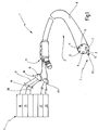
- an endoscope system 1 according to an embodiment of the invention with a flexible endoscope 2, a working instrument 3 inserted in the endoscope 2 and a control device 4 is illustrated in a highly schematic representation.
- the endoscope system 1 is intended to carry out argon plasma coagulation (APC) to stop bleeding from lesions (injuries), in particular of the gastrointestinal tract, whereby the invention can also be used in other medical endoscopic systems.
- APC argon plasma coagulation
- a flexible endoscope 2 is shown here, for example, a rigid endoscope 2 can also be used in other applications.
- the endoscope system according to the invention can be used for various other treatments or operations, for example for desiccation of a tissue surface, erodication of remains after a polypectomy, for scabbing or for thermal tissue marking.
- the endoscope 2 here has an elongated, bendable tube or flexible tube 6 made of a suitable biocompatible, flexible material, in particular polymer material, such as, for example, polytetrafluoroethylene (PTFE), which is suitable for use inside a patient's body.
- the hose 6 defines a working channel 7 into which different working instruments can be used.
- the surgical working instrument 3 is accommodated displaceably in the working channel 7 of the endoscope 1, protruding out of the working channel 7 from a distal end 8 of the endoscope 2, which is intended for insertion into a patient's body.
- an optional further working channel 9 is also led out, which can be used for other working instruments if necessary.
- a lens or observation device 11 is arranged at the distal end 8 of the endoscope 2, which has a Include CCD camera or can be connected to an eyepiece device, not shown here, via a fiberglass strand.
- the endoscope 2 contains a lighting device 12 with lighting means that protrude outward at the distal end 8 of the endoscope 1 and are connected to a light source, preferably cold light source, via an optical waveguide, in order to receive high-intensity light in the visible spectral range during use to direct a treatment or operation area not shown here inside a patient.
- a light source preferably cold light source
- an optical waveguide in order to receive high-intensity light in the visible spectral range during use to direct a treatment or operation area not shown here inside a patient.
- the working instrument 3 can be pushed into a proximal end 13 of the endoscope 2 until it, as in FIG Figure 1 illustrates, emerges from the distal end 8 of the working channel 7. In this position, a distal end 14 of the working instrument 3 is located in the field of view of the observation device 11 of the endoscope 2 that can be illuminated by the illumination device 12.
- a proximal end 16 of the working instrument 3 is connected to the control device 4 via a connector or plug 15.
- the connector 15 comprises a gas supply line 17 via which the working instrument 3 is in flow connection with a gas supply device 18 of the control device 4.
- the gas supply device 18 is connected to a gas supply, for example a gas cylinder containing argon, and is set up to supply the gas, for example argon, with a predetermined for to supply appropriate pressure to the working instrument 3 for the respective treatment.
- the connector 15 also includes an electrical connection line 19, via which the working instrument 3 is electrically conductively connected to a high-frequency (HF) generator device 21 of the control device 4 in order to generate a required HF voltage from this to ignite a plasma discharge to ionize the inert gas, e.g. argon, for supplying coagulation current to the tissue.
- a high-frequency (HF) generator device 21 of the control device 4 for supplying coagulation current to the tissue.
- an electrode 22, which is connected to the connecting line 19, is provided at the distal end 14 of the working instrument 3.
- the electrode 22 is shown here as a pin-shaped or tubular ignition electrode, but can assume any shape, for example that of an ignition plate.
- the electrode 22 can also be arranged in an attachment piece or head part (not shown here) of the working instrument 3, which can be made of ceramic, for example, in order to withstand the effects of heat due to the ignited plasma discharge during operation.
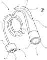
- the surgical working instrument 3 is shown in FIG Figure 2 shown in an isolated, simplified perspective view and in Figure 3 in a schematic longitudinal sectional view.
- the working instrument 3 which is also referred to as a probe, has a tube 23, which is designed here in the form of a flexible hose and is made of a suitable, biocompatible material that is suitable for the present applications, in particular of PTFE, is trained.
- a rigid tube 23 could also be used with a rigid endoscope.
- the tube 23 has a wall 24 which defines an essentially cylindrical inner channel 26, also referred to as a lumen, through which the gas, for example argon, is supplied to the distal end 14 of the working instrument 3 will.
- the connecting line 19, which extends from the proximal end 16 of the working instrument 3 to its distal end 14 and is connected to the electrode 22 there, is also accommodated in the inner channel 26.
- the electrode 22 of the working instrument 3 it is important to position the electrode 22 of the working instrument 3 at a suitable relative position in relation to the endoscope 2 during use.
- the electrode 22 should be positioned at a minimum distance from the distal end 8 of the endoscope 2 so that after the ignition of the plasma discharge, if the ionized gas serves as a conductor for supplying the coagulation current, the resulting heat does not impair the endoscope 2.
- the working instrument 3 can be intended for single use, so that it is manufactured relatively inexpensively and is thrown away after an endoscopic treatment or operation.
- the endoscope with its components is relatively expensive and intended for reuse.
- components arranged at the distal end 8 of the endoscope 2 in particular such as the observation device 11, the illumination device 12 and the like, must be protected against damage by the heat developed during operation.
- a minimum distance between the APC probe tip with the electrode 22 and the distal end 14 of the endoscope 2 of at least about 10 mm is required.
- the electrode 22 should not protrude too far out of the working channel 7 of the endoscope 2 so that it is arranged in the illumination field of the illumination device 12 and in the field of view of the observation device 11 during operation and also undesired contact with the tissue surface to be treated by the electrode 22 with the corresponding risk injury can be avoided.
- a suitable positioning of the probe tip relative to the endoscope end should be ensured in order, for example, to enable efficient endoscopic treatment or a session or to avoid undesired contact of an optical system or an instrument on the probe tip with the tissue.
- a position detection device 27 is provided.
- the position detection device 27 has a light guide 28 which is anchored to the working instrument 3 and is set up to pick up light that surrounds the working instrument 3 in the vicinity of its distal end 14, the light picked up by the light guide 28 determining the relative position of the Working instrument 3 to the endoscope 2 can be determined.
- the light guide 28 is firmly anchored to the working instrument 3 in such a way that it can be introduced together with the working instrument 3 into the working channel 7 of the endoscope 1 and can be displaced therein. Starting from a point near the distal end 14 of the working instrument 3, the light guide can extend to the proximal end 16 in order to guide the light received from the environment to the proximal end of the working instrument 3 for evaluation.
- the light guide 28 can comprise any optical fiber, for example glass fiber or, preferably, a polymeric optical fiber. There are relatively inexpensive optical fibers available which are suitable for the present position detection function, for which there is no highest quality, absolute lossless light detection and transmission is required.
- the light guide 28 is largely accommodated in the inner channel 26 of the working instrument 3.
- the light guide 28 has a first end 29, which is fastened to the tube 23 of the instrument 3, a second end 31, which is led out over the proximal end 16 of the tube 23, and a light guide middle section 32 extending therebetween, which is essentially in the inner channel 26 is housed.
- the first end 29 of the light guide 28 protrudes through the wall 24 of the tube 23 and has an end face 33 which is oriented radially or laterally outward with respect to the longitudinal axis of the working instrument 3, not shown here.
- the end face 33 forms a light introduction surface in order to detect external light on the outside of the tube 23 and to guide it into the light guide 28. The detected light is then transmitted via the middle section 32 of the light guide to the second end 31 of the light guide 28.
- the first end 29 of the light guide 28 is received in a form-fitting manner in an opening 34 which is incorporated in the flexible tube 23 and can additionally be secured therein, for example by gluing.
- the end face 33 of the light guide 28, which serves as the light introduction face, preferably ends essentially flush with the outside of the tube 23.
- the tube 23 itself consists of an opaque material.
- the second end 31 of the light guide 28 is connected to an evaluation device 36, which can be connected or connected to the proximal end 16 of the working instrument 3 and is set up to receive and evaluate the light received by the light guide 28 in order to determine the relative position of the working instrument 3 determine.
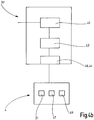
- Embodiments of the Evaluation device 36 are shown in simplified block diagram representations in Figures 4a and 4b illustrated in more detail.
- the evaluation device can have a spectrometer unit 37, an electro-optical converter 38, a signal conditioning unit 39, a spectrum analysis unit 41, a memory 42, a detector unit 43, an output unit 44 and an interface 46.
- the units 37-46 are shown here as separate blocks, they only form functional units that are contained in one or more physical units, distributed over different units, implemented in hardware and / or software and at least partially embodied by logic, which can be implemented in the form of a code for execution on a processor not shown here in order to fulfill the function of the evaluation device 36 for evaluating the light received from the light guide 28 and for recognizing the relative position of the instrument 3.
- the spectrum analysis unit 41 is set up to evaluate the electrical signals that represent the spectrally split light components in order to determine the spectral components of the light or the intensities of the light in different light frequency ranges or at the specific discrete frequencies and to compare them with stored reference spectra in order to to classify or identify the light picked up by the light guide based on the comparison.
- the reference spectra can be determined in advance and stored in the memory 42 in advance.
- a reference spectrum for the cold light of the endoscope 3, for the ambient light of a work space and for the plasma light resulting from the spark discharge during APC coagulation can be stored. All of these light sources have characteristic spectra which clearly differ from one another with regard to the respective frequency range and the intensity values therein.
- ambient light from a work space will have wavelengths in the range of 300-1100 nm with a characteristic first intensity distribution
- the work light from a cold light source of the endoscope generally comprises a wavelength range of 400-700 nm or a subrange therein and has a second characteristic intensity distribution and the light emitted by the plasma has characteristic components both in the visible wavelength range and in the range of 200-400 nm with a different, third intensity distribution.
- One or more of the ambient light, the cold light of the endoscope and / of the light emitted by the plasma can also be detected empirically in order to determine and store the associated reference spectra therefrom.
- representative frequency spectra provided by the manufacturers of the respective lights or devices are obtained, or simulated light spectra are used as reference spectra.
- the spectrum analysis unit 41 is able, by comparing intensity values of certain discrete frequency lines or frequency ranges in different frequency bands, to determine whether light was received through the light guide 28 or not, and if so, whether it is the cold light of the lighting device 12 of the Endoscope 2, the ambient light of the examination or treatment room or a light signal due to the spark discharge.
- the detector unit 43 monitors the type of light identified by the spectrum analysis unit and is set up to detect when the working instrument 3 is inserted into the working channel 7 of the endoscope 2 when the light introduction surface, in particular the end surface 33 of the light guide 28, is exposed to the surroundings of the treatment room, enters the proximal end 13 of the working channel 7 from the surroundings or emerges from the working channel 7 into a body area to be treated.
- the detector unit 43 Based on this detection, the detector unit 43 generates corresponding position detection signals which, for example, identify the beginning of the insertion of the working instrument 3 into the working channel 7 or indicate that the distal end 14 of the instrument 3 protrudes beyond the distal end 8 of the endoscope 2 by the desired distance, which corresponds to the distance between the distal end 14 of the working instrument 3 and the light introduction surface 33.
- the optional output unit 44 can be connected to the detector unit 43 in order to receive the position detection signals therefrom and convert them into optical, acoustic or tactile display signals that can be perceived by an operator of the surgical working instrument 3.
- the operator is able to recognize when that Working instrument 3 is positioned in the desired relative working position in relation to endoscope 2.
- the detector unit 43 can alternatively or additionally be connected via the interface 46 to the control device 4 of the endoscope system 1, which receives the position detection signals from the detector unit 43 and automatically initiates suitable measures based thereon, for example an activation lock, a preactivation, a parameterization and / or a control of the operation of the working instrument 3 and / or the endoscope 2 can bring about.
- suitable measures for example an activation lock, a preactivation, a parameterization and / or a control of the operation of the working instrument 3 and / or the endoscope 2 can bring about.
- Figure 4b shows a further, particularly preferred embodiment of an evaluation device 36 ', which is implemented with very few complexes and can be set up for a greatly simplified evaluation of the light received by the light guide 28 for rough position determination.
- the evaluation device 36 ' can only enable the detection of the presence and absence of the recorded light or a light-dark distinction.
- the evaluation device 36 'in this case can have a means 40 for converting the recorded light signal into an electrical signal, in particular a photodiode, and a detector unit 43' which forms a light-dark detector.
- the interface 44, 46 additionally shown in FIG. 4b can, in the simplest case, be a connection line, a plug pin or a plug socket.
- the endoscope system 1 works as follows: If argon plasma coagulation is to be carried out, the operator can select the desired mode via the control device 4, whereby components of the endoscope system 1, including the position detection device 27, can be activated.
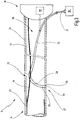
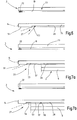
- the position recognition device 27 recognizes via the light received by the light guide 28 after evaluation by the evaluation device 36 or 36 'that the probe 3 is still outside the endoscope 2, as in FIG Figure 5a Illustrates, and is exposed to the ambient light of the treatment room.
- the detector unit 43 determines, for example, that the determined frequency spectrum of the received light matches the reference spectrum of the ambient light at least at certain discrete frequencies, at least clearly from the reference spectra of the cold light source of the endoscope 2 and the light signal emitted by the plasma distinguishes and reports a corresponding position signal via the interface 44 or 46.
- the light-dark detector unit 43 'reports a brightness signal.
- position signals are mentioned here, the light and dark signals generated by the light-dark detector device 40, 43 'are also to be understood as such.
- the control device 4 can then, if not already done, bring about a preactivation of the endoscope system 1, including a parameterization of the HF generator device 21, switching on the lighting device 12 and presetting of control valves for the gas supply.
- the inert gas supply can already be started as soon as it is recognized that the working instrument 3 is being inserted into the working channel 7, in order to enable the working instrument 3 to be kept clean during the insertion process.
- the distal end 14 of the probe 3 exits the distal end 8 of the endoscope 2 so far that the end face 33 of the light guide 28 leaves the working channel 7, as illustrated in FIG at the distal end 8 of the endoscope 2 to illuminate the treatment or operating area is broadcast.
- This light is supplied by a suitable cold light source 47, which, for example, can be integrated in the control device 4 or can also be an external light source.
- the evaluation device 36 or 36 'of the position detection device 27 receives the light signal via the light guide 28 and detects the abrupt change between the absent and the present light signal. For example, the light-dark detector 43 'detects the dark-light transition and reports a brightness signal again.
- the spectrum analysis unit 41 can determine the frequency spectrum of the recorded light and, using reference spectra stored in the memory 42, determine that the recorded light is the work light, i.e. the cold light of the endoscope 2. Via the output unit 44, the detector unit 43 or 43 'can then output the corresponding position recognition signal for the operator, who can consequently recognize that the probe tip with the electrode 22 has now reached the desired target position, so that the working instrument 3 can no longer be advanced should.
- the position detection signal can alternatively or additionally be transmitted via the interface 46 to the control device 4, which can then cancel the activation lock for the electrical HF signal and also automatically start controlling the operation of the working instrument 3.
- the supply of the gas to be ionized, for example argon to the working instrument 3 can be triggered automatically and the ignition of a plasma discharge through the electrode 22 can be released.
- the HF generator device 22 can thus supply the required HF voltage signal via the connecting line 19 to the electrode 22 in order to enable the plasma discharge to be ignited and the gas to be ionized, after which the argon plasma generated is used as a conductor to transmit the coagulation current to the tissue to be treated.
- the treated area can be recorded via the optics 11, for example a CCD camera, and the image signals can be fed to an image processing unit 49 of the control device 4 via an optical waveguide 48 in order to be shown to the operator on a display not shown in detail here.
- control device 4 can then automatically stop the operation of the working instrument 3 and effect an activation lock in order to interrupt the gas and / or HF voltage supply, so that the spark discharge is stopped and damage to the endoscope 2 is prevented.
- the action of repeatedly pushing the working instrument 3 into and out of the working channel 7 could also be carried out in a targeted manner by the operator in order to identify the exact location of the desired working position for the working instrument 3.
- the activation or cancellation of the activation lock can be delayed as long as the operator is still making settings.
- the evaluation device 36 or 36 ′ can thus be accommodated in a device unit separate from the working instrument 3, for example in the control device 4.
- parts, for example parts of the evaluation device 36 or 36 'that can be implemented in hardware, can be accommodated in the connector 15 which connects the Forms the interface to the external control device 4, while other parts, in particular parts of the evaluation device 36 or 36 'that can be implemented in firmware or software, can be implemented, for example, in the control device 4 or another external device.
- the evaluation device 36 ' is according to Figure 4b with the detector device formed by the photodiode 40 and the light-dark detector 43 'completely housed in the connector 15, which is arranged at the proximal end 16 of the working instrument 3 and is used for connection to the control device 4.
- the control device 4 As a result, an extremely compact, largely independent unit consisting of the working instrument 3 and the associated position detection device 27 can be provided, which is well suited for use as a single-use probe, because the relatively inexpensive detector device 40, 43 'with few complexes can be disposed of after a single use.
- the light-dark detector device integrated in the connector 15 can follow the evaluation device 36 ' Figure 4b only contain the photodiode 40 or some other means for converting the received light into an electrical signal.
- the electrical signal can then be transmitted to the external control device 4 via the interface 46 for threshold filtering and / or evaluation.
- the functionality of the light-dark detector unit 43 'in Figure 4b can be relocated to the control unit 4, which further reduces the effort and the costs for the evaluation device 36 'built into the connector 15.
- FIGS Figures 6 and 7a, 7b Further embodiments of the position detection device 27 according to the invention are shown in FIGS Figures 6 and 7a, 7b illustrated. Insofar as there is a correspondence in the structure and / or in the mode of operation, reference is made to the above description based on the same reference numerals.
- Figure 6 shows an embodiment in which the light guide 28 is not arranged in the inner channel 26 of the tube 23 of the working instrument 3, but on the outside 51 of the wall 24.
- the light guide 28 can have a beveled end face or fiber facet 52, which serves as a light introduction surface in order to capture the surrounding light at the distal end 14 of the working instrument 3 and to guide it into the light guide middle section 32, which carries the light on to the proximal end 16 of the Working instrument 3 transfers.
- the beveled end face 52 is directed both radially or laterally outwards and in the longitudinal direction of the instrument 3, preferably towards the distal end 14.
- the middle section 32 of the light guide 28 extends, starting from the inclined end face 52, essentially in a straight line along the tube 23 on its outer side 51 and can be attached to the outer side 51, for example by gluing.
- attachment to the outside is made easier than it is to be accommodated in the inner channel 26 of the working instrument 3.
- the mode of operation of the position detection device 27 in the embodiment according to FIG Figure 6 corresponds to that in connection with the Figures 1-5 described above.
- Figures 7a and 7b show yet another embodiment of the position detection device 27 according to the invention, wherein
- the light introduction surface for capturing the light surrounding the working instrument 3 is formed by a separate light introduction element, namely in the example shown by an elongated glass rod 53.
- the glass rod 53 which can be formed from silicate glass or acrylic glass, is arranged on the outside 51 of the tube 23 and attached to it and / or embedded therein.
- the elongated glass rod 53 has a length which is greater than its width and is aligned along the longitudinal extension of the working instrument 3.
- the length of the glass rod 53 can be as desired, preferably greater than half the projection length of the distal end 14 of the working instrument 3 in the desired working position or as the distance between the distal end 14 of the working instrument 3 and the distal end of the glass rod 53.
- the radially or laterally outwardly facing outer surface 54 of the glass rod 53 serves as the light introduction surface.
- a front end 56 of the glass rod 53 facing away from the distal end 14 of the working instrument 3 is connected to a front end 57 of the light guide 28 so that the light received by the glass rod 53 enters the light guide 28 and through it to the proximal end 16 of the working instrument 3 is transferred out.
- FIGS. 7a, 7b The mode of operation of the working instrument 3 and the position detection device 27 in the embodiment according to FIGS. 7a, 7b largely corresponds to that of the embodiments described above, but here a more precise determination of the relative position of the working instrument 3 in relation to the endoscope 2 is possible.
- Figure 7a the state of the desired positioning of the working instrument 3, in which the distal end 14 of the working instrument 3 has stepped out of the working channel 7 to such an extent that the electrode 22 is at the desired distance from the distal end 8 of the endoscope 2.
- the glass rod 53 is pushed completely out of the working channel 7, so that a high-intensity light signal is received via the light guide 28 and fed to the position detection device 27.
- the evaluation device 36 or 36 'recognizes the light signal of the maximum intensity, for example on the basis of a maximum of several thresholds, and then generates a position recognition signal which indicates that the working instrument 3 is now in the desired working position.
- FIG. 7b a state is shown in which the distance between the distal end 14 or the electrode 22 of the working instrument 3 and the distal end 8 of the endoscope 2 is smaller than the desired distance.
- This state can be present either when inserting the working instrument 3 into the working channel 7 in preparation for an APC coagulation or other endoscopic treatment or examination or during operation if the operator, for example, accidentally pulls the working instrument 3 back at least partially into the working channel 7.
- the tube 6 of the endoscope 2 covers at least a section of the outer surface 54 of the glass rod 53, so that only a reduced amount of light is captured via the glass rod 53 and introduced into the light guide 28.
- the evaluation device 36 or 36 'detects the reduced intensity of the recorded light and in this case can, for example, initiate or maintain the activation lock in order to prevent the endoscope 2 or whose components will be damaged.
- a surgical working instrument 3 is disclosed, which is inserted into a working channel 7 of an endoscope 2 and received therein in a displaceable manner.
- a device 27 for recognizing the relative position of the working instrument 3 to the endoscope 2 is set up to optically detect when a distal end 8 of the working channel 7 is reached by a distal end 8 of the working instrument 3.
- the position detection device 27 has a light guide 28 which is anchored to the working instrument 3 and is set up to pick up light that surrounds the working instrument 3 in the vicinity of its distal end 14, the light picked up by the light guide 28 determining the relative position of the Light guide 28 and thus the working instrument 3 to the endoscope 2 can be determined.
Priority Applications (6)
| Application Number | Priority Date | Filing Date | Title |
|---|---|---|---|
| EP20155627.1A EP3861920A1 (fr) | 2020-02-05 | 2020-02-05 | Instrument chirurgical doté d'un dispositif de détection de la position |
| BR102021001560-8A BR102021001560A2 (pt) | 2020-02-05 | 2021-01-27 | Instrumento cirúrgico com um dispositivo detector de posição |
| US17/166,502 US11974797B2 (en) | 2020-02-05 | 2021-02-03 | Surgical instrument having a position detection device |
| JP2021015593A JP2021129981A (ja) | 2020-02-05 | 2021-02-03 | 位置検出デバイスを備えた手術器具 |
| KR1020210015947A KR20210100030A (ko) | 2020-02-05 | 2021-02-04 | 위치 검출 장치를 구비한 수술 기구 |
| CN202110160600.4A CN113208664A (zh) | 2020-02-05 | 2021-02-05 | 具有位置检测装置的外科器械 |
Applications Claiming Priority (1)
| Application Number | Priority Date | Filing Date | Title |
|---|---|---|---|
| EP20155627.1A EP3861920A1 (fr) | 2020-02-05 | 2020-02-05 | Instrument chirurgical doté d'un dispositif de détection de la position |
Publications (1)
| Publication Number | Publication Date |
|---|---|
| EP3861920A1 true EP3861920A1 (fr) | 2021-08-11 |
Family
ID=69500595
Family Applications (1)
| Application Number | Title | Priority Date | Filing Date |
|---|---|---|---|
| EP20155627.1A Pending EP3861920A1 (fr) | 2020-02-05 | 2020-02-05 | Instrument chirurgical doté d'un dispositif de détection de la position |
Country Status (6)
| Country | Link |
|---|---|
| US (1) | US11974797B2 (fr) |
| EP (1) | EP3861920A1 (fr) |
| JP (1) | JP2021129981A (fr) |
| KR (1) | KR20210100030A (fr) |
| CN (1) | CN113208664A (fr) |
| BR (1) | BR102021001560A2 (fr) |
Families Citing this family (3)
| Publication number | Priority date | Publication date | Assignee | Title |
|---|---|---|---|---|
| EP3861920A1 (fr) * | 2020-02-05 | 2021-08-11 | Erbe Elektromedizin GmbH | Instrument chirurgical doté d'un dispositif de détection de la position |
| WO2023149885A1 (fr) * | 2022-02-03 | 2023-08-10 | C.R. Bard, Inc. | Dispositifs et systèmes d'urétéroscope ayant un capteur de position de pointe de fibre |
| EP4344662A1 (fr) * | 2022-09-27 | 2024-04-03 | Erbe Elektromedizin GmbH | Procédé de contrôle d'une orientation d'une extrémité distale d'un guide d'ondes optiques et dispositif de contrôle pour la mise en oeuvre du procédé |
Citations (5)
| Publication number | Priority date | Publication date | Assignee | Title |
|---|---|---|---|---|
| DE4139029C2 (de) | 1991-11-27 | 1996-05-23 | Erbe Elektromedizin | Einrichtung zur Koagulation biologischer Gewebe |
| DE19731931A1 (de) | 1997-07-24 | 1999-02-11 | Erbe Elektromedizin | Einrichtung zur HF-Koagulation biologischer Gewebe mittels flexibler Endoskopie |
| DE102004039202B3 (de) | 2004-08-12 | 2006-01-19 | Erbe Elektromedizin Gmbh | Vorrichtung zur Messung einer relativen Position eines chirurgischen Arbeitsinstruments sowie Verwendung hierfür |
| US20100152538A1 (en) * | 2008-12-17 | 2010-06-17 | Gleason Christopher M | Device for preventing endoscope damage by errant laser fire in a surgical laser |
| US20100179417A1 (en) * | 2005-06-20 | 2010-07-15 | Susan Russo | Medical tube system with position sensing |
Family Cites Families (24)
| Publication number | Priority date | Publication date | Assignee | Title |
|---|---|---|---|---|
| US5720745A (en) | 1992-11-24 | 1998-02-24 | Erbe Electromedizin Gmbh | Electrosurgical unit and method for achieving coagulation of biological tissue |
| WO1994015533A2 (fr) | 1993-01-18 | 1994-07-21 | John Crowe | Forceps pour endoscopes |
| US5906630A (en) | 1998-06-30 | 1999-05-25 | Boston Scientific Limited | Eccentric surgical forceps |
| AU2003275081A1 (en) * | 2002-09-20 | 2004-04-08 | Sherwood Sevices Ag | Electrosurgical instrument for fragmenting, cutting and coagulating tissue |
| US20060217594A1 (en) | 2005-03-24 | 2006-09-28 | Ferguson Gary W | Endoscopy device with removable tip |
| US8989528B2 (en) * | 2006-02-22 | 2015-03-24 | Hansen Medical, Inc. | Optical fiber grating sensors and methods of manufacture |
| JP5341884B2 (ja) | 2007-06-12 | 2013-11-13 | コーニンクレッカ フィリップス エヌ ヴェ | 画像ガイドされる治療 |
| EP2626006B1 (fr) * | 2007-08-14 | 2019-10-09 | Koninklijke Philips N.V. | Systèmes d'instruments robotisés utilisant des capteurs à fibres optiques |
| US8037591B2 (en) | 2009-02-02 | 2011-10-18 | Ethicon Endo-Surgery, Inc. | Surgical scissors |
| JP5065538B2 (ja) * | 2010-09-14 | 2012-11-07 | オリンパスメディカルシステムズ株式会社 | 内視鏡システム及び視界不良判定システムの動作方法 |
| CN102128812B (zh) | 2010-12-29 | 2013-05-15 | 重庆大学 | 基于激光远距离供能的痕量气体检测装置和方法 |
| JP5959150B2 (ja) | 2011-01-12 | 2016-08-02 | オリンパス株式会社 | 内視鏡システム |
| JP6259661B2 (ja) * | 2011-01-28 | 2018-01-10 | コーニンクレッカ フィリップス エヌ ヴェKoninklijke Philips N.V. | 光学的追跡システム |
| JP5881307B2 (ja) | 2011-04-08 | 2016-03-09 | オリンパス株式会社 | 外光を利用した挿入部先端位置検出が可能な観察装置 |
| WO2013043344A1 (fr) * | 2011-09-21 | 2013-03-28 | Boston Scientific Scimed, Inc. | Systèmes et procédés de prévention d'un allumage intempestif de fibres laser au sein de dispositifs d'accès endoscopiques |
| EP2804527B1 (fr) | 2012-01-26 | 2021-04-14 | Autonomix Medical, Inc. | Système de sympathectomie et de micro-ablation contrôlées |
| UA112226C2 (uk) * | 2012-05-25 | 2016-08-10 | Фосс Аналітікал А/С | Оптичний спектрометр |
| JP2013244313A (ja) | 2012-05-29 | 2013-12-09 | Konica Minolta Inc | 光測定装置 |
| US9888919B2 (en) | 2013-03-14 | 2018-02-13 | Ethicon Llc | Method and system for operating a surgical instrument |
| JP5959723B2 (ja) * | 2013-03-29 | 2016-08-02 | 富士フイルム株式会社 | 内視鏡下外科手術装置 |
| EP3189768B1 (fr) * | 2014-09-05 | 2019-04-17 | Olympus Corporation | Système d'endoscope |
| CN104825121B (zh) | 2015-05-08 | 2017-04-26 | 南京微创医学科技股份有限公司 | 内窥式oct微探头、oct成像系统及使用方法 |
| IL246068A0 (en) | 2016-06-06 | 2016-08-31 | Medigus Ltd | Endoscope-like devices that contain sensors that provide location information |
| EP3861920A1 (fr) * | 2020-02-05 | 2021-08-11 | Erbe Elektromedizin GmbH | Instrument chirurgical doté d'un dispositif de détection de la position |
-
2020
- 2020-02-05 EP EP20155627.1A patent/EP3861920A1/fr active Pending
-
2021
- 2021-01-27 BR BR102021001560-8A patent/BR102021001560A2/pt unknown
- 2021-02-03 US US17/166,502 patent/US11974797B2/en active Active
- 2021-02-03 JP JP2021015593A patent/JP2021129981A/ja active Pending
- 2021-02-04 KR KR1020210015947A patent/KR20210100030A/ko active Search and Examination
- 2021-02-05 CN CN202110160600.4A patent/CN113208664A/zh active Pending
Patent Citations (5)
| Publication number | Priority date | Publication date | Assignee | Title |
|---|---|---|---|---|
| DE4139029C2 (de) | 1991-11-27 | 1996-05-23 | Erbe Elektromedizin | Einrichtung zur Koagulation biologischer Gewebe |
| DE19731931A1 (de) | 1997-07-24 | 1999-02-11 | Erbe Elektromedizin | Einrichtung zur HF-Koagulation biologischer Gewebe mittels flexibler Endoskopie |
| DE102004039202B3 (de) | 2004-08-12 | 2006-01-19 | Erbe Elektromedizin Gmbh | Vorrichtung zur Messung einer relativen Position eines chirurgischen Arbeitsinstruments sowie Verwendung hierfür |
| US20100179417A1 (en) * | 2005-06-20 | 2010-07-15 | Susan Russo | Medical tube system with position sensing |
| US20100152538A1 (en) * | 2008-12-17 | 2010-06-17 | Gleason Christopher M | Device for preventing endoscope damage by errant laser fire in a surgical laser |
Also Published As
| Publication number | Publication date |
|---|---|
| KR20210100030A (ko) | 2021-08-13 |
| US11974797B2 (en) | 2024-05-07 |
| BR102021001560A2 (pt) | 2021-08-17 |
| US20210236187A1 (en) | 2021-08-05 |
| CN113208664A (zh) | 2021-08-06 |
| JP2021129981A (ja) | 2021-09-09 |
Similar Documents
| Publication | Publication Date | Title |
|---|---|---|
| EP3861920A1 (fr) | Instrument chirurgical doté d'un dispositif de détection de la position | |
| DE19542955C2 (de) | Endoskop | |
| EP1618836B1 (fr) | Laryngoscope avec tomographie à cohérence optique | |
| EP0861044B1 (fr) | Dispositif de diagnostic photodynamique | |
| EP3685781B1 (fr) | Dispositif de coagulation de tissu | |
| DE10116056A1 (de) | Endoskopische Visualisierungsvorrichtung mit unterschiedlichen Bildsystemen | |
| DE102006022827A1 (de) | Endoskop | |
| DE102005014530A1 (de) | Endoskop | |
| EP3560409B1 (fr) | Dispositif pour la manipulation stérile d'un endoscope non stérile dans un environnement stérile | |
| EP1680037B1 (fr) | Instrument medical muni d'un endoscope | |
| DE102005019143A1 (de) | Kombiniertes diagnose- und therapieunterstützendes System | |
| DE19638809C2 (de) | Vorrichtung zur Prüfung eines PDD- oder PDT-Systems und/oder zur Schulung an einem derartigen System | |
| EP2238887A1 (fr) | Dispositif destiné au diagnostic par fluorescence | |
| EP1781159A2 (fr) | Dispositif pour mesurer la position d'un instrument de travail chirurgical | |
| EP1447043A1 (fr) | Dispositif pour le diagnostic biologique de tissus | |
| EP3560410B1 (fr) | Dispositif pour la manipulation stérile d'un endoscope non stérile dans un environnement stérile | |
| JP3796805B2 (ja) | 内視鏡用処置具 | |
| EP2452615A1 (fr) | Système de médecine dentaire destiné à transilluminer des dents | |
| EP3868317A1 (fr) | Système médical, source de milieu ou d'énergie et trocart | |
| DE102009052524B4 (de) | Endoskopset | |
| DE102010027905B4 (de) | Videoendoskopsystem und Verfahren zum Betreiben eines Videoendoskopsystems | |
| EP1269909A1 (fr) | Procédé et dispositif de reconnaissance des changements pathologiques sur la surface des tissus, notamment des dents | |
| EP3727125A2 (fr) | Endoscope | |
| EP3387983A2 (fr) | Endoscope avec un capteur de mesure d'un parametre physique | |
| DE102021122841A1 (de) | Verfahren zum Betreiben eines chirurgischen Systems |
Legal Events
| Date | Code | Title | Description |
|---|---|---|---|
| PUAI | Public reference made under article 153(3) epc to a published international application that has entered the european phase |
Free format text: ORIGINAL CODE: 0009012 |
|
| STAA | Information on the status of an ep patent application or granted ep patent |
Free format text: STATUS: THE APPLICATION HAS BEEN PUBLISHED |
|
| AK | Designated contracting states |
Kind code of ref document: A1 Designated state(s): AL AT BE BG CH CY CZ DE DK EE ES FI FR GB GR HR HU IE IS IT LI LT LU LV MC MK MT NL NO PL PT RO RS SE SI SK SM TR |
|
| STAA | Information on the status of an ep patent application or granted ep patent |
Free format text: STATUS: REQUEST FOR EXAMINATION WAS MADE |
|
| 17P | Request for examination filed |
Effective date: 20211126 |
|
| RBV | Designated contracting states (corrected) |
Designated state(s): AL AT BE BG CH CY CZ DE DK EE ES FI FR GB GR HR HU IE IS IT LI LT LU LV MC MK MT NL NO PL PT RO RS SE SI SK SM TR |
|
| STAA | Information on the status of an ep patent application or granted ep patent |
Free format text: STATUS: EXAMINATION IS IN PROGRESS |