EP3860410B1 - Verfahren zur ausgabe eines heissgetränks - Google Patents
Verfahren zur ausgabe eines heissgetränks Download PDFInfo
- Publication number
- EP3860410B1 EP3860410B1 EP19805730.9A EP19805730A EP3860410B1 EP 3860410 B1 EP3860410 B1 EP 3860410B1 EP 19805730 A EP19805730 A EP 19805730A EP 3860410 B1 EP3860410 B1 EP 3860410B1
- Authority
- EP
- European Patent Office
- Prior art keywords
- compressed gas
- valve
- brewing
- hot water
- hot
- Prior art date
- Legal status (The legal status is an assumption and is not a legal conclusion. Google has not performed a legal analysis and makes no representation as to the accuracy of the status listed.)
- Active
Links
Images


Classifications
-
- A—HUMAN NECESSITIES
- A47—FURNITURE; DOMESTIC ARTICLES OR APPLIANCES; COFFEE MILLS; SPICE MILLS; SUCTION CLEANERS IN GENERAL
- A47J—KITCHEN EQUIPMENT; COFFEE MILLS; SPICE MILLS; APPARATUS FOR MAKING BEVERAGES
- A47J31/00—Apparatus for making beverages
- A47J31/002—Apparatus for making beverages following a specific operational sequence, e.g. for improving the taste of the extraction product
-
- A—HUMAN NECESSITIES
- A47—FURNITURE; DOMESTIC ARTICLES OR APPLIANCES; COFFEE MILLS; SPICE MILLS; SUCTION CLEANERS IN GENERAL
- A47J—KITCHEN EQUIPMENT; COFFEE MILLS; SPICE MILLS; APPARATUS FOR MAKING BEVERAGES
- A47J31/00—Apparatus for making beverages
- A47J31/24—Coffee-making apparatus in which hot water is passed through the filter under pressure, i.e. in which the coffee grounds are extracted under pressure
- A47J31/34—Coffee-making apparatus in which hot water is passed through the filter under pressure, i.e. in which the coffee grounds are extracted under pressure with hot water under liquid pressure
- A47J31/36—Coffee-making apparatus in which hot water is passed through the filter under pressure, i.e. in which the coffee grounds are extracted under pressure with hot water under liquid pressure with mechanical pressure-producing means
Definitions
- the Invention relates to a method for the dispensing of a hot beverage and a device for implementing the method.
- a number of different parameters are taken into consideration in the brewing of hot beverages in modern beverage vending machines.
- the degrees of roasting and grinding of the coffee beans, the ratio of coffee powder to hot water, or the duration of the brewing process are taken into account for this purpose.
- parameters such as the temperature of the hot water, the pressure inside the brewing chamber, or the type of filter are selected in a targeted manner, based on their effects on the taste of a finished coffee drink.
- the concentration of the coffee solution is decisive for the taste of a coffee drink.
- the latter corresponds to the amount of dissolved coffee in relation to the hot water and determines the strength of a coffee.
- the concentration of a coffee depends on how much coffee powder is used for the brewing process and what proportion of the coffee powder is dissolved in the hot water.
- the proportion by weight of the coffee powder, which is used for the brewing process and which is dissolved in water, is designated in this connection as extraction and increases with increasing duration of the brewing process. With increasing duration of the brewing process, however, increasingly more undesired bitter substances are also leached out of the coffee powder and transferred to the liquid.
- the quantity of coffee powder being brewed In order to increase the concentration of a coffee drink, accordingly, on the one hand, the quantity of coffee powder being brewed, and, on the other hand, the duration of the brewing process can be increased. In order to avoid an increased quantity of bitter substances in the finished coffee drink due to a long brewing time, the quantity of coffee powder is usually increased instead of the brewing time, so as to obtain the desired concentration.
- the optimal concentration for black coffee for example, lies between 1.30 wt.% and 1.55 wt.%, and the optimal extraction lies between 18 wt.% and 22 wt.%, in each case referred to the total weight of the finished hot beverage.
- WO 2016/164796 A1 discloses a brewing apparatus for preparing and dispensing a cold beverage which comprises a brewing chamber, to which an inert gas is supplied. The document does not disclose to supply compressed air with an adjustable delay after starting the brewing process.
- Another object of the disclosure is to create a device for implementing the method.
- a device for implementing the method according to the disclosure which is designated also in the following as a beverage vending machine, comprises a hot water generating system for the generation of hot water and a brewing chamber, as is described in detail, e.g., in the 10 above-mentioned EP 1 005 821 B1 .
- the brewing chamber is filled with the brewing material, i.e., coffee powder or espresso powder or tea, and, after this, it is loaded with hot water via a hot water inlet.
- the hot beverage is delivered from the brewing chamber into a vessel via a hot beverage outlet and a drain line connected therewith.
- the method is characterized in that the hot beverage outlet is loaded with compressed gas from a compressed gas source during a brewing process, wherein the compressed gas is ambient air which is introduced into the brewing chamber with an adjustable delay after the start of the brewing process.
- the suspension of hot water and brewing material is intermixed due to the compressed gas introduced into the brewing chamber and is homogenized continually thereby during the brewing process.
- a sedimentation of the brewing material on the bottom of the brewing chamber is effectively prevented thereby, and the brewing material comes into contact with a larger quantity of hot water in an advantageous way over the entire duration of the brewing process.
- the contact volume increased thereby leads to an enhanced extraction of aromatic substances with the quantity of brewing material remaining the same and with the same brewing time.
- the quantity of required brewing material can be reduced in an advantageous way, in order to obtain the same concentration of all dissolved aromatic substances in the finished hot beverage without increasing the brewing time and thereby also increasing the quantity of bitter substances released in a disadvantageous way. Furthermore, due to the compressed gas, which flows through the hot beverage outlet into the brewing chamber, a clogging of the brewing filter found on the side of the brewing chamber in front of the hot beverage outlet is prevented, and in this way the filter can be regenerated.
- the introducing of the compressed gas into the brewing chamber with an adjustable delay after the beginning of the brewing process results in the advantage that the brewing material, e.g., coffee powder, floating directly on the surface is already wetted with water after the introduction of the hot water, and due to the rising compressed gas, is not transported to the upper part of the inner wall of the brewing chamber, does not remain attached thereto, and thus does not lead to undesired deposits.
- this delay can amount to two seconds, for example.
- the brewing chamber is loaded with compressed gas from the same compressed gas source or from another compressed gas source by way of the hot water inlet. Due to the compressed gas, which flows through the hot water inlet into the brewing chamber for this purpose, the hot beverage containing the aromas of the brewing material dissolved therein is pressed through the brewing filter by the prevailing overpressure, the filter sealing the hot beverage outlet like a sieve, preventing a discharging of the spent brewing material from the hot beverage outlet. The latter spent material is removed from the cylinder-shaped brewing chamber after this by raising the top and/or bottom part of this brewing chamber, as is described, for example, in the abovementioned EP 1 005 821 B1 .
- a device for implementing the process described above comprises a hot water generator for generating hot water and a brewing chamber which comprises a hot water inlet which can be flow-connected to the hot water generator for supplying hot water, and a hot drink outlet which is arranged on the underside of the brewing chamber and is intended for dispensing a hot drink brewed in the brewing chamber.
- the hot water inlet is connectable in terms of flow to the hot water generator via at least one inlet valve
- the hot drink outlet is connectable via at least one outlet-side valve to a discharge line for dispensing the hot drink into a vessel.
- the hot beverage outlet is supplied with compressed gas from a compressed gas source during a brewing operation via a branch line and a switchable further outlet-side valve.
- the compressed gas is ambient air
- the switchable further outlet-side valve is configured to introduce the compressed gas into the brewing chamber with an adjustable delay after the start of the brewing process.
- the compressed gas source arranged in the device can be, as mentioned previously, an electrical pump for producing compressed air or also a compressed gas tank.
- a compressed gas tank in particular, a compressed gas cylinder can be used, which can be fluidically connected to the hot water outlet via an electrically actuatable valve, in particular a shutoff valve, which is controlled by means of an electronic control device.
- a compressed gas tank as a compressed gas source has the advantage that different kinds of compressed gases can be used, e.g., also mixtures of different gases, and the installation of a pump is eliminated.
- the use of a pump or a compressor as a compressed gas source has the advantage that it does not need to be constantly changed or filled again, and in the case of compressed air, can be operated essentially in a more cost-effective manner.
- the hot beverage outlet is connected to the drain line for the hot beverage by way of a flexible, deformable tubing, e.g., a silicone tubing.
- a flexible, deformable tubing e.g., a silicone tubing.
- a pinch valve which has an electromechanically actuated slider or pinch piece, by means of which the tubing can be pressed together for the closure thereof.
- the use of a pinch valve has the advantage that a complicated cleaning of the valve is eliminated, and instead of this, the flexible, deformable tubing can be changed in a simple and cost-effective way, as soon as it becomes plugged up by contaminants or becomes brittle due to aging, or has another defect.
- the at least one valve on the outlet side can alternatively also be designed as a known 3/2-way valve.
- the branch line comprises a flexible, deformable tubing, which can be pressed together by the additional valve on the outlet side designed as an electrically switchable pinch valve, in order to seal the tubing.
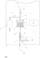
- a device 1 for the dispensing of a hot beverage comprises a hot water generating system 2 for the generation of hot water having a temperature of, e.g., 80 °C to 100 °C, and a brewing chamber 4.
- the brewing chamber has a hot water inlet 5 that can be fluidically connected to the hot water generating system 2 for the supply of hot water, as well as a hot beverage outlet 8 arranged on the bottom of the brewing chamber 4; the hot beverage brewed in the brewing chamber 4 can be dispensed from the outlet via a drain line 9.
- a brewing filter 7, which prevents the large particles of brewing material 6, e.g., coffee powders, from entering into the hot beverage outlet 8 and beyond this into the drain line 9 during the brewing process.
- the hot water inlet 5 is fluidically connected to the hot water generating system 2 via a T-shaped connection piece 17 and a first electrically switchable valve 11 on the inlet side.
- the hot beverage outlet 8, in contrast to this, is connected to the drain line 9 for the dispensing of the freshly brewed hot beverage into a vessel 40 via a Y-shaped connection piece 19 and a first electrically switchable pinch valve 13 on the outlet side.
- the hot beverage outlet 8 is connected to a compressed gas source 20 via an intermediately connected second electrically switchable shut-off valve 14 on the outlet side, this valve 14 being connected in the same way as are also the rest of the valves 11, 12 and 13 to an electronic control device 30, which controls them.
- the device 1 for the dispensing of a hot beverage comprises a second compressed gas source 21, which is connected to the T-shaped connection piece 17 by way of a second electrically switchable valve 12 on the inlet side, and can be utilized for the purpose of loading the brewing chamber 4 with compressed gas via the hot water inlet 5 toward the end of the brewing process.
- a second compressed gas source 21 which is connected to the T-shaped connection piece 17 by way of a second electrically switchable valve 12 on the inlet side, and can be utilized for the purpose of loading the brewing chamber 4 with compressed gas via the hot water inlet 5 toward the end of the brewing process.
- the electrically switchable shut-off valve 14 employed therein can be replaced by a non-return valve 16 arranged in the flow direction of the compressed gas from the compressed gas source 20, non-return or check valve 16 preventing a back flooding of the compressed gas source and, moreover, in an advantageous manner, it does not need to be actuated electrically.
- Figure 2 shows another embodiment of the device 1 according to the disclosure for the dispensing of a hot beverage, which is characterized in that one and the same compressed gas source 20 can be used for the purpose of loading the brewing chamber 4 with compressed gas both on the inlet side as 25 well as on the outlet side.
- the compressed gas source 20 can be connected to the hot beverage outlet 8 of the brewing chamber 4 via an electrically switchable first shut-off valve 15a during the brewing process by way of a compressed air line 10a, the first electrically switchable pinch valve 13 on the outlet side and the Y-shaped connection piece 19 on the outlet side.
- the first shut-off valve 15a is closed and a second shut-off valve 15b that can be actuated by the electronic control device 30 is opened, this latter valve preferably being disposed together with the first blockable shut-off valve 15a in a chain valve, or a chain of valves 15.
- the compressed air is introduced into the brewing chamber 4 in this case with a closed first valve 11 on the inlet side, i.e., with a closed-off hot water supply from the hot water generating system 2, by way of the T-shaped connection piece 17 and the hot water inlet 5 connecting thereto, so that the brewing chamber is loaded with a pressure of, e.g., 1 bar via the compressed air source 20.
- the pinch valve 13 is actuated and the connection line 10a is shut off by pressing together the elastically deformable tubing segment belonging thereto of the connection line 10a and freeing up the drain line 9, whereupon the freshly brewed hot beverage can flow through the brewing filter 7 into the vessel 40 by way of the hot beverage outlet 8 and the drain line 9.
- the second shut-off valve 15b can be closed, the drain line 9 can be opened by means of the pinch valve 13, and, via the first valve 11, hot water can be introduced into the brewing chamber 4, said hot water removing any residues of the hot beverage that adhere to the brewing chamber 4.
- this mode of operation can also be realized by a standard, closed 3/2 way valve that is disposed in the direction of flow of the compressed gas from the compressed gas source 20.
- the line 10a is also closed by means of a non-return valve 16, which is preferably spring-loaded, in order to prevent the possibility of pressing the brewing material into the compressed gas source 20.
- the single compressed gas source 20 in this case is connected to the hot water inlet 5 via a single shut-off valve 15b, and to the line 10a via the springloaded non-return valve 16; this line 10a can be shut off by the pinch valve 13 when, in conclusion to a brewing process, the hot beverage is expelled from the brewing chamber 4 by the compressed gas from the compressed gas source 20 via the drain line 9 after opening the single shut-off valve 15b.
Landscapes
- Engineering & Computer Science (AREA)
- Food Science & Technology (AREA)
- Mechanical Engineering (AREA)
- Apparatus For Making Beverages (AREA)
- Beverage Vending Machines With Cups, And Gas Or Electricity Vending Machines (AREA)
Claims (11)
- Verfahren zur Ausgabe eines Heißgetränks in einem Getränkeautomaten (1), der einen Heißwassererzeuger (2) zur Erzeugung von heißem Wasser und eine Brühkammer (4) umfasst, wobei die Brühkammer (4) zum Brühen eines Heißgetränks mit Brühgut (6) befüllt, und im Anschluss daran über einen Heißwassereinlass (5) mit Heißwasser beaufschlagt wird, und das Heißgetränk nach dem Brühvorgang über einen Heißgetränkeauslass (8) und eine damit verbundene Ablaufleitung (9) aus der Brühkammer (4) in ein Gefäß (40) abgeleitet wird, wobei der Heißgetränkeauslass (8) während eines Brühvorgangs mit Druckgas aus einer Druckgasquelle (20) beaufschlagbar ist,
dadurch gekennzeichnet, dass
das Druckgas Umgebungsluft ist und nach Beginn des Brühvorgangs mit einer einstellbaren Verzögerung in die Brühkammer (4) einleitbar ist. - Verfahren nach Anspruch 1,
dadurch gekennzeichnet, dass
die Dauer und die Stärke der Beaufschlagung der Brühkammer (4) mit Druckgas aus der Druckgasquelle (20) einstellbar ist. - Verfahren nach Anspruch 1,
dadurch gekennzeichnet, dass
die Brühkammer (4) zum Entleeren derselben nach einem Brühvorgang über den Heißwassereinlass (5) mit Druckgas der Druckgasquelle (20) oder einer weiteren Druckgasquelle (21) beaufschlagt wird. - Vorrichtung (4) zur Ausgabe eines Heißgetränkes in einem Getränkeautomaten (1), umfassend einen Heißwassererzeuger (20) zur Erzeugung von heißem Wasser und eine Brühkammer (4), welche einen mit dem Heißwassererzeuger (20) zur Zufuhr von Heißwasser strömungsmäßig verbindbaren Heißwassereinlass (5) sowie einen auf der Unterseite der Brühkammer (4) angeordneten Heißgetränkeauslass (8) zur Ausgabe eines in der Brühkammer (4) gebrühten Heißgetränks umfasst, wobei der Heißwassereinlass (5) über wenigstens ein Einlassventil (11) mit dem Heißwassererzeuger (2) strömungsmäßig verbindbar ist, und der Heißgetränkeauslass (8) über wenigstens ein auslassseitiges Ventil (13) mit einer Ablaufleitung (9) zur Ausgabe des Heißgetränks in ein Gefäß (40) verbindbar ist, wobei der Heißgetränkeauslass (8) über eine Abzweigleitung (10; 10a) und ein schaltbares weiteres auslassseitiges Ventil (13; 14; 15a; 18) während eines Brühvorgangs mit Druckgas aus einer Druckgasquelle (20; 21) beaufschlagbar ist, dadurch gekennzeichnet, dass
das Druckgas Umgebungsluft ist, und dass das schaltbare weitere auslassseitige Ventil (13; 14; 15a; 18) dazu eingerichtet ist, das Druckgas nach Beginn des Brühvorgangs mit einer einstellbaren Verzögerung in die Brühkammer (4) einzuleiten. - Vorrichtung nach Anspruch 4,
dadurch gekennzeichnet, dass
die Druckgasquelle (20; 21) eine elektrische Pumpe zum Fördern von Druckluft umfasst. - Vorrichtung nach Anspruch 4,
dadurch gekennzeichnet, dass
die Druckgasquelle (20; 21) einen Druckgasbehälter, insbesondere eine Druckgasflasche, umfasst. - Vorrichtung nach Anspruch 4,
dadurch gekennzeichnet, dass
der Heißgetränkeauslass (8) mit der Ablaufleitung (9) über einen flexibel deformierbaren Schlauch verbunden ist, und dass das wenigstens eine auslassseitige Ventil (13) ein Quetschventil ist, mittels welchem der Schlauch zum Verschließen desselben zusammenpressbar ist. - Vorrichtung nach Anspruch 4,
dadurch gekennzeichnet, dass
das wenigstens eine auslassseitige Ventil ein 3/2 Wegeventil (13) ist. - Vorrichtung nach Anspruch 4,
dadurch gekennzeichnet, dass
das schaltbare weitere auslassseitige Ventil ein Schaltventil (14) oder ein Kettenventil (15, 15a) oder ein 3/2 Wegeventil (18) umfasst, über welches die Druckluftquelle (20) über die Abzweigleitung (10a) mit dem Heißgetränkeauslass (8) verbindbar ist. - Vorrichtung nach Anspruch 9,
dadurch gekennzeichnet, dass
in der Abzweigleitung (10a) stromabwärts der Druckgasquelle (20) ein Rückschlagventil (16) angeordnet ist, welches die Druckgasquelle (20) gegen ein Eindringen von Brühgut (6) schützt. - Vorrichtung nach Anspruch 4,
dadurch gekennzeichnet, dass
die Druckgasquelle (20) über ein elektrisch schaltbares Absperrventil (15b) mit dem Heißwassereinlass (5) der Brühkammer (4) und über ein federbelastetes Rückschlagventil (16) mit der Abzweigleitung (10a) verbunden ist, wobei die Abzweigleitung (10a) einen flexibel deformierbaren Schlauch umfasst, und dass das schaltbare weitere auslassseitige Ventil ein Quetschventil (13) ist, mittels welchem der flexibel deformierbare Schlauch zum Verschließen desselben zusammenpressbar ist.
Applications Claiming Priority (2)
| Application Number | Priority Date | Filing Date | Title |
|---|---|---|---|
| DE102018007750.1A DE102018007750A1 (de) | 2018-10-02 | 2018-10-02 | Verfahren zur Ausgabe eines Heißgetränks |
| PCT/IB2019/001048 WO2020070551A1 (en) | 2018-10-02 | 2019-09-26 | Method for the dispensing of a hot beverage |
Publications (3)
| Publication Number | Publication Date |
|---|---|
| EP3860410A1 EP3860410A1 (de) | 2021-08-11 |
| EP3860410C0 EP3860410C0 (de) | 2025-06-18 |
| EP3860410B1 true EP3860410B1 (de) | 2025-06-18 |
Family
ID=68610254
Family Applications (1)
| Application Number | Title | Priority Date | Filing Date |
|---|---|---|---|
| EP19805730.9A Active EP3860410B1 (de) | 2018-10-02 | 2019-09-26 | Verfahren zur ausgabe eines heissgetränks |
Country Status (8)
| Country | Link |
|---|---|
| US (1) | US20210228016A1 (de) |
| EP (1) | EP3860410B1 (de) |
| JP (1) | JP2022502105A (de) |
| CN (1) | CN112788969A (de) |
| AU (1) | AU2019351930A1 (de) |
| CA (1) | CA3104426A1 (de) |
| DE (1) | DE102018007750A1 (de) |
| WO (1) | WO2020070551A1 (de) |
Families Citing this family (4)
| Publication number | Priority date | Publication date | Assignee | Title |
|---|---|---|---|---|
| PT3641601T (pt) * | 2017-06-22 | 2021-11-09 | Nestle Sa | Máquina de preparação de bebidas com bomba operada manualmente com meios de controlo de escoamento |
| CN116033855A (zh) * | 2020-08-27 | 2023-04-28 | 雀巢产品有限公司 | 卫生废物成分移除 |
| CN114504248B (zh) * | 2022-02-25 | 2025-07-18 | 深圳市西啡科技有限公司 | 一种饮料机 |
| NL2035905B1 (en) * | 2023-09-27 | 2025-04-08 | Douwe Egberts Bv | A method for preparing a coffee beverage from a container filled with an ingredient and a beverage brewing machine for preparing a coffee beverage from a container filled with an ingredient |
Family Cites Families (42)
| Publication number | Priority date | Publication date | Assignee | Title |
|---|---|---|---|---|
| WO1988002612A1 (en) * | 1986-10-18 | 1988-04-21 | Peter Andrew Carney | Apparatus for preparing an infusion |
| US4852621A (en) * | 1987-08-10 | 1989-08-01 | Bear Don E | Bottled water pressurization system |
| NL8901968A (nl) * | 1989-07-28 | 1991-02-18 | Jong J M Duke Automaten Bv De | Inrichting voor het door extractie bereiden van dranken zoals koffie of thee. |
| JP2976598B2 (ja) * | 1991-07-24 | 1999-11-10 | 富士電機株式会社 | 飲料抽出装置 |
| US5650186A (en) * | 1993-06-07 | 1997-07-22 | Annoni; Faust | Hot beverage brewing and dispensing apparatus and method |
| JPH07141562A (ja) * | 1993-11-16 | 1995-06-02 | Hoshizaki Electric Co Ltd | 冷凍炭酸飲料デイスペンサの運転開始方法 |
| NL1003716C2 (nl) * | 1996-07-31 | 1998-02-05 | Sara Lee De Nv | Werkwijze, systeem en inrichting voor het bereiden van een voor consumptie geschikte drank zoals koffie. |
| DE19855271C1 (de) | 1998-12-01 | 2000-09-07 | Spengler Getraenkemaschinen Gm | Brüheinrichtung (Monobrüher) zur Zubereitung von Kaffee oder Tee |
| US6298768B1 (en) * | 1998-12-28 | 2001-10-09 | Sanyo Electric Co., Ltd. | Beverage serving apparatus |
| US7021206B2 (en) * | 2002-06-18 | 2006-04-04 | Eckenhausen Roland B | Hot dairy-based beverage dispenser |
| US7225728B2 (en) * | 2004-01-30 | 2007-06-05 | Wilbur Curtis Company, Inc. | Brewing apparatus with pre-infusion and pulse brewing |
| EP1609398A1 (de) * | 2004-06-25 | 2005-12-28 | Nestec S.A. | Method for improving the production of steam during the preparation of drinks starting from a cartridge and device for carrying out the method |
| ATE392842T1 (de) * | 2004-11-04 | 2008-05-15 | Niro Plan Ag | Brühgruppe für eine kaffeemaschine |
| SI1827181T1 (sl) * | 2005-06-08 | 2008-10-31 | Massimo Crescenzi | Aparat za moka kavo in postopek za pripravo napitka z okusom kave |
| CN101355898B (zh) * | 2006-01-05 | 2010-12-15 | 布瑞威利私人有限公司 | 咖啡机的自动剂量控制 |
| EP1922963A1 (de) * | 2006-11-16 | 2008-05-21 | Petervin S.A. | Vorrichtung und Verfahren zur Extraktion eines Heissgetränks |
| JP5115097B2 (ja) * | 2006-12-15 | 2013-01-09 | 富士電機リテイルシステムズ株式会社 | 飲料抽出装置およびこれを備えた飲料供給装置 |
| AU2008266164A1 (en) * | 2007-06-11 | 2008-12-24 | Espressi Inc. | Portable brewing device and method of making and operating |
| ES2347366T3 (es) * | 2007-07-05 | 2010-10-28 | Schaerer Ag | Dispositivo para dispensar bebidas a base de leche. |
| US8286547B1 (en) * | 2008-05-23 | 2012-10-16 | Food Equipment Technologies Company, Inc. | Automated french press-like quality producing, high volume, automated, electric beverage maker |
| DE102009016506A1 (de) * | 2009-04-08 | 2010-10-14 | Melitta System Service Gmbh & Co Kg | Verfahren zum Erzeugen eines frischen kalten Kaffeegetränks und eine entsprechende Kaffeemaschine |
| DE102010007143B4 (de) * | 2010-02-05 | 2013-08-22 | Eugster/Frismag Ag | Kaffeemaschine mit einer Schäumvorrichtung und Mitteln zum Reinigen der Schäumvorrichtung und einer Milchansaugleitung sowie Verfahren zum Spülen der Milchansaugleitung |
| EP2592979B1 (de) * | 2010-07-14 | 2015-01-21 | Unilever N.V. | Getränkezubereitungsvorrichtung und -verfahren |
| EP3175744B1 (de) * | 2010-12-16 | 2023-11-29 | Briggo, LLC | Vorrichtung und verfahren für die herstellung von braugetränken und espressogetränken |
| AU2013308405B2 (en) * | 2012-08-30 | 2017-06-15 | Breville Pty Limited | Espresso machine with Americano feature |
| SMP201200046B1 (it) * | 2012-10-24 | 2015-07-09 | Caffemotive Srl | Un metodo per la produzione di una compressa di unprodotto macinato in polvere per l'estrazione di bevande nonchè compressa ottenibile con tale metodo |
| US8991795B2 (en) * | 2013-03-15 | 2015-03-31 | Briggo, Inc. | Frothing assembly and method of operating the same |
| EP3000362A1 (de) * | 2014-09-24 | 2016-03-30 | Qbo Coffee GmbH | Milchschäumergerät, Getränkezubereitungssystem und Getränkezubereitungsmaschine |
| CN107105919A (zh) * | 2014-10-06 | 2017-08-29 | 雷明顿设计有限责任公司 | 饮料冲泡系统及其使用方法 |
| CA2982166A1 (en) * | 2015-04-08 | 2016-10-13 | Bunn-O-Matic Corporation | Cold brew system, method and apparatus |
| MX395211B (es) * | 2015-09-17 | 2025-03-25 | Bunn O Matic Corp | Proceso de preparación de bebida. |
| US11744396B1 (en) * | 2015-11-10 | 2023-09-05 | Caffeine Innovations, LLC | System, method, and device for agitating coffee grounds |
| JP6875899B2 (ja) * | 2017-03-28 | 2021-05-26 | サンデン・リテールシステム株式会社 | 飲料供給装置 |
| JP6467615B1 (ja) * | 2017-08-07 | 2019-02-13 | 株式会社Tree Field | 飲料製造装置及び制御方法 |
| DK3536200T3 (da) * | 2017-08-07 | 2021-08-30 | Tree Field Inc | Ekstraktionsindretning og ekstraktionsfremgangsmåde |
| WO2019074951A1 (en) * | 2017-10-09 | 2019-04-18 | Altopa, Inc. | SECURED, ON-DEMAND PORTABLE MICROFLUIDIC DEVICE FOR MIXING AND DISPENSING MIXTURES OF LIQUIDS, SOLUTIONS, SUSPENSIONS, EMULSIONS AND COLLOIDS |
| SE544267C2 (en) * | 2018-05-18 | 2022-03-22 | Crem Int Aktiebolag | Device for the preparation of tea or coffee beverages and a corresponding method for preparing a beverage |
| NL2022190B1 (en) * | 2018-12-12 | 2020-07-03 | Douwe Egberts Bv | Air purge groove |
| US10932608B2 (en) * | 2019-01-24 | 2021-03-02 | Wen Pin Hsu | Air compressed coffee or tea making machine |
| DE202019104349U1 (de) * | 2019-08-07 | 2020-11-10 | Eversys Ag | Vorrichtung zum Erhitzen und Aufschäumen einer Flüssigkeit, insbesondere eines Getränks |
| CN116033855A (zh) * | 2020-08-27 | 2023-04-28 | 雀巢产品有限公司 | 卫生废物成分移除 |
| JP7112131B1 (ja) * | 2021-03-19 | 2022-08-03 | 株式会社大都技研 | コーヒーマシン |
-
2018
- 2018-10-02 DE DE102018007750.1A patent/DE102018007750A1/de active Pending
-
2019
- 2019-09-26 WO PCT/IB2019/001048 patent/WO2020070551A1/en not_active Ceased
- 2019-09-26 CA CA3104426A patent/CA3104426A1/en active Pending
- 2019-09-26 CN CN201980064998.2A patent/CN112788969A/zh active Pending
- 2019-09-26 US US17/252,838 patent/US20210228016A1/en not_active Abandoned
- 2019-09-26 JP JP2021510233A patent/JP2022502105A/ja active Pending
- 2019-09-26 EP EP19805730.9A patent/EP3860410B1/de active Active
- 2019-09-26 AU AU2019351930A patent/AU2019351930A1/en not_active Abandoned
Also Published As
| Publication number | Publication date |
|---|---|
| DE102018007750A1 (de) | 2020-04-02 |
| AU2019351930A1 (en) | 2021-02-25 |
| JP2022502105A (ja) | 2022-01-11 |
| US20210228016A1 (en) | 2021-07-29 |
| WO2020070551A1 (en) | 2020-04-09 |
| CA3104426A1 (en) | 2020-04-09 |
| EP3860410A1 (de) | 2021-08-11 |
| CN112788969A (zh) | 2021-05-11 |
| EP3860410C0 (de) | 2025-06-18 |
Similar Documents
| Publication | Publication Date | Title |
|---|---|---|
| EP3860410B1 (de) | Verfahren zur ausgabe eines heissgetränks | |
| US10610048B2 (en) | Beverage preparation machine | |
| CN102083345B (zh) | 气压可控制的饮料制造设备、系统和方法 | |
| CA2578417C (en) | Liquid dispensing apparatus | |
| EP3687345B1 (de) | Automatische kaffeemaschine und verfahren zur herstellung eines kaltgebrauten getränks | |
| WO2008058731A2 (en) | Apparatus and method for extracting a hot beverage | |
| US20240415320A1 (en) | Initial discharge of cold water in a preheating process of a beverage making device | |
| US20240206673A1 (en) | Device for preparing a coffee beverage | |
| US20240415322A1 (en) | Discharge of rinsing water from a brew chamber of a beverage making device | |
| EP3733032A1 (de) | Automatische kaffeemaschine | |
| RU2849513C2 (ru) | Устройство для приготовления кофейного напитка | |
| CN117136024B (zh) | 用于制备咖啡饮料的装置 | |
| JPH10334340A (ja) | 飲料供給装置 | |
| JPH07272118A (ja) | 抽出濾過装置 |
Legal Events
| Date | Code | Title | Description |
|---|---|---|---|
| STAA | Information on the status of an ep patent application or granted ep patent |
Free format text: STATUS: UNKNOWN |
|
| STAA | Information on the status of an ep patent application or granted ep patent |
Free format text: STATUS: THE INTERNATIONAL PUBLICATION HAS BEEN MADE |
|
| PUAI | Public reference made under article 153(3) epc to a published international application that has entered the european phase |
Free format text: ORIGINAL CODE: 0009012 |
|
| STAA | Information on the status of an ep patent application or granted ep patent |
Free format text: STATUS: REQUEST FOR EXAMINATION WAS MADE |
|
| 17P | Request for examination filed |
Effective date: 20210503 |
|
| AK | Designated contracting states |
Kind code of ref document: A1 Designated state(s): AL AT BE BG CH CY CZ DE DK EE ES FI FR GB GR HR HU IE IS IT LI LT LU LV MC MK MT NL NO PL PT RO RS SE SI SK SM TR |
|
| DAV | Request for validation of the european patent (deleted) | ||
| DAX | Request for extension of the european patent (deleted) | ||
| STAA | Information on the status of an ep patent application or granted ep patent |
Free format text: STATUS: EXAMINATION IS IN PROGRESS |
|
| 17Q | First examination report despatched |
Effective date: 20230929 |
|
| GRAP | Despatch of communication of intention to grant a patent |
Free format text: ORIGINAL CODE: EPIDOSNIGR1 |
|
| STAA | Information on the status of an ep patent application or granted ep patent |
Free format text: STATUS: GRANT OF PATENT IS INTENDED |
|
| INTG | Intention to grant announced |
Effective date: 20250407 |
|
| GRAS | Grant fee paid |
Free format text: ORIGINAL CODE: EPIDOSNIGR3 |
|
| GRAA | (expected) grant |
Free format text: ORIGINAL CODE: 0009210 |
|
| STAA | Information on the status of an ep patent application or granted ep patent |
Free format text: STATUS: THE PATENT HAS BEEN GRANTED |
|
| AK | Designated contracting states |
Kind code of ref document: B1 Designated state(s): AL AT BE BG CH CY CZ DE DK EE ES FI FR GB GR HR HU IE IS IT LI LT LU LV MC MK MT NL NO PL PT RO RS SE SI SK SM TR |
|
| REG | Reference to a national code |
Ref country code: GB Ref legal event code: FG4D |
|
| REG | Reference to a national code |
Ref country code: CH Ref legal event code: EP |
|
| REG | Reference to a national code |
Ref country code: CH Ref legal event code: EP |
|
| REG | Reference to a national code |
Ref country code: IE Ref legal event code: FG4D |
|
| U01 | Request for unitary effect filed |
Effective date: 20250623 |
|
| U07 | Unitary effect registered |
Designated state(s): AT BE BG DE DK EE FI FR IT LT LU LV MT NL PT RO SE SI Effective date: 20250701 |
|
| PG25 | Lapsed in a contracting state [announced via postgrant information from national office to epo] |
Ref country code: GR Free format text: LAPSE BECAUSE OF FAILURE TO SUBMIT A TRANSLATION OF THE DESCRIPTION OR TO PAY THE FEE WITHIN THE PRESCRIBED TIME-LIMIT Effective date: 20250919 |
|
| PGFP | Annual fee paid to national office [announced via postgrant information from national office to epo] |
Ref country code: NO Payment date: 20250919 Year of fee payment: 7 |
|
| PG25 | Lapsed in a contracting state [announced via postgrant information from national office to epo] |
Ref country code: HR Free format text: LAPSE BECAUSE OF FAILURE TO SUBMIT A TRANSLATION OF THE DESCRIPTION OR TO PAY THE FEE WITHIN THE PRESCRIBED TIME-LIMIT Effective date: 20250618 |
|
| PG25 | Lapsed in a contracting state [announced via postgrant information from national office to epo] |
Ref country code: RS Free format text: LAPSE BECAUSE OF FAILURE TO SUBMIT A TRANSLATION OF THE DESCRIPTION OR TO PAY THE FEE WITHIN THE PRESCRIBED TIME-LIMIT Effective date: 20250918 |
|
| U20 | Renewal fee for the european patent with unitary effect paid |
Year of fee payment: 7 Effective date: 20250923 |
|
| PG25 | Lapsed in a contracting state [announced via postgrant information from national office to epo] |
Ref country code: IS Free format text: LAPSE BECAUSE OF FAILURE TO SUBMIT A TRANSLATION OF THE DESCRIPTION OR TO PAY THE FEE WITHIN THE PRESCRIBED TIME-LIMIT Effective date: 20251018 |
|
| PGFP | Annual fee paid to national office [announced via postgrant information from national office to epo] |
Ref country code: GB Payment date: 20251113 Year of fee payment: 7 |
|
| PG25 | Lapsed in a contracting state [announced via postgrant information from national office to epo] |
Ref country code: SM Free format text: LAPSE BECAUSE OF FAILURE TO SUBMIT A TRANSLATION OF THE DESCRIPTION OR TO PAY THE FEE WITHIN THE PRESCRIBED TIME-LIMIT Effective date: 20250618 |
|
| PG25 | Lapsed in a contracting state [announced via postgrant information from national office to epo] |
Ref country code: CZ Free format text: LAPSE BECAUSE OF FAILURE TO SUBMIT A TRANSLATION OF THE DESCRIPTION OR TO PAY THE FEE WITHIN THE PRESCRIBED TIME-LIMIT Effective date: 20250618 |
|
| PG25 | Lapsed in a contracting state [announced via postgrant information from national office to epo] |
Ref country code: PL Free format text: LAPSE BECAUSE OF FAILURE TO SUBMIT A TRANSLATION OF THE DESCRIPTION OR TO PAY THE FEE WITHIN THE PRESCRIBED TIME-LIMIT Effective date: 20250618 |
|
| PG25 | Lapsed in a contracting state [announced via postgrant information from national office to epo] |
Ref country code: SK Free format text: LAPSE BECAUSE OF FAILURE TO SUBMIT A TRANSLATION OF THE DESCRIPTION OR TO PAY THE FEE WITHIN THE PRESCRIBED TIME-LIMIT Effective date: 20250618 |
|
| PG25 | Lapsed in a contracting state [announced via postgrant information from national office to epo] |
Ref country code: ES Free format text: LAPSE BECAUSE OF FAILURE TO SUBMIT A TRANSLATION OF THE DESCRIPTION OR TO PAY THE FEE WITHIN THE PRESCRIBED TIME-LIMIT Effective date: 20250618 |