EP3859297A1 - Dispositif d'essai pour transmissions, procédure d'essai, unité de commande et produit programme informatique - Google Patents
Dispositif d'essai pour transmissions, procédure d'essai, unité de commande et produit programme informatique Download PDFInfo
- Publication number
- EP3859297A1 EP3859297A1 EP20154842.7A EP20154842A EP3859297A1 EP 3859297 A1 EP3859297 A1 EP 3859297A1 EP 20154842 A EP20154842 A EP 20154842A EP 3859297 A1 EP3859297 A1 EP 3859297A1
- Authority
- EP
- European Patent Office
- Prior art keywords
- testing device
- gear
- designed
- test
- control unit
- Prior art date
- Legal status (The legal status is an assumption and is not a legal conclusion. Google has not performed a legal analysis and makes no representation as to the accuracy of the status listed.)
- Pending
Links
Images


Classifications
-
- G—PHYSICS
- G01—MEASURING; TESTING
- G01M—TESTING STATIC OR DYNAMIC BALANCE OF MACHINES OR STRUCTURES; TESTING OF STRUCTURES OR APPARATUS, NOT OTHERWISE PROVIDED FOR
- G01M13/00—Testing of machine parts
- G01M13/02—Gearings; Transmission mechanisms
- G01M13/021—Gearings
-
- G—PHYSICS
- G01—MEASURING; TESTING
- G01M—TESTING STATIC OR DYNAMIC BALANCE OF MACHINES OR STRUCTURES; TESTING OF STRUCTURES OR APPARATUS, NOT OTHERWISE PROVIDED FOR
- G01M13/00—Testing of machine parts
- G01M13/02—Gearings; Transmission mechanisms
- G01M13/022—Power-transmitting couplings or clutches
-
- G—PHYSICS
- G01—MEASURING; TESTING
- G01M—TESTING STATIC OR DYNAMIC BALANCE OF MACHINES OR STRUCTURES; TESTING OF STRUCTURES OR APPARATUS, NOT OTHERWISE PROVIDED FOR
- G01M13/00—Testing of machine parts
- G01M13/02—Gearings; Transmission mechanisms
- G01M13/025—Test-benches with rotational drive means and loading means; Load or drive simulation
-
- Y—GENERAL TAGGING OF NEW TECHNOLOGICAL DEVELOPMENTS; GENERAL TAGGING OF CROSS-SECTIONAL TECHNOLOGIES SPANNING OVER SEVERAL SECTIONS OF THE IPC; TECHNICAL SUBJECTS COVERED BY FORMER USPC CROSS-REFERENCE ART COLLECTIONS [XRACs] AND DIGESTS
- Y02—TECHNOLOGIES OR APPLICATIONS FOR MITIGATION OR ADAPTATION AGAINST CLIMATE CHANGE
- Y02E—REDUCTION OF GREENHOUSE GAS [GHG] EMISSIONS, RELATED TO ENERGY GENERATION, TRANSMISSION OR DISTRIBUTION
- Y02E10/00—Energy generation through renewable energy sources
- Y02E10/70—Wind energy
- Y02E10/72—Wind turbines with rotation axis in wind direction
Definitions
- the invention relates to a testing device for transmissions and a corresponding testing method.
- the invention also relates to a control unit which is designed to carry out the testing method according to the invention on such a testing device.
- the invention also relates to a computer program product which can be stored and executed on the control unit in order to carry out the testing method.
- test stands are designed for maximum drive powers of 7.5 MW and 15 MW.
- At least one drive motor which is connected to a countershaft transmission via a high-speed shaft, is arranged on each of the test stands.
- a low-speed shaft emerges from the countershaft transmission, via which a rotor of a wind turbine nacelle to be tested is driven.
- the rotor of the wind turbine nacelle is connected by means of an essentially toroidal load introduction unit which is suitable for simulating operating states of the wind turbine.
- a wind power transmission test bench is known on which two transmissions can be mounted.
- the gears are driven by a drive unit that is connected to a load unit by means of a torsion bar.
- the load unit is connected to two torsion bars that can be braced against each other.
- the document EP 2 574 778 B1 shows a testing device for a transmission and an electromechanical energy converter, in which the transmission to be tested is mounted in a transmission system.
- the transmission to be tested is supplied with drive power via several motors, which is also fed into the electromechanical energy converter.
- High-performance transmissions are used in various areas of application, the development process or approval process of which requires the corresponding transmission to be tested. There is therefore a need for a test device for transmissions which allows test runs to be carried out quickly, offers a high degree of flexibility and can be produced in a simple manner.
- the invention is based on the object of providing a possibility for testing transmissions which offers an improvement in at least one of the outlined aspects.
- the object is achieved by the testing device according to the invention for transmissions, which comprises a drive unit and an output unit.
- the drive unit provides a mechanical drive power with which the gearboxes to be tested can be driven.
- the drive unit can be designed as an electric motor, for example.
- the output unit is designed to absorb the mechanical drive power passed through the gearbox.
- the output unit can be designed, for example, as a generator or as a brake.
- the drive unit and the output unit are to be tested with the testing device via a first and a second transmission are connected to each other.
- the connection via the first and second gear transmits the mechanical drive power from the drive unit to the output unit.
- the rotational speeds present in the first and second transmission can be specified as part of a test run.
- the first gear is designed to be tiltable and / or displaceable in an adjustable manner.
- the testing device is accordingly designed to tilt and / or shift at least the first transmission adjustably when the first transmission is connected to the testing device as intended.
- Tilting takes place around at least one spatial axis, which can be aligned perpendicular to a main axis of rotation of the first gear or coincides with the main axis of rotation of the first gear.
- the shifting takes place translationally along at least one of the spatial axes. Tilting and / or shifting also causes a mechanical reaction on the second gear. The first transmission and the second transmission can thereby be tested at least partially at the same time.
- first and second gears can be of different types, that is, not structurally identical or mutually interchangeable.
- the difference in type is also to be understood as the case of a first and second gearbox that have different components at certain points. This can be, for example, gears with different bearings, but otherwise the same structure.
- transmissions can also be tested at least partially at the same time, in which components are manufactured in different manufacturing processes, but otherwise have the same structure. This allows different types, models or variants of transmissions to be tested in a joint test run, which reduces the number of test runs required, for example for a test program. The number of required As a result, test runs can essentially be halved, which overall allows economical test runs.
- a mechanical reaction can be generated by tilting and / or shifting the first gear between the first and second gear.
- the mechanical reaction can include a reaction force and / or a reaction torque.
- real operation of the transmission can be reproduced, in which the mechanical drive power is introduced with a deviation from an idealized main axis of rotation.
- a real operating state with changing wind conditions can be simulated, particularly in the case of gearboxes that are to be used in wind power plants.
- the mechanical reaction which comprises the reaction force and / or the reaction torque, can thus be specifically specified and is suitable for being part of a test run as an operating condition specification that is to be carried out with the test device.
- this allows a wide range of programs to be specified for testing the transmission, for example by a user, an algorithm or a table.
- Such a link ensures in a simple manner that the two transmissions can be compared under corresponding operating conditions. This can also shorten the overall duration required for a test program.
- the second transmission can also be designed to be tiltable and / or displaceable.
- the tiltability or displaceability of the second gear can correspond to the tiltability of the first gear.
- the testing device is also designed to tilt and / or move the second gear in an adjustable manner.
- the tiltability and / or displaceability of the second gear make it possible during a test run cause a wider range of stresses and thus reaction forces and / or reaction torques.
- the first and second gears can be tilted and / or shifted at the same time, and thereby a deflection to be set can be divided into several tilting and / or shifting movements. This further increases the flexibility of the claimed testing device.
- the claimed testing device has at least one actuator which is designed to tilt and / or move at least the first transmission.
- the actuator can be firmly connected to the environment, for example.
- the actuator can also be arranged between the first and second gears and / or be designed as a rotating actuator.
- the actuator can be designed as a hydraulic cylinder, servo motor and / or spindle drive.
- Actuators, especially hydraulic cylinders are available in different designs that offer a high actuation force with high actuation precision at the same time.
- reached operating positions of the actuator can be precisely held.
- the tilting and / or shifting can be carried out exactly in the test run, which in turn leads to precise measurement data.
- the first transmission can be tilted and / or displaced via a plurality of actuators, as a result of which the outlined advantages are achieved to a greater extent.
- the second transmission can also be designed to be tiltable and / or displaceable via at least one actuator. In this way, too, the described advantages of a precise execution of a test run are achieved to a greater extent.
- Actuators such as hydraulic cylinders are also available in a large number of sizes. A technically complex toroidal or crown-shaped load application unit is not necessary in the claimed test unit. Such actuators can also be repaired in a simple manner, which allows particularly cost-efficient maintenance. This offers the claimed solution has a particularly high level of economy overall.
- the first transmission in the claimed testing device can be arranged on a tiltable support frame.
- a support frame can for example be arranged on articulated supports and / or at least one actuator. The spatial position of the support frame can be changed by actuating the at least one actuator.
- the first gearbox can be attached to a test bracket on the support frame.
- the second transmission can also be arranged on such a support frame.
- the use of support frames offers an overall uniform test setup on the claimed testing device, which is suitable for a large number of different types of gearboxes and allows a simplified sequence of test runs.
- the first and second gears are connected to one another in opposite transmission directions.
- Such an arrangement is also called a back-to-back arrangement.
- the present speed is first increased in a transmission and then the present speed is reduced.
- an arrangement of the first and second gear units that is reversed in terms of increase and reduction is also possible.
- the drive output unit is supplied with the mechanical drive power at a speed that is similarly high or identical or different than when it exits the drive unit.
- the drive unit and the output unit for example an electric motor and a generator, can thus be designed, for example, as electromechanical machines of the same construction and operating in opposite directions.
- the at least one actuator can be attached to the ground. This ensures a stable connection with the environment, which in turn allows long-term, precise execution of test runs.
- the at least one actuator can be arranged below the at least first transmission.
- a plurality of actuators can be arranged on a foundation that is received below a floor level.
- the floor level is to be understood here as a floor level in the surroundings, for example a hall floor.
- the foundation can accordingly be located essentially in a basement-like depression.
- the at least one actuator is arranged at least partially below the floor level.
- the actuators can thus be positioned on a reduced foundation area, which in turn requires less construction effort.
- the testing device has a reduced vertical dimension.
- the testing device can be set up in a low hall, which also allows a lower crane runway in the hall.
- the claimed testing device also offers improved accessibility, which enables simplified maintenance.
- a foundation can be used in conjunction with the ground level one wall serve as a tub. Such a tub prevents hydraulic fluid from penetrating into the environment in the event of a leak, for example.
- the claimed test arrangement is thus space-saving, can be manufactured and maintained in a cost-efficient manner, and offers a high level of security against environmental damage.
- the first or second transmission can be connected to the drive unit or the output unit in a direct torque-transmitting manner.
- the mechanical drive power generated by the drive unit is fed to the first or second transmission without changing the present speed or the present torque.
- a countershaft transmission or a so-called direct drive unit can therefore be dispensed with in the claimed testing device. This also further increases the advantages of the claimed testing device outlined above.
- the first and / or second gearbox can be designed as a wind turbine gearbox.
- different wind conditions must be tested in test runs, for example changing wind directions and wind strengths.
- the mechanical drive power must be fed into the gearbox in a manner deviating from an idealized main axis of rotation.
- the mechanical drive power is to be subjected to a radial transverse force which acts on an input shaft of the corresponding transmission.
- a radial transverse force can arise through wind loads on a rotor of a wind power plant, which in turn act on a rotor shaft that is connected to the input shaft of the transmission.
- the claimed testing device offers a simple one and economical possibility of generating corresponding reaction forces and / or reaction torques by tilting and / or shifting the at least first gear, which adjust such wind conditions.
- the technical advantages of the claimed testing device can be achieved to a particular extent if a wind turbine gearbox is tested with it.
- a wide range of conditions of use of transmissions for industrial applications can be reproduced by means of the claimed testing device.
- the claimed testing device can also be assigned a control unit which is designed to tilt at least the first transmission.
- the control unit is set up to output control commands to components of the testing device, for example to actuators, and thus to generate the reaction forces and / or reaction torques through which an operating condition specification is implemented at least on the first transmission. In this way, for example, changing wind conditions can be reproduced.
- reaction forces and / or reaction torques can be specified in a simple manner in relation to several spatial axes.
- the control unit can be designed to control further components of the testing device, for example by specifying a speed of the drive unit. In the same way, further parameters, such as pressures, temperatures or speeds, which can be relevant for a test run, can be set by means of the control unit.
- the control unit can be assigned directly to the testing device, for example as an internal control unit.
- the control unit can also be designed as a higher-level control unit which is coupled to the testing device via a data connection.
- the control unit can also be used as a combination of an internal and a be designed higher-level control unit.
- a control unit allows a user to set an operating condition specification for a test run in a simple manner, for example by means of a user input, an algorithm or a table which reproduce a desired test run. Such control units thus give the claimed testing device improved user friendliness and a high degree of flexibility in operation.
- the claimed testing device can be provided with a central bearing through which the first and second gears can be connected to one another.
- the first and second gears are arranged on opposite sides of the center bearing and are detachably connected to it.
- the center bearing is designed to absorb radial forces that act on at least one shaft that connects the first and second gears in a torque-transmitting manner.
- the central bearing can be directly connected to the environment, that is to say the subsurface or a foundation.
- the central bearing can also be connected to the environment via an actuator.
- the central bearing is used to introduce the absorbed radial forces into the environment.
- the actuator can also be used to exert a test force on the center bearing, and thus also on the first and second gears. This allows complex dynamic operating conditions, for example changing wind conditions, to be simulated in a variety of ways.
- the task described is also achieved by a method according to the invention for testing transmissions.
- the method according to the invention comprises a first step in which a first and a second transmission are provided in a testing device.
- a drive unit that is assigned to the testing device is activated.
- mechanical drive power is thus provided for the first and second transmission the operation of the transmission occurs, which is to be recorded as part of the testing.
- a loading torque is provided by the output unit.
- an adjustable tilting and / or shifting of at least the first gear takes place. As a result, a reaction force and / or a reaction torque is produced between the first transmission and the second transmission.
- the reaction force and / or the reaction torque correspond to a test force or a test torque. If there is a central bearing, also in the form of a radial force.
- the test force (s) or the test torque (s) belong to an operating condition specification that is part of an intended test run. In this way, for example, variable wind conditions on a wind turbine, and thus the variable operating conditions of a wind turbine gearbox, can be adjusted.
- measurement data can be recorded on the first and / or second gearbox by means of at least one sensor, which describes a load condition of the gearbox that is to be detected.
- the testing of the first and second transmission can take place at least partially at the same time.
- the mechanical reactions which include the reaction force and / or the reaction torque, are essentially the same (mirror image) for the first and second transmission, so that the same operating conditions exist for both transmissions at least partially simultaneously in the same test run.
- This makes it possible, for example by means of time stamps, to directly compare measurement data relating to the first transmission with measurement data relating to the second transmission.
- the first and second gears can be of different types.
- the claimed method offers increased efficiency, since, compared to known solutions, two types of transmissions of different types can now be tested at once. Alternatively, two identical gearboxes can be used be tested at the same time.
- the claimed method can be carried out by means of a testing device according to one of the embodiments outlined above.
- the described testing devices allow the claimed method to be carried out quickly and economically in a particularly simple, low-maintenance and precise manner.
- the task outlined above is also achieved by a control unit according to the invention.
- the control unit comprises a memory and an arithmetic unit and is suitable for receiving user inputs and outputting control commands to at least one actuator of a testing device.
- the control unit can be assigned directly to the testing device as an internal control unit, or it can be designed as a superordinate control unit which is coupled to the testing device via a data connection.
- An internal control unit can be designed, for example, as a programmable logic controller, or PLC for short, or also a programmable logic controller, or PLC for short.
- a higher-level control unit can be designed, for example, as a host computer, web server, handheld device or computer cloud.
- control unit can also be designed as a combination of an internal control unit and a higher-level control unit.
- control unit is designed to carry out a method according to at least one of the embodiments described above.
- a computer program product can be stored in an executable manner in the control unit.
- control unit according to the invention can be equipped with a testing device be connected according to one of the embodiments outlined above.
- the task described is also achieved by a computer program product according to the invention.
- the computer program product is designed to specify and set test forces and / or test torques for testing transmissions in a test run.
- the computer program product is designed to output control commands to at least one actuator that belongs to a testing device.
- the computer program product can be designed as software, in the form of a chip, that is to say hard-wired, or an FPGA circuit, or a combination thereof.
- the computer program product can be designed monolithically, or as a system of at least two partial programs that can be executed on separate hardware and that implement the functionality of the computer program product in communication with one another.
- the computer program product is designed to be executed on a control unit according to the invention.
- a testing device in cooperation with a control unit, a testing device according to one of the embodiments described above can be operated or one of the methods presented above can be implemented.
- the computer program product according to the invention offers the possibility of testing two transmissions together in a simple manner and offers a high degree of configurability.
- desired operating condition specifications can be set by a user input, which can be automatically converted into corresponding reaction forces and / or reaction torques by the computer program product.
- the claimed testing device can also be regulated during operation by the claimed computer program product.
- the computer program product can also be designed to store and evaluate received measurement data from at least one sensor that is attached to the first or second transmission.
- simulation image of the first and / or second transmission, and / or a wind turbine and / or an industrial application are also known as digital twins.
- the operation and use of a corresponding testing device is thus simplified and the testing operation is accelerated.
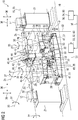
- FIG 1 a first embodiment of a claimed testing device 10 is shown schematically in a sectional view.
- the testing device 10 comprises a drive unit 12, which is designed as an electric motor, and an output unit 14, which is designed as a generator.
- the drive unit 12 and the output unit 14 are each arranged on a base 21.
- Between the Drive unit 12 and output unit 14 have a first and a second gear 20, 30, which are designed as wind turbine gearboxes 47.
- the first and second gears 20, 30 are of different types and are to be tested on the testing device 10.
- a mechanical drive power 25 can be provided by the drive unit 12, which is delivered to the output unit 14 by the first and second gears 20, 30.
- the drive power 25 is generated around a main axis of rotation 15 of the first and second gears 20, 30, which in connection with the testing device 10 represents a spatial axis 35.
- the operation of the drive unit 12 can at least be supported by generating electricity with the output unit 14 designed as a generator.
- the drive unit 12 is directly connected to the first gear 20 on its output side 29 in a torque-transmitting manner via a power shaft 32.
- the second gear 30 is directly connected to the output unit 14 on its output side 29 via a power shaft 32 in a torque-transmitting manner.
- the first and second gears 20, 30 are connected to one another via a center bearing 34.
- the center bearing 34 is designed to connect shafts of the first and second gears 20, 30 in a torque-transmitting manner and to absorb radial forces in relation to the main axis of rotation 15.
- the center bearing 34 is also connected to the surroundings, that is to say the floor level 16, via an actuator. Radial forces can be introduced into the first and second gears 20, 30 by the actuator 22.
- a flow of mechanical drive power 25 which in FIG 1 is shown as an arrow, there is a reduction in a speed in the first gear 20 and an increase in a speed in the second gear.
- the first and second gears 20, 30 are each connected with their drive side 26 to the connecting flange 34, and thus in the opposite transmission direction, that is, the direction of the speed change.
- the first and second gear 20, 30 are each attached to a test bracket 24, each with a support frame 18 is connected, which is located at a ground level 16 substantially at ground level.
- the support frame 18 is designed to be tiltable and / or displaceable, so that a mechanical reaction 40 can be brought about in a targeted manner in the area of the central bearing 34.
- the support frames 18 are each fastened to actuators 22, which are designed as hydraulic cylinders.
- the actuators 22 are each designed to exert an actuator force 33 and thus to cause tilting 27 and / or displacement 36 of the first and / or second transmission 20, 30.
- Such a tilting 27 and / or shifting 36 can take place around a plurality of spatial axes 35, as in FIG FIG 1 shown.
- the mechanical reaction 40 includes, depending on the orientation of the tilting 27 or displacement 36, reaction forces 42 in the area of the central bearing 34, which are oriented in different spatial directions. Corresponding to this, the mechanical reaction 40 also includes reaction torques 44 which have different orientations according to the reaction forces 42. Actuation of the actuators 22 is adjustable, so that tilting 27 and / or shifting 36 of the first and / or second gear 20, 30 can be brought about in a targeted manner. The mechanical reaction 40 that is brought about corresponds to a desired operating state of the first and second gear 20, 30 under which they are to be tested. Accordingly, there are reaction forces 42 and / or reaction torques 44 in the first and second gears 20, 30.
- the actuators 22 are arranged on a foundation 17 which lies below the ground level 16.
- the foundation 17 serves as the base 19 and lies below the support frame 18 with the test brackets 24 for the gears 20, 30.
- the actuators 22 are thereby positioned essentially in a basement-like depression.
- the actuators 22 can be positioned close to one another, as a result of which the foundation 17 has a reduced size.
- Sufficiently resilient foundations 17 and also sufficiently resilient bases 21 are complex and costly.
- the testing device 10 requires smaller foundations 17 and base 21 than solutions known from the prior art and can therefore be manufactured with reduced construction costs.
- FIG 2 shows schematically a second embodiment of the claimed testing device 10 in a partially sectioned oblique view.
- the testing device 10 comprises a drive unit 12 and an output unit 14, which are connected to one another in a torque-transmitting manner via a first and a second transmission 20, 30.
- the gears 20, 30 are designed as wind turbine gears 47 and are of different types.
- the first and second transmissions 20, 30 are to be tested in the testing device 10 at least partially at the same time.
- the drive unit 12 is arranged on a base 21 and is designed as an electric motor, by means of which mechanical drive power 25 is provided.
- the mechanical drive power 25, the direction of flow of which is shown by the arrow 25, is transmitted directly to an output side 29 of the first gear 20 via a power shaft 32.
- the mechanical drive power 25 has a torque which is oriented around a main axis of rotation 15 of the gears 20, 30 and, in connection with the testing device 10, corresponds to a spatial axis 35.
- the first and second gears 20, 30 are connected to the center bearing 34 via their respective drive sides 26. In the first gear 20 there is an increase in the speed and in the second gear 30 there is a reduction in the speed Rotational speed.
- the first and second gears 20, 30 are thus connected to one another in opposite transmission directions. This arrangement is also called a back-to-back arrangement.
- the second transmission 30 is also directly connected on its output side 29 via a power shaft 32 to the output unit 14, which is designed as a generator.
- the drive unit 12 can at least partially be operated with the electrical energy obtained in the output unit 14.
- the output unit 14 is also positioned on a base 21, corresponding to the drive unit 12.
- the gears 20, 30 are attached to test brackets 24 which are each arranged on a support frame 18.
- the support frames 18, in turn, are movably received on a plurality of actuators 22 and supports 28.
- the actuators 22, which are designed as hydraulic cylinders, are suitable for exerting an actuator force 33 by means of which the support frames 18 can be tilted and / or displaced.
- the actuators 22 are arranged on a base frame 39, which serves as a base 19 for the actuators 22.
- a tilting 27 and / or displacement 36 of the first and / or second gear 20, 30 about or along a spatial axis 35 can thus be brought about by a corresponding actuation of the actuators 22.
- a mirror-inverted mechanical reaction 40 is produced in the first and second gears 20, 30, each of which comprises reaction forces 42 and reaction torques 44.
- the reaction forces 42 and reaction torques 44 in the first and in the second gear 20, 30 are thus essentially the same in mirror image at the same time.
- the first and second gears are therefore subjected to the same mechanical stress at the same time.
- the corresponding states that are present at the same time therefore make it possible to compare the testing of the first transmission directly with the testing of the second transmission.
- the test facility as a whole and each of the gears 20, 30 are equipped with sensors 45, which are not shown in detail Measuring points 51 are arranged in the respective transmission 20, 30.
- the sensors 45 are designed to transmit measurement data 53 to a control unit 50.
- the control unit 50 comprises an internal control unit 52 which is assigned directly to the testing device 10.
- the control unit 50 is also designed to output control commands 55 to at least one of the actuators 22.
- the control unit 50 also comprises a higher-level control unit 54, which is connected to the internal control unit 52 via a data connection 56.
- the higher-level control unit 54 can be designed, for example, as a computer cloud or master computer, which interacts with the internal control unit 52 for trial operation.
- the internal control unit 52 and the superordinate control unit 54 each have a memory for storing and executing a computer program product 60 via which the testing device 10 can be operated.
- the computer program product 60 can be used to specify control commands 55 for the actuators 22 and / or measurement data 53 can be stored and / or processed by the sensors 45.
- FIG 3 a third embodiment of the claimed testing device 10 is shown schematically.
- the testing device 10 comprises a drive unit 12 and an output unit 14.
- the drive unit 12, which is designed as an electric motor, provides a mechanical drive power 25 which is fed to a first gear 20 via a power shaft 32.
- the first gear 20 is connected via a central bearing 34 to a second gear 30, via which the mechanical drive power 25 is directly fed to the output unit 14, which is designed as a generator, by means of a power shaft 32.
- the center bearing 34 is connected to the floor level 16 via at least one actuator 22 or via a passive connection.
- the first and second gears 20, 30 are each designed as wind turbine gears 47.
- the Mechanical drive power 25 is transported in the testing device 10 in the sketched direction of the arrow along a main axis of rotation 15 of the gears 20, 30, which is to be understood as the spatial axis 35 in the testing device 10.
- the drive unit 12 and the output unit 14 are each positioned on a base 21, which stand on a floor level 16.
- the gears 20, 30 arranged in between are each fastened in a test holder 24, which can be tilted and displaced along or around a plurality of spatial axes 35.
- the test holder 24 is permanently connected to a support frame 18, which can be tilted with the test holder 24 about a joint 38.
- Tilting 27 and / or displacement 36 of the first and / or second gear 20, 30 can be achieved via actuators 22 which connect the test mounts 24 of the first and second gear 20, 30 to one another.
- the actuators 22 are designed as hydraulic cylinders and are suitable for exerting an actuator force 33 in each case.
- a mechanical reaction 40 can be brought about in the area of the center bearing 34 in the first and second gear 20, 30, which includes reaction forces 42 and reaction torques 44.
- the mechanical reaction 40 is also determined by the radial forces exerted via the central bearing 36.
- the reaction forces 42 and reaction torques 44 are mirror-inverted in the first and second gears 20, 30.
- the mechanical reaction 40 can thus be set in a targeted manner in both transmissions 20, 30, and a desired operating state of the transmissions 20, 30 can thus be readjusted in a test run.
- the experimental set-ups including the gears 20, 30 are equipped with sensors 45 which are positioned at measuring points 51 (not shown in more detail) in or on the gears 20, 30.
- the sensors 45 can generate measurement data 53 which can be received by a control unit 50.
- the control unit 50 comprises an internal control unit 52 which is assigned directly to the testing device 10.
- the control unit 50 has a memory and is equipped with a computer program product 60 which is designed to receive the measurement data 53 from the sensors 45 store and / or process.
- the computer program product 60 is also designed to output control commands 55 for actuating the actuators 22.
- the first and second gears 20, 30 can be tested at least partially at the same time and measurement data 53 that are generated at the same point in time can be directly compared with one another. Overall, this allows test runs to be carried out for direct comparison of the transmissions 20, 30 particularly quickly and efficiently.
- FIG 4 shows schematically the sequence of an embodiment of the claimed method 100 for testing transmissions 20, 30 with a testing device 10.
- FIG 4 assumes that a first and second step 110, 120, in which the gears 20, 30 are mounted in the testing device 10 and the testing device 10 is activated, have been carried out.
- a first diagram 70 the sequence of a test run 75 is shown along a horizontal time axis 72.
- the first diagram 70 also has a vertical size axis 74.
- a mechanical drive power 25 with which the gears 20, 30 are driven remains constant.
- stationary operation 48 occurs in which the gears 20, 30 are aligned, that is, their main axes of rotation 15 are aligned.
- the first and / or second gear 20, 30 according to the first diagram 70 is tilting 27 by a tilting angle 37 of zero.
- a mechanical reaction 40 occurs at the first and second gears 20, 30, as shown on a variable axis 40 in a second diagram 71.
- the embodiment according to FIG 4 assumes that there is only tilting 27, which causes mechanical reactions 40, but not shifting 36, as in FIG FIG. 1 to FIG. 3 outlined.
- the mechanical reaction 40 includes at least one reaction force 42 and at least one reaction torque 44 that are substantially constant during steady-state operation 48.
- the at least one reaction force 42 and the at least one reaction torque 44 result essentially as support reactions the gears 20, 30 in the respective test mounts 24.
- the stationary operation 48 in the second step 120 is followed in a third step 130 by a transitional operation 49 in which at least the tilt angle 37 is increased.
- at least one actuator 22 of the testing device 10 is actuated via a control unit 50, which results in tilting 27 of the first and / or second transmission 20, 30.
- the at least one reaction torque 44 and the at least one reaction force 42 increase and in a fourth step 140 reach an essentially constant amount.
- a desired operating state is achieved by tilting 27, which is to be measured as part of the test run.
- a measurement mode 58 takes place in the third step 130, in which measurement data 53 is generated by means of sensors 45 which are attached to measurement points 51 in the gears 20, 30, to an actuator 22, a test bracket 24 and / or a support frame 18.
- the measurement data 53 are shown by way of example in the second diagram 71 as measurement points 41, which are to be transmitted to a control unit 50 of the testing device 10.
- Each of the measuring points 41 has a unique position on the time axis 72, which is shown as a time stamp 59.
- time stamp 59 By means of the time stamp 59, measurement data 53 for the first and second gear 20, 30, that is to say the operating state present at this point in time, can be directly compared with one another.
- the fourth step 140 is followed by a further transitional operation 49 in which the tilt angle 37 is reduced. Accordingly, the at least one reaction force 42 and the at least one reaction torque 44 are set to a reduced amount. This is followed by a further stationary operation 48, which can also be used as a measuring operation 58.
- Several runs of individual or all of the sketched steps 110, 120, 130, 140 can be combined to form a test run 75 with increased complexity.
- the control unit 50 is for this purpose suitable for specifying the actuation of actuators 22 by means of control commands 55 and / or storing and / or evaluating the measurement data 53 from the test run 75.
- FIG 5 a section of a fourth embodiment of the claimed testing device 10 is shown schematically.
- the gear 20, 30 is designed as a planetary gear 31, in particular as a wind turbine gear 47.
- a ring gear 67, a planetary gear carrier 68 and a sun gear 69 are each provided with a sensor 45.
- the sensors 45 are designed to detect a strain, a force, a temperature and / or a vibration and are each arranged at a measuring point 51.
- a mechanical drive power 25 is supplied via a power shaft 32 which is coupled to the sun gear 69 in a torque-transmitting manner.
- the transmission 20, 30 can be connected to a further transmission, not shown, via a central bearing 34.
- Each of the sensors 45 is coupled to an internal control unit 52, which belongs to a control unit 50, in order to transmit measurement data 53.
- the internal control unit 52 is suitable for receiving a user input 62 by means of which a test run 75 for the test device 10 can be set in a computer program product 60 which is stored executable in the control unit 50.
- the computer program product 60 for example, the in FIG 4 described method 100 executable.
- the internal control unit 52 and the computer program product 60 are designed to output control commands 55 to at least one actuator 22, by means of which an actuator force 33 to be exerted can be specified. In this way, a desired test run 75 can be set.
- the internal control unit 52 is coupled to a higher-level control unit 54 via a data connection 56.
- the data connection 56 is designed as an internet connection 64 and the higher-level control unit 54 as a computer cloud 65.
- a so-called digital twin 66 also called a digital twin, that is to say a simulation image of at least one transmission 20, 30 in connection with the testing device 10, is stored in the computer cloud 65.
- a computer program product 60 is also stored on the superordinate control unit 54 and interacts with the computer program product 60 in the internal control unit 52 via the data connection 56 and, for example, the method 100 according to FIG 4 to implement.
- the higher-level control unit 54 is also designed to receive a user input 62 by means of which a test run 75 can be set. For example, a test force 61 and / or a test torque 63 can be specified by the user input 62, which is to be implemented by the reaction force 42 or the reaction torque 44 on the respective transmission 20, 30.
Priority Applications (6)
| Application Number | Priority Date | Filing Date | Title |
|---|---|---|---|
| EP20154842.7A EP3859297A1 (fr) | 2020-01-31 | 2020-01-31 | Dispositif d'essai pour transmissions, procédure d'essai, unité de commande et produit programme informatique |
| US17/796,546 US20230047604A1 (en) | 2020-01-31 | 2021-01-11 | Testing device for gear mechanisms, testing method, control unit and computer program product |
| PCT/EP2021/050327 WO2021151635A1 (fr) | 2020-01-31 | 2021-01-11 | Dispositif de test pour mécanismes d'engrenage, procédé de test, unité de commande et produit programme d'ordinateur |
| CN202180011718.9A CN115038950A (zh) | 2020-01-31 | 2021-01-11 | 用于齿轮机构的测试装置、测试方法、控制单元和计算机程序产品 |
| DK21701892.8T DK4097441T3 (da) | 2020-01-31 | 2021-01-11 | Testanordning til gearkasser, testmetode, styreenhed og computerprogramprodukt |
| EP21701892.8A EP4097441B1 (fr) | 2020-01-31 | 2021-01-11 | Dispositif d'essai pour transmissions, procédure d'essai, unité de commande et produit programme informatique |
Applications Claiming Priority (1)
| Application Number | Priority Date | Filing Date | Title |
|---|---|---|---|
| EP20154842.7A EP3859297A1 (fr) | 2020-01-31 | 2020-01-31 | Dispositif d'essai pour transmissions, procédure d'essai, unité de commande et produit programme informatique |
Publications (1)
| Publication Number | Publication Date |
|---|---|
| EP3859297A1 true EP3859297A1 (fr) | 2021-08-04 |
Family
ID=69423144
Family Applications (2)
| Application Number | Title | Priority Date | Filing Date |
|---|---|---|---|
| EP20154842.7A Pending EP3859297A1 (fr) | 2020-01-31 | 2020-01-31 | Dispositif d'essai pour transmissions, procédure d'essai, unité de commande et produit programme informatique |
| EP21701892.8A Active EP4097441B1 (fr) | 2020-01-31 | 2021-01-11 | Dispositif d'essai pour transmissions, procédure d'essai, unité de commande et produit programme informatique |
Family Applications After (1)
| Application Number | Title | Priority Date | Filing Date |
|---|---|---|---|
| EP21701892.8A Active EP4097441B1 (fr) | 2020-01-31 | 2021-01-11 | Dispositif d'essai pour transmissions, procédure d'essai, unité de commande et produit programme informatique |
Country Status (5)
| Country | Link |
|---|---|
| US (1) | US20230047604A1 (fr) |
| EP (2) | EP3859297A1 (fr) |
| CN (1) | CN115038950A (fr) |
| DK (1) | DK4097441T3 (fr) |
| WO (1) | WO2021151635A1 (fr) |
Cited By (1)
| Publication number | Priority date | Publication date | Assignee | Title |
|---|---|---|---|---|
| CN113942681A (zh) * | 2021-12-20 | 2022-01-18 | 常州市沃凯轴承制造有限公司 | 一种传动部件包装装置 |
Citations (6)
| Publication number | Priority date | Publication date | Assignee | Title |
|---|---|---|---|---|
| US3580068A (en) * | 1968-08-26 | 1971-05-25 | Louis S Hoodwin | Apparatus for testing rotary power transmitting components |
| DE102010053808A1 (de) | 2010-12-08 | 2012-06-14 | Robert Bosch Gmbh | Windkraftgetriebeprüfstand |
| DE102012021007A1 (de) * | 2011-10-27 | 2013-05-02 | Robert Bosch Gmbh | Getriebeprüfstand und Verfahren zum Betreiben eines Getriebeprüfstandes |
| EP2574778B1 (fr) | 2011-09-29 | 2015-09-09 | Moventas Gears Oy | Banc d'essai et procédé de test de boîtes de vitesses et convertisseurs d'énergie électro-mécaniques |
| DE102015221683A1 (de) * | 2015-11-05 | 2017-05-11 | Zf Friedrichshafen Ag | Getriebeprüfstand mit spezieller Verspannung |
| CN106226075B (zh) * | 2016-09-23 | 2018-07-03 | 四川大学 | 高低温齿轮传动综合性能实验台 |
-
2020
- 2020-01-31 EP EP20154842.7A patent/EP3859297A1/fr active Pending
-
2021
- 2021-01-11 EP EP21701892.8A patent/EP4097441B1/fr active Active
- 2021-01-11 US US17/796,546 patent/US20230047604A1/en active Pending
- 2021-01-11 WO PCT/EP2021/050327 patent/WO2021151635A1/fr active Search and Examination
- 2021-01-11 CN CN202180011718.9A patent/CN115038950A/zh active Pending
- 2021-01-11 DK DK21701892.8T patent/DK4097441T3/da active
Patent Citations (6)
| Publication number | Priority date | Publication date | Assignee | Title |
|---|---|---|---|---|
| US3580068A (en) * | 1968-08-26 | 1971-05-25 | Louis S Hoodwin | Apparatus for testing rotary power transmitting components |
| DE102010053808A1 (de) | 2010-12-08 | 2012-06-14 | Robert Bosch Gmbh | Windkraftgetriebeprüfstand |
| EP2574778B1 (fr) | 2011-09-29 | 2015-09-09 | Moventas Gears Oy | Banc d'essai et procédé de test de boîtes de vitesses et convertisseurs d'énergie électro-mécaniques |
| DE102012021007A1 (de) * | 2011-10-27 | 2013-05-02 | Robert Bosch Gmbh | Getriebeprüfstand und Verfahren zum Betreiben eines Getriebeprüfstandes |
| DE102015221683A1 (de) * | 2015-11-05 | 2017-05-11 | Zf Friedrichshafen Ag | Getriebeprüfstand mit spezieller Verspannung |
| CN106226075B (zh) * | 2016-09-23 | 2018-07-03 | 四川大学 | 高低温齿轮传动综合性能实验台 |
Cited By (2)
| Publication number | Priority date | Publication date | Assignee | Title |
|---|---|---|---|---|
| CN113942681A (zh) * | 2021-12-20 | 2022-01-18 | 常州市沃凯轴承制造有限公司 | 一种传动部件包装装置 |
| CN113942681B (zh) * | 2021-12-20 | 2022-03-18 | 常州市沃凯轴承制造有限公司 | 一种传动部件包装装置 |
Also Published As
| Publication number | Publication date |
|---|---|
| WO2021151635A1 (fr) | 2021-08-05 |
| US20230047604A1 (en) | 2023-02-16 |
| DK4097441T3 (da) | 2024-04-02 |
| EP4097441B1 (fr) | 2024-01-10 |
| EP4097441A1 (fr) | 2022-12-07 |
| CN115038950A (zh) | 2022-09-09 |
Similar Documents
| Publication | Publication Date | Title |
|---|---|---|
| EP1659286B1 (fr) | Vireur pour axe de générateur entraîné par une éolienne | |
| EP1677032B1 (fr) | Méthode pour remplacer les satellites et boulon de montage | |
| EP2616714B1 (fr) | Démontage d'une transmission d'une installation d'éolienne | |
| EP2179263B1 (fr) | Dispositif de test doté d'un entraînement qui convertit un déplacement de rotation en un déplacement de va-et-vient d'amplitude variable | |
| EP0895585B1 (fr) | Banc d'essai de contrainte pour un engrenage d'helicoptere | |
| WO2018103981A1 (fr) | Banc d'essai de chaîne cinématique pouvant être construit de façon modulaire, destiné à des propulsions électriques de véhicules à moteur | |
| EP4097441B1 (fr) | Dispositif d'essai pour transmissions, procédure d'essai, unité de commande et produit programme informatique | |
| CN106840644A (zh) | 电磁与电动推杆混合加载刀架可靠性试验台 | |
| WO2005087424A1 (fr) | Dispositif de soudage par friction à rotation | |
| EP2650666A2 (fr) | Dispositif de contrôle de charge sur des éoliennes | |
| DE4325403C2 (de) | Verspannungsprüfstand | |
| DE2057347C3 (de) | Vorrichtung zur Prüfung umlaufender Werkstücke bezüglich ihres Verhaltens bei unterschiedlichen Drehzahlen und Drehmomenten | |
| WO2023169980A1 (fr) | Banc d'essai pour une chaîne cinématique d'un véhicule à moteur et système modulaire | |
| EP1800850A2 (fr) | Dispositif d'entraînement d'une machine de formage, en particulier un entraînement de presse, ainsi que la machine de formage | |
| EP4050314A1 (fr) | Support central de couple pour les essais de train épicycloïdal avec le support de couple | |
| DE854274C (de) | Belastungsverfahren von Getrieben auf dem Pruefstand | |
| CN206930431U (zh) | 电磁与电动推杆混合加载刀架可靠性试验台 | |
| DE102017205604B4 (de) | Verfahren zum Prüfen von Großlagern für Windenergieanlagen, Lageranordnung und Prüfstand | |
| EP4295134B1 (fr) | Essai des engrenages planétaires sans paliers de carrière planétaire | |
| DE102010002059B3 (de) | Kuppelvorrichtung, damit ausgerüstete Prüfanordnung und Verfahren zum Kuppeln eines Großgetriebes mit einer rotativen Einrichtung | |
| AT516367B1 (de) | Prüfstand und Prüfverfahren mit verstellbarem Achsabstand zwischen Übertragungsprüfkörpern | |
| DE19751452C2 (de) | Verfahren zum Betrieb eines Lastprüfstandes | |
| DE102011054112A1 (de) | Vorrichtung zur Prüfung von Windenergieanlagen | |
| EP3775588B1 (fr) | Procédé de détermination de l'usure d'un palier lisse disposé dans un engrenage d'éolienne et engrenage d'éolienne | |
| AT7428U1 (de) | Verfahren und vorrichtung zur dynamischen festigkeitsprüfung von wellen |
Legal Events
| Date | Code | Title | Description |
|---|---|---|---|
| PUAI | Public reference made under article 153(3) epc to a published international application that has entered the european phase |
Free format text: ORIGINAL CODE: 0009012 |
|
| STAA | Information on the status of an ep patent application or granted ep patent |
Free format text: STATUS: THE APPLICATION HAS BEEN PUBLISHED |
|
| AK | Designated contracting states |
Kind code of ref document: A1 Designated state(s): AL AT BE BG CH CY CZ DE DK EE ES FI FR GB GR HR HU IE IS IT LI LT LU LV MC MK MT NL NO PL PT RO RS SE SI SK SM TR |