EP2574778B1 - Banc d'essai et procédé de test de boîtes de vitesses et convertisseurs d'énergie électro-mécaniques - Google Patents
Banc d'essai et procédé de test de boîtes de vitesses et convertisseurs d'énergie électro-mécaniques Download PDFInfo
- Publication number
- EP2574778B1 EP2574778B1 EP11183289.5A EP11183289A EP2574778B1 EP 2574778 B1 EP2574778 B1 EP 2574778B1 EP 11183289 A EP11183289 A EP 11183289A EP 2574778 B1 EP2574778 B1 EP 2574778B1
- Authority
- EP
- European Patent Office
- Prior art keywords
- test
- test rig
- rotatable
- connection interface
- under test
- Prior art date
- Legal status (The legal status is an assumption and is not a legal conclusion. Google has not performed a legal analysis and makes no representation as to the accuracy of the status listed.)
- Active
Links
- 238000012360 testing method Methods 0.000 title claims description 202
- 238000000034 method Methods 0.000 title claims description 22
- 230000005540 biological transmission Effects 0.000 claims description 11
- 230000004044 response Effects 0.000 claims description 4
- 230000008859 change Effects 0.000 claims description 2
- 230000009471 action Effects 0.000 description 6
- 238000006243 chemical reaction Methods 0.000 description 4
- 230000007246 mechanism Effects 0.000 description 3
- 238000010276 construction Methods 0.000 description 2
- 238000004458 analytical method Methods 0.000 description 1
- 230000001419 dependent effect Effects 0.000 description 1
- 230000000694 effects Effects 0.000 description 1
- 238000002474 experimental method Methods 0.000 description 1
- 230000006698 induction Effects 0.000 description 1
- 238000009434 installation Methods 0.000 description 1
- 238000004519 manufacturing process Methods 0.000 description 1
- 238000005259 measurement Methods 0.000 description 1
- 238000012544 monitoring process Methods 0.000 description 1
- 238000004088 simulation Methods 0.000 description 1
- 230000001360 synchronised effect Effects 0.000 description 1
Images


Classifications
-
- G—PHYSICS
- G01—MEASURING; TESTING
- G01M—TESTING STATIC OR DYNAMIC BALANCE OF MACHINES OR STRUCTURES; TESTING OF STRUCTURES OR APPARATUS, NOT OTHERWISE PROVIDED FOR
- G01M13/00—Testing of machine parts
- G01M13/02—Gearings; Transmission mechanisms
- G01M13/025—Test-benches with rotational drive means and loading means; Load or drive simulation
- G01M13/026—Test-benches of the mechanical closed-loop type, i.e. having a gear system constituting a closed-loop in combination with the object under test
-
- G—PHYSICS
- G01—MEASURING; TESTING
- G01M—TESTING STATIC OR DYNAMIC BALANCE OF MACHINES OR STRUCTURES; TESTING OF STRUCTURES OR APPARATUS, NOT OTHERWISE PROVIDED FOR
- G01M13/00—Testing of machine parts
- G01M13/02—Gearings; Transmission mechanisms
- G01M13/021—Gearings
-
- Y—GENERAL TAGGING OF NEW TECHNOLOGICAL DEVELOPMENTS; GENERAL TAGGING OF CROSS-SECTIONAL TECHNOLOGIES SPANNING OVER SEVERAL SECTIONS OF THE IPC; TECHNICAL SUBJECTS COVERED BY FORMER USPC CROSS-REFERENCE ART COLLECTIONS [XRACs] AND DIGESTS
- Y02—TECHNOLOGIES OR APPLICATIONS FOR MITIGATION OR ADAPTATION AGAINST CLIMATE CHANGE
- Y02E—REDUCTION OF GREENHOUSE GAS [GHG] EMISSIONS, RELATED TO ENERGY GENERATION, TRANSMISSION OR DISTRIBUTION
- Y02E10/00—Energy generation through renewable energy sources
- Y02E10/70—Wind energy
- Y02E10/72—Wind turbines with rotation axis in wind direction
Definitions
- the invention relates to a test rig suitable for gearboxes and electromechanical energy converters.
- An electromechanical energy converter can be, for example but not necessarily, a nacelle of a wind power station.
- the invention relates to a method for testing gearboxes and electromechanical energy converters.
- An electromechanical energy converter such as for example a nacelle of a wind power station, comprises many times components such as a generator for converting mechanical energy to electrical energy and a gearbox for adapting the received mechanical power to a rotational speed area suitable for the generator.
- the electromechanical energy converter may comprise an electrical conversion device for converting the electrical power produced by the generator to a form suitable for further use, e.g. to be supplied to an electrical power network.
- the electrical conversion device may comprise, for example, a power electronic converter device and/or a transformer.
- electromechanical energy converters are still essential for investigating whether an electromechanical energy converter is able to fulfill the requirements set to it.
- a straightforward way to test electromechanical energy converters is to include the electromechanical energy converter under test in an electrical closed power loop, as illustrated by Walt Musial et al in "Wind Turbine Testing in the NREL Dynamometer Test Bed” published on 4 May 2000 , where an electrical drive motor drives the input shaft of the electromechanical energy converter under test and the generator of the electromechanical energy converter is arranged to feed the power back to an electrical power network.
- the requirements set to gearboxes of electromechanical energy converters are many times challenging to meet.
- the gearboxes should be efficient, strong, sufficiently small, quiet, and easy to manufacture.
- the gearboxes should be cost effective.
- Tooth breakage, pittings and micro-pittings as well as excessive wear or even scuffing are the potential problems.
- Besides the load carrying capacity there are also other important parameters like efficiency and dynamic behavior that need to be experimentally investigated.
- the maximum testing power that is needed for testing a gearbox of an electromechanical energy converter e.g.
- a nacelle of a wind power station is usually so high that it significantly exceeds the maximum power of the generator and the electrical conversion devices of the electromechanical energy converter. Therefore, the above presented test arrangement for testing the electromechanical energy converter as a whole is not suitable for testing the gearbox as a component. It would not be economically reasoned to size the generator and the electrical conversion devices of the electromechanical energy converter to be able to produce the required testing power to the gearbox of the said electromechanical energy converter.
- An advantageous way to test gearboxes as components is to include the gearbox under test in a mechanical closed power loop constituted by the gearbox under test, an external gear system, and a power transmission shaft.
- a drive motor is used to rotate the system.
- the drive motor has to be rated according only to the mechanical power loss taking place in the mechanical closed power loop. Therefore, high testing power is achievable.
- the principle of the mechanical closed power loop is illustrated for example in the publication
- a straightforward arrangement is to provide a testing yard with a test rig for testing electromechanical energy converters as a whole and with another test rig based on the mechanical closed power loop for testing gearboxes as components.
- a testing arrangement of the kind described above is, however, very room consuming and expensive. Therefore, test rigs which allow gearboxes to be tested as components and electromechanical energy converters as a whole are needed.
- the publication US2011/0041624 discloses a test rig for testing a wind turbine gearbox wherein the wind turbine generator may be coupled to the wind turbine gearbox.
- the publication US2009/0107255 and Hsu Wen-Ko "Measurements on a Wind Turbine Condition Monitoring Test Rig" published on 1 September 2010, disclose a test rig for testing wind turbine equipment comprising both the gearbox and the generator.
- test rig for testing a gearbox and an electromechanical energy converter.
- the test rig according to the invention comprises:
- the first rotatable connection interface of the test rig provides a higher speed-lower torque interface for the high speed side of a gearbox under test
- the second rotatable connection interface provides a lower speed-higher torque interface for the low speed side of a gearbox under test
- the third rotatable connection interface provides a lower speed-higher torque interface for an electromechanical energy converter under test.
- the maximum torque of the second rotatable connection interface can be significantly higher than that of the third rotatable connection interface because the second rotatable connection interface belongs to the mechanical closed power loop. Therefore, the above-described test rig is suitable for both testing a gearbox as a component and also for testing an electromechanical energy converter, e.g. a nacelle of a wind power station, as a whole.
- a new method for testing a gearbox and an electromechanical energy converter with a same test rig comprises:
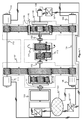
- Figure 1 illustrates the principle of a test rig according to an embodiment of the invention for testing a gearbox 118 and an electromechanical energy converter 119, e.g. a nacelle of a wind power station.
- the test rig comprises a gear system 101 and power transmission shafts 104 and 113.
- the gear system comprises first and second rotatable connection interfaces 102 and 103, e.g. flanges, suitable for being connected to input and output shafts of the gearbox 118 under test and a third rotatable connection interface 112 suitable for being connected to a shaft of the electromechanical energy converter 119 under test.
- the gear system 101 and the power transmission shafts 104 and 113 constitute together with the gearbox 118 under test two mechanical closed power loops as illustrated in figure 1 .
- the test rig comprises drive motors 108, 109, 110 and 111 for driving the mechanical closed power loops and/or the electromechanical energy converter 119 under test.
- the test rig comprises loading equipment for imposing test torque to the mechanically closed power loops so as to impose test torque to the gearbox 118 under test. Because the gearbox 118 under test is a part of the mechanically closed power loops, the sum of the power ratings of the drive motors 108-111 can be significantly lower than the maximum testing power of the gearbox under test.
- the gear system 101 is arranged to provide gear ratios so that the first rotatable connection interface 102 is arranged to rotate N 1 revolutions during a single revolution of the second rotatable connection interface 103 and N 2 revolutions during a single revolution of the third rotatable connection interface 112, where N 1 and N 2 are greater than unity.
- N 1 and N 2 can be, for example, at least 20 or at least 100.
- the first rotatable connection interface 102 of the test rig provides a higher speed-lower torque interface for the high speed side of the gearbox 118 under test
- the second rotatable connection interface 103 provides a lower speed-higher torque interface for the low speed side of a gearbox under test
- the third rotatable connection interface 112 provides a lower speed-higher torque interface for an electromechanical energy converter 119 under test.
- the maximum torque of the second rotatable connection interface 103 can be significantly higher than that of the third rotatable connection interface 112 because the second rotatable connection interface belongs to the mechanical closed power loops. Therefore, the above-described test rig is suitable for both testing the gearbox 118 as a component and also for testing the electromechanical energy converter 119, e.g. a nacelle of a wind power station, as a whole.
- each mechanical closed power loop there are two mechanical closed power loops in parallel.
- the power rating of the power transmission mechanism of each mechanical closed power loop can be significantly smaller than the maximum testing power of the gearbox 118 under test.
- it is easier, more room saving, and more cost effective to construct two smaller power transmission mechanisms instead of a single big power transmission mechanism.
- the number of the mechanical closed power loops could be also one or greater than two.
- the loading equipment for imposing the test torque to the gearbox 118 under test comprises a differential gear stage 105 having first and second rotatable elements 114 and 115 which form part of the mechanical closed power loops and whose mutual rotational speed difference depends on rotational speed of a third rotatable element 116 of the differential gear stage.
- the test rig is adapted to the gear ratio of the gearbox 118 under test by allowing the third rotatable element 116 of the differential gear stage to rotate at such a speed that the speed difference of the first and second rotatable elements 114 and 115 of the differential gear stage compensates the effect of the gear ratios of the other elements, including the gearbox under test, in the mechanical closed power loops.
- the differential gear stage is a planetary gear.
- the first and second rotatable elements 114 and 115 are the sun gear shaft of the planetary gear and the gear ring of the planetary gear, respectively.
- the gear ring has gear teeth also on its outer periphery.
- the third rotatable element 116 of the differential gear stage 105 is the planet-wheel carrier of the planetary gear.
- the differential gear stage could also be, for example, a spur-gear differential or a differential gear based on bevel gears.
- the loading equipment further comprises a controlling device connected to the third rotatable element 116 of the differential gear stage and arranged to control torque acting on the third rotatable element when the third rotatable element is rotating.
- the controlling device comprises an electrical machine 106 and an electrical converter device 107.
- the electrical converter is arranged to control the electrical machine 106 on the basis of a difference between the torque of the electrical machine and a reference torque.
- the electrical converter device 107 is arranged to change the reference torque in response to a situation in which the rotational speed of the electrical machine 106 meets an upper speed limit or a lower speed limit.
- the reference torque is changed in the direction that the rotational speed is returned to a speed window defined with the upper and lower speed limits.
- the electrical machine 106 can be an alternating current "AC" electrical machine and the electrical converter device 107 can be a frequency converter that is connected to a three-phase power supply network 120.
- An AC-electrical machine can be, for example, an induction machine or a permanent magnet synchronous machine.
- the frequency converter can be arranged use vector control that is based on controlling not only frequency and amplitudes of voltages and currents but also instantaneous phases of the voltages and currents. Especially, if a tachometer is used, very good control accuracy is achievable.
- the electrical machine could as well be a direct current "DC" electrical machine and the converter device could be an AC-to-DC converter, e.g. a thyristor converter.
- the controlling device connected to the third rotatable element 116 of the differential gear stage could be a simple brake but an inherent drawback of a brake is that it can produce only torque that is acting against a direction of rotation.
- An electrical machine can produce torque in both directions depending on whether the electrical machine operates as a motor or as a generator.
- the drive motors 108-111 that are arranged to drive the test rig are electrical motors that are supplied and controlled with an electrical converter device 117 arranged to control rotational speed of the electrical motors on the basis of a difference between the rotational speed of the electrical motors and a reference speed.
- the drive motors 108-111 are alternating current electrical motors and the electrical converter device 117 is a frequency converter.
- the converter device 117 can be arranged use the vector control. Especially, if a tachometer is used, it is possible to achieve very good speed control accuracy.
- the electrical motor is an AC-electrical motor that is directly connected to the power supply network 120.
- the rotational speeds of the drive motors 101-111 are determined by the frequency of the supply network but there can be significant fluctuations in the rotational speeds when there are dynamical changes in instantaneous loading conditions.
- the loading equipment comprises a hydraulically operated piston for pushing an obliquely toothed gearwheel in its axial direction with respect to its neighboring gearwheel that is also obliquely toothed.
- a hydraulically operated piston for pushing an obliquely toothed gearwheel in its axial direction with respect to its neighboring gearwheel that is also obliquely toothed.
- an axial movement of the gearwheel with respect to its neighboring gearwheel causes rotation and thus imposes torque to gearbox under test.
- It is also possible to generate the test torque by turning the whole gearbox under test as illustrated by the arrow 221 in figure 1 .
- the gearbox under test can be turned e.g. with the aid of a hydraulically operated piston. This method is, however, not suitable for a gearbox whose gear ratio is 1:1.
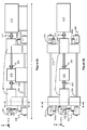
- Figure 2a shows a side view of a test rig according to an embodiment of the invention for testing a gearbox 218 and an electromechanical energy converter 219.
- Figure 2b shows the above-mentioned test rig seen above and figure 2c shows the section taken along the line A-A shown in figures 2a and 2b .
- the test rig comprises a gear system 201 and power transmission shafts 204 and 213.
- the gear system comprises first and second rotatable connection interfaces 202 and 203 suitable for being connected to input and output shafts of the gearbox 218 under test and a third rotatable connection interface 212 suitable for being connected to a shaft of the electromechanical energy converter 219 under test.
- the gear system 201 and the power transmission shafts 204 and 213 constitute together with the gearbox 218 under test two mechanical closed power loops as illustrated in figure 2b .
- the test rig comprises drive motors 208, 209, 210 and 211 for driving the mechanical closed power loops and/or the electromechanical energy converter 219 under test.
- the test rig comprises loading equipment for imposing test torque to the mechanically closed power loops so as to impose test torque to the gearbox 218 under test.
- the gear system 201 is arranged to provide gear ratios so that the first rotatable connection interface 202 is arranged to rotate N 1 revolutions during a single revolution of the second rotatable connection interface 203 and N 2 revolutions during a single revolution of the third rotatable connection interface 112, where N 1 and N 2 are greater than unity.
- the electromechanical energy converter 219 under test can be for example a nacelle of a wind power station and the gearbox 218 can be a gearbox similar to that of the nacelle.
- the ratings of the first rotatable connection interface 202 can be e.g. 24 MW, 1080 revolutions/min, and 212 kNm
- the ratings of the second rotatable connection interface 203 can be e.g.
- 24 MW, 9 revolutions/min, and 25500 kNm, and ratings of the third rotatable connection interface 212 can be e.g. 12 MW, 9 revolutions/min, and 12250 kNm.
- the total length L of the testing area can be about 60 m.
- the loading equipment comprises a differential gear stage 205 illustrated in the section A-A in figure 2c where gear teeth are depicted with dashed lines.
- the differential gear stage 205 can be similar to the differential gear stage 105 shown in figure 1 .
- the loading equipment further comprises electrical machines 206 and 206a that are connected to the planet-wheel carrier of the differential gear stage 205.
- the electrical machines 206 and 206a are supplied and controlled with an electrical converter device 207.
- the other end of the test rig may also comprise a differential gear stage which is used for generating the test torque and/or for adapting gear ratios and which is controlled with electrical machines 206b and 206c.
- Figure 3 shows a flow chart of a method according to an embodiment of the invention for testing a gearbox and an electromechanical energy converter with a same test rig.
- the method comprises:
- the actions 302, 303, and 305 take place simultaneously if the gearbox and the electromechanical energy converter are tested simultaneously.
- a method according to an embodiment of the invention further comprises adapting the gear ratio of the test rig to correspond to the gear ratio of the gearbox under test with the aid of a differential gear stage having first and second rotatable elements which form part of the mechanical closed power loop and whose mutual rotational speed difference depends on rotational speed of a third rotatable element of the differential gear stage.
- the test torque is imposed to the gearbox under test by controlling the torque acting on the third rotatable element when the third rotatable element is rotating.
- the torque acting on the third rotatable element is controlled with a system comprising:
- the differential gear stage can be, for example, a planetary gear so that the sun gear shaft and a gear ring of the planetary gear are the first and second rotatable elements, respectively, and a planet-wheel carrier of the planetary gear is the third rotatable element.
- the electrical machine can be an alternating current electrical machine and the electrical converter device can be a frequency converter.
- the reference torque is changed in response to a situation in which the rotational speed of the electrical machine meets an upper speed limit or a lower speed limit.
- the reference torque is changed in the direction that the rotational speed is returned to a speed window defined with the upper and lower speed limits.
- the test rig is driven with one or more electrical motors and rotational speed of the electrical motors is controlled on the basis of a difference between the rotational speed of the electrical motors and a reference speed.
- the electrical motors can be alternating current electrical motors that are supplied and controlled with a frequency converter.
Landscapes
- Physics & Mathematics (AREA)
- General Physics & Mathematics (AREA)
- Testing Of Devices, Machine Parts, Or Other Structures Thereof (AREA)
Claims (15)
- Banc d'essai pour tester une boîte de vitesses et un convertisseur d'énergie électromécanique, le banc d'essai comprenant :- un système d'engrenages (101, 201) comprenant des première et deuxième interfaces de liaison rotatives (102, 103, 202, 203) appropriées pour être reliées à des arbres d'entrée et de sortie de la boîte de vitesses qui est testée,un arbre de transmission de puissance (104, 204) constituant, avec le système d'engrenages et la boîte de vitesses qui est testée, une boucle d'entraînement fermée mécanique lorsque la boîte de vitesses qui est testée est reliée aux première et deuxième interfaces de liaison rotatives,- un équipement de charge (105 à 107, 205 à 207) pour appliquer un couple de test à la boîte de vitesses qui est testée, et- au moins un moteur d'entraînement (108 à 111, 208 à 211) pour entraîner le banc d'essai,caractérisé en ce que le système d'engrenages comprend de plus une troisième interface de liaison rotative (112, 212) appropriée pour être reliée à un arbre du convertisseur d'énergie électromécanique qui est testé, et en ce que le système d'engrenages est agencé de façon à produire des rapports de vitesse, de telle sorte que la première interface de liaison rotative soit agencée de façon à effectuer de nombreuses rotations durant une rotation unique de la deuxième interface de liaison rotative et durant une rotation unique de la troisième interface de liaison rotative.
- Banc d'essai selon la revendication 1, dans lequel la première interface de liaison rotative est agencée de façon à effectuer au moins 20 rotations durant une rotation unique de la deuxième interface de liaison rotative et durant une rotation unique de la troisième interface de liaison rotative.
- Banc d'essai selon la revendication 1, dans lequel la première interface de liaison rotative est agencée de façon à effectuer au moins 100 rotations durant une rotation unique de la deuxième interface de liaison rotative et durant une rotation unique de la troisième interface de liaison rotative.
- Banc d'essai selon l'une quelconque des revendications 1 à 3, dans lequel le banc d'essai comprend au moins un autre arbre de transmission de puissance (113, 213) constituant, avec le système d'engrenages et la boîte de vitesses qui est testée, au moins une autre boucle d'entraînement fermée mécanique.
- Banc d'essai selon l'une quelconque des revendications 1 à 4, dans lequel l'équipement de charge comprend :- un étage d'engrenages différentiels (105, 205) pour adapter le rapport de vitesse du banc d'essai de façon à correspondre au rapport de vitesse de la boîte de vitesses qui est testée, l'étage d'engrenages différentiels comprenant des premier et deuxième éléments rotatifs (114, 115) qui font partie de la boucle d'entraînement fermée mécanique, et dont la différence de vitesse de rotation mutuelle dépend de la vitesse de rotation d'un troisième élément rotatif (116) de l'étage d'engrenages différentiels, et- un dispositif de commande (106, 107, 206, 207) relié au troisième élément rotatif de l'étage d'engrenages différentiels, et agencé de façon à commander un couple agissant sur le troisième élément rotatif lorsque le troisième élément rotatif tourne, de façon à appliquer le couple de test à la boîte de vitesse qui est testée.
- Banc d'essai selon la revendication 5, dans lequel l'étage d'engrenages différentiels (105, 205) est un engrenage planétaire, un arbre de roue solaire et une couronne dentée de l'engrenage planétaire constituant les premier et deuxième éléments rotatifs, et un porte-satellites de l'engrenage planétaire constituant le troisième élément rotatif.
- Banc d'essai selon la revendication 5, dans lequel le dispositif de commande comprend une machine électrique (106, 206) et un dispositif de convertisseur électrique (107, 207) agencé de façon à commander la machine électrique en fonction d'une différence entre le couple de la machine électrique et un couple de référence.
- Banc d'essai selon la revendication 7, dans lequel le dispositif de convertisseur électrique est agencé de façon à changer le couple de référence en réponse à une situation dans laquelle la vitesse de rotation de la machine électrique satisfait à une limite de vitesse supérieure ou à une limite de vitesse inférieure, le couple de référence étant changé dans une direction telle que la vitesse de rotation soit rétablie dans une fenêtre de vitesse définie par les limites de vitesse supérieure et inférieure.
- Banc d'essai selon l'une quelconque des revendications 1 à 8, dans lequel le moteur d'entraînement (108 à 111) est un moteur électrique, et le banc d'essai comprend un autre dispositif de convertisseur électrique (117) agencé de façon à commander la vitesse de rotation du moteur électrique en fonction d'une différence entre la vitesse de rotation du moteur électrique et une vitesse de référence.
- Banc d'essai selon l'une quelconque des revendications 7 à 9, dans lequel la machine électrique est une machine électrique en courant alternatif et le dispositif de convertisseur électrique est un convertisseur de fréquence.
- Procédé pour tester une boîte de vitesses et un convertisseur d'énergie électromécanique avec un même banc d'essai, le procédé comprenant :- la liaison (301) d'arbres d'entrée et de sortie de la boîte de vitesses qui est testée à des première et deuxième interfaces de liaison rotatives du banc d'essai, le banc d'essai constituant avec la boîte de vitesses qui est testée au moins une boucle d'entraînement fermée mécanique,- l'entraînement (302) du banc d'essai de façon à délivrer des pertes de puissance mécanique à la boucle d'entraînement fermée mécanique, et- l'application (303) d'un couple de test à la boîte de vitesses qui est testée,caractérisé en ce que le procédé comprend de plus :- la liaison (304) d'un arbre du convertisseur d'énergie électromécanique qui est testé à une troisième interface de liaison rotative du banc d'essai, et- l'entraînement (305) du banc d'essai de façon à délivrer un entraînement de test mécanique au convertisseur d'énergie électromécanique qui est testé, dans lequel la première interface de liaison rotative effectue de nombreuses rotations durant une rotation unique de la deuxième interface de liaison rotative et durant une rotation unique de la troisième interface de liaison rotative.
- Procédé selon la revendication 11, dans lequel le procédé comprend de plus l'adaptation du rapport de vitesse du banc d'essai de façon à correspondre au rapport de vitesse de la boîte de vitesses qui est testée à l'aide d'un étage d'engrenages différentiels comportant des premier et deuxième éléments rotatifs qui font partie de la boucle d'entraînement fermée mécanique, et dont la différence de vitesse de rotation mutuelle dépend de la vitesse de rotation d'un troisième élément rotatif de l'étage d'engrenages différentiels, et dans lequel le couple de test est appliqué à la boîte de vitesses qui est testée par la commande d'un couple agissant sur le troisième élément rotatif lorsque le troisième élément rotatif tourne.
- Procédé selon la revendication 12, dans lequel l'étage d'engrenages différentiels est un engrenage planétaire, un arbre de roue solaire et une couronne dentée de l'engrenage planétaire constituant les premier et deuxième éléments rotatifs, et un porte-satellites de l'engrenage planétaire constituant le troisième élément rotatif.
- Procédé selon la revendication 12, dans lequel le couple agissant sur le troisième élément rotatif est commandé par un système comprenant une machine électrique et un dispositif de convertisseur électrique qui commande la machine électrique en fonction d'une différence entre le couple de la machine électrique et un couple de référence.
- Procédé selon la revendication 14, dans lequel le couple de référence est changé en réponse à une situation dans laquelle la vitesse de rotation de la machine électrique satisfait à une limite de vitesse supérieure ou à une limite de vitesse inférieure, le couple de référence étant changé dans une direction dans laquelle la vitesse de rotation est rétablie dans une fenêtre de vitesse définie par les limites de vitesse supérieure et inférieure.
Priority Applications (3)
| Application Number | Priority Date | Filing Date | Title |
|---|---|---|---|
| DK11183289.5T DK2574778T3 (en) | 2011-09-29 | 2011-09-29 | Experimental setup and method for testing of gearboxes and electromechanical energy converters |
| ES11183289.5T ES2555067T3 (es) | 2011-09-29 | 2011-09-29 | Instalación de ensayo y método para ensayar cajas de engranajes y convertidores de energía electromecánicos |
| EP11183289.5A EP2574778B1 (fr) | 2011-09-29 | 2011-09-29 | Banc d'essai et procédé de test de boîtes de vitesses et convertisseurs d'énergie électro-mécaniques |
Applications Claiming Priority (1)
| Application Number | Priority Date | Filing Date | Title |
|---|---|---|---|
| EP11183289.5A EP2574778B1 (fr) | 2011-09-29 | 2011-09-29 | Banc d'essai et procédé de test de boîtes de vitesses et convertisseurs d'énergie électro-mécaniques |
Publications (2)
| Publication Number | Publication Date |
|---|---|
| EP2574778A1 EP2574778A1 (fr) | 2013-04-03 |
| EP2574778B1 true EP2574778B1 (fr) | 2015-09-09 |
Family
ID=44719562
Family Applications (1)
| Application Number | Title | Priority Date | Filing Date |
|---|---|---|---|
| EP11183289.5A Active EP2574778B1 (fr) | 2011-09-29 | 2011-09-29 | Banc d'essai et procédé de test de boîtes de vitesses et convertisseurs d'énergie électro-mécaniques |
Country Status (3)
| Country | Link |
|---|---|
| EP (1) | EP2574778B1 (fr) |
| DK (1) | DK2574778T3 (fr) |
| ES (1) | ES2555067T3 (fr) |
Cited By (1)
| Publication number | Priority date | Publication date | Assignee | Title |
|---|---|---|---|---|
| EP3859297A1 (fr) | 2020-01-31 | 2021-08-04 | Flender GmbH | Dispositif d'essai pour transmissions, procédure d'essai, unité de commande et produit programme informatique |
Families Citing this family (8)
| Publication number | Priority date | Publication date | Assignee | Title |
|---|---|---|---|---|
| CN104634564A (zh) * | 2013-11-12 | 2015-05-20 | 陕西国力信息技术有限公司 | 一种amt系统低温工作试验方法 |
| CN105716856A (zh) * | 2014-12-01 | 2016-06-29 | 株洲高精齿轮有限公司 | 一种齿轮跑合装置 |
| CN104634568B (zh) * | 2015-02-02 | 2017-08-15 | 长安大学 | 一种利用液力偶合器加载的闭式驱动桥测试装置 |
| CN104614181B (zh) * | 2015-02-02 | 2017-10-10 | 长安大学 | 闭式功率传递的液力机械传动试验台 |
| CN104819844B (zh) * | 2015-05-22 | 2017-06-16 | 无锡城市职业技术学院 | 手动变速器寿命试验装置 |
| CN107515116A (zh) * | 2017-09-23 | 2017-12-26 | 吉林大学 | 可倾斜单齿轮箱电功率闭环加载试验系统 |
| CN108225765A (zh) * | 2018-01-31 | 2018-06-29 | 宁夏天地奔牛实业集团有限公司 | 掘锚机截割齿轮箱效率检验系统及效率检验方法 |
| WO2019219160A1 (fr) * | 2018-05-14 | 2019-11-21 | R&D A/S | Système d'entraînement modulaire, unité de charge et banc d'essai comprenant ledit système d'entraînement modulaire |
Family Cites Families (4)
| Publication number | Priority date | Publication date | Assignee | Title |
|---|---|---|---|---|
| US3112643A (en) | 1960-05-02 | 1963-12-03 | Bendix Corp | Test apparatus having a regenerative system for loading rotating devices |
| WO2007144003A2 (fr) * | 2006-07-03 | 2007-12-21 | Vestas Wind Systems A/S | Banc d'essai et procédé d'essai d'un équipement de turbine éolienne |
| ES2377841T3 (es) * | 2006-07-03 | 2012-04-02 | Vestas Wind Systems A/S | Banco de pruebas que comprende un medio de ajuste de ángulo y procedimientos para someter a prueba un equipo de turbina eólica |
| US8584530B2 (en) * | 2009-08-19 | 2013-11-19 | Avl Test Systems, Inc. | Wind turbine gearbox testing system |
-
2011
- 2011-09-29 ES ES11183289.5T patent/ES2555067T3/es active Active
- 2011-09-29 EP EP11183289.5A patent/EP2574778B1/fr active Active
- 2011-09-29 DK DK11183289.5T patent/DK2574778T3/en active
Cited By (2)
| Publication number | Priority date | Publication date | Assignee | Title |
|---|---|---|---|---|
| EP3859297A1 (fr) | 2020-01-31 | 2021-08-04 | Flender GmbH | Dispositif d'essai pour transmissions, procédure d'essai, unité de commande et produit programme informatique |
| WO2021151635A1 (fr) | 2020-01-31 | 2021-08-05 | Flender Gmbh | Dispositif de test pour mécanismes d'engrenage, procédé de test, unité de commande et produit programme d'ordinateur |
Also Published As
| Publication number | Publication date |
|---|---|
| EP2574778A1 (fr) | 2013-04-03 |
| DK2574778T3 (en) | 2015-12-21 |
| ES2555067T3 (es) | 2015-12-28 |
Similar Documents
| Publication | Publication Date | Title |
|---|---|---|
| EP2574778B1 (fr) | Banc d'essai et procédé de test de boîtes de vitesses et convertisseurs d'énergie électro-mécaniques | |
| EP2574898B1 (fr) | Banc d'essai et procédé de test de boîtes de vitesses | |
| Frank et al. | Gearing ratios of a magnetic gear for wind turbines | |
| Ragheb et al. | Wind turbine gearbox technologies | |
| US10180178B2 (en) | Gearbox and drive arrangement with a gearbox | |
| Yin et al. | Current status and future prospects of continuously variable speed wind turbines: A systematic review | |
| EP2574777B1 (fr) | Banc d'essai et procédé de test de boîtes de vitesses dotées de différents rapports de transmission | |
| US8698341B2 (en) | Wind turbine with discretely variable diameter gear box | |
| AT511720B1 (de) | Energiegewinnungsanlage | |
| US8282351B2 (en) | Split load path gearbox | |
| KR0163825B1 (ko) | 변속입력 정속출력 기어장치 | |
| DK201070321A (en) | A wind turbine comprising a detuner | |
| CN103986278A (zh) | 异联电机 | |
| KR101028960B1 (ko) | 풍력터빈설비 | |
| GB2483866A (en) | Electric generator apparatus for a fluid turbine arrangement | |
| CN108591400B (zh) | 动力传输装置及包括这种动力传输装置的风力机 | |
| Goudarzi et al. | Offshore and onshore wind energy conversion: the potential of a novel multiple-generator drivetrain | |
| Chen | Wind turbine drive train systems | |
| JP5752365B2 (ja) | 発電システム | |
| Taherian-Fard et al. | Wind turbine drivetrains: A glimpse of existing technologies | |
| WO2012093492A1 (fr) | Équipement de test pour machine rotative | |
| Hwang et al. | An innovative transmission mechanism applicable to variable speed wind turbines | |
| RU2359900C2 (ru) | Привод лифта | |
| Goudarzi et al. | Studying the Potential of a Novel Multiple-Generator Drivetrain in Wind Energy Conversion Systems | |
| DOE | Advanced Wind Turbine Drivetrain Concepts: Workshop Report, June 29-30, 2010 |
Legal Events
| Date | Code | Title | Description |
|---|---|---|---|
| PUAI | Public reference made under article 153(3) epc to a published international application that has entered the european phase |
Free format text: ORIGINAL CODE: 0009012 |
|
| AK | Designated contracting states |
Kind code of ref document: A1 Designated state(s): AL AT BE BG CH CY CZ DE DK EE ES FI FR GB GR HR HU IE IS IT LI LT LU LV MC MK MT NL NO PL PT RO RS SE SI SK SM TR |
|
| AX | Request for extension of the european patent |
Extension state: BA ME |
|
| 17P | Request for examination filed |
Effective date: 20130923 |
|
| RBV | Designated contracting states (corrected) |
Designated state(s): AL AT BE BG CH CY CZ DE DK EE ES FI FR GB GR HR HU IE IS IT LI LT LU LV MC MK MT NL NO PL PT RO RS SE SI SK SM TR |
|
| GRAP | Despatch of communication of intention to grant a patent |
Free format text: ORIGINAL CODE: EPIDOSNIGR1 |
|
| INTG | Intention to grant announced |
Effective date: 20150415 |
|
| GRAS | Grant fee paid |
Free format text: ORIGINAL CODE: EPIDOSNIGR3 |
|
| GRAA | (expected) grant |
Free format text: ORIGINAL CODE: 0009210 |
|
| AK | Designated contracting states |
Kind code of ref document: B1 Designated state(s): AL AT BE BG CH CY CZ DE DK EE ES FI FR GB GR HR HU IE IS IT LI LT LU LV MC MK MT NL NO PL PT RO RS SE SI SK SM TR |
|
| REG | Reference to a national code |
Ref country code: GB Ref legal event code: FG4D |
|
| REG | Reference to a national code |
Ref country code: AT Ref legal event code: REF Ref document number: 748353 Country of ref document: AT Kind code of ref document: T Effective date: 20150915 Ref country code: CH Ref legal event code: EP |
|
| REG | Reference to a national code |
Ref country code: IE Ref legal event code: FG4D |
|
| REG | Reference to a national code |
Ref country code: DE Ref legal event code: R096 Ref document number: 602011019541 Country of ref document: DE |
|
| REG | Reference to a national code |
Ref country code: FR Ref legal event code: PLFP Year of fee payment: 5 |
|
| REG | Reference to a national code |
Ref country code: DK Ref legal event code: T3 Effective date: 20151217 |
|
| REG | Reference to a national code |
Ref country code: ES Ref legal event code: FG2A Ref document number: 2555067 Country of ref document: ES Kind code of ref document: T3 Effective date: 20151228 |
|
| REG | Reference to a national code |
Ref country code: NL Ref legal event code: MP Effective date: 20150909 |
|
| PG25 | Lapsed in a contracting state [announced via postgrant information from national office to epo] |
Ref country code: LV Free format text: LAPSE BECAUSE OF FAILURE TO SUBMIT A TRANSLATION OF THE DESCRIPTION OR TO PAY THE FEE WITHIN THE PRESCRIBED TIME-LIMIT Effective date: 20150909 Ref country code: NO Free format text: LAPSE BECAUSE OF FAILURE TO SUBMIT A TRANSLATION OF THE DESCRIPTION OR TO PAY THE FEE WITHIN THE PRESCRIBED TIME-LIMIT Effective date: 20151209 Ref country code: GR Free format text: LAPSE BECAUSE OF FAILURE TO SUBMIT A TRANSLATION OF THE DESCRIPTION OR TO PAY THE FEE WITHIN THE PRESCRIBED TIME-LIMIT Effective date: 20151210 Ref country code: LT Free format text: LAPSE BECAUSE OF FAILURE TO SUBMIT A TRANSLATION OF THE DESCRIPTION OR TO PAY THE FEE WITHIN THE PRESCRIBED TIME-LIMIT Effective date: 20150909 |
|
| REG | Reference to a national code |
Ref country code: LT Ref legal event code: MG4D |
|
| REG | Reference to a national code |
Ref country code: AT Ref legal event code: MK05 Ref document number: 748353 Country of ref document: AT Kind code of ref document: T Effective date: 20150909 |
|
| PG25 | Lapsed in a contracting state [announced via postgrant information from national office to epo] |
Ref country code: RS Free format text: LAPSE BECAUSE OF FAILURE TO SUBMIT A TRANSLATION OF THE DESCRIPTION OR TO PAY THE FEE WITHIN THE PRESCRIBED TIME-LIMIT Effective date: 20150909 Ref country code: SE Free format text: LAPSE BECAUSE OF FAILURE TO SUBMIT A TRANSLATION OF THE DESCRIPTION OR TO PAY THE FEE WITHIN THE PRESCRIBED TIME-LIMIT Effective date: 20150909 Ref country code: HR Free format text: LAPSE BECAUSE OF FAILURE TO SUBMIT A TRANSLATION OF THE DESCRIPTION OR TO PAY THE FEE WITHIN THE PRESCRIBED TIME-LIMIT Effective date: 20150909 |
|
| PG25 | Lapsed in a contracting state [announced via postgrant information from national office to epo] |
Ref country code: NL Free format text: LAPSE BECAUSE OF FAILURE TO SUBMIT A TRANSLATION OF THE DESCRIPTION OR TO PAY THE FEE WITHIN THE PRESCRIBED TIME-LIMIT Effective date: 20150909 |
|
| PG25 | Lapsed in a contracting state [announced via postgrant information from national office to epo] |
Ref country code: IS Free format text: LAPSE BECAUSE OF FAILURE TO SUBMIT A TRANSLATION OF THE DESCRIPTION OR TO PAY THE FEE WITHIN THE PRESCRIBED TIME-LIMIT Effective date: 20160109 Ref country code: SK Free format text: LAPSE BECAUSE OF FAILURE TO SUBMIT A TRANSLATION OF THE DESCRIPTION OR TO PAY THE FEE WITHIN THE PRESCRIBED TIME-LIMIT Effective date: 20150909 Ref country code: EE Free format text: LAPSE BECAUSE OF FAILURE TO SUBMIT A TRANSLATION OF THE DESCRIPTION OR TO PAY THE FEE WITHIN THE PRESCRIBED TIME-LIMIT Effective date: 20150909 |
|
| REG | Reference to a national code |
Ref country code: CH Ref legal event code: PL |
|
| PG25 | Lapsed in a contracting state [announced via postgrant information from national office to epo] |
Ref country code: RO Free format text: LAPSE BECAUSE OF FAILURE TO SUBMIT A TRANSLATION OF THE DESCRIPTION OR TO PAY THE FEE WITHIN THE PRESCRIBED TIME-LIMIT Effective date: 20150909 Ref country code: AT Free format text: LAPSE BECAUSE OF FAILURE TO SUBMIT A TRANSLATION OF THE DESCRIPTION OR TO PAY THE FEE WITHIN THE PRESCRIBED TIME-LIMIT Effective date: 20150909 Ref country code: PT Free format text: LAPSE BECAUSE OF FAILURE TO SUBMIT A TRANSLATION OF THE DESCRIPTION OR TO PAY THE FEE WITHIN THE PRESCRIBED TIME-LIMIT Effective date: 20160111 Ref country code: PL Free format text: LAPSE BECAUSE OF FAILURE TO SUBMIT A TRANSLATION OF THE DESCRIPTION OR TO PAY THE FEE WITHIN THE PRESCRIBED TIME-LIMIT Effective date: 20150909 |
|
| REG | Reference to a national code |
Ref country code: DE Ref legal event code: R097 Ref document number: 602011019541 Country of ref document: DE |
|
| REG | Reference to a national code |
Ref country code: IE Ref legal event code: MM4A |
|
| PG25 | Lapsed in a contracting state [announced via postgrant information from national office to epo] |
Ref country code: MC Free format text: LAPSE BECAUSE OF FAILURE TO SUBMIT A TRANSLATION OF THE DESCRIPTION OR TO PAY THE FEE WITHIN THE PRESCRIBED TIME-LIMIT Effective date: 20150909 |
|
| PLBE | No opposition filed within time limit |
Free format text: ORIGINAL CODE: 0009261 |
|
| STAA | Information on the status of an ep patent application or granted ep patent |
Free format text: STATUS: NO OPPOSITION FILED WITHIN TIME LIMIT |
|
| PG25 | Lapsed in a contracting state [announced via postgrant information from national office to epo] |
Ref country code: CH Free format text: LAPSE BECAUSE OF NON-PAYMENT OF DUE FEES Effective date: 20150930 Ref country code: IE Free format text: LAPSE BECAUSE OF NON-PAYMENT OF DUE FEES Effective date: 20150929 Ref country code: LI Free format text: LAPSE BECAUSE OF NON-PAYMENT OF DUE FEES Effective date: 20150930 |
|
| 26N | No opposition filed |
Effective date: 20160610 |
|
| PG25 | Lapsed in a contracting state [announced via postgrant information from national office to epo] |
Ref country code: SI Free format text: LAPSE BECAUSE OF FAILURE TO SUBMIT A TRANSLATION OF THE DESCRIPTION OR TO PAY THE FEE WITHIN THE PRESCRIBED TIME-LIMIT Effective date: 20150909 |
|
| REG | Reference to a national code |
Ref country code: FR Ref legal event code: PLFP Year of fee payment: 6 |
|
| PG25 | Lapsed in a contracting state [announced via postgrant information from national office to epo] |
Ref country code: BE Free format text: LAPSE BECAUSE OF FAILURE TO SUBMIT A TRANSLATION OF THE DESCRIPTION OR TO PAY THE FEE WITHIN THE PRESCRIBED TIME-LIMIT Effective date: 20150909 |
|
| PG25 | Lapsed in a contracting state [announced via postgrant information from national office to epo] |
Ref country code: MT Free format text: LAPSE BECAUSE OF FAILURE TO SUBMIT A TRANSLATION OF THE DESCRIPTION OR TO PAY THE FEE WITHIN THE PRESCRIBED TIME-LIMIT Effective date: 20150909 |
|
| PG25 | Lapsed in a contracting state [announced via postgrant information from national office to epo] |
Ref country code: BG Free format text: LAPSE BECAUSE OF FAILURE TO SUBMIT A TRANSLATION OF THE DESCRIPTION OR TO PAY THE FEE WITHIN THE PRESCRIBED TIME-LIMIT Effective date: 20150909 Ref country code: SM Free format text: LAPSE BECAUSE OF FAILURE TO SUBMIT A TRANSLATION OF THE DESCRIPTION OR TO PAY THE FEE WITHIN THE PRESCRIBED TIME-LIMIT Effective date: 20150909 Ref country code: HU Free format text: LAPSE BECAUSE OF FAILURE TO SUBMIT A TRANSLATION OF THE DESCRIPTION OR TO PAY THE FEE WITHIN THE PRESCRIBED TIME-LIMIT; INVALID AB INITIO Effective date: 20110929 |
|
| PG25 | Lapsed in a contracting state [announced via postgrant information from national office to epo] |
Ref country code: CY Free format text: LAPSE BECAUSE OF FAILURE TO SUBMIT A TRANSLATION OF THE DESCRIPTION OR TO PAY THE FEE WITHIN THE PRESCRIBED TIME-LIMIT Effective date: 20150909 |
|
| PG25 | Lapsed in a contracting state [announced via postgrant information from national office to epo] |
Ref country code: TR Free format text: LAPSE BECAUSE OF FAILURE TO SUBMIT A TRANSLATION OF THE DESCRIPTION OR TO PAY THE FEE WITHIN THE PRESCRIBED TIME-LIMIT Effective date: 20150909 |
|
| REG | Reference to a national code |
Ref country code: FR Ref legal event code: PLFP Year of fee payment: 7 |
|
| PG25 | Lapsed in a contracting state [announced via postgrant information from national office to epo] |
Ref country code: LU Free format text: LAPSE BECAUSE OF NON-PAYMENT OF DUE FEES Effective date: 20150929 |
|
| PG25 | Lapsed in a contracting state [announced via postgrant information from national office to epo] |
Ref country code: MK Free format text: LAPSE BECAUSE OF FAILURE TO SUBMIT A TRANSLATION OF THE DESCRIPTION OR TO PAY THE FEE WITHIN THE PRESCRIBED TIME-LIMIT Effective date: 20150909 |
|
| REG | Reference to a national code |
Ref country code: FR Ref legal event code: PLFP Year of fee payment: 8 |
|
| PG25 | Lapsed in a contracting state [announced via postgrant information from national office to epo] |
Ref country code: AL Free format text: LAPSE BECAUSE OF FAILURE TO SUBMIT A TRANSLATION OF THE DESCRIPTION OR TO PAY THE FEE WITHIN THE PRESCRIBED TIME-LIMIT Effective date: 20150909 |
|
| PGFP | Annual fee paid to national office [announced via postgrant information from national office to epo] |
Ref country code: GB Payment date: 20220920 Year of fee payment: 12 Ref country code: FI Payment date: 20220921 Year of fee payment: 12 Ref country code: DK Payment date: 20220922 Year of fee payment: 12 Ref country code: DE Payment date: 20220920 Year of fee payment: 12 Ref country code: CZ Payment date: 20220919 Year of fee payment: 12 |
|
| PGFP | Annual fee paid to national office [announced via postgrant information from national office to epo] |
Ref country code: FR Payment date: 20220922 Year of fee payment: 12 |
|
| PGFP | Annual fee paid to national office [announced via postgrant information from national office to epo] |
Ref country code: IT Payment date: 20220926 Year of fee payment: 12 Ref country code: ES Payment date: 20221122 Year of fee payment: 12 |
|
| REG | Reference to a national code |
Ref country code: DE Ref legal event code: R119 Ref document number: 602011019541 Country of ref document: DE |
|
| REG | Reference to a national code |
Ref country code: DK Ref legal event code: EBP Effective date: 20230930 |
|
| PG25 | Lapsed in a contracting state [announced via postgrant information from national office to epo] |
Ref country code: FI Free format text: LAPSE BECAUSE OF NON-PAYMENT OF DUE FEES Effective date: 20230929 Ref country code: CZ Free format text: LAPSE BECAUSE OF NON-PAYMENT OF DUE FEES Effective date: 20230929 |
|
| GBPC | Gb: european patent ceased through non-payment of renewal fee |
Effective date: 20230929 |