EP4097441B1 - Dispositif d'essai pour transmissions, procédure d'essai, unité de commande et produit programme informatique - Google Patents
Dispositif d'essai pour transmissions, procédure d'essai, unité de commande et produit programme informatique Download PDFInfo
- Publication number
- EP4097441B1 EP4097441B1 EP21701892.8A EP21701892A EP4097441B1 EP 4097441 B1 EP4097441 B1 EP 4097441B1 EP 21701892 A EP21701892 A EP 21701892A EP 4097441 B1 EP4097441 B1 EP 4097441B1
- Authority
- EP
- European Patent Office
- Prior art keywords
- testing device
- gearbox
- test
- gearboxes
- control unit
- Prior art date
- Legal status (The legal status is an assumption and is not a legal conclusion. Google has not performed a legal analysis and makes no representation as to the accuracy of the status listed.)
- Active
Links
- 238000012360 testing method Methods 0.000 title claims description 191
- 230000005540 biological transmission Effects 0.000 title claims description 79
- 238000004590 computer program Methods 0.000 title claims description 27
- 238000006243 chemical reaction Methods 0.000 claims description 75
- 238000000034 method Methods 0.000 claims description 18
- 238000006073 displacement reaction Methods 0.000 claims description 11
- 230000003213 activating effect Effects 0.000 claims 1
- 238000005259 measurement Methods 0.000 description 18
- 238000010586 diagram Methods 0.000 description 5
- 230000008859 change Effects 0.000 description 4
- 238000012423 maintenance Methods 0.000 description 4
- 238000010276 construction Methods 0.000 description 3
- 230000008569 process Effects 0.000 description 3
- 238000004088 simulation Methods 0.000 description 3
- 238000013519 translation Methods 0.000 description 3
- 230000009467 reduction Effects 0.000 description 2
- 238000012935 Averaging Methods 0.000 description 1
- 210000004534 cecum Anatomy 0.000 description 1
- 238000013461 design Methods 0.000 description 1
- 238000011161 development Methods 0.000 description 1
- 230000005611 electricity Effects 0.000 description 1
- 230000007613 environmental effect Effects 0.000 description 1
- 239000012530 fluid Substances 0.000 description 1
- 230000006872 improvement Effects 0.000 description 1
- 230000007774 longterm Effects 0.000 description 1
- 238000004519 manufacturing process Methods 0.000 description 1
- 230000000149 penetrating effect Effects 0.000 description 1
- 230000001105 regulatory effect Effects 0.000 description 1
- 238000010972 statistical evaluation Methods 0.000 description 1
- 238000012546 transfer Methods 0.000 description 1
- 230000007704 transition Effects 0.000 description 1
Images
Classifications
-
- G—PHYSICS
- G01—MEASURING; TESTING
- G01M—TESTING STATIC OR DYNAMIC BALANCE OF MACHINES OR STRUCTURES; TESTING OF STRUCTURES OR APPARATUS, NOT OTHERWISE PROVIDED FOR
- G01M13/00—Testing of machine parts
- G01M13/02—Gearings; Transmission mechanisms
- G01M13/025—Test-benches with rotational drive means and loading means; Load or drive simulation
-
- G—PHYSICS
- G01—MEASURING; TESTING
- G01M—TESTING STATIC OR DYNAMIC BALANCE OF MACHINES OR STRUCTURES; TESTING OF STRUCTURES OR APPARATUS, NOT OTHERWISE PROVIDED FOR
- G01M13/00—Testing of machine parts
- G01M13/02—Gearings; Transmission mechanisms
- G01M13/021—Gearings
-
- G—PHYSICS
- G01—MEASURING; TESTING
- G01M—TESTING STATIC OR DYNAMIC BALANCE OF MACHINES OR STRUCTURES; TESTING OF STRUCTURES OR APPARATUS, NOT OTHERWISE PROVIDED FOR
- G01M13/00—Testing of machine parts
- G01M13/02—Gearings; Transmission mechanisms
- G01M13/022—Power-transmitting couplings or clutches
-
- Y—GENERAL TAGGING OF NEW TECHNOLOGICAL DEVELOPMENTS; GENERAL TAGGING OF CROSS-SECTIONAL TECHNOLOGIES SPANNING OVER SEVERAL SECTIONS OF THE IPC; TECHNICAL SUBJECTS COVERED BY FORMER USPC CROSS-REFERENCE ART COLLECTIONS [XRACs] AND DIGESTS
- Y02—TECHNOLOGIES OR APPLICATIONS FOR MITIGATION OR ADAPTATION AGAINST CLIMATE CHANGE
- Y02E—REDUCTION OF GREENHOUSE GAS [GHG] EMISSIONS, RELATED TO ENERGY GENERATION, TRANSMISSION OR DISTRIBUTION
- Y02E10/00—Energy generation through renewable energy sources
- Y02E10/70—Wind energy
- Y02E10/72—Wind turbines with rotation axis in wind direction
Definitions
- the invention relates to a testing device for transmissions and a corresponding testing method.
- the invention also relates to a control unit which is designed to carry out the testing method according to the invention on such a testing device.
- the invention further relates to a computer program product that can be stored and executed on the control unit in order to carry out the testing method.
- test benches used there for nacelles of wind turbines and their drive trains.
- the test benches are designed for maximum drive powers of 7.5 MW and 15 MW.
- At least one drive motor is arranged on each test bench, which is connected to a countershaft gear via a high-speed shaft.
- a low-speed shaft emerges from the countershaft gear and is used to drive a rotor of a wind turbine nacelle to be tested.
- the rotor of the wind turbine nacelle is connected by means of a substantially toroidal load introduction unit, which is suitable for simulating operating states of the wind turbine.
- a wind turbine gearbox test stand is known on which two gearboxes can be mounted.
- the gearboxes are driven by a drive unit that is connected to a load unit by means of a torsion bar.
- the loading unit is connected to two torsion bars that can be braced against each other.
- the document EP 2 574 778 B1 shows a testing device for a transmission and an electromechanical energy converter, in which the transmission to be tested is mounted in a transmission system.
- the transmission to be tested is supplied with drive power via several motors, which is also fed into the electromechanical energy converter.
- the DE 10 2012 021 007 A1 discloses a test device for wind turbine transmissions. Two gearboxes are connected to each other via an actively rotatable center shaft.
- the gearboxes are each attached to a gearbox holder that is rigidly connected to the ground.
- the two gears can undergo a rotational change in position relative to one another. This aims to change the relative position of the two transmission shafts to each other to avoid interference, vibration and noise.
- High-performance gearboxes are used in various areas of application, the development process or approval process of which requires testing of the corresponding gearboxes. There is therefore a need for a testing device for transmissions that allows test runs to be carried out quickly, offers a high degree of flexibility and can be manufactured in a simple manner.
- the invention is based on the task of providing a possibility for testing transmissions that offers an improvement in at least one of the aspects outlined.
- the testing device for transmissions which comprises a drive unit and an output unit.
- the drive unit provides mechanical drive power with which the transmissions to be tested can be driven.
- the drive unit can be designed, for example, as an electric motor.
- the output unit is designed to absorb the mechanical drive power passed through the gearbox.
- the output unit can be designed, for example, as a generator or as a brake.
- the drive unit and the output unit are connected to one another via a first and a second gear, which are to be tested with the testing device. The connection via the first and second gears directs the mechanical drive power from the drive unit to the output unit. By adjusting the mechanical drive power, the speeds present in the first and second transmissions can be specified as part of a test run.
- the first gear is designed to be tiltable and/or displaceable in an adjustable manner.
- the testing device is accordingly designed to tilt and/or shift at least the first gear in an adjustable manner when the first gear is connected to the testing device as intended.
- the tilting takes place about at least one spatial axis, which can be aligned perpendicular to a main axis of rotation of the first gear, or coincides with the main axis of rotation of the first gear.
- the shifting takes place translationally along at least one of the spatial axes. Tilting and/or shifting also causes a mechanical reaction on the second gear.
- the first gear and the second gear can therefore be tested at least partially at the same time.
- the first and second transmissions can be of different types, i.e. not identical in construction or mutually interchangeable.
- the difference in types also includes the case of a first and second gearbox, which have different components in certain areas. These can be, for example, gearboxes with different bearings but otherwise the same structure.
- gearboxes in which components are manufactured using different manufacturing processes but otherwise have the same structure can also be tested at least partially at the same time. This makes it possible to test different types, models or variants of transmissions in a joint test run, which reduces the number of test runs required, for example for a test program. The number of test runs required can therefore essentially be halved, which allows for economical test operations overall.
- the claimed testing device can generate a mechanical reaction by tilting and/or moving the first gear between the first and second gears.
- the mechanical reaction includes a reaction force and/or a reaction torque. This makes it possible to simulate real operation of the transmission, in which the mechanical drive power is introduced with a deviation from an idealized main axis of rotation. This makes it possible to simulate a real operating state with changing wind conditions, particularly for gearboxes that are to be used in wind turbines.
- the mechanical reaction which includes the reaction force and/or the reaction torque, can therefore be specified in a targeted manner and is suitable for being part of a test run as an operating condition specification that is to be carried out with the test device.
- this allows a user, an algorithm or a table, for example, to specify a wide range of programs for testing the transmissions.
- Such a link is guaranteed in a simple way to compare the two transmissions under corresponding operating conditions. This can also shorten the overall duration required for a testing program.
- the second gear is also designed to be tiltable and/or displaceable.
- the tiltability or displaceability of the second gear can correspond to the tiltability of the first gear.
- the testing device analogous to the tiltability and/or displaceability of the first gear, is also designed to tilt and/or shift the second gear in an adjustable manner.
- the tiltability and/or displaceability of the second gear makes it possible to produce a wider range of stresses and thus reaction forces and/or reaction torques during a test run.
- the first and second gears can be tilted and/or displaced at the same time and thereby a deflection to be set can be divided into several tilting and/or displacement movements. This further increases the flexibility of the claimed testing device.
- the claimed testing device has actuators which are designed to tilt and/or move at least the first gear.
- the actuators are firmly connected to the environment.
- the actuators can also be arranged between the first and second gears and/or can be designed as rotating actuators.
- the actuators can be designed as hydraulic cylinders, servo motors and/or spindle drives. Actuators, especially hydraulic cylinders, are available in different designs that provide high actuation force at the same time offer high actuation precision. Likewise, reached actuation positions of the actuators can be maintained precisely.
- the first gear can be tilted and/or displaced via several actuators, whereby the advantages outlined are achieved to an increased extent.
- the second gear is designed to be tiltable and/or displaceable via several actuators. This also means that the described advantages of a precise test run are achieved to an increased extent.
- Actuators such as hydraulic cylinders are also available in a variety of sizes. A technically complex toroidal or crown-shaped load introduction unit is not necessary in the claimed test unit. Such actuators can also be repaired in a simple manner, which allows for particularly cost-effective maintenance. As a result, the claimed solution offers a particularly high level of economic efficiency overall.
- the first transmission in the claimed testing device is arranged on a tiltable support frame.
- a support frame can be arranged, for example, on joint supports and/or at least one actuator. The spatial position of the support frame can be changed by actuating the at least one actuator.
- the first gearbox is mounted on a test mount on the support frame.
- the second gear is also arranged on such a support frame.
- the use of support frames offers an overall uniform test setup on the claimed testing device, which is suitable for a variety of different types of transmissions and allows a simplified test run.
- the first and second gears are connected to one another in opposite translation directions.
- Such an arrangement is also called a back-to-back arrangement.
- the output unit is thereby supplied with the mechanical drive power at a speed that is similar or identical or different to that when it exits the drive unit, taking mechanical losses into account.
- the drive unit and the output unit for example an electric motor and a generator, can therefore be designed, for example, as identical electromechanical machines operating in opposite directions.
- the actuators can be attached to the surface. This ensures a stable connection with the environment, which in turn allows test runs to be carried out precisely over the long term.
- the actuators can be arranged below the at least first transmission.
- a plurality be arranged on actuators on a foundation that is accommodated below a floor level.
- the floor level here is to be understood as meaning a floor level in the surrounding area, for example a hall floor.
- the foundation can therefore essentially be located in a basement-like depression.
- the actuators are at least partially arranged below the floor level.
- the actuators can therefore be positioned on a reduced foundation area, which in turn requires reduced construction effort.
- the testing device has a reduced vertical dimension.
- the claimed testing device allows the testing device to be set up in a low hall, which also allows a lower crane runway in the hall.
- the claimed testing device also offers improved accessibility, allowing for simplified maintenance.
- a foundation below ground level in conjunction with a wall can also serve as a trough. Such a trough prevents hydraulic fluid from penetrating into the environment in the event of a leak, for example.
- the claimed testing arrangement is therefore space-saving, can be produced and maintained in a cost-efficient manner, and offers a high degree of security against environmental damage.
- the first or second transmission can be directly connected to the drive unit or the output unit in a torque-transmitting manner.
- the mechanical drive power generated by the drive unit is supplied to the first or second transmission without changing the existing speed or torque.
- a countershaft gear or a so-called direct drive unit is therefore unnecessary in the claimed testing device. This also further increases the advantages of the claimed testing device outlined above.
- the first and/or second gearbox can be designed as a wind turbine gearbox.
- different wind conditions must be tested in test runs, for example changing wind directions and wind strengths.
- the mechanical drive power must be introduced into the gearbox in a way that deviates from an idealized main axis of rotation.
- the mechanical drive power must be subjected to a radial transverse force, which acts on an input shaft of the corresponding transmission.
- a radial transverse force can be caused by wind loads on a rotor of a wind turbine, which in turn act on a rotor shaft that is connected to the input shaft of the transmission.
- the claimed testing device offers a simple and economical possibility of generating corresponding reaction forces and/or reaction torques that simulate such wind conditions by tilting and/or moving the at least first gear.
- the technical advantages of the claimed testing device can be achieved to a particular extent when using it to test a wind turbine gearbox. Likewise, a wide range of operating conditions for gearboxes for industrial applications can be recreated using the claimed testing device. By testing two transmissions at least partially simultaneously, it is possible to quickly determine from a selection of transmission models which one is most suitable for a new application.
- the claimed testing device can also be assigned a control unit which is designed to tilt at least the first gear.
- the control unit is set up to issue control commands to components of the testing device, for example to actuators, and thus the reaction forces and/or To generate reaction torques through which an operating condition specification is implemented at least on the first transmission. This makes it possible, for example, to simulate changing wind conditions. In particular, reaction forces and/or reaction torques based on several spatial axes can be specified in a simple manner.
- the control unit can be designed to control further components of the testing device, for example by specifying a speed of the drive unit.
- the control unit can be used to set further parameters, such as pressures, temperatures or speeds, which may be relevant for a test run.
- the control unit can be assigned directly to the testing device, for example as an internal control unit.
- the control unit can also be designed as a higher-level control unit that is coupled to the testing device via a data connection.
- the control unit can also be designed as a combination of an internal and a higher-level control unit.
- a control unit allows a user to easily set an operating condition specification for a test run, for example through user input, an algorithm or through a table that reflects a desired test run. Such control units thus give the claimed testing device improved user-friendliness and a high degree of flexibility in operation.
- the claimed testing device is provided with a center bearing through which the first and second gears are connected to one another.
- the first and second gears are arranged on opposite sides of the center bearing and are releasably connected to it.
- the center bearing is designed to absorb radial forces that act on at least one shaft that connects the first and second transmissions in a torque-transmitting manner.
- the Central storage can be directly connected to the environment, i.e. the subsoil or a foundation.
- the center bearing can also be connected to the environment via an actuator.
- the center bearing serves to transfer the absorbed radial forces into the surroundings.
- the actuator can also exert a testing force on the center bearing, and thus also the first and second gears. This allows complex dynamic operating conditions, such as changing wind conditions, to be recreated in a variety of ways.
- the task described is also solved by a method according to the invention for testing gears.
- the method according to the invention comprises a first step in which a first and a second transmission are provided in the testing device described above.
- a drive unit that is assigned to the testing device is activated.
- mechanical drive power is provided for the first and second transmissions, which results in operation of the transmission, which is to be recorded as part of the testing.
- a stressful torque is provided by the output unit.
- at least the first gear is adjustable and/or shifted. This causes a reaction force and/or a reaction torque between the first gear and the second gear.
- the reaction force and/or the reaction torque correspond to a test force or a test torque. If there is a center bearing, also in the form of a radial force.
- the test force(s) or the test torque(s) belong to an operating condition specification that belongs to an intended test run. This allows, for example, changing wind conditions on a wind turbine, and thus the changing operating conditions of a wind turbine Wind turbine gearbox can be adjusted.
- measurement data can be recorded on the first and/or second gear using at least one sensor, which describes a load state of the gear that is to be detected.
- testing of the first and second transmissions can take place at least partially simultaneously.
- the mechanical reactions which include the reaction force and/or the reaction torque, are essentially the same (mirror image) for the first and second transmissions, so that the same operating conditions are present for both transmissions at least partially at the same time in the same test run.
- This makes it possible to directly compare measurement data relating to the first transmission with measurement data relating to the second transmission, for example by means of time stamps.
- the first and second transmissions can be of different types. The claimed method therefore offers increased efficiency, since two different types of transmissions can now be tested at once compared to known solutions. Alternatively, two identical gearboxes can be tested at the same time.
- testing devices described allow the claimed method to be carried out quickly and economically in a particularly simple, low-maintenance and precise manner.
- the control unit includes a memory and an arithmetic unit and is suitable for receiving user inputs and issuing control commands to at least one actuator of a testing device.
- the control unit can be assigned directly to the testing device as an internal control unit, or can be designed as a higher-level control unit that is coupled to the testing device via a data connection.
- An internal control unit can be designed, for example, as a programmable logic controller, or PLC for short, or also called a programmable logic controller, or PLC for short.
- a higher-level control unit can be designed, for example, as a master computer, web server, handheld device or computer cloud.
- control unit can also be designed as a combination of an internal control unit and a higher-level control unit.
- control unit is designed to carry out a method according to at least one of the embodiments described above.
- An executable computer program product is stored in the control unit.
- control unit according to the invention is connected to a testing device according to one of the embodiments outlined above.
- the task described is also solved by a computer program product according to the invention.
- the computer program product is designed to specify and set test forces and/or test torques for testing transmissions in a test run.
- the computer program product is designed to issue control commands to at least one actuator, which belongs to a testing device.
- the computer program product can be designed as software, in the form of a chip, i.e. hard-wired, or an FPGA circuit, or a combination thereof.
- the computer program product can be designed to be monolithic, or as a system of at least two partial programs that can be executed on separate hardware and that communicate with each other to implement the functionality of the computer program product.
- the computer program product is designed to be executed on a control unit according to the invention.
- a testing device in cooperation with a control unit, a testing device according to one of the embodiments described above can be operated or one of the methods presented above can be implemented.
- the computer program product according to the invention offers the possibility of testing two transmissions together in a simple manner and offers a high degree of configurability.
- desired operating condition specifications can be set by user input, which can be automatically converted into corresponding reaction forces and/or reaction torques by the computer program product.
- the claimed testing device can also be regulated during operation by the claimed computer program product.
- the computer program product can also be designed to store and evaluate received measurement data from at least one sensor that is attached to the first or second transmission.
- a simulation image of the first and/or second transmission, and/or a wind turbine and/or an industrial application can also be stored in the computer program product according to the invention.
- Such simulation images are also known as digital twins. The operation and use of a corresponding testing device is thus simplified and the testing operation is accelerated.
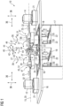
- FIG 1 a first embodiment of a claimed testing device 10 is shown schematically in a sectional view.
- the testing device 10 includes a drive unit 12, which is designed as an electric motor, and an output unit 14, which is designed as a generator.
- the drive unit 12 and the output unit 14 are each arranged on a base 21.
- a first and a second gear 20, 30, which are designed as wind turbine gears 47, are arranged between the drive unit 12 and the output unit 14.
- the first and second gears 20, 30 are of different types and are to be tested on the testing device 10.
- the drive unit 12 provides a mechanical drive power 25, which is delivered to the output unit 14 by the first and second gears 20, 30.
- the drive power 25 is generated about a main axis of rotation 15 of the first and second gears 20, 30, which represents a spatial axis 35 in the context of the testing device 10.
- the drive unit 12 is connected directly via a power shaft 32 to the first transmission 20 on its output side 29 in a torque-transmitting manner.
- the second transmission 30 is connected directly via a power shaft 32 to the output unit 14 on its output side 29 in a torque-transmitting manner.
- the first and second gears 20, 30 are connected to one another via a center bearing 34.
- the center bearing 34 is designed to connect shafts of the first and second gears 20, 30 in a torque-transmitting manner and to absorb radial forces relative to the main axis of rotation 15.
- the center bearing 34 is also connected to the environment, i.e. the floor level 16, via an actuator. Radial forces can be introduced into the first and second gears 20, 30 by the actuator 22.
- a flow of mechanical drive power 25 which is in FIG 1 is shown as an arrow, a speed is reduced in the first gear 20 and a speed is increased in the second gear.
- the first and second gears 20, 30 are each connected with their drive side 26 to the connecting flange 34, and thus in the opposite translation direction, i.e. the direction of the speed change.
- the first and second gears 20, 30 are each fastened on a test holder 24, which is each connected to a support frame 18, which is located essentially at ground level on a floor level 16.
- the support frame 18 is designed to be tiltable and/or displaceable, so that a mechanical reaction 40 can be specifically caused in the area of the center bearing 34.
- the support frames 18 are each attached to actuators 22, which are designed as hydraulic cylinders.
- the actuators 22 are each designed to exert an actuator force 33 and thus cause a tilting 27 and/or displacement 36 of the first and/or second transmission 20, 30. Such a tilt 27 and/or shifting 36 can take place about several spatial axes 35, as in FIG 1 shown.
- the mechanical reaction 40 includes reaction forces 42 in the area of the center bearing 34, which are oriented in different spatial directions.
- the mechanical reaction 40 also includes reaction torques 44, which have different orientations corresponding to the reaction forces 42.
- Actuation of the actuators 22 is adjustable, so that a tilting 27 and/or displacement 36 of the first and/or second transmission 20, 30 can be specifically caused.
- the mechanical reaction 40 that is caused in this way corresponds to a desired operating state of the first and second transmissions 20, 30 under which they are to be tested. Accordingly, reaction forces 42 and/or reaction torques 44 are present in the first and second transmissions 20, 30.
- a tilting 27 and/or displacement 36 of the first and/or second gear 20, 30 causes a mirror-inverted stress in both gears 20, 30.
- the mechanical reaction 40 i.e. the corresponding reaction forces 42 and reaction torques 44, can be detected via sensors 45, which are each arranged in the first and second gears 20, 30.
- the sensors 45 are attached to measuring points 51 in the first and second transmissions 20, 30. The test results achieved in this way are therefore directly comparable with one another for the first and second transmissions 20, 30.
- the actuators 22 are arranged on a foundation 17 which lies below the floor level 16.
- the foundation 17 serves as a base 19 and lies below the support frame 18 with the test holders 24 for the gears 20, 30.
- the actuators 22 are therefore essentially positioned in a cellar-like recess.
- the actuators 22 can be positioned close to one another, whereby the foundation 17 has a reduced size.
- Sufficiently resilient foundations 17 and also sufficiently resilient Socket 21 is complex and expensive.
- the testing device 10 requires smaller foundations 17 and bases 21 than solutions known from the prior art and can therefore be produced with reduced construction effort.
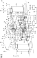
- FIG 2 shows schematically a second embodiment of the claimed testing device 10 in a partially sectioned oblique view.
- a person P is shown standing on a floor level 16.
- the testing device 10 comprises a drive unit 12 and an output unit 14, which are connected to each other in a torque-transmitting manner via a first and a second gear 20, 30.
- the gearboxes 20, 30 are designed as wind turbine gearboxes 47 and are of different types.
- the first and second transmissions 20, 30 are to be tested at least partially simultaneously in the testing device 10.
- the drive unit 12 is arranged on a base 21 and is designed as an electric motor through which mechanical drive power 25 is provided.
- the mechanical drive power 25, the flow direction of which is shown by the arrow 25, is transmitted directly to an output side 29 of the first transmission 20 via a power shaft 32.
- the mechanical drive power 25 has a torque that is oriented about a main axis of rotation 15 of the gears 20, 30 and corresponds to a spatial axis 35 in connection with the testing device 10.
- the first and second gears 20, 30 are connected to the center bearing 34 via their respective drive side 26.
- the speed is increased in the first gear 20 and the speed is reduced in the second gear 30.
- the first and second gears 20, 30 are connected to one another in opposite translation directions. This arrangement is also called back-to-back arrangement.
- the second gear 30 is also directly connected on its output side 29 via a power shaft 32 to the output unit 14, which is designed as a generator. Won with the one in the output unit 14
- the drive unit 12 can be operated at least partially using electrical energy.
- the output unit 14 is also positioned on a base 21, corresponding to the drive unit 12.
- the gears 20, 30 are attached to test holders 24, which are each arranged on a support frame 18.
- the support frames 18 in turn are movably accommodated on a plurality of actuators 22 and supports 28.
- the actuators 22, which are designed as hydraulic cylinders, are suitable for exerting an actuator force 33 through which the support frames 18 can be tilted and/or displaced.
- the actuators 22 are arranged on a base frame 39, which serves as a base 19 for the actuators 22.
- a tilting 27 and/or displacement 36 of the first and/or second gear 20, 30 around or along a spatial axis 35 can thus be caused by corresponding actuation of the actuators 22.
- a mechanical reaction 40 is caused in the first and second transmissions 20, 30 in a mirror image, which respectively includes reaction forces 42 and reaction torques 44.
- the reaction forces 42 and reaction torques 44 in the first and second transmissions 20, 30 are therefore essentially the same in mirror image at the same time.
- the first and second gears are therefore subject to the same mechanical stress.
- the corresponding states present at the same time therefore allow the testing of the first gearbox to be directly compared with the testing of the second gearbox.
- the test device as a whole and each of the transmissions 20, 30 are equipped with sensors 45 which are arranged at measuring points 51 (not shown) in the respective transmission 20, 30.
- the sensors 45 are designed to transmit measurement data 53 to a control unit 50.
- the control unit 50 includes an internal control unit 52, which is assigned directly to the testing device 10.
- the control unit 50 is also designed to issue control commands 55 to at least one of the actuators 22.
- the control unit 50 also includes a higher-level control unit 54, which is connected to the internal control unit 52 via a data connection 56.
- the higher-level control unit 54 can be designed, for example, as a computer cloud or master computer, which interacts with the internal control unit 52 for test operation.
- the internal control unit 52 and the higher-level control unit 54 each have a memory for storing and executing a computer program product 60, via which the testing device 10 can be operated. Through the computer program product 60, control commands 55 for the actuators 22 can be specified and/or measurement data 53 from the sensors 45 can be stored and/or processed.
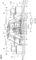
- FIG 3 A third embodiment of the claimed testing device 10 is shown schematically.
- the testing device 10 comprises a drive unit 12 and an output unit 14.
- the drive unit 12, which is designed as an electric motor, provides a mechanical drive power 25, which is supplied to a first gear 20 via a power shaft 32.
- the first gear 20 is connected via a center bearing 34 to a second gear 30, via which the mechanical drive power 25 is directly supplied to the output unit 14 by means of a power shaft 32, which is designed as a generator.
- the center bearing 34 is connected to the floor level 16 via at least one actuator 22 or via a passive connection.
- the first and second gears 20, 30 are each designed as wind turbine gears 47.
- the mechanical drive power 25 is transported in the testing device 10 in the arrow direction outlined along a main axis of rotation 15 of the gears 20, 30, which is to be understood as the spatial axis 35 in the testing device 10.
- the drive unit 12 and the output unit 14 are respectively positioned on a base 21, which stands on a floor level 16.
- the gears 20, 30 arranged in between are each fastened in a test holder 24, which can be tilted and displaced along or about several spatial axes 35.
- the experimental holder 24 is firmly connected to a support frame 18, which can be tilted about a joint 38 with the experimental holder 24.
- Tilting 27 and/or displacement 36 of the first and/or second gear 20, 30 can be achieved via actuators 22, which connect the test holders 24 of the first and second gear 20, 30 to one another.
- the actuators 22 are designed as hydraulic cylinders and are suitable for each exerting an actuator force 33.
- a mechanical reaction 40 can be caused in the area of the center bearing 34 in the first and second gear 20, 30, which includes reaction forces 42 and reaction torques 44.
- the mechanical reaction 40 is also determined by the radial forces exerted via the center bearing 36.
- the reaction forces 42 and reaction torques 44 correspond in mirror images in the first and second transmissions 20, 30.
- the mechanical reaction 40 can thus be specifically adjusted in both transmissions 20, 30, and thus a desired operating state of the transmissions 20, 30 can be adjusted in a test run.
- the experimental setups including the gears 20, 30 are equipped with sensors 45 which are positioned in or on the gears 20, 30 at measuring points 51 (not shown in detail).
- the sensors 45 can generate measurement data 53 which can be received by a control unit 50.
- the control unit 50 includes an internal control unit 52, which is assigned directly to the testing device 10.
- the control unit 50 has a memory and is equipped with a computer program product 60, which is designed to store and/or process the measurement data 53 from the sensors 45.
- the computer program product 60 is also designed to issue control commands 55 for actuating the actuators 22.
- the first and second gears 20, 30 are at least partially simultaneous testable and measurement data 53, which were generated at the same time, can be directly compared with one another. Overall, this allows test runs to be carried out particularly quickly and efficiently for direct comparison of the transmissions 20, 30.
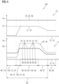
- FIG 4 shows schematically the sequence of an embodiment of the claimed method 100 for testing transmissions 20, 30 with a testing device 10.
- FIG 4 assumes that a first and second step 110, 120, in which the gears 20, 30 are mounted in the testing device 10 and the testing device 10 is activated, have been carried out.
- a first diagram 70 the course of a test run 75 is depicted along a horizontal time axis 72.
- the first diagram 70 also has a vertical size axis 74.
- a mechanical drive power 25 with which the gears 20, 30 are driven remains constant.
- stationary operation 48 occurs, in which the gears 20, 30 are aligned, that is, their main axes of rotation 15 are aligned.
- the first diagram 70 there is a tilting 27 by a tilting angle 37 of zero for the first and/or second transmission 20, 30.
- a mechanical reaction 40 occurs on the first and second gears 20, 30, as shown on a size axis 40 in a second diagram 71.
- the embodiment according to FIG 4 assumes that there is only a tilting 27 that causes mechanical reactions 40, but no displacement 36, as in FIG 1 to FIG 3 sketched.
- the mechanical reaction 40 includes at least one reaction force 42 and at least one reaction torque 44, which are essentially constant during steady-state operation 48.
- the at least one reaction force 42 and the at least one reaction torque 44 result essentially as supporting reactions of the gears 20, 30 in the respective test holders 24.
- the stationary operation 48 in the second step 120 is followed in a third step 130 by a transitional operation 49 in which at least the tilt angle 37 is increased.
- at least one actuator 22 of the testing device 10 is actuated via a control unit 50, which results in a tilting 27 of the first and/or second transmission 20, 30.
- the at least one reaction torque 44 and the at least one reaction force 42 increase and reach a substantially constant amount in a fourth step 140.
- a desired operating state is achieved by tilting 27, which is to be measured as part of the test run.
- a measuring operation 58 takes place in the third step 130, in which measurement data 53 is generated by means of sensors 45 which are attached to measuring points 51 in the gears 20, 30, on an actuator 22, a test holder 24 and/or a support frame 18.
- the measurement data 53 are shown in the second diagram 71 as an example as measuring points 41, which are to be transmitted to a control unit 50 of the testing device 10.
- Each of the measuring points 41 has a unique position on the time axis 72, which is shown as a time stamp 59.
- measurement data 53 for the first and second transmissions 20, 30, i.e. the operating state present at this point in time can be directly compared with one another.
- the fourth step 140 is followed by a further transition operation 49, in which the tilt angle 37 is reduced. Accordingly, the at least one reaction force 42 and the at least one reaction torque 44 adjust to a reduced amount.
- This is followed by another stationary operation 48, which can also be used as a measuring operation 58.
- Several runs of individual or all outlined steps 110, 120, 130, 140 can be combined to form a test run 75 with increased complexity.
- the control unit 50 is suitable for specifying the actuation of actuators 22 using control commands 55 and/or for storing and/or evaluating the measurement data 53 from the test run 75.
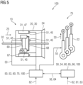
- FIG 5 A section of the claimed testing device 10 is shown schematically.
- FIG 5 shows one of the two transmissions 20, 30, which is carried out using the testing device 10 according to the embodiments of Figures 1-3 are to be tested.
- the gears 20, 30 are designed as planetary gears 31, in particular as wind turbine gears 47.
- a ring gear 67, a planetary gear carrier 68 and a sun gear 69 are each provided with a sensor 45.
- the sensors 45 are designed to detect a strain, a force, a temperature and/or a vibration and are each arranged at a measuring point 51.
- a mechanical drive power 25 is supplied via a power shaft 32, which is coupled to the sun gear 69 in a torque-transmitting manner.
- the transmission 20, 30 is connected to another transmission, not shown, via a center bearing 34.
- Each of the sensors 45 is coupled to an internal control unit 52, which belongs to a control unit 50, for transmitting measurement data 53.
- the internal control unit 52 is suitable for receiving a user input 62, through which a test run 75 for the testing device 10 can be set in a computer program product 60, which is stored executably in the control unit 50.
- the computer program product 60 uses the computer program product 60, the in FIG 4 described method 100 can be carried out.
- the internal control unit 52 and the computer program product 60 are designed to issue control commands 55 to at least one actuator 22, through which an actuator force 33 to be exerted can be specified. This makes it possible to set a desired test run 75.
- the internal control unit 52 is coupled to a higher-level control unit 54 via a data connection 56.
- the data connection 56 is designed as an Internet connection 64 and the higher-level control unit 54 as a computer cloud 65.
- the computer cloud 65 there is a so-called digital twin 66, also digital Called Twin, so a simulation image of at least one Transmission 20, 30 stored in connection with the testing device 10.
- a computer program product 60 is also stored on the higher-level control unit 54, which interacts with the computer program product 60 in the internal control unit 52 via the data connection 56 and follows the method 100 FIG 4 to implement.
- the higher-level control unit 54 is also designed to receive a user input 62, through which a test run 75 can be set. For example, a test force 61 and/or a test torque 63 can be specified by the user input 62, which is to be implemented by the reaction force 42 or the reaction torque 44 on the respective transmission 20, 30.
Landscapes
- Physics & Mathematics (AREA)
- General Physics & Mathematics (AREA)
- Testing Of Devices, Machine Parts, Or Other Structures Thereof (AREA)
Claims (11)
- Dispositif d'essai (10) pour mécanismes d'engrenage (20, 30), le dispositif d'essai comprenantun premier mécanisme d'engrenage (20) réalisé en tant que mécanisme d'engrenage planétaire, etun deuxième mécanisme d'engrenage (30) réalisé en tant que mécanisme d'engrenage planétaire, dans lequel une couronne (67), un porte-satellites (68) et une roue solaire (69) des mécanismes d'engrenage (20, 30) sont munis d'un capteur (45) respectivement,une unité d'entraînement (12) et une unité de sortie (14) qui sont reliées l'une à l'autre par l'intermédiaire du premier et du deuxième mécanisme d'engrenage (20, 30) et de paliers centraux (34) reliant les deux mécanismes d'engrenage (20, 30) l'un à l'autre,dans lequel les mécanismes d'engrenage (20, 30) sont respectivement fixés à un support d'essai (24), et chaque support d'essai (24) est relié à un cadre porteur (18) se trouvant au niveau du sol sur un plan de sol (16), et les cadres porteurs (18) sont respectivement fixés à des actionneurs (22), etpour un essai au moins partiellement simultané du premier et du deuxième mécanisme d'engrenage (20, 30), les actionneurs (22) exercent une force d'actionneur (33) afin de provoquer un basculement (27) et/ou un décalage (36) autour de plusieurs axes spatiaux (35) en tant que réaction mécanique (40) au moins du premier mécanisme d'engrenage (20),dans lequel la réaction mécanique (40), qui présente des forces de réaction (42) et des couples de réaction (44) au niveau du palier central (34), est détectée par les capteurs (45).
- Dispositif d'essai (10) selon la revendication 1, caractérisé en ce que le premier et le deuxième mécanisme d'engrenage (20, 30) sont reliés l'un à l'autre dans une direction de rapport de transmission opposée.
- Dispositif d'essai (10) selon la revendication 1 ou 2, caractérisé en ce que ledit au moins un actionneur (22) est fixé au support (19).
- Dispositif d'essai (10) selon l'une quelconque des revendications 1 à 3, caractérisé en ce que l'actionneur (22) est disposé au-dessous d'un plan de sol (16).
- Dispositif d'essai (10) selon l'une quelconque des revendications 1 à 4, caractérisé en ce que le premier ou le deuxième mécanisme d'engrenage (20, 30) est relié directement en transmission de couple à l'unité d'entraînement (12) ou à l'unité de sortie (14).
- Dispositif d'essai (10) selon l'une quelconque des revendications 1 à 5, caractérisé en ce que le premier et/ou le deuxième mécanisme d'engrenage (20, 30) sont réalisés sous forme de mécanismes d'engrenage d'éolienne (47).
- Dispositif d'essai (10) selon l'une quelconque des revendications 1 à 6, caractérisé en ce qu'une unité de commande (50) est associée au dispositif d'essai (10) pour régler le basculement (27) au moins du premier mécanisme d'engrenage (20).
- Procédé (100) permettant d'essayer des mécanismes d'engrenage (20, 30), comprenant les étapes consistant à :a) fournir un premier et un deuxième mécanisme d'engrenage (20, 30) dans un dispositif d'essai (10) réalisé selon l'une quelconque des revendications précédentes ;b) activer l'unité d'entraînement (12) du dispositif d'essai (10) ;c) basculer (27) et/ou décaler (36) de manière réglable au moins le premier mécanisme d'engrenage (20, 30) au moyen des actionneurs (22) du dispositif d'essai (10) afin de produire une force de réaction (42) et/ou un couple de réaction (44) entre le premier et le deuxième mécanisme d'engrenage (20, 30) ;dans lequel la force de réaction (42) et/ou le couple de réaction (44) correspondent à une force d'essai (61) ou à un couple d'essai (63) qui font partie d'une marche d'essai conforme (75).
- Procédé (100) selon la revendication 8, caractérisé en ce que l'essai du premier et du deuxième mécanisme d'engrenage (20, 30) est effectué au moins partiellement en même temps.
- Produit de programme informatique (60) permettant de régler des forces d'essai (61) et/ou des couples d'essai (63) pour essayer des mécanismes d'engrenage (20, 30) au cours d'une marche d'essai (75) et d'émettre des instructions de commande (55) d'un dispositif d'essai (10) selon l'une quelconque des revendications 1 à 7 pour exécuter un procédé selon l'une quelconque des revendications 8 ou 9.
- Unité de commande (50) permettant d'émettre des instructions d'actionnement pour au moins un actionneur (22) d'un dispositif d'essai (10), dans lequel l'unité de commande (50) comprend une mémoire et une unité de calcul, dans laquelle un produit de programme informatique selon la revendication 10 est stocké sur l'unité de commande (10).
Applications Claiming Priority (2)
| Application Number | Priority Date | Filing Date | Title |
|---|---|---|---|
| EP20154842.7A EP3859297A1 (fr) | 2020-01-31 | 2020-01-31 | Dispositif d'essai pour transmissions, procédure d'essai, unité de commande et produit programme informatique |
| PCT/EP2021/050327 WO2021151635A1 (fr) | 2020-01-31 | 2021-01-11 | Dispositif de test pour mécanismes d'engrenage, procédé de test, unité de commande et produit programme d'ordinateur |
Publications (2)
| Publication Number | Publication Date |
|---|---|
| EP4097441A1 EP4097441A1 (fr) | 2022-12-07 |
| EP4097441B1 true EP4097441B1 (fr) | 2024-01-10 |
Family
ID=69423144
Family Applications (2)
| Application Number | Title | Priority Date | Filing Date |
|---|---|---|---|
| EP20154842.7A Pending EP3859297A1 (fr) | 2020-01-31 | 2020-01-31 | Dispositif d'essai pour transmissions, procédure d'essai, unité de commande et produit programme informatique |
| EP21701892.8A Active EP4097441B1 (fr) | 2020-01-31 | 2021-01-11 | Dispositif d'essai pour transmissions, procédure d'essai, unité de commande et produit programme informatique |
Family Applications Before (1)
| Application Number | Title | Priority Date | Filing Date |
|---|---|---|---|
| EP20154842.7A Pending EP3859297A1 (fr) | 2020-01-31 | 2020-01-31 | Dispositif d'essai pour transmissions, procédure d'essai, unité de commande et produit programme informatique |
Country Status (5)
| Country | Link |
|---|---|
| US (1) | US20230047604A1 (fr) |
| EP (2) | EP3859297A1 (fr) |
| CN (1) | CN115038950A (fr) |
| DK (1) | DK4097441T3 (fr) |
| WO (1) | WO2021151635A1 (fr) |
Families Citing this family (1)
| Publication number | Priority date | Publication date | Assignee | Title |
|---|---|---|---|---|
| CN113942681B (zh) * | 2021-12-20 | 2022-03-18 | 常州市沃凯轴承制造有限公司 | 一种传动部件包装装置 |
Citations (1)
| Publication number | Priority date | Publication date | Assignee | Title |
|---|---|---|---|---|
| DE102015221683A1 (de) * | 2015-11-05 | 2017-05-11 | Zf Friedrichshafen Ag | Getriebeprüfstand mit spezieller Verspannung |
Family Cites Families (5)
| Publication number | Priority date | Publication date | Assignee | Title |
|---|---|---|---|---|
| US3580068A (en) * | 1968-08-26 | 1971-05-25 | Louis S Hoodwin | Apparatus for testing rotary power transmitting components |
| DE102010053808A1 (de) | 2010-12-08 | 2012-06-14 | Robert Bosch Gmbh | Windkraftgetriebeprüfstand |
| EP2574778B1 (fr) | 2011-09-29 | 2015-09-09 | Moventas Gears Oy | Banc d'essai et procédé de test de boîtes de vitesses et convertisseurs d'énergie électro-mécaniques |
| WO2013060475A1 (fr) * | 2011-10-27 | 2013-05-02 | Robert Bosch Gmbh | Banc d'essai de boîte de vitesses et procédé de fonctionnement d'un banc d'essai de boîte de vitesses |
| CN106226075B (zh) * | 2016-09-23 | 2018-07-03 | 四川大学 | 高低温齿轮传动综合性能实验台 |
-
2020
- 2020-01-31 EP EP20154842.7A patent/EP3859297A1/fr active Pending
-
2021
- 2021-01-11 EP EP21701892.8A patent/EP4097441B1/fr active Active
- 2021-01-11 DK DK21701892.8T patent/DK4097441T3/da active
- 2021-01-11 WO PCT/EP2021/050327 patent/WO2021151635A1/fr active Search and Examination
- 2021-01-11 US US17/796,546 patent/US20230047604A1/en active Pending
- 2021-01-11 CN CN202180011718.9A patent/CN115038950A/zh active Pending
Patent Citations (1)
| Publication number | Priority date | Publication date | Assignee | Title |
|---|---|---|---|---|
| DE102015221683A1 (de) * | 2015-11-05 | 2017-05-11 | Zf Friedrichshafen Ag | Getriebeprüfstand mit spezieller Verspannung |
Also Published As
| Publication number | Publication date |
|---|---|
| EP4097441A1 (fr) | 2022-12-07 |
| US20230047604A1 (en) | 2023-02-16 |
| WO2021151635A1 (fr) | 2021-08-05 |
| CN115038950A (zh) | 2022-09-09 |
| EP3859297A1 (fr) | 2021-08-04 |
| DK4097441T3 (da) | 2024-04-02 |
Similar Documents
| Publication | Publication Date | Title |
|---|---|---|
| EP1659286B1 (fr) | Vireur pour axe de générateur entraîné par une éolienne | |
| EP0874715B1 (fr) | Dispositif pour des appareils de fabrication, manipulation ou mesure a commande numerique | |
| DE69823123T2 (de) | Modulare Parallelantriebseinheit | |
| DE3642717A1 (de) | Verfahren zum pruefen von antriebsachsen und vorrichtung zur durchfuehrung des verfahrens | |
| EP0895585B1 (fr) | Banc d'essai de contrainte pour un engrenage d'helicoptere | |
| DE102010040654A1 (de) | Demontage eines Getriebes einer Windenergieanlage | |
| EP1677032A1 (fr) | Méthode pour remplacer les satellites | |
| EP4097441B1 (fr) | Dispositif d'essai pour transmissions, procédure d'essai, unité de commande et produit programme informatique | |
| EP3548859A1 (fr) | Banc d'essai de chaîne cinématique pouvant être construit de façon modulaire, destiné à des propulsions électriques de véhicules à moteur | |
| CN106840644A (zh) | 电磁与电动推杆混合加载刀架可靠性试验台 | |
| WO2005087424A1 (fr) | Dispositif de soudage par friction à rotation | |
| DE102014115241A1 (de) | Pressenantriebsvorrichtung für eine Presse und Presse mit Pressenantriebsvorrichtung | |
| DE19810406A1 (de) | Exzenterpresse mit variabler Stößelbewegung | |
| DE10316249A1 (de) | Verfahren zum Umformen eines Werkstückes und Walzmaschine | |
| EP2495473A1 (fr) | Engrenage adaptatif | |
| DE4325403A1 (de) | Verspannungsprüfstand | |
| EP4363172A2 (fr) | Robot industriel doté d'un entraînement d'essieu monté de manière compacte | |
| EP4298420A1 (fr) | Support de couple central pour un test de transmission planétaire avec supports de couple | |
| EP4295134B1 (fr) | Essai des engrenages planétaires sans paliers de carrière planétaire | |
| CN206930431U (zh) | 电磁与电动推杆混合加载刀架可靠性试验台 | |
| EP3242013A1 (fr) | Éolienne comprenant un dispositif destine a faire tourner une nacelle de l'eolienne et procede de montage d'un dispositif destine a faire tourner une nacelle | |
| DE69812861T2 (de) | Walzwerk zur herstellung von axialsymmetrischen teilen | |
| DE102017205604B4 (de) | Verfahren zum Prüfen von Großlagern für Windenergieanlagen, Lageranordnung und Prüfstand | |
| AT516367B1 (de) | Prüfstand und Prüfverfahren mit verstellbarem Achsabstand zwischen Übertragungsprüfkörpern | |
| EP3609648A1 (fr) | Procédé et dispositif de trempe par impact des rayons de transition d'un vilebrequin |
Legal Events
| Date | Code | Title | Description |
|---|---|---|---|
| STAA | Information on the status of an ep patent application or granted ep patent |
Free format text: STATUS: UNKNOWN |
|
| STAA | Information on the status of an ep patent application or granted ep patent |
Free format text: STATUS: THE INTERNATIONAL PUBLICATION HAS BEEN MADE |
|
| PUAI | Public reference made under article 153(3) epc to a published international application that has entered the european phase |
Free format text: ORIGINAL CODE: 0009012 |
|
| STAA | Information on the status of an ep patent application or granted ep patent |
Free format text: STATUS: REQUEST FOR EXAMINATION WAS MADE |
|
| 17P | Request for examination filed |
Effective date: 20220809 |
|
| AK | Designated contracting states |
Kind code of ref document: A1 Designated state(s): AL AT BE BG CH CY CZ DE DK EE ES FI FR GB GR HR HU IE IS IT LI LT LU LV MC MK MT NL NO PL PT RO RS SE SI SK SM TR |
|
| DAV | Request for validation of the european patent (deleted) | ||
| DAX | Request for extension of the european patent (deleted) | ||
| GRAP | Despatch of communication of intention to grant a patent |
Free format text: ORIGINAL CODE: EPIDOSNIGR1 |
|
| STAA | Information on the status of an ep patent application or granted ep patent |
Free format text: STATUS: GRANT OF PATENT IS INTENDED |
|
| INTG | Intention to grant announced |
Effective date: 20231002 |
|
| GRAS | Grant fee paid |
Free format text: ORIGINAL CODE: EPIDOSNIGR3 |
|
| GRAA | (expected) grant |
Free format text: ORIGINAL CODE: 0009210 |
|
| STAA | Information on the status of an ep patent application or granted ep patent |
Free format text: STATUS: THE PATENT HAS BEEN GRANTED |
|
| AK | Designated contracting states |
Kind code of ref document: B1 Designated state(s): AL AT BE BG CH CY CZ DE DK EE ES FI FR GB GR HR HU IE IS IT LI LT LU LV MC MK MT NL NO PL PT RO RS SE SI SK SM TR |
|
| REG | Reference to a national code |
Ref country code: GB Ref legal event code: FG4D Free format text: NOT ENGLISH |
|
| REG | Reference to a national code |
Ref country code: CH Ref legal event code: EP |
|
| REG | Reference to a national code |
Ref country code: DE Ref legal event code: R096 Ref document number: 502021002424 Country of ref document: DE |
|
| REG | Reference to a national code |
Ref country code: IE Ref legal event code: FG4D Free format text: LANGUAGE OF EP DOCUMENT: GERMAN |
|
| REG | Reference to a national code |
Ref country code: DE Ref legal event code: R081 Ref document number: 502021002424 Country of ref document: DE Owner name: VESTAS WIND SYSTEMS A/S, DK Free format text: FORMER OWNER: FLENDER GMBH, 46395 BOCHOLT, DE Ref country code: DE Ref legal event code: R081 Ref document number: 502021002424 Country of ref document: DE Owner name: FLENDER GMBH, DE Free format text: FORMER OWNER: FLENDER GMBH, 46395 BOCHOLT, DE |
|
| REG | Reference to a national code |
Ref country code: DK Ref legal event code: T3 Effective date: 20240325 |
|
| RAP2 | Party data changed (patent owner data changed or rights of a patent transferred) |
Owner name: VESTAS WIND SYSTEMS A/S Owner name: FLENDER GMBH |
|
| REG | Reference to a national code |
Ref country code: GB Ref legal event code: 732E Free format text: REGISTERED BETWEEN 20240307 AND 20240313 |
|
| REG | Reference to a national code |
Ref country code: BE Ref legal event code: PD Owner name: FLENDER GMBH; DE Free format text: DETAILS ASSIGNMENT: CHANGE OF OWNER(S), ASSIGNMENT Effective date: 20240306 |
|
| PGFP | Annual fee paid to national office [announced via postgrant information from national office to epo] |
Ref country code: DE Payment date: 20240327 Year of fee payment: 4 |
|
| REG | Reference to a national code |
Ref country code: LT Ref legal event code: MG9D |
|
| REG | Reference to a national code |
Ref country code: NL Ref legal event code: MP Effective date: 20240110 |