EP3859249A1 - Refrigerant leakage determination device, freezing device including this refrigerant leakage determination device, and refrigerant leakage determination method - Google Patents
Refrigerant leakage determination device, freezing device including this refrigerant leakage determination device, and refrigerant leakage determination method Download PDFInfo
- Publication number
- EP3859249A1 EP3859249A1 EP19865774.4A EP19865774A EP3859249A1 EP 3859249 A1 EP3859249 A1 EP 3859249A1 EP 19865774 A EP19865774 A EP 19865774A EP 3859249 A1 EP3859249 A1 EP 3859249A1
- Authority
- EP
- European Patent Office
- Prior art keywords
- refrigerant
- refrigeration apparatus
- compressor
- index value
- refrigerant leakage
- Prior art date
- Legal status (The legal status is an assumption and is not a legal conclusion. Google has not performed a legal analysis and makes no representation as to the accuracy of the status listed.)
- Granted
Links
- 239000003507 refrigerant Substances 0.000 title claims abstract description 483
- 238000000034 method Methods 0.000 title claims description 23
- 230000008014 freezing Effects 0.000 title 1
- 238000007710 freezing Methods 0.000 title 1
- 238000005057 refrigeration Methods 0.000 claims abstract description 175
- 238000004364 calculation method Methods 0.000 claims abstract description 4
- 230000009849 deactivation Effects 0.000 claims description 14
- 230000004913 activation Effects 0.000 claims description 13
- 238000007689 inspection Methods 0.000 claims description 13
- 238000009833 condensation Methods 0.000 claims description 11
- 230000005494 condensation Effects 0.000 claims description 11
- 238000001704 evaporation Methods 0.000 claims description 11
- 230000008020 evaporation Effects 0.000 claims description 11
- 230000006837 decompression Effects 0.000 claims description 10
- 238000000611 regression analysis Methods 0.000 claims description 5
- 239000007788 liquid Substances 0.000 description 25
- 238000013500 data storage Methods 0.000 description 15
- 230000000875 corresponding effect Effects 0.000 description 13
- 238000001816 cooling Methods 0.000 description 11
- 238000007781 pre-processing Methods 0.000 description 10
- 239000000284 extract Substances 0.000 description 9
- 230000008569 process Effects 0.000 description 8
- 230000008859 change Effects 0.000 description 7
- 238000010257 thawing Methods 0.000 description 7
- 230000005856 abnormality Effects 0.000 description 6
- 230000006835 compression Effects 0.000 description 6
- 238000007906 compression Methods 0.000 description 6
- 238000004781 supercooling Methods 0.000 description 6
- 238000001514 detection method Methods 0.000 description 5
- 230000004308 accommodation Effects 0.000 description 4
- 238000010586 diagram Methods 0.000 description 4
- 230000007246 mechanism Effects 0.000 description 4
- 238000002474 experimental method Methods 0.000 description 3
- 238000010438 heat treatment Methods 0.000 description 3
- 238000012546 transfer Methods 0.000 description 3
- XLYOFNOQVPJJNP-UHFFFAOYSA-N water Substances O XLYOFNOQVPJJNP-UHFFFAOYSA-N 0.000 description 3
- 230000007423 decrease Effects 0.000 description 2
- 238000000605 extraction Methods 0.000 description 2
- 238000009434 installation Methods 0.000 description 2
- 238000012545 processing Methods 0.000 description 2
- 238000005070 sampling Methods 0.000 description 2
- 230000002596 correlated effect Effects 0.000 description 1
- 230000003247 decreasing effect Effects 0.000 description 1
- 238000006073 displacement reaction Methods 0.000 description 1
- 238000010295 mobile communication Methods 0.000 description 1
- 239000007787 solid Substances 0.000 description 1
- 239000013526 supercooled liquid Substances 0.000 description 1
Images


Classifications
-
- F—MECHANICAL ENGINEERING; LIGHTING; HEATING; WEAPONS; BLASTING
- F25—REFRIGERATION OR COOLING; COMBINED HEATING AND REFRIGERATION SYSTEMS; HEAT PUMP SYSTEMS; MANUFACTURE OR STORAGE OF ICE; LIQUEFACTION SOLIDIFICATION OF GASES
- F25B—REFRIGERATION MACHINES, PLANTS OR SYSTEMS; COMBINED HEATING AND REFRIGERATION SYSTEMS; HEAT PUMP SYSTEMS
- F25B49/00—Arrangement or mounting of control or safety devices
- F25B49/005—Arrangement or mounting of control or safety devices of safety devices
-
- F—MECHANICAL ENGINEERING; LIGHTING; HEATING; WEAPONS; BLASTING
- F25—REFRIGERATION OR COOLING; COMBINED HEATING AND REFRIGERATION SYSTEMS; HEAT PUMP SYSTEMS; MANUFACTURE OR STORAGE OF ICE; LIQUEFACTION SOLIDIFICATION OF GASES
- F25B—REFRIGERATION MACHINES, PLANTS OR SYSTEMS; COMBINED HEATING AND REFRIGERATION SYSTEMS; HEAT PUMP SYSTEMS
- F25B49/00—Arrangement or mounting of control or safety devices
- F25B49/02—Arrangement or mounting of control or safety devices for compression type machines, plants or systems
-
- F—MECHANICAL ENGINEERING; LIGHTING; HEATING; WEAPONS; BLASTING
- F25—REFRIGERATION OR COOLING; COMBINED HEATING AND REFRIGERATION SYSTEMS; HEAT PUMP SYSTEMS; MANUFACTURE OR STORAGE OF ICE; LIQUEFACTION SOLIDIFICATION OF GASES
- F25B—REFRIGERATION MACHINES, PLANTS OR SYSTEMS; COMBINED HEATING AND REFRIGERATION SYSTEMS; HEAT PUMP SYSTEMS
- F25B40/00—Subcoolers, desuperheaters or superheaters
-
- F—MECHANICAL ENGINEERING; LIGHTING; HEATING; WEAPONS; BLASTING
- F25—REFRIGERATION OR COOLING; COMBINED HEATING AND REFRIGERATION SYSTEMS; HEAT PUMP SYSTEMS; MANUFACTURE OR STORAGE OF ICE; LIQUEFACTION SOLIDIFICATION OF GASES
- F25B—REFRIGERATION MACHINES, PLANTS OR SYSTEMS; COMBINED HEATING AND REFRIGERATION SYSTEMS; HEAT PUMP SYSTEMS
- F25B41/00—Fluid-circulation arrangements
- F25B41/20—Disposition of valves, e.g. of on-off valves or flow control valves
-
- F—MECHANICAL ENGINEERING; LIGHTING; HEATING; WEAPONS; BLASTING
- F25—REFRIGERATION OR COOLING; COMBINED HEATING AND REFRIGERATION SYSTEMS; HEAT PUMP SYSTEMS; MANUFACTURE OR STORAGE OF ICE; LIQUEFACTION SOLIDIFICATION OF GASES
- F25B—REFRIGERATION MACHINES, PLANTS OR SYSTEMS; COMBINED HEATING AND REFRIGERATION SYSTEMS; HEAT PUMP SYSTEMS
- F25B2400/00—General features or devices for refrigeration machines, plants or systems, combined heating and refrigeration systems or heat-pump systems, i.e. not limited to a particular subgroup of F25B
- F25B2400/13—Economisers
-
- F—MECHANICAL ENGINEERING; LIGHTING; HEATING; WEAPONS; BLASTING
- F25—REFRIGERATION OR COOLING; COMBINED HEATING AND REFRIGERATION SYSTEMS; HEAT PUMP SYSTEMS; MANUFACTURE OR STORAGE OF ICE; LIQUEFACTION SOLIDIFICATION OF GASES
- F25B—REFRIGERATION MACHINES, PLANTS OR SYSTEMS; COMBINED HEATING AND REFRIGERATION SYSTEMS; HEAT PUMP SYSTEMS
- F25B2500/00—Problems to be solved
- F25B2500/19—Calculation of parameters
-
- F—MECHANICAL ENGINEERING; LIGHTING; HEATING; WEAPONS; BLASTING
- F25—REFRIGERATION OR COOLING; COMBINED HEATING AND REFRIGERATION SYSTEMS; HEAT PUMP SYSTEMS; MANUFACTURE OR STORAGE OF ICE; LIQUEFACTION SOLIDIFICATION OF GASES
- F25B—REFRIGERATION MACHINES, PLANTS OR SYSTEMS; COMBINED HEATING AND REFRIGERATION SYSTEMS; HEAT PUMP SYSTEMS
- F25B2500/00—Problems to be solved
- F25B2500/22—Preventing, detecting or repairing leaks of refrigeration fluids
- F25B2500/222—Detecting refrigerant leaks
-
- F—MECHANICAL ENGINEERING; LIGHTING; HEATING; WEAPONS; BLASTING
- F25—REFRIGERATION OR COOLING; COMBINED HEATING AND REFRIGERATION SYSTEMS; HEAT PUMP SYSTEMS; MANUFACTURE OR STORAGE OF ICE; LIQUEFACTION SOLIDIFICATION OF GASES
- F25B—REFRIGERATION MACHINES, PLANTS OR SYSTEMS; COMBINED HEATING AND REFRIGERATION SYSTEMS; HEAT PUMP SYSTEMS
- F25B2700/00—Sensing or detecting of parameters; Sensors therefor
- F25B2700/21—Temperatures
- F25B2700/2115—Temperatures of a compressor or the drive means therefor
- F25B2700/21152—Temperatures of a compressor or the drive means therefor at the discharge side of the compressor
Definitions
- the present disclosure relates to a refrigerant leakage determination device, a refrigeration apparatus including the refrigerant leakage determination device, and a method for determining refrigerant leakage.
- a typical air conditioner includes a refrigeration cycle in which an outdoor unit including a compressor is connected to an indoor unit by a refrigerant pipe.
- the air conditioner has a configuration that determines whether a refrigerant has leaked (refer to, for example, Patent Document 1).
- whether the refrigerant has leaked is determined by comparing an outside temperature when the compressor is activated at an initial stage after installation of the air conditioner, a discharge side temperature of the compressor when the air conditioner is operated under a predetermined condition, an outside temperature when the compressor is activated later, and a discharge side temperature of the compressor when the air conditioner is operated in the same predetermined condition.
- Patent Document 1 Japanese Laid-Open Patent Publication No. 2013-204871
- the operation condition of the air conditioner at the initial stage after installation of the air conditioner needs to conform to a later operation condition of the air conditioner. Therefore, a special operation for determining whether the refrigerant has leaked needs to be performed. In this configuration, the air conditioner cannot perform a normal operation while determining whether the refrigerant has leaked. This drawback is not limited to an air conditioner and also occurs in any refrigeration apparatus including a refrigerant circuit.
- a refrigerant leakage determination device determines a refrigerant leakage of a refrigeration apparatus (1).
- the refrigeration apparatus (1) includes a refrigerant circuit (20).
- the refrigerant circuit (20) includes a compressor, a condenser, a decompression device, and an evaporator and is configured so that a refrigerant circulates through the compressor, the condenser, the decompression device, and the evaporator.
- the refrigerant leakage determination device includes a calculator and a determination unit. The calculator calculates a deviation degree of the refrigerant circuit from a normal state based on data related to operation of the refrigeration apparatus.
- the determination unit determines whether the refrigerant has leaked or estimates a refrigerant leakage occurrence time based on a calculation result of the calculator.
- the data related to operation of the refrigeration apparatus include data related to operation of the refrigeration apparatus in a first period and data related to operation of the refrigeration apparatus in a second period that differs in length from the first period.
- the calculator is configured to calculate a first index value from the data related to operation of the refrigeration apparatus in the first period and calculate a second index value from the data related to operation of the refrigeration apparatus in the second period.
- the calculator is configured to calculate the deviation degree of the refrigerant circuit from the normal state based on the first index value and the second index value.
- the determination unit is configured to determine whether the refrigerant has leaked or estimate the refrigerant leakage occurrence time based on the deviation degree of the refrigerant circuit from the normal state.
- the deviation degree of the refrigerant circuit from the normal state is calculated based on the deviation degree between the first index value and the second index value that are calculated using data related to operation of the refrigeration apparatus including operation of the refrigeration apparatus in the pre-trip inspection and normal operations of the refrigeration apparatus.
- the data related to operation of the refrigeration apparatus is obtained from, for example, operations including normal operations of the refrigeration apparatus and a pre-trip inspection operation of the refrigeration apparatus.
- a refrigerant leakage determination method determines a refrigerant leakage of a refrigeration apparatus (1).
- the refrigeration apparatus (1) includes a refrigerant circuit (20).
- the refrigerant circuit (20) includes a compressor, a condenser, a decompression device, and an evaporator and is configured so that a refrigerant circulates through the compressor, the condenser, the decompression device, and the evaporator.
- the refrigerant leakage determination method includes storing data related to operation of the refrigeration apparatus.
- the refrigerant leakage determination method further includes calculating a first index value from data related to operation of the refrigeration apparatus in a first period and calculating a second index value from data related to operation of the refrigeration apparatus in a second period that differs in length from the first period.
- the refrigerant leakage determination method further includes calculating a deviation degree of the refrigerant circuit from a normal state based on the first index value and the second index value.
- the refrigerant leakage determination method further includes determining whether the refrigerant has leaked or estimating a refrigerant leakage occurrence time based on the deviation degree of the refrigerant circuit from the normal state.
- the deviation degree of the refrigerant circuit from the normal state is calculated based on the deviation degree between the first index value and the second index value that are calculated using data related to operation of the refrigeration apparatus including operation of the refrigeration apparatus in the pre-trip inspection and normal operations of the refrigeration apparatus.
- the data related to operation of the refrigeration apparatus is obtained from, for example, operations including normal operations of the refrigeration apparatus and a pre-trip inspection operation of the refrigeration apparatus.
- the refrigeration apparatus 1 is configured to refrigerate the inside of storage, for example, a shipping container or a road transportation trailer container.
- the inside of a casing of the refrigeration apparatus 1 is divided into an interior accommodation space that circulates the air in the storage and an exterior accommodation space that circulates the air outside the storage.
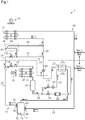
- the refrigeration apparatus 1 includes a refrigerant circuit 20 in which, for example, a compressor 11, a condenser 12, and an evaporator 13 are connected by a refrigerant pipe.
- the refrigerant circuit 20 includes a main circuit 21, a hot gas bypass circuit 22, and a liquid refrigerant bypass circuit 31.
- the compressor 11 that is motor-driven, the condenser 12, a first expansion valve 14Athat is an example of a decompression device, and the evaporator 13 are sequentially connected in series by the refrigerant pipe.
- the exterior accommodation space accommodates the compressor 11, the condenser 12, the first expansion valve 14A, and an exterior fan 15 that circulates the air outside the storage to the condenser 12.
- the interior accommodation space accommodates the evaporator 13 and an interior fan 16 that circulates the air in the storage to the evaporator 13.
- the compressor 11 may be, for example, a rotary compressor or a scroll compressor.
- the compressor 11 is configured so that the operating capacity is variable when an inverter controls the operating frequency to control the rotational speed.
- the condenser 12 and the evaporator 13 may be a fin-and-tube heat exchanger.
- the condenser 12 exchanges heat between the air outside the storage supplied by the exterior fan 15 and the refrigerant circulating in the condenser 12.
- the evaporator 13 exchanges heat between the air in the storage supplied by the interior fan 16 and the refrigerant circulating in the evaporator 13.
- An example of the exterior fan 15 and the interior fan 16 is a propeller fan.
- a drain pan 28 is disposed below the evaporator 13. The drain pan 28 collects, for example, frost and ice blocks falling from the evaporator 13 and water condensed from the air.
- the first expansion valve 14A may be, for example, an electric expansion valve having an opening degree that is variable using a pulse motor.
- the compressor 11 and the condenser 12 are connected by a high pressure gas pipe 23 that includes a first opening-closing valve 17Aand a check valve 18 sequentially arranged in a direction in which the refrigerant flows.
- the first opening-closing valve 17A may be, for example, an electric expansion valve having an opening degree that is variable using a pulse motor.
- the check valve 18 allows the refrigerant to flow in the directions of the arrows shown in Fig. 1 .
- the condenser 12 and the first expansion valve 14A are connected by a high pressure liquid pipe 24 that includes a receiver 29, a second opening-closing valve 17B, a dryer 30, and a supercooling heat exchanger 27 sequentially arranged in the direction in which the refrigerant flows.
- the second opening-closing valve 17B may be, for example, an electromagnetic valve capable of opening and closing.
- the supercooling heat exchanger 27 includes a primary passage 27a and a secondary passage 27b configured to exchange heat with each other.
- the primary passage 27a is disposed in the main circuit 21 between the dryer 30 and the first expansion valve 14A.
- the secondary passage 27b is disposed in the liquid refrigerant bypass circuit 31.
- the liquid refrigerant bypass circuit 31 is a bypass circuit that connects the high pressure liquid pipe 24 and an intermediate-pressure portion (not shown) of a compression mechanism of the compressor 11.
- a third opening-closing valve 17C and a second expansion valve 14B, which is an example of a metering device, are sequentially connected in the direction in which the high pressure liquid refrigerant flows to the liquid refrigerant bypass circuit 31 between the high pressure liquid pipe 24 and the secondary passage 27b.
- the second expansion valve 14B expands the liquid refrigerant to an intermediate pressure, so that the liquid refrigerant has a lower temperature than the liquid refrigerant flowing through the high pressure liquid pipe 24 and flows to the secondary passage 27b.
- the third opening-closing valve 17C may be, for example, an electromagnetic valve capable of opening and closing.
- the second expansion valve 14B may be, for example, an electric expansion valve having an opening degree that can be varied using a pulse motor.
- the hot gas bypass circuit 22 connects the high pressure gas pipe 23 and the inlet side of the evaporator 13 and sends the high-pressure high-temperature gas refrigerant discharged from the compressor 11 to the inlet side of the evaporator 13.
- the hot gas bypass circuit 22 includes a main passage 32, and a first branch passage 33 and a second branch passage 34 divided from the main passage 32.
- the first branch passage 33 and the second branch passage 34 are configured to be a parallel circuit in which one end of each of the first branch passage 33 and the second branch passage 34 is connected to the main passage 32 and the other end is connected to the inlet side of the evaporator 13, that is, a low pressure connection pipe 25 that extends between the first expansion valve 14A and the evaporator 13.
- the main passage 32 includes a fourth opening-closing valve 17D.
- the fourth opening-closing valve 17D may be, for example, an electromagnetic valve capable of opening and closing.
- the first branch passage 33 includes only a pipe.
- the second branch passage 34 includes a drain pan heater 35.
- the drain pan heater 35 is disposed at the bottom of the drain pan 28 to heat the drain pan 28 with the refrigerant having a high temperature.
- the refrigeration apparatus 1 includes various sensors.
- the refrigeration apparatus 1 includes a discharge temperature sensor 41, a discharge pressure sensor 42, an intake temperature sensor 43, an intake pressure sensor 44, a current sensor 45, a rotation sensor 46, a condensation temperature sensor 47, and an evaporation temperature sensor 48.
- the sensors 41 to 48 may be, for example, known sensors.
- the discharge temperature sensor 41 and the discharge pressure sensor 42 are arranged, for example, on the high pressure gas pipe 23 in the vicinity of a discharge port of the compressor 11.
- the discharge temperature sensor 41 outputs a signal corresponding to the temperature of a discharge gas refrigerant discharged from the compressor 11.
- the discharge pressure sensor 42 outputs a signal corresponding to the pressure of the discharge gas refrigerant discharged from the compressor 11.
- the intake temperature sensor 43 and the intake pressure sensor 44 are arranged, for example, on an intake pipe of the compressor 11, namely, a low pressure gas pipe 26 in the vicinity of the intake port of the compressor 11.
- the intake temperature sensor 43 outputs a signal corresponding to the temperature of an intake gas refrigerant drawn into the compressor 11.
- the intake pressure sensor 44 outputs a signal corresponding to the pressure of the intake gas refrigerant drawn into the compressor 11.
- the current sensor 45 is arranged, for example, on an inverter circuit that drives the motor of the compressor 11.
- the current sensor 45 outputs a signal corresponding to the amount of current flowing to the inverter circuit.
- the rotation sensor 46 is arranged, for example, on the motor of the compressor 11.
- the rotation sensor 46 outputs a signal corresponding to the rotational speed of the motor.
- the condensation temperature sensor 47 is arranged, for example, on the condenser 12 and outputs a signal corresponding to the condensation temperature of the refrigerant flowing through the condenser 12.
- the condensation temperature sensor 47 is attached to, for example, an intermediate portion of the condenser 12.
- the condensation temperature sensor 47 obtains the temperature of the refrigerant in the intermediate portion of the condenser 12 as the condensation temperature and outputs a signal corresponding to the condensation temperature.
- the attachment position of the condensation temperature sensor 47 to the condenser 12 may be changed in any manner.
- the evaporation temperature sensor 48 is arranged, for example, on the evaporator 13 and outputs a signal corresponding to the evaporation temperature of the refrigerant flowing through the evaporator 13.
- the evaporation temperature sensor 48 is attached to, for example, an intermediate portion of the evaporator 13.
- the evaporation temperature sensor 48 obtains the temperature of the refrigerant in the intermediate portion of the evaporator 13 as the evaporation temperature and outputs a signal corresponding to the evaporation temperature.
- the attachment position of the evaporation temperature sensor 48 to the evaporator 13 may be changed in any manner.
- the refrigeration apparatus 1 includes a notification unit 52 and a control device 50 that controls operation of the refrigeration apparatus 1.
- the control device 50 is electrically connected to each of the discharge temperature sensor 41, the discharge pressure sensor 42, the intake temperature sensor 43, the intake pressure sensor 44, the current sensor 45, the rotation sensor 46, the condensation temperature sensor 47, and the evaporation temperature sensor 48.
- the control device 50 is also electrically connected to the compressor 11, the first expansion valve 14A, the second expansion valve 14B, the exterior fan 15, the interior fan 16, the first opening-closing valve 17A, the second opening-closing valve 17B, the third opening-closing valve 17C, the fourth opening-closing valve 17D, and the notification unit 52.
- the notification unit 52 notifies information related to the refrigeration apparatus 1 to the outside of the refrigeration apparatus 1.
- the notification unit 52 includes, for example, a display 53 that shows information related to the refrigeration apparatus 1.
- the notification unit 52 may include a speaker instead of or in addition to the display 53. In this case, the notification unit 52 may issue notification of information related to the refrigeration apparatus 1 with sound.
- the control device 50 includes a controller 51.
- the controller 51 includes, for example, an arithmetic unit that executes a predetermined control program and a storage unit.
- the arithmetic unit includes, for example, a central processing unit (CPU) or a micro processing unit (MPU).
- the storage unit stores various control programs and information used for various control processes.
- the storage unit includes, for example, nonvolatile memory and volatile memory.
- the controller 51 controls the compressor 11, the expansion valves 14A and 14B, the exterior fan 15, the interior fan 16, and the opening-closing valves 17A to 17D based on detection results of the sensors 41 to 48.
- the refrigeration apparatus 1 performs a refrigerating-cooling operation and a defrosting operation using the controller 51.
- the first opening-closing valve 17A, the second opening-closing valve 17B, and the third opening-closing valve 17C are open, and the fourth opening-closing valve 17D is closed.
- the opening degree of each of the first expansion valve 14A and the second expansion valve 14B is appropriately adjusted. Also, the compressor 11, the exterior fan 15, and the interior fan 16 are operated.
- the refrigerant circulates as indicated by the solid arrows shown in Fig. 1 . More specifically, a high-pressure gas refrigerant compressed in the compressor 11 is condensed to become a liquid refrigerant in the condenser 12 and then is stored in the receiver 29. The liquid refrigerant stored in the receiver 29 flows through the second opening-closing valve 17B and the dryer 30. The liquid refrigerant is supercooled to become a supercooled liquid refrigerant in the primary passage 27a of the supercooling heat exchanger 27 and flows to the first expansion valve 14A. As indicated by the wave arrows shown in Fig.
- some of the liquid refrigerant discharged from the receiver 29 flows as a supercooling source through the third opening-closing valve 17C and the second expansion valve 14B to become an intermediate-pressure refrigerant.
- the intermediate-pressure refrigerant flows to the secondary passage 27b of the supercooling heat exchanger 27 to cool the liquid refrigerant in the primary passage 27a.
- the liquid refrigerant supercooled in the supercooling heat exchanger 27 is decompressed in the first expansion valve 14A and then flows to the evaporator 13.
- a low-pressure liquid refrigerant absorbs heat from the air in the storage and evaporates. As a result, the air in the storage is cooled.
- the low-pressure gas refrigerant evaporated in the evaporator 13 is drawn into the compressor 11 and compressed again.
- frost collects on a surface of, for example, a heat transfer tube of the evaporator 13.
- the frost gradually develops and enlarges.
- the controller 51 performs the defrosting operation, that is, an operation for defrosting the evaporator 13.
- the defrosting operation allows a high-temperature high-pressure gas refrigerant that is compressed in the compressor 11 to flow to the inlet side of the evaporator 13 through a bypass to defrost the evaporator 13.
- the fourth opening-closing valve 17D is open, and the first opening-closing valve 17A, the second opening-closing valve 17B, the third opening-closing valve 17C, and the second expansion valve 14B are fully closed. While the compressor 11 is operated, the exterior fan 15 and the interior fan 16 are stopped.
- the high-pressure high-temperature gas refrigerant compressed in the compressor 11 flows through the main passage 32 and then the fourth opening-closing valve 17D and is divided into the first branch passage 33 and the second branch passage 34.
- the refrigerant divided into the second branch passage 34 flows through the drain pan heater 35.
- the refrigerant discharged from the drain pan heater 35 joins the refrigerant that has passed through the first branch passage 33 and flows to the evaporator 13.
- a high-pressure gas refrigerant (so-called hot gas) flows in the heat transfer tube.
- the frost collected on the heat transfer tube and the fin is gradually heated by the high-temperature gas refrigerant.
- the drain pan 28 gradually receives the frost from the evaporator 13.
- the refrigerant used to defrost the evaporator 13 is drawn into the compressor 11 and compressed again.
- the drain pan 28 receives, for example, an ice block that falls from the surface of the evaporator 13 in addition to water, that is, melted frost.
- the ice block is heated and melted by the refrigerant flowing in the drain pan heater 35.
- the melted water is discharged out of the storage through a predetermined flow passage.
- the control device 50 further includes a refrigerant leakage determination device 60 that determines whether the refrigerant has leaked or estimates a refrigerant leakage occurrence time.
- a refrigerant leakage determination device 60 monitors the temperature of the discharge gas refrigerant discharged from the compressor 11 (hereafter, referred to as "discharge side refrigerant temperature") to determine whether the refrigerant has leaked or estimate a refrigerant leakage occurrence time.
- the refrigerant leakage determination device 60 includes a data obtainment unit 61, data storage 62, a pre-processing unit 63, a refrigerant leakage determination unit 64, and an output unit 65.
- the data obtainment unit 61 is connected to the sensors 41 to 48 to communicate with the sensors 41 to 48.
- the data obtainment unit 61 receives time series data from the sensors 41 to 48.
- each of the sensors 41 to 48 outputs a detection result to the refrigerant leakage determination device 60 in each predetermined time TX.
- An example of the predetermined time TX is one hour.
- each of the sensors 41 to 48 stores detection results detected in a predetermined sampling cycle for the predetermined time TX and outputs an average of the detection results in the predetermined time TX to the refrigerant leakage determination device 60.
- Each of the sensors 41 to 48 may output a detection result detected at a point in time specified in each predetermined time TX to the refrigerant leakage determination device 60.
- the data storage 62 is electrically connected to the data obtainment unit 61.
- the data storage 62 receives data from the data obtainment unit 61.
- the data storage 62 stores data from the data obtainment unit 61.
- the data storage 62 sequentially stores data from the data obtainment unit 61 in time order.
- the data storage 62 is configured to be a memory medium incorporated in the refrigerant leakage determination device 60.
- the data storage 62 may include, for example, nonvolatile memory and volatile memory.
- the data storage 62 may be a memory medium provided outside the refrigerant leakage determination device 60 or outside the refrigeration apparatus 1.
- the data storage 62 may include at least one of universe serial bus (USB) memory, a secure digital (SD) memory card, and a hard disk drive (HDD) memory medium.
- USB universe serial bus
- SD secure digital
- HDD hard disk drive
- the pre-processing unit 63 removes, from the time series data, data that act as noise when determining whether the refrigerant has leaked or estimating a refrigerant leakage occurrence time and replaces the section corresponding to the removed data with alternative data.
- the pre-processing unit 63 includes a first processor 63a and a second processor 63b.
- the noise data include data having momentary variations that occur, for example, immediately after activation of the compressor 11 and data in temporally noncontinuous sections.
- the first processor 63a is electrically connected to the data storage 62.
- the second processor 63b is electrically connected to the first processor 63a.
- the first processor 63a extracts a section that is replaced with alternative data.
- Such a section includes, for example, at least one of a section in which the refrigeration apparatus 1 is stopped, a section immediately after activation of the compressor 11, a section immediately after deactivation of the compressor 11, or a section immediately after operation of the compressor 11 is switched.
- the first processor 63a extracts all of the section in which the refrigeration apparatus 1 is stopped, a section immediately after activation of the compressor 11, the section immediately after deactivation of the compressor 11, and the section immediately after the operation of the compressor 11 is switched.
- the second processor 63b inputs alternative data into the section extracted by the first processor 63a.
- the alternative data is a value before or after the section extracted by the first processor 63a or a predetermined representative value.
- the second processor 63b uses a value in the section before or after the section in which the refrigeration apparatus 1 is stopped as the alternative data.
- Data in sections being stopped that is, temporally noncontinuous sections, are assumed to be, for example, zero.
- the second processor 63b uses the value after the section immediately after activation of the compressor 11 as the alternative data.
- the value after the section immediately after activation of the compressor 11 may be an average value of data obtained during a predetermined period after the section immediately after activation of the compressor 11 or data obtained at a time immediately after the section immediately after activation of the compressor 11.
- the second processor 63b uses a value in a section before the section immediately after deactivation of the compressor 11 as the alternative data.
- the section before the section immediately after deactivation of the compressor 11 may be the section immediately before deactivation of the compressor 11.
- the value in the section before the section immediately after deactivation of the compressor 11 may be an average value of data in the section immediately before deactivation of the compressor 11 or may be data related to time immediately before deactivation of the compressor 11.
- the second processor 63b uses a value in the section before or after the section immediately after operation of the compressor 11 is switched as the alternative data.
- the value in the section before or after the section immediately after operation of the compressor 11 is switched may be an average value of data in the section before or after the section immediately after operation of the compressor 11 is switched or may be data related to a predetermined time in the section before or after the section immediately after operation of the compressor 11 is switched.
- data obtained before and after the section that is replaced with the alternative data may be interpolated (e.g., linearly interpolated), and the calculated value may be used as the alternative data.
- the refrigerant leakage determination unit 64 is electrically connected to the pre-processing unit 63.
- the refrigerant leakage determination unit 64 uses the data that has been processed by the pre-processing unit 63 to determine whether the refrigerant has leaked or estimate a refrigerant leakage occurrence time.
- the refrigerant leakage determination unit 64 includes a calculator 66 and a determination unit 67.
- the calculator 66 calculates a first index value and a second index value to calculate a deviation degree of the refrigerant circuit 20 from a normal state.
- the normal state of the refrigerant circuit 20 is, for example, that the amount of refrigerant enclosed in the refrigerant circuit 20 (refrigerant contained amount) is in an appropriate range.
- the calculator 66 calculates the first index value from data related to operation of the refrigeration apparatus 1 in a first period.
- the calculator 66 calculates the second index value from data related to operation of the refrigeration apparatus 1 in a second period that differs in length from the first period.
- the calculator 66 calculates the deviation degree of the refrigerant circuit 20 from the normal state based on the first index value and the second index value. In the present embodiment, the calculator 66 calculates the deviation degree of the refrigerant circuit 20 from the normal state based on a deviation degree between the first index value and the second index value.
- the calculator 66 outputs the calculation result to the determination unit 67.
- the determination unit 67 determines whether the refrigerant has leaked or estimates a refrigerant leakage occurrence time based on the deviation degree of the refrigerant circuit 20 from the normal state calculated by the calculator 66.
- the determination unit 67 outputs the determination result or the estimation result to the output unit 65.
- Determination of whether the refrigerant has leaked is made based on the refrigerant leak amount per unit time being greater than or equal to a first threshold value and not based on a small amount of refrigerant leak.
- the first threshold value is an amount of refrigerant leak that causes the refrigeration apparatus 1 to have an abnormality and is determined in advance by experiments or the like.
- An example of the abnormality of the refrigeration apparatus 1 is an excessive increase in the temperature of the compressor 11 that occurs when the refrigerant contained amount is less than a lower limit value of the appropriate range and results in a failure to cool the compressor 11.
- the refrigerant leakage occurrence time may be, for example, a time at which the refrigerant contained amount becomes less than the lower limit value of the appropriate range or a time at which the temperature of the compressor 11 becomes greater than or equal to a second threshold value due to the refrigerant contained amount becoming less than the lower limit value of the appropriate range and resulting in a failure to cool the compressor 11.
- a second threshold value is a temperature that increases the possibility of producing an abnormality such as galling of the compression mechanism of the compressor 11 and is determined in advance by experiments or the like.
- the output unit 65 is electrically connected to the data storage 62 and the notification unit 52.
- the output unit 65 outputs the determination result of whether the refrigerant has leaked or the estimation result of a refrigerant leakage occurrence time to the data storage 62 and the notification unit 52.
- the notification unit 52 uses, for example, the display 53 to show the determination result of whether the refrigerant has leaked or the estimation result of a refrigerant leakage occurrence time.
- the output unit 65 further includes a wireless communicator including an antenna.
- the output unit 65 is configured to communicate with a terminal of a manager (manager terminal 70) through the wireless communicator.
- the output unit 65 outputs the determination result of whether the refrigerant has leaked or the estimation result of a refrigerant leakage occurrence time to the manager terminal 70.
- the manager terminal 70 may be a mobile communication device such as a smartphone or a tablet computer or may be a desktop personal computer.
- the calculator 66 uses data stored in the data storage 62 and related to operation of the refrigeration apparatus 1 to calculate the first index value from a moving average of data related to operation of the refrigeration apparatus 1 in the first period and calculate the second index value from a moving average of data related to operation of the refrigeration apparatus 1 in the second period.
- the calculator 66 calculates the first index value and the second index value using data in the first period and the second period that are before execution of the process. Then, the calculator 66 calculates the deviation degree between the first index value and the second index value.
- data in the first period include data for one day
- data in the second period include data for ten days.
- a sampling cycle is one hour
- data related to operation of the refrigeration apparatus 1 is obtained per hour.
- data in the first period and data in the second period may be expressed by the number of data sets as well as the length of a period. Data for one day include twenty-four data sets, and data for ten days include two hundred and forty data sets.
- Each of the first index value and the second index value is a discharge side refrigerant temperature ratio.
- the discharge side refrigerant temperature ratio is an example of a discharge side refrigerant temperature index and is expressed by a ratio of an actual value of the discharge side refrigerant temperature of the compressor 11 to an estimated value of the discharge side refrigerant temperature of the compressor 11.
- the ratio of the actual value of the discharge side refrigerant temperature of the compressor 11 to the estimated value of the discharge side refrigerant temperature of the compressor 11 is defined as the discharge side refrigerant temperature ratio.
- the calculator 66 calculates the discharge side refrigerant temperature ratio as data related to operation of the refrigeration apparatus 1. More specifically, the calculator 66 calculates the estimated value of the discharge side refrigerant temperature of the compressor 11 and the actual value of the discharge side refrigerant temperature of the compressor 11 and calculates the discharge side refrigerant temperature ratio as a ratio of the calculated actual value of the discharge side refrigerant temperature of the compressor 11 to the calculated estimated value of the discharge side refrigerant temperature of the compressor 11.
- the calculator 66 calculates an estimated value of the discharge side refrigerant temperature of the compressor 11 for each power source frequency and power source voltage of a power source, which is a source of power supplied to the refrigeration apparatus 1, using a regression analysis.
- a variable for the regression analysis is, for example, at least one of the condensation temperature, the evaporation temperature, the opening degree of the first expansion valve 14A, the opening degree of the second expansion valve 14B, the operating frequency of the compressor 11, or the rotational speed of the compressor 11 when the refrigerant contained amount of the refrigerant circuit 20 is in the appropriate range.
- the power source frequency and the power source voltage of a power source arranged at a terminal such as a harbor may differ from the power source frequency and the power source voltage of a power source arranged in a ship.
- the power source arranged at a terminal has a power source frequency of 50 Hz and a power source rated voltage of 380 V ⁇ 10%.
- the power source arranged in a ship has a power source frequency of 60 Hz and a power source rated voltage of 440 V ⁇ 10%. Examples of combination of a power source frequency and a power source voltage include first to sixth combinations.
- the power source frequency is 50 Hz, and the power source voltage is 342 V (lower limit value of the power source voltage when the power source frequency is 50 Hz).
- the power source frequency is 50 Hz, and the power source voltage is 380 V (median of the power source voltage when the power source frequency is 50 Hz).
- the power source frequency is 50 Hz, and the power source voltage is 418 V (upper limit value of the power source voltage when the power source frequency is 50 Hz).
- the power source frequency is 60 Hz, and the power source voltage is 396 V (lower limit value of the power source voltage when the power source frequency is 60 Hz).
- the power source frequency is 60 Hz
- the power source voltage is 440 V (median of the power source voltage when the power source frequency is 60 Hz).
- the power source frequency is 60 Hz
- the power source voltage is 484 V (upper limit value of the power source voltage when the power source frequency is 60 Hz).
- the calculator 66 calculates an estimated value of the discharge side refrigerant temperature of the compressor 11 for each of the first to sixth combinations. The combinations of the power source frequency and the power source voltage may be changed in any manner.
- the calculator 66 calculates an actual value of the discharge side refrigerant temperature of the compressor 11 from a signal from the discharge temperature sensor 41.
- the actual value of the discharge side refrigerant temperature of the compressor 11 increases relative to the estimated value of the discharge side refrigerant temperature of the compressor 11, for example, as the refrigerant leak amount of the refrigerant circuit 20 per unit time increases per unit time.
- the refrigerant leak amount per unit time is correlated with the deviation degree of the actual value of the discharge side refrigerant temperature of the compressor 11 from the estimated value of the discharge side refrigerant temperature of the compressor 11.
- the calculator 66 calculates the discharge side refrigerant temperature ratio obtained in the first period (hereafter, referred to as "first refrigerant temperature ratio”) as the first index value and calculates the discharge side refrigerant temperature ratio obtained in the second period (hereafter, referred to as "second refrigerant temperature ratio") as the second index value.
- Fig. 4A is a graph showing an example of changes in the first refrigerant temperature ratio and the second refrigerant temperature ratio. As shown in Fig. 4A , on and before July 9th, the deviation degree between the first refrigerant temperature ratio and the second refrigerant temperature ratio is small. From July 9th, the deviation degree gradually increases.
- the calculator 66 calculates, for example, the degree of difference between the first refrigerant temperature ratio and the second refrigerant temperature ratio.
- the degree of difference between the first refrigerant temperature ratio and the second refrigerant temperature ratio is expressed by a ratio of the first refrigerant temperature ratio to the second refrigerant temperature ratio. As the ratio increases, the degree of difference between the first refrigerant temperature ratio and the second refrigerant temperature ratio increases.
- the degree of difference between the first refrigerant temperature ratio and the second refrigerant temperature ratio may be expressed by a difference between the first refrigerant temperature ratio and the second refrigerant temperature ratio.
- Fig. 4B is a graph showing an example of changes in the degree of difference between the first refrigerant temperature ratio and the second refrigerant temperature ratio. As shown in Fig. 4B , on and before July 9th, the degree of difference between the first refrigerant temperature ratio and the second refrigerant temperature ratio is substantially 1.00. From July 9th, the degree of difference between the first refrigerant temperature ratio and the second refrigerant temperature ratio gradually increases.
- the determination unit 67 determines that the refrigerant has leaked.
- the threshold value XT is set in advance by experiments or the like and is used to determine an occurrence of the refrigerant leakage that may provoke an abnormality of the refrigeration apparatus 1.
- the determination unit 67 estimates a refrigerant leakage occurrence time based on a change tendency of the degree of difference between the first refrigerant temperature ratio and the second refrigerant temperature ratio. More specifically, the calculator 66 calculates, for example, a degree of difference between the first refrigerant temperature ratio and the second refrigerant temperature ratio for each day and outputs the degree of difference to the determination unit 67. The determination unit 67 obtains a change tendency of the degree of difference, for example, based on the degree of difference between the first refrigerant temperature ratio and the second refrigerant temperature ratio of each day. The determination unit 67 estimates a refrigerant leakage occurrence time based on information indicating that the degree of difference has an increasing tendency and the slope of the degree of difference.
- the determination unit 67 estimates a time in which the degree of difference reaches the threshold value XT based on the slope of the degree of difference between the first refrigerant temperature ratio and the second refrigerant temperature ratio.
- the determination unit 67 may calculate the slope of the degree of difference using, for example, regression analysis or a straight line that connects degrees of difference in two predetermined periods.
- the determination unit 67 estimates the degree of difference from July 16th based on changes in the degree of difference between the first refrigerant temperature ratio and the second refrigerant temperature ratio until July 16th (broken line in Fig. 4B ).
- the determination unit 67 estimates a refrigerant leakage occurrence time based on a comparison of the threshold value XT with changes in the degree of difference from July 16th.
- This process is executed, for example, at least one of when there is a user request, when the transporting refrigeration apparatus 1 or the refrigerant leakage determination device 60 is powered on, when transportation of the refrigeration apparatus 1 is completed, or when the pre-trip inspection of the refrigeration apparatus 1 is conducted.
- the refrigerant leakage determination device 60 determines whether the refrigerant has leaked or estimates a refrigerant leakage occurrence time.
- step S11 the refrigerant leakage determination device 60 calculates a first refrigerant temperature ratio and a second refrigerant temperature ratio from data related to operation of the refrigeration apparatus 1 and then proceeds to step S12.
- step S12 the refrigerant leakage determination device 60 calculates a degree of difference between the first refrigerant temperature ratio and the second refrigerant temperature ratio and then proceeds to step S13.
- step S13 the refrigerant leakage determination device 60 determines whether the degree of difference between the first refrigerant temperature ratio and the second refrigerant temperature ratio is greater than or equal to the threshold value XT. When an affirmative determination is made in step S13, the refrigerant leakage determination device 60 proceeds to step S14 to determine that the refrigerant has leaked and then proceeds to step S15. In step S15, the refrigerant leakage determination device 60 transmits the determination result to at least one of the display 53 or the manager terminal 70 and then temporarily ends the process.
- step S15 the display 53 and the manager terminal 70 issue notification of the determination result of whether the refrigerant has leaked or notification of the estimation result of a refrigerant leakage occurrence time at least one of when there is a user request, when the refrigeration apparatus 1 or the refrigerant leakage determination device 60 is powered on, when transportation of the refrigeration apparatus 1 is completed, or when the pre-trip inspection of the refrigeration apparatus 1 is conducted.
- the display 53 and the manager terminal 70 issue notification of the determination result of whether the refrigerant has leaked or notification of the estimation result of a refrigerant leakage occurrence time each of when there is a user request, when the refrigeration apparatus 1 or the refrigerant leakage determination device 60 is powered on, when transportation of the refrigeration apparatus 1 is completed, and when the pre-trip inspection of the refrigeration apparatus 1 is conducted.
- the result may be transmitted to the notification unit 52 instead of the display 53.
- the notification unit 52 includes a speaker
- the notification unit 52 may issue, using the speaker, notification of the determination result of whether the refrigerant has leaked or notification of the estimation result of a refrigerant leakage occurrence time.
- step S13 the refrigerant leakage determination device 60 proceeds to step S16 to calculate a change tendency of the degree of difference between the first refrigerant temperature ratio and the second refrigerant temperature ratio and then proceeds to step S17.
- step S17 the refrigerant leakage determination device 60 estimates a refrigerant leakage occurrence time based on a slope of changes in the degree of difference between the first refrigerant temperature ratio and the second refrigerant temperature ratio and then proceeds to step S18.
- step S18 the refrigerant leakage determination device 60 transmits the estimation result to at least one of the display 53 or the manager terminal 70 and then temporarily ends the process. As shown in the flowchart of Fig. 5 , the refrigerant leakage determination device 60 estimates a refrigerant leakage occurrence time after determining whether the refrigerant has leaked.
- the method for determining the refrigerant leakage executed by the refrigerant leakage determination device 60 and described above includes a data storing step, a first calculating step, a second calculating step, and a determining step. The steps will be described below.
- the data storing step is a step of storing data related to operation of the refrigeration apparatus 1.
- the data storing step stores data related to operation of the refrigeration apparatus 1 and obtained from the data obtainment unit 61 in the data storage 62 as time series data.
- the first calculating step is a step of calculating the first index value from data related to operation of the refrigeration apparatus 1 in the first period and calculating the second index value from data related to operation of the refrigeration apparatus 1 in the second period.
- the first calculating step is executed by the calculator 66.
- the first calculating step is a step of calculating the first index value from a moving average of data related to operation of the refrigeration apparatus 1 in the first period and calculating the second index value from a moving average of data related to operation of the refrigeration apparatus 1 in the second period.
- the first calculating step includes a pre-processing step that removes data that act as noise when determining whether the refrigerant has leaked or estimating a refrigerant leakage occurrence time and replaces it with alternative data with the pre-processing unit 63.
- the relationship of the first calculating step with Fig. 5 is that step S11 in Fig. 5 corresponds to the first calculating step.
- the second calculating step is a step of calculating a deviation degree of the refrigerant circuit 20 from the normal state based on the first index value and the second index value.
- the second calculating step is executed by the calculator 66.
- the relationship of the second calculating step with Fig. 5 is that step S12 in Fig. 5 corresponds to the second calculating step.
- the determining step is a step of determining whether the refrigerant has leaked or estimating a refrigerant leakage occurrence time based on the deviation degree of the refrigerant circuit 20 from the normal state.
- the determining step when the second index value refers to the normal state of the refrigerant circuit 20 and the deviation degree of the first index value from the second index value becomes greater than or equal to a threshold value, it is determined that the refrigerant has leaked.
- a time at which the deviation degree reaches the threshold value is estimated based on a change tendency of the deviation degree of the first index value from the second index value, so that a refrigerant leakage occurrence time is estimated.
- the relationship of the determining step with Fig. 5 is that steps S13 to S18 in Fig. 5 correspond to the determining step.
- the refrigerant leakage determination device 60 calculates the second index value from a moving average of data related to operation of the refrigeration apparatus 1 in the second period and uses the calculated second index value as reference.
- data in the second period is related to operation of the refrigeration apparatus 1 obtained during a long period of ten days to thirty days and thus is subtly affected by variations related to operation of the refrigeration apparatus 1 obtained in a short period such as one day.
- the refrigerant leakage determination device 60 also calculates the first index value from a moving average of data related to operation of the refrigeration apparatus 1 in the first period.
- data in the first period is related to operation of the refrigeration apparatus 1 in a short period, that is, one day, and thus is greatly affected by recent variations related to operation of the refrigeration apparatus 1.
- the second index value which is subtly affected by recent variations related to operation of the refrigeration apparatus 1, is used as reference to monitor how much the first index value, which is greatly affected by variations related to operation of the refrigeration apparatus 1, is deviated from the second index value. This facilitates extraction of variations related to operation of the refrigeration apparatus 1.
- the first index value is prominently deviated from the second index value so that the refrigerant leakage determination device 60 determines that the refrigerant has leaked.
- the refrigerant leakage determination device 60 obtains a change tendency of the deviation degree of the first index value from the second index value and estimates changes in the deviation degree to estimate a refrigerant leakage occurrence time.
- the present embodiment has the following advantages.
- the description related to the above embodiment exemplifies, without any intention to limit, applicable forms of a refrigerant leakage determination device, a refrigeration apparatus including the refrigerant leakage determination device, and a method for determining a refrigerant leakage according to the present disclosure.
- the refrigerant leakage determination device, the refrigeration apparatus including the refrigerant leakage determination device, and the method for determining a refrigerant leakage according to the present disclosure can be applicable to, for example, modified examples of the embodiment that are described below and combinations of at least two of the modified examples that do not contradict each other.
- the same reference characters are given to those elements that are the same as the corresponding elements of the above embodiment. Such elements will not be described in detail.
- the degree of difference between the first index value and the second index value is expressed by the ratio of the first index value to the second index value.
- the process of calculating the degree of difference between the first index value and the second index value may be changed in any manner.
- the calculator 66 may calculate the degree of difference between the first index value and the second index value based on at least one of a standard deviation, skewness, likelihood, kurtosis, or an average that is obtained using the first index value and the second index value.
- the refrigerant leakage determination device 60 performs both the determination of whether the refrigerant has leaked and the estimation of a refrigerant leakage occurrence time. Instead, the refrigerant leakage determination device 60 may perform only the determination of whether the refrigerant has leaked. When the degree of difference between the first index value and the second index value is less than the threshold value XT, the refrigerant leakage determination device 60 may estimate a refrigerant leakage occurrence time. In this case, the refrigerant leakage determination device 60 may omit the determination of whether the refrigerant has leaked.
- the pre-processing unit 63 removes, from time series data, data that act as noise when determining whether the refrigerant has leaked or estimating a refrigerant leakage occurrence time, and replaces the section corresponding to the removed data with alternative data.
- the pre-processing unit 63 may only remove, from time series data, data that act as noise when determining whether the refrigerant has leaked or estimating a refrigerant leakage occurrence time. This configuration accurately determines whether the refrigerant has leaked or accurately estimates a refrigerant leakage occurrence time.
- the first index value and the second index value may be calculated from the estimated value of the discharge side refrigerant temperature or the actual value of the discharge side refrigerant temperature instead of the discharge side refrigerant temperature ratio.
- the calculator 66 calculates the first index value from a moving average of estimated values of the discharge side refrigerant temperature in the first period and calculates the second index value from a moving average of estimated values of the discharge side refrigerant temperature in the second period.
- the calculator 66 calculates the first index value from a moving average of actual values of the discharge side refrigerant temperature in the first period and calculates the second index value from a moving average of actual values of the discharge side refrigerant temperature in the second period.
- the first index value and the second index value may be a discharge side refrigerant pressure ratio, which is a ratio of an actual value of a discharge side refrigerant pressure of the compressor 11 to an estimated value of the discharge side refrigerant pressure of the compressor 11, instead of the discharge side refrigerant temperature ratio.
- the calculator 66 calculates a discharge side refrigerant pressure ratio in the first period (hereafter, referred to as "first refrigerant pressure ratio") as the first index value and a discharge side refrigerant pressure ratio in the second period (hereafter, referred to as "second refrigerant pressure ratio") as the second index value.
- the calculator 66 calculates a degree of difference between the first refrigerant pressure ratio and the second refrigerant pressure ratio.
- the determination unit 67 determines that the refrigerant has leaked.
- the determination unit 67 also estimates a refrigerant leakage occurrence time based on a change tendency of the degree of difference between the first refrigerant pressure ratio and the second refrigerant pressure ratio.
- the discharge side cooling temperature ratio may be replaced with a ratio of an actual value of a degree of superheating the intake gas refrigerant drawn into the compressor 11 to an estimated value of the degree of superheating the intake gas refrigerant or a ratio of an actual value of a degree of subcooling the liquid refrigerant at an outlet of the condenser 12 to an estimated value of the degree of subcooling the liquid refrigerant at the outlet of the condenser 12.
- the first index value and the second index value may be calculated from an estimated value of the discharge side refrigerant pressure of the compressor 11 or an actual value of the discharge side refrigerant pressure of the compressor 11 instead of the discharge side refrigerant pressure ratio.
- the calculator 66 calculates the first index value from a moving average of estimated values of the discharge side refrigerant pressure of the compressor 11 in the first period and calculates the second index value from a moving average of estimated values of the discharge side refrigerant pressure of the compressor 11 in the second period.
- the calculator 66 calculates the first index value from a moving average of actual values of the discharge side refrigerant pressure of the compressor 11 in the first period and calculates the second index value from a moving average of actual values of the discharge side refrigerant pressure of the compressor 11 in the second period.
- the data storage 62 may be an external server of the refrigeration apparatus 1 connected to the refrigeration apparatus 1 to communicate with the refrigeration apparatus 1.
- An example of the server includes a cloud server. More specifically, the refrigerant leakage determination device 60 transmits data obtained in the data obtainment unit 61 to the server so that the server stores the data.
- the refrigerant leakage determination device 60 and the notification unit 52 are separately arranged.
- the refrigerant leakage determination device 60 may include the notification unit 52.
- the configuration of a transporting refrigeration apparatus is described as the refrigeration apparatus 1.
- the refrigeration apparatus is not limited to this configuration.
- a refrigeration apparatus may be used for a stationary storage.
- the refrigerant leakage determination device 60 determines whether the refrigerant has leaked or estimates a refrigerant leakage occurrence time at least one of when there is a user request, when the refrigeration apparatus 1 or the refrigerant leakage determination device 60 is powered on, or when the pre-trip inspection of the refrigeration apparatus 1 is conducted.
- the notification unit 52 issues notification of a determination result of whether the refrigerant has leaked or notification of an estimation result of a refrigerant leakage occurrence time at least one of when there is a user request, when the refrigeration apparatus 1 or the refrigerant leakage determination device 60 is powered on, or when the pre-trip inspection of the refrigeration apparatus 1 is conducted.
- the refrigeration apparatus 1 is configured to be installed on a container.
- the refrigeration apparatus is not limited to this the configuration.
- a refrigeration apparatus may be used as an air conditioner 80.
- the air conditioner 80 includes a refrigerant circuit 90 in which an outdoor unit 80A and a wall-mounted indoor unit 80B are connected by a refrigerant pipe 91.
- the outdoor unit 80A is arranged outdoors.
- the indoor unit 80B is installed on an indoor wall surface.
- the outdoor unit 80A includes a compressor 81 having a variable displacement varied by a change in an operating frequency, a four-way switching valve 82, an outdoor heat exchanger 83, an expansion valve 84, an outdoor fan 85, and an outdoor control device 86.
- the compressor 81 is, for example, a rocking piston compressor and includes, for example, a compression mechanism, a motor, and a crankshaft that transmits driving power of the motor to the compression mechanism.
- the outdoor heat exchanger 83 exchanges heats between the outside air and the refrigerant and may be, for example, a fin-and-tube heat exchanger.
- the expansion valve 84 is, for example, an electronic expansion valve.
- the outdoor fan 85 includes a motor, which is a drive source having a changeable number of revolutions, and an impeller connected to an output shaft of the motor.
- An example of the impeller is a propeller fan.
- the outdoor control device 86 is electrically connected to the motor of the compressor 81, the four-way switching valve 82, the expansion valve 84, and the motor of the outdoor fan 85 to control their operations.
- the indoor unit 80B includes an indoor heat exchanger 87, an indoor fan 88, and an indoor control device 89.
- the indoor heat exchanger 87 exchanges heat between the inside air and the refrigerant and may be, for example, a fin-and-tube heat exchanger.
- the indoor fan 88 includes a motor, which is a drive source having a changeable number of revolutions, and an impeller connected to an output shaft of the motor. An example of the impeller is a cross-flow fan.
- the indoor control device 89 is electrically connected to the indoor fan 88 to control operation of the indoor fan 88.
- the refrigerant circuit 90 is formed by connecting the compressor 81, the four-way switching valve 82, the outdoor heat exchanger 83, and the expansion valve 84 to the indoor heat exchanger 87 and an accumulator 81 a with the refrigerant pipe 91 as a loop.
- the refrigerant circuit 90 is configured to execute a vapor compression refrigeration cycle that reversibly circulates the refrigerant by switching the four-way switching valve 82.
- the refrigerant circuit 90 forms a cooling cycle in which the refrigerant circulates in the order of the compressor 81, the four-way switching valve 82, the outdoor heat exchanger 83, the expansion valve 84, the indoor heat exchanger 87, the four-way switching valve 82, the accumulator 81a, and the compressor 81.
- the air conditioner 80 performs a cooling operation in which the outdoor heat exchanger 83 acts as a condenser, and the indoor heat exchanger 87 acts as an evaporator.
- the refrigerant circuit 90 forms a heating cycle in which the refrigerant circulates in the order of the accumulator 81a, the compressor 81, the four-way switching valve 82, the indoor heat exchanger 87, the expansion valve 84, the outdoor heat exchanger 83, the four-way switching valve 82, and the compressor 81.
- the air conditioner 80 performs a heating operation in which the indoor heat exchanger 87 acts as a condenser and the outdoor heat exchanger 83 acts as an evaporator.
- the refrigerant leakage determination device 60 (not shown in Fig. 6 ) is arranged on one of the outdoor control device 86 and the indoor control device 89.
- the notification unit 52 (not shown in Fig. 6 ) is arranged on, for example, a remote controller of the air conditioner 80.
- the refrigeration apparatus 1 includes the refrigerant leakage determination device 60.
- the refrigeration apparatus 1 is not limited to this configuration.
- the refrigerant leakage determination device 60 may be omitted from the refrigeration apparatus 1.
- the refrigerant leakage determination device 60 and the refrigeration apparatus 1 may be separately arranged.
- the refrigerant leakage determination device 60 may be arranged on a server configured to communicate with the refrigeration apparatus 1.
- the refrigeration apparatus 1 communicates with the refrigerant leakage determination device 60 to obtain a determination result of whether the refrigerant has leaked or an estimation result of a refrigerant leakage occurrence time.
Landscapes
- Engineering & Computer Science (AREA)
- Physics & Mathematics (AREA)
- Mechanical Engineering (AREA)
- Thermal Sciences (AREA)
- General Engineering & Computer Science (AREA)
- Air Conditioning Control Device (AREA)
- Devices That Are Associated With Refrigeration Equipment (AREA)
Abstract
Description
- The present disclosure relates to a refrigerant leakage determination device, a refrigeration apparatus including the refrigerant leakage determination device, and a method for determining refrigerant leakage.
- A typical air conditioner includes a refrigeration cycle in which an outdoor unit including a compressor is connected to an indoor unit by a refrigerant pipe. The air conditioner has a configuration that determines whether a refrigerant has leaked (refer to, for example, Patent Document 1). In such an air conditioner, whether the refrigerant has leaked is determined by comparing an outside temperature when the compressor is activated at an initial stage after installation of the air conditioner, a discharge side temperature of the compressor when the air conditioner is operated under a predetermined condition, an outside temperature when the compressor is activated later, and a discharge side temperature of the compressor when the air conditioner is operated in the same predetermined condition.
- Patent Document 1:
Japanese Laid-Open Patent Publication No. 2013-204871 - In the typical air conditioner, to determine whether the refrigerant has leaked, the operation condition of the air conditioner at the initial stage after installation of the air conditioner needs to conform to a later operation condition of the air conditioner. Therefore, a special operation for determining whether the refrigerant has leaked needs to be performed. In this configuration, the air conditioner cannot perform a normal operation while determining whether the refrigerant has leaked. This drawback is not limited to an air conditioner and also occurs in any refrigeration apparatus including a refrigerant circuit.
- It is an object of the present disclosure to provide a refrigerant leakage determination device, a refrigeration apparatus including the refrigerant leakage determination device, and a method for determining refrigerant leakage that dispense with a special operation for determining whether the refrigerant has leaked.
- According to the present disclosure, a refrigerant leakage determination device determines a refrigerant leakage of a refrigeration apparatus (1). The refrigeration apparatus (1) includes a refrigerant circuit (20). The refrigerant circuit (20) includes a compressor, a condenser, a decompression device, and an evaporator and is configured so that a refrigerant circulates through the compressor, the condenser, the decompression device, and the evaporator. The refrigerant leakage determination device includes a calculator and a determination unit. The calculator calculates a deviation degree of the refrigerant circuit from a normal state based on data related to operation of the refrigeration apparatus. The determination unit determines whether the refrigerant has leaked or estimates a refrigerant leakage occurrence time based on a calculation result of the calculator. The data related to operation of the refrigeration apparatus include data related to operation of the refrigeration apparatus in a first period and data related to operation of the refrigeration apparatus in a second period that differs in length from the first period. The calculator is configured to calculate a first index value from the data related to operation of the refrigeration apparatus in the first period and calculate a second index value from the data related to operation of the refrigeration apparatus in the second period. The calculator is configured to calculate the deviation degree of the refrigerant circuit from the normal state based on the first index value and the second index value. The determination unit is configured to determine whether the refrigerant has leaked or estimate the refrigerant leakage occurrence time based on the deviation degree of the refrigerant circuit from the normal state.
- With this configuration, the deviation degree of the refrigerant circuit from the normal state is calculated based on the deviation degree between the first index value and the second index value that are calculated using data related to operation of the refrigeration apparatus including operation of the refrigeration apparatus in the pre-trip inspection and normal operations of the refrigeration apparatus. This allows for the determination of whether the refrigerant has leaked or the estimation of a refrigerant leakage occurrence time. The data related to operation of the refrigeration apparatus is obtained from, for example, operations including normal operations of the refrigeration apparatus and a pre-trip inspection operation of the refrigeration apparatus. Thus, the determination of whether the refrigerant has leaked or the estimation of a refrigerant leakage occurrence time is performed without performing a special operation for determining whether the refrigerant has leaked.
- According to the present disclosure, a refrigerant leakage determination method determines a refrigerant leakage of a refrigeration apparatus (1). The refrigeration apparatus (1) includes a refrigerant circuit (20). The refrigerant circuit (20) includes a compressor, a condenser, a decompression device, and an evaporator and is configured so that a refrigerant circulates through the compressor, the condenser, the decompression device, and the evaporator. The refrigerant leakage determination method includes storing data related to operation of the refrigeration apparatus. The refrigerant leakage determination method further includes calculating a first index value from data related to operation of the refrigeration apparatus in a first period and calculating a second index value from data related to operation of the refrigeration apparatus in a second period that differs in length from the first period. The refrigerant leakage determination method further includes calculating a deviation degree of the refrigerant circuit from a normal state based on the first index value and the second index value. The refrigerant leakage determination method further includes determining whether the refrigerant has leaked or estimating a refrigerant leakage occurrence time based on the deviation degree of the refrigerant circuit from the normal state.
- With this configuration, the deviation degree of the refrigerant circuit from the normal state is calculated based on the deviation degree between the first index value and the second index value that are calculated using data related to operation of the refrigeration apparatus including operation of the refrigeration apparatus in the pre-trip inspection and normal operations of the refrigeration apparatus. This allows for the determination of whether the refrigerant has leaked or the estimation of a refrigerant leakage occurrence time. The data related to operation of the refrigeration apparatus is obtained from, for example, operations including normal operations of the refrigeration apparatus and a pre-trip inspection operation of the refrigeration apparatus. Thus, the determination of whether the refrigerant has leaked or the estimation of a refrigerant leakage occurrence time is performed without performing a special operation for determining whether the refrigerant has leaked.
-
-
Fig. 1 is a conceptual diagram showing the present embodiment of a refrigeration apparatus. -
Fig. 2 is a block diagram showing electrical configurations of the refrigeration apparatus. -
Fig. 3 is a block diagram showing electrical configurations of a refrigerant leakage determination device for the refrigeration apparatus. -
Fig. 4A is a graph showing an example of changes in a discharge side refrigerant temperature ratio of the refrigeration apparatus, andFig. 4B is a graph showing an example of changes in a deviation degree of a first index value from a second index value. -
Fig. 5 is a flowchart showing an example of procedures of a refrigerant leakage determination process executed by the refrigerant leakage determination device. -
Fig. 6 is a conceptual diagram showing a modified example of a refrigeration apparatus. - A transporting refrigeration apparatus, which is an example of a refrigeration apparatus (hereafter, simply referred to as "
refrigeration apparatus 1"), will be described below with reference to the drawings. Therefrigeration apparatus 1 is configured to refrigerate the inside of storage, for example, a shipping container or a road transportation trailer container. The inside of a casing of therefrigeration apparatus 1 is divided into an interior accommodation space that circulates the air in the storage and an exterior accommodation space that circulates the air outside the storage. - As shown in
Fig. 1 , therefrigeration apparatus 1 includes arefrigerant circuit 20 in which, for example, acompressor 11, acondenser 12, and anevaporator 13 are connected by a refrigerant pipe. Therefrigerant circuit 20 includes amain circuit 21, a hotgas bypass circuit 22, and a liquid refrigerant bypass circuit 31. - In the
main circuit 21, thecompressor 11 that is motor-driven, thecondenser 12, a first expansion valve 14Athat is an example of a decompression device, and theevaporator 13 are sequentially connected in series by the refrigerant pipe. - As shown in
Fig. 1 , the exterior accommodation space accommodates thecompressor 11, thecondenser 12, thefirst expansion valve 14A, and anexterior fan 15 that circulates the air outside the storage to thecondenser 12. The interior accommodation space accommodates theevaporator 13 and aninterior fan 16 that circulates the air in the storage to theevaporator 13. - The
compressor 11 may be, for example, a rotary compressor or a scroll compressor. Thecompressor 11 is configured so that the operating capacity is variable when an inverter controls the operating frequency to control the rotational speed. - The
condenser 12 and theevaporator 13 may be a fin-and-tube heat exchanger. Thecondenser 12 exchanges heat between the air outside the storage supplied by theexterior fan 15 and the refrigerant circulating in thecondenser 12. Theevaporator 13 exchanges heat between the air in the storage supplied by theinterior fan 16 and the refrigerant circulating in theevaporator 13. An example of theexterior fan 15 and theinterior fan 16 is a propeller fan. Adrain pan 28 is disposed below theevaporator 13. Thedrain pan 28 collects, for example, frost and ice blocks falling from theevaporator 13 and water condensed from the air. - The
first expansion valve 14A may be, for example, an electric expansion valve having an opening degree that is variable using a pulse motor. - The
compressor 11 and thecondenser 12 are connected by a highpressure gas pipe 23 that includes a first opening-closing valve 17Aand acheck valve 18 sequentially arranged in a direction in which the refrigerant flows. The first opening-closingvalve 17A may be, for example, an electric expansion valve having an opening degree that is variable using a pulse motor. Thecheck valve 18 allows the refrigerant to flow in the directions of the arrows shown inFig. 1 . - The
condenser 12 and thefirst expansion valve 14A are connected by a high pressureliquid pipe 24 that includes areceiver 29, a second opening-closingvalve 17B, adryer 30, and asupercooling heat exchanger 27 sequentially arranged in the direction in which the refrigerant flows. The second opening-closingvalve 17B may be, for example, an electromagnetic valve capable of opening and closing. - The supercooling
heat exchanger 27 includes a primary passage 27a and asecondary passage 27b configured to exchange heat with each other. The primary passage 27a is disposed in themain circuit 21 between thedryer 30 and thefirst expansion valve 14A. Thesecondary passage 27b is disposed in the liquid refrigerant bypass circuit 31. The liquid refrigerant bypass circuit 31 is a bypass circuit that connects the high pressureliquid pipe 24 and an intermediate-pressure portion (not shown) of a compression mechanism of thecompressor 11. A third opening-closingvalve 17C and asecond expansion valve 14B, which is an example of a metering device, are sequentially connected in the direction in which the high pressure liquid refrigerant flows to the liquid refrigerant bypass circuit 31 between the high pressureliquid pipe 24 and thesecondary passage 27b. In this configuration, when the liquid refrigerant flows into the liquid refrigerant bypass circuit 31 from the high pressureliquid pipe 24, thesecond expansion valve 14B expands the liquid refrigerant to an intermediate pressure, so that the liquid refrigerant has a lower temperature than the liquid refrigerant flowing through the high pressureliquid pipe 24 and flows to thesecondary passage 27b. Thus, the high pressure liquid refrigerant flowing through the primary passage 27a is supercooled by the refrigerant flowing through thesecondary passage 27b. The third opening-closingvalve 17C may be, for example, an electromagnetic valve capable of opening and closing. Thesecond expansion valve 14B may be, for example, an electric expansion valve having an opening degree that can be varied using a pulse motor. - The hot
gas bypass circuit 22 connects the highpressure gas pipe 23 and the inlet side of theevaporator 13 and sends the high-pressure high-temperature gas refrigerant discharged from thecompressor 11 to the inlet side of theevaporator 13. The hotgas bypass circuit 22 includes amain passage 32, and afirst branch passage 33 and asecond branch passage 34 divided from themain passage 32. Thefirst branch passage 33 and thesecond branch passage 34 are configured to be a parallel circuit in which one end of each of thefirst branch passage 33 and thesecond branch passage 34 is connected to themain passage 32 and the other end is connected to the inlet side of theevaporator 13, that is, a lowpressure connection pipe 25 that extends between thefirst expansion valve 14A and theevaporator 13. Themain passage 32 includes a fourth opening-closingvalve 17D. The fourth opening-closingvalve 17D may be, for example, an electromagnetic valve capable of opening and closing. Thefirst branch passage 33 includes only a pipe. Thesecond branch passage 34 includes adrain pan heater 35. Thedrain pan heater 35 is disposed at the bottom of thedrain pan 28 to heat thedrain pan 28 with the refrigerant having a high temperature. - The
refrigeration apparatus 1 includes various sensors. In an example, as shown inFigs. 1 and2 , therefrigeration apparatus 1 includes adischarge temperature sensor 41, adischarge pressure sensor 42, anintake temperature sensor 43, anintake pressure sensor 44, acurrent sensor 45, arotation sensor 46, acondensation temperature sensor 47, and anevaporation temperature sensor 48. Thesensors 41 to 48 may be, for example, known sensors. - The
discharge temperature sensor 41 and thedischarge pressure sensor 42 are arranged, for example, on the highpressure gas pipe 23 in the vicinity of a discharge port of thecompressor 11. Thedischarge temperature sensor 41 outputs a signal corresponding to the temperature of a discharge gas refrigerant discharged from thecompressor 11. Thedischarge pressure sensor 42 outputs a signal corresponding to the pressure of the discharge gas refrigerant discharged from thecompressor 11. Theintake temperature sensor 43 and theintake pressure sensor 44 are arranged, for example, on an intake pipe of thecompressor 11, namely, a lowpressure gas pipe 26 in the vicinity of the intake port of thecompressor 11. Theintake temperature sensor 43 outputs a signal corresponding to the temperature of an intake gas refrigerant drawn into thecompressor 11. Theintake pressure sensor 44 outputs a signal corresponding to the pressure of the intake gas refrigerant drawn into thecompressor 11. Thecurrent sensor 45 is arranged, for example, on an inverter circuit that drives the motor of thecompressor 11. Thecurrent sensor 45 outputs a signal corresponding to the amount of current flowing to the inverter circuit. Therotation sensor 46 is arranged, for example, on the motor of thecompressor 11. Therotation sensor 46 outputs a signal corresponding to the rotational speed of the motor. - The
condensation temperature sensor 47 is arranged, for example, on thecondenser 12 and outputs a signal corresponding to the condensation temperature of the refrigerant flowing through thecondenser 12. In the present embodiment, thecondensation temperature sensor 47 is attached to, for example, an intermediate portion of thecondenser 12. In this case, thecondensation temperature sensor 47 obtains the temperature of the refrigerant in the intermediate portion of thecondenser 12 as the condensation temperature and outputs a signal corresponding to the condensation temperature. The attachment position of thecondensation temperature sensor 47 to thecondenser 12 may be changed in any manner. - The
evaporation temperature sensor 48 is arranged, for example, on theevaporator 13 and outputs a signal corresponding to the evaporation temperature of the refrigerant flowing through theevaporator 13. In the present embodiment, theevaporation temperature sensor 48 is attached to, for example, an intermediate portion of theevaporator 13. In this case, theevaporation temperature sensor 48 obtains the temperature of the refrigerant in the intermediate portion of theevaporator 13 as the evaporation temperature and outputs a signal corresponding to the evaporation temperature. The attachment position of theevaporation temperature sensor 48 to theevaporator 13 may be changed in any manner. - As shown in
Fig. 2 , therefrigeration apparatus 1 includes anotification unit 52 and acontrol device 50 that controls operation of therefrigeration apparatus 1. Thecontrol device 50 is electrically connected to each of thedischarge temperature sensor 41, thedischarge pressure sensor 42, theintake temperature sensor 43, theintake pressure sensor 44, thecurrent sensor 45, therotation sensor 46, thecondensation temperature sensor 47, and theevaporation temperature sensor 48. Thecontrol device 50 is also electrically connected to thecompressor 11, thefirst expansion valve 14A, thesecond expansion valve 14B, theexterior fan 15, theinterior fan 16, the first opening-closingvalve 17A, the second opening-closingvalve 17B, the third opening-closingvalve 17C, the fourth opening-closingvalve 17D, and thenotification unit 52. Thenotification unit 52 notifies information related to therefrigeration apparatus 1 to the outside of therefrigeration apparatus 1. Thenotification unit 52 includes, for example, adisplay 53 that shows information related to therefrigeration apparatus 1. Thenotification unit 52 may include a speaker instead of or in addition to thedisplay 53. In this case, thenotification unit 52 may issue notification of information related to therefrigeration apparatus 1 with sound. - The
control device 50 includes acontroller 51. Thecontroller 51 includes, for example, an arithmetic unit that executes a predetermined control program and a storage unit. The arithmetic unit includes, for example, a central processing unit (CPU) or a micro processing unit (MPU). The storage unit stores various control programs and information used for various control processes. The storage unit includes, for example, nonvolatile memory and volatile memory. Thecontroller 51 controls thecompressor 11, theexpansion valves exterior fan 15, theinterior fan 16, and the opening-closingvalves 17A to 17D based on detection results of thesensors 41 to 48. Therefrigeration apparatus 1 performs a refrigerating-cooling operation and a defrosting operation using thecontroller 51. - In the refrigerating-cooling operation, the first opening-closing
valve 17A, the second opening-closingvalve 17B, and the third opening-closingvalve 17C are open, and the fourth opening-closingvalve 17D is closed. The opening degree of each of thefirst expansion valve 14A and thesecond expansion valve 14B is appropriately adjusted. Also, thecompressor 11, theexterior fan 15, and theinterior fan 16 are operated. - During the refrigerating-cooling operation, the refrigerant circulates as indicated by the solid arrows shown in
Fig. 1 . More specifically, a high-pressure gas refrigerant compressed in thecompressor 11 is condensed to become a liquid refrigerant in thecondenser 12 and then is stored in thereceiver 29. The liquid refrigerant stored in thereceiver 29 flows through the second opening-closingvalve 17B and thedryer 30. The liquid refrigerant is supercooled to become a supercooled liquid refrigerant in the primary passage 27a of thesupercooling heat exchanger 27 and flows to thefirst expansion valve 14A. As indicated by the wave arrows shown inFig. 1 , some of the liquid refrigerant discharged from thereceiver 29 flows as a supercooling source through the third opening-closingvalve 17C and thesecond expansion valve 14B to become an intermediate-pressure refrigerant. The intermediate-pressure refrigerant flows to thesecondary passage 27b of thesupercooling heat exchanger 27 to cool the liquid refrigerant in the primary passage 27a. The liquid refrigerant supercooled in thesupercooling heat exchanger 27 is decompressed in thefirst expansion valve 14A and then flows to theevaporator 13. In theevaporator 13, a low-pressure liquid refrigerant absorbs heat from the air in the storage and evaporates. As a result, the air in the storage is cooled. The low-pressure gas refrigerant evaporated in theevaporator 13 is drawn into thecompressor 11 and compressed again. - When the refrigerating-cooling operation is continuously performed, frost collects on a surface of, for example, a heat transfer tube of the
evaporator 13. The frost gradually develops and enlarges. Thecontroller 51 performs the defrosting operation, that is, an operation for defrosting theevaporator 13. - As indicted by the broken arrows shown in
Fig. 1 , the defrosting operation allows a high-temperature high-pressure gas refrigerant that is compressed in thecompressor 11 to flow to the inlet side of theevaporator 13 through a bypass to defrost theevaporator 13. In the defrosting operation, the fourth opening-closingvalve 17D is open, and the first opening-closingvalve 17A, the second opening-closingvalve 17B, the third opening-closingvalve 17C, and thesecond expansion valve 14B are fully closed. While thecompressor 11 is operated, theexterior fan 15 and theinterior fan 16 are stopped. - The high-pressure high-temperature gas refrigerant compressed in the
compressor 11 flows through themain passage 32 and then the fourth opening-closingvalve 17D and is divided into thefirst branch passage 33 and thesecond branch passage 34. The refrigerant divided into thesecond branch passage 34 flows through thedrain pan heater 35. The refrigerant discharged from thedrain pan heater 35 joins the refrigerant that has passed through thefirst branch passage 33 and flows to theevaporator 13. In theevaporator 13, a high-pressure gas refrigerant (so-called hot gas) flows in the heat transfer tube. Thus, in theevaporator 13, the frost collected on the heat transfer tube and the fin is gradually heated by the high-temperature gas refrigerant. As a result, thedrain pan 28 gradually receives the frost from theevaporator 13. The refrigerant used to defrost theevaporator 13 is drawn into thecompressor 11 and compressed again. Thedrain pan 28 receives, for example, an ice block that falls from the surface of theevaporator 13 in addition to water, that is, melted frost. The ice block is heated and melted by the refrigerant flowing in thedrain pan heater 35. The melted water is discharged out of the storage through a predetermined flow passage. - As shown in
Fig. 2 , thecontrol device 50 further includes a refrigerantleakage determination device 60 that determines whether the refrigerant has leaked or estimates a refrigerant leakage occurrence time. When the refrigerant has leaked, an abnormality occurs in therefrigeration apparatus 1. An example of such an abnormality is a decrease in the compression efficiency of thecompressor 11 due to a shortage of the refrigerant. The refrigerantleakage determination device 60 monitors the temperature of the discharge gas refrigerant discharged from the compressor 11 (hereafter, referred to as "discharge side refrigerant temperature") to determine whether the refrigerant has leaked or estimate a refrigerant leakage occurrence time. - As shown in
Fig. 3 , the refrigerantleakage determination device 60 includes adata obtainment unit 61,data storage 62, apre-processing unit 63, a refrigerantleakage determination unit 64, and anoutput unit 65. - The data obtainment
unit 61 is connected to thesensors 41 to 48 to communicate with thesensors 41 to 48. The data obtainmentunit 61 receives time series data from thesensors 41 to 48. In an example, each of thesensors 41 to 48 outputs a detection result to the refrigerantleakage determination device 60 in each predetermined time TX. An example of the predetermined time TX is one hour. In an example, each of thesensors 41 to 48 stores detection results detected in a predetermined sampling cycle for the predetermined time TX and outputs an average of the detection results in the predetermined time TX to the refrigerantleakage determination device 60. Each of thesensors 41 to 48 may output a detection result detected at a point in time specified in each predetermined time TX to the refrigerantleakage determination device 60. - The
data storage 62 is electrically connected to the data obtainmentunit 61. Thedata storage 62 receives data from the data obtainmentunit 61. Thedata storage 62 stores data from the data obtainmentunit 61. In an example, thedata storage 62 sequentially stores data from the data obtainmentunit 61 in time order. In the present embodiment, thedata storage 62 is configured to be a memory medium incorporated in the refrigerantleakage determination device 60. In this case, thedata storage 62 may include, for example, nonvolatile memory and volatile memory. Thedata storage 62 may be a memory medium provided outside the refrigerantleakage determination device 60 or outside therefrigeration apparatus 1. In this case, thedata storage 62 may include at least one of universe serial bus (USB) memory, a secure digital (SD) memory card, and a hard disk drive (HDD) memory medium. - The
pre-processing unit 63 removes, from the time series data, data that act as noise when determining whether the refrigerant has leaked or estimating a refrigerant leakage occurrence time and replaces the section corresponding to the removed data with alternative data. Thepre-processing unit 63 includes afirst processor 63a and asecond processor 63b. The noise data include data having momentary variations that occur, for example, immediately after activation of thecompressor 11 and data in temporally noncontinuous sections. - The
first processor 63a is electrically connected to thedata storage 62. Thesecond processor 63b is electrically connected to thefirst processor 63a. Thefirst processor 63a extracts a section that is replaced with alternative data. Such a section includes, for example, at least one of a section in which therefrigeration apparatus 1 is stopped, a section immediately after activation of thecompressor 11, a section immediately after deactivation of thecompressor 11, or a section immediately after operation of thecompressor 11 is switched. In the present embodiment, thefirst processor 63a extracts all of the section in which therefrigeration apparatus 1 is stopped, a section immediately after activation of thecompressor 11, the section immediately after deactivation of thecompressor 11, and the section immediately after the operation of thecompressor 11 is switched. - The
second processor 63b inputs alternative data into the section extracted by thefirst processor 63a. The alternative data is a value before or after the section extracted by thefirst processor 63a or a predetermined representative value. For example, when thefirst processor 63a extracts the section in which therefrigeration apparatus 1 is stopped, thesecond processor 63b uses a value in the section before or after the section in which therefrigeration apparatus 1 is stopped as the alternative data. Data in sections being stopped, that is, temporally noncontinuous sections, are assumed to be, for example, zero. When thefirst processor 63a extracts the section immediately after activation of thecompressor 11, thesecond processor 63b uses the value after the section immediately after activation of thecompressor 11 as the alternative data. The value after the section immediately after activation of thecompressor 11 may be an average value of data obtained during a predetermined period after the section immediately after activation of thecompressor 11 or data obtained at a time immediately after the section immediately after activation of thecompressor 11. When thefirst processor 63a extracts the section immediately after deactivation of thecompressor 11, thesecond processor 63b uses a value in a section before the section immediately after deactivation of thecompressor 11 as the alternative data. The section before the section immediately after deactivation of thecompressor 11 may be the section immediately before deactivation of thecompressor 11. The value in the section before the section immediately after deactivation of thecompressor 11 may be an average value of data in the section immediately before deactivation of thecompressor 11 or may be data related to time immediately before deactivation of thecompressor 11. When thefirst processor 63a extracts the section immediately after operation of thecompressor 11 is switched, thesecond processor 63b uses a value in the section before or after the section immediately after operation of thecompressor 11 is switched as the alternative data. The value in the section before or after the section immediately after operation of thecompressor 11 is switched may be an average value of data in the section before or after the section immediately after operation of thecompressor 11 is switched or may be data related to a predetermined time in the section before or after the section immediately after operation of thecompressor 11 is switched. As the process for calculating alternative data, data obtained before and after the section that is replaced with the alternative data may be interpolated (e.g., linearly interpolated), and the calculated value may be used as the alternative data. - The refrigerant
leakage determination unit 64 is electrically connected to thepre-processing unit 63. The refrigerantleakage determination unit 64 uses the data that has been processed by thepre-processing unit 63 to determine whether the refrigerant has leaked or estimate a refrigerant leakage occurrence time. The refrigerantleakage determination unit 64 includes acalculator 66 and adetermination unit 67. - The
calculator 66 calculates a first index value and a second index value to calculate a deviation degree of therefrigerant circuit 20 from a normal state. The normal state of therefrigerant circuit 20 is, for example, that the amount of refrigerant enclosed in the refrigerant circuit 20 (refrigerant contained amount) is in an appropriate range. Thecalculator 66 calculates the first index value from data related to operation of therefrigeration apparatus 1 in a first period. Thecalculator 66 calculates the second index value from data related to operation of therefrigeration apparatus 1 in a second period that differs in length from the first period. Thecalculator 66 calculates the deviation degree of therefrigerant circuit 20 from the normal state based on the first index value and the second index value. In the present embodiment, thecalculator 66 calculates the deviation degree of therefrigerant circuit 20 from the normal state based on a deviation degree between the first index value and the second index value. Thecalculator 66 outputs the calculation result to thedetermination unit 67. - The
determination unit 67 determines whether the refrigerant has leaked or estimates a refrigerant leakage occurrence time based on the deviation degree of therefrigerant circuit 20 from the normal state calculated by thecalculator 66. Thedetermination unit 67 outputs the determination result or the estimation result to theoutput unit 65. - Determination of whether the refrigerant has leaked is made based on the refrigerant leak amount per unit time being greater than or equal to a first threshold value and not based on a small amount of refrigerant leak. In an example, the first threshold value is an amount of refrigerant leak that causes the
refrigeration apparatus 1 to have an abnormality and is determined in advance by experiments or the like. An example of the abnormality of therefrigeration apparatus 1 is an excessive increase in the temperature of thecompressor 11 that occurs when the refrigerant contained amount is less than a lower limit value of the appropriate range and results in a failure to cool thecompressor 11. The refrigerant leakage occurrence time may be, for example, a time at which the refrigerant contained amount becomes less than the lower limit value of the appropriate range or a time at which the temperature of thecompressor 11 becomes greater than or equal to a second threshold value due to the refrigerant contained amount becoming less than the lower limit value of the appropriate range and resulting in a failure to cool thecompressor 11. An example of the second threshold value is a temperature that increases the possibility of producing an abnormality such as galling of the compression mechanism of thecompressor 11 and is determined in advance by experiments or the like. - The
output unit 65 is electrically connected to thedata storage 62 and thenotification unit 52. Theoutput unit 65 outputs the determination result of whether the refrigerant has leaked or the estimation result of a refrigerant leakage occurrence time to thedata storage 62 and thenotification unit 52. Thenotification unit 52 uses, for example, thedisplay 53 to show the determination result of whether the refrigerant has leaked or the estimation result of a refrigerant leakage occurrence time. Theoutput unit 65 further includes a wireless communicator including an antenna. Theoutput unit 65 is configured to communicate with a terminal of a manager (manager terminal 70) through the wireless communicator. Theoutput unit 65 outputs the determination result of whether the refrigerant has leaked or the estimation result of a refrigerant leakage occurrence time to themanager terminal 70. Themanager terminal 70 may be a mobile communication device such as a smartphone or a tablet computer or may be a desktop personal computer. - The determination of whether the refrigerant has leaked and the estimation of a refrigerant leakage occurrence time, which are performed by the refrigerant
leakage determination unit 64, will now be described in detail. - The
calculator 66 uses data stored in thedata storage 62 and related to operation of therefrigeration apparatus 1 to calculate the first index value from a moving average of data related to operation of therefrigeration apparatus 1 in the first period and calculate the second index value from a moving average of data related to operation of therefrigeration apparatus 1 in the second period. Thecalculator 66 calculates the first index value and the second index value using data in the first period and the second period that are before execution of the process. Then, thecalculator 66 calculates the deviation degree between the first index value and the second index value. In the present embodiment, data in the first period include data for one day, and data in the second period include data for ten days. In the present embodiment, a sampling cycle is one hour, and data related to operation of therefrigeration apparatus 1 is obtained per hour. Hence, data in the first period and data in the second period may be expressed by the number of data sets as well as the length of a period. Data for one day include twenty-four data sets, and data for ten days include two hundred and forty data sets. - Each of the first index value and the second index value is a discharge side refrigerant temperature ratio. The discharge side refrigerant temperature ratio is an example of a discharge side refrigerant temperature index and is expressed by a ratio of an actual value of the discharge side refrigerant temperature of the
compressor 11 to an estimated value of the discharge side refrigerant temperature of thecompressor 11. In the present embodiment, the ratio of the actual value of the discharge side refrigerant temperature of thecompressor 11 to the estimated value of the discharge side refrigerant temperature of thecompressor 11 is defined as the discharge side refrigerant temperature ratio. - The
calculator 66 calculates the discharge side refrigerant temperature ratio as data related to operation of therefrigeration apparatus 1. More specifically, thecalculator 66 calculates the estimated value of the discharge side refrigerant temperature of thecompressor 11 and the actual value of the discharge side refrigerant temperature of thecompressor 11 and calculates the discharge side refrigerant temperature ratio as a ratio of the calculated actual value of the discharge side refrigerant temperature of thecompressor 11 to the calculated estimated value of the discharge side refrigerant temperature of thecompressor 11. - The
calculator 66 calculates an estimated value of the discharge side refrigerant temperature of thecompressor 11 for each power source frequency and power source voltage of a power source, which is a source of power supplied to therefrigeration apparatus 1, using a regression analysis. A variable for the regression analysis is, for example, at least one of the condensation temperature, the evaporation temperature, the opening degree of thefirst expansion valve 14A, the opening degree of thesecond expansion valve 14B, the operating frequency of thecompressor 11, or the rotational speed of thecompressor 11 when the refrigerant contained amount of therefrigerant circuit 20 is in the appropriate range. - More specifically, in a transporting refrigeration apparatus such as a shipping container, the power source frequency and the power source voltage of a power source arranged at a terminal such as a harbor may differ from the power source frequency and the power source voltage of a power source arranged in a ship. In an example, the power source arranged at a terminal has a power source frequency of 50 Hz and a power source rated voltage of 380 V ± 10%. The power source arranged in a ship has a power source frequency of 60 Hz and a power source rated voltage of 440 V ± 10%. Examples of combination of a power source frequency and a power source voltage include first to sixth combinations. In the first combination, the power source frequency is 50 Hz, and the power source voltage is 342 V (lower limit value of the power source voltage when the power source frequency is 50 Hz). In the second combination, the power source frequency is 50 Hz, and the power source voltage is 380 V (median of the power source voltage when the power source frequency is 50 Hz). In the third combination, the power source frequency is 50 Hz, and the power source voltage is 418 V (upper limit value of the power source voltage when the power source frequency is 50 Hz). In the fourth combination, the power source frequency is 60 Hz, and the power source voltage is 396 V (lower limit value of the power source voltage when the power source frequency is 60 Hz). In the fifth combination, the power source frequency is 60 Hz, and the power source voltage is 440 V (median of the power source voltage when the power source frequency is 60 Hz). In the sixth combination, the power source frequency is 60 Hz, and the power source voltage is 484 V (upper limit value of the power source voltage when the power source frequency is 60 Hz). The
calculator 66 calculates an estimated value of the discharge side refrigerant temperature of thecompressor 11 for each of the first to sixth combinations. The combinations of the power source frequency and the power source voltage may be changed in any manner. - The
calculator 66 calculates an actual value of the discharge side refrigerant temperature of thecompressor 11 from a signal from thedischarge temperature sensor 41. The actual value of the discharge side refrigerant temperature of thecompressor 11 increases relative to the estimated value of the discharge side refrigerant temperature of thecompressor 11, for example, as the refrigerant leak amount of therefrigerant circuit 20 per unit time increases per unit time. The refrigerant leak amount per unit time is correlated with the deviation degree of the actual value of the discharge side refrigerant temperature of thecompressor 11 from the estimated value of the discharge side refrigerant temperature of thecompressor 11. - The
calculator 66 calculates the discharge side refrigerant temperature ratio obtained in the first period (hereafter, referred to as "first refrigerant temperature ratio") as the first index value and calculates the discharge side refrigerant temperature ratio obtained in the second period (hereafter, referred to as "second refrigerant temperature ratio") as the second index value.Fig. 4A is a graph showing an example of changes in the first refrigerant temperature ratio and the second refrigerant temperature ratio. As shown inFig. 4A , on and before July 9th, the deviation degree between the first refrigerant temperature ratio and the second refrigerant temperature ratio is small. From July 9th, the deviation degree gradually increases. - The
calculator 66 calculates, for example, the degree of difference between the first refrigerant temperature ratio and the second refrigerant temperature ratio. In the present embodiment, the degree of difference between the first refrigerant temperature ratio and the second refrigerant temperature ratio is expressed by a ratio of the first refrigerant temperature ratio to the second refrigerant temperature ratio. As the ratio increases, the degree of difference between the first refrigerant temperature ratio and the second refrigerant temperature ratio increases. Alternatively, the degree of difference between the first refrigerant temperature ratio and the second refrigerant temperature ratio may be expressed by a difference between the first refrigerant temperature ratio and the second refrigerant temperature ratio. As the difference increases, the degree of difference between the first refrigerant temperature ratio and the second refrigerant temperature ratio increases.Fig. 4B is a graph showing an example of changes in the degree of difference between the first refrigerant temperature ratio and the second refrigerant temperature ratio. As shown inFig. 4B , on and before July 9th, the degree of difference between the first refrigerant temperature ratio and the second refrigerant temperature ratio is substantially 1.00. From July 9th, the degree of difference between the first refrigerant temperature ratio and the second refrigerant temperature ratio gradually increases. - When the degree of difference between the first refrigerant temperature ratio and the second refrigerant temperature ratio is greater than or equal to a threshold value XT, the
determination unit 67 determines that the refrigerant has leaked. The threshold value XT is set in advance by experiments or the like and is used to determine an occurrence of the refrigerant leakage that may provoke an abnormality of therefrigeration apparatus 1. - The
determination unit 67 estimates a refrigerant leakage occurrence time based on a change tendency of the degree of difference between the first refrigerant temperature ratio and the second refrigerant temperature ratio. More specifically, thecalculator 66 calculates, for example, a degree of difference between the first refrigerant temperature ratio and the second refrigerant temperature ratio for each day and outputs the degree of difference to thedetermination unit 67. Thedetermination unit 67 obtains a change tendency of the degree of difference, for example, based on the degree of difference between the first refrigerant temperature ratio and the second refrigerant temperature ratio of each day. Thedetermination unit 67 estimates a refrigerant leakage occurrence time based on information indicating that the degree of difference has an increasing tendency and the slope of the degree of difference. More specifically, thedetermination unit 67 estimates a time in which the degree of difference reaches the threshold value XT based on the slope of the degree of difference between the first refrigerant temperature ratio and the second refrigerant temperature ratio. Thedetermination unit 67 may calculate the slope of the degree of difference using, for example, regression analysis or a straight line that connects degrees of difference in two predetermined periods. In an example, as shown inFig. 4B , thedetermination unit 67 estimates the degree of difference from July 16th based on changes in the degree of difference between the first refrigerant temperature ratio and the second refrigerant temperature ratio until July 16th (broken line inFig. 4B ). Thedetermination unit 67 estimates a refrigerant leakage occurrence time based on a comparison of the threshold value XT with changes in the degree of difference from July 16th. - Procedures of determining whether the refrigerant has leaked or estimating a refrigerant leakage occurrence time performed by the refrigerant
leakage determination device 60 will be described in detail with reference toFig. 5 . This process is executed, for example, at least one of when there is a user request, when the transportingrefrigeration apparatus 1 or the refrigerantleakage determination device 60 is powered on, when transportation of therefrigeration apparatus 1 is completed, or when the pre-trip inspection of therefrigeration apparatus 1 is conducted. In the present embodiment, at each of when there is a user request, when therefrigeration apparatus 1 or the refrigerantleakage determination device 60 is powered on, when transportation of therefrigeration apparatus 1 is completed, and when the pre-trip inspection of therefrigeration apparatus 1 is conducted, the refrigerantleakage determination device 60 determines whether the refrigerant has leaked or estimates a refrigerant leakage occurrence time. - In step S11, the refrigerant
leakage determination device 60 calculates a first refrigerant temperature ratio and a second refrigerant temperature ratio from data related to operation of therefrigeration apparatus 1 and then proceeds to step S12. In step S12, the refrigerantleakage determination device 60 calculates a degree of difference between the first refrigerant temperature ratio and the second refrigerant temperature ratio and then proceeds to step S13. - In step S13, the refrigerant
leakage determination device 60 determines whether the degree of difference between the first refrigerant temperature ratio and the second refrigerant temperature ratio is greater than or equal to the threshold value XT. When an affirmative determination is made in step S13, the refrigerantleakage determination device 60 proceeds to step S14 to determine that the refrigerant has leaked and then proceeds to step S15. In step S15, the refrigerantleakage determination device 60 transmits the determination result to at least one of thedisplay 53 or themanager terminal 70 and then temporarily ends the process. In step S15, thedisplay 53 and themanager terminal 70 issue notification of the determination result of whether the refrigerant has leaked or notification of the estimation result of a refrigerant leakage occurrence time at least one of when there is a user request, when therefrigeration apparatus 1 or the refrigerantleakage determination device 60 is powered on, when transportation of therefrigeration apparatus 1 is completed, or when the pre-trip inspection of therefrigeration apparatus 1 is conducted. In the present embodiment, thedisplay 53 and themanager terminal 70 issue notification of the determination result of whether the refrigerant has leaked or notification of the estimation result of a refrigerant leakage occurrence time each of when there is a user request, when therefrigeration apparatus 1 or the refrigerantleakage determination device 60 is powered on, when transportation of therefrigeration apparatus 1 is completed, and when the pre-trip inspection of therefrigeration apparatus 1 is conducted. In step S15, the result may be transmitted to thenotification unit 52 instead of thedisplay 53. When thenotification unit 52 includes a speaker, thenotification unit 52 may issue, using the speaker, notification of the determination result of whether the refrigerant has leaked or notification of the estimation result of a refrigerant leakage occurrence time. - When a negative determination is made in step S13, the refrigerant
leakage determination device 60 proceeds to step S16 to calculate a change tendency of the degree of difference between the first refrigerant temperature ratio and the second refrigerant temperature ratio and then proceeds to step S17. - In step S17, the refrigerant
leakage determination device 60 estimates a refrigerant leakage occurrence time based on a slope of changes in the degree of difference between the first refrigerant temperature ratio and the second refrigerant temperature ratio and then proceeds to step S18. In step S18, the refrigerantleakage determination device 60 transmits the estimation result to at least one of thedisplay 53 or themanager terminal 70 and then temporarily ends the process. As shown in the flowchart ofFig. 5 , the refrigerantleakage determination device 60 estimates a refrigerant leakage occurrence time after determining whether the refrigerant has leaked. - The method for determining the refrigerant leakage executed by the refrigerant
leakage determination device 60 and described above includes a data storing step, a first calculating step, a second calculating step, and a determining step. The steps will be described below. - The data storing step is a step of storing data related to operation of the
refrigeration apparatus 1. In an example, the data storing step stores data related to operation of therefrigeration apparatus 1 and obtained from the data obtainmentunit 61 in thedata storage 62 as time series data. - The first calculating step is a step of calculating the first index value from data related to operation of the
refrigeration apparatus 1 in the first period and calculating the second index value from data related to operation of therefrigeration apparatus 1 in the second period. In an example, the first calculating step is executed by thecalculator 66. The first calculating step is a step of calculating the first index value from a moving average of data related to operation of therefrigeration apparatus 1 in the first period and calculating the second index value from a moving average of data related to operation of therefrigeration apparatus 1 in the second period. In an example, the first calculating step includes a pre-processing step that removes data that act as noise when determining whether the refrigerant has leaked or estimating a refrigerant leakage occurrence time and replaces it with alternative data with thepre-processing unit 63. The relationship of the first calculating step withFig. 5 is that step S11 inFig. 5 corresponds to the first calculating step. - The second calculating step is a step of calculating a deviation degree of the
refrigerant circuit 20 from the normal state based on the first index value and the second index value. In an example, the second calculating step is executed by thecalculator 66. The relationship of the second calculating step withFig. 5 is that step S12 inFig. 5 corresponds to the second calculating step. - The determining step is a step of determining whether the refrigerant has leaked or estimating a refrigerant leakage occurrence time based on the deviation degree of the
refrigerant circuit 20 from the normal state. In an example, in the determining step, when the second index value refers to the normal state of therefrigerant circuit 20 and the deviation degree of the first index value from the second index value becomes greater than or equal to a threshold value, it is determined that the refrigerant has leaked. In the determining step, a time at which the deviation degree reaches the threshold value is estimated based on a change tendency of the deviation degree of the first index value from the second index value, so that a refrigerant leakage occurrence time is estimated. The relationship of the determining step withFig. 5 is that steps S13 to S18 inFig. 5 correspond to the determining step. - The operation of the present embodiment will now be described.
- The refrigerant
leakage determination device 60 calculates the second index value from a moving average of data related to operation of therefrigeration apparatus 1 in the second period and uses the calculated second index value as reference. In the present embodiment, data in the second period is related to operation of therefrigeration apparatus 1 obtained during a long period of ten days to thirty days and thus is subtly affected by variations related to operation of therefrigeration apparatus 1 obtained in a short period such as one day. - The refrigerant
leakage determination device 60 also calculates the first index value from a moving average of data related to operation of therefrigeration apparatus 1 in the first period. In the present embodiment, data in the first period is related to operation of therefrigeration apparatus 1 in a short period, that is, one day, and thus is greatly affected by recent variations related to operation of therefrigeration apparatus 1. - As described above, the second index value, which is subtly affected by recent variations related to operation of the
refrigeration apparatus 1, is used as reference to monitor how much the first index value, which is greatly affected by variations related to operation of therefrigeration apparatus 1, is deviated from the second index value. This facilitates extraction of variations related to operation of therefrigeration apparatus 1. With this configuration, when the refrigerant has leaked, the first index value is prominently deviated from the second index value so that the refrigerantleakage determination device 60 determines that the refrigerant has leaked. In addition, the refrigerantleakage determination device 60 obtains a change tendency of the deviation degree of the first index value from the second index value and estimates changes in the deviation degree to estimate a refrigerant leakage occurrence time. - The present embodiment has the following advantages.
- (1) In data related to operation of the
refrigeration apparatus 1, thecalculator 66 calculates a first index value from data related to operation of therefrigeration apparatus 1 in the first period and calculates a second index value from data related to operation of therefrigeration apparatus 1 in the second period that differs length from the first period. Then, thecalculator 66 calculates a deviation state of therefrigerant circuit 20 from the normal state based on the first index value and the second index value. Thedetermination unit 67 determines whether the refrigerant has leaked or estimates a refrigerant leakage occurrence time based on the deviation degree of therefrigerant circuit 20 from the normal state. With this configuration, the deviation state of therefrigerant circuit 20 from the normal state is calculated based on the state of difference between the first index value and the second index value calculated using data related to operation of therefrigeration apparatus 1 including the pre-trip inspection operation of therefrigeration apparatus 1 and normal operations of therefrigeration apparatus 1 such as the cooling operation and the defrosting operation. The determination of whether the refrigerant has leaked or the estimation of a refrigerant leakage occurrence time is performed based on the deviation state of therefrigerant circuit 20 from the normal state. Thus, the determination of whether the refrigerant has leaked or the estimation of a refrigerant leakage occurrence time is performed without performing a special operation for determining whether the refrigerant has leaked. - (2) The second index value, which is calculated from the long second period, is subtly affected by variations related to operation of the
refrigeration apparatus 1. The first index value, which is calculated from the short first period, is greatly affected by variations related to operation of therefrigeration apparatus 1. In the present embodiment, thecalculator 66 calculates a first index value and a second index value and calculates a deviation degree of therefrigerant circuit 20 from the normal state based on the degree of difference between the first index value and the second index value. This facilitates extraction of variations in operation of therefrigeration apparatus 1. The determination of whether the refrigerant has leaked or the estimation of a refrigerant leakage occurrence time is performed based on the variations in operation of therefrigeration apparatus 1. - (3) The first index value is calculated from a moving average of data related to operation of the
refrigeration apparatus 1 in the first period. The second index value is calculated from a moving average of data related to operation of therefrigeration apparatus 1 in the second period. With this configuration, the determination of whether the refrigerant has leaked or the estimation of a refrigerant leakage occurrence time is performed based on a degree of difference between variations in operation of therefrigeration apparatus 1 during a long period and variations in operation of therefrigeration apparatus 1 in a short period. - (4) When the amount of refrigerant enclosed in the refrigerant circuit 20 (refrigerant contained amount) is less than the appropriate range, suction pressure of the
compressor 11 decreases and the cooling the inside of thecompressor 11 with the refrigerant may become insufficient. As a result, the temperature of thecompressor 11 may be excessively increased. More specifically, when the amount of refrigerant enclosed in therefrigerant circuit 20 is less than the lower limit value of the appropriate range, the discharge side refrigerant temperature of thecompressor 11 is higher than when the amount of refrigerant enclosed in therefrigerant circuit 20 is in the appropriate range. In the present embodiment, the discharge side refrigerant temperature ratio, which is a ratio of the actual value of the discharge side refrigerant temperature of thecompressor 11 to the estimated value of the discharge side refrigerant temperature, is used as each of the first index value and the second index value. Thus, the determination of whether the refrigerant has leaked or the estimation of a refrigerant leakage occurrence time is performed with high accuracy. - (5) The
calculator 66 calculates an estimated refrigerant temperature for each power source frequency and power source voltage and calculates the first refrigerant temperature ratio and the second refrigerant temperature ratio for each power source frequency and power source voltage. Since the first refrigerant temperature ratio and the second refrigerant temperature ratio are calculated with higher accuracy, the determination of whether the refrigerant has leaked or the estimation of a refrigerant leakage occurrence time is performed with high accuracy. - (6) The
pre-processing unit 63 eliminates data related to operation of therefrigeration apparatus 1 and acting as noise when determining whether the refrigerant has leaked or estimating a refrigerant leakage occurrence time, and replaces it with alternative data. This allows for an accurate determination of whether the refrigerant has leaked or an accurate estimation of a refrigerant leakage occurrence time. - (7) When the
first processor 63a extracts a section immediately after activation of thecompressor 11, thesecond processor 63b uses a value after the section immediately after activation of thecompressor 11 as the alternative data. When thefirst processor 63a extracts the section immediately after deactivation of thecompressor 11, thesecond processor 63b uses a value in a section before the section immediately after deactivation of thecompressor 11 as the alternative data. When thefirst processor 63a extracts the section immediately after operation of thecompressor 11 is switched, thesecond processor 63b uses a value in the section before or after the section immediately after operation of thecompressor 11 is switched as the alternative data. This configuration uses data temporally close to the section extracted by thefirst processor 63a as alternative data, so that the deviation degree of the alternative data from the actual data related to operation of therefrigeration apparatus 1 is decreased. Thus, the determination of whether the refrigerant has leaked or the estimation of a refrigerant leakage occurrence time is performed with high accuracy. - (8) The
notification unit 52 indicates occurrence of refrigerant leakage or a refrigerant leakage occurrence time in thedisplay 53 of therefrigeration apparatus 1 or themanager terminal 70. This allows the manager or the operator of therefrigeration apparatus 1 to recognize the occurrence of refrigerant leakage or the refrigerant leakage occurrence time. - The description related to the above embodiment exemplifies, without any intention to limit, applicable forms of a refrigerant leakage determination device, a refrigeration apparatus including the refrigerant leakage determination device, and a method for determining a refrigerant leakage according to the present disclosure. The refrigerant leakage determination device, the refrigeration apparatus including the refrigerant leakage determination device, and the method for determining a refrigerant leakage according to the present disclosure can be applicable to, for example, modified examples of the embodiment that are described below and combinations of at least two of the modified examples that do not contradict each other. In the following modified examples, the same reference characters are given to those elements that are the same as the corresponding elements of the above embodiment. Such elements will not be described in detail.
- In the embodiment, the degree of difference between the first index value and the second index value is expressed by the ratio of the first index value to the second index value. However, there is no limit to such a configuration. The process of calculating the degree of difference between the first index value and the second index value may be changed in any manner. In an example, the
calculator 66 may calculate the degree of difference between the first index value and the second index value based on at least one of a standard deviation, skewness, likelihood, kurtosis, or an average that is obtained using the first index value and the second index value. - In the embodiment, the refrigerant
leakage determination device 60 performs both the determination of whether the refrigerant has leaked and the estimation of a refrigerant leakage occurrence time. Instead, the refrigerantleakage determination device 60 may perform only the determination of whether the refrigerant has leaked. When the degree of difference between the first index value and the second index value is less than the threshold value XT, the refrigerantleakage determination device 60 may estimate a refrigerant leakage occurrence time. In this case, the refrigerantleakage determination device 60 may omit the determination of whether the refrigerant has leaked. - In the embodiment, the
pre-processing unit 63 removes, from time series data, data that act as noise when determining whether the refrigerant has leaked or estimating a refrigerant leakage occurrence time, and replaces the section corresponding to the removed data with alternative data. However, there is no limitation to such a configuration. For example, thepre-processing unit 63 may only remove, from time series data, data that act as noise when determining whether the refrigerant has leaked or estimating a refrigerant leakage occurrence time. This configuration accurately determines whether the refrigerant has leaked or accurately estimates a refrigerant leakage occurrence time. - In the embodiment, the first index value and the second index value may be calculated from the estimated value of the discharge side refrigerant temperature or the actual value of the discharge side refrigerant temperature instead of the discharge side refrigerant temperature ratio. In an example, the
calculator 66 calculates the first index value from a moving average of estimated values of the discharge side refrigerant temperature in the first period and calculates the second index value from a moving average of estimated values of the discharge side refrigerant temperature in the second period. In an example, thecalculator 66 calculates the first index value from a moving average of actual values of the discharge side refrigerant temperature in the first period and calculates the second index value from a moving average of actual values of the discharge side refrigerant temperature in the second period. - In the embodiment, the first index value and the second index value may be a discharge side refrigerant pressure ratio, which is a ratio of an actual value of a discharge side refrigerant pressure of the
compressor 11 to an estimated value of the discharge side refrigerant pressure of thecompressor 11, instead of the discharge side refrigerant temperature ratio. Thecalculator 66 calculates a discharge side refrigerant pressure ratio in the first period (hereafter, referred to as "first refrigerant pressure ratio") as the first index value and a discharge side refrigerant pressure ratio in the second period (hereafter, referred to as "second refrigerant pressure ratio") as the second index value. Thecalculator 66 calculates a degree of difference between the first refrigerant pressure ratio and the second refrigerant pressure ratio. When the degree of difference between the first refrigerant pressure ratio and the second refrigerant pressure ratio is greater than or equal to a predetermined threshold value, thedetermination unit 67 determines that the refrigerant has leaked. Thedetermination unit 67 also estimates a refrigerant leakage occurrence time based on a change tendency of the degree of difference between the first refrigerant pressure ratio and the second refrigerant pressure ratio. The discharge side cooling temperature ratio may be replaced with a ratio of an actual value of a degree of superheating the intake gas refrigerant drawn into thecompressor 11 to an estimated value of the degree of superheating the intake gas refrigerant or a ratio of an actual value of a degree of subcooling the liquid refrigerant at an outlet of thecondenser 12 to an estimated value of the degree of subcooling the liquid refrigerant at the outlet of thecondenser 12. - In the modified example, the first index value and the second index value may be calculated from an estimated value of the discharge side refrigerant pressure of the
compressor 11 or an actual value of the discharge side refrigerant pressure of thecompressor 11 instead of the discharge side refrigerant pressure ratio. In an example, thecalculator 66 calculates the first index value from a moving average of estimated values of the discharge side refrigerant pressure of thecompressor 11 in the first period and calculates the second index value from a moving average of estimated values of the discharge side refrigerant pressure of thecompressor 11 in the second period. In an example, thecalculator 66 calculates the first index value from a moving average of actual values of the discharge side refrigerant pressure of thecompressor 11 in the first period and calculates the second index value from a moving average of actual values of the discharge side refrigerant pressure of thecompressor 11 in the second period. - In the embodiment, the
data storage 62 may be an external server of therefrigeration apparatus 1 connected to therefrigeration apparatus 1 to communicate with therefrigeration apparatus 1. An example of the server includes a cloud server. More specifically, the refrigerantleakage determination device 60 transmits data obtained in the data obtainmentunit 61 to the server so that the server stores the data. - In the embodiment, the refrigerant
leakage determination device 60 and thenotification unit 52 are separately arranged. Instead, the refrigerantleakage determination device 60 may include thenotification unit 52. - In the embodiment, the configuration of a transporting refrigeration apparatus is described as the
refrigeration apparatus 1. However, the refrigeration apparatus is not limited to this configuration. For example, a refrigeration apparatus may be used for a stationary storage. When therefrigeration apparatus 1 is used as a refrigeration apparatus other than a transporting refrigeration apparatus, the refrigerantleakage determination device 60 determines whether the refrigerant has leaked or estimates a refrigerant leakage occurrence time at least one of when there is a user request, when therefrigeration apparatus 1 or the refrigerantleakage determination device 60 is powered on, or when the pre-trip inspection of therefrigeration apparatus 1 is conducted. In addition, thenotification unit 52 issues notification of a determination result of whether the refrigerant has leaked or notification of an estimation result of a refrigerant leakage occurrence time at least one of when there is a user request, when therefrigeration apparatus 1 or the refrigerantleakage determination device 60 is powered on, or when the pre-trip inspection of therefrigeration apparatus 1 is conducted. - In the embodiment, the
refrigeration apparatus 1 is configured to be installed on a container. However, the refrigeration apparatus is not limited to this the configuration. For example, as shown inFig. 6 , a refrigeration apparatus may be used as anair conditioner 80. Theair conditioner 80 includes arefrigerant circuit 90 in which anoutdoor unit 80A and a wall-mountedindoor unit 80B are connected by arefrigerant pipe 91. Theoutdoor unit 80A is arranged outdoors. Theindoor unit 80B is installed on an indoor wall surface. - The
outdoor unit 80A includes acompressor 81 having a variable displacement varied by a change in an operating frequency, a four-way switching valve 82, anoutdoor heat exchanger 83, anexpansion valve 84, anoutdoor fan 85, and anoutdoor control device 86. Thecompressor 81 is, for example, a rocking piston compressor and includes, for example, a compression mechanism, a motor, and a crankshaft that transmits driving power of the motor to the compression mechanism. Theoutdoor heat exchanger 83 exchanges heats between the outside air and the refrigerant and may be, for example, a fin-and-tube heat exchanger. Theexpansion valve 84 is, for example, an electronic expansion valve. Theoutdoor fan 85 includes a motor, which is a drive source having a changeable number of revolutions, and an impeller connected to an output shaft of the motor. An example of the impeller is a propeller fan. When the impeller is rotated by the motor, theoutdoor fan 85 generates an airflow of outdoor air flowing through theoutdoor heat exchanger 83. Theoutdoor control device 86 is electrically connected to the motor of thecompressor 81, the four-way switching valve 82, theexpansion valve 84, and the motor of theoutdoor fan 85 to control their operations. - The
indoor unit 80B includes anindoor heat exchanger 87, anindoor fan 88, and anindoor control device 89. Theindoor heat exchanger 87 exchanges heat between the inside air and the refrigerant and may be, for example, a fin-and-tube heat exchanger. Theindoor fan 88 includes a motor, which is a drive source having a changeable number of revolutions, and an impeller connected to an output shaft of the motor. An example of the impeller is a cross-flow fan. Theindoor control device 89 is electrically connected to theindoor fan 88 to control operation of theindoor fan 88. - The
refrigerant circuit 90 is formed by connecting thecompressor 81, the four-way switching valve 82, theoutdoor heat exchanger 83, and theexpansion valve 84 to theindoor heat exchanger 87 and anaccumulator 81 a with therefrigerant pipe 91 as a loop. Therefrigerant circuit 90 is configured to execute a vapor compression refrigeration cycle that reversibly circulates the refrigerant by switching the four-way switching valve 82. - More specifically, when the four-
way switching valve 82 is switched to a cooling mode connection state (illustrated with solid line), therefrigerant circuit 90 forms a cooling cycle in which the refrigerant circulates in the order of thecompressor 81, the four-way switching valve 82, theoutdoor heat exchanger 83, theexpansion valve 84, theindoor heat exchanger 87, the four-way switching valve 82, theaccumulator 81a, and thecompressor 81. As a result, theair conditioner 80 performs a cooling operation in which theoutdoor heat exchanger 83 acts as a condenser, and theindoor heat exchanger 87 acts as an evaporator. When the four-way switching valve 82 is switched to a heating mode connection state (illustrated with broken lines), therefrigerant circuit 90 forms a heating cycle in which the refrigerant circulates in the order of theaccumulator 81a, thecompressor 81, the four-way switching valve 82, theindoor heat exchanger 87, theexpansion valve 84, theoutdoor heat exchanger 83, the four-way switching valve 82, and thecompressor 81. As a result, theair conditioner 80 performs a heating operation in which theindoor heat exchanger 87 acts as a condenser and theoutdoor heat exchanger 83 acts as an evaporator. - In the
air conditioner 80, for example, the refrigerant leakage determination device 60 (not shown inFig. 6 ) is arranged on one of theoutdoor control device 86 and theindoor control device 89. The notification unit 52 (not shown inFig. 6 ) is arranged on, for example, a remote controller of theair conditioner 80. - In the embodiment, the
refrigeration apparatus 1 includes the refrigerantleakage determination device 60. However, therefrigeration apparatus 1 is not limited to this configuration. For example, the refrigerantleakage determination device 60 may be omitted from therefrigeration apparatus 1. The refrigerantleakage determination device 60 and therefrigeration apparatus 1 may be separately arranged. In an example, the refrigerantleakage determination device 60 may be arranged on a server configured to communicate with therefrigeration apparatus 1. In this case, therefrigeration apparatus 1 communicates with the refrigerantleakage determination device 60 to obtain a determination result of whether the refrigerant has leaked or an estimation result of a refrigerant leakage occurrence time. - While the embodiments of the device have been described herein above, it is to be appreciated that various changes in form and detail may be made without departing from the spirit and scope of the device presently or hereafter claimed.
Claims (15)
- A refrigerant leakage determination device (60) that determines a refrigerant leakage of a refrigeration apparatus (1), the refrigeration apparatus (1) including a refrigerant circuit (20), the refrigerant circuit (20) including a compressor (11), a condenser (12), a decompression device (14A, 14B), and an evaporator (13) and being configured so that a refrigerant circulates through the compressor (11), the condenser (12), the decompression device (14A, 14B), and the evaporator (13), the refrigerant leakage determination device (60) comprising:a calculator (66) that calculates a deviation degree of the refrigerant circuit (20) from a normal state based on data related to operation of the refrigeration apparatus (1); anda determination unit (67) that determines whether the refrigerant has leaked or estimates a refrigerant leakage occurrence time based on a calculation result of the calculator (66), whereinthe data related to operation of the refrigeration apparatus (1) include data related to operation of the refrigeration apparatus (1) in a first period and data related to operation of the refrigeration apparatus (1) in a second period that differs in length from the first period,the calculator (66) is configured to calculate a first index value from the data related to operation of the refrigeration apparatus (1) in the first period and calculate a second index value from the data related to operation of the refrigeration apparatus (1) in the second period,the calculator (66) is configured to calculate the deviation degree of the refrigerant circuit (20) from the normal state based on the first index value and the second index value, andthe determination unit (67) is configured to determine whether the refrigerant has leaked or estimate the refrigerant leakage occurrence time based on the deviation degree of the refrigerant circuit (20) from the normal state.
- The refrigerant leakage determination device (60) according to claim 1, wherein the calculator (66) is configured to detect the deviation degree of the refrigerant circuit (20) from the normal state based on a deviation degree between the first index value and the second index value.
- The refrigerant leakage determination device (60) according to claim 1 or 2, wherein
the data related to operation of the refrigeration apparatus (1) in the first period include data for one day, and
the data related to operation of the refrigeration apparatus (1) in the second period include data for ten days or more and thirty days or less. - The refrigerant leakage determination device according to claim 3, wherein
the data related to operation of the refrigeration apparatus (1) in the first period include twenty-four data sets, and
the data related to operation of the refrigeration apparatus (1) in the second period include two hundred and forty data sets or more and seven hundred and twenty data sets or less. - The refrigerant leakage determination device according to any one of claims 1 to 4, wherein
the calculator (66) is configured to calculate the first index value from a moving average of the data related to operation of the refrigeration apparatus (1) in the first period, and
the calculator (66) is configured to calculate the second index value from a moving average of the data related to operation of the refrigeration apparatus (1) in the second period. - The refrigerant leakage determination device according to any one of claims 1 to 5, wherein each of the first index value and the second index value includes one of an estimated value of a discharge side refrigerant temperature of the compressor (11), an actual value of the discharge side refrigerant temperature of the compressor (11), or a discharge side refrigerant temperature index that is calculated based on the estimated value of the discharge side refrigerant temperature of the compressor (11) and the actual value of the discharge side refrigerant temperature of the compressor (11).
- The refrigerant leakage determination device according to claim 5, wherein the calculator (66) is configured to calculate an estimated value of a discharge side refrigerant temperature of the compressor (11) for each power source frequency and power source voltage of a power source, which is a source of power supplied to the refrigeration apparatus (1), using a regression analysis, wherein a variable for the regression analysis is at least one of a condensation temperature, an evaporation temperature, an opening degree of an expansion valve (14A, 14B) that is the decompression device, an operating frequency of the compressor (11), or a rotational speed of the compressor (11) when an amount of refrigerant contained in the refrigerant circuit (20) is in an appropriate range.
- The refrigerant leakage determination device according to any one of claims 1 to 7, wherein the calculator (66) is configured to calculate the first index value and the second index value from data excluding at least one of data in a section in which the refrigeration apparatus (1) is stopped, data in a section immediately after activation of the compressor (11), data in a section immediately after deactivation of the compressor (11), or data in a section immediately after operation of the compressor (11) is switched.
- The refrigerant leakage determination device according to any one of claims 1 to 7, wherein the calculator (66) is configured to calculate the first index value and the second index value using alternative data to at least one of data in a section in which the refrigeration apparatus (1) is stopped, data in a section immediately after activation of the compressor (11), data in a section immediately after deactivation of the compressor (11), or data in a section immediately after operation of the compressor (11) is switched.
- The refrigerant leakage determination device according to claim 9, wherein the alternative data is a predetermined representative value or a value before or after the section that uses the alternative data among the section in which the refrigeration apparatus (1) is stopped, the section immediately after activation of the compressor (11), the section immediately after deactivation of the compressor (11), or the section immediately after operation of the compressor (11) is switched.
- The refrigerant leakage determination device according to any one of claims 1 to 10, wherein the calculator (66) is configured to calculate a deviation degree between the first index value and the second index value based on at least one of a standard deviation, skewness, likelihood, kurtosis, or an average that is obtained using the first index value and the second index value.
- The refrigerant leakage determination device according to any one of claims 1 to 11, wherein
the refrigeration apparatus (1) further includes a notification unit (52) that issues a notification of a determination result of whether the refrigerant has leaked or a notification of an estimation result of the refrigerant leakage occurrence time, and
the notification unit (52) is configured to issue a notification of a determination result of whether the refrigerant has leaked or a notification of an estimation result of the refrigerant leakage occurrence time at least one of when there is a user request, when the refrigeration apparatus (1) or the refrigerant leakage determination device (60) is powered on, or when a pre-trip inspection of the refrigeration apparatus (1) is conducted. - A refrigeration apparatus, comprising: the refrigerant leakage determination device (60) according to any one of claims 1 to 12.
- The refrigeration apparatus according to claim 13, wherein
the refrigeration apparatus is a transporting refrigeration apparatus (1),
the transporting refrigeration apparatus (1) further includes a notification unit (52) configured to issue a notification of a determination result of whether the refrigerant has leaked or a notification of an estimation result of the refrigerant leakage occurrence time, and
the notification unit (52) is configured to issue a notification of a determination result of whether the refrigerant has leaked or a notification of an estimation result of the refrigerant leakage occurrence time at least one of when there is a user request, when the transporting refrigeration apparatus (1) or the refrigerant leakage determination device (60) is powered on, when transportation of the transporting refrigeration apparatus (1) is completed, or when a pre-trip inspection of the transporting refrigeration apparatus (1) is conducted. - A method for determining a refrigerant leakage of a refrigeration apparatus (1), the refrigeration apparatus (1) including a refrigerant circuit (20), and the refrigerant circuit (20) including a compressor (11), a condenser (12), a decompression device (14A, 14B), and an evaporator (13) and being configured so that a refrigerant circulates through the compressor (11), the condenser (12), the decompression device (14A, 14B), and the evaporator (13), the method comprising:storing data related to operation of the refrigeration apparatus (1);calculating a first index value from data related to operation of the refrigeration apparatus (1) in a first period and calculating a second index value from data related to operation of the refrigeration apparatus (1) in a second period that differs in length from the first period;calculating a deviation degree of the refrigerant circuit (20) from a normal state based on the first index value and the second index value; anddetermining whether the refrigerant has leaked or estimating a refrigerant leakage occurrence time based on the deviation degree of the refrigerant circuit (20) from the normal state.
Applications Claiming Priority (2)
| Application Number | Priority Date | Filing Date | Title |
|---|---|---|---|
| JP2018185173A JP6887979B2 (en) | 2018-09-28 | 2018-09-28 | Refrigerant leakage determination device, refrigeration device equipped with this refrigerant leakage determination device, and refrigerant leakage determination method |
| PCT/JP2019/037874 WO2020067296A1 (en) | 2018-09-28 | 2019-09-26 | Refrigerant leakage determination device, freezing device including this refrigerant leakage determination device, and refrigerant leakage determination method |
Publications (3)
| Publication Number | Publication Date |
|---|---|
| EP3859249A1 true EP3859249A1 (en) | 2021-08-04 |
| EP3859249A4 EP3859249A4 (en) | 2021-11-03 |
| EP3859249B1 EP3859249B1 (en) | 2023-08-30 |
Family
ID=69953139
Family Applications (1)
| Application Number | Title | Priority Date | Filing Date |
|---|---|---|---|
| EP19865774.4A Active EP3859249B1 (en) | 2018-09-28 | 2019-09-26 | Refrigerant leakage determination device, freezing device including this refrigerant leakage determination device, and refrigerant leakage determination method |
Country Status (6)
| Country | Link |
|---|---|
| US (1) | US20220034568A1 (en) |
| EP (1) | EP3859249B1 (en) |
| JP (1) | JP6887979B2 (en) |
| CN (1) | CN112752938B (en) |
| DK (1) | DK3859249T3 (en) |
| WO (1) | WO2020067296A1 (en) |
Cited By (2)
| Publication number | Priority date | Publication date | Assignee | Title |
|---|---|---|---|---|
| WO2022106084A1 (en) * | 2020-11-23 | 2022-05-27 | Viessmann Refrigeration Solutions Gmbh | Method for detecting leaks in a refrigerating circuit of a compression refrigeration machine, and leak detection system |
| US11971183B2 (en) | 2019-09-05 | 2024-04-30 | Trane International Inc. | Systems and methods for refrigerant leak detection in a climate control system |
Families Citing this family (4)
| Publication number | Priority date | Publication date | Assignee | Title |
|---|---|---|---|---|
| SE544494C2 (en) * | 2020-10-21 | 2022-06-21 | Senseair Ab | Temperature controller for a temperature control mechanism |
| JP7197814B2 (en) * | 2021-05-21 | 2022-12-28 | ダイキン工業株式会社 | Refrigerant leak detection system |
| CN113687670B (en) * | 2021-08-02 | 2022-09-16 | 北京京仪自动化装备技术股份有限公司 | Temperature control method and temperature control system of heat exchanger |
| WO2023199425A1 (en) * | 2022-04-13 | 2023-10-19 | 三菱電機株式会社 | Refrigerant leak detection system and leak detection device |
Family Cites Families (21)
| Publication number | Priority date | Publication date | Assignee | Title |
|---|---|---|---|---|
| JPH05272849A (en) * | 1991-11-15 | 1993-10-22 | Oki Electric Ind Co Ltd | Method and device for predicting deterioration of heat exchanger |
| JP3357736B2 (en) * | 1994-01-28 | 2002-12-16 | 三洋電機株式会社 | Air conditioner |
| US6205798B1 (en) * | 1999-01-19 | 2001-03-27 | Carrier Corporation | Test for the automated detection of leaks between high and low pressure sides of a refrigeration system |
| JP4113700B2 (en) * | 2001-11-16 | 2008-07-09 | 三菱電機株式会社 | Liquid level detection device, liquid reservoir, refrigeration cycle device, and refrigerant leakage detection system |
| JP4018374B2 (en) * | 2001-11-21 | 2007-12-05 | 株式会社山武 | Air conditioner abnormality detection device, abnormality detection method, and program |
| JP4458349B2 (en) * | 2004-08-27 | 2010-04-28 | 日立アプライアンス株式会社 | Device diagnostic device, operation program thereof, device diagnostic method |
| JP4124228B2 (en) * | 2005-12-16 | 2008-07-23 | ダイキン工業株式会社 | Air conditioner |
| JP2007225158A (en) * | 2006-02-21 | 2007-09-06 | Mitsubishi Electric Corp | Defrosting operation control device and method |
| WO2009091399A1 (en) * | 2008-01-17 | 2009-07-23 | Carrier Corporation | Detection of co2 leakage in a container |
| JP5040975B2 (en) * | 2008-09-30 | 2012-10-03 | ダイキン工業株式会社 | Leakage diagnostic device |
| JP2009002650A (en) * | 2008-10-06 | 2009-01-08 | Daikin Ind Ltd | Abnormality diagnosis system |
| JP2010127568A (en) * | 2008-11-28 | 2010-06-10 | Mitsubishi Electric Corp | Abnormality detection device and refrigerating cycle device including the same |
| JP5558555B2 (en) * | 2010-03-12 | 2014-07-23 | 三菱電機株式会社 | Refrigeration air conditioner |
| JP2013204871A (en) | 2012-03-28 | 2013-10-07 | Hitachi Appliances Inc | Air conditioner |
| JP5931289B2 (en) * | 2014-04-16 | 2016-06-08 | 三菱電機株式会社 | Command value generator |
| JP2015222151A (en) * | 2014-05-23 | 2015-12-10 | 日立アプライアンス株式会社 | Outdoor unit of air conditioner |
| US10161661B2 (en) * | 2014-11-04 | 2018-12-25 | Mitsubishi Electric Corporation | Refrigeration cycle apparatus, and abnormality detection system for refrigeration cycle apparatus |
| JP2016090177A (en) * | 2014-11-07 | 2016-05-23 | 東芝キヤリア株式会社 | Refrigeration cycle device |
| EP3290816B1 (en) * | 2015-04-28 | 2024-01-31 | Mitsubishi Electric Corporation | Monitoring device and method for air conditioner |
| WO2017219230A1 (en) * | 2016-06-21 | 2017-12-28 | 马玉琴 | Air conditioner and refrigerant leakage detecting method therefor |
| CA2990498A1 (en) * | 2016-12-28 | 2018-06-28 | Pure Humidifier Company | Modulating makeup fluid control systems and methods for same |
-
2018
- 2018-09-28 JP JP2018185173A patent/JP6887979B2/en active Active
-
2019
- 2019-09-26 WO PCT/JP2019/037874 patent/WO2020067296A1/en unknown
- 2019-09-26 CN CN201980062442.XA patent/CN112752938B/en active Active
- 2019-09-26 DK DK19865774.4T patent/DK3859249T3/en active
- 2019-09-26 EP EP19865774.4A patent/EP3859249B1/en active Active
- 2019-09-26 US US17/278,862 patent/US20220034568A1/en active Pending
Cited By (2)
| Publication number | Priority date | Publication date | Assignee | Title |
|---|---|---|---|---|
| US11971183B2 (en) | 2019-09-05 | 2024-04-30 | Trane International Inc. | Systems and methods for refrigerant leak detection in a climate control system |
| WO2022106084A1 (en) * | 2020-11-23 | 2022-05-27 | Viessmann Refrigeration Solutions Gmbh | Method for detecting leaks in a refrigerating circuit of a compression refrigeration machine, and leak detection system |
Also Published As
| Publication number | Publication date |
|---|---|
| US20220034568A1 (en) | 2022-02-03 |
| JP6887979B2 (en) | 2021-06-16 |
| WO2020067296A1 (en) | 2020-04-02 |
| JP2020056509A (en) | 2020-04-09 |
| EP3859249B1 (en) | 2023-08-30 |
| DK3859249T3 (en) | 2023-11-13 |
| EP3859249A4 (en) | 2021-11-03 |
| CN112752938A (en) | 2021-05-04 |
| CN112752938B (en) | 2022-08-30 |
Similar Documents
| Publication | Publication Date | Title |
|---|---|---|
| EP3859249B1 (en) | Refrigerant leakage determination device, freezing device including this refrigerant leakage determination device, and refrigerant leakage determination method | |
| US11454442B2 (en) | Abnormality determination device for transporting freezing device, transporting freezing device including this abnormality determination device, and abnormality determination method for transporting freezing device | |
| JP6324707B2 (en) | Heat source machine and control method thereof | |
| US10139815B2 (en) | Chiller control device, chiller, and chiller diagnostic method | |
| JP5795025B2 (en) | Refrigeration cycle equipment | |
| JP6309169B2 (en) | Air conditioner | |
| US10533783B2 (en) | Air conditioner having compressor bypass and evaluation of volume of connecting pipe | |
| EP3859250B1 (en) | Abnormality determination device, freezing device including this abnormality determination device, and abnormality determination method for compressor | |
| JP2011163729A (en) | Cooling device | |
| JP6621017B2 (en) | Refrigeration equipment | |
| CN108603681B (en) | Air conditioner and air conditioner | |
| JP2019035579A (en) | Freezing device | |
| EP4220320A1 (en) | Information processing device, information processing method, and program | |
| JP6449979B2 (en) | Refrigeration equipment | |
| JP6590945B2 (en) | Refrigeration equipment | |
| WO2018146805A1 (en) | Refrigerating device | |
| JP7280519B2 (en) | Refrigeration equipment inspection method and inspection device |
Legal Events
| Date | Code | Title | Description |
|---|---|---|---|
| STAA | Information on the status of an ep patent application or granted ep patent |
Free format text: STATUS: THE INTERNATIONAL PUBLICATION HAS BEEN MADE |
|
| PUAI | Public reference made under article 153(3) epc to a published international application that has entered the european phase |
Free format text: ORIGINAL CODE: 0009012 |
|
| STAA | Information on the status of an ep patent application or granted ep patent |
Free format text: STATUS: REQUEST FOR EXAMINATION WAS MADE |
|
| 17P | Request for examination filed |
Effective date: 20210319 |
|
| AK | Designated contracting states |
Kind code of ref document: A1 Designated state(s): AL AT BE BG CH CY CZ DE DK EE ES FI FR GB GR HR HU IE IS IT LI LT LU LV MC MK MT NL NO PL PT RO RS SE SI SK SM TR |
|
| A4 | Supplementary search report drawn up and despatched |
Effective date: 20211005 |
|
| RIC1 | Information provided on ipc code assigned before grant |
Ipc: F25B 49/00 20060101ALI20210929BHEP Ipc: F25B 41/20 20210101ALI20210929BHEP Ipc: F25B 40/00 20060101ALI20210929BHEP Ipc: F25D 11/00 20060101ALI20210929BHEP Ipc: F25B 49/02 20060101AFI20210929BHEP |
|
| DAV | Request for validation of the european patent (deleted) | ||
| DAX | Request for extension of the european patent (deleted) | ||
| STAA | Information on the status of an ep patent application or granted ep patent |
Free format text: STATUS: EXAMINATION IS IN PROGRESS |
|
| 17Q | First examination report despatched |
Effective date: 20220701 |
|
| RAP3 | Party data changed (applicant data changed or rights of an application transferred) |
Owner name: DAIKIN INDUSTRIES, LTD. |
|
| GRAP | Despatch of communication of intention to grant a patent |
Free format text: ORIGINAL CODE: EPIDOSNIGR1 |
|
| STAA | Information on the status of an ep patent application or granted ep patent |
Free format text: STATUS: GRANT OF PATENT IS INTENDED |
|
| INTG | Intention to grant announced |
Effective date: 20230414 |
|
| P01 | Opt-out of the competence of the unified patent court (upc) registered |
Effective date: 20230525 |
|
| GRAS | Grant fee paid |
Free format text: ORIGINAL CODE: EPIDOSNIGR3 |
|
| GRAA | (expected) grant |
Free format text: ORIGINAL CODE: 0009210 |
|
| STAA | Information on the status of an ep patent application or granted ep patent |
Free format text: STATUS: THE PATENT HAS BEEN GRANTED |
|
| AK | Designated contracting states |
Kind code of ref document: B1 Designated state(s): AL AT BE BG CH CY CZ DE DK EE ES FI FR GB GR HR HU IE IS IT LI LT LU LV MC MK MT NL NO PL PT RO RS SE SI SK SM TR |
|
| REG | Reference to a national code |
Ref country code: GB Ref legal event code: FG4D |
|
| REG | Reference to a national code |
Ref country code: CH Ref legal event code: EP |
|
| REG | Reference to a national code |
Ref country code: DE Ref legal event code: R096 Ref document number: 602019036433 Country of ref document: DE |
|
| REG | Reference to a national code |
Ref country code: IE Ref legal event code: FG4D |
|
| REG | Reference to a national code |
Ref country code: NL Ref legal event code: FP |
|
| PGFP | Annual fee paid to national office [announced via postgrant information from national office to epo] |
Ref country code: NL Payment date: 20230920 Year of fee payment: 5 |
|
| REG | Reference to a national code |
Ref country code: DK Ref legal event code: T3 Effective date: 20231110 |
|
| PGFP | Annual fee paid to national office [announced via postgrant information from national office to epo] |
Ref country code: DE Payment date: 20230920 Year of fee payment: 5 |
|
| REG | Reference to a national code |
Ref country code: LT Ref legal event code: MG9D |
|
| REG | Reference to a national code |
Ref country code: AT Ref legal event code: MK05 Ref document number: 1605923 Country of ref document: AT Kind code of ref document: T Effective date: 20230830 |
|
| PG25 | Lapsed in a contracting state [announced via postgrant information from national office to epo] |
Ref country code: GR Free format text: LAPSE BECAUSE OF FAILURE TO SUBMIT A TRANSLATION OF THE DESCRIPTION OR TO PAY THE FEE WITHIN THE PRESCRIBED TIME-LIMIT Effective date: 20231201 |
|
| PG25 | Lapsed in a contracting state [announced via postgrant information from national office to epo] |
Ref country code: IS Free format text: LAPSE BECAUSE OF FAILURE TO SUBMIT A TRANSLATION OF THE DESCRIPTION OR TO PAY THE FEE WITHIN THE PRESCRIBED TIME-LIMIT Effective date: 20231230 |
|
| PG25 | Lapsed in a contracting state [announced via postgrant information from national office to epo] |
Ref country code: SE Free format text: LAPSE BECAUSE OF FAILURE TO SUBMIT A TRANSLATION OF THE DESCRIPTION OR TO PAY THE FEE WITHIN THE PRESCRIBED TIME-LIMIT Effective date: 20230830 Ref country code: RS Free format text: LAPSE BECAUSE OF FAILURE TO SUBMIT A TRANSLATION OF THE DESCRIPTION OR TO PAY THE FEE WITHIN THE PRESCRIBED TIME-LIMIT Effective date: 20230830 Ref country code: NO Free format text: LAPSE BECAUSE OF FAILURE TO SUBMIT A TRANSLATION OF THE DESCRIPTION OR TO PAY THE FEE WITHIN THE PRESCRIBED TIME-LIMIT Effective date: 20231130 Ref country code: LV Free format text: LAPSE BECAUSE OF FAILURE TO SUBMIT A TRANSLATION OF THE DESCRIPTION OR TO PAY THE FEE WITHIN THE PRESCRIBED TIME-LIMIT Effective date: 20230830 Ref country code: LT Free format text: LAPSE BECAUSE OF FAILURE TO SUBMIT A TRANSLATION OF THE DESCRIPTION OR TO PAY THE FEE WITHIN THE PRESCRIBED TIME-LIMIT Effective date: 20230830 Ref country code: IS Free format text: LAPSE BECAUSE OF FAILURE TO SUBMIT A TRANSLATION OF THE DESCRIPTION OR TO PAY THE FEE WITHIN THE PRESCRIBED TIME-LIMIT Effective date: 20231230 Ref country code: HR Free format text: LAPSE BECAUSE OF FAILURE TO SUBMIT A TRANSLATION OF THE DESCRIPTION OR TO PAY THE FEE WITHIN THE PRESCRIBED TIME-LIMIT Effective date: 20230830 Ref country code: GR Free format text: LAPSE BECAUSE OF FAILURE TO SUBMIT A TRANSLATION OF THE DESCRIPTION OR TO PAY THE FEE WITHIN THE PRESCRIBED TIME-LIMIT Effective date: 20231201 Ref country code: FI Free format text: LAPSE BECAUSE OF FAILURE TO SUBMIT A TRANSLATION OF THE DESCRIPTION OR TO PAY THE FEE WITHIN THE PRESCRIBED TIME-LIMIT Effective date: 20230830 Ref country code: AT Free format text: LAPSE BECAUSE OF FAILURE TO SUBMIT A TRANSLATION OF THE DESCRIPTION OR TO PAY THE FEE WITHIN THE PRESCRIBED TIME-LIMIT Effective date: 20230830 |
|
| PGFP | Annual fee paid to national office [announced via postgrant information from national office to epo] |
Ref country code: DK Payment date: 20231117 Year of fee payment: 5 |
|
| PG25 | Lapsed in a contracting state [announced via postgrant information from national office to epo] |
Ref country code: PL Free format text: LAPSE BECAUSE OF FAILURE TO SUBMIT A TRANSLATION OF THE DESCRIPTION OR TO PAY THE FEE WITHIN THE PRESCRIBED TIME-LIMIT Effective date: 20230830 |
|
| PG25 | Lapsed in a contracting state [announced via postgrant information from national office to epo] |
Ref country code: ES Free format text: LAPSE BECAUSE OF FAILURE TO SUBMIT A TRANSLATION OF THE DESCRIPTION OR TO PAY THE FEE WITHIN THE PRESCRIBED TIME-LIMIT Effective date: 20230830 |
|
| PG25 | Lapsed in a contracting state [announced via postgrant information from national office to epo] |
Ref country code: SM Free format text: LAPSE BECAUSE OF FAILURE TO SUBMIT A TRANSLATION OF THE DESCRIPTION OR TO PAY THE FEE WITHIN THE PRESCRIBED TIME-LIMIT Effective date: 20230830 Ref country code: RO Free format text: LAPSE BECAUSE OF FAILURE TO SUBMIT A TRANSLATION OF THE DESCRIPTION OR TO PAY THE FEE WITHIN THE PRESCRIBED TIME-LIMIT Effective date: 20230830 Ref country code: ES Free format text: LAPSE BECAUSE OF FAILURE TO SUBMIT A TRANSLATION OF THE DESCRIPTION OR TO PAY THE FEE WITHIN THE PRESCRIBED TIME-LIMIT Effective date: 20230830 Ref country code: EE Free format text: LAPSE BECAUSE OF FAILURE TO SUBMIT A TRANSLATION OF THE DESCRIPTION OR TO PAY THE FEE WITHIN THE PRESCRIBED TIME-LIMIT Effective date: 20230830 Ref country code: CZ Free format text: LAPSE BECAUSE OF FAILURE TO SUBMIT A TRANSLATION OF THE DESCRIPTION OR TO PAY THE FEE WITHIN THE PRESCRIBED TIME-LIMIT Effective date: 20230830 Ref country code: PT Free format text: LAPSE BECAUSE OF FAILURE TO SUBMIT A TRANSLATION OF THE DESCRIPTION OR TO PAY THE FEE WITHIN THE PRESCRIBED TIME-LIMIT Effective date: 20240102 Ref country code: SK Free format text: LAPSE BECAUSE OF FAILURE TO SUBMIT A TRANSLATION OF THE DESCRIPTION OR TO PAY THE FEE WITHIN THE PRESCRIBED TIME-LIMIT Effective date: 20230830 |
|
| REG | Reference to a national code |
Ref country code: CH Ref legal event code: PL |