EP3290816B1 - Monitoring device and method for air conditioner - Google Patents
Monitoring device and method for air conditioner Download PDFInfo
- Publication number
- EP3290816B1 EP3290816B1 EP15890718.8A EP15890718A EP3290816B1 EP 3290816 B1 EP3290816 B1 EP 3290816B1 EP 15890718 A EP15890718 A EP 15890718A EP 3290816 B1 EP3290816 B1 EP 3290816B1
- Authority
- EP
- European Patent Office
- Prior art keywords
- air
- monitoring
- operation data
- conditioning
- data
- Prior art date
- Legal status (The legal status is an assumption and is not a legal conclusion. Google has not performed a legal analysis and makes no representation as to the accuracy of the status listed.)
- Active
Links
- 238000000034 method Methods 0.000 title claims description 10
- 238000012806 monitoring device Methods 0.000 title 1
- 238000004378 air conditioning Methods 0.000 claims description 177
- 238000012544 monitoring process Methods 0.000 claims description 125
- 239000003507 refrigerant Substances 0.000 claims description 96
- 230000005856 abnormality Effects 0.000 claims description 85
- 238000012545 processing Methods 0.000 claims description 85
- 238000001514 detection method Methods 0.000 claims description 71
- 238000004891 communication Methods 0.000 claims description 19
- 238000000605 extraction Methods 0.000 claims description 10
- 230000015556 catabolic process Effects 0.000 claims description 9
- 238000006731 degradation reaction Methods 0.000 claims description 9
- 238000011109 contamination Methods 0.000 claims description 8
- 238000012546 transfer Methods 0.000 claims description 8
- 230000007246 mechanism Effects 0.000 description 28
- 239000007788 liquid Substances 0.000 description 17
- 238000010586 diagram Methods 0.000 description 12
- 238000001816 cooling Methods 0.000 description 10
- 238000009434 installation Methods 0.000 description 9
- 238000010438 heat treatment Methods 0.000 description 7
- 238000001704 evaporation Methods 0.000 description 5
- 239000000284 extract Substances 0.000 description 5
- 238000005259 measurement Methods 0.000 description 5
- 238000001556 precipitation Methods 0.000 description 4
- 230000008859 change Effects 0.000 description 2
- 230000000694 effects Effects 0.000 description 2
- 230000010365 information processing Effects 0.000 description 2
- 230000002159 abnormal effect Effects 0.000 description 1
- 230000004075 alteration Effects 0.000 description 1
- 238000007906 compression Methods 0.000 description 1
- 238000010276 construction Methods 0.000 description 1
- 238000011161 development Methods 0.000 description 1
- 230000007613 environmental effect Effects 0.000 description 1
- 230000006872 improvement Effects 0.000 description 1
- 230000008569 process Effects 0.000 description 1
- 238000005057 refrigeration Methods 0.000 description 1
- 238000012827 research and development Methods 0.000 description 1
Images


Classifications
-
- F—MECHANICAL ENGINEERING; LIGHTING; HEATING; WEAPONS; BLASTING
- F24—HEATING; RANGES; VENTILATING
- F24F—AIR-CONDITIONING; AIR-HUMIDIFICATION; VENTILATION; USE OF AIR CURRENTS FOR SCREENING
- F24F11/00—Control or safety arrangements
- F24F11/89—Arrangement or mounting of control or safety devices
-
- F—MECHANICAL ENGINEERING; LIGHTING; HEATING; WEAPONS; BLASTING
- F24—HEATING; RANGES; VENTILATING
- F24F—AIR-CONDITIONING; AIR-HUMIDIFICATION; VENTILATION; USE OF AIR CURRENTS FOR SCREENING
- F24F11/00—Control or safety arrangements
- F24F11/30—Control or safety arrangements for purposes related to the operation of the system, e.g. for safety or monitoring
- F24F11/32—Responding to malfunctions or emergencies
-
- F—MECHANICAL ENGINEERING; LIGHTING; HEATING; WEAPONS; BLASTING
- F24—HEATING; RANGES; VENTILATING
- F24F—AIR-CONDITIONING; AIR-HUMIDIFICATION; VENTILATION; USE OF AIR CURRENTS FOR SCREENING
- F24F11/00—Control or safety arrangements
- F24F11/30—Control or safety arrangements for purposes related to the operation of the system, e.g. for safety or monitoring
- F24F11/49—Control or safety arrangements for purposes related to the operation of the system, e.g. for safety or monitoring ensuring correct operation, e.g. by trial operation or configuration checks
-
- F—MECHANICAL ENGINEERING; LIGHTING; HEATING; WEAPONS; BLASTING
- F24—HEATING; RANGES; VENTILATING
- F24F—AIR-CONDITIONING; AIR-HUMIDIFICATION; VENTILATION; USE OF AIR CURRENTS FOR SCREENING
- F24F11/00—Control or safety arrangements
- F24F11/62—Control or safety arrangements characterised by the type of control or by internal processing, e.g. using fuzzy logic, adaptive control or estimation of values
- F24F11/63—Electronic processing
- F24F11/64—Electronic processing using pre-stored data
-
- F—MECHANICAL ENGINEERING; LIGHTING; HEATING; WEAPONS; BLASTING
- F25—REFRIGERATION OR COOLING; COMBINED HEATING AND REFRIGERATION SYSTEMS; HEAT PUMP SYSTEMS; MANUFACTURE OR STORAGE OF ICE; LIQUEFACTION SOLIDIFICATION OF GASES
- F25B—REFRIGERATION MACHINES, PLANTS OR SYSTEMS; COMBINED HEATING AND REFRIGERATION SYSTEMS; HEAT PUMP SYSTEMS
- F25B2500/00—Problems to be solved
- F25B2500/22—Preventing, detecting or repairing leaks of refrigeration fluids
- F25B2500/222—Detecting refrigerant leaks
Definitions
- the present invention relates to an air-conditioning apparatus monitoring apparatus and a method of monitoring air-conditioning apparatus for monitoring operation states of air-conditioning apparatuses.
- the present invention relates to an apparatus for detecting abnormalities of air-conditioning apparatuses.
- One such abnormality detection system is configured to detect an abnormality through use of data (operation data) on past operation states of air-conditioning apparatuses (e.g., refer to Patent Literature 1).
- the abnormality detection system disclosed in Patent Literature 1 uses past operation state data to detect an abnormality of an air-conditioning apparatus.
- the abnormality detection system compares operation data of an air-conditioning apparatus with past operation data of another air-conditioning apparatus, here refereed to as a second air-conditioning apparatus, which is similar to the operation data of the air-conditioning apparatus in terms of operation condition, to thereby detect an abnormality of the air-conditioning apparatus.
- the present invention has been made to overcome the above-mentioned problem, and an object thereof is to provide an-conditioning apparatus monitoring apparatus and the like, which are capable of detecting an abnormality based on a larger amount of operation data.
- a monitoring apparatus for monitoring air-conditioning apparatuses according to claim 1 a method of monitoring air-conditioning apparatuses according to the invention is disclosed in claim 10.
- the sub-claims defining further embodiments of the invention.
- the operation data of the plurality of air-conditioning apparatuses is collected and stored for a fixed period of time, and a larger amount of operation data to be compared with operation data of the air-conditioning apparatus that is the target of monitoring (target of abnormality detection) can be acquired. Therefore, it is possible to provide the monitoring apparatus for monitoring air-conditioning apparatuses, which is capable of performing the abnormality detection more quickly and accurately than the related art.
- Fig. 1 is a diagram for illustrating a system configuration of an air-conditioning apparatus monitoring system 100 according to Embodiment 1 of the present invention, which is constructed mainly by an air-conditioning apparatus monitoring apparatus 109.
- the air-conditioning apparatus monitoring system 100 of Embodiment 1 includes the air-conditioning apparatus monitoring apparatus 109 configured to monitor an air-conditioning apparatus 101 and perform abnormality detection and other processing.
- the air-conditioning apparatus monitoring system 100 of Embodiment 1 includes a first air-conditioning apparatus 101a and a second air-conditioning apparatus 101b as the air-conditioning apparatus 101.
- the air-conditioning apparatus monitoring system 100 includes a local controller 102, which corresponds to each air-conditioning apparatus 101 and is configured to perform control of the air-conditioning apparatus 101 and other processing.
- a first local controller 102a is configured to perform control of the first air-conditioning apparatus 101a and other processing
- a second local controller 102b is configured to perform control of the second air-conditioning apparatus 101b and other processing.
- the air-conditioning apparatus 101 and the local controller 102 are installed in a housing 107 such as a building, an apartment building, or a commercial facility.
- the first air-conditioning apparatus 101a and the first local controller 102a are installed in a housing 107a
- the second air-conditioning apparatus 101b and the second local controller 102b are installed in a housing 107b.
- the first air-conditioning apparatus 101a is set as an air-conditioning apparatus to be monitored (to be subjected to abnormality detection).
- the second air-conditioning apparatus 101b is set as an air-conditioning apparatus whose operation data is to be collected by a monitoring processing device 104.
- the plurality of second air-conditioning apparatuses 101b are connected to an electrical communication line 103 via the local controllers 102 in actuality. The lower the number of second air-conditioning apparatuses 101b is, the larger the amount of available operation data is expected.
- the first air-conditioning apparatus 101a may be the second air-conditioning apparatus 101b, namely, an air-conditioning apparatus for collection of operation data. Further, the second air-conditioning apparatus 101b may be the first air-conditioning apparatus 101a, namely, an air-conditioning apparatus to be monitored.
- the air-conditioning apparatus monitoring system 100 includes the air-conditioning apparatus monitoring apparatus 109 including the monitoring processing device 104 and a storage device 105 in a remote management center 106.
- the monitoring processing device 104 is connected to each local controller 102 described above via the electrical communication line 103 for communication, and can transmit/receive signals containing various kinds of data.
- the monitoring processing device 104 of Embodiment 1 is configured to perform processing such as abnormality detection and storage of data into the storage device 105 for data contained in signals transmitted from each local controller 102.
- the storage device 105 is connected to the monitoring processing device 104 for communication.
- the storage device 105 is configured to store data contained in signals transmitted from the monitoring processing device 104.
- the storage device 105 transmits, to the monitoring processing device 104, signals containing operation data necessary for the monitoring processing device 104 to perform processing.
- the air-conditioning apparatus monitoring apparatus 109 includes two storage devices 105, namely, a storage device 105a and a storage device 105b.
- the local controller 102 is connected to the corresponding air-conditioning apparatus 101 for communication directly or via a dedicated adaptor, and can communicate to/from the air-conditioning apparatus 101. Further, the local controller 102 is also connected to the monitoring processing device 104 via the electrical communication line 103, and can communicate to/from the monitoring processing device 104.
- the local controller 102 controls the air-conditioning apparatus 101 by giving an instruction to the air-conditioning apparatus 101 based on operation data, which is data on an operation of the air-conditioning apparatus 101 transmitted regularly from the air-conditioning apparatus 101. Further, the local controller 102 stores operation data, which is obtained from the air-conditioning apparatus 101, for a predetermined period of time (e.g., one day), and transmits the operation data to the monitoring processing device 104 regularly.
- Fig. 2 is a block diagram for illustrating a configuration of the monitoring processing device 104 according to Embodiment 1 of the present invention.
- the monitoring processing device 104 of Embodiment 1 includes an arithmetic unit 120, a control unit 121, a communication unit 122, a display unit 123, and a storage unit 124.
- the arithmetic unit 120 is configured to perform arithmetic operations necessary for the control unit 121 to perform processing, for example, calculation of an average value of pieces of indicator data.
- the control unit 121 is configured to coordinate operations to be executed by the monitoring processing device 104, such as an instruction of operation-related data to the local controller 102, selection of an abnormality detection mode, and abnormality detection.
- the communication unit 122 is configured to acquire signals containing operation data transmitted from the local controller 102 via the electrical communication line 103. Further, the communication unit 122 receives past operation data stored in the storage device 105, and transmits operation data acquired from the local controller 102 to the storage device 105. In Embodiment 1, as described later, it is assumed that the communication unit 122 transmits, to the storage device 105, operation data that is determined by the control unit 121 as data to be stored into the storage device 105.
- the display unit 123 is configured to display, for example, a result of processing performed by the control unit 121. In Embodiment 1, the display unit 123 displays a determination result in the abnormality detection processing.
- the storage unit 124 is configured to store data necessary for the monitoring processing device 104 to perform processing, for example, operation data transmitted from the local controller 102.
- Units of the monitoring processing device 104 of Embodiment 1 can be implemented as apparatuses by respectively different pieces of hardware.
- arithmetic control means for example, a central processing unit (CPU)
- CPU central processing unit
- processing procedures may be programed in advance and implemented by, for example, software and firmware.
- the arithmetic control means executes those programs to perform processing based on those programs, to thereby implement processing performed by the respective units described above.
- Data of those programs may be stored in, for example, the storage unit 124.
- Fig. 3 is a block diagram for illustrating a configuration of the storage device 105 according to Embodiment 1 of the present invention.
- the storage device 105 of Embodiment 1 includes two storage devices 150 (150a and 150b). Further, respective storage devices 150 include communication units 140 (140a and 140b) and storage units 141 (141a and 141b).
- the communication unit 140 is configured to communicate signals containing operation data to/from the monitoring processing devices 104. Further, the storage unit 141 is configured to store operation data transmitted from the monitoring processing device 104. For example, data (e.g., data on used refrigerant and component devices) on the second air-conditioning apparatus 101b and operation data of the second air-conditioning apparatus 101b are stored in association with each other.
- the storage device 105 transmits, to the monitoring processing device 104, operation data necessary for the monitoring processing device 104 to perform processing.
- the storage device 105 desirably has a storage capacity of operation data for approximately one year of the first air-conditioning apparatus 101a and the second air-conditioning apparatus 101b though the storage capacity is not particularly limited thereto.
- operation data can be stored for one year after installation of the air-conditioning apparatus, it is possible to store a series of pieces of operation data on outside air temperature and indoor loads for respective seasons.
- operation data for three or more years may be stored in vain because operation data that contains a variation due to degradation over time may be used for abnormality detection, resulting in a failure to detect an abnormality due to degradation over time.
- Fig. 4 is a diagram for illustrating a device configuration and other configurations of the air-conditioning apparatus 101 according to Embodiment 1 of the present invention.
- the air-conditioning apparatus 101 is installed in the housing 107.
- the air-conditioning apparatus 101 of Embodiment 1 is an apparatus capable of employing vapor-compression refrigeration to perform refrigerant cycle operations for circulating refrigerant for air conditioning, to thereby cause each use unit 303 to process the selected cooling instruction (cooling on/off) or heating instruction (heating on/off) and cool or heat an air-conditioning target space.
- the air-conditioning apparatus 101 of Embodiment 1 is configured such that a heat source unit 301 and the use units 303 (303a and 303b) are connected to each other via an indoor liquid pipe 27 and an indoor gas pipe 28, which serve as refrigerant pipes.
- the heat source unit 301 of Embodiment 1 includes a compressor 1, a four-way valve 2, a heat source-side heat exchanger 3, a heat source-side air-sending device 4, a subcooling heat exchanger 11, an accumulator 19, a bypass pressure reducing mechanism 20, and a bypass pipe 21.
- the compressor 1 is configured to suck and compress refrigerant such that the compressed refrigerant has high temperature and high pressure, and discharge the refrigerant.
- the compressor 1 of Embodiment 1 includes, for example, an inverter apparatus, and can finely change the capacity (amount of refrigerant to be sent out per unit time) of the compressor 1 by enabling the number of revolutions (driving frequency) to be controlled.
- the compressor 1 is one of devices for controlling refrigerant pressure.
- the four-way valve 2 is a valve configured to switch the direction in which the refrigerant flows.
- the four-way valve 2 has four ports, namely, first to fourth ports.
- the first port, the second port, the third port, and the fourth port are connected to a discharge side of the compressor 1, the heat source-side heat exchanger 3, a suction side of the compressor 1, and the indoor gas pipe 28, respectively.
- the four-way valve 2 changes the flow passage by switching between a state (state indicated by solid line of Fig. 1 ) in which the first port and the second port communicate to each other and the third port and the fourth port communicate to each other and a state (state indicated by broken line of Fig. 1 ) in which the first port and the fourth port communicate to each other and the second port and the third port communicate to each other.
- the heat source-side heat exchanger 3 is, for example, a cross-fin type fin-and-tube heat exchanger including a heat transfer tube and many fins.
- the heat source-side heat exchanger 3 is configured to, for example, exchange heat between outside air and refrigerant.
- the heat source-side heat exchanger 3 serves as an evaporator configured to evaporate and vaporize refrigerant at the time of, for example, a heating operation.
- the heat source-side heat exchanger 3 serves as a condenser configured to condense and liquify refrigerant in a cooling operation.
- the heat source-side air-sending device 4 is a propeller fan or other devices to be driven by a motor (not shown) including, for example, a DC fan motor.
- the heat source-side air-sending device 4 is configured to supply, for example, outside air to the heat source-side heat exchanger 3.
- the heat source-side air-sending device 4 of Embodiment 1 comprises a fan capable of changing the flowrate of air to be supplied to the heat source-side heat exchanger 3.
- the heat source-side air-sending device is one of devices for controlling refrigerant pressure.
- the accumulator 19 is configured to store excessive refrigerant in the refrigerant circuit during the operation. Further, the accumulator 19 accumulates liquid refrigerant that temporarily occurs at the time of change in operation state, to thereby prevent a large amount of liquid refrigerant from flowing into the compressor 1.
- the subcooling heat exchanger 11 comprises, for example, a double pipe heat exchanger.
- the subcooling heat exchanger 11 includes a first flow passage and a second flow passage, and is an intermediate heat exchanger configured to exchange heat between flows of refrigerant passing through respective flow passages. Refrigerant flowing into or out of the heat source-side heat exchanger 3 passes through the first flow passage, while a refrigerant that has passed through the bypass pressure reducing mechanism 20 flows into the second flow passage and then out to the bypass pipe 21.
- the subcooling heat exchanger 11 is not limited to the double pipe heat exchanger, and may have any structure as long as the subcooling heat exchanger 11 allows exchange of heat between the refrigerant passing through the first flow passage and the refrigerant passing through the second flow passage.
- the bypass pressure reducing mechanism 20 is configured to adjust the pressure and flowrate of refrigerant passing through the subcooling heat exchanger 11 and the bypass pipe 21.
- a pressure sensor 201 is provided to a discharge side pipe of the compressor 1 and a pressure sensor 211 is provided to a suction-side pipe of the compressor 1.
- the pressure sensor 201 and the pressure sensor 211 are configured to measure (detect) pressures of refrigerant at respective installation positions.
- a temperature sensor 202 is provided to the discharge side of the compressor 1, and a temperature sensor 203 is provided to a liquid side (liquid refrigerant side or two-phase gas-liquid refrigerant passage side) of the heat source-side heat exchanger 3.
- a temperature sensor 207 is installed between a high-pressure side of the subcooling heat exchanger 11 and an indoor liquid pipe
- a temperature sensor 212 is installed between the bypass pressure reducing mechanism 20 and a low-pressure side of the subcooling heat exchanger 11
- a temperature sensor 213 is installed at a low-pressure side outlet of the subcooling heat exchanger 11.
- Each temperature sensor is configured to measure refrigerant temperature at the installation position.
- an outside air temperature sensor 204 is installed at, for example, an air inlet of the heat source unit 301, and is configured to measure outside air temperature.
- the air-conditioning apparatus 101 includes a controller 108 configured to control the operation state of the air-conditioning apparatus 101.
- the controller 108 transmits operation data, which is obtained by, for example, measurement by various types of sensors installed in the air-conditioning apparatus 101, to the local controller 102.
- the use unit 303 includes a use-side pressure reducing mechanism 14 and a use-side heat exchanger 15.
- the use-side pressure reducing mechanism 14 is configured to adjust the amount and pressure of refrigerant passing through the use-side heat exchanger 15.
- the use-side heat exchanger 15 is configured to exchange heat between air and refrigerant in, for example, the air-conditioning target space.
- the use-side heat exchanger 15 serves as a condenser in a heating operation, and condenses and liquifies refrigerant.
- the use-side heat exchanger 15 serves as an evaporator in a cooling operation, and evaporates and vaporizes refrigerant.
- a temperature sensor 208 is provided to a liquid side (liquid refrigerant side or two-phase gas-liquid refrigerant passage side) of the use-side heat exchanger 15. Further, the temperature sensor 209 is provided to a gas side (gas refrigerant side or two-phase gas-liquid refrigerant passage side) of the use-side heat exchanger 15. Further, a temperature sensor 210 is configured to measure temperature of indoor air (air of air-conditioning target space).
- the controller 108 controls devices included in the heat source unit 301 and the use unit 303 in accordance with an instruction for air-conditioning required by the use unit 303 and operates in a cooling operation mode or a heating operation mode, to thereby achieve air conditioning for the air-conditioning target space.
- the cooling operation mode is described.
- the controller 108 switches the four-way valve 2 such that the first port and the second port communicate to each other and the third port and the fourth port communicate to each other at the same time.
- the high-temperature, high-pressure gas refrigerant discharged from the compressor 1 flows into the heat source-side heat exchanger 3 via the four-way valve 2.
- the refrigerant which has flowed into the heat source-side heat exchanger 3, rejects heat into the outside air through air sent by the heat source-side air-sending device 4.
- the subcooling heat exchanger 11 cools the refrigerant by a low-pressure refrigerant, and then, the refrigerant is divided into refrigerant flowing through the indoor liquid pipe 27 and refrigerant flowing through the bypass pressure reducing mechanism 20.
- the pressure of the refrigerant flowing through the indoor liquid pipe 27 is reduced by the use-side pressure reducing mechanism 14, and the refrigerant turns into low-pressure two-phase refrigerant. Then, the low-pressure two-phase refrigerant cools indoor air while passing through the use-side heat exchanger 15, and turns into low-pressure gas refrigerant. After that, the low-pressure gas refrigerant flows through the indoor gas pipe 28 and the four-way valve 2 into the accumulator 19, and then is sucked into the compressor 1 again.
- the controller 108 controls the compressor 1 such that evaporating temperature in the use-side heat exchanger 15 is a predetermined value.
- the evaporating temperature is saturation temperature under the pressure detected by the pressure sensor 211.
- the controller 108 controls the heat source-side air-sending device 4 such that condensing temperature in the heat source-side heat exchanger 3 is a predetermined value.
- the condensing temperature is saturation temperature under the pressure detected by the pressure sensor 201.
- the controller 108 controls the bypass pressure reducing mechanism 20 such that a degree of bypass superheat is a predetermined value.
- the degree of bypass superheat is a temperature difference obtained by subtracting the temperature detected by the temperature sensor 212 from the temperature detected by the temperature sensor 213.
- the controller 108 controls the use-side pressure reducing mechanism 14a such that a degree of indoor superheat is a predetermined value.
- the degree of indoor superheat is a temperature difference obtained by subtracting the temperature detected by the temperature sensor 208 from the temperature detected by the temperature sensor 209.
- the controller 108 switches the four-way valve 2 such that the first port and the second port communicate to each other and the third port and the fourth port communicate to each other at the same time. Further, the bypass pressure reducing mechanism 20 has a fully closed opening degree.
- the high-temperature and high-pressure gas refrigerant discharged from the compressor 1 flows through the four-way valve 2 into the indoor gas pipe 28, heats indoor air in the use-side heat exchanger 15, and turns into a high-pressure liquid refrigerant.
- the pressure of the high-pressure liquid refrigerant is reduced by the use-side pressure reducing mechanism 14, and the refrigerant turns into low-pressure two-phase refrigerant.
- the low-pressure two-phase refrigerant passes through the subcooling heat exchanger 11 via the indoor liquid pipe 27, and flows into the heat source-side heat exchanger 3.
- the refrigerant, which has flowed into the heat source-side heat exchanger 3 receives heat from outside air, and turns into low-pressure gas refrigerant.
- the low-pressure gas refrigerant passes through the accumulator 19 via the four-way valve 2, and is sucked into the compressor 1 again.
- the controller 108 controls the compressor 1 such that condensing temperature in the use-side heat exchanger 15 is a predetermined value. Further, the controller 108 controls the heat source-side air-sending device 4 such that evaporating temperature in the heat source-side heat exchanger 3 is a predetermined value. Further, the controller 108 controls the use-side pressure reducing mechanism 14a such that a degree of indoor subcooling is a predetermined value. The degree of indoor subcooling is a temperature difference obtained by subtracting the temperature detected by the temperature sensor 208 from the saturation temperature under the pressure detected by the pressure sensor 201.
- Fig. 5 is a diagram for illustrating a flow of processing of abnormality detection and other processing according to Embodiment 1 of the present invention.
- a description is given of processing to be performed by the air-conditioning apparatus monitoring apparatus 109 (monitoring processing device 104) of Embodiment 1 with reference to Fig. 5 .
- the description is based on the assumption that the monitoring processing device 104 uses operation data of the first air-conditioning apparatus 101a in the cooling operation mode to perform abnormality determination processing.
- Step S1 when one day has passed (for example, when twelve o'clock at night is reached), each local controller 102 transmits a signal.
- the communication unit 122 of the monitoring processing device 104 obtains operation data of each air-conditioning apparatus 101 from the transmitted signal.
- the operation data is stored into the storage unit 124. In this description, it is assumed that the operation data is collected on a day-to-day basis, but the frequency is not limited thereto.
- Step S2 the monitoring processing device 104 extracts data on operations in a steady state from among transmitted operation data as monitoring data. Determination of monitoring data is performed as follows. First, steady state parameters for determining whether or not the air-conditioning apparatus 101 is in the steady state are defined in advance. In Embodiment 1, for example, the steady state parameters are the driving frequency of the compressor 1, the pressure (high pressure) detected by the pressure sensor 201, the pressure (low pressure) detected by the pressure sensor 211, the degree of heat source-side outlet subcooling (saturation temperature converted from pressure detected by pressure sensor 201 - temperature detected by temperature sensor 203) and the degree of bypass superheat (temperature detected by temperature sensor 213 - temperature detected by temperature sensor 212).
- the steady state parameters are the driving frequency of the compressor 1, the pressure (high pressure) detected by the pressure sensor 201, the pressure (low pressure) detected by the pressure sensor 211, the degree of heat source-side outlet subcooling (saturation temperature converted from pressure detected by pressure sensor 201 - temperature detected by temperature sensor 203) and the
- the arithmetic unit 120 calculates a moving average value of detection values (instantaneous values) for 15 minutes in relation to each steady state parameter. After that, when a difference between the moving average value and each instantaneous value at each measurement time is equal to or smaller than a predetermined value, for example, the arithmetic unit 120 determines that the steady state parameter at that measurement time is stable. Then, the arithmetic unit 120 sets, as the steady state, a state in which all the steady state parameters are determined as being stable. In this description, a predetermined value is used, but an aberration or other values may be used to perform determination.
- the calculation and determination as described above are executed at each measurement time, and operation data in a measurement time determined as being the steady state is extracted as monitoring data for that day.
- Step S3 the monitoring processing device 104 selects an abnormality detection mode for determining an abnormality.
- the abnormality detection mode in Embodiment 1 is refrigerant amount insufficiency detection, heat exchanger contamination detection for a heat source-side heat exchanger, lock detection for the bypass pressure reducing mechanism 20, or compressor degradation detection.
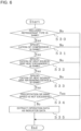
- Fig. 6 is a diagram for illustrating a flow of processing of extracting operation data according to Embodiment 1 of the present invention.
- the monitoring processing device 104 selects the second air-conditioning apparatus 101b having the same heat amount and the same processing effect associated with the heat amount as the first air-conditioning apparatus 101a, for example, the second air-conditioning apparatus 101b having the same model as the first air-conditioning apparatus 101a, and performs processing of extracting indicator data from operation data of the selected second air-conditioning apparatus 101b.
- the air-conditioning apparatus monitoring apparatus 109 determines whether or not such condition of equality, or equality condition, is satisfied for, for example, devices constituting the air-conditioning apparatus (refrigerant circuit) and other processing.
- the equality condition does not always require rigid equality and the equality condition may have a predefined range (range of equality) in which the equality condition can be determined as being satisfied.
- Step S30 the monitoring processing device 104 determines whether or not the type of refrigerant included in the refrigerant circuit is the same.
- the way of controlling devices constituting the refrigerant circuit also differs, leading to different pieces of operation data.
- the monitoring processing device 104 determines whether or not a specification of the compressor 1 is the same.
- the specification of the compressor 1 includes, for example, a compressor cylinder capacity and a compressor type (e.g., scroll compressor and rotary compressor).
- the specification of the compressor 1 is the same, the condition on the refrigerant flowrate (cooling capacity) can be considered as being equal.
- the monitoring processing device 104 determines whether or not the specification of the heat source-side heat exchanger 3 is the same.
- the specification of the heat source-side heat exchanger 3 includes, for example, the shape of fin, the pipe outer heat transfer area, and the pipe inner heat transfer area.
- the monitoring processing device 104 determines whether or not the specification of the heat source-side air-sending device 4 is the same.
- the specification of the heat source-side air-sending device 4 includes, for example, the shape of fin (e.g., propeller fan) and the range of number of revolutions.
- the condition on the heat transfer area can be considered as being equal. Further, when the specification of the heat source-side air-sending device 4 is the same, the condition on the flowrate can be considered as being equal. Thus, it is possible to consider that the condition on the heat transfer performance in the heat source-side heat exchanger 3 is equality.
- the processable heat amount and the processing efficiency are almost the same even under different specifications of other devices (e.g., pressure reducing mechanism type and accumulator) and other different conditions.
- past operation data of the first air-conditioning apparatus 101a stored in the storage device 105 serves as indicator data.
- an air-conditioning apparatus having another model name is often released although only a part of the specification is changed from existing one.
- operation data of the second air-conditioning apparatus 101b having a different model name but satisfying conditions can be used to detect an abnormality of the first air-conditioning apparatus 101a.
- Step S34 the monitoring processing device 104 determines whether or not precipitation or wind speed is excessive (whether or not operation data does not satisfy weather conditions).
- Data on weather weather information
- excessive precipitation is set as, for example, a day on which a heavy rain warning or a heavy rain advisory is issued in the installation area of the second air-conditioning apparatus 101b (housing 107b).
- excessive wind speed is set as, for example, a day on which a storm warning or a storm advisory is issued in the installation area of the second air-conditioning apparatus 101b.
- weather information provided from external institutions and operation data are associated with each other and stored in the storage device 105. Further, for example, it may be determined whether or not precipitation or wind speed is excessive based on specific values (e.g., precipitation of 5 mm/h and wind speed of 15 m/s).
- Step S35 operation data of the second air-conditioning apparatus 101b that satisfies the above-mentioned condition is extracted as indicator data.
- operation data of the second air-conditioning apparatus 101b that is not determined as indicator data may be used as indicator data at the time of abnormality detection processing in another first air-conditioning apparatus 101a.
- Step S5 the monitoring processing device 104 extracts operation data (hereinafter referred to as "steady indicator data") in the steady state from the indicator data in order to extract indicator data that is similar to the monitoring data extracted in Step S2.
- steady indicator data operation data
- Fig. 7 is a table for showing a relationship between an abnormality detection mode and an abnormality detection method according to Embodiment 1 of the present invention.
- the monitoring processing device 104 further extracts data on a variable item and a feature value from the extracted steady indicator data in accordance with the abnormality detection mode selected in Step S3.
- the extracted steady indicator data contains all the pieces of operation data such as all the temperatures and pressures detected in the selected second air-conditioning apparatus 101b.
- data on the variable item and the feature value necessary for abnormality detection is extracted from the steady indicator data.
- the feature value is a parameter that changes due to occurrence of an abnormality.
- the variable item is a parameter that changes without occurrence of an abnormality.
- the feature value and the variable item differ depending on the abnormality detection mode.
- an abnormality detection mode for detecting refrigerant amount insufficiency in the refrigerant circuit is selected.
- the degree of condenser outlet subcooling difference between saturation temperature of pressure detected by pressure sensor 201 and temperature detected by temperature sensor 203 is smaller in a case where the refrigerant amount is insufficient compared with a case where the refrigerant amount is not insufficient.
- the degree of condenser outlet subcooling changes depending on the outside air temperature even when the refrigerant amount does not decrease.
- the feature value and the variable item in the case where the abnormality detection mode for detecting refrigerant amount insufficiency is selected are set as the degree of condenser outlet subcooling and the outside air temperature, respectively.
- the degree of condenser outlet subcooling in the monitoring data and the degree of condenser outlet subcooling in the steady indicator data are compared with each other, to thereby determine insufficiency of the refrigerant amount.
- the steady indicator data contains operation data of the second air-conditioning apparatus 101b.
- insufficiency of the refrigerant amount in the second air-conditioning apparatus 101b results in abnormality detection of the refrigerant amount insufficiency.
- the feature value and the variable item in the case where the abnormality detection mode for detecting contamination of the heat source-side heat exchanger 3 is selected are set as the temperature difference between the condensing temperature and the outside air temperature and the outside air temperature, respectively.
- the temperature difference between the condensing temperature and the outside air temperature in the monitoring data and the temperature difference between the condensing temperature and the outside air temperature in the steady indicator data are compared with each other, to thereby determine contamination of the heat source-side heat exchanger 3.
- the abnormality detection for contamination of the heat source-side heat exchanger 3 can be carried out also in the heating operation mode.
- the feature value is set as the temperature difference between the evaporating temperature and the outside air temperature.
- an abnormality detection mode for detecting locking of the bypass pressure reducing mechanism 20 is selected.
- the degree of superheat of the refrigerant in the second flow passage of the subcooling heat exchanger 11 changes and cannot be controlled to a fixed value. For example, when a valve opening degree is fixed in an opening state, the degree of superheat increases by 10 degrees Celsius or more. Further, when the valve opening degree is fixed in a closed state, the refrigerant does not pass through the second flow passage, and thus the degree of superheat is 0.
- the feature value in the case where the abnormality detection mode for detecting locking of the bypass pressure reducing mechanism 20 is selected is set as the degree of superheat of the refrigerant in the subcooling heat exchanger 11. Further, the variable item is set as the opening degree of the bypass pressure reducing mechanism 20. The degree of superheat in the monitoring data and the degree of superheat in the steady indicator data are compared with each other, to thereby determine locking of the bypass pressure reducing mechanism 20.
- the feature value in the case where the abnormality detection mode for detecting degradation of the compressor is selected is the discharge temperature of the compressor 1. Further, the variable item is the condensing temperature and the evaporating temperature. The discharge temperature in the monitoring data and the discharge temperature in the steady indicator data are compared with each other, to thereby determine compressor degradation.
- Step S7 the arithmetic unit 120 calculates an average value of pieces of feature value data for each variable item.
- the variable item is divided at a fixed interval or by other methods to divide the feature value data, and the average value of a group of pieces of feature value data is calculated.
- the outside air temperature is divided in units of 4.5 degrees Celsius (..., 20.5 degrees Celsius to 25.0 degrees Celsius, 25.5 degrees Celsius to 30.0 degrees Celsius, ...) to calculate the average value.
- Fig. 8 is a graph for showing an example of a relationship between the steady indicator data and the monitoring data, which are on the feature value and the variable item, according to Embodiment 1 of the present invention.
- the arithmetic unit 120 calculates a difference value between the average value of feature values and the monitoring data.
- the control unit 121 determines whether or not the difference value calculated by the arithmetic unit 120 is equal to or larger than a predetermined value.
- the control unit 121 determines that the difference value is equal to or larger than the predetermined value, the control unit 121 determines that the value is abnormal and issues an abnormality notification (Step S10).
- the control unit 121 determines that the difference is not equal to or larger than the predetermined value, the control unit 121 determines that the value is normal and issues a normality notification (Step S11).
- the determination of an abnormality in a case where there are a plurality of pieces of monitoring data is not particularly limited. For example, when the control unit 121 determines that the difference is equal to or larger than a predetermined value for at least one of the plurality of pieces of monitoring data, the control unit 121 may determine that there is an abnormality. Instead, when the control unit 121 determines that the difference is equal to or larger than a predetermined value for every one of the plurality of pieces of monitoring data, the control unit 121 may determine that there is an abnormality.
- Step S12 the monitoring processing device 104 determines whether or not the processing is complete for all the abnormality detection modes. When the monitoring processing device 104 determines that the processing is not complete, the monitoring processing device 104 returns to Step S2, selects an abnormality detection mode that has not been selected yet, and performs determination of abnormality detection.
- Step S13 the control unit 121 determines whether or not the difference value between the average value of feature values and the monitoring data is equal to or smaller than an appropriate difference value for all of the abnormality detection modes.
- the control unit 121 determines that the difference is equal to or smaller than the appropriate difference value
- the control unit 121 causes the storage device 105 to store operation data of the first air-conditioning apparatus 101a.
- the storage device 105 stores operation data of the first air-conditioning apparatus 101a.
- the control unit 121 through storage of operation data containing monitoring data that is determined as being equal to or smaller than an appropriate difference value, it is possible to store operation data for which an abnormality has not occurred. Therefore, it is possible to ensure that the indicator data is an aggregate of pieces of normal operation data and to ensure reliability of data.
- reliability of operation data to be stored into the storage device 105 can be improved by causing the difference value threshold value of Step S13 to be smaller than the difference value determination value of Step S9.
- Operation data is stored in the storage device 105 after processing of Step S13 for one year after installation of the air-conditioning apparatus, for example.
- operation data for one year can be stored
- a series of pieces of operation data on outside air temperature and indoor loads can be stored.
- continuous storage of data for three or four years may result in a failure to determine degradation when degradation over time has progressed.
- the system of Embodiment 1 stores operation data for only a predetermined period of time after installation of the air-conditioning apparatus.
- the monitoring processing device 104 of Embodiment 1 collects operation data of the second air-conditioning apparatus 101b and stores the operation data into the storage device 105, to thereby be able to detect an abnormality based on a larger amount of operation data.
- Fig. 9 is a table for showing an example of a relationship between classification items and storage locations of operation data according to Embodiment 2 of the present invention.
- the storage location of operation data may be classified and divided based on conditions on abnormality detection for the air-conditioning apparatus 101, such as a refrigerant name and the specification of the compressor, and then the operation data may be stored in the storage device 105 based thereon.
- the air-conditioning apparatus monitoring system 100 includes two storage devices 105. Further, each storage device 105 includes two storage devices 150.
- the storage area of operation data in the entire system can be divided into four areas.
- the monitoring processing device 104 classifies the storage location of operation data depending on whether the refrigerant type is R32 or R410A and on whether the compressor 1 is a rotary compressor or a scroll compressor. For example, operation data of the air-conditioning apparatus 101 in which the refrigerant type is R32 and the compressor 1 is a rotary compressor is classified such that the operation data is stored in the storage device 150a of the storage device 105a. Further, operation data of the air-conditioning apparatus 101 in which the refrigerant type is R32 and the compressor 1 is a scroll compressor is classified such that the operation data is stored in the storage device 150b of the storage device 105a.
- operation data of the air-conditioning apparatus 101 in which the refrigerant type is R410A and the compressor 1 is a rotary compressor is classified such that the operation data is stored in the storage device 150a of the storage device 105b.
- operation data of the air-conditioning apparatus 101 in which the refrigerant type is R410A and the compressor 1 is a scroll compressor is classified such that the operation data is stored in the storage device 150b of the storage device 105b.
- the air-conditioning apparatus monitoring system 100 of Embodiment 2 classifies the storage location of operation data based on conditions on abnormality detection for the air-conditioning apparatus 101 and stores the operation data based on the classification.
- operation data can be accessed by specifying in advance the storage device 105 or other similar apparatuses at the time of, for example, extraction of operation data by the monitoring processing device 104. Therefore, it is possible to speed up information processing by avoiding unnecessary data access. For example, unnecessary data access can be avoided more effectively by, for example, classifying the storage location of operation data based on conditions on abnormality detection in a frequently selected abnormality detection mode.
- Fig. 10 is a table for showing an example of a relationship between related items and air-conditioning apparatuses according to Embodiment 3 of the present invention.
- an installation crew member construction crew member
- the local controller 102 inputs an extended pipe length (longest part) and an extended pipe height difference in the air-conditioning apparatus 101 into the local controller 102 as data at the time of installation of the air-conditioning apparatus 101.
- the local controller 102 transmits the data to the monitoring processing device 104.
- the monitoring processing device 104 stores the data into the storage device 105.
- classification is made based on the extended pipe length and the extended pipe height difference, and the storage location of operation data of each air-conditioning apparatus 101 is defined.
- it is possible to access operation data by specifying in advance the storage device 105 or other similar apparatuses at the time of, for example, extraction of operation data by the monitoring processing device 104. Therefore, it is possible to speed up information processing by avoiding unnecessary data access.
- operation data stored in the storage device 105 is classified based on the extended pipe length (longest part) or the extended pipe height difference.
- the control unit 121 extracts operation data of the second air-conditioning apparatus 101b, which is classified into the same category as the first air-conditioning apparatus 101a, at the time of performing abnormality detection for contamination of the heat source-side heat exchanger 3, and determines abnormality detection.
- the number of connected use units 303 and the capacity of the use-side heat exchanger 15 of each use unit 303 in the air-conditioning apparatus 101 may be used to classify operation data for storage into the storage device 105.
- the number of use-side pressure reducing mechanisms 14 when the number of use units 303 increases, the number of use-side pressure reducing mechanisms 14 also increases.
- the total amount of valve opening degrees in the use units 303 increases.
- the refrigerant may be less likely to flow into the bypass pressure reducing mechanism 20, and detection of an abnormality may be affected.
- operation data stored in the storage device 105 is classified based on the number of connected use units 303 and the capacity of the use-side heat exchanger 15 of each use unit 303. Then, the control unit 121 extracts operation data of the second air-conditioning apparatus 101b, which is classified into the same category as the first air-conditioning apparatus 101a, at the time of performing abnormality detection for locking of the bypass pressure reducing mechanism 20, and determines abnormality detection.
Landscapes
- Engineering & Computer Science (AREA)
- Chemical & Material Sciences (AREA)
- Combustion & Propulsion (AREA)
- Mechanical Engineering (AREA)
- General Engineering & Computer Science (AREA)
- Signal Processing (AREA)
- Physics & Mathematics (AREA)
- Fuzzy Systems (AREA)
- Mathematical Physics (AREA)
- Air Conditioning Control Device (AREA)
Description
- The present invention relates to an air-conditioning apparatus monitoring apparatus and a method of monitoring air-conditioning apparatus for monitoring operation states of air-conditioning apparatuses. In particular, the present invention relates to an apparatus for detecting abnormalities of air-conditioning apparatuses.
- Hitherto, there have been proposed numerous systems configured to detect an abnormality of an air-conditioning apparatus, and research and development are ongoing to enable detection of an abnormality before the air-conditioning apparatus cannot be operated. One such abnormality detection system is configured to detect an abnormality through use of data (operation data) on past operation states of air-conditioning apparatuses (e.g., refer to Patent Literature 1).
-
- Patent Literature 1:
Japanese Unexamined Patent Application Publication No. 2006-275411 Fig. 1 ) - Patent Literature 2:
WO2014/064792 - For example, the abnormality detection system disclosed in
Patent Literature 1 uses past operation state data to detect an abnormality of an air-conditioning apparatus. The abnormality detection system compares operation data of an air-conditioning apparatus with past operation data of another air-conditioning apparatus, here refereed to as a second air-conditioning apparatus, which is similar to the operation data of the air-conditioning apparatus in terms of operation condition, to thereby detect an abnormality of the air-conditioning apparatus. - However, in the abnormality detection system disclosed in
Patent Literature 1, the two air-conditioning apparatuses are compared with each other on the assumption that the air-conditioning apparatus and the second air-conditioning apparatus have the same configuration, are installed close to each other and environmental conditions are similar to each other. Thus, operation data of an air-conditioning apparatus that deviates from the assumption cannot be referred to, which means that there is limited operation data for reference. Accordingly, there are few opportunities to acquire similar past operation data, resulting in a limited improvement in accuracy of detecting an abnormality. - The present invention has been made to overcome the above-mentioned problem, and an object thereof is to provide an-conditioning apparatus monitoring apparatus and the like, which are capable of detecting an abnormality based on a larger amount of operation data.
- According to the present invention, there is provided a monitoring apparatus for monitoring air-conditioning apparatuses according to
claim 1, a method of monitoring air-conditioning apparatuses according to the invention is disclosed inclaim 10. The sub-claims defining further embodiments of the invention. - According to the present invention, the operation data of the plurality of air-conditioning apparatuses is collected and stored for a fixed period of time, and a larger amount of operation data to be compared with operation data of the air-conditioning apparatus that is the target of monitoring (target of abnormality detection) can be acquired. Therefore, it is possible to provide the monitoring apparatus for monitoring air-conditioning apparatuses, which is capable of performing the abnormality detection more quickly and accurately than the related art.
-
- [
Fig. 1] Fig. 1 is a diagram for illustrating a system configuration of an air-conditioningapparatus monitoring system 100 according toEmbodiment 1 of the present invention. - [
Fig. 2] Fig. 2 is a block diagram for illustrating a configuration of amonitoring processing device 104 according toEmbodiment 1 of the present invention. - [
Fig. 3] Fig. 3 is a block diagram for illustrating a configuration of astorage device 105 according toEmbodiment 1 of the present invention. - [
Fig. 4] Fig. 4 is a diagram for illustrating a device configuration and other configurations of an air-conditioning apparatus 101 according toEmbodiment 1 of the present invention. - [
Fig. 5] Fig. 5 is a diagram for illustrating a flow of processing of abnormality detection and other processing according toEmbodiment 1 of the present invention. - [
Fig. 6] Fig. 6 is a diagram for illustrating a flow of processing of extracting operation data according toEmbodiment 1 of the present invention. - [
Fig. 7] Fig. 7 is a table for showing a relationship between an abnormality detection mode and an abnormality detection method according toEmbodiment 1 of the present invention. - [
Fig. 8] Fig. 8 is a graph for showing an example of a relationship between steady indicator data and monitoring data, which are on a feature value and a variable item, according toEmbodiment 1 of the present invention. - [
Fig. 9] Fig. 9 is a table for showing an example of a relationship between classification items and storage locations of operation data according toEmbodiment 2 of the present invention. - [
Fig. 10] Fig. 10 is a table for showing an example of a relationship between related items and air-conditioning apparatuses according toEmbodiment 3 of the present invention. - Now, an air-conditioning apparatus monitoring system according to embodiments of the present invention is described with reference to the drawings. In the drawings, components denoted by the same reference symbols correspond to the same or equivalent components. This is common throughout the embodiments described below. Further, the forms of the components described herein are merely examples, and the components are not limited to the forms described herein. In particular, the combinations of the components are not limited to only the combinations in each embodiment, and the components described in another embodiment may be applied to still another embodiment. Further, unless otherwise necessary to be distinguished or specified, a plurality of devices of the same type or other components, which are distinguished from one another by suffixes or in another way, may be described without the suffixes. Further, in the drawings, the size relationship between the components may be different from the actual size relationship. In addition, a high-and-low relationship or other relationships of temperature, pressure, or other factors are not determined in relation to particular absolute values, but are determined in a relative manner based on a state, an operation, or other factors of systems, devices, or other conditions.
-
Fig. 1 is a diagram for illustrating a system configuration of an air-conditioningapparatus monitoring system 100 according toEmbodiment 1 of the present invention, which is constructed mainly by an air-conditioningapparatus monitoring apparatus 109. Now, a description is given of the configuration of the air-conditioningapparatus monitoring system 100 ofEmbodiment 1 with reference toFig. 1 . The air-conditioningapparatus monitoring system 100 ofEmbodiment 1 includes the air-conditioningapparatus monitoring apparatus 109 configured to monitor an air-conditioning apparatus 101 and perform abnormality detection and other processing. The air-conditioningapparatus monitoring system 100 ofEmbodiment 1 includes a first air-conditioning apparatus 101a and a second air-conditioning apparatus 101b as the air-conditioning apparatus 101. In addition, the air-conditioningapparatus monitoring system 100 includes alocal controller 102, which corresponds to each air-conditioning apparatus 101 and is configured to perform control of the air-conditioning apparatus 101 and other processing. - A first
local controller 102a is configured to perform control of the first air-conditioning apparatus 101a and other processing, and a secondlocal controller 102b is configured to perform control of the second air-conditioning apparatus 101b and other processing. Further, the air-conditioning apparatus 101 and thelocal controller 102 are installed in a housing 107 such as a building, an apartment building, or a commercial facility. The first air-conditioning apparatus 101a and the firstlocal controller 102a are installed in ahousing 107a, and the second air-conditioning apparatus 101b and the secondlocal controller 102b are installed in ahousing 107b. - In
Embodiment 1, the first air-conditioning apparatus 101a is set as an air-conditioning apparatus to be monitored (to be subjected to abnormality detection). Further, the second air-conditioning apparatus 101b is set as an air-conditioning apparatus whose operation data is to be collected by amonitoring processing device 104. Thus, although only one second air-conditioning apparatus 101b is illustrated inFig. 1 , the plurality of second air-conditioning apparatuses 101b are connected to anelectrical communication line 103 via thelocal controllers 102 in actuality. The lower the number of second air-conditioning apparatuses 101b is, the larger the amount of available operation data is expected. The first air-conditioning apparatus 101a may be the second air-conditioning apparatus 101b, namely, an air-conditioning apparatus for collection of operation data. Further, the second air-conditioning apparatus 101b may be the first air-conditioning apparatus 101a, namely, an air-conditioning apparatus to be monitored. - Further, the air-conditioning
apparatus monitoring system 100 includes the air-conditioningapparatus monitoring apparatus 109 including themonitoring processing device 104 and astorage device 105 in aremote management center 106. Themonitoring processing device 104 is connected to eachlocal controller 102 described above via theelectrical communication line 103 for communication, and can transmit/receive signals containing various kinds of data. Themonitoring processing device 104 ofEmbodiment 1 is configured to perform processing such as abnormality detection and storage of data into thestorage device 105 for data contained in signals transmitted from eachlocal controller 102. Thestorage device 105 is connected to themonitoring processing device 104 for communication. Thestorage device 105 is configured to store data contained in signals transmitted from themonitoring processing device 104. Further, thestorage device 105 transmits, to themonitoring processing device 104, signals containing operation data necessary for themonitoring processing device 104 to perform processing. InEmbodiment 1, it is assumed that the air-conditioningapparatus monitoring apparatus 109 includes twostorage devices 105, namely, astorage device 105a and astorage device 105b. - The
local controller 102 is connected to the corresponding air-conditioning apparatus 101 for communication directly or via a dedicated adaptor, and can communicate to/from the air-conditioning apparatus 101. Further, thelocal controller 102 is also connected to themonitoring processing device 104 via theelectrical communication line 103, and can communicate to/from themonitoring processing device 104. Thelocal controller 102 controls the air-conditioning apparatus 101 by giving an instruction to the air-conditioning apparatus 101 based on operation data, which is data on an operation of the air-conditioning apparatus 101 transmitted regularly from the air-conditioning apparatus 101. Further, thelocal controller 102 stores operation data, which is obtained from the air-conditioning apparatus 101, for a predetermined period of time (e.g., one day), and transmits the operation data to themonitoring processing device 104 regularly. -
Fig. 2 is a block diagram for illustrating a configuration of themonitoring processing device 104 according toEmbodiment 1 of the present invention. Themonitoring processing device 104 ofEmbodiment 1 includes anarithmetic unit 120, acontrol unit 121, acommunication unit 122, adisplay unit 123, and astorage unit 124. Thearithmetic unit 120 is configured to perform arithmetic operations necessary for thecontrol unit 121 to perform processing, for example, calculation of an average value of pieces of indicator data. Thecontrol unit 121 is configured to coordinate operations to be executed by themonitoring processing device 104, such as an instruction of operation-related data to thelocal controller 102, selection of an abnormality detection mode, and abnormality detection. - The
communication unit 122 is configured to acquire signals containing operation data transmitted from thelocal controller 102 via theelectrical communication line 103. Further, thecommunication unit 122 receives past operation data stored in thestorage device 105, and transmits operation data acquired from thelocal controller 102 to thestorage device 105. InEmbodiment 1, as described later, it is assumed that thecommunication unit 122 transmits, to thestorage device 105, operation data that is determined by thecontrol unit 121 as data to be stored into thestorage device 105. Thedisplay unit 123 is configured to display, for example, a result of processing performed by thecontrol unit 121. InEmbodiment 1, thedisplay unit 123 displays a determination result in the abnormality detection processing. Thestorage unit 124 is configured to store data necessary for themonitoring processing device 104 to perform processing, for example, operation data transmitted from thelocal controller 102. - Units of the
monitoring processing device 104 ofEmbodiment 1, such as thearithmetic unit 120 and thecontrol unit 121, can be implemented as apparatuses by respectively different pieces of hardware. In this description, while respective units of themonitoring processing device 104 are implemented by arithmetic control means (computer), for example, a central processing unit (CPU), those processing procedures may be programed in advance and implemented by, for example, software and firmware. The arithmetic control means executes those programs to perform processing based on those programs, to thereby implement processing performed by the respective units described above. Data of those programs may be stored in, for example, thestorage unit 124. -
Fig. 3 is a block diagram for illustrating a configuration of thestorage device 105 according toEmbodiment 1 of the present invention. Thestorage device 105 ofEmbodiment 1 includes two storage devices 150 (150a and 150b). Further, respective storage devices 150 include communication units 140 (140a and 140b) and storage units 141 (141a and 141b). The communication unit 140 is configured to communicate signals containing operation data to/from themonitoring processing devices 104. Further, the storage unit 141 is configured to store operation data transmitted from themonitoring processing device 104. For example, data (e.g., data on used refrigerant and component devices) on the second air-conditioning apparatus 101b and operation data of the second air-conditioning apparatus 101b are stored in association with each other. Further, thestorage device 105 transmits, to themonitoring processing device 104, operation data necessary for themonitoring processing device 104 to perform processing. Thestorage device 105 desirably has a storage capacity of operation data for approximately one year of the first air-conditioning apparatus 101a and the second air-conditioning apparatus 101b though the storage capacity is not particularly limited thereto. For example, when operation data can be stored for one year after installation of the air-conditioning apparatus, it is possible to store a series of pieces of operation data on outside air temperature and indoor loads for respective seasons. Further, for example, operation data for three or more years may be stored in vain because operation data that contains a variation due to degradation over time may be used for abnormality detection, resulting in a failure to detect an abnormality due to degradation over time. -
Fig. 4 is a diagram for illustrating a device configuration and other configurations of the air-conditioning apparatus 101 according toEmbodiment 1 of the present invention. As described above, the air-conditioning apparatus 101 is installed in the housing 107. The air-conditioning apparatus 101 ofEmbodiment 1 is an apparatus capable of employing vapor-compression refrigeration to perform refrigerant cycle operations for circulating refrigerant for air conditioning, to thereby cause each use unit 303 to process the selected cooling instruction (cooling on/off) or heating instruction (heating on/off) and cool or heat an air-conditioning target space. The air-conditioning apparatus 101 ofEmbodiment 1 is configured such that aheat source unit 301 and the use units 303 (303a and 303b) are connected to each other via anindoor liquid pipe 27 and anindoor gas pipe 28, which serve as refrigerant pipes. - The
heat source unit 301 ofEmbodiment 1 includes acompressor 1, a four-way valve 2, a heat source-side heat exchanger 3, a heat source-side air-sendingdevice 4, asubcooling heat exchanger 11, anaccumulator 19, a bypasspressure reducing mechanism 20, and abypass pipe 21. Thecompressor 1 is configured to suck and compress refrigerant such that the compressed refrigerant has high temperature and high pressure, and discharge the refrigerant. Thecompressor 1 ofEmbodiment 1 includes, for example, an inverter apparatus, and can finely change the capacity (amount of refrigerant to be sent out per unit time) of thecompressor 1 by enabling the number of revolutions (driving frequency) to be controlled. In this case, thecompressor 1 is one of devices for controlling refrigerant pressure. The four-way valve 2 is a valve configured to switch the direction in which the refrigerant flows. The four-way valve 2 has four ports, namely, first to fourth ports. The first port, the second port, the third port, and the fourth port are connected to a discharge side of thecompressor 1, the heat source-side heat exchanger 3, a suction side of thecompressor 1, and theindoor gas pipe 28, respectively. The four-way valve 2 changes the flow passage by switching between a state (state indicated by solid line ofFig. 1 ) in which the first port and the second port communicate to each other and the third port and the fourth port communicate to each other and a state (state indicated by broken line ofFig. 1 ) in which the first port and the fourth port communicate to each other and the second port and the third port communicate to each other. - The heat source-
side heat exchanger 3 is, for example, a cross-fin type fin-and-tube heat exchanger including a heat transfer tube and many fins. The heat source-side heat exchanger 3 is configured to, for example, exchange heat between outside air and refrigerant. The heat source-side heat exchanger 3 serves as an evaporator configured to evaporate and vaporize refrigerant at the time of, for example, a heating operation. Further, the heat source-side heat exchanger 3 serves as a condenser configured to condense and liquify refrigerant in a cooling operation. Further, the heat source-side air-sendingdevice 4 is a propeller fan or other devices to be driven by a motor (not shown) including, for example, a DC fan motor. The heat source-side air-sendingdevice 4 is configured to supply, for example, outside air to the heat source-side heat exchanger 3. The heat source-side air-sendingdevice 4 ofEmbodiment 1 comprises a fan capable of changing the flowrate of air to be supplied to the heat source-side heat exchanger 3. In this case, the heat source-side air-sending device is one of devices for controlling refrigerant pressure. Theaccumulator 19 is configured to store excessive refrigerant in the refrigerant circuit during the operation. Further, theaccumulator 19 accumulates liquid refrigerant that temporarily occurs at the time of change in operation state, to thereby prevent a large amount of liquid refrigerant from flowing into thecompressor 1. - The
subcooling heat exchanger 11 comprises, for example, a double pipe heat exchanger. Thesubcooling heat exchanger 11 includes a first flow passage and a second flow passage, and is an intermediate heat exchanger configured to exchange heat between flows of refrigerant passing through respective flow passages. Refrigerant flowing into or out of the heat source-side heat exchanger 3 passes through the first flow passage, while a refrigerant that has passed through the bypasspressure reducing mechanism 20 flows into the second flow passage and then out to thebypass pipe 21. Thesubcooling heat exchanger 11 is not limited to the double pipe heat exchanger, and may have any structure as long as thesubcooling heat exchanger 11 allows exchange of heat between the refrigerant passing through the first flow passage and the refrigerant passing through the second flow passage. The bypasspressure reducing mechanism 20 is configured to adjust the pressure and flowrate of refrigerant passing through thesubcooling heat exchanger 11 and thebypass pipe 21. - In the
heat source unit 301, apressure sensor 201 is provided to a discharge side pipe of thecompressor 1 and apressure sensor 211 is provided to a suction-side pipe of thecompressor 1. Thepressure sensor 201 and thepressure sensor 211 are configured to measure (detect) pressures of refrigerant at respective installation positions. Further, atemperature sensor 202 is provided to the discharge side of thecompressor 1, and atemperature sensor 203 is provided to a liquid side (liquid refrigerant side or two-phase gas-liquid refrigerant passage side) of the heat source-side heat exchanger 3. Further, atemperature sensor 207 is installed between a high-pressure side of thesubcooling heat exchanger 11 and an indoor liquid pipe, atemperature sensor 212 is installed between the bypasspressure reducing mechanism 20 and a low-pressure side of thesubcooling heat exchanger 11, and atemperature sensor 213 is installed at a low-pressure side outlet of thesubcooling heat exchanger 11. Each temperature sensor is configured to measure refrigerant temperature at the installation position. Further, an outsideair temperature sensor 204 is installed at, for example, an air inlet of theheat source unit 301, and is configured to measure outside air temperature. - Further, the air-
conditioning apparatus 101 includes acontroller 108 configured to control the operation state of the air-conditioning apparatus 101. InEmbodiment 1, thecontroller 108 transmits operation data, which is obtained by, for example, measurement by various types of sensors installed in the air-conditioning apparatus 101, to thelocal controller 102. - The use unit 303 includes a use-side
pressure reducing mechanism 14 and a use-side heat exchanger 15. The use-sidepressure reducing mechanism 14 is configured to adjust the amount and pressure of refrigerant passing through the use-side heat exchanger 15. The use-side heat exchanger 15 is configured to exchange heat between air and refrigerant in, for example, the air-conditioning target space. For example, the use-side heat exchanger 15 serves as a condenser in a heating operation, and condenses and liquifies refrigerant. Further, the use-side heat exchanger 15 serves as an evaporator in a cooling operation, and evaporates and vaporizes refrigerant. - Further, in the use unit 303, a temperature sensor 208 is provided to a liquid side (liquid refrigerant side or two-phase gas-liquid refrigerant passage side) of the use-side heat exchanger 15. Further, the temperature sensor 209 is provided to a gas side (gas refrigerant side or two-phase gas-liquid refrigerant passage side) of the use-side heat exchanger 15. Further, a temperature sensor 210 is configured to measure temperature of indoor air (air of air-conditioning target space).
- In the air-
conditioning apparatus 101, thecontroller 108 controls devices included in theheat source unit 301 and the use unit 303 in accordance with an instruction for air-conditioning required by the use unit 303 and operates in a cooling operation mode or a heating operation mode, to thereby achieve air conditioning for the air-conditioning target space. - First, the cooling operation mode is described. In the cooling operation mode, the
controller 108 switches the four-way valve 2 such that the first port and the second port communicate to each other and the third port and the fourth port communicate to each other at the same time. - The high-temperature, high-pressure gas refrigerant discharged from the
compressor 1 flows into the heat source-side heat exchanger 3 via the four-way valve 2. The refrigerant, which has flowed into the heat source-side heat exchanger 3, rejects heat into the outside air through air sent by the heat source-side air-sendingdevice 4. After that, thesubcooling heat exchanger 11 cools the refrigerant by a low-pressure refrigerant, and then, the refrigerant is divided into refrigerant flowing through theindoor liquid pipe 27 and refrigerant flowing through the bypasspressure reducing mechanism 20. The pressure of the refrigerant flowing through theindoor liquid pipe 27 is reduced by the use-sidepressure reducing mechanism 14, and the refrigerant turns into low-pressure two-phase refrigerant. Then, the low-pressure two-phase refrigerant cools indoor air while passing through the use-side heat exchanger 15, and turns into low-pressure gas refrigerant. After that, the low-pressure gas refrigerant flows through theindoor gas pipe 28 and the four-way valve 2 into theaccumulator 19, and then is sucked into thecompressor 1 again. - The
controller 108 controls thecompressor 1 such that evaporating temperature in the use-side heat exchanger 15 is a predetermined value. The evaporating temperature is saturation temperature under the pressure detected by thepressure sensor 211. Further, thecontroller 108 controls the heat source-side air-sendingdevice 4 such that condensing temperature in the heat source-side heat exchanger 3 is a predetermined value. The condensing temperature is saturation temperature under the pressure detected by thepressure sensor 201. Further, thecontroller 108 controls the bypasspressure reducing mechanism 20 such that a degree of bypass superheat is a predetermined value. The degree of bypass superheat is a temperature difference obtained by subtracting the temperature detected by thetemperature sensor 212 from the temperature detected by thetemperature sensor 213. Further, thecontroller 108 controls the use-sidepressure reducing mechanism 14a such that a degree of indoor superheat is a predetermined value. The degree of indoor superheat is a temperature difference obtained by subtracting the temperature detected by the temperature sensor 208 from the temperature detected by the temperature sensor 209. - On the other hand, in the heating operation mode, the
controller 108 switches the four-way valve 2 such that the first port and the second port communicate to each other and the third port and the fourth port communicate to each other at the same time. Further, the bypasspressure reducing mechanism 20 has a fully closed opening degree. - The high-temperature and high-pressure gas refrigerant discharged from the
compressor 1 flows through the four-way valve 2 into theindoor gas pipe 28, heats indoor air in the use-side heat exchanger 15, and turns into a high-pressure liquid refrigerant. After that, the pressure of the high-pressure liquid refrigerant is reduced by the use-sidepressure reducing mechanism 14, and the refrigerant turns into low-pressure two-phase refrigerant. Then, the low-pressure two-phase refrigerant passes through thesubcooling heat exchanger 11 via theindoor liquid pipe 27, and flows into the heat source-side heat exchanger 3. The refrigerant, which has flowed into the heat source-side heat exchanger 3, receives heat from outside air, and turns into low-pressure gas refrigerant. Then, the low-pressure gas refrigerant passes through theaccumulator 19 via the four-way valve 2, and is sucked into thecompressor 1 again. - The
controller 108 controls thecompressor 1 such that condensing temperature in the use-side heat exchanger 15 is a predetermined value. Further, thecontroller 108 controls the heat source-side air-sendingdevice 4 such that evaporating temperature in the heat source-side heat exchanger 3 is a predetermined value. Further, thecontroller 108 controls the use-sidepressure reducing mechanism 14a such that a degree of indoor subcooling is a predetermined value. The degree of indoor subcooling is a temperature difference obtained by subtracting the temperature detected by the temperature sensor 208 from the saturation temperature under the pressure detected by thepressure sensor 201. -
Fig. 5 is a diagram for illustrating a flow of processing of abnormality detection and other processing according toEmbodiment 1 of the present invention. Now, a description is given of processing to be performed by the air-conditioning apparatus monitoring apparatus 109 (monitoring processing device 104) ofEmbodiment 1 with reference toFig. 5 . The description is based on the assumption that themonitoring processing device 104 uses operation data of the first air-conditioning apparatus 101a in the cooling operation mode to perform abnormality determination processing. - In Step S1, when one day has passed (for example, when twelve o'clock at night is reached), each
local controller 102 transmits a signal. Thecommunication unit 122 of themonitoring processing device 104 obtains operation data of each air-conditioning apparatus 101 from the transmitted signal. The operation data is stored into thestorage unit 124. In this description, it is assumed that the operation data is collected on a day-to-day basis, but the frequency is not limited thereto. - Then, in Step S2, the
monitoring processing device 104 extracts data on operations in a steady state from among transmitted operation data as monitoring data. Determination of monitoring data is performed as follows. First, steady state parameters for determining whether or not the air-conditioning apparatus 101 is in the steady state are defined in advance. InEmbodiment 1, for example, the steady state parameters are the driving frequency of thecompressor 1, the pressure (high pressure) detected by thepressure sensor 201, the pressure (low pressure) detected by thepressure sensor 211, the degree of heat source-side outlet subcooling (saturation temperature converted from pressure detected by pressure sensor 201 - temperature detected by temperature sensor 203) and the degree of bypass superheat (temperature detected by temperature sensor 213 - temperature detected by temperature sensor 212). Thearithmetic unit 120 calculates a moving average value of detection values (instantaneous values) for 15 minutes in relation to each steady state parameter. After that, when a difference between the moving average value and each instantaneous value at each measurement time is equal to or smaller than a predetermined value, for example, thearithmetic unit 120 determines that the steady state parameter at that measurement time is stable. Then, thearithmetic unit 120 sets, as the steady state, a state in which all the steady state parameters are determined as being stable. In this description, a predetermined value is used, but an aberration or other values may be used to perform determination. The calculation and determination as described above are executed at each measurement time, and operation data in a measurement time determined as being the steady state is extracted as monitoring data for that day. - In Step S3, the
monitoring processing device 104 selects an abnormality detection mode for determining an abnormality. The abnormality detection mode inEmbodiment 1 is refrigerant amount insufficiency detection, heat exchanger contamination detection for a heat source-side heat exchanger, lock detection for the bypasspressure reducing mechanism 20, or compressor degradation detection. -
Fig. 6 is a diagram for illustrating a flow of processing of extracting operation data according toEmbodiment 1 of the present invention. In Step S4, themonitoring processing device 104 selects the second air-conditioning apparatus 101b having the same heat amount and the same processing effect associated with the heat amount as the first air-conditioning apparatus 101a, for example, the second air-conditioning apparatus 101b having the same model as the first air-conditioning apparatus 101a, and performs processing of extracting indicator data from operation data of the selected second air-conditioning apparatus 101b. In the selection of the second air-conditioning apparatus 101b, the air-conditioningapparatus monitoring apparatus 109 determines whether or not such condition of equality, or equality condition, is satisfied for, for example, devices constituting the air-conditioning apparatus (refrigerant circuit) and other processing. However, depending on specifics of a condition, the equality condition does not always require rigid equality and the equality condition may have a predefined range (range of equality) in which the equality condition can be determined as being satisfied. - First, in Step S30, the
monitoring processing device 104 determines whether or not the type of refrigerant included in the refrigerant circuit is the same. When the type of refrigerant differs, the way of controlling devices constituting the refrigerant circuit also differs, leading to different pieces of operation data. When it is determined that the type of refrigerant is the same, in Step S31, themonitoring processing device 104 determines whether or not a specification of thecompressor 1 is the same. The specification of thecompressor 1 includes, for example, a compressor cylinder capacity and a compressor type (e.g., scroll compressor and rotary compressor). When the specification of thecompressor 1 is the same, the condition on the refrigerant flowrate (cooling capacity) can be considered as being equal. - Further, in Step S32, the
monitoring processing device 104 determines whether or not the specification of the heat source-side heat exchanger 3 is the same. The specification of the heat source-side heat exchanger 3 includes, for example, the shape of fin, the pipe outer heat transfer area, and the pipe inner heat transfer area. When themonitoring processing device 104 determines that the specification of the heat source-side heat exchanger 3 is the same, in Step S33, themonitoring processing device 104 further determines whether or not the specification of the heat source-side air-sendingdevice 4 is the same. The specification of the heat source-side air-sendingdevice 4 includes, for example, the shape of fin (e.g., propeller fan) and the range of number of revolutions. When the specification of the heat source-side heat exchanger 3 is the same, the condition on the heat transfer area can be considered as being equal. Further, when the specification of the heat source-side air-sendingdevice 4 is the same, the condition on the flowrate can be considered as being equal. Thus, it is possible to consider that the condition on the heat transfer performance in the heat source-side heat exchanger 3 is equality. - For example, regarding the second air-
conditioning apparatus 101b, when the used refrigerant is the same, and the specifications of thecompressor 1, the heat source-side heat exchanger 3, and the heat source-side air-sendingdevice 4 can be considered as being equal, the processable heat amount and the processing efficiency are almost the same even under different specifications of other devices (e.g., pressure reducing mechanism type and accumulator) and other different conditions. As a result, past operation data of the first air-conditioning apparatus 101a stored in thestorage device 105 serves as indicator data. Further, for example, in the development of an air-conditioning apparatus, an air-conditioning apparatus having another model name is often released although only a part of the specification is changed from existing one. Under such circumstances, operation data of the second air-conditioning apparatus 101b having a different model name but satisfying conditions can be used to detect an abnormality of the first air-conditioning apparatus 101a. Thus, it is possible to drastically increase the amount of operation data that can be referred to in the abnormality detection processing. As a result, more opportunities for detection can be obtained and the detection accuracy improves. - Further, in
Embodiment 1, in Step S34, themonitoring processing device 104 determines whether or not precipitation or wind speed is excessive (whether or not operation data does not satisfy weather conditions). Data on weather (weather information) is used to avoid extraction of operation data, which is obtained when the air-conditioning apparatus is operated under extreme weather conditions, for example, a typhoon, as indicator data, to thereby prevent erroneous detection in the abnormality detection. In this case, excessive precipitation is set as, for example, a day on which a heavy rain warning or a heavy rain advisory is issued in the installation area of the second air-conditioning apparatus 101b (housing 107b). Further, excessive wind speed is set as, for example, a day on which a storm warning or a storm advisory is issued in the installation area of the second air-conditioning apparatus 101b. To implement the determination in Step S34, for example, weather information provided from external institutions and operation data are associated with each other and stored in thestorage device 105. Further, for example, it may be determined whether or not precipitation or wind speed is excessive based on specific values (e.g., precipitation of 5 mm/h and wind speed of 15 m/s). - Then, in Step S35, operation data of the second air-
conditioning apparatus 101b that satisfies the above-mentioned condition is extracted as indicator data. In this case, for example, operation data of the second air-conditioning apparatus 101b that is not determined as indicator data may be used as indicator data at the time of abnormality detection processing in another first air-conditioning apparatus 101a. - Then, in Step S5, the
monitoring processing device 104 extracts operation data (hereinafter referred to as "steady indicator data") in the steady state from the indicator data in order to extract indicator data that is similar to the monitoring data extracted in Step S2. -
Fig. 7 is a table for showing a relationship between an abnormality detection mode and an abnormality detection method according toEmbodiment 1 of the present invention. In Step S6, themonitoring processing device 104 further extracts data on a variable item and a feature value from the extracted steady indicator data in accordance with the abnormality detection mode selected in Step S3. For example, the extracted steady indicator data contains all the pieces of operation data such as all the temperatures and pressures detected in the selected second air-conditioning apparatus 101b. In view of this, data on the variable item and the feature value necessary for abnormality detection is extracted from the steady indicator data. In this case, the feature value is a parameter that changes due to occurrence of an abnormality. Further, the variable item is a parameter that changes without occurrence of an abnormality. The feature value and the variable item differ depending on the abnormality detection mode. - Now, a specific description is given of a procedure of each abnormality detection. First, there is described a case where an abnormality detection mode for detecting refrigerant amount insufficiency in the refrigerant circuit is selected. For example, the degree of condenser outlet subcooling (difference between saturation temperature of pressure detected by
pressure sensor 201 and temperature detected by temperature sensor 203) is smaller in a case where the refrigerant amount is insufficient compared with a case where the refrigerant amount is not insufficient. Meanwhile, the degree of condenser outlet subcooling changes depending on the outside air temperature even when the refrigerant amount does not decrease. In view of this, the feature value and the variable item in the case where the abnormality detection mode for detecting refrigerant amount insufficiency is selected are set as the degree of condenser outlet subcooling and the outside air temperature, respectively. For example, under a condition in which the outside air temperature is similar, the degree of condenser outlet subcooling in the monitoring data and the degree of condenser outlet subcooling in the steady indicator data are compared with each other, to thereby determine insufficiency of the refrigerant amount. The steady indicator data contains operation data of the second air-conditioning apparatus 101b. Thus, even when there occurs no leakage of refrigerant in the first air-conditioning apparatus 101a, insufficiency of the refrigerant amount in the second air-conditioning apparatus 101b results in abnormality detection of the refrigerant amount insufficiency. - Next, a description is given of a case where an abnormality detection mode for detecting contamination of the heat source-
side heat exchanger 3 is selected. When a fin or other components of the heat source-side heat exchanger 3 is contaminated, the heat transfer performance deteriorates. Thus, when the heat source-side heat exchanger 3 serves as a condenser through operation in the cooling operation mode, the temperature difference between the condensing temperature and the outside air temperature increases. Meanwhile, the temperature difference between the condensing temperature and the outside air temperature also changes depending on the outside air temperature. In view of this, the feature value and the variable item in the case where the abnormality detection mode for detecting contamination of the heat source-side heat exchanger 3 is selected are set as the temperature difference between the condensing temperature and the outside air temperature and the outside air temperature, respectively. For example, under a condition in which the outside air temperature is similar, the temperature difference between the condensing temperature and the outside air temperature in the monitoring data and the temperature difference between the condensing temperature and the outside air temperature in the steady indicator data are compared with each other, to thereby determine contamination of the heat source-side heat exchanger 3. The abnormality detection for contamination of the heat source-side heat exchanger 3 can be carried out also in the heating operation mode. In this case, the feature value is set as the temperature difference between the evaporating temperature and the outside air temperature. - Next, a description is given of a case where an abnormality detection mode for detecting locking of the bypass
pressure reducing mechanism 20 is selected. When a valve of the bypasspressure reducing mechanism 20 does not operate, the degree of superheat of the refrigerant in the second flow passage of thesubcooling heat exchanger 11 changes and cannot be controlled to a fixed value. For example, when a valve opening degree is fixed in an opening state, the degree of superheat increases by 10 degrees Celsius or more. Further, when the valve opening degree is fixed in a closed state, the refrigerant does not pass through the second flow passage, and thus the degree of superheat is 0. In view of this, the feature value in the case where the abnormality detection mode for detecting locking of the bypasspressure reducing mechanism 20 is selected is set as the degree of superheat of the refrigerant in thesubcooling heat exchanger 11. Further, the variable item is set as the opening degree of the bypasspressure reducing mechanism 20. The degree of superheat in the monitoring data and the degree of superheat in the steady indicator data are compared with each other, to thereby determine locking of the bypasspressure reducing mechanism 20. - Next, a description is given of a case where an abnormality detection mode for detecting degradation of the compressor is selected. The feature value in the case where the abnormality detection mode for detecting degradation of the compressor is selected is the discharge temperature of the
compressor 1. Further, the variable item is the condensing temperature and the evaporating temperature. The discharge temperature in the monitoring data and the discharge temperature in the steady indicator data are compared with each other, to thereby determine compressor degradation. - In Step S7, the
arithmetic unit 120 calculates an average value of pieces of feature value data for each variable item. For example, the variable item is divided at a fixed interval or by other methods to divide the feature value data, and the average value of a group of pieces of feature value data is calculated. For example, when the variable item is the outside air temperature, the outside air temperature is divided in units of 4.5 degrees Celsius (..., 20.5 degrees Celsius to 25.0 degrees Celsius, 25.5 degrees Celsius to 30.0 degrees Celsius, ...) to calculate the average value. -
Fig. 8 is a graph for showing an example of a relationship between the steady indicator data and the monitoring data, which are on the feature value and the variable item, according toEmbodiment 1 of the present invention. In Step S8, thearithmetic unit 120 calculates a difference value between the average value of feature values and the monitoring data. Then, in Step S9, thecontrol unit 121 determines whether or not the difference value calculated by thearithmetic unit 120 is equal to or larger than a predetermined value. When thecontrol unit 121 determines that the difference value is equal to or larger than the predetermined value, thecontrol unit 121 determines that the value is abnormal and issues an abnormality notification (Step S10). Further, when thecontrol unit 121 determines that the difference is not equal to or larger than the predetermined value, thecontrol unit 121 determines that the value is normal and issues a normality notification (Step S11). The determination of an abnormality in a case where there are a plurality of pieces of monitoring data is not particularly limited. For example, when thecontrol unit 121 determines that the difference is equal to or larger than a predetermined value for at least one of the plurality of pieces of monitoring data, thecontrol unit 121 may determine that there is an abnormality. Instead, when thecontrol unit 121 determines that the difference is equal to or larger than a predetermined value for every one of the plurality of pieces of monitoring data, thecontrol unit 121 may determine that there is an abnormality. - In Step S12, the
monitoring processing device 104 determines whether or not the processing is complete for all the abnormality detection modes. When themonitoring processing device 104 determines that the processing is not complete, themonitoring processing device 104 returns to Step S2, selects an abnormality detection mode that has not been selected yet, and performs determination of abnormality detection. - On the contrary, when determination of abnormality detection is complete for all the abnormality detection modes, in Step S13, the
control unit 121 determines whether or not the difference value between the average value of feature values and the monitoring data is equal to or smaller than an appropriate difference value for all of the abnormality detection modes. When thecontrol unit 121 determines that the difference is equal to or smaller than the appropriate difference value, thecontrol unit 121 causes thestorage device 105 to store operation data of the first air-conditioning apparatus 101a. In this manner, through storage of operation data containing monitoring data that is determined as being equal to or smaller than an appropriate difference value, it is possible to store operation data for which an abnormality has not occurred. Therefore, it is possible to ensure that the indicator data is an aggregate of pieces of normal operation data and to ensure reliability of data. In this case, reliability of operation data to be stored into thestorage device 105 can be improved by causing the difference value threshold value of Step S13 to be smaller than the difference value determination value of Step S9. - Operation data is stored in the
storage device 105 after processing of Step S13 for one year after installation of the air-conditioning apparatus, for example. When operation data for one year can be stored, a series of pieces of operation data on outside air temperature and indoor loads can be stored. For example, continuous storage of data for three or four years may result in a failure to determine degradation when degradation over time has progressed. In view of this, the system ofEmbodiment 1 stores operation data for only a predetermined period of time after installation of the air-conditioning apparatus. - As described above, the
monitoring processing device 104 ofEmbodiment 1 collects operation data of the second air-conditioning apparatus 101b and stores the operation data into thestorage device 105, to thereby be able to detect an abnormality based on a larger amount of operation data. -
Fig. 9 is a table for showing an example of a relationship between classification items and storage locations of operation data according toEmbodiment 2 of the present invention. Although not particularly mentioned inEmbodiment 1 described above, the storage location of operation data may be classified and divided based on conditions on abnormality detection for the air-conditioning apparatus 101, such as a refrigerant name and the specification of the compressor, and then the operation data may be stored in thestorage device 105 based thereon. For example, the air-conditioningapparatus monitoring system 100 includes twostorage devices 105. Further, eachstorage device 105 includes two storage devices 150. Thus, the storage area of operation data in the entire system can be divided into four areas. - In the example shown in
Fig. 9 , themonitoring processing device 104 classifies the storage location of operation data depending on whether the refrigerant type is R32 or R410A and on whether thecompressor 1 is a rotary compressor or a scroll compressor. For example, operation data of the air-conditioning apparatus 101 in which the refrigerant type is R32 and thecompressor 1 is a rotary compressor is classified such that the operation data is stored in thestorage device 150a of thestorage device 105a. Further, operation data of the air-conditioning apparatus 101 in which the refrigerant type is R32 and thecompressor 1 is a scroll compressor is classified such that the operation data is stored in thestorage device 150b of thestorage device 105a. Further, operation data of the air-conditioning apparatus 101 in which the refrigerant type is R410A and thecompressor 1 is a rotary compressor is classified such that the operation data is stored in thestorage device 150a of thestorage device 105b. Finally, operation data of the air-conditioning apparatus 101 in which the refrigerant type is R410A and thecompressor 1 is a scroll compressor is classified such that the operation data is stored in thestorage device 150b of thestorage device 105b. - As described above, the air-conditioning
apparatus monitoring system 100 ofEmbodiment 2 classifies the storage location of operation data based on conditions on abnormality detection for the air-conditioning apparatus 101 and stores the operation data based on the classification. Thus, operation data can be accessed by specifying in advance thestorage device 105 or other similar apparatuses at the time of, for example, extraction of operation data by themonitoring processing device 104. Therefore, it is possible to speed up information processing by avoiding unnecessary data access. For example, unnecessary data access can be avoided more effectively by, for example, classifying the storage location of operation data based on conditions on abnormality detection in a frequently selected abnormality detection mode. -
Fig. 10 is a table for showing an example of a relationship between related items and air-conditioning apparatuses according toEmbodiment 3 of the present invention. For example, an installation crew member (construction crew member) or other such person inputs an extended pipe length (longest part) and an extended pipe height difference in the air-conditioning apparatus 101 into thelocal controller 102 as data at the time of installation of the air-conditioning apparatus 101. Then, thelocal controller 102 transmits the data to themonitoring processing device 104. Themonitoring processing device 104 stores the data into thestorage device 105. At this time, classification is made based on the extended pipe length and the extended pipe height difference, and the storage location of operation data of each air-conditioning apparatus 101 is defined. With this, it is possible to access operation data by specifying in advance thestorage device 105 or other similar apparatuses at the time of, for example, extraction of operation data by themonitoring processing device 104. Therefore, it is possible to speed up information processing by avoiding unnecessary data access. - For example, when the pipe length is large or the pipe height difference is large, its pipe resistance increases the refrigerant pressure (condensing temperature). Thus, when abnormality detection for contamination of the heat source-
side heat exchanger 3 is performed, consideration of the pipe length or the pipe height difference increases the determination accuracy of abnormality detection. In view of this, operation data stored in thestorage device 105 is classified based on the extended pipe length (longest part) or the extended pipe height difference. Then, thecontrol unit 121 extracts operation data of the second air-conditioning apparatus 101b, which is classified into the same category as the first air-conditioning apparatus 101a, at the time of performing abnormality detection for contamination of the heat source-side heat exchanger 3, and determines abnormality detection. - Further, as data on device connection, the number of connected use units 303 and the capacity of the use-side heat exchanger 15 of each use unit 303 in the air-
conditioning apparatus 101 may be used to classify operation data for storage into thestorage device 105. For example, in the case where an abnormality of locking of the bypasspressure reducing mechanism 20 described above is detected, regarding, for example, locking of the bypasspressure reducing mechanism 20, when the number of use units 303 increases, the number of use-sidepressure reducing mechanisms 14 also increases. Thus, the total amount of valve opening degrees in the use units 303 increases. As a result, even when the valve opening degree of the bypasspressure reducing mechanism 20 is increased, the refrigerant may be less likely to flow into the bypasspressure reducing mechanism 20, and detection of an abnormality may be affected. In view of this, operation data stored in thestorage device 105 is classified based on the number of connected use units 303 and the capacity of the use-side heat exchanger 15 of each use unit 303. Then, thecontrol unit 121 extracts operation data of the second air-conditioning apparatus 101b, which is classified into the same category as the first air-conditioning apparatus 101a, at the time of performing abnormality detection for locking of the bypasspressure reducing mechanism 20, and determines abnormality detection. -
- 1
compressor 2 four-way valve 3 heat source-side heat exchanger 4 heat source-side air-sendingdevice 11subcooling heat exchanger - 19
accumulator 20 bypasspressure reducing mechanism 21 bypass pipe - 27
indoor liquid pipe 28indoor gas pipe 100 air-conditioningapparatus monitoring system 101 air-conditioning apparatus 101a first air-conditioning apparatus 101b second air-conditioning apparatus 102local controller 102a firstlocal controller 102b secondlocal controller 103electrical communication line 104monitoring processing device 105b storage device 106remote management center - 108
controller 109 air-conditioningapparatus monitoring apparatus 120arithmetic unit 121control unit 122 communicationunit123 display unit 124 storage unit 140 communication unit141 storage unit 150storage device pressure sensor temperature sensor 204 outsideair temperature sensor 301 heat source unit - 303, 303a, 303b use unit.
Claims (10)
- A monitoring apparatus (109) for monitoring air-conditioning apparatuses (101), each air-conditioning apparatus (101) being configured to perform air-conditioning of a target space and each air-conditioning apparatus including a refrigerant circuit in which refrigerant is circulated, the refrigerant circuit including at least a compressor (1), a heat source-side heat exchanger (3), an expansion device (14), and a use-side heat exchanger (15), the monitoring apparatus (109) comprising:a storage device (105) configured to store operation data received from air condition apparatuses (101) and indicating an operation state of the air-conditioning apparatuses (101), the storage device (105) is connected via an electrical communication line (103) with the apparatuses (101); anda monitoring processing device (104) configured to perform abnormality detection by extracting, from the storage device (105), past operation data of collected the air-conditioning apparatuses (101) stored in the storage device (105) and satisfying an extraction condition , the extraction condition including a kind of the refrigerant and a specification of a device included in the air-conditioning apparatus that is a target of monitoring by the monitoring apparatus (109), the extraction condition on the specification of the device having a predefined range within which the specification of the device is equated, and
comparing the extracted operation data with operation data of the air-conditioning apparatus that is the target of monitoring, characterized in thatthe operation data is stored in the storage device (105) to be associated with data on weather at a time when each of the air-conditioning apparatuses (101) is operated,the monitoring processing device (104) is configured to set at least one of rain or wind as a weather condition, andthe monitoring processing device (104) is configured to avoid using operation data to perform the abnormality detection, the operation data being associated with the data on weather not satisfying the set weather condition. - The monitoring apparatus (109) for monitoring air-conditioning apparatuses (101) of claim 1, wherein the device comprises at least one of the compressor (1) and a heat source-side air-sending device (4) configured to supply air to the heat source-side heat exchanger (3).
- The monitoring apparatus (109) for monitoring air-conditioning apparatuses (101) of claim 1 or 2, wherein the extraction condition on the specification of the device is determined as being equal when a number of compressors (1) included in each air-conditioning apparatus is determined as being within a predefined range within which the number of compressor is equated and a cylinder capacity of each compressor (1) is determined as being within a predefined range within which the cylinder capacity is equated and a compressor (1) type is the same.
- The monitoring apparatus (109) for monitoring air-conditioning apparatuses (101) of any one of claims 1 to 3, wherein the extraction condition on the specification of the device is determined as being equal when a heat transfer area of the heat source-side heat exchanger (3) is determined as being within a predefined range within which the heat transfer area of the heat source-side heat exchanger (3) is equated and a configuration of a heat source-side air-sending device (4) configured to supply air to the heat source-side heat exchanger (3) is determined as being within a predefined range within which the configuration of the heat source-side air-sending device (4) is equated.
- The monitoring apparatus (109) for monitoring air-conditioning apparatuses (101) of any one of claims 1 to 4, wherein the operation data of each of the air-conditioning apparatuses (101) is classified based on a specification of the compressor (1) and the refrigerant of the each of the air-conditioning apparatuses (101), to thereby divide a storage area of the storage device (105) into storage areas for respective classifications, and
the operation data is stored into one of the storage areas of the storage device (105). - The monitoring apparatus (109) for monitoring air-conditioning apparatuses (101) of any one of claims 1 to 5, whereinthe operation data of each of the air-conditioning apparatuses (101) is classified based on at least one of a pipe length, a pipe height difference, or a number of indoor units of the each of the air-conditioning apparatuses (101), to thereby divide a storage area of the storage device (105) into storage areas for respective classifications, andthe operation data is stored into one of the storage areas of the storage device (105).
- The monitoring apparatus (109) for monitoring air-conditioning apparatuses (101) of any one of claims 1 to 6, whereinthe operation data of each of the air-conditioning apparatuses (101) comprises a plurality of items of data, andthe monitoring processing device (104) is configured to extract an item of data to be used for performing the abnormality detection and compare the item of data with the item of data of the air-conditioning apparatus that is the target of monitoring.
- The monitoring apparatus (109) for monitoring air-conditioning apparatuses (101) of any one of claims 1 to 7, wherein the monitoring processing device (104) is configured to detect at least one of abnormalities relating to refrigerant amount insufficiency, fixation of a valve opening degree in the air-conditioning apparatus that is the target of monitoring, contamination of the heat source-side heat exchanger (3), and degradation of the compressor (1).
- The monitoring apparatus (109) for monitoring air-conditioning apparatuses (101) of any one of claims 1 to 8, wherein the monitoring processing device (104) is configured to use the operation data determined as being obtained under stable operation to perform the abnormality detection among the operation data extracted from the storage device (105) and the operation data of the air-conditioning apparatus that is the target of monitoring.
- A method of monitoring air-conditioning apparatuses (101), for performing abnormality detection of the air-conditioning apparatuses (101), the air-conditioning apparatuses (101) each including a refrigerant circuit in which refrigerant is circulated to perform air-conditioning of a target space, the method comprising:receiving via an electrical communication line (103) operation data from air condition apparatuses (101) indicating an operation state of the air-conditioning apparatuses (101) and storing in a storage device (105) configured to store the operation data said operation data,extracting, from said storage device (105), past operation data satisfying an extraction condition on a specification of a device, included in the air-conditioning apparatus that is a target of monitoring, the extraction condition having a predefined range within which the specification of the device is equated, the operation data indicating an operation state of each of the air-conditioning apparatuses (101); andcomparing the extracted operation data with operation data of the air-conditioning apparatus that is the target of monitoring, to thereby detect an abnormality of the air-conditioning apparatus that is the target of monitoring,the method being further characterized by comprising the steps of:
associating the operation data stored in the storage device (105) with data on weather at a time when each of the air-conditioning apparatuses (101) is operated,setting at least one of rain or wind as a weather condition, andavoiding using operation data to perform the abnormality detection, the operation data being associated with the data on weather not satisfying the set weather condition.
Applications Claiming Priority (1)
| Application Number | Priority Date | Filing Date | Title |
|---|---|---|---|
| PCT/JP2015/062807 WO2016174734A1 (en) | 2015-04-28 | 2015-04-28 | Monitoring device and method for air conditioner |
Publications (3)
| Publication Number | Publication Date |
|---|---|
| EP3290816A1 EP3290816A1 (en) | 2018-03-07 |
| EP3290816A4 EP3290816A4 (en) | 2018-12-05 |
| EP3290816B1 true EP3290816B1 (en) | 2024-01-31 |
Family
ID=57198286
Family Applications (1)
| Application Number | Title | Priority Date | Filing Date |
|---|---|---|---|
| EP15890718.8A Active EP3290816B1 (en) | 2015-04-28 | 2015-04-28 | Monitoring device and method for air conditioner |
Country Status (3)
| Country | Link |
|---|---|
| EP (1) | EP3290816B1 (en) |
| JP (1) | JPWO2016174734A1 (en) |
| WO (1) | WO2016174734A1 (en) |
Families Citing this family (8)
| Publication number | Priority date | Publication date | Assignee | Title |
|---|---|---|---|---|
| JP6710312B2 (en) * | 2017-02-27 | 2020-06-17 | 三菱電機株式会社 | Air conditioner |
| JP7204328B2 (en) * | 2018-02-22 | 2023-01-16 | 三菱電機株式会社 | Anomaly detection device, anomaly detection system, anomaly detection method, and program |
| US11204184B2 (en) | 2018-04-05 | 2021-12-21 | Mitsubishi Electric Corporation | Air-conditioning apparatus with dirt detection |
| JP6865893B2 (en) * | 2018-05-14 | 2021-04-28 | 三菱電機株式会社 | Failure diagnosis system |
| JP6887979B2 (en) * | 2018-09-28 | 2021-06-16 | ダイキン工業株式会社 | Refrigerant leakage determination device, refrigeration device equipped with this refrigerant leakage determination device, and refrigerant leakage determination method |
| JP6696651B1 (en) * | 2019-04-01 | 2020-05-20 | Assest株式会社 | Cultivation environment discrimination program |
| JP7282157B2 (en) * | 2019-03-19 | 2023-05-26 | 三菱電機株式会社 | Outdoor unit and refrigeration cycle device provided with the same |
| WO2021234854A1 (en) * | 2020-05-20 | 2021-11-25 | 三菱電機株式会社 | Refrigeration cycle device |
Family Cites Families (13)
| Publication number | Priority date | Publication date | Assignee | Title |
|---|---|---|---|---|
| US6701727B2 (en) * | 2001-10-12 | 2004-03-09 | Hitachi Building Systems Co., Ltd. | Apparatus and method for managing heat source unit for air conditioner |
| JP2004133553A (en) * | 2002-10-08 | 2004-04-30 | Toshiba Corp | Diagnostic device for equipment |
| JP4396286B2 (en) * | 2004-01-21 | 2010-01-13 | 三菱電機株式会社 | Device diagnostic device and device monitoring system |
| JP2005309724A (en) * | 2004-04-21 | 2005-11-04 | Tokyo Gas Co Ltd | Abnormal state diagnostic system and abnormal state diagnostic method |
| JP4479565B2 (en) * | 2005-03-29 | 2010-06-09 | ダイキン工業株式会社 | Anomaly detection system |
| JP4966921B2 (en) * | 2008-07-03 | 2012-07-04 | 株式会社日立製作所 | Deterioration diagnosis apparatus, deterioration diagnosis method, and deterioration diagnosis system for cooling / heating supply system |
| JP5381572B2 (en) * | 2008-09-30 | 2014-01-08 | ダイキン工業株式会社 | Refrigeration apparatus diagnosis method, refrigeration apparatus diagnosis apparatus, and refrigeration apparatus |
| JP5289109B2 (en) * | 2009-03-09 | 2013-09-11 | 三菱電機株式会社 | Air conditioner |
| US8239168B2 (en) * | 2009-06-18 | 2012-08-07 | Johnson Controls Technology Company | Systems and methods for fault detection of air handling units |
| US9285802B2 (en) * | 2011-02-28 | 2016-03-15 | Emerson Electric Co. | Residential solutions HVAC monitoring and diagnosis |
| EP2913601A4 (en) * | 2012-10-25 | 2016-07-06 | Mitsubishi Electric Corp | Monitoring system |
| US20140163744A1 (en) * | 2012-12-07 | 2014-06-12 | Liebert Corporation | Fault detection in a cooling system with a plurality of identical cooling circuits |
| US20140228983A1 (en) * | 2013-02-08 | 2014-08-14 | Trane International Inc. | HVAC Customer Support System |
-
2015
- 2015-04-28 EP EP15890718.8A patent/EP3290816B1/en active Active
- 2015-04-28 WO PCT/JP2015/062807 patent/WO2016174734A1/en unknown
- 2015-04-28 JP JP2017515320A patent/JPWO2016174734A1/en active Pending
Also Published As
| Publication number | Publication date |
|---|---|
| WO2016174734A1 (en) | 2016-11-03 |
| EP3290816A4 (en) | 2018-12-05 |
| EP3290816A1 (en) | 2018-03-07 |
| JPWO2016174734A1 (en) | 2017-11-30 |
Similar Documents
| Publication | Publication Date | Title |
|---|---|---|
| EP3290816B1 (en) | Monitoring device and method for air conditioner | |
| US11131490B2 (en) | Refrigeration device having condenser unit connected to compressor unit with on-site pipe interposed therebetween and remote from the compressor unit | |
| US10323862B2 (en) | Air conditioning unit having dynamic target condensing and evaporating values based on load requirements | |
| US9829230B2 (en) | Air conditioning apparatus | |
| US8555703B2 (en) | Leakage diagnosis apparatus, leakage diagnosis method, and refrigeration apparatus | |
| EP2354724B1 (en) | Air conditioner and method for controlling air conditioner | |
| US20090314017A1 (en) | Air conditioner | |
| EP2012079A1 (en) | Air conditioner | |
| EP2204621A2 (en) | Air conditioner and method for detecting malfunction thereof | |
| EP3889523A1 (en) | Refrigerant leakage determination system and refrigeration cycle device | |
| JP4479565B2 (en) | Anomaly detection system | |
| US20090151377A1 (en) | Refrigeration System and Refrigeration System Analyzer | |
| EP2233862A2 (en) | Air conditioner and energy equipment | |
| EP3859247B1 (en) | Air-conditioning device | |
| US20120053898A1 (en) | Performance evaluation device for centrifugal chiller | |
| CN105627612B (en) | The refrigeration control method of outdoor unit refrigerant pipe-line system, air conditioner and air conditioner | |
| KR20070017269A (en) | Pipe inspection operation and method of Multi air conditioner | |
| WO2020170470A1 (en) | Refrigeration cycle device | |
| JP6641376B2 (en) | Abnormality detection system, refrigeration cycle device, and abnormality detection method | |
| US7854134B2 (en) | Air conditioner | |
| JP7278065B2 (en) | refrigeration cycle equipment | |
| ES2918206T3 (en) | Fault diagnosis system | |
| JP6678785B2 (en) | Abnormality detection system, refrigeration cycle device, and abnormality detection method | |
| JP6636193B2 (en) | Abnormality detection system, refrigeration cycle device, and abnormality detection method | |
| KR20200073469A (en) | Control method for air conditioner |
Legal Events
| Date | Code | Title | Description |
|---|---|---|---|
| STAA | Information on the status of an ep patent application or granted ep patent |
Free format text: STATUS: THE INTERNATIONAL PUBLICATION HAS BEEN MADE |
|
| PUAI | Public reference made under article 153(3) epc to a published international application that has entered the european phase |
Free format text: ORIGINAL CODE: 0009012 |
|
| STAA | Information on the status of an ep patent application or granted ep patent |
Free format text: STATUS: REQUEST FOR EXAMINATION WAS MADE |
|
| 17P | Request for examination filed |
Effective date: 20171107 |
|
| AK | Designated contracting states |
Kind code of ref document: A1 Designated state(s): AL AT BE BG CH CY CZ DE DK EE ES FI FR GB GR HR HU IE IS IT LI LT LU LV MC MK MT NL NO PL PT RO RS SE SI SK SM TR |
|
| AX | Request for extension of the european patent |
Extension state: BA ME |
|
| DAV | Request for validation of the european patent (deleted) | ||
| DAX | Request for extension of the european patent (deleted) | ||
| A4 | Supplementary search report drawn up and despatched |
Effective date: 20181107 |
|
| RIC1 | Information provided on ipc code assigned before grant |
Ipc: F24F 11/30 20180101AFI20181031BHEP Ipc: F24F 11/32 20180101ALI20181031BHEP Ipc: F24F 11/49 20180101ALI20181031BHEP Ipc: F24F 11/64 20180101ALI20181031BHEP |
|
| RIC1 | Information provided on ipc code assigned before grant |
Ipc: F24F 11/30 20180101AFI20181031BHEP Ipc: F24F 11/64 20180101ALI20181031BHEP Ipc: F24F 11/49 20180101ALI20181031BHEP Ipc: F24F 11/32 20180101ALI20181031BHEP |
|
| STAA | Information on the status of an ep patent application or granted ep patent |
Free format text: STATUS: EXAMINATION IS IN PROGRESS |
|
| 17Q | First examination report despatched |
Effective date: 20191127 |
|
| STAA | Information on the status of an ep patent application or granted ep patent |
Free format text: STATUS: EXAMINATION IS IN PROGRESS |
|
| STAA | Information on the status of an ep patent application or granted ep patent |
Free format text: STATUS: EXAMINATION IS IN PROGRESS |
|
| GRAP | Despatch of communication of intention to grant a patent |
Free format text: ORIGINAL CODE: EPIDOSNIGR1 |
|
| STAA | Information on the status of an ep patent application or granted ep patent |
Free format text: STATUS: GRANT OF PATENT IS INTENDED |
|
| INTG | Intention to grant announced |
Effective date: 20230823 |
|
| GRAS | Grant fee paid |
Free format text: ORIGINAL CODE: EPIDOSNIGR3 |
|
| GRAA | (expected) grant |
Free format text: ORIGINAL CODE: 0009210 |
|
| STAA | Information on the status of an ep patent application or granted ep patent |
Free format text: STATUS: THE PATENT HAS BEEN GRANTED |
|
| P01 | Opt-out of the competence of the unified patent court (upc) registered |
Effective date: 20231214 |
|
| AK | Designated contracting states |
Kind code of ref document: B1 Designated state(s): AL AT BE BG CH CY CZ DE DK EE ES FI FR GB GR HR HU IE IS IT LI LT LU LV MC MK MT NL NO PL PT RO RS SE SI SK SM TR |
|
| REG | Reference to a national code |
Ref country code: GB Ref legal event code: FG4D Ref country code: CH Ref legal event code: EP |
|
| REG | Reference to a national code |
Ref country code: DE Ref legal event code: R096 Ref document number: 602015087441 Country of ref document: DE |
|
| REG | Reference to a national code |
Ref country code: IE Ref legal event code: FG4D |
|
| REG | Reference to a national code |
Ref country code: LT Ref legal event code: MG9D |