EP3859240A1 - Refrigerant filling method, heat source unit, and updated refrigeration cycle device - Google Patents
Refrigerant filling method, heat source unit, and updated refrigeration cycle device Download PDFInfo
- Publication number
- EP3859240A1 EP3859240A1 EP19865088.9A EP19865088A EP3859240A1 EP 3859240 A1 EP3859240 A1 EP 3859240A1 EP 19865088 A EP19865088 A EP 19865088A EP 3859240 A1 EP3859240 A1 EP 3859240A1
- Authority
- EP
- European Patent Office
- Prior art keywords
- refrigerant
- heat source
- source unit
- refrigeration cycle
- circuit
- Prior art date
- Legal status (The legal status is an assumption and is not a legal conclusion. Google has not performed a legal analysis and makes no representation as to the accuracy of the status listed.)
- Granted
Links
Images




Classifications
-
- F—MECHANICAL ENGINEERING; LIGHTING; HEATING; WEAPONS; BLASTING
- F25—REFRIGERATION OR COOLING; COMBINED HEATING AND REFRIGERATION SYSTEMS; HEAT PUMP SYSTEMS; MANUFACTURE OR STORAGE OF ICE; LIQUEFACTION SOLIDIFICATION OF GASES
- F25B—REFRIGERATION MACHINES, PLANTS OR SYSTEMS; COMBINED HEATING AND REFRIGERATION SYSTEMS; HEAT PUMP SYSTEMS
- F25B45/00—Arrangements for charging or discharging refrigerant
-
- F—MECHANICAL ENGINEERING; LIGHTING; HEATING; WEAPONS; BLASTING
- F25—REFRIGERATION OR COOLING; COMBINED HEATING AND REFRIGERATION SYSTEMS; HEAT PUMP SYSTEMS; MANUFACTURE OR STORAGE OF ICE; LIQUEFACTION SOLIDIFICATION OF GASES
- F25B—REFRIGERATION MACHINES, PLANTS OR SYSTEMS; COMBINED HEATING AND REFRIGERATION SYSTEMS; HEAT PUMP SYSTEMS
- F25B13/00—Compression machines, plants or systems, with reversible cycle
-
- F—MECHANICAL ENGINEERING; LIGHTING; HEATING; WEAPONS; BLASTING
- F25—REFRIGERATION OR COOLING; COMBINED HEATING AND REFRIGERATION SYSTEMS; HEAT PUMP SYSTEMS; MANUFACTURE OR STORAGE OF ICE; LIQUEFACTION SOLIDIFICATION OF GASES
- F25B—REFRIGERATION MACHINES, PLANTS OR SYSTEMS; COMBINED HEATING AND REFRIGERATION SYSTEMS; HEAT PUMP SYSTEMS
- F25B31/00—Compressor arrangements
- F25B31/002—Lubrication
- F25B31/004—Lubrication oil recirculating arrangements
-
- F—MECHANICAL ENGINEERING; LIGHTING; HEATING; WEAPONS; BLASTING
- F25—REFRIGERATION OR COOLING; COMBINED HEATING AND REFRIGERATION SYSTEMS; HEAT PUMP SYSTEMS; MANUFACTURE OR STORAGE OF ICE; LIQUEFACTION SOLIDIFICATION OF GASES
- F25B—REFRIGERATION MACHINES, PLANTS OR SYSTEMS; COMBINED HEATING AND REFRIGERATION SYSTEMS; HEAT PUMP SYSTEMS
- F25B41/00—Fluid-circulation arrangements
- F25B41/20—Disposition of valves, e.g. of on-off valves or flow control valves
-
- F—MECHANICAL ENGINEERING; LIGHTING; HEATING; WEAPONS; BLASTING
- F25—REFRIGERATION OR COOLING; COMBINED HEATING AND REFRIGERATION SYSTEMS; HEAT PUMP SYSTEMS; MANUFACTURE OR STORAGE OF ICE; LIQUEFACTION SOLIDIFICATION OF GASES
- F25B—REFRIGERATION MACHINES, PLANTS OR SYSTEMS; COMBINED HEATING AND REFRIGERATION SYSTEMS; HEAT PUMP SYSTEMS
- F25B41/00—Fluid-circulation arrangements
- F25B41/30—Expansion means; Dispositions thereof
-
- F—MECHANICAL ENGINEERING; LIGHTING; HEATING; WEAPONS; BLASTING
- F25—REFRIGERATION OR COOLING; COMBINED HEATING AND REFRIGERATION SYSTEMS; HEAT PUMP SYSTEMS; MANUFACTURE OR STORAGE OF ICE; LIQUEFACTION SOLIDIFICATION OF GASES
- F25B—REFRIGERATION MACHINES, PLANTS OR SYSTEMS; COMBINED HEATING AND REFRIGERATION SYSTEMS; HEAT PUMP SYSTEMS
- F25B41/00—Fluid-circulation arrangements
- F25B41/40—Fluid line arrangements
- F25B41/42—Arrangements for diverging or converging flows, e.g. branch lines or junctions
-
- F—MECHANICAL ENGINEERING; LIGHTING; HEATING; WEAPONS; BLASTING
- F25—REFRIGERATION OR COOLING; COMBINED HEATING AND REFRIGERATION SYSTEMS; HEAT PUMP SYSTEMS; MANUFACTURE OR STORAGE OF ICE; LIQUEFACTION SOLIDIFICATION OF GASES
- F25B—REFRIGERATION MACHINES, PLANTS OR SYSTEMS; COMBINED HEATING AND REFRIGERATION SYSTEMS; HEAT PUMP SYSTEMS
- F25B43/00—Arrangements for separating or purifying gases or liquids; Arrangements for vaporising the residuum of liquid refrigerant, e.g. by heat
-
- F—MECHANICAL ENGINEERING; LIGHTING; HEATING; WEAPONS; BLASTING
- F25—REFRIGERATION OR COOLING; COMBINED HEATING AND REFRIGERATION SYSTEMS; HEAT PUMP SYSTEMS; MANUFACTURE OR STORAGE OF ICE; LIQUEFACTION SOLIDIFICATION OF GASES
- F25B—REFRIGERATION MACHINES, PLANTS OR SYSTEMS; COMBINED HEATING AND REFRIGERATION SYSTEMS; HEAT PUMP SYSTEMS
- F25B49/00—Arrangement or mounting of control or safety devices
- F25B49/02—Arrangement or mounting of control or safety devices for compression type machines, plants or systems
-
- F—MECHANICAL ENGINEERING; LIGHTING; HEATING; WEAPONS; BLASTING
- F25—REFRIGERATION OR COOLING; COMBINED HEATING AND REFRIGERATION SYSTEMS; HEAT PUMP SYSTEMS; MANUFACTURE OR STORAGE OF ICE; LIQUEFACTION SOLIDIFICATION OF GASES
- F25B—REFRIGERATION MACHINES, PLANTS OR SYSTEMS; COMBINED HEATING AND REFRIGERATION SYSTEMS; HEAT PUMP SYSTEMS
- F25B2313/00—Compression machines, plants or systems with reversible cycle not otherwise provided for
- F25B2313/023—Compression machines, plants or systems with reversible cycle not otherwise provided for using multiple indoor units
- F25B2313/0233—Compression machines, plants or systems with reversible cycle not otherwise provided for using multiple indoor units in parallel arrangements
-
- F—MECHANICAL ENGINEERING; LIGHTING; HEATING; WEAPONS; BLASTING
- F25—REFRIGERATION OR COOLING; COMBINED HEATING AND REFRIGERATION SYSTEMS; HEAT PUMP SYSTEMS; MANUFACTURE OR STORAGE OF ICE; LIQUEFACTION SOLIDIFICATION OF GASES
- F25B—REFRIGERATION MACHINES, PLANTS OR SYSTEMS; COMBINED HEATING AND REFRIGERATION SYSTEMS; HEAT PUMP SYSTEMS
- F25B2345/00—Details for charging or discharging refrigerants; Service stations therefor
- F25B2345/001—Charging refrigerant to a cycle
-
- F—MECHANICAL ENGINEERING; LIGHTING; HEATING; WEAPONS; BLASTING
- F25—REFRIGERATION OR COOLING; COMBINED HEATING AND REFRIGERATION SYSTEMS; HEAT PUMP SYSTEMS; MANUFACTURE OR STORAGE OF ICE; LIQUEFACTION SOLIDIFICATION OF GASES
- F25B—REFRIGERATION MACHINES, PLANTS OR SYSTEMS; COMBINED HEATING AND REFRIGERATION SYSTEMS; HEAT PUMP SYSTEMS
- F25B2345/00—Details for charging or discharging refrigerants; Service stations therefor
- F25B2345/002—Collecting refrigerant from a cycle
-
- F—MECHANICAL ENGINEERING; LIGHTING; HEATING; WEAPONS; BLASTING
- F25—REFRIGERATION OR COOLING; COMBINED HEATING AND REFRIGERATION SYSTEMS; HEAT PUMP SYSTEMS; MANUFACTURE OR STORAGE OF ICE; LIQUEFACTION SOLIDIFICATION OF GASES
- F25B—REFRIGERATION MACHINES, PLANTS OR SYSTEMS; COMBINED HEATING AND REFRIGERATION SYSTEMS; HEAT PUMP SYSTEMS
- F25B2345/00—Details for charging or discharging refrigerants; Service stations therefor
- F25B2345/003—Control issues for charging or collecting refrigerant to or from a cycle
-
- F—MECHANICAL ENGINEERING; LIGHTING; HEATING; WEAPONS; BLASTING
- F25—REFRIGERATION OR COOLING; COMBINED HEATING AND REFRIGERATION SYSTEMS; HEAT PUMP SYSTEMS; MANUFACTURE OR STORAGE OF ICE; LIQUEFACTION SOLIDIFICATION OF GASES
- F25B—REFRIGERATION MACHINES, PLANTS OR SYSTEMS; COMBINED HEATING AND REFRIGERATION SYSTEMS; HEAT PUMP SYSTEMS
- F25B2345/00—Details for charging or discharging refrigerants; Service stations therefor
- F25B2345/007—Details for charging or discharging refrigerants; Service stations therefor characterised by the weighing of refrigerant or oil
-
- F—MECHANICAL ENGINEERING; LIGHTING; HEATING; WEAPONS; BLASTING
- F25—REFRIGERATION OR COOLING; COMBINED HEATING AND REFRIGERATION SYSTEMS; HEAT PUMP SYSTEMS; MANUFACTURE OR STORAGE OF ICE; LIQUEFACTION SOLIDIFICATION OF GASES
- F25B—REFRIGERATION MACHINES, PLANTS OR SYSTEMS; COMBINED HEATING AND REFRIGERATION SYSTEMS; HEAT PUMP SYSTEMS
- F25B2400/00—Component parts or details not otherwise provided for in this subclass
- F25B2400/12—Inflammable refrigerants
-
- F—MECHANICAL ENGINEERING; LIGHTING; HEATING; WEAPONS; BLASTING
- F25—REFRIGERATION OR COOLING; COMBINED HEATING AND REFRIGERATION SYSTEMS; HEAT PUMP SYSTEMS; MANUFACTURE OR STORAGE OF ICE; LIQUEFACTION SOLIDIFICATION OF GASES
- F25B—REFRIGERATION MACHINES, PLANTS OR SYSTEMS; COMBINED HEATING AND REFRIGERATION SYSTEMS; HEAT PUMP SYSTEMS
- F25B2400/00—Component parts or details not otherwise provided for in this subclass
- F25B2400/16—Receivers
-
- F—MECHANICAL ENGINEERING; LIGHTING; HEATING; WEAPONS; BLASTING
- F25—REFRIGERATION OR COOLING; COMBINED HEATING AND REFRIGERATION SYSTEMS; HEAT PUMP SYSTEMS; MANUFACTURE OR STORAGE OF ICE; LIQUEFACTION SOLIDIFICATION OF GASES
- F25B—REFRIGERATION MACHINES, PLANTS OR SYSTEMS; COMBINED HEATING AND REFRIGERATION SYSTEMS; HEAT PUMP SYSTEMS
- F25B2400/00—Component parts or details not otherwise provided for in this subclass
- F25B2400/19—Pumping down refrigerant from one part of the cycle to another part of the cycle, e.g. when the cycle is changed from cooling to heating, or before a defrost cycle is started
-
- F—MECHANICAL ENGINEERING; LIGHTING; HEATING; WEAPONS; BLASTING
- F25—REFRIGERATION OR COOLING; COMBINED HEATING AND REFRIGERATION SYSTEMS; HEAT PUMP SYSTEMS; MANUFACTURE OR STORAGE OF ICE; LIQUEFACTION SOLIDIFICATION OF GASES
- F25B—REFRIGERATION MACHINES, PLANTS OR SYSTEMS; COMBINED HEATING AND REFRIGERATION SYSTEMS; HEAT PUMP SYSTEMS
- F25B2500/00—Problems to be solved
- F25B2500/22—Preventing, detecting or repairing leaks of refrigeration fluids
- F25B2500/221—Preventing leaks from developing
-
- F—MECHANICAL ENGINEERING; LIGHTING; HEATING; WEAPONS; BLASTING
- F25—REFRIGERATION OR COOLING; COMBINED HEATING AND REFRIGERATION SYSTEMS; HEAT PUMP SYSTEMS; MANUFACTURE OR STORAGE OF ICE; LIQUEFACTION SOLIDIFICATION OF GASES
- F25B—REFRIGERATION MACHINES, PLANTS OR SYSTEMS; COMBINED HEATING AND REFRIGERATION SYSTEMS; HEAT PUMP SYSTEMS
- F25B2600/00—Control issues
- F25B2600/02—Compressor control
- F25B2600/025—Compressor control by controlling speed
- F25B2600/0253—Compressor control by controlling speed with variable speed
-
- F—MECHANICAL ENGINEERING; LIGHTING; HEATING; WEAPONS; BLASTING
- F25—REFRIGERATION OR COOLING; COMBINED HEATING AND REFRIGERATION SYSTEMS; HEAT PUMP SYSTEMS; MANUFACTURE OR STORAGE OF ICE; LIQUEFACTION SOLIDIFICATION OF GASES
- F25B—REFRIGERATION MACHINES, PLANTS OR SYSTEMS; COMBINED HEATING AND REFRIGERATION SYSTEMS; HEAT PUMP SYSTEMS
- F25B2600/00—Control issues
- F25B2600/25—Control of valves
- F25B2600/2509—Economiser valves
-
- F—MECHANICAL ENGINEERING; LIGHTING; HEATING; WEAPONS; BLASTING
- F25—REFRIGERATION OR COOLING; COMBINED HEATING AND REFRIGERATION SYSTEMS; HEAT PUMP SYSTEMS; MANUFACTURE OR STORAGE OF ICE; LIQUEFACTION SOLIDIFICATION OF GASES
- F25B—REFRIGERATION MACHINES, PLANTS OR SYSTEMS; COMBINED HEATING AND REFRIGERATION SYSTEMS; HEAT PUMP SYSTEMS
- F25B2600/00—Control issues
- F25B2600/25—Control of valves
- F25B2600/2513—Expansion valves
-
- F—MECHANICAL ENGINEERING; LIGHTING; HEATING; WEAPONS; BLASTING
- F25—REFRIGERATION OR COOLING; COMBINED HEATING AND REFRIGERATION SYSTEMS; HEAT PUMP SYSTEMS; MANUFACTURE OR STORAGE OF ICE; LIQUEFACTION SOLIDIFICATION OF GASES
- F25B—REFRIGERATION MACHINES, PLANTS OR SYSTEMS; COMBINED HEATING AND REFRIGERATION SYSTEMS; HEAT PUMP SYSTEMS
- F25B40/00—Subcoolers, desuperheaters or superheaters
-
- F—MECHANICAL ENGINEERING; LIGHTING; HEATING; WEAPONS; BLASTING
- F25—REFRIGERATION OR COOLING; COMBINED HEATING AND REFRIGERATION SYSTEMS; HEAT PUMP SYSTEMS; MANUFACTURE OR STORAGE OF ICE; LIQUEFACTION SOLIDIFICATION OF GASES
- F25B—REFRIGERATION MACHINES, PLANTS OR SYSTEMS; COMBINED HEATING AND REFRIGERATION SYSTEMS; HEAT PUMP SYSTEMS
- F25B41/00—Fluid-circulation arrangements
- F25B41/20—Disposition of valves, e.g. of on-off valves or flow control valves
- F25B41/24—Arrangement of shut-off valves for disconnecting a part of the refrigerant cycle, e.g. an outdoor part
-
- F—MECHANICAL ENGINEERING; LIGHTING; HEATING; WEAPONS; BLASTING
- F25—REFRIGERATION OR COOLING; COMBINED HEATING AND REFRIGERATION SYSTEMS; HEAT PUMP SYSTEMS; MANUFACTURE OR STORAGE OF ICE; LIQUEFACTION SOLIDIFICATION OF GASES
- F25B—REFRIGERATION MACHINES, PLANTS OR SYSTEMS; COMBINED HEATING AND REFRIGERATION SYSTEMS; HEAT PUMP SYSTEMS
- F25B43/00—Arrangements for separating or purifying gases or liquids; Arrangements for vaporising the residuum of liquid refrigerant, e.g. by heat
- F25B43/003—Filters
-
- Y—GENERAL TAGGING OF NEW TECHNOLOGICAL DEVELOPMENTS; GENERAL TAGGING OF CROSS-SECTIONAL TECHNOLOGIES SPANNING OVER SEVERAL SECTIONS OF THE IPC; TECHNICAL SUBJECTS COVERED BY FORMER USPC CROSS-REFERENCE ART COLLECTIONS [XRACs] AND DIGESTS
- Y02—TECHNOLOGIES OR APPLICATIONS FOR MITIGATION OR ADAPTATION AGAINST CLIMATE CHANGE
- Y02B—CLIMATE CHANGE MITIGATION TECHNOLOGIES RELATED TO BUILDINGS, e.g. HOUSING, HOUSE APPLIANCES OR RELATED END-USER APPLICATIONS
- Y02B30/00—Energy efficient heating, ventilation or air conditioning [HVAC]
- Y02B30/70—Efficient control or regulation technologies, e.g. for control of refrigerant flow, motor or heating
Definitions
- the present disclosure relates to a method of charging a refrigerant to a refrigerant circuit in which a refrigeration cycle is to be performed by a circulating refrigerant, a heat source unit for configuring a refrigerant circuit in which a refrigeration cycle is to be performed, and a refrigeration cycle apparatus.
- a refrigeration cycle apparatus including a refrigerant circuit in which a refrigeration cycle is to be performed is applied to an air conditioning apparatus, a boiler, and the like.
- operating a refrigeration cycle apparatus requires charging a refrigerant to a refrigerant circuit.
- the refrigeration cycle apparatus described in PTL 1 it is required for the refrigeration cycle apparatus described in PTL 1 to transport an outdoor unit to the installation location of the refrigeration cycle apparatus when, for example, the outdoor unit, which is a heat source unit, is to be renewed.
- the outdoor unit which is a heat source unit
- foreign materials such as dust and oil, or moisture may enter the inside of the outdoor unit as a result of, for example, a plug being loosened.
- a refrigerant charging method is a method of charging a refrigerant to a refrigerant circuit in which a refrigeration cycle is to be performed by a circulating refrigerant, the refrigerant circuit being configured by connecting a heat source unit and a utilization unit to each other, the method including: a step (a) of charging a first refrigerant to the heat source unit before connecting the heat source unit to the utilization unit to configure the refrigerant circuit; and a step (b) of connecting the heat source unit to the utilization unit and additionally charging a second refrigerant that differs from the first refrigerant to the refrigerant circuit to obtain the circulating refrigerant that includes the second refrigerant and the first refrigerant that is charged in the heat source unit.
- the refrigerant charging method due to the first refrigerant being charged in the heat source unit before the heat source unit is connected to the utilization unit to configure the refrigerant circuit, outside air is obstructed by the first refrigerant from entering the heat source unit, and it is thus possible to avoid a foreign material and moisture from mixing with outside air and entering the heat source unit.
- a refrigerant charging method is the refrigerant charging method according to the first aspect in which, in the step (a), the first refrigerant charged in the heat source unit has an absolute pressure that is more than or equal to an atmospheric pressure at 20°C in the heat source unit.
- a refrigerant charging method is the refrigerant charging method according to the second aspect in which, in the step (a), the first refrigerant charged in the heat source unit has an absolute pressure that is less than 1 MPa at 35°C in the heat source unit.
- the refrigerant charging method due to the absolute pressure of the first refrigerant charged in the heat source unit being less than 1 MPa, which is low, it is possible to prevent entrance of outside air with a small amount of charging, compared with when the first refrigerant that has a high pressure more than or equal to 1 MPa is charged.
- a refrigerant charging method is the refrigerant charging method according to any of the first aspect to the third aspect in which the first refrigerant is an R32 refrigerant, and the second refrigerant includes an R410A refrigerant.
- the refrigerant charging method due to the components of the R410A refrigerant including difluoromethane, it is possible to use the R32 refrigerant charged in the heat source unit as it is, without extracting the R32 refrigerant therefrom, with respect to the refrigerant circuit compatible with the second refrigerant including pentafluoroethane, which is the other component of the R410A refrigerant, and difluoromethane, and therefore, time and labor in refrigerant charging are saved.
- a refrigerant charging method is the refrigerant charging method according to any of the first aspect to the fourth aspect in which the circulating refrigerant is non-flammable.
- the circulating refrigerant being non-flammable, it is possible to use the circulating refrigerant as it is when, for example, a refrigeration cycle apparatus after renewal is an apparatus intended for a non-flammable refrigerant.
- a refrigerant charging method is the refrigerant charging method according to any of the first aspect to the fifth aspect, the method further including, after the step (a), a step (c) of transporting the heat source unit with the first refrigerant charged therein to a location where the heat source unit is to be connected to configure the refrigerant circuit.
- the refrigerant charging method due to the heat source unit being transported with the first refrigerant charged therein to the installation location, outside air is obstructed by the first refrigerant from entering the heat source unit during transport, and it is thus possible to avoid a foreign material, moisture, and the like from mixing with outside air during transport and entering the heat source unit. Moreover, there is no need to extract the R32 refrigerant when the heat source unit is to be connected to the refrigerant circuit, and thus, time and labor in charging work are saved.
- a refrigerant charging method is the refrigerant charging method according to the sixth aspect in which, before the step (b) is performed, a connection pipe connected to the utilization unit and/or the heat source unit is connected to another heat source unit other than the heat source unit at the location and configures another refrigerant circuit that differs from the refrigerant circuit, and in which, in the step (b), a recovered refrigerant recovered from the other refrigerant circuit is charged as the second refrigerant to the refrigerant circuit.
- the refrigerant charging method due to the recovered refrigerant being charged as the second refrigerant to the refrigerant circuit in the step (b), it is possible to reutilize the recovered refrigerant in the refrigerant circuit and possible to effectively utilize the recovered refrigerant.
- a heat source unit is a heat source unit for configuring a refrigerant circuit in which a refrigeration cycle is to be performed by a circulating refrigerant, the heat source unit including: a heat-source-side circuit for configuring a portion of the refrigerant circuit, and a first refrigerant charged in the heat-source-side circuit that is before configuring the portion of the refrigerant circuit, in which the heat-source-side circuit is configured to cause, in a state of being the portion of the refrigerant circuit, the circulating refrigerant to circulate in the refrigerant circuit, the circulating refrigerant including the first refrigerant and a second refrigerant that is charged to the refrigerant circuit.
- the heat source unit due to the first refrigerant being charged in the heat source unit before the utilization unit and the heat source unit are connected to each other, outside air is obstructed by the first refrigerant from entering the heat source unit, and it is thus possible to avoid a foreign material, moisture, and the like from mixing with outside air and entering the heat source unit.
- a heat source unit is the heat source unit according to the eighth aspect in which the first refrigerant has an absolute pressure that is more than or equal to an atmospheric pressure at 20°C in the heat-source-side circuit.
- the heat source unit due to the heat source unit being charged with the first refrigerant having the absolute pressure more than or equal to the atmospheric pressure, outside air does not easily enter the heat-source-side circuit, and it is thus possible to improve the effect of avoiding a foreign material, moisture, and the like from mixing with outside air and entering the heat-source-side circuit.
- a heat source unit according to a tenth aspect is the heat source unit according to the eighth aspect or the ninth aspect in which the first refrigerant is an R32 refrigerant, and the second refrigerant is an R410A refrigerant.
- the heat source unit due to the components of the R410A refrigerant including difluoromethane, it is possible to use the R32 refrigerant that is charged in the heat-source-side circuit as it is, without extracting the R32 refrigerant, with respect to the refrigerant circuit compatible with the second refrigerant including pentafluoroethane, which is the other component of the R410A refrigerant, and difluoromethane, and therefore, time and labor in connection of the heat source unit are saved.
- a renewed refrigeration cycle apparatus is a renewed refrigeration cycle apparatus that is an already installed refrigeration cycle apparatus in which a refrigeration cycle is to be performed by a circulating refrigerant, the renewed installed refrigeration cycle apparatus including a second heat source unit that replaces a first heat source unit of the already installed refrigeration cycle apparatus, in which the second heat source unit is the heat source unit according to any of the eighth aspect to the tenth aspect, and in which a connection pipe connected to the first heat source unit in the already installed refrigeration cycle apparatus is connected to the second heat source unit to thereby configure a refrigerant circuit in which the circulating refrigerant that performs the refrigeration cycle flows.
- the renewed refrigeration cycle apparatus due to the connection pipe of the already installed refrigeration cycle apparatus being used in the refrigerant circuit, it is possible to reduce costs for obtaining the apparatus, compared with when a new connection pipe is used.
- a refrigeration cycle apparatus 1 is an apparatus in which a refrigeration cycle is to be performed by a refrigerant that circulates in a refrigerant circuit 100.
- the refrigeration cycle apparatus 1 repeats a cycle of compression of a refrigerant, heat radiation from the refrigerant, decompression expansion of the refrigerant, and heat absorption into the refrigerant.
- the refrigeration cycle apparatus 1 includes a first heat source unit 10A or a second heat source unit 10B switchable to have a function of heat radiation or to have a function of heat absorption in the refrigeration cycle, and a utilization unit 50 connected to the first heat source unit 10A or the second heat source unit 10B.
- the first heat source unit 10A is a heat source unit before renewal
- the second heat source unit 10B is a heat source unit after renewal.
- the utilization unit 50 cools an object by utilizing heat absorption of a refrigerant when the first heat source unit 10A or the second heat source unit 10B is a heat source whose heat is radiated from the refrigerant.
- the utilization unit 50 heats an object by utilizing heat radiation of the refrigerant when the first heat source unit 10A or the second heat source unit 10B is a heat source whose heat is absorbed by the refrigerant.
- the refrigeration cycle apparatus 1 is applicable to an air conditioning apparatus that performs cooling and heating.
- the first heat source unit 10A or the second heat source unit 10B serves as an outdoor unit of the air conditioning apparatus
- the utilization unit 50 serves as an indoor unit of the air conditioning apparatus.
- the utilization unit 50 that is the indoor unit cools or heats air in an air-conditioning object space to perform cooling or heating.
- the refrigeration cycle apparatus is also applicable to other apparatuses, for example, a heat pump boiler, a refrigerator, and a cooling apparatus that cools inside a chamber.
- a case in which the refrigeration cycle apparatus 1 is an air conditioning apparatus
- the refrigeration cycle apparatus 1 is installed at a building 200
- the first heat source unit 10A or the second heat source unit 10B is installed at the rooftop of the building 200.
- a plurality of utilization units 50 are installed in respective rooms to perform air conditioning of each room in the building 200.
- the first heat source unit 10A before renewal included in the already installed refrigeration cycle apparatus 1 and the second heat source unit 10B that is planned to be included in the refrigeration cycle apparatus 1 after renewal are illustrated.
- the first heat source unit 10A is an old heat source unit
- the second heat source unit 10B is a new heat source unit.
- the already installed refrigeration cycle apparatus 1 has already been installed at the building 200 and has an experience of performing a refrigeration cycle by circulating a refrigerant before renewal.
- a refrigerant is present in each of the first heat source unit 10A and the plurality of utilization units 50 included in the refrigeration cycle apparatus 1.
- a refrigerant that is included in the inner portion of the refrigeration cycle apparatus 1 for the purpose of circulating in the refrigerant circuit 100 is referred to as a circulating refrigerant.
- a refrigerant charging method which will be described below, for the above-described refrigeration cycle apparatus 1 is configured to include a step S1 of charging a single refrigerant to the second heat source unit 10B before connecting the second heat source unit 10B to the utilization units 50 to configure the refrigerant circuit 100 and a step S6 of connecting the second heat source unit to the utilization units 50 to configure the refrigerant circuit 100 and additionally charging a mixed refrigerant to the refrigerant circuit to obtain a circulating refrigerant that includes the mixed refrigerant and the single refrigerant that is charged in the second heat source unit 10B.
- the mixed refrigerant is an R410A refrigerant and the single refrigerant is an R32 refrigerant is presented as an example and described.
- the R410A refrigerant is a mixed refrigerant of difluoromethane and pentafluoroethane, and a recovered refrigerant is also a mixed refrigerant, as with the R410A refrigerant.
- the R32 refrigerant is a single refrigerant of fluoromethane and in coincidence with one of the components of R410A.
- a long period of use of the R410A refrigerant in the already installed refrigeration cycle apparatus 1 may change the mixture ratio of difluoromethane and pentafluoroethane with a lapse of time.
- the range of the change in the mixture ratio of difluoromethane and pentafluoroethane can be estimated, although including errors, through an experiment, a simulation, or the like.
- the already installed refrigeration cycle apparatus 1 in which the first heat source unit 10A is incorporated has an allowable range in which operation is possible even when the mixture ratio of difluoromethane and pentafluoroethane occupying the circulating refrigerant changes from that in the initial R410A refrigerant.
- the refrigeration cycle apparatus 1 after renewal including the second heat source unit 10B also has an allowable range regarding the mixture ratio of difluoromethane and pentafluoroethane so as to be able to operate even when the mixture ratio of difluoromethane and pentafluoroethane is not the same, which is 1:1, as that in the R410A.
- the refrigeration cycle apparatus 1 after renewal operates normally if the mixture ratio of difluoromethane and pentafluoroethane of the circulating refrigerant after the addition of the R32 refrigerant to the recovered refrigerant is within the allowable range of the refrigeration cycle apparatus 1 after renewal.
- the R32 refrigerant prepared in a cylinder 85 or the like is charged at a charge location 300, such as a factory, to the second heat source unit 10B (step S1).
- the second heat source unit 10B is transported to the rooftop of the building 200, which is a location where the utilization units 50 is to be connected to configure the refrigerant circuit 100, by using transport means 400, such as a truck and a crane.
- the single refrigerant, which is the R32 refrigerant here, charged in the second heat source unit 10B is preferably charged to an amount to have an absolute pressure that is more than or equal to the atmospheric pressure at 20°C in the second heat source unit 10B. This is because, when the pressure inside a heat-source-side circuit 110 is more than or equal to the atmospheric pressure, entrance of outside air from outside of the second heat source unit 10B toward inside of the refrigerant circuit 100 becomes difficult.
- the single refrigerant, which is the R32 refrigerant here, charged in the second heat source unit 10B is preferably charged by an amount to have an absolute pressure that is less than 1 MPs at 35°C in the second heat source unit 10B.
- the pressure of the single refrigerant charged in the second heat source unit 10B is preferably less than 200 kPa at a gauge pressure at 20°C. Employing such a configuration makes it possible to prevent entrance of outside air with a smaller amount of charging.
- the first heat source unit 10A is detached from the refrigeration cycle apparatus 1 at the rooftop of the building 200 (step S2).
- a high-pressure-side shutoff valve 21 and a low-pressure-side shutoff valve 22 of the first heat source unit 10A are closed.
- the second heat source unit 10B is incorporated in the refrigeration cycle apparatus 1 (step S3).
- the refrigeration cycle apparatus 1 after renewal in which the second heat source unit 10B is incorporated for example, airtightness of the refrigeration cycle apparatus 1 is inspected, and, after the airtightness of the refrigeration cycle apparatus 1 is confirmed, the refrigeration cycle apparatus 1 is evacuated by a vacuum pump.
- a state in which the refrigerant is transferred from the first heat source unit 10A to the second heat source unit 10B is schematically illustrated.
- the second heat source unit 10B is connected to a power source 210 and in an operable state.
- the first heat source unit 10A and the second heat source unit 10B are connected to each other by a charge hose 70.
- the R410A refrigerant is transferred from the first heat source unit 10A through the charge hose 70 to the second heat source unit 10B.
- a recovered refrigerant is obtained (step S4).
- the first heat source unit 10A is, for example, in a state of being temporarily placed at the rooftop of the building 200 and is not connected to the power source 210.
- a state in which the weight of the recovered refrigerant recovered in the second heat source unit 10B from the first heat source unit 10A is measured is illustrated.
- the weight of the first heat source unit 10A is measured by a scale 61.
- the scale 61 measures the recovered refrigerant recovered from the first heat source unit 10A by measuring the weight of the first heat source unit 10A both of before the recovered refrigerant is transferred from the first heat source unit 10A and after the recovered refrigerant is transferred from the first heat source unit 10A.
- the weight of the recovered refrigerant can be calculated by subtracting a measured value obtained by the scale 61 regarding the first heat source unit 10A that is before transfer of the recovered refrigerant from the first heat source unit 10A from a measured value obtained by the scale 61 regarding the first heat source unit 10A that is after transfer of the recovered refrigerant from the first heat source unit 10A (step S5).
- step S6 transfer of the recovered refrigerant to the refrigeration cycle apparatus 1 is completed.
- the recovered refrigerant (a mixed refrigerant of difluoromethane and pentafluoroethane) that has been recovered is thus additionally charged to the refrigeration cycle apparatus 1, and a circulating refrigerant including the recovered refrigerant, which is a mixed refrigerant, and the R32 refrigerant (the single refrigerant previously charged in the second heat source unit 10B) is obtained (step S6).
- the gross weight of the refrigerants proper for the refrigeration cycle apparatus 1 after renewal in which the second heat source unit 10B is incorporated can be previously calculated by using data of the already installed refrigeration cycle apparatus 1 in which the first heat source unit 10A is incorporated. It is possible to obtain the weight of a lacking refrigerant and to determine the charge amount of the R32 refrigerant by subtracting the weight of the recovered refrigerant measured by a measurement system 60 in step S4 from the gross weight of the refrigerants proper for the refrigeration cycle apparatus 1 after renewal.
- the additional R32 refrigerant may be added to the recovered refrigerant.
- the gross weight of the refrigerants proper for the refrigeration cycle apparatus 1 after renewal is set in a prescribed range, calculation may be performed by using, for example, a median value of the prescribed range.
- the total weight of the R32 refrigerant previously charged in the second heat source unit 10B and the recovered refrigerant is within the prescribed range, it is also possible to take a measure of adding no additional refrigerant.
- the refrigerant charging work from the step S2 to the step S6 described above is performed at, for example, a local site.
- performing the refrigerant charging work from the step S2 to the step S6 at a local site means that the recovered refrigerant is not taken back to facilities, such as a factory, and the recovered refrigerant as it is or treated at the installation location of the refrigeration cycle apparatus 1 is recharged to the refrigeration cycle apparatus 1 after renewal.
- the work from the step S2 to the step S6 is performed, for example, at the rooftop of the building 200.
- the refrigerant charging work from the step S2 to the step S6 is to be performed at a local site
- the refrigerant charging work is preferably performed within one day and is more preferably performed during the daytime of one day. This is because an environmental change is small, a work object is easily visually recognized, and leakage of refrigerant and mixing of a foreign material into the refrigeration cycle apparatus 1 are easily prevented.
- one first heat source unit 10A or one second heat source unit 10B and a plurality of the utilization units 50 are connected by connection pipes 81 and 82.
- the heat-source-side circuit 110 in the first heat source unit 10A or the second heat source unit 10B and a utilization-side circuit 120 in each utilization unit 50 are connected to each other, thereby configuring the refrigerant circuit 100.
- circulation of the refrigerant in the refrigerant circuit 100 causes a vapor compression refrigeration cycle to repeat.
- each of the first heat source unit 10A and the second heat source unit 10B includes a compressor 11, an oil separator 12, a four-way valve 13, a heat-source-side heat exchanger 14, a subcooling heat exchanger 15, an accumulator 16, a refrigerant regulator 18, an oil regulator 19, a heat-source-side fan 20, the high-pressure-side shutoff valve 21, the low-pressure-side shutoff valve 22, a charge port 23, a first expansion valve 25a to a third expansion valve 25c, a first electromagnetic valve 26a to a sixth electromagnetic valve 26f, a first check valve 27a to a fourth check valve 27d, a first pressure regulating valve 28a to a third pressure regulating valve 28c, a capillary tube 29, a plurality of filters 30, and a strainer 31.
- the heat-source-side heat exchanger 14 is, for example, a fin-and-tube heat exchanger and exchanges heat between air and a refrigerant.
- a plate heat exchanger is usable as the subcooling heat exchanger 15.
- the first electromagnetic valve 26a to the sixth electromagnetic valve 26f each have a function of opening and closing a flow path.
- the first pressure regulating valve 28a to the third pressure regulating valve 28c each have a function of keeping the pressure of the refrigerant on the upstream side at a prescribed absolute pressure that is previously determined.
- the tips of the arrows given to the first pressure regulating valve 28a to the third pressure regulating valve 28c indicate the downstream side of the first pressure regulating valve 28a to the third pressure regulating valve 28c.
- the filters 30 each have a function of removing a foreign material from the refrigerant that passes therethrough.
- the strainer 31 has a function of removing a solid component from the refrigerant.
- the discharge side of the compressor 11 is connected to the first port of the four-way valve 13 via the oil separator 12 and a first check valve 27a.
- the refrigerant discharged from the compressor 11 is separated from the oil at the oil separator 12 and flows toward the first port of the four-way valve 13.
- the second port of the four-way valve 13 is connected to one entrance of the heat-source-side heat exchanger 14, the third port of the four-way valve 13 is connected to an inlet of the accumulator 16, and the fourth port of the four-way valve 13 is connected to the low-pressure-side shutoff valve 22.
- the first port and the second port are in communication with each other while the third port and the fourth port are in communication with each other, as indicated by solid lines, during cooling operation, and the first port and the fourth port are in communication with each other while the second port and the third port are in communication with each other, as indicated by broken lines, during heating operation.
- the other entrance of the heat-source-side heat exchanger 14 is connected to one end of the first expansion valve 25a and connected to the high-pressure-side shutoff valve 21 via the first expansion valve 25a.
- the subcooling heat exchanger 15 is installed between the other end of the first expansion valve 25a and the high-pressure-side shutoff valve 21.
- the first expansion valve 25a is provided on the liquid side of the heat-source-side heat exchanger 14 and able to regulate the degree of decompression of the refrigerant that passes therethrough.
- the subcooling heat exchanger 15, a subcooling circuit 32a, and a second expansion valve 25b constitute a subcooling portion 32.
- the subcooling circuit 32a diverges from a diverging point P1 at a part extending from the other end of the first expansion valve 25a toward the high-pressure-side shutoff valve 21 and merges, through the subcooling heat exchanger 15, with a merging point P2 between the four-way valve 13 and the accumulator 16.
- the second expansion valve 25b provided between the diverging point P1 and the subcooling heat exchanger 15 is able to regulate the degree of decompression of the refrigerant that passes through the subcooling circuit 32a.
- the subcooling heat exchanger 15 causes heat to be exchanged between the refrigerant that flows between the diverging point P1 and the high-pressure-side shutoff valve 21 and the refrigerant that flows from the diverging point P1 toward the merging point P2 in the subcooling circuit 32a.
- a diverging point P3, the first electromagnetic valve 26a, a merging point P4, and the second check valve 27b are provided in this order from the subcooling heat exchanger 15 toward the merging point P2 in the subcooling circuit 32a.
- the diverging point P1 and the merging point P4 are connected to each other via the first pressure regulating valve 28a, and the refrigerant flows from the diverging point P1 toward the merging point P4.
- the diverging point P3 is connected to an injection port of the compressor 11. Accordingly, an intermediate-pressure refrigerant decompressed at the second expansion valve 25b exits from the subcooling heat exchanger 15, diverges on the upstream of the first electromagnetic valve 26a, and flows into the injection port of the compressor 11.
- One outlet of the accumulator 16 is directly connected to the suction side of the compressor 11 to return a gas refrigerant to the suction side of the compressor 11, and the other outlet of the accumulator 16 is connected for oil-returning to the suction side of the compressor 11 via the filters 30 and a second electromagnetic valve 26b.
- a path that passes the filters 30, a third electromagnetic valve 26c, and the capillary tube 29 is formed to return the separated oil to the compressor 11.
- the refrigerant regulator 18 is a device that regulates the amount of the refrigerant that flows in the refrigerant circuit 100.
- the other entrance of the refrigerant regulator 18 is connected to the merging point P2 via the second pressure regulating valve 28b.
- the outflow side of the first check valve 27a is connected to the other entrance of the refrigerant regulator 18 via the fourth electromagnetic valve 26d and the third check valve 27c.
- the refrigerant regulator 18 has a function of keeping the amount of the refrigerant that flows in the refrigerant circuit 100 to be constant.
- One entrance of the oil regulator 19 is connected to the suction side of the compressor 11 via the sixth electromagnetic valve 26f.
- the other entrance of the oil regulator 19 is connected to the merging point P2 via the third pressure regulating valve 28c.
- the outflow side of the first check valve 27a is connected to the other entrance of the oil regulator 19 via the fifth electromagnetic valve 26e and the fourth check valve 27d.
- the oil regulator 19 has a function of keeping the amount of oil supplied to the refrigerant circuit 100 to be constant.
- the heat-source-side fan 20 is disposed at the heat-source-side heat exchanger 14.
- the heat-source-side fan 20 causes an airflow for accelerating heat exchange to be generated in the heat-source-side heat exchanger 14.
- the filters 30 are provided between the oil separator 12 and the first check valve 27a, between the heat-source-side heat exchanger 14 and the first expansion valve 25a, between the subcooling heat exchanger 15 and the high-pressure-side shutoff valve 21, between the fourth port of the four-way valve 13 and the low-pressure-side shutoff valve 22, between the other outlet of the accumulator 16 and the second electromagnetic valve 26b, between the oil separator 12 and the third electromagnetic valve 26c, between the third expansion valve 25c and the refrigerant regulator 18, and between the oil regulator 19 and the sixth electromagnetic valve 26f.
- the strainer 31 is provided between the oil regulator 19 and the third pressure regulating valve 28.
- the charge port 23 is provided between the third expansion valve 25c and the filters 30.
- each of the utilization units 50 includes, for example, a utilization-side heat exchanger 51, a utilization-side expansion valve 52, and a utilization-side fan 53.
- the utilization-side heat exchanger 51 is, for example, a fin-and-tube heat exchanger and causes heat to be exchanged between air and a refrigerant.
- the utilization-side expansion valve 52 and the utilization-side heat exchanger 51 are series connected between the liquid-side connection pipe 81 and the gas-side connection pipe 82.
- the utilization-side expansion valve 52 and the utilization-side heat exchanger 51 are disposed in the order of the utilization-side expansion valve 52 and the utilization-side heat exchanger 51 from the liquid-side connection pipe 81 toward the gas-side connection pipe 82.
- the utilization-side fan 53 is disposed at each utilization-side heat exchanger 51.
- the utilization-side fan 53 causes an airflow for accelerating heat exchange to be generated in the utilization-side heat exchanger 51.
- the plurality of utilization units 50 parallel connected between the liquid-side connection pipe 81 and the gas-side connection pipe 82 constitute the utilization-side circuit 120.
- the refrigeration cycle apparatus 1 causes the four-way valve 13 to be in the state indicated by the solid lines, in other words, in a state in which the first port and the second port are in communication each other while the third port and the fourth port are in communication with each other.
- the heat-source-side heat exchanger 14 functions as a radiator
- the utilization-side heat exchanger 51 functions as an evaporator.
- the refrigerant discharged from the compressor 11 successively circulates in the heat-source-side heat exchanger 14, the utilization-side expansion valves 52, and the utilization-side heat exchangers 51 and repeats the vapor compression refrigeration cycle of compression, condensation, expansion, and evaporation.
- the refrigeration cycle apparatus 1 controls the operation frequency of the compressor 11 to cause the evaporation pressure or the evaporation temperature in the utilization-side heat exchanger 51 to be a target pressure or a target evaporation temperature and controls the valve opening degree of each utilization-side expansion valve 52 to cause the degree of superheating of the refrigerant that flows on the gas side of the utilization-side heat exchanger 51 to be a target degree of superheating.
- the first expansion valve 25a is in the fully opened state.
- the refrigeration cycle apparatus 1 regulates the opening degree of the second expansion valve 25b to cause the degree of superheating of the refrigerant that has exited from the subcooling heat exchanger 15 to be a target degree of superheating.
- the refrigeration cycle apparatus 1 causes the refrigerant that flows in the subcooling circuit 32a to exchange heat in the subcooling heat exchanger 15 with the refrigerant that flows between the diverging point P1 and the high-pressure-side shutoff valve 21 and to become a gas refrigerant having an intermediate pressure and supplies, through the injection port, the refrigerant to a compression chamber in the middle of compression of the compression mechanism of the compressor 11.
- the compressor 11 that has been supplied with the gas refrigerant having the intermediate pressure can decrease the discharge temperature, compared with when injection of the gas refrigerant is not performed.
- the refrigeration cycle apparatus 1 causes the four-way valve 13 to be in the state indicated by the broken lines, in other words, in a state in which the first port and the fourth port are in communication with each other while the second port and the third port are in communication with each other.
- the heat-source-side heat exchanger 14 functions as an evaporator
- the utilization-side heat exchanger 51 functions as a radiator.
- the refrigerant discharged from the compressor 11 successively circulates in the utilization-side heat exchanger 51, the first expansion valve 25a, and the heat-source-side heat exchanger 14 and repeats the vapor compression refrigeration cycle of compression, condensation, expansion, and evaporation.
- the second expansion valve 25b is in a fully closed state.
- the refrigeration cycle apparatus 1 controls the operation frequency of the compressor 11 to cause the condensation temperature in the utilization-side heat exchanger 51 to be a target condensation temperature and controls the valve opening degree of the utilization-side expansion valve 52 to cause the degree of subcooling of the refrigerant that flows on the liquid side of the utilization-side heat exchanger 51 to be a target degree of subcooling.
- the refrigeration cycle apparatus 1 controls the valve opening degree of the first expansion valve 25a to cause the degree of superheating of the refrigerant that flows on the gas side of the heat-source-side heat exchanger 14 to be a target degree of superheating.
- the measurement system 60 includes the scale 61, which is illustrated in Fig. 3 .
- the scale 61 is, for example, a platform weighing scale or a crane weighing scale.
- the scale 61 has a function capable of measuring the weight of the first heat source unit 10A or the second heat source unit 10B and has resolving power sufficient for detecting the weight of the refrigerant.
- the refrigerant of the utilization-side circuit 120 is transferred to the heat-source-side circuit 110 of the first heat source unit 10A through pump down operation. Then, the high-pressure-side shutoff valve 21 and the low-pressure-side shutoff valve 22 of the first heat source unit 10A are closed. In the state in which the high-pressure-side shutoff valve 21 and the low-pressure-side shutoff valve 22 of the first heat source unit 10A are closed after the pump down operation, the first heat source unit 10A is detached and made to be in a temporarily placed state.
- the high-pressure-side shutoff valve 21 is closed, and the first heat source unit 10A is operated to perform cooling.
- the high-pressure-side shutoff valve 21 is closed, and operation in which the heat-source-side heat exchanger 14 of the first heat source unit 10A functions as a condenser is performed.
- the pressure of the low-pressure-side shutoff valve 22 becomes sufficiently low, the low-pressure-side shutoff valve 22 is closed.
- the second heat source unit 10B is incorporated in the refrigeration cycle apparatus 1. Then, as illustrated in Fig. 2 , a service port of the high-pressure-side shutoff valve 21 of the first heat source unit 10A and the charge port 23 of the second heat source unit 10B are connected to each other by the charge hose 70.
- a means of transferring the refrigerant includes the charge hose 70.
- the second heat source unit 10B is operated to drive the compressor 11, and the refrigerant is transferred through the service port of the high-pressure-side shutoff valve 21 of the first heat source unit 10A into the charge port 23 of the second heat source unit 10B.
- the third expansion valve 25c is closed, cooling operation is performed, and the recovered refrigerant is sucked along a path in which the recovered refrigerant is sucked from the refrigerant regulator 18 by the compressor 11 through the accumulator 16.
- the charge port 23 and the service port of the high-pressure-side shutoff valve 21 are closed.
- the refrigeration cycle apparatus 1 is not limited to having such a configuration.
- the first heat source unit 10A or the second heat source unit 10B may be an exclusive machine that functions as a heat source whose heat is radiated from the refrigerant, and the utilization units 50 may be exclusive machines each function as a device whose heat is absorbed by the refrigerant.
- the exclusive machine is a machine exclusive for cooling.
- the first heat source unit 10A or the second heat source unit 10B may be an exclusive machine that functions as a heat source whose heat is absorbed by the refrigerant, and the utilization units 50 may be exclusive machines each function as a device whose heat is radiated from the refrigerant.
- the exclusive machine is a machine exclusive for heating.
- the technology of the present disclosure is also applicable to a case in which the refrigeration cycle apparatus 1 is newly installed.
- the steps S2, S4, and S5, in which the refrigerant is recovered are omitted, and the steps S1, S3, and S6 are included in the refrigerant charging method. Accordingly, in the case of new installation, the recovered refrigerant is not available at a local site, and thus, a mixed refrigerant of an R410A refrigerant, an R452B refrigerant, or the like that has been transported from a location other than the local site is newly charged.
- the mixed refrigerant recovered from the already installed refrigeration cycle apparatus 1 includes the R410A refrigerant and in which the single refrigerant is the R32 refrigerant has been described; however, the combination of the mixed refrigerant and the single refrigerant usable in the refrigeration cycle apparatus 1 is not limited thereto.
- the mixed refrigerant recovered from the already installed refrigeration cycle apparatus 1 may be an R452B
- the single refrigerant may be an R32 refrigerant or an R1234yf refrigerant.
- the refrigerant that is further added, in addition to the single refrigerant previously charged in the second heat source unit 10B is not limited to the R32 refrigerant and may be, for example, an R410A refrigerant, an R125 refrigerant, or an R1234yf refrigerant.
- the refrigeration cycle apparatus 1 of a multi type in which the refrigeration cycle apparatus 1 includes the plurality of utilization units 50 has been described.
- a refrigeration cycle apparatus to which the technology of the present disclosure is applicable is, however, not limited to a multi-type refrigeration cycle apparatus.
- the technology of the present disclosure is also applicable to, for example, a refrigeration cycle apparatus of a pair type in which one utilization unit is connected to one heat source unit.
- the number of heat source units connected to the refrigeration cycle apparatus is not limited to one, and a plurality of heat source units may be connected thereto.
- the recovered refrigerant may be transferred to two second heat source units that are intended to replace two first heat source units, and the weight of the two second heat source units after the transfer may be measured by the measurement system 60 to thereby detect the weight of the recovered refrigerant.
- the compressor 11 of the first heat source unit 10A is used as a power source of the transfer of the refrigerant.
- the power source of the transfer of the refrigerant is, however, not limited to the compressor 11 of the first heat source unit 10A.
- a refrigerant recovering device that includes a compressor therein may be used for the transfer of the refrigerant.
- the refrigerant may be once transferred from the first heat source unit 10A to a recovery cylinder 80, and then, the refrigerant may be transferred from the recovery cylinder 80 to the second heat source unit 10B.
- the scale 61 measures the weight of the recovery cylinder 80 before the recovery of the recovered refrigerant into the recovery cylinder 80 and the weight of the recovery cylinder 80 after the recovery of the recovered refrigerant into the recovery cylinder 80 and measures the weight of the recovered refrigerant from a difference between the weights of the recovery cylinder 80 before and after the recovery.
- the recovery cylinder 80 When the recovery cylinder 80 is to be thus used, for example, if the first heat source unit 10A is connected to the power source 210 and operable, the refrigerant of the utilization-side circuit 120 is transferred to the heat-source-side circuit 110 of the first heat source unit 10A through pump down operation.
- the service port of the high-pressure-side shutoff valve 21 of the first heat source unit 10A and the recovery cylinder 80 are connected to each other by the charge hose 70.
- the charge hose 70 being attached to the service port of the high-pressure-side shutoff valve 21 and the recovery cylinder 80, the heat-source-side circuit 110 of the first heat source unit 10A and the recovery cylinder 80 are in communication with each other.
- the first heat source unit 10A is operated to drive the compressor 11, and the refrigerant is transferred through the service port of the high-pressure-side shutoff valve 21 of the first heat source unit 10A to the recovery cylinder 80.
- the recovery cylinder 80 By closing the recovery cylinder 80 and detaching the charge hose 70 from the service port of the high-pressure-side shutoff valve 21 and the recovery cylinder 80, the service port of the high-pressure-side shutoff valve 21 is closed.
- the refrigeration cycle apparatus 1 With respect to the refrigeration cycle apparatus 1 after the second heat source unit 10B is incorporated therein, for example, airtightness of the refrigeration cycle apparatus 1 is inspected, and, after the airtightness of the refrigeration cycle apparatus 1 is confirmed, the refrigeration cycle apparatus 1 is evacuated by a vacuum pump.
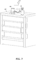
- the recovery cylinder 80 and the charge port 23 of the second heat source unit 10B are connected to each other, as illustrated in Fig. 7 , by the charge hose 70.
- the heat-source-side circuit 110 of the second heat source unit 10B and the recovery cylinder 80 are in communication with each other. Then, the second heat source unit 10B is operated to drive the compressor 11, and the refrigerant is transferred from the recovery cylinder 80 to the charge port 23 of the second heat source unit 10B. By closing the recovery cylinder 80 and detaching the charge hose 70 from the charge port 23 and the recovery cylinder 80, the charge port 23 is closed.
- the scale 61 measures the weight of the recovery cylinder 80 after the recovery of the recovered refrigerant into the recovery cylinder 80 and the weight of the recovery cylinder 80 after the transfer of the recovered refrigerant from the recovery cylinder 80 to the second heat source unit 10B and measures the weight of the recovered refrigerant from a difference between the weights of the recovery cylinder 80 before and after the transfer.
- the recovery cylinder 80 When the recovery cylinder 80 is used, it is sufficient if the total of the weight of the single refrigerant previously charged in the second heat source unit 10B and the weight of the mixed refrigerant including the recovered refrigerant and the added refrigerant is within a range of a proper gross weight of the refrigerants for the refrigeration cycle apparatus 1 after renewal.
- the weight of the first heat source unit 10A that is before and after the transfer of the refrigerant to the second heat source unit 10B are measured has been described; however, as illustrated in Fig. 8 , the weight of the second heat source unit 10B that is before and after the transfer of the refrigerant to the second heat source unit 10B may be measured.
- the weight of the second heat source unit 10B is measured by the scale 61.
- the scale 61 measures the recovered refrigerant transferred to the second heat source unit 10B by measuring the weight of the second heat source unit 10B before the recovered refrigerant is transferred to the second heat source unit 10B and after the recovered refrigerant is transferred to the second heat source unit 10B.
- the refrigerant of the utilization-side circuit 120 is transferred to the heat-source-side circuit 110 of the first heat source unit 10A through pump down operation.
- the high-pressure-side shutoff valve 21 is closed, and the first heat source unit 10A is operated to perform cooling.
- the high-pressure-side shutoff valve 21 is closed, and operation in which the heat-source-side heat exchanger 14 of the first heat source unit 10A functions as a condenser is performed.
- the pressure of the low-pressure-side shutoff valve 22 becomes sufficiently low, the low-pressure-side shutoff valve 22 is closed.
- the service port of the high-pressure-side shutoff valve 21 of the first heat source unit 10A and the charge port 23 of the second heat source unit 10B are connected to each other by the charge hose 70.
- the charge hose 70 being attached to the charge port 23 and the service port of the high-pressure-side shutoff valve 21, the heat-source-side circuit 110 of the first heat source unit 10A and the heat-source-side circuit 110 of the second heat source unit 10B are in communication with each other.
- the first heat source unit 10A is operated to drive the compressor 11, and the refrigerant is transferred through the service port of the high-pressure-side shutoff valve 21 of the first heat source unit 10A to the charge port 23 of the second heat source unit 10B.
- the charge port 23 and the service port of the high-pressure-side shutoff valve 21 are closed. Since the recovered refrigerant has been transferred in the second heat source unit 10B, the recovered refrigerant in the second heat source unit 10B is charged to the refrigeration cycle apparatus 1 as a result of the second heat source unit 10B being incorporated in the refrigeration cycle apparatus 1.
- a mass flow meter 62 may be used to measure the weight of the recovered refrigerant that is transferred from the first heat source unit 10A to the second heat source unit 10B.
- the mass flow meter 62 is included in the measurement system 60.
- the mass flow meter 62 is, for example, a Coriolis flow meter. Using the Coriolis flow meter makes it possible to measure the mass of the recovered refrigerant even when the refrigerant is transferred from the first heat source unit 10A to the second heat source unit 10B in a gas-liquid two-phase state.
- a measured value (kg) obtained by the mass flow meter 62 is nearly equal to the weight (kgf) of the recovered refrigerant.
- Measurement using the mass flow meter 62 can be performed in any of a case in which the refrigerant is transferred from the first heat source unit 10A to the second heat source unit 10B with the first heat source unit 10A connected to the power source 210, a case in which the refrigerant is transferred from the first heat source unit 10A to the second heat source unit 10B with the second heat source unit 10B connected to the power source 210, or a case in which the refrigerant is transferred from the first heat source unit 10A to the second heat source unit 10B via the recovery cylinder 80.
- the refrigerant charging method for the refrigeration cycle apparatus 1 described in the aforementioned embodiment it is preferable to further include a step of, before recovering the refrigerant from the first heat source unit 10A, operating the already installed refrigeration cycle apparatus 1 and heating the refrigerant in the refrigerant circuit 100.
- the circulating refrigerant is preferably regulated to be non-flammable.
- the mixed refrigerant is an R410A refrigerant and the single refrigerant is an R32 refrigerant
- pentafluoroethane is non-flammable
- the R32 refrigerant difluoromethane
- the circulating refrigerant has a possibility of having slight flammability.
- the mixture ratio of difluoromethane and pentafluoroethane at which the circulating refrigerant becomes non-flammable is previously examined, and the upper limit threshold of the mixture ratio of difluoromethane at which it can be judged to be non-flammable is determined in advance. Consequently, when an air conditioner after renewal is an apparatus intended for a non-flammable refrigerant, the circulating refrigerant is usable as it is. The circulating refrigerant is judged, from the measured weight of the recovered refrigerant and the weight of an R32 refrigerant to be replenished, to be non-flammable when the mixture ratio of difluoromethane occupying the circulating refrigerant is smaller than the upper limit threshold.
- the circulating refrigerant When the circulating refrigerant can be judged to be non-flammable, only the R32 refrigerant is replenished. If it is not possible to judge that the circulating refrigerant is non-flammable, charging is performed such that the circulating refrigerant becomes non-flammable by, for example, adding another refrigerant, such as pentafluoroethane.
- each of the first heat source unit 10A and the second heat source unit 10B is provided with the subcooling heat exchanger 15
- the first heat source unit 10A and/or the second heat source unit 10B may not be provided with the subcooling heat exchanger 15.
- each of the first heat source unit 10A and the second heat source unit 10B is provided with the oil regulator 19 has been described; however, the first heat source unit 10A and/or the second heat source unit 10B may not be provided with the oil regulator 19.
- each of the first heat source unit 10A and the second heat source unit 10B is provided with the refrigerant regulator 18; however, the first heat source unit 10A and/or the second heat source unit 10B may not be provided with the refrigerant regulator 18.
- each of the first heat source unit 10A and the second heat source unit 10B is provided with the oil separator 12 has been described; however, the first heat source unit 10A and/or the second heat source unit 10B may not be provided with the oil separator 12.
- an R32 refrigerant (an example of the first refrigerant), which is a single refrigerant, is charged in the second heat source unit 10B before the second heat source unit 10B is connected to the utilization units 50 to configure the refrigerant circuit 100; therefore, outside air is obstructed by the R32 refrigerant from entering the second heat source unit 10B.
- a foreign material and moisture can be suppressed from mixing with outside air and entering the second heat source unit 10B before incorporated in the refrigeration cycle apparatus 1.
- Such an effect can be obtained even when, for example, another single refrigerant, such as an R1234yf refrigerant is used as the single refrigerant, as an alternative to an R32 refrigerant.
- an R32 refrigerant which is a single refrigerant, is used as the first refrigerant.
- the first refrigerant may be a mixed refrigerant.
- a 410A refrigerant which is a mixed refrigerant, is used as the second refrigerant.
- the second refrigerant may be a single refrigerant.
- a single refrigerant which is the first refrigerant, having the absolute pressure more than or equal to the atmospheric pressure is charged in the second heat source unit 10B, and therefore, outside air does not easily enter the second heat source unit 10B.
- the first refrigerant having the absolute pressure more than or equal to the atmospheric pressure
- the absolute pressure of the R32 refrigerant (an example of the first refrigerant), which is a single refrigerant, charged in the second heat source unit 10B is less than 1 MPa, which is low, and therefore, compared with when a single refrigerant having a high pressure of 1 MPa or more is charged, it is possible to prevent entrance of outside air with a small amount of charging.
- the refrigerant charging method for the refrigeration cycle apparatus 1 of the aforementioned embodiment or in the second heat source unit 10B due to the components of the R410A refrigerant including difluoromethane, it is possible to use the R32 refrigerant charged in the second heat source unit 10B as it is, without extracting the R32 refrigerant, for the refrigerant circuit 100 after renewal including the second heat source unit 10B compatible with a mixed refrigerant of pentafluoroethane, which is the other component of the R410A refrigerant, and difluoromethane, and therefore, the time and labor in refrigerant charging are saved.
- the circulating refrigerant is non-flammable to use the circulating refrigerant as it is when the refrigeration cycle apparatus 1 after renewal is an apparatus intended for a non-flammable refrigerant, compared with when a flammable circulating refrigerant is used in the refrigerant circuit 100.
- the second heat source unit 10B is transported to the rooftop of the building 200, which is the installation location, with the R32 refrigerant (an example of the first refrigerant), which is a single refrigerant, charged therein. Therefore, outside air is obstructed by the single refrigerant from entering the second heat source unit 10B during transport. As a result, it is possible to avoid a foreign material, moisture, and the like from mixing with outside air and entering the second heat source unit 10B during transport. Moreover, there is no need to extract the R32 refrigerant when connecting the second heat source unit 10B to the refrigerant circuit 100, and therefore, time and labor in charging work are saved.
- the utilization units 50 and the connection pipes 81 and 82 configured the refrigerant circuit 100 that includes the first heat source unit 10A, the refrigerant circuit 100 being another refrigerant circuit that differs from the refrigerant circuit 100 including the second heat source unit 10B at the rooftop.
- the rooftop is a location where the second heat source unit 10B is to be connected to configure the refrigerant circuit 100.
- the utilization units 50 and the connection pipes 81 and 82 are connected to the second heat source unit 10B, which is another heat source unit other than the first heat source unit 10A.
- the second heat source unit 10B is included the refrigerant circuit 100 which is the other refrigerant circuit included the first heat source unit 10A.
- the recovered refrigerant recovered from the refrigerant circuit 100 including the first heat source unit 10A is charged as a mixed refrigerant (an example of the second refrigerant) to the refrigerant circuit 100 including the second heat source unit 10B.
- the recovered refrigerant is charged as a mixed refrigerant in the step S5 to the refrigerant circuit 100 including the second heat source unit 10B, and it is thus possible to reutilize the recovered refrigerant in the refrigerant circuit 100 and to effectively utilize the recovered refrigerant.
- the second heat source unit 10B of the aforementioned embodiment is for configuring the refrigerant circuit 100 of the refrigeration cycle apparatus 1 after renewal in which a refrigeration cycle is to be performed by a circulating refrigerant.
- the heat-source-side circuit 110 of the second heat source unit 10B is a circuit for configuring a portion of the refrigerant circuit 100 after renewal, and the second heat source unit 10B includes an R32 refrigerant (an example of the first refrigerant), which is a single refrigerant, charged in the heat-source-side circuit 110 that is before configuring a portion of the refrigerant circuit 100 after renewal.
- the second heat source unit 10B Due to the R32 refrigerant being thus charged to the second heat source unit 10B before the utilization units 50 and the second heat source unit 10B are connected to each other, outside air can be obstructed by the R32 refrigerant from entering the second heat source unit 10B. As a result, the second heat source unit 10B can avoid a foreign material, moisture, and the like from mixing with outside air and entering the refrigerant circuit 100 in the inner portion thereof.
- the first heat source unit 10A of an already installed refrigeration cycle apparatus in which a refrigeration cycle is to be performed by a circulating refrigerant is replaced with the second heat source unit 10B, and the renewed refrigeration cycle apparatus 1 is thereby obtained.
- the connection pipes 81 and 82 which are the connection pipes connected to the first heat source unit 10A, are connected to the second heat source unit 10B to thereby configure the refrigerant circuit 100 in which the circulation refrigerant that performs the refrigeration cycle flows.
- the connection pipes 81 and 82 of the already installed refrigeration cycle apparatus are used in the refrigerant circuit 100, and it is thus possible to reduce costs for obtaining the renewed refrigeration cycle apparatus 1, compared with when new connection pipes are used.
Landscapes
- Engineering & Computer Science (AREA)
- Physics & Mathematics (AREA)
- Mechanical Engineering (AREA)
- Thermal Sciences (AREA)
- General Engineering & Computer Science (AREA)
- Analytical Chemistry (AREA)
- Chemical & Material Sciences (AREA)
- Power Engineering (AREA)
- Other Air-Conditioning Systems (AREA)
- Compression-Type Refrigeration Machines With Reversible Cycles (AREA)
- Air Conditioning Control Device (AREA)
- Transition And Organic Metals Composition Catalysts For Addition Polymerization (AREA)
- Elimination Of Static Electricity (AREA)
Abstract
Description
- The present disclosure relates to a method of charging a refrigerant to a refrigerant circuit in which a refrigeration cycle is to be performed by a circulating refrigerant, a heat source unit for configuring a refrigerant circuit in which a refrigeration cycle is to be performed, and a refrigeration cycle apparatus.
- A refrigeration cycle apparatus including a refrigerant circuit in which a refrigeration cycle is to be performed is applied to an air conditioning apparatus, a boiler, and the like. As described in, for example, PTL 1 (
Japanese Laid-Open Patent Application No. 2009-222356 - However, it is required for the refrigeration cycle apparatus described in PTL 1 to transport an outdoor unit to the installation location of the refrigeration cycle apparatus when, for example, the outdoor unit, which is a heat source unit, is to be renewed. During transport of the outdoor unit, foreign materials, such as dust and oil, or moisture may enter the inside of the outdoor unit as a result of, for example, a plug being loosened.
- Accordingly, in a heat source unit for configuring such a refrigeration cycle apparatus, there is a subject of avoiding a foreign material and moisture from entering the heat source unit until the refrigeration cycle apparatus is configured.
- A refrigerant charging method according to a first aspect is a method of charging a refrigerant to a refrigerant circuit in which a refrigeration cycle is to be performed by a circulating refrigerant, the refrigerant circuit being configured by connecting a heat source unit and a utilization unit to each other, the method including: a step (a) of charging a first refrigerant to the heat source unit before connecting the heat source unit to the utilization unit to configure the refrigerant circuit; and a step (b) of connecting the heat source unit to the utilization unit and additionally charging a second refrigerant that differs from the first refrigerant to the refrigerant circuit to obtain the circulating refrigerant that includes the second refrigerant and the first refrigerant that is charged in the heat source unit.
- In the refrigerant charging method according to the first aspect, due to the first refrigerant being charged in the heat source unit before the heat source unit is connected to the utilization unit to configure the refrigerant circuit, outside air is obstructed by the first refrigerant from entering the heat source unit, and it is thus possible to avoid a foreign material and moisture from mixing with outside air and entering the heat source unit.
- A refrigerant charging method according to a second aspect is the refrigerant charging method according to the first aspect in which, in the step (a), the first refrigerant charged in the heat source unit has an absolute pressure that is more than or equal to an atmospheric pressure at 20°C in the heat source unit.
- In the refrigerant charging method according to the second aspect, due to the heat source unit being charged with the first refrigerant having the absolute pressure more than or equal to the atmospheric pressure, outside air does not easily enter the heat source unit, and it is thus possible to improve the effect of avoiding a foreign material, moisture, and the like from mixing with outside air and entering the heat source unit.
- A refrigerant charging method according to a third aspect is the refrigerant charging method according to the second aspect in which, in the step (a), the first refrigerant charged in the heat source unit has an absolute pressure that is less than 1 MPa at 35°C in the heat source unit.
- In the refrigerant charging method according to the third aspect, due to the absolute pressure of the first refrigerant charged in the heat source unit being less than 1 MPa, which is low, it is possible to prevent entrance of outside air with a small amount of charging, compared with when the first refrigerant that has a high pressure more than or equal to 1 MPa is charged.
- A refrigerant charging method according to a fourth aspect is the refrigerant charging method according to any of the first aspect to the third aspect in which the first refrigerant is an R32 refrigerant, and the second refrigerant includes an R410A refrigerant.
- In the refrigerant charging method according to the fourth aspect, due to the components of the R410A refrigerant including difluoromethane, it is possible to use the R32 refrigerant charged in the heat source unit as it is, without extracting the R32 refrigerant therefrom, with respect to the refrigerant circuit compatible with the second refrigerant including pentafluoroethane, which is the other component of the R410A refrigerant, and difluoromethane, and therefore, time and labor in refrigerant charging are saved.
- A refrigerant charging method according to a fifth aspect is the refrigerant charging method according to any of the first aspect to the fourth aspect in which the circulating refrigerant is non-flammable.
- In the refrigerant charging method according to the fifth aspect, due to the circulating refrigerant being non-flammable, it is possible to use the circulating refrigerant as it is when, for example, a refrigeration cycle apparatus after renewal is an apparatus intended for a non-flammable refrigerant.
- A refrigerant charging method according to a sixth aspect is the refrigerant charging method according to any of the first aspect to the fifth aspect, the method further including, after the step (a), a step (c) of transporting the heat source unit with the first refrigerant charged therein to a location where the heat source unit is to be connected to configure the refrigerant circuit.
- In the refrigerant charging method according to the sixth aspect, due to the heat source unit being transported with the first refrigerant charged therein to the installation location, outside air is obstructed by the first refrigerant from entering the heat source unit during transport, and it is thus possible to avoid a foreign material, moisture, and the like from mixing with outside air during transport and entering the heat source unit. Moreover, there is no need to extract the R32 refrigerant when the heat source unit is to be connected to the refrigerant circuit, and thus, time and labor in charging work are saved.
- A refrigerant charging method according to a seventh aspect is the refrigerant charging method according to the sixth aspect in which, before the step (b) is performed, a connection pipe connected to the utilization unit and/or the heat source unit is connected to another heat source unit other than the heat source unit at the location and configures another refrigerant circuit that differs from the refrigerant circuit, and in which, in the step (b), a recovered refrigerant recovered from the other refrigerant circuit is charged as the second refrigerant to the refrigerant circuit.
- In the refrigerant charging method according to the seventh aspect, due to the recovered refrigerant being charged as the second refrigerant to the refrigerant circuit in the step (b), it is possible to reutilize the recovered refrigerant in the refrigerant circuit and possible to effectively utilize the recovered refrigerant.
- A heat source unit according to an eighth aspect is a heat source unit for configuring a refrigerant circuit in which a refrigeration cycle is to be performed by a circulating refrigerant, the heat source unit including: a heat-source-side circuit for configuring a portion of the refrigerant circuit, and a first refrigerant charged in the heat-source-side circuit that is before configuring the portion of the refrigerant circuit, in which the heat-source-side circuit is configured to cause, in a state of being the portion of the refrigerant circuit, the circulating refrigerant to circulate in the refrigerant circuit, the circulating refrigerant including the first refrigerant and a second refrigerant that is charged to the refrigerant circuit.
- In the heat source unit according to the eighth aspect, due to the first refrigerant being charged in the heat source unit before the utilization unit and the heat source unit are connected to each other, outside air is obstructed by the first refrigerant from entering the heat source unit, and it is thus possible to avoid a foreign material, moisture, and the like from mixing with outside air and entering the heat source unit.
- A heat source unit according to a ninth aspect is the heat source unit according to the eighth aspect in which the first refrigerant has an absolute pressure that is more than or equal to an atmospheric pressure at 20°C in the heat-source-side circuit.
- In the heat source unit according to the ninth aspect, due to the heat source unit being charged with the first refrigerant having the absolute pressure more than or equal to the atmospheric pressure, outside air does not easily enter the heat-source-side circuit, and it is thus possible to improve the effect of avoiding a foreign material, moisture, and the like from mixing with outside air and entering the heat-source-side circuit.
- A heat source unit according to a tenth aspect is the heat source unit according to the eighth aspect or the ninth aspect in which the first refrigerant is an R32 refrigerant, and the second refrigerant is an R410A refrigerant.
- In the heat source unit according to the tenth aspect, due to the components of the R410A refrigerant including difluoromethane, it is possible to use the R32 refrigerant that is charged in the heat-source-side circuit as it is, without extracting the R32 refrigerant, with respect to the refrigerant circuit compatible with the second refrigerant including pentafluoroethane, which is the other component of the R410A refrigerant, and difluoromethane, and therefore, time and labor in connection of the heat source unit are saved.
- A renewed refrigeration cycle apparatus according to an eleventh aspect is a renewed refrigeration cycle apparatus that is an already installed refrigeration cycle apparatus in which a refrigeration cycle is to be performed by a circulating refrigerant, the renewed installed refrigeration cycle apparatus including a second heat source unit that replaces a first heat source unit of the already installed refrigeration cycle apparatus, in which the second heat source unit is the heat source unit according to any of the eighth aspect to the tenth aspect, and in which a connection pipe connected to the first heat source unit in the already installed refrigeration cycle apparatus is connected to the second heat source unit to thereby configure a refrigerant circuit in which the circulating refrigerant that performs the refrigeration cycle flows.
- In the renewed refrigeration cycle apparatus according to the eleventh aspect, due to the connection pipe of the already installed refrigeration cycle apparatus being used in the refrigerant circuit, it is possible to reduce costs for obtaining the apparatus, compared with when a new connection pipe is used.
-
-
Fig. 1 is a refrigerant circuit diagram illustrating an outline of the configuration of a refrigeration cycle apparatus according to an embodiment. -
Fig. 2 is a schematic diagram for describing transfer of a refrigerant from a first heat source unit to a second heat source unit. -
Fig. 3 is a schematic diagram for describing measurement of the weight of a refrigerant transferred from the first heat source unit to the second heat source unit. -
Fig. 4 is a flowchart illustrating an outline of a flow of a method of charging a refrigerant to a refrigeration cycle apparatus. -
Fig. 5 is a conceptual diagram for describing transport of the second heat source unit. -
Fig. 6 is a schematic diagram for describing measurement of the weight of a refrigerant in a modification IF. -
Fig. 7 is a schematic diagram for describing measurement of the weight of a refrigerant in the modification IF. -
Fig. 8 is a schematic diagram for describing measurement of the weight of a refrigerant in a modification 1G. -
Fig. 9 is a schematic diagram for describing measurement of the weight of a refrigerant in modification 1H. - In
Fig. 1 , an example of the configuration of a refrigeration cycle apparatus that is to be an object of a refrigerant charging method is illustrated. As illustrated inFig. 1 , a refrigeration cycle apparatus 1 is an apparatus in which a refrigeration cycle is to be performed by a refrigerant that circulates in arefrigerant circuit 100. The refrigeration cycle apparatus 1 repeats a cycle of compression of a refrigerant, heat radiation from the refrigerant, decompression expansion of the refrigerant, and heat absorption into the refrigerant. The refrigeration cycle apparatus 1 includes a firstheat source unit 10A or a secondheat source unit 10B switchable to have a function of heat radiation or to have a function of heat absorption in the refrigeration cycle, and autilization unit 50 connected to the firstheat source unit 10A or the secondheat source unit 10B. Here, the firstheat source unit 10A is a heat source unit before renewal, and the secondheat source unit 10B is a heat source unit after renewal. - The
utilization unit 50 cools an object by utilizing heat absorption of a refrigerant when the firstheat source unit 10A or the secondheat source unit 10B is a heat source whose heat is radiated from the refrigerant. Theutilization unit 50 heats an object by utilizing heat radiation of the refrigerant when the firstheat source unit 10A or the secondheat source unit 10B is a heat source whose heat is absorbed by the refrigerant. - The refrigeration cycle apparatus 1 is applicable to an air conditioning apparatus that performs cooling and heating. In this case, for example, the first
heat source unit 10A or the secondheat source unit 10B serves as an outdoor unit of the air conditioning apparatus, and theutilization unit 50 serves as an indoor unit of the air conditioning apparatus. Theutilization unit 50 that is the indoor unit cools or heats air in an air-conditioning object space to perform cooling or heating. Note that, although a case in which the refrigeration cycle apparatus 1 is applied to an air conditioning apparatus is presented as an example and described here, the refrigeration cycle apparatus is also applicable to other apparatuses, for example, a heat pump boiler, a refrigerator, and a cooling apparatus that cools inside a chamber. - In
Fig. 2 andFig. 3 , regarding a case in which the refrigeration cycle apparatus 1 is an air conditioning apparatus, an example in which the refrigeration cycle apparatus 1 is installed at abuilding 200 is illustrated. In the example illustrated inFig. 2 , the firstheat source unit 10A or the secondheat source unit 10B is installed at the rooftop of thebuilding 200. As illustrated inFig. 2 , a plurality ofutilization units 50 are installed in respective rooms to perform air conditioning of each room in thebuilding 200. - In
Fig. 2 andFig. 3 , the firstheat source unit 10A before renewal included in the already installed refrigeration cycle apparatus 1 and the secondheat source unit 10B that is planned to be included in the refrigeration cycle apparatus 1 after renewal are illustrated. In other words, the firstheat source unit 10A is an old heat source unit, and the secondheat source unit 10B is a new heat source unit. The already installed refrigeration cycle apparatus 1 has already been installed at thebuilding 200 and has an experience of performing a refrigeration cycle by circulating a refrigerant before renewal. A refrigerant is present in each of the firstheat source unit 10A and the plurality ofutilization units 50 included in the refrigeration cycle apparatus 1. Here, a refrigerant that is included in the inner portion of the refrigeration cycle apparatus 1 for the purpose of circulating in therefrigerant circuit 100 is referred to as a circulating refrigerant. - As described in the flowchart in
Fig. 4 , a refrigerant charging method, which will be described below, for the above-described refrigeration cycle apparatus 1 is configured to include a step S1 of charging a single refrigerant to the secondheat source unit 10B before connecting the secondheat source unit 10B to theutilization units 50 to configure therefrigerant circuit 100 and a step S6 of connecting the second heat source unit to theutilization units 50 to configure therefrigerant circuit 100 and additionally charging a mixed refrigerant to the refrigerant circuit to obtain a circulating refrigerant that includes the mixed refrigerant and the single refrigerant that is charged in the secondheat source unit 10B. - In the following description of an embodiment, a case in which the mixed refrigerant is an R410A refrigerant and the single refrigerant is an R32 refrigerant is presented as an example and described. The R410A refrigerant is a mixed refrigerant of difluoromethane and pentafluoroethane, and a recovered refrigerant is also a mixed refrigerant, as with the R410A refrigerant. The R32 refrigerant is a single refrigerant of fluoromethane and in coincidence with one of the components of R410A.
- A long period of use of the R410A refrigerant in the already installed refrigeration cycle apparatus 1 may change the mixture ratio of difluoromethane and pentafluoroethane with a lapse of time. The range of the change in the mixture ratio of difluoromethane and pentafluoroethane can be estimated, although including errors, through an experiment, a simulation, or the like. The already installed refrigeration cycle apparatus 1 in which the first
heat source unit 10A is incorporated has an allowable range in which operation is possible even when the mixture ratio of difluoromethane and pentafluoroethane occupying the circulating refrigerant changes from that in the initial R410A refrigerant. Similarly, the refrigeration cycle apparatus 1 after renewal including the secondheat source unit 10B also has an allowable range regarding the mixture ratio of difluoromethane and pentafluoroethane so as to be able to operate even when the mixture ratio of difluoromethane and pentafluoroethane is not the same, which is 1:1, as that in the R410A. - Accordingly, the refrigeration cycle apparatus 1 after renewal operates normally if the mixture ratio of difluoromethane and pentafluoroethane of the circulating refrigerant after the addition of the R32 refrigerant to the recovered refrigerant is within the allowable range of the refrigeration cycle apparatus 1 after renewal.
- As illustrated in
Fig. 5 , first, the R32 refrigerant prepared in acylinder 85 or the like is charged at acharge location 300, such as a factory, to the secondheat source unit 10B (step S1). With the R32 refrigerant charged therein, the secondheat source unit 10B is transported to the rooftop of thebuilding 200, which is a location where theutilization units 50 is to be connected to configure therefrigerant circuit 100, by using transport means 400, such as a truck and a crane. - The single refrigerant, which is the R32 refrigerant here, charged in the second
heat source unit 10B is preferably charged to an amount to have an absolute pressure that is more than or equal to the atmospheric pressure at 20°C in the secondheat source unit 10B. This is because, when the pressure inside a heat-source-side circuit 110 is more than or equal to the atmospheric pressure, entrance of outside air from outside of the secondheat source unit 10B toward inside of therefrigerant circuit 100 becomes difficult. The single refrigerant, which is the R32 refrigerant here, charged in the secondheat source unit 10B is preferably charged by an amount to have an absolute pressure that is less than 1 MPs at 35°C in the secondheat source unit 10B. Such a configuration makes it possible to prevent entrance of outside air with a small amount of charging. Further, the pressure of the single refrigerant charged in the secondheat source unit 10B is preferably less than 200 kPa at a gauge pressure at 20°C. Employing such a configuration makes it possible to prevent entrance of outside air with a smaller amount of charging. - In a state in which the circulating refrigerant of the refrigeration cycle apparatus 1 has been transferred to the first
heat source unit 10A through pump down operation, the firstheat source unit 10A is detached from the refrigeration cycle apparatus 1 at the rooftop of the building 200 (step S2). When the firstheat source unit 10A is to be detached, a high-pressure-side shutoff valve 21 and a low-pressure-side shutoff valve 22 of the firstheat source unit 10A are closed. - Next, the second
heat source unit 10B is incorporated in the refrigeration cycle apparatus 1 (step S3). With respect to the refrigeration cycle apparatus 1 after renewal in which the secondheat source unit 10B is incorporated, for example, airtightness of the refrigeration cycle apparatus 1 is inspected, and, after the airtightness of the refrigeration cycle apparatus 1 is confirmed, the refrigeration cycle apparatus 1 is evacuated by a vacuum pump. - In
Fig. 2 , a state in which the refrigerant is transferred from the firstheat source unit 10A to the secondheat source unit 10B is schematically illustrated. In a state of being incorporated in the refrigeration cycle apparatus 1 that is after renewal, the secondheat source unit 10B is connected to apower source 210 and in an operable state. The firstheat source unit 10A and the secondheat source unit 10B are connected to each other by acharge hose 70. In response to the operation of the secondheat source unit 10B, the R410A refrigerant is transferred from the firstheat source unit 10A through thecharge hose 70 to the secondheat source unit 10B. Through this transfer of the refrigerant from the firstheat source unit 10A to the secondheat source unit 10B, a recovered refrigerant is obtained (step S4). At this time, the firstheat source unit 10A is, for example, in a state of being temporarily placed at the rooftop of thebuilding 200 and is not connected to thepower source 210. - In
Fig. 3 , a state in which the weight of the recovered refrigerant recovered in the secondheat source unit 10B from the firstheat source unit 10A is measured is illustrated. The weight of the firstheat source unit 10A is measured by ascale 61. Thescale 61 measures the recovered refrigerant recovered from the firstheat source unit 10A by measuring the weight of the firstheat source unit 10A both of before the recovered refrigerant is transferred from the firstheat source unit 10A and after the recovered refrigerant is transferred from the firstheat source unit 10A. The weight of the recovered refrigerant can be calculated by subtracting a measured value obtained by thescale 61 regarding the firstheat source unit 10A that is before transfer of the recovered refrigerant from the firstheat source unit 10A from a measured value obtained by thescale 61 regarding the firstheat source unit 10A that is after transfer of the recovered refrigerant from the firstheat source unit 10A (step S5). - As a result of the second
heat source unit 10B to which the recovered refrigerant has been transferred being incorporated in the refrigeration cycle apparatus 1, transfer of the recovered refrigerant to the refrigeration cycle apparatus 1 is completed. The recovered refrigerant (a mixed refrigerant of difluoromethane and pentafluoroethane) that has been recovered is thus additionally charged to the refrigeration cycle apparatus 1, and a circulating refrigerant including the recovered refrigerant, which is a mixed refrigerant, and the R32 refrigerant (the single refrigerant previously charged in the secondheat source unit 10B) is obtained (step S6). - The gross weight of the refrigerants proper for the refrigeration cycle apparatus 1 after renewal in which the second
heat source unit 10B is incorporated can be previously calculated by using data of the already installed refrigeration cycle apparatus 1 in which the firstheat source unit 10A is incorporated. It is possible to obtain the weight of a lacking refrigerant and to determine the charge amount of the R32 refrigerant by subtracting the weight of the recovered refrigerant measured by ameasurement system 60 in step S4 from the gross weight of the refrigerants proper for the refrigeration cycle apparatus 1 after renewal. Since an already charged amount of the R32 refrigerant is present in the secondheat source unit 10B in the transport step, it is sufficient to add an additional R32 refrigerant of an amount obtained by subtracting the already charged amount from the amount of the lacking refrigerant. When the additional R32 refrigerant is to be thus added, the additional R32 refrigerant may be added to the recovered refrigerant. When the gross weight of the refrigerants proper for the refrigeration cycle apparatus 1 after renewal is set in a prescribed range, calculation may be performed by using, for example, a median value of the prescribed range. When the total weight of the R32 refrigerant previously charged in the secondheat source unit 10B and the recovered refrigerant is within the prescribed range, it is also possible to take a measure of adding no additional refrigerant. - The refrigerant charging work from the step S2 to the step S6 described above is performed at, for example, a local site. Here, performing the refrigerant charging work from the step S2 to the step S6 at a local site means that the recovered refrigerant is not taken back to facilities, such as a factory, and the recovered refrigerant as it is or treated at the installation location of the refrigeration cycle apparatus 1 is recharged to the refrigeration cycle apparatus 1 after renewal. In the above-described case, the work from the step S2 to the step S6 is performed, for example, at the rooftop of the
building 200. When the refrigerant charging work from the step S2 to the step S6 is to be performed at a local site, the refrigerant charging work is preferably performed within one day and is more preferably performed during the daytime of one day. This is because an environmental change is small, a work object is easily visually recognized, and leakage of refrigerant and mixing of a foreign material into the refrigeration cycle apparatus 1 are easily prevented. - In the refrigeration cycle apparatus 1 illustrated in
Fig. 1 , one firstheat source unit 10A or one secondheat source unit 10B and a plurality of theutilization units 50 are connected byconnection pipes side circuit 110 in the firstheat source unit 10A or the secondheat source unit 10B and a utilization-side circuit 120 in eachutilization unit 50 are connected to each other, thereby configuring therefrigerant circuit 100. In the refrigeration cycle apparatus 1, circulation of the refrigerant in therefrigerant circuit 100 causes a vapor compression refrigeration cycle to repeat. An example in which the refrigeration cycle apparatus 1 is applied to an air conditioning apparatus will be described here. - To simplify the description, a case in which the first
heat source unit 10A before renewal and the secondheat source unit 10B after renewal have the same configuration will be described here; however, the technology according to the present disclosure is applicable, even when the configurations thereof are not same. For example, as illustrated inFig. 1 , each of the firstheat source unit 10A and the secondheat source unit 10B includes acompressor 11, anoil separator 12, a four-way valve 13, a heat-source-side heat exchanger 14, asubcooling heat exchanger 15, anaccumulator 16, arefrigerant regulator 18, anoil regulator 19, a heat-source-side fan 20, the high-pressure-side shutoff valve 21, the low-pressure-side shutoff valve 22, acharge port 23, afirst expansion valve 25a to athird expansion valve 25c, a firstelectromagnetic valve 26a to a sixthelectromagnetic valve 26f, afirst check valve 27a to afourth check valve 27d, a firstpressure regulating valve 28a to a thirdpressure regulating valve 28c, acapillary tube 29, a plurality offilters 30, and astrainer 31. - The heat-source-
side heat exchanger 14 is, for example, a fin-and-tube heat exchanger and exchanges heat between air and a refrigerant. For example, a plate heat exchanger is usable as thesubcooling heat exchanger 15. The firstelectromagnetic valve 26a to the sixthelectromagnetic valve 26f each have a function of opening and closing a flow path. The firstpressure regulating valve 28a to the thirdpressure regulating valve 28c each have a function of keeping the pressure of the refrigerant on the upstream side at a prescribed absolute pressure that is previously determined. The tips of the arrows given to the firstpressure regulating valve 28a to the thirdpressure regulating valve 28c indicate the downstream side of the firstpressure regulating valve 28a to the thirdpressure regulating valve 28c. Thefilters 30 each have a function of removing a foreign material from the refrigerant that passes therethrough. Thestrainer 31 has a function of removing a solid component from the refrigerant. - The discharge side of the
compressor 11 is connected to the first port of the four-way valve 13 via theoil separator 12 and afirst check valve 27a. The refrigerant discharged from thecompressor 11 is separated from the oil at theoil separator 12 and flows toward the first port of the four-way valve 13. The second port of the four-way valve 13 is connected to one entrance of the heat-source-side heat exchanger 14, the third port of the four-way valve 13 is connected to an inlet of theaccumulator 16, and the fourth port of the four-way valve 13 is connected to the low-pressure-side shutoff valve 22. In the four-way valve 13, the first port and the second port are in communication with each other while the third port and the fourth port are in communication with each other, as indicated by solid lines, during cooling operation, and the first port and the fourth port are in communication with each other while the second port and the third port are in communication with each other, as indicated by broken lines, during heating operation. - The other entrance of the heat-source-
side heat exchanger 14 is connected to one end of thefirst expansion valve 25a and connected to the high-pressure-side shutoff valve 21 via thefirst expansion valve 25a. Thesubcooling heat exchanger 15 is installed between the other end of thefirst expansion valve 25a and the high-pressure-side shutoff valve 21. Thefirst expansion valve 25a is provided on the liquid side of the heat-source-side heat exchanger 14 and able to regulate the degree of decompression of the refrigerant that passes therethrough. Thesubcooling heat exchanger 15, asubcooling circuit 32a, and asecond expansion valve 25b constitute asubcooling portion 32. Thesubcooling circuit 32a diverges from a diverging point P1 at a part extending from the other end of thefirst expansion valve 25a toward the high-pressure-side shutoff valve 21 and merges, through thesubcooling heat exchanger 15, with a merging point P2 between the four-way valve 13 and theaccumulator 16. Thesecond expansion valve 25b provided between the diverging point P1 and thesubcooling heat exchanger 15 is able to regulate the degree of decompression of the refrigerant that passes through thesubcooling circuit 32a. Thesubcooling heat exchanger 15 causes heat to be exchanged between the refrigerant that flows between the diverging point P1 and the high-pressure-side shutoff valve 21 and the refrigerant that flows from the diverging point P1 toward the merging point P2 in thesubcooling circuit 32a. - A diverging point P3, the first
electromagnetic valve 26a, a merging point P4, and the second check valve 27b are provided in this order from thesubcooling heat exchanger 15 toward the merging point P2 in thesubcooling circuit 32a. The diverging point P1 and the merging point P4 are connected to each other via the firstpressure regulating valve 28a, and the refrigerant flows from the diverging point P1 toward the merging point P4. The diverging point P3 is connected to an injection port of thecompressor 11. Accordingly, an intermediate-pressure refrigerant decompressed at thesecond expansion valve 25b exits from thesubcooling heat exchanger 15, diverges on the upstream of the firstelectromagnetic valve 26a, and flows into the injection port of thecompressor 11. - One outlet of the
accumulator 16 is directly connected to the suction side of thecompressor 11 to return a gas refrigerant to the suction side of thecompressor 11, and the other outlet of theaccumulator 16 is connected for oil-returning to the suction side of thecompressor 11 via thefilters 30 and a secondelectromagnetic valve 26b. Between the suction side of thecompressor 11 and theoil separator 12, a path that passes thefilters 30, a thirdelectromagnetic valve 26c, and thecapillary tube 29 is formed to return the separated oil to thecompressor 11. - One entrance of the
refrigerant regulator 18 is connected to the suction side of thecompressor 11 via thethird expansion valve 25c. Therefrigerant regulator 18 is a device that regulates the amount of the refrigerant that flows in therefrigerant circuit 100. The other entrance of therefrigerant regulator 18 is connected to the merging point P2 via the secondpressure regulating valve 28b. The outflow side of thefirst check valve 27a is connected to the other entrance of therefrigerant regulator 18 via the fourthelectromagnetic valve 26d and thethird check valve 27c. Therefrigerant regulator 18 has a function of keeping the amount of the refrigerant that flows in therefrigerant circuit 100 to be constant. - One entrance of the
oil regulator 19 is connected to the suction side of thecompressor 11 via the sixthelectromagnetic valve 26f. The other entrance of theoil regulator 19 is connected to the merging point P2 via the thirdpressure regulating valve 28c. The outflow side of thefirst check valve 27a is connected to the other entrance of theoil regulator 19 via the fifthelectromagnetic valve 26e and thefourth check valve 27d. Theoil regulator 19 has a function of keeping the amount of oil supplied to therefrigerant circuit 100 to be constant. - The heat-source-
side fan 20 is disposed at the heat-source-side heat exchanger 14. The heat-source-side fan 20 causes an airflow for accelerating heat exchange to be generated in the heat-source-side heat exchanger 14. - The
filters 30 are provided between theoil separator 12 and thefirst check valve 27a, between the heat-source-side heat exchanger 14 and thefirst expansion valve 25a, between thesubcooling heat exchanger 15 and the high-pressure-side shutoff valve 21, between the fourth port of the four-way valve 13 and the low-pressure-side shutoff valve 22, between the other outlet of theaccumulator 16 and the secondelectromagnetic valve 26b, between theoil separator 12 and the thirdelectromagnetic valve 26c, between thethird expansion valve 25c and therefrigerant regulator 18, and between theoil regulator 19 and the sixthelectromagnetic valve 26f. Thestrainer 31 is provided between theoil regulator 19 and the third pressure regulating valve 28. Thecharge port 23 is provided between thethird expansion valve 25c and thefilters 30. - As illustrated in
Fig. 1 , each of theutilization units 50 includes, for example, a utilization-side heat exchanger 51, a utilization-side expansion valve 52, and a utilization-side fan 53. The utilization-side heat exchanger 51 is, for example, a fin-and-tube heat exchanger and causes heat to be exchanged between air and a refrigerant. The utilization-side expansion valve 52 and the utilization-side heat exchanger 51 are series connected between the liquid-side connection pipe 81 and the gas-side connection pipe 82. The utilization-side expansion valve 52 and the utilization-side heat exchanger 51 are disposed in the order of the utilization-side expansion valve 52 and the utilization-side heat exchanger 51 from the liquid-side connection pipe 81 toward the gas-side connection pipe 82. The utilization-side fan 53 is disposed at each utilization-side heat exchanger 51. The utilization-side fan 53 causes an airflow for accelerating heat exchange to be generated in the utilization-side heat exchanger 51. The plurality ofutilization units 50 parallel connected between the liquid-side connection pipe 81 and the gas-side connection pipe 82 constitute the utilization-side circuit 120. - In cooling operation, the refrigeration cycle apparatus 1 causes the four-
way valve 13 to be in the state indicated by the solid lines, in other words, in a state in which the first port and the second port are in communication each other while the third port and the fourth port are in communication with each other. In the refrigeration cycle performed in cooling operation, the heat-source-side heat exchanger 14 functions as a radiator, and the utilization-side heat exchanger 51 functions as an evaporator. The refrigerant discharged from thecompressor 11 successively circulates in the heat-source-side heat exchanger 14, the utilization-side expansion valves 52, and the utilization-side heat exchangers 51 and repeats the vapor compression refrigeration cycle of compression, condensation, expansion, and evaporation. - The refrigeration cycle apparatus 1 controls the operation frequency of the
compressor 11 to cause the evaporation pressure or the evaporation temperature in the utilization-side heat exchanger 51 to be a target pressure or a target evaporation temperature and controls the valve opening degree of each utilization-side expansion valve 52 to cause the degree of superheating of the refrigerant that flows on the gas side of the utilization-side heat exchanger 51 to be a target degree of superheating. In cooling operation, thefirst expansion valve 25a is in the fully opened state. The refrigeration cycle apparatus 1 regulates the opening degree of thesecond expansion valve 25b to cause the degree of superheating of the refrigerant that has exited from thesubcooling heat exchanger 15 to be a target degree of superheating. When a prescribed condition is satisfied, the refrigeration cycle apparatus 1 causes the refrigerant that flows in thesubcooling circuit 32a to exchange heat in thesubcooling heat exchanger 15 with the refrigerant that flows between the diverging point P1 and the high-pressure-side shutoff valve 21 and to become a gas refrigerant having an intermediate pressure and supplies, through the injection port, the refrigerant to a compression chamber in the middle of compression of the compression mechanism of thecompressor 11. Thecompressor 11 that has been supplied with the gas refrigerant having the intermediate pressure can decrease the discharge temperature, compared with when injection of the gas refrigerant is not performed. - In heating operation, the refrigeration cycle apparatus 1 causes the four-
way valve 13 to be in the state indicated by the broken lines, in other words, in a state in which the first port and the fourth port are in communication with each other while the second port and the third port are in communication with each other. In the refrigeration cycle performed in heating operation, the heat-source-side heat exchanger 14 functions as an evaporator, and the utilization-side heat exchanger 51 functions as a radiator. The refrigerant discharged from thecompressor 11 successively circulates in the utilization-side heat exchanger 51, thefirst expansion valve 25a, and the heat-source-side heat exchanger 14 and repeats the vapor compression refrigeration cycle of compression, condensation, expansion, and evaporation. - In heating operation, the
second expansion valve 25b is in a fully closed state. The refrigeration cycle apparatus 1 controls the operation frequency of thecompressor 11 to cause the condensation temperature in the utilization-side heat exchanger 51 to be a target condensation temperature and controls the valve opening degree of the utilization-side expansion valve 52 to cause the degree of subcooling of the refrigerant that flows on the liquid side of the utilization-side heat exchanger 51 to be a target degree of subcooling. The refrigeration cycle apparatus 1 controls the valve opening degree of thefirst expansion valve 25a to cause the degree of superheating of the refrigerant that flows on the gas side of the heat-source-side heat exchanger 14 to be a target degree of superheating. - The
measurement system 60 includes thescale 61, which is illustrated inFig. 3 . Thescale 61 is, for example, a platform weighing scale or a crane weighing scale. Thescale 61 has a function capable of measuring the weight of the firstheat source unit 10A or the secondheat source unit 10B and has resolving power sufficient for detecting the weight of the refrigerant. - In the transfer of the refrigerant from the first
heat source unit 10A to the secondheat source unit 10B, for example, with the firstheat source unit 10A being incorporated in the refrigeration cycle apparatus 1 and being in an operable state, the refrigerant of the utilization-side circuit 120 is transferred to the heat-source-side circuit 110 of the firstheat source unit 10A through pump down operation. Then, the high-pressure-side shutoff valve 21 and the low-pressure-side shutoff valve 22 of the firstheat source unit 10A are closed. In the state in which the high-pressure-side shutoff valve 21 and the low-pressure-side shutoff valve 22 of the firstheat source unit 10A are closed after the pump down operation, the firstheat source unit 10A is detached and made to be in a temporarily placed state. In the pump down operation, for example, the high-pressure-side shutoff valve 21 is closed, and the firstheat source unit 10A is operated to perform cooling. The high-pressure-side shutoff valve 21 is closed, and operation in which the heat-source-side heat exchanger 14 of the firstheat source unit 10A functions as a condenser is performed. When the pressure of the low-pressure-side shutoff valve 22 becomes sufficiently low, the low-pressure-side shutoff valve 22 is closed. - After the first
heat source unit 10A is detached from the refrigeration cycle apparatus 1, the secondheat source unit 10B is incorporated in the refrigeration cycle apparatus 1. Then, as illustrated inFig. 2 , a service port of the high-pressure-side shutoff valve 21 of the firstheat source unit 10A and thecharge port 23 of the secondheat source unit 10B are connected to each other by thecharge hose 70. Here, a means of transferring the refrigerant includes thecharge hose 70. The secondheat source unit 10B is operated to drive thecompressor 11, and the refrigerant is transferred through the service port of the high-pressure-side shutoff valve 21 of the firstheat source unit 10A into thecharge port 23 of the secondheat source unit 10B. When the secondheat source unit 10B is to be operated to drive thecompressor 11, thethird expansion valve 25c is closed, cooling operation is performed, and the recovered refrigerant is sucked along a path in which the recovered refrigerant is sucked from therefrigerant regulator 18 by thecompressor 11 through theaccumulator 16. By detaching thecharge hose 70 from thecharge port 23 and the service port of the high-pressure-side shutoff valve 21, thecharge port 23 and the service port of the high-pressure-side shutoff valve 21 are closed. - In the aforementioned embodiment, a case in which both of the first
heat source unit 10A and the secondheat source unit 10B of the refrigeration cycle apparatus 1 are configured such that heat radiation and heat absorption of the refrigeration cycle are switchable has been described; however, the refrigeration cycle apparatus 1 is not limited to having such a configuration. In the refrigeration cycle apparatus 1, for example, the firstheat source unit 10A or the secondheat source unit 10B may be an exclusive machine that functions as a heat source whose heat is radiated from the refrigerant, and theutilization units 50 may be exclusive machines each function as a device whose heat is absorbed by the refrigerant. In this case, when the refrigeration cycle apparatus 1 is an air conditioning apparatus, the exclusive machine is a machine exclusive for cooling. In the refrigeration cycle apparatus 1, for example, the firstheat source unit 10A or the secondheat source unit 10B may be an exclusive machine that functions as a heat source whose heat is absorbed by the refrigerant, and theutilization units 50 may be exclusive machines each function as a device whose heat is radiated from the refrigerant. In this case, when the refrigeration cycle apparatus 1 is an air conditioning apparatus, the exclusive machine is a machine exclusive for heating. - In the aforementioned embodiment, a case in which the first
heat source unit 10A of the refrigeration cycle apparatus 1 is renewed has been described; however, the technology of the present disclosure is also applicable to a case in which the refrigeration cycle apparatus 1 is newly installed. When the refrigeration cycle apparatus 1 is to be newly installed, the steps S2, S4, and S5, in which the refrigerant is recovered, are omitted, and the steps S1, S3, and S6 are included in the refrigerant charging method. Accordingly, in the case of new installation, the recovered refrigerant is not available at a local site, and thus, a mixed refrigerant of an R410A refrigerant, an R452B refrigerant, or the like that has been transported from a location other than the local site is newly charged. - In the aforementioned embodiment, a case in which the mixed refrigerant recovered from the already installed refrigeration cycle apparatus 1 includes the R410A refrigerant and in which the single refrigerant is the R32 refrigerant has been described; however, the combination of the mixed refrigerant and the single refrigerant usable in the refrigeration cycle apparatus 1 is not limited thereto. For example, the mixed refrigerant recovered from the already installed refrigeration cycle apparatus 1 may be an R452B, and the single refrigerant may be an R32 refrigerant or an R1234yf refrigerant.
- When the recovered refrigerant including the R410A refrigerant is lacking with respect to the gross refrigerant amount of the refrigeration cycle apparatus 1 after renewal, the refrigerant that is further added, in addition to the single refrigerant previously charged in the second
heat source unit 10B, is not limited to the R32 refrigerant and may be, for example, an R410A refrigerant, an R125 refrigerant, or an R1234yf refrigerant. - In the aforementioned embodiment, the refrigeration cycle apparatus 1 of a multi type in which the refrigeration cycle apparatus 1 includes the plurality of
utilization units 50 has been described. A refrigeration cycle apparatus to which the technology of the present disclosure is applicable is, however, not limited to a multi-type refrigeration cycle apparatus. The technology of the present disclosure is also applicable to, for example, a refrigeration cycle apparatus of a pair type in which one utilization unit is connected to one heat source unit. - The number of heat source units connected to the refrigeration cycle apparatus is not limited to one, and a plurality of heat source units may be connected thereto. For example, when the refrigeration cycle apparatus includes two first heat source units, the recovered refrigerant may be transferred to two second heat source units that are intended to replace two first heat source units, and the weight of the two second heat source units after the transfer may be measured by the
measurement system 60 to thereby detect the weight of the recovered refrigerant. - In the aforementioned embodiment, a case in which the
compressor 11 of the firstheat source unit 10A is used as a power source of the transfer of the refrigerant has been described. The power source of the transfer of the refrigerant is, however, not limited to thecompressor 11 of the firstheat source unit 10A. For example, a refrigerant recovering device that includes a compressor therein may be used for the transfer of the refrigerant. - In the aforementioned embodiment, a case in which the refrigerant is directly transferred from the first
heat source unit 10A to the secondheat source unit 10B has been described; however, as illustrated inFig. 6 , the refrigerant may be once transferred from the firstheat source unit 10A to arecovery cylinder 80, and then, the refrigerant may be transferred from therecovery cylinder 80 to the secondheat source unit 10B. In this case, it may be configured such that thescale 61 measures the weight of therecovery cylinder 80 before the recovery of the recovered refrigerant into therecovery cylinder 80 and the weight of therecovery cylinder 80 after the recovery of the recovered refrigerant into therecovery cylinder 80 and measures the weight of the recovered refrigerant from a difference between the weights of therecovery cylinder 80 before and after the recovery. - When the
recovery cylinder 80 is to be thus used, for example, if the firstheat source unit 10A is connected to thepower source 210 and operable, the refrigerant of the utilization-side circuit 120 is transferred to the heat-source-side circuit 110 of the firstheat source unit 10A through pump down operation. The service port of the high-pressure-side shutoff valve 21 of the firstheat source unit 10A and therecovery cylinder 80 are connected to each other by thecharge hose 70. As a result of thecharge hose 70 being attached to the service port of the high-pressure-side shutoff valve 21 and therecovery cylinder 80, the heat-source-side circuit 110 of the firstheat source unit 10A and therecovery cylinder 80 are in communication with each other. Then, the firstheat source unit 10A is operated to drive thecompressor 11, and the refrigerant is transferred through the service port of the high-pressure-side shutoff valve 21 of the firstheat source unit 10A to therecovery cylinder 80. By closing therecovery cylinder 80 and detaching thecharge hose 70 from the service port of the high-pressure-side shutoff valve 21 and therecovery cylinder 80, the service port of the high-pressure-side shutoff valve 21 is closed. - With respect to the refrigeration cycle apparatus 1 after the second
heat source unit 10B is incorporated therein, for example, airtightness of the refrigeration cycle apparatus 1 is inspected, and, after the airtightness of the refrigeration cycle apparatus 1 is confirmed, the refrigeration cycle apparatus 1 is evacuated by a vacuum pump. When the recovered refrigerant is to be transferred from therecovery cylinder 80 to the secondheat source unit 10B incorporated in the refrigeration cycle apparatus 1, therecovery cylinder 80 and thecharge port 23 of the secondheat source unit 10B are connected to each other, as illustrated inFig. 7 , by thecharge hose 70. As a result of thecharge hose 70 being attached to thecharge port 23 and therecovery cylinder 80, the heat-source-side circuit 110 of the secondheat source unit 10B and therecovery cylinder 80 are in communication with each other. Then, the secondheat source unit 10B is operated to drive thecompressor 11, and the refrigerant is transferred from therecovery cylinder 80 to thecharge port 23 of the secondheat source unit 10B. By closing therecovery cylinder 80 and detaching thecharge hose 70 from thecharge port 23 and therecovery cylinder 80, thecharge port 23 is closed. - It may be configured such that the
scale 61 measures the weight of therecovery cylinder 80 after the recovery of the recovered refrigerant into therecovery cylinder 80 and the weight of therecovery cylinder 80 after the transfer of the recovered refrigerant from therecovery cylinder 80 to the secondheat source unit 10B and measures the weight of the recovered refrigerant from a difference between the weights of therecovery cylinder 80 before and after the transfer. - When the
recovery cylinder 80 is used, it is sufficient if the total of the weight of the single refrigerant previously charged in the secondheat source unit 10B and the weight of the mixed refrigerant including the recovered refrigerant and the added refrigerant is within a range of a proper gross weight of the refrigerants for the refrigeration cycle apparatus 1 after renewal. - In the aforementioned embodiment, a case in which the weight of the first
heat source unit 10A that is before and after the transfer of the refrigerant to the secondheat source unit 10B are measured has been described; however, as illustrated inFig. 8 , the weight of the secondheat source unit 10B that is before and after the transfer of the refrigerant to the secondheat source unit 10B may be measured. The weight of the secondheat source unit 10B is measured by thescale 61. Thescale 61 measures the recovered refrigerant transferred to the secondheat source unit 10B by measuring the weight of the secondheat source unit 10B before the recovered refrigerant is transferred to the secondheat source unit 10B and after the recovered refrigerant is transferred to the secondheat source unit 10B. It is possible to calculate the weight of the recovered refrigerant by subtracting a measured value obtained by thescale 61 regarding the secondheat source unit 10B that is before the transfer of the recovered refrigerant to the secondheat source unit 10B from a measured value obtained by thescale 61 regarding the secondheat source unit 10B that is after the transfer of the recovered refrigerant to the secondheat source unit 10B. - In the transfer of the refrigerant from the first
heat source unit 10A to the secondheat source unit 10B, for example, when the firstheat source unit 10A is connected to thepower source 210 and operable, the refrigerant of the utilization-side circuit 120 is transferred to the heat-source-side circuit 110 of the firstheat source unit 10A through pump down operation. For example, the high-pressure-side shutoff valve 21 is closed, and the firstheat source unit 10A is operated to perform cooling. The high-pressure-side shutoff valve 21 is closed, and operation in which the heat-source-side heat exchanger 14 of the firstheat source unit 10A functions as a condenser is performed. When the pressure of the low-pressure-side shutoff valve 22 becomes sufficiently low, the low-pressure-side shutoff valve 22 is closed. The service port of the high-pressure-side shutoff valve 21 of the firstheat source unit 10A and thecharge port 23 of the secondheat source unit 10B are connected to each other by thecharge hose 70. As a result of thecharge hose 70 being attached to thecharge port 23 and the service port of the high-pressure-side shutoff valve 21, the heat-source-side circuit 110 of the firstheat source unit 10A and the heat-source-side circuit 110 of the secondheat source unit 10B are in communication with each other. Then, the firstheat source unit 10A is operated to drive thecompressor 11, and the refrigerant is transferred through the service port of the high-pressure-side shutoff valve 21 of the firstheat source unit 10A to thecharge port 23 of the secondheat source unit 10B. By detaching thecharge hose 70 from thecharge port 23 and the service port of the high-pressure-side shutoff valve 21, thecharge port 23 and the service port of the high-pressure-side shutoff valve 21 are closed. Since the recovered refrigerant has been transferred in the secondheat source unit 10B, the recovered refrigerant in the secondheat source unit 10B is charged to the refrigeration cycle apparatus 1 as a result of the secondheat source unit 10B being incorporated in the refrigeration cycle apparatus 1. - In the embodiment and the modifications mentioned above, a case in which the
scale 61 is used to measure the weight of the recovered refrigerant has been described; however, as illustrated inFig. 9 , amass flow meter 62 may be used to measure the weight of the recovered refrigerant that is transferred from the firstheat source unit 10A to the secondheat source unit 10B. In this case, themass flow meter 62 is included in themeasurement system 60. Themass flow meter 62 is, for example, a Coriolis flow meter. Using the Coriolis flow meter makes it possible to measure the mass of the recovered refrigerant even when the refrigerant is transferred from the firstheat source unit 10A to the secondheat source unit 10B in a gas-liquid two-phase state. Considering that a difference of gravitational acceleration on the earth is minute, it is treated in the present disclosure such that a measured value (kg) obtained by themass flow meter 62 is nearly equal to the weight (kgf) of the recovered refrigerant. Measurement using themass flow meter 62 can be performed in any of a case in which the refrigerant is transferred from the firstheat source unit 10A to the secondheat source unit 10B with the firstheat source unit 10A connected to thepower source 210, a case in which the refrigerant is transferred from the firstheat source unit 10A to the secondheat source unit 10B with the secondheat source unit 10B connected to thepower source 210, or a case in which the refrigerant is transferred from the firstheat source unit 10A to the secondheat source unit 10B via therecovery cylinder 80. - In the refrigerant charging method for the refrigeration cycle apparatus 1 described in the aforementioned embodiment, it is preferable to further include a step of, before recovering the refrigerant from the first
heat source unit 10A, operating the already installed refrigeration cycle apparatus 1 and heating the refrigerant in therefrigerant circuit 100. - In the refrigerant charging method for the refrigeration cycle apparatus 1, when the mixed refrigerant and the single refrigerant are mixed together during charging to the refrigeration cycle apparatus 1 after renewal and become a circulating refrigerant, the circulating refrigerant is preferably regulated to be non-flammable.
- For example, when the mixed refrigerant is an R410A refrigerant and the single refrigerant is an R32 refrigerant, while pentafluoroethane is non-flammable, the R32 refrigerant (difluoromethane) has flammability, even though slightly; therefore, when the ratio of difluoromethane occupying the circulating refrigerant after charging increases, the circulating refrigerant has a possibility of having slight flammability. Thus, the mixture ratio of difluoromethane and pentafluoroethane at which the circulating refrigerant becomes non-flammable is previously examined, and the upper limit threshold of the mixture ratio of difluoromethane at which it can be judged to be non-flammable is determined in advance. Consequently, when an air conditioner after renewal is an apparatus intended for a non-flammable refrigerant, the circulating refrigerant is usable as it is. The circulating refrigerant is judged, from the measured weight of the recovered refrigerant and the weight of an R32 refrigerant to be replenished, to be non-flammable when the mixture ratio of difluoromethane occupying the circulating refrigerant is smaller than the upper limit threshold. When the circulating refrigerant can be judged to be non-flammable, only the R32 refrigerant is replenished. If it is not possible to judge that the circulating refrigerant is non-flammable, charging is performed such that the circulating refrigerant becomes non-flammable by, for example, adding another refrigerant, such as pentafluoroethane.
- In the aforementioned embodiment, a case in which each of the first
heat source unit 10A and the secondheat source unit 10B is provided with thesubcooling heat exchanger 15 has been described; however, the firstheat source unit 10A and/or the secondheat source unit 10B may not be provided with thesubcooling heat exchanger 15. - In addition, a case in which each of the first
heat source unit 10A and the secondheat source unit 10B is provided with theoil regulator 19 has been described; however, the firstheat source unit 10A and/or the secondheat source unit 10B may not be provided with theoil regulator 19. - In addition, a case in which each of the first
heat source unit 10A and the secondheat source unit 10B is provided with therefrigerant regulator 18 has been described; however, the firstheat source unit 10A and/or the secondheat source unit 10B may not be provided with therefrigerant regulator 18. - In addition, a case in which each of the first
heat source unit 10A and the secondheat source unit 10B is provided with theoil separator 12 has been described; however, the firstheat source unit 10A and/or the secondheat source unit 10B may not be provided with theoil separator 12. - In refrigerant charging with respect to the refrigeration cycle apparatus 1 of the aforementioned embodiment, an R32 refrigerant (an example of the first refrigerant), which is a single refrigerant, is charged in the second
heat source unit 10B before the secondheat source unit 10B is connected to theutilization units 50 to configure therefrigerant circuit 100; therefore, outside air is obstructed by the R32 refrigerant from entering the secondheat source unit 10B. As a result, a foreign material and moisture can be suppressed from mixing with outside air and entering the secondheat source unit 10B before incorporated in the refrigeration cycle apparatus 1. Such an effect can be obtained even when, for example, another single refrigerant, such as an R1234yf refrigerant is used as the single refrigerant, as an alternative to an R32 refrigerant. - In the above-described refrigeration cycle apparatus 1, an R32 refrigerant, which is a single refrigerant, is used as the first refrigerant. The first refrigerant, however, may be a mixed refrigerant. In addition, a 410A refrigerant, which is a mixed refrigerant, is used as the second refrigerant. The second refrigerant, however, may be a single refrigerant.
- In the aforementioned embodiment, a single refrigerant, which is the first refrigerant, having the absolute pressure more than or equal to the atmospheric pressure is charged in the second
heat source unit 10B, and therefore, outside air does not easily enter the secondheat source unit 10B. Thus, it is possible to improve the effect of avoiding a foreign material, moisture, and the like from mixing with outside air and entering the secondheat source unit 10B. - The absolute pressure of the R32 refrigerant (an example of the first refrigerant), which is a single refrigerant, charged in the second
heat source unit 10B is less than 1 MPa, which is low, and therefore, compared with when a single refrigerant having a high pressure of 1 MPa or more is charged, it is possible to prevent entrance of outside air with a small amount of charging. - In the refrigerant charging method for the refrigeration cycle apparatus 1 of the aforementioned embodiment or in the second
heat source unit 10B, due to the components of the R410A refrigerant including difluoromethane, it is possible to use the R32 refrigerant charged in the secondheat source unit 10B as it is, without extracting the R32 refrigerant, for therefrigerant circuit 100 after renewal including the secondheat source unit 10B compatible with a mixed refrigerant of pentafluoroethane, which is the other component of the R410A refrigerant, and difluoromethane, and therefore, the time and labor in refrigerant charging are saved. - As described in the aforementioned modification 1J, it is possible if the circulating refrigerant is non-flammable to use the circulating refrigerant as it is when the refrigeration cycle apparatus 1 after renewal is an apparatus intended for a non-flammable refrigerant, compared with when a flammable circulating refrigerant is used in the
refrigerant circuit 100. - In the aforementioned embodiment, after the step S1 in
Fig. 4 , the secondheat source unit 10B is transported to the rooftop of thebuilding 200, which is the installation location, with the R32 refrigerant (an example of the first refrigerant), which is a single refrigerant, charged therein. Therefore, outside air is obstructed by the single refrigerant from entering the secondheat source unit 10B during transport. As a result, it is possible to avoid a foreign material, moisture, and the like from mixing with outside air and entering the secondheat source unit 10B during transport. Moreover, there is no need to extract the R32 refrigerant when connecting the secondheat source unit 10B to therefrigerant circuit 100, and therefore, time and labor in charging work are saved. - In the aforementioned embodiment, before the step S5 in
Fig. 4 , theutilization units 50 and theconnection pipes refrigerant circuit 100 that includes the firstheat source unit 10A, therefrigerant circuit 100 being another refrigerant circuit that differs from therefrigerant circuit 100 including the secondheat source unit 10B at the rooftop. The rooftop is a location where the secondheat source unit 10B is to be connected to configure therefrigerant circuit 100. Theutilization units 50 and theconnection pipes heat source unit 10B, which is another heat source unit other than the firstheat source unit 10A. The secondheat source unit 10B is included therefrigerant circuit 100 which is the other refrigerant circuit included the firstheat source unit 10A. In the step S5, the recovered refrigerant recovered from therefrigerant circuit 100 including the firstheat source unit 10A is charged as a mixed refrigerant (an example of the second refrigerant) to therefrigerant circuit 100 including the secondheat source unit 10B. - In the refrigerant charging method configured as described above, the recovered refrigerant is charged as a mixed refrigerant in the step S5 to the
refrigerant circuit 100 including the secondheat source unit 10B, and it is thus possible to reutilize the recovered refrigerant in therefrigerant circuit 100 and to effectively utilize the recovered refrigerant. - In the aforementioned embodiment, a case in which the
utilization units 50 that have been used for the firstheat source unit 10A are also used for the secondheat source unit 10B has been described; however, even when theconnection pipes utilization units 50 are replaced, the same effect is exerted. - The second
heat source unit 10B of the aforementioned embodiment is for configuring therefrigerant circuit 100 of the refrigeration cycle apparatus 1 after renewal in which a refrigeration cycle is to be performed by a circulating refrigerant. The heat-source-side circuit 110 of the secondheat source unit 10B is a circuit for configuring a portion of therefrigerant circuit 100 after renewal, and the secondheat source unit 10B includes an R32 refrigerant (an example of the first refrigerant), which is a single refrigerant, charged in the heat-source-side circuit 110 that is before configuring a portion of therefrigerant circuit 100 after renewal. It is configured such that, in a state in which the heat-source-side circuit 110 of the secondheat source unit 10B serves as a portion of therefrigerant circuit 100 after renewal and in which a mixed refrigerant is charged to thisrefrigerant circuit 100, an R32 refrigerant, which is a single refrigerant, and an R410 refrigerant (an example of the second refrigerant) included in a mixed refrigerant, the R32 refrigerant and the R410 refrigerant being mixed with each other, circulate as a circulating refrigerant in therefrigerant circuit 100. - Due to the R32 refrigerant being thus charged to the second
heat source unit 10B before theutilization units 50 and the secondheat source unit 10B are connected to each other, outside air can be obstructed by the R32 refrigerant from entering the secondheat source unit 10B. As a result, the secondheat source unit 10B can avoid a foreign material, moisture, and the like from mixing with outside air and entering therefrigerant circuit 100 in the inner portion thereof. - In the aforementioned embodiment, the first
heat source unit 10A of an already installed refrigeration cycle apparatus in which a refrigeration cycle is to be performed by a circulating refrigerant is replaced with the secondheat source unit 10B, and the renewed refrigeration cycle apparatus 1 is thereby obtained. When the firstheat source unit 10A is to be replaced with the secondheat source unit 10B, theconnection pipes heat source unit 10A, are connected to the secondheat source unit 10B to thereby configure therefrigerant circuit 100 in which the circulation refrigerant that performs the refrigeration cycle flows. As above, theconnection pipes refrigerant circuit 100, and it is thus possible to reduce costs for obtaining the renewed refrigeration cycle apparatus 1, compared with when new connection pipes are used. - An embodiment of the present disclosure has been described above; however, it should be understood that various changes in the forms and the details are possible without deviating from the gist and the scope of the present disclosure described in the claims.
-
- 1
- refrigeration cycle apparatus
- 10A
- first heat source unit
- 10B
- second heat source unit
- 50
- utilization unit
- 81, 82
- connection pipe
- 100
- refrigerant circuit
- 110
- heat-source-side circuit
- 120
- utilization-side circuit
- PTL 1:
Japanese Laid-Open Patent Application No. 2009-222356
Claims (11)
- A refrigerant charging method of charging a refrigerant to a refrigerant circuit (100) in which a refrigeration cycle is to be performed by a circulating refrigerant, the refrigerant circuit being configured by connecting a heat source unit (10B) and a utilization unit (50) to each other, the method comprising:a step (a) of charging a first refrigerant to the heat source unit before connecting the heat source unit to the utilization unit to configure the refrigerant circuit; anda step (b) of connecting the heat source unit to the utilization unit and additionally charging a second refrigerant that differs from the first refrigerant to the refrigerant circuit to obtain the circulating refrigerant that includes the second refrigerant and the first refrigerant that is charged in the heat source unit.
- The refrigerant charging method according to claim 1,
wherein, in the step (a), the first refrigerant charged in the heat source unit has an absolute pressure that is more than or equal to an atmospheric pressure at 20°C in the heat source unit. - The refrigerant charging method according to claim 2,
wherein, in the step (a), the first refrigerant charged in the heat source unit has an absolute pressure that is less than 1 MPa at 35°C in the heat source unit. - The refrigerant charging method according to any one of claims 1 to 3,
wherein the first refrigerant is an R32 refrigerant, and the second refrigerant includes an R410A refrigerant. - The refrigerant charging method according to any one of claims 1 to 4,
wherein the circulating refrigerant is non-flammable. - The refrigerant charging method according to any one of claims 1 to 5, further comprising:
after the step (a), a step (c) of transporting the heat source unit with the first refrigerant charged therein to a location where the heat source unit is to be connected to configure the refrigerant circuit. - The refrigerant charging method according to claim 6,
wherein, before the step (b) is performed, a connection pipe (81, 82) connected to the utilization unit and/or the heat source unit is connected to another heat source unit other than the heat source unit at the location and configures another refrigerant circuit that differs from the refrigerant circuit, and
wherein, in the step (b), a recovered refrigerant recovered from the other refrigerant circuit is charged as the second refrigerant to the refrigerant circuit. - A heat source unit for configuring a refrigerant circuit in which a refrigeration cycle is to be performed by a circulating refrigerant, the heat source unit comprising:a heat-source-side circuit (110) for configuring a portion of the refrigerant circuit; anda first refrigerant charged in the heat-source-side circuit that is before configuring the portion of the refrigerant circuit,wherein the heat-source-side circuit is configured to cause, in a state of being the portion of the refrigerant circuit, the circulating refrigerant to circulate in the refrigerant circuit, the circulating refrigerant including the first refrigerant and a second refrigerant that is additionally charged to the refrigerant circuit.
- The heat source unit according to claim 8,
wherein the first refrigerant has an absolute pressure that is more than or equal to an atmospheric pressure at 20°C in the heat-source-side circuit. - The heat source unit according to claim 8 or claim 9,
wherein the first refrigerant is an R32 refrigerant, and the second refrigerant includes an R410A refrigerant. - A renewed refrigeration cycle apparatus that is an already installed refrigeration cycle apparatus in which a refrigeration cycle is to be performed by a circulating refrigerant, the renewed installed refrigeration cycle apparatus comprising a second heat source unit (10B) that replaces a first heat source unit (10A) of the already installed refrigeration cycle apparatus,
wherein the second heat source unit is the heat source unit (10B) according to any one of claims 8 to 10, and
wherein a connection pipe (81, 82) that has been connected to the first heat source unit in the already installed refrigeration cycle apparatus is connected to the second heat source unit to thereby configure a refrigerant circuit in which the circulating refrigerant that performs the refrigeration cycle flows.
Applications Claiming Priority (5)
| Application Number | Priority Date | Filing Date | Title |
|---|---|---|---|
| JP2018184331 | 2018-09-28 | ||
| JP2018184332 | 2018-09-28 | ||
| JP2018184330 | 2018-09-28 | ||
| JP2018184329 | 2018-09-28 | ||
| PCT/JP2019/037050 WO2020066923A1 (en) | 2018-09-28 | 2019-09-20 | Refrigerant filling method, heat source unit, and updated refrigeration cycle device |
Publications (3)
| Publication Number | Publication Date |
|---|---|
| EP3859240A1 true EP3859240A1 (en) | 2021-08-04 |
| EP3859240A4 EP3859240A4 (en) | 2021-11-10 |
| EP3859240B1 EP3859240B1 (en) | 2024-07-10 |
Family
ID=69949412
Family Applications (3)
| Application Number | Title | Priority Date | Filing Date |
|---|---|---|---|
| EP19867372.5A Active EP3859242B1 (en) | 2018-09-28 | 2019-09-20 | Refrigerant filling method |
| EP19865862.7A Active EP3859241B1 (en) | 2018-09-28 | 2019-09-20 | Refrigerant filling method |
| EP19865088.9A Active EP3859240B1 (en) | 2018-09-28 | 2019-09-20 | Refrigerant filling method |
Family Applications Before (2)
| Application Number | Title | Priority Date | Filing Date |
|---|---|---|---|
| EP19867372.5A Active EP3859242B1 (en) | 2018-09-28 | 2019-09-20 | Refrigerant filling method |
| EP19865862.7A Active EP3859241B1 (en) | 2018-09-28 | 2019-09-20 | Refrigerant filling method |
Country Status (7)
| Country | Link |
|---|---|
| US (3) | US12235027B2 (en) |
| EP (3) | EP3859242B1 (en) |
| JP (3) | JP7164822B2 (en) |
| CN (3) | CN112789457B (en) |
| AU (3) | AU2019345581B2 (en) |
| ES (1) | ES2984934T3 (en) |
| WO (3) | WO2020066921A1 (en) |
Families Citing this family (5)
| Publication number | Priority date | Publication date | Assignee | Title |
|---|---|---|---|---|
| CN115885139A (en) * | 2020-07-06 | 2023-03-31 | 大金工业株式会社 | Refrigerating device |
| US20230296300A1 (en) * | 2022-03-17 | 2023-09-21 | Carrier Corporation | Refrigerant recovery device and method of operation |
| EP4502495A4 (en) * | 2022-03-30 | 2025-07-23 | Daikin Ind Ltd | AIR CONDITIONING UNIT AND PACKAGING UNIT |
| CN115574497A (en) * | 2022-09-29 | 2023-01-06 | 中国电子科技集团公司第十四研究所 | A low-temperature freeze-drying device for a two-phase working fluid system |
| US12601529B2 (en) | 2023-10-20 | 2026-04-14 | Copeland Lp | Method to charge multiple refrigerants with desired concentrations |
Family Cites Families (74)
| Publication number | Priority date | Publication date | Assignee | Title |
|---|---|---|---|---|
| US4441330A (en) * | 1980-12-01 | 1984-04-10 | Robinair Manufacturing Corporation | Refrigerant recovery and recharging system |
| JPS63129273A (en) * | 1986-11-18 | 1988-06-01 | 株式会社デンソー | Refrigerant recovery device |
| JPH02157573A (en) * | 1988-12-12 | 1990-06-18 | Hitachi Ltd | Refrigerant recovery device |
| JPH04268177A (en) * | 1991-02-20 | 1992-09-24 | Toshiba Corp | Refrigerant recovery and filling device |
| JPH04273957A (en) | 1991-02-28 | 1992-09-30 | Toshiba Corp | Method for refilling refrigerant in air conditioning machine |
| JPH06341737A (en) | 1993-05-28 | 1994-12-13 | Nippondenso Co Ltd | Refrigerant regenerator |
| JP2983853B2 (en) | 1994-10-19 | 1999-11-29 | 三洋電機株式会社 | Vapor compression refrigerator |
| JPH08145515A (en) * | 1994-11-25 | 1996-06-07 | Hitachi Ltd | Refrigerant recovery device |
| JPH08152207A (en) | 1994-11-29 | 1996-06-11 | Sanyo Electric Co Ltd | Air conditioner |
| US5927087A (en) | 1994-11-29 | 1999-07-27 | Ishikawa; Atuyumi | Refrigerating cycle |
| JPH08296908A (en) | 1995-04-24 | 1996-11-12 | Matsushita Refrig Co Ltd | Air conditioning equipment |
| JP3012481B2 (en) * | 1995-05-12 | 2000-02-21 | 東應工業株式会社 | Refrigerant filling device |
| JPH08327168A (en) * | 1995-06-02 | 1996-12-13 | Tokyo Gas Co Ltd | Refrigerant CFC recovery and reuse method |
| JPH0972637A (en) * | 1995-09-04 | 1997-03-18 | Hitachi Ltd | Air conditioner, refrigerant charging method, and refrigerant charging device |
| JPH09113044A (en) | 1995-10-18 | 1997-05-02 | Sanyo Electric Co Ltd | Electric apparatus |
| JPH09217970A (en) | 1996-02-09 | 1997-08-19 | Matsushita Electric Ind Co Ltd | Air conditioner |
| JP3503413B2 (en) * | 1997-05-12 | 2004-03-08 | 松下電器産業株式会社 | Manufacturing method of air conditioner |
| JP3360575B2 (en) | 1997-08-12 | 2002-12-24 | ダイキン工業株式会社 | Refrigerant recovery method |
| JP3763559B2 (en) | 1997-12-16 | 2006-04-05 | 松下電器産業株式会社 | Purge device |
| JPH11201849A (en) * | 1998-01-19 | 1999-07-30 | Matsushita Refrig Co Ltd | Pressure detector and method for constructing freezing system using the detector |
| JP4520127B2 (en) | 1998-05-26 | 2010-08-04 | パナソニック株式会社 | Air conditioner outdoor unit storage / transport / installation method and refrigeration unit storage / transport / installation method |
| JP3501678B2 (en) | 1998-05-26 | 2004-03-02 | 松下電器産業株式会社 | Storage, transportation and installation of air conditioners |
| US6035648A (en) | 1998-08-03 | 2000-03-14 | York International Corporation | Method of charging and recharging a refrigeration system containing a ternary refrigerant |
| JP3109502B2 (en) * | 1998-12-28 | 2000-11-20 | ダイキン工業株式会社 | Refrigerant recovery method and refrigerant recovery device |
| WO2003067163A1 (en) | 2002-02-08 | 2003-08-14 | Daikin Industries, Ltd. | Method for determining recyclability of refrigerant-use equipment or refrigerant piping, and check tool for recyclability of refrigerant-use equipment or refrigerant piping |
| JP2003240388A (en) | 2002-02-08 | 2003-08-27 | Daikin Ind Ltd | How to judge the availability of existing piping and a tool to check the availability of existing piping |
| JP3903250B2 (en) * | 2002-03-18 | 2007-04-11 | デンゲン株式会社 | Refrigerant processing device and oil separator device for equipment to be collected |
| KR20030079784A (en) | 2002-04-04 | 2003-10-10 | 마츠시타 덴끼 산교 가부시키가이샤 | Refrigerating cycle apparatus |
| JP2004116875A (en) | 2002-09-25 | 2004-04-15 | Horiba Ltd | Device and method of calculating additional charging amount of refrigerant |
| JP3855901B2 (en) * | 2002-09-26 | 2006-12-13 | 三菱電機株式会社 | Refrigeration and air-conditioning cycle device handling method, refrigeration and air-conditioning cycle device refrigerant recovery mechanism |
| JP2004232951A (en) | 2003-01-30 | 2004-08-19 | Mitsubishi Electric Corp | Refrigerant charging method |
| KR20040085472A (en) * | 2003-03-31 | 2004-10-08 | 김종성 | Automatic Processing Method and Apparatus for Air-conditioner |
| JP3932385B2 (en) * | 2003-07-02 | 2007-06-20 | デンゲン株式会社 | Oil separator for refrigerant recovery filling of equipment to be recovered |
| JP4189294B2 (en) * | 2003-10-21 | 2008-12-03 | エムケー精工株式会社 | Refrigerant processing equipment |
| JP2006046446A (en) | 2004-08-03 | 2006-02-16 | Daikin Ind Ltd | Elastic seal structure |
| JP4803788B2 (en) * | 2005-01-28 | 2011-10-26 | 昭和炭酸株式会社 | Carbon dioxide filling device |
| US7569170B2 (en) | 2005-03-04 | 2009-08-04 | E.I. Du Pont De Nemours And Company | Compositions comprising a fluoroolefin |
| BR122017013146B1 (en) * | 2005-11-01 | 2020-01-28 | Du Pont | refrigerant composition, methods of using the composition, method of reducing the gwp of a composition and method of preparing a refrigerant composition |
| JP4605784B2 (en) * | 2005-11-02 | 2011-01-05 | ヤンマー株式会社 | Engine-driven heat pump having an operation mode for cleaning the connecting pipe between the outdoor unit and the indoor unit, and its operation method |
| JP2008202909A (en) | 2007-02-22 | 2008-09-04 | Mitsubishi Electric Corp | Refrigeration apparatus and method for removing foreign matter in apparatus |
| JP2008256254A (en) | 2007-04-04 | 2008-10-23 | Daikin Ind Ltd | Refrigeration apparatus and method for estimating refrigerant composition |
| JP2009222356A (en) | 2008-03-18 | 2009-10-01 | Daikin Ind Ltd | Refrigeration device and refrigerant filling method |
| CN201327256Y (en) * | 2008-11-04 | 2009-10-14 | 江苏天舒电器有限公司 | Refrigerant recovery device |
| JP4975052B2 (en) * | 2009-03-30 | 2012-07-11 | 三菱電機株式会社 | Refrigeration cycle equipment |
| CN101691963B (en) * | 2009-05-25 | 2011-11-16 | 广东志高空调有限公司 | Recycle system of air-conditioning outdoor machine refrigerant |
| JP5253330B2 (en) | 2009-08-26 | 2013-07-31 | 三菱電機株式会社 | Manufacturing method of air conditioner |
| JP2011094871A (en) | 2009-10-29 | 2011-05-12 | Mitsubishi Electric Corp | Refrigerating air conditioning device and installation method of the refrigerating air conditioning device |
| JP5595504B2 (en) * | 2010-09-10 | 2014-09-24 | 三菱電機株式会社 | Method of updating vehicle air conditioner, vehicle air conditioner |
| SE535453C2 (en) * | 2010-12-01 | 2012-08-14 | Scania Cv Ab | Arrangement and method for converting thermal energy into mechanical energy |
| US9476622B2 (en) * | 2010-12-03 | 2016-10-25 | Mitsubishi Electric Corporation | Method of part replacement for refrigeration cycle apparatus and refrigeration cycle apparatus |
| CN102032732B (en) | 2010-12-03 | 2012-01-11 | 海信(山东)空调有限公司 | Air-conditioning system with refrigerant reclaiming function |
| JP5387610B2 (en) | 2011-04-15 | 2014-01-15 | ダイキン工業株式会社 | Air conditioner outdoor unit |
| US20120291457A1 (en) | 2011-05-17 | 2012-11-22 | Service Solutions U.S. Llc | Pressure Decay Leak Check Method and Apparatus |
| JP5934482B2 (en) | 2011-08-26 | 2016-06-15 | 株式会社前川製作所 | Closed gas circulation refrigeration system and operation method thereof |
| WO2013111180A1 (en) * | 2012-01-24 | 2013-08-01 | 三菱電機株式会社 | Coolant replenishment method for air-conditioning unit, and air-conditioning unit |
| JPWO2013111180A1 (en) | 2012-01-24 | 2015-05-11 | 三菱電機株式会社 | Refrigerant charging method for air conditioner, air conditioner |
| WO2013179241A2 (en) | 2012-05-30 | 2013-12-05 | Ecotechnics S.P.A. | Apparatus and method for recovering and regenerating a refrigerant from an a/c plant |
| JP5673645B2 (en) | 2012-10-11 | 2015-02-18 | ダイキン工業株式会社 | Outdoor unit |
| CN203190730U (en) * | 2013-02-08 | 2013-09-11 | 甘小琴 | Air conditioner refrigerant recovery filling machine monitoring system |
| US9464834B2 (en) * | 2013-03-14 | 2016-10-11 | Bosch Automotive Service Solutions Inc. | Temperature controlled service hoses for improved refrigerant charge accuracy |
| JP5697710B2 (en) | 2013-04-08 | 2015-04-08 | 三菱電機株式会社 | Refrigeration cycle equipment |
| WO2014196045A1 (en) | 2013-06-06 | 2014-12-11 | 三菱電機株式会社 | Refrigeration cycle device |
| EP3012555B1 (en) | 2013-06-19 | 2021-01-13 | Mitsubishi Electric Corporation | Refrigeration cycle device |
| JP2015014372A (en) | 2013-07-03 | 2015-01-22 | 日立アプライアンス株式会社 | Air conditioner |
| US9696072B2 (en) | 2013-12-05 | 2017-07-04 | Bosch Automotive Service Solutions Inc. | System and method for calculating temperature in an air conditioning system |
| CN104019525B (en) | 2014-06-24 | 2017-01-04 | 广东美的暖通设备有限公司 | The recovery method of air-conditioner coolant and recovery system |
| JP6779875B2 (en) | 2014-11-11 | 2020-11-04 | トレイン インターナショナル インク | Refrigerant composition and usage |
| JP6944236B2 (en) | 2015-07-30 | 2021-10-06 | ダイキン工業株式会社 | Freezer |
| CN108139129A (en) | 2015-08-11 | 2018-06-08 | 特灵国际有限公司 | Refrigerant recovery and reuse |
| JP2017067383A (en) | 2015-09-30 | 2017-04-06 | ダイキン工業株式会社 | Freezer and operation method of freezer |
| JP6697890B2 (en) | 2016-02-08 | 2020-05-27 | 日立ジョンソンコントロールズ空調株式会社 | Unit mechanism for air conditioner and air conditioner including the same |
| WO2017199384A1 (en) * | 2016-05-19 | 2017-11-23 | 三菱電機株式会社 | Air conditioner |
| KR101727540B1 (en) | 2016-11-18 | 2017-04-17 | (주)메카스 | Refrigerant refining, recovery, leak testing, and injection integration |
| GB2573891B (en) * | 2017-02-07 | 2021-02-10 | Mitsubishi Electric Corp | Refrigeration cycle apparatus |
-
2019
- 2019-09-20 CN CN201980063457.8A patent/CN112789457B/en active Active
- 2019-09-20 EP EP19867372.5A patent/EP3859242B1/en active Active
- 2019-09-20 JP JP2020549147A patent/JP7164822B2/en active Active
- 2019-09-20 WO PCT/JP2019/037048 patent/WO2020066921A1/en not_active Ceased
- 2019-09-20 WO PCT/JP2019/037049 patent/WO2020066922A1/en not_active Ceased
- 2019-09-20 CN CN201980063430.9A patent/CN112752936B/en active Active
- 2019-09-20 EP EP19865862.7A patent/EP3859241B1/en active Active
- 2019-09-20 ES ES19865862T patent/ES2984934T3/en active Active
- 2019-09-20 EP EP19865088.9A patent/EP3859240B1/en active Active
- 2019-09-20 WO PCT/JP2019/037050 patent/WO2020066923A1/en not_active Ceased
- 2019-09-20 AU AU2019345581A patent/AU2019345581B2/en active Active
- 2019-09-20 US US17/280,806 patent/US12235027B2/en active Active
- 2019-09-20 JP JP2020549148A patent/JP7164823B2/en active Active
- 2019-09-20 AU AU2019347324A patent/AU2019347324B2/en active Active
- 2019-09-20 CN CN201980063715.2A patent/CN112752937B/en active Active
- 2019-09-20 AU AU2019349084A patent/AU2019349084B9/en active Active
- 2019-09-20 US US17/280,619 patent/US11988426B2/en active Active
- 2019-09-20 US US17/280,406 patent/US11994323B2/en active Active
- 2019-09-20 JP JP2020549149A patent/JP7303448B2/en active Active
Also Published As
Similar Documents
| Publication | Publication Date | Title |
|---|---|---|
| US11994323B2 (en) | Refrigerant charging method, heat source unit, and renewed refrigeration cycle apparatus | |
| EP3040642B1 (en) | Air conditioner | |
| US20260092730A1 (en) | Refrigeration cycle apparatus and control method thereof | |
| EP3647688A1 (en) | Air-conditioning device | |
| EP3926259A1 (en) | Refrigerant amount management system | |
| EP3885675B1 (en) | Additional filling amount measurement system | |
| JP6715961B2 (en) | Refrigeration cycle equipment |
Legal Events
| Date | Code | Title | Description |
|---|---|---|---|
| STAA | Information on the status of an ep patent application or granted ep patent |
Free format text: STATUS: THE INTERNATIONAL PUBLICATION HAS BEEN MADE |
|
| PUAI | Public reference made under article 153(3) epc to a published international application that has entered the european phase |
Free format text: ORIGINAL CODE: 0009012 |
|
| STAA | Information on the status of an ep patent application or granted ep patent |
Free format text: STATUS: REQUEST FOR EXAMINATION WAS MADE |
|
| 17P | Request for examination filed |
Effective date: 20210421 |
|
| AK | Designated contracting states |
Kind code of ref document: A1 Designated state(s): AL AT BE BG CH CY CZ DE DK EE ES FI FR GB GR HR HU IE IS IT LI LT LU LV MC MK MT NL NO PL PT RO RS SE SI SK SM TR |
|
| A4 | Supplementary search report drawn up and despatched |
Effective date: 20211011 |
|
| RIC1 | Information provided on ipc code assigned before grant |
Ipc: F25B 41/20 20210101ALI20211005BHEP Ipc: F25B 41/42 20210101ALI20211005BHEP Ipc: F25B 41/30 20210101ALI20211005BHEP Ipc: F25B 41/24 20210101ALI20211005BHEP Ipc: F25B 40/00 20060101ALI20211005BHEP Ipc: F25B 31/00 20060101ALI20211005BHEP Ipc: F25B 13/00 20060101ALI20211005BHEP Ipc: F25B 49/02 20060101ALI20211005BHEP Ipc: F25B 43/00 20060101ALI20211005BHEP Ipc: F25B 1/00 20060101ALI20211005BHEP Ipc: F25B 45/00 20060101AFI20211005BHEP |
|
| DAV | Request for validation of the european patent (deleted) | ||
| DAX | Request for extension of the european patent (deleted) | ||
| STAA | Information on the status of an ep patent application or granted ep patent |
Free format text: STATUS: EXAMINATION IS IN PROGRESS |
|
| 17Q | First examination report despatched |
Effective date: 20220708 |
|
| RAP3 | Party data changed (applicant data changed or rights of an application transferred) |
Owner name: DAIKIN INDUSTRIES, LTD. |
|
| P01 | Opt-out of the competence of the unified patent court (upc) registered |
Effective date: 20230525 |
|
| GRAP | Despatch of communication of intention to grant a patent |
Free format text: ORIGINAL CODE: EPIDOSNIGR1 |
|
| STAA | Information on the status of an ep patent application or granted ep patent |
Free format text: STATUS: GRANT OF PATENT IS INTENDED |
|
| INTG | Intention to grant announced |
Effective date: 20240214 |
|
| GRAS | Grant fee paid |
Free format text: ORIGINAL CODE: EPIDOSNIGR3 |
|
| GRAA | (expected) grant |
Free format text: ORIGINAL CODE: 0009210 |
|
| STAA | Information on the status of an ep patent application or granted ep patent |
Free format text: STATUS: THE PATENT HAS BEEN GRANTED |
|
| AK | Designated contracting states |
Kind code of ref document: B1 Designated state(s): AL AT BE BG CH CY CZ DE DK EE ES FI FR GB GR HR HU IE IS IT LI LT LU LV MC MK MT NL NO PL PT RO RS SE SI SK SM TR |
|
| REG | Reference to a national code |
Ref country code: CH Ref legal event code: EP |
|
| REG | Reference to a national code |
Ref country code: DE Ref legal event code: R096 Ref document number: 602019055119 Country of ref document: DE |
|
| REG | Reference to a national code |
Ref country code: LT Ref legal event code: MG9D |
|
| REG | Reference to a national code |
Ref country code: NL Ref legal event code: MP Effective date: 20240710 |
|
| PG25 | Lapsed in a contracting state [announced via postgrant information from national office to epo] |
Ref country code: PT Free format text: LAPSE BECAUSE OF FAILURE TO SUBMIT A TRANSLATION OF THE DESCRIPTION OR TO PAY THE FEE WITHIN THE PRESCRIBED TIME-LIMIT Effective date: 20241111 |
|
| REG | Reference to a national code |
Ref country code: AT Ref legal event code: MK05 Ref document number: 1702340 Country of ref document: AT Kind code of ref document: T Effective date: 20240710 |
|
| PG25 | Lapsed in a contracting state [announced via postgrant information from national office to epo] |
Ref country code: NL Free format text: LAPSE BECAUSE OF FAILURE TO SUBMIT A TRANSLATION OF THE DESCRIPTION OR TO PAY THE FEE WITHIN THE PRESCRIBED TIME-LIMIT Effective date: 20240710 |
|
| PG25 | Lapsed in a contracting state [announced via postgrant information from national office to epo] |
Ref country code: PT Free format text: LAPSE BECAUSE OF FAILURE TO SUBMIT A TRANSLATION OF THE DESCRIPTION OR TO PAY THE FEE WITHIN THE PRESCRIBED TIME-LIMIT Effective date: 20241111 Ref country code: NL Free format text: LAPSE BECAUSE OF FAILURE TO SUBMIT A TRANSLATION OF THE DESCRIPTION OR TO PAY THE FEE WITHIN THE PRESCRIBED TIME-LIMIT Effective date: 20240710 |
|
| PG25 | Lapsed in a contracting state [announced via postgrant information from national office to epo] |
Ref country code: NO Free format text: LAPSE BECAUSE OF FAILURE TO SUBMIT A TRANSLATION OF THE DESCRIPTION OR TO PAY THE FEE WITHIN THE PRESCRIBED TIME-LIMIT Effective date: 20241010 |
|
| PG25 | Lapsed in a contracting state [announced via postgrant information from national office to epo] |
Ref country code: GR Free format text: LAPSE BECAUSE OF FAILURE TO SUBMIT A TRANSLATION OF THE DESCRIPTION OR TO PAY THE FEE WITHIN THE PRESCRIBED TIME-LIMIT Effective date: 20241011 Ref country code: FI Free format text: LAPSE BECAUSE OF FAILURE TO SUBMIT A TRANSLATION OF THE DESCRIPTION OR TO PAY THE FEE WITHIN THE PRESCRIBED TIME-LIMIT Effective date: 20240710 Ref country code: PL Free format text: LAPSE BECAUSE OF FAILURE TO SUBMIT A TRANSLATION OF THE DESCRIPTION OR TO PAY THE FEE WITHIN THE PRESCRIBED TIME-LIMIT Effective date: 20240710 |
|
| PG25 | Lapsed in a contracting state [announced via postgrant information from national office to epo] |
Ref country code: BG Free format text: LAPSE BECAUSE OF FAILURE TO SUBMIT A TRANSLATION OF THE DESCRIPTION OR TO PAY THE FEE WITHIN THE PRESCRIBED TIME-LIMIT Effective date: 20240710 |
|
| PG25 | Lapsed in a contracting state [announced via postgrant information from national office to epo] |
Ref country code: LV Free format text: LAPSE BECAUSE OF FAILURE TO SUBMIT A TRANSLATION OF THE DESCRIPTION OR TO PAY THE FEE WITHIN THE PRESCRIBED TIME-LIMIT Effective date: 20240710 |
|
| PG25 | Lapsed in a contracting state [announced via postgrant information from national office to epo] |
Ref country code: AT Free format text: LAPSE BECAUSE OF FAILURE TO SUBMIT A TRANSLATION OF THE DESCRIPTION OR TO PAY THE FEE WITHIN THE PRESCRIBED TIME-LIMIT Effective date: 20240710 Ref country code: IS Free format text: LAPSE BECAUSE OF FAILURE TO SUBMIT A TRANSLATION OF THE DESCRIPTION OR TO PAY THE FEE WITHIN THE PRESCRIBED TIME-LIMIT Effective date: 20241110 |
|
| PG25 | Lapsed in a contracting state [announced via postgrant information from national office to epo] |
Ref country code: HR Free format text: LAPSE BECAUSE OF FAILURE TO SUBMIT A TRANSLATION OF THE DESCRIPTION OR TO PAY THE FEE WITHIN THE PRESCRIBED TIME-LIMIT Effective date: 20240710 |
|
| PG25 | Lapsed in a contracting state [announced via postgrant information from national office to epo] |
Ref country code: RS Free format text: LAPSE BECAUSE OF FAILURE TO SUBMIT A TRANSLATION OF THE DESCRIPTION OR TO PAY THE FEE WITHIN THE PRESCRIBED TIME-LIMIT Effective date: 20241010 Ref country code: ES Free format text: LAPSE BECAUSE OF FAILURE TO SUBMIT A TRANSLATION OF THE DESCRIPTION OR TO PAY THE FEE WITHIN THE PRESCRIBED TIME-LIMIT Effective date: 20240710 |
|
| PG25 | Lapsed in a contracting state [announced via postgrant information from national office to epo] |
Ref country code: RS Free format text: LAPSE BECAUSE OF FAILURE TO SUBMIT A TRANSLATION OF THE DESCRIPTION OR TO PAY THE FEE WITHIN THE PRESCRIBED TIME-LIMIT Effective date: 20241010 Ref country code: PL Free format text: LAPSE BECAUSE OF FAILURE TO SUBMIT A TRANSLATION OF THE DESCRIPTION OR TO PAY THE FEE WITHIN THE PRESCRIBED TIME-LIMIT Effective date: 20240710 Ref country code: NO Free format text: LAPSE BECAUSE OF FAILURE TO SUBMIT A TRANSLATION OF THE DESCRIPTION OR TO PAY THE FEE WITHIN THE PRESCRIBED TIME-LIMIT Effective date: 20241010 Ref country code: LV Free format text: LAPSE BECAUSE OF FAILURE TO SUBMIT A TRANSLATION OF THE DESCRIPTION OR TO PAY THE FEE WITHIN THE PRESCRIBED TIME-LIMIT Effective date: 20240710 Ref country code: IS Free format text: LAPSE BECAUSE OF FAILURE TO SUBMIT A TRANSLATION OF THE DESCRIPTION OR TO PAY THE FEE WITHIN THE PRESCRIBED TIME-LIMIT Effective date: 20241110 Ref country code: HR Free format text: LAPSE BECAUSE OF FAILURE TO SUBMIT A TRANSLATION OF THE DESCRIPTION OR TO PAY THE FEE WITHIN THE PRESCRIBED TIME-LIMIT Effective date: 20240710 Ref country code: GR Free format text: LAPSE BECAUSE OF FAILURE TO SUBMIT A TRANSLATION OF THE DESCRIPTION OR TO PAY THE FEE WITHIN THE PRESCRIBED TIME-LIMIT Effective date: 20241011 Ref country code: FI Free format text: LAPSE BECAUSE OF FAILURE TO SUBMIT A TRANSLATION OF THE DESCRIPTION OR TO PAY THE FEE WITHIN THE PRESCRIBED TIME-LIMIT Effective date: 20240710 Ref country code: ES Free format text: LAPSE BECAUSE OF FAILURE TO SUBMIT A TRANSLATION OF THE DESCRIPTION OR TO PAY THE FEE WITHIN THE PRESCRIBED TIME-LIMIT Effective date: 20240710 Ref country code: BG Free format text: LAPSE BECAUSE OF FAILURE TO SUBMIT A TRANSLATION OF THE DESCRIPTION OR TO PAY THE FEE WITHIN THE PRESCRIBED TIME-LIMIT Effective date: 20240710 Ref country code: AT Free format text: LAPSE BECAUSE OF FAILURE TO SUBMIT A TRANSLATION OF THE DESCRIPTION OR TO PAY THE FEE WITHIN THE PRESCRIBED TIME-LIMIT Effective date: 20240710 |
|
| REG | Reference to a national code |
Ref country code: DE Ref legal event code: R097 Ref document number: 602019055119 Country of ref document: DE |
|
| PG25 | Lapsed in a contracting state [announced via postgrant information from national office to epo] |
Ref country code: RO Free format text: LAPSE BECAUSE OF FAILURE TO SUBMIT A TRANSLATION OF THE DESCRIPTION OR TO PAY THE FEE WITHIN THE PRESCRIBED TIME-LIMIT Effective date: 20240710 Ref country code: DK Free format text: LAPSE BECAUSE OF FAILURE TO SUBMIT A TRANSLATION OF THE DESCRIPTION OR TO PAY THE FEE WITHIN THE PRESCRIBED TIME-LIMIT Effective date: 20240710 Ref country code: SM Free format text: LAPSE BECAUSE OF FAILURE TO SUBMIT A TRANSLATION OF THE DESCRIPTION OR TO PAY THE FEE WITHIN THE PRESCRIBED TIME-LIMIT Effective date: 20240710 |
|
| PG25 | Lapsed in a contracting state [announced via postgrant information from national office to epo] |
Ref country code: MC Free format text: LAPSE BECAUSE OF FAILURE TO SUBMIT A TRANSLATION OF THE DESCRIPTION OR TO PAY THE FEE WITHIN THE PRESCRIBED TIME-LIMIT Effective date: 20240710 Ref country code: EE Free format text: LAPSE BECAUSE OF FAILURE TO SUBMIT A TRANSLATION OF THE DESCRIPTION OR TO PAY THE FEE WITHIN THE PRESCRIBED TIME-LIMIT Effective date: 20240710 |
|
| PG25 | Lapsed in a contracting state [announced via postgrant information from national office to epo] |
Ref country code: CZ Free format text: LAPSE BECAUSE OF FAILURE TO SUBMIT A TRANSLATION OF THE DESCRIPTION OR TO PAY THE FEE WITHIN THE PRESCRIBED TIME-LIMIT Effective date: 20240710 |
|
| PG25 | Lapsed in a contracting state [announced via postgrant information from national office to epo] |
Ref country code: IT Free format text: LAPSE BECAUSE OF FAILURE TO SUBMIT A TRANSLATION OF THE DESCRIPTION OR TO PAY THE FEE WITHIN THE PRESCRIBED TIME-LIMIT Effective date: 20240710 Ref country code: SK Free format text: LAPSE BECAUSE OF FAILURE TO SUBMIT A TRANSLATION OF THE DESCRIPTION OR TO PAY THE FEE WITHIN THE PRESCRIBED TIME-LIMIT Effective date: 20240710 |
|
| REG | Reference to a national code |
Ref country code: CH Ref legal event code: PL |
|
| PLBE | No opposition filed within time limit |
Free format text: ORIGINAL CODE: 0009261 |
|
| STAA | Information on the status of an ep patent application or granted ep patent |
Free format text: STATUS: NO OPPOSITION FILED WITHIN TIME LIMIT |
|
| PG25 | Lapsed in a contracting state [announced via postgrant information from national office to epo] |
Ref country code: LU Free format text: LAPSE BECAUSE OF NON-PAYMENT OF DUE FEES Effective date: 20240920 |
|
| 26N | No opposition filed |
Effective date: 20250411 |
|
| REG | Reference to a national code |
Ref country code: BE Ref legal event code: MM Effective date: 20240930 |
|
| PG25 | Lapsed in a contracting state [announced via postgrant information from national office to epo] |
Ref country code: BE Free format text: LAPSE BECAUSE OF NON-PAYMENT OF DUE FEES Effective date: 20240930 |
|
| PG25 | Lapsed in a contracting state [announced via postgrant information from national office to epo] |
Ref country code: CH Free format text: LAPSE BECAUSE OF NON-PAYMENT OF DUE FEES Effective date: 20240930 |
|
| PG25 | Lapsed in a contracting state [announced via postgrant information from national office to epo] |
Ref country code: IE Free format text: LAPSE BECAUSE OF NON-PAYMENT OF DUE FEES Effective date: 20240920 |
|
| PG25 | Lapsed in a contracting state [announced via postgrant information from national office to epo] |
Ref country code: SE Free format text: LAPSE BECAUSE OF FAILURE TO SUBMIT A TRANSLATION OF THE DESCRIPTION OR TO PAY THE FEE WITHIN THE PRESCRIBED TIME-LIMIT Effective date: 20240710 |
|
| PGFP | Annual fee paid to national office [announced via postgrant information from national office to epo] |
Ref country code: DE Payment date: 20250919 Year of fee payment: 7 |
|
| PGFP | Annual fee paid to national office [announced via postgrant information from national office to epo] |
Ref country code: GB Payment date: 20250919 Year of fee payment: 7 |
|
| PGFP | Annual fee paid to national office [announced via postgrant information from national office to epo] |
Ref country code: FR Payment date: 20250922 Year of fee payment: 7 |
|
| PG25 | Lapsed in a contracting state [announced via postgrant information from national office to epo] |
Ref country code: CY Free format text: LAPSE BECAUSE OF FAILURE TO SUBMIT A TRANSLATION OF THE DESCRIPTION OR TO PAY THE FEE WITHIN THE PRESCRIBED TIME-LIMIT; INVALID AB INITIO Effective date: 20190920 |
|
| PG25 | Lapsed in a contracting state [announced via postgrant information from national office to epo] |
Ref country code: HU Free format text: LAPSE BECAUSE OF FAILURE TO SUBMIT A TRANSLATION OF THE DESCRIPTION OR TO PAY THE FEE WITHIN THE PRESCRIBED TIME-LIMIT; INVALID AB INITIO Effective date: 20190920 |