EP3856484B1 - Containertransfereinheit - Google Patents
Containertransfereinheit Download PDFInfo
- Publication number
- EP3856484B1 EP3856484B1 EP19795267.4A EP19795267A EP3856484B1 EP 3856484 B1 EP3856484 B1 EP 3856484B1 EP 19795267 A EP19795267 A EP 19795267A EP 3856484 B1 EP3856484 B1 EP 3856484B1
- Authority
- EP
- European Patent Office
- Prior art keywords
- containers
- cooling
- transfer unit
- air
- plate
- Prior art date
- Legal status (The legal status is an assumption and is not a legal conclusion. Google has not performed a legal analysis and makes no representation as to the accuracy of the status listed.)
- Active
Links
Images
Classifications
-
- B—PERFORMING OPERATIONS; TRANSPORTING
- B29—WORKING OF PLASTICS; WORKING OF SUBSTANCES IN A PLASTIC STATE IN GENERAL
- B29C—SHAPING OR JOINING OF PLASTICS; SHAPING OF MATERIAL IN A PLASTIC STATE, NOT OTHERWISE PROVIDED FOR; AFTER-TREATMENT OF THE SHAPED PRODUCTS, e.g. REPAIRING
- B29C49/00—Blow-moulding, i.e. blowing a preform or parison to a desired shape within a mould; Apparatus therefor
- B29C49/42—Component parts, details or accessories; Auxiliary operations
- B29C49/64—Heating or cooling preforms, parisons or blown articles
-
- B—PERFORMING OPERATIONS; TRANSPORTING
- B29—WORKING OF PLASTICS; WORKING OF SUBSTANCES IN A PLASTIC STATE IN GENERAL
- B29C—SHAPING OR JOINING OF PLASTICS; SHAPING OF MATERIAL IN A PLASTIC STATE, NOT OTHERWISE PROVIDED FOR; AFTER-TREATMENT OF THE SHAPED PRODUCTS, e.g. REPAIRING
- B29C35/00—Heating, cooling or curing, e.g. crosslinking or vulcanising; Apparatus therefor
- B29C35/16—Cooling
-
- B—PERFORMING OPERATIONS; TRANSPORTING
- B29—WORKING OF PLASTICS; WORKING OF SUBSTANCES IN A PLASTIC STATE IN GENERAL
- B29C—SHAPING OR JOINING OF PLASTICS; SHAPING OF MATERIAL IN A PLASTIC STATE, NOT OTHERWISE PROVIDED FOR; AFTER-TREATMENT OF THE SHAPED PRODUCTS, e.g. REPAIRING
- B29C49/00—Blow-moulding, i.e. blowing a preform or parison to a desired shape within a mould; Apparatus therefor
- B29C49/42—Component parts, details or accessories; Auxiliary operations
- B29C49/64—Heating or cooling preforms, parisons or blown articles
- B29C49/6604—Thermal conditioning of the blown article
- B29C2049/6606—Cooling the article
- B29C2049/6676—Cooling the article the medium being oriented towards special areas of the blown article
- B29C2049/6692—Bottom area
Definitions
- the field of the invention is that of the design and manufacture of plastic containers.
- the invention relates to the transfer of containers between two processing units and more particularly at the outlet of a forming unit.
- Transfer wheels having clamps which grip the necks of the containers to hold them firmly in position.
- Other transfers are carried out by sliding the bottles along rails, this sliding being able to cause the containers to pitch during the transfer as will be explained below.
- processing unit we mean both forming units, in particular by blowing with or without additional stretching, and filling or labeling units for example.
- plastic containers for example bottles
- the deposit principle applies, in which the consumer pays a deposit which is returned to him upon return of the empty container. This practice is very common in South American countries in particular.
- the deposit makes it possible to empower consumers who no longer throw containers into the environment, in order to recover their deposit.
- these containers include walls of greater thickness than containers which are recycled directly after their use, as is particularly the case in Europe.
- the containers are obtained from heated preforms and then blown into molds (with axial stretching where applicable) to obtain their final shape.
- the bottom of the containers When leaving the molds, the bottom of the containers generally has a high temperature (above the glass transition temperature of their constituent material) which can cause their deformation, particularly in the event of impact with other containers. This is particularly the case for returnable bottles which have a bottom with a significant thickness of material to resist successive uses.
- the bottom of the containers is the part of the formed container which includes the most material and which therefore has significant thermal inertia.
- the heat from the bottom of the containers takes longer to dissipate than that from the body of the containers, for example.
- the neck which includes the rim and a thread for securing a cap
- the neck is not subject to heating and deformation during the forming of the container.
- the containers are regularly spaced from each other since the molds are mounted on a rotating carousel.
- the containers enter a transfer unit in which they circulate in contact with each other.
- This transfer unit can in particular serve as a buffer zone in which the containers are stored before subsequent processing, for example filling with a liquid or labeling.
- the containers when entering the transfer unit, can be caused to swing, either according to their movement trajectory, or perpendicular to their movement trajectory, such that the bottom of a container entering into the transfer unit abuts against the body of a previous container or against elements of the transfer unit, in particular guides.
- a transfer unit using air conveyors in particular are described in the document FR 2 806 067 A1 .
- the patent document published under number FR 2 871 093 A1 describes a cooling unit comprising a pressurized gas supply circuit, a liquid supply circuit, and an atomizing nozzle generating a jet composed of a gas and liquid mixture making it possible to cool the bottom of the container.
- the manufacturing rate has increased from around 600 bottles manufactured per hour and per mold, to 800 or even 1000 bottles manufactured per hour and per mold currently for the largest productions.
- the transfer rates are increased, which accordingly reduces the cooling time of the bottom of the containers.
- the invention aims in particular to overcome the disadvantages of the prior art.
- the invention aims to propose a transfer unit which makes it possible to ensure the cooling and guiding of the containers leaving the forming unit, without risk for the containers.
- the invention also aims to provide such a transfer unit which makes it possible to respond to the increase in production rates without risk for the containers manufactured.
- the invention further aims to provide such a transfer unit which is compatible with containers of different shapes and different dimensions.
- the containers are both guided and cooled, without risk of deformation.
- the absence of contact between the upper face of the lower guide and the bottom of the containers makes it possible to avoid friction of the containers on the upper face, and therefore deformation of them.
- the cooling means comprise a plurality of air injection orifices oriented so as to cool the bottom of the containers.
- the lower guide comprises at least one plate presenting the upper face.
- Such a plate makes it easier to design and produce the transfer unit.
- the plate extends along the predetermined trajectory and integrates a cooling air pipe extending along the predetermined trajectory, the orifices opening onto the upper surface of the plate and communicating with the cooling air pipe to allow the injection of air from the cooling air pipe to the bottom of the containers.
- Such a plate allows easy design and assembly of the transfer unit.
- such a plate allows adaptation of the lower guide to all containers, regardless of their size or shape.
- the cooling air pipe advantageously has a diameter of between 8 mm and 37 mm, it being understood that the diameter of the cooling air line is determined based on the type of container transferred by the transfer unit.
- the cooling means are connected to a forming unit positioned upstream of the transfer unit according to the predetermined trajectory of the containers, to recover air blown from the containers as cooling air from the bottom of the containers.
- the blowing air having a high pressure this avoids compressing new air for cooling.
- the cooling air from the blowing unit has an ideal temperature for cooling the bottom of the containers.
- the upper guide means comprise at least one rail, the containers having a collar intended to slide on the rail.
- the transfer unit comprises a lateral guide to limit the movement of the containers perpendicular to their predetermined trajectory.
- the movement of the containers is thus guaranteed (or almost) to only take place along the trajectory, so that the containers do not come up against each other, which could have the effect of causing their deformation.
- the lower guide is movably mounted on a frame to allow the distance between the cooling means and the bottom of the containers to be adapted.
- the same transfer unit can therefore be used to manufacture containers of different sizes, capacities and shapes.
- the cooling means are means for cooling the bottoms of containers to a temperature between -10°C and 5°C.
- Such a temperature range allows rapid cooling of the bottom of the containers, without risk of deformation or thermal shock for the material constituting the container.
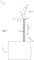
- the upper guide means 51 comprise at least one rail 511 on which the flange 22 of the containers 2 is intended to slide.
- the upper guide means 51 comprise two rails 511 spaced from one another to define between them a passage path for the containers 2.
- At least one of the two rails 511 is movably mounted on the frame 55 so as to be able to adapt the passage path of the containers 2 to necks 21 of different sizes.
- the transfer unit 5 comprises two lateral guides 52 each positioned on one side of the predetermined trajectory T, that is to say on either side of the containers 2 transferred.
- the side guides 52 are advantageously movably mounted on the frame 55 (the connection between the side guides 52 and the frame not being illustrated) so as to adapt to different widths or different diameters of containers 2.
- the side guides 52 are in particular intended to be arranged opposite the body 23 of the containers 2 to prevent the containers 2 from swinging perpendicular to the predetermined trajectory T, as illustrated by the crossed out arrow 521.
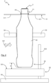
- the lower guide 53 has an upper face 531 intended to form a stop in swinging the containers 2 according to the predetermined trajectory T.
- the lower guide 53 comprises a plate 532 extending along the predetermined trajectory T.
- the plate 532 is movably mounted on the frame 55, for example by means of a lifting column 533 secured to the frame 55. This allows in particular to be able to adjust the distance between the bottom 24 of the containers 2 and the face upper 531 of the lower guide 53 to create a space E between them.
- the space E between the bottom 24 of the containers 2 and the upper face 531 of the lower guide 53 is preferably between 1 mm and 2 mm.
- the cooling means 54 comprise a plurality of air injection orifices 541 oriented so as to cool the bottom 24 of the containers 2
- the cooling means 54 of the containers 2 are integrated into the lower guide 53. More precisely, the cooling means 54 are integrated into the plate 532 of the lower guide 53.
- the plate 532 thus carries the upper face 531 of the lower guide 53. In in other words, the upper face 531 is formed by an upper surface of the plate 532.
- the cooling means 54 are formed by a cooling air pipe 542 made in a thickness of the plate 532, the cooling air pipe 542 extending along the predetermined trajectory T.
- the orifices 541 are then made in the plate 532 so as to communicate with the cooling air pipe 542 and to open onto the upper face 531 of the lower guide 53.
- a cooling air circulating in the air pipe of cooling 541 can be injected towards the bottom 24 of the containers 2.
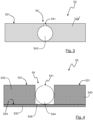
- the cooling means 54 comprise a pair of longitudinal beams 543 spaced apart from each other to form a groove 545 with the plate 532.
- the upper face 531 is then carried by the longitudinal members 543.
- the cooling air line 544 is mounted in the groove 545 and has the ports 541 to allow cooling air circulating in the cooling air line 544 can be injected towards the bottom 24 of the containers 2.
- the cooling air pipe 544 has a diameter of between 8 mm and 37 mm, and more preferably, between 25 mm and 29 mm.
- the groove 545 can be made directly by milling in the thickness of the plate 532.
- the use of longitudinal members 543 makes it possible to adjust the space E between the bottom 24 of the containers 2 even more finely. and the upper face 531. In fact, it is simply necessary to change the longitudinal members 543 to adjust the space E, by increasing or decreasing it.
- the cooling means 54 are fluidly connected to the forming unit 3 to recover the blowing air from the containers 2.
- the air extracted during the degassing phase which has a pressure generally between 20 bars and 45 bars, is generally divided into a first part which is reused for blowing another container 2, and a second part which is released into the atmosphere.
- This second part of air can then be used for cooling the bottom 24 of containers 2 in the transfer unit 5.
- the air extracted from the forming unit 3 is then routed to the cooling air pipe 544 or to the cooling air pipe 542 to be injected towards the bottom 24 of the containers 2.
- ad hoc air cooling means can be provided between the forming unit 3 and the transfer unit 5.
- the cooling means 54 are thus means for cooling the bottom 24 of the containers 2 to a temperature between -10°C and 5°C.
- the cooling means 54 allow cooling of the bottom 24 of the containers 2 to a temperature between -6°C and 0°C.
- the lateral guides 52 and the longitudinal members 543 could be a single piece so that the containers 2 are guided laterally by their bottom 24.
- the containers 2 are suspended by their collar 22 on the rails 511 of the upper guide means 51.
- the containers 2 then slide on the rails 511, according to the predetermined trajectory T, to reach the processing unit 4.
- the containers 2 are kept substantially horizontal thanks to the side guides 52 and the lower guide 53. In other words, the containers do not tilt back and forth or from right to left during their transfer.
- the containers 2 are therefore guided but also cooled (on their bottom 24) thanks to the cooling means 54.
- the guiding and cooling of the containers 2 are combined thanks to the transfer unit 5 according to the invention.
Landscapes
- Physics & Mathematics (AREA)
- Thermal Sciences (AREA)
- Engineering & Computer Science (AREA)
- Manufacturing & Machinery (AREA)
- Mechanical Engineering (AREA)
- Health & Medical Sciences (AREA)
- Oral & Maxillofacial Surgery (AREA)
- Blow-Moulding Or Thermoforming Of Plastics Or The Like (AREA)
- Auxiliary Devices For And Details Of Packaging Control (AREA)
- Moulds For Moulding Plastics Or The Like (AREA)
Claims (11)
- Einheit (5) zum Transferieren von Behältern (2) am Ausgang einer Einheit (3) zum Formen der Behälter (2), wobei die Behälter (2) einen Boden (24) aufweisen, der dazu bestimmt ist, eine Auflagefläche des Behälters (2) zu bilden, wobei die Transfereinheit (5) Folgendes umfasst:- obere Mittel (51) zum Führen der Behälter (2) entlang einer vorbestimmten Bahn (T);- Mittel (54) zum Kühlen des Bodens (24) der Behälter (2),dadurch gekennzeichnet, dass die Kühlmittel (54) in eine untere Führung (53) der Behälter (2) integriert sind, wobei die untere Führung (53) eine obere Seite (531) aufweist, die dazu bestimmt ist, ohne Kontakt gegenüber den Böden (24) der Behälter (2) angeordnet zu sein, wobei die obere Seite (531) einen Anschlag beim Schwingen der Behälter (2) entlang der vorbestimmten Bahn (T) bildet.
- Transfereinheit (5) nach Anspruch 1, dadurch gekennzeichnet, dass die Kühlmittel (54) eine Vielzahl von Lufteinblasöffnungen (541) umfassen, die so ausgerichtet sind, dass sie den Boden (24) der Behälter (2) kühlen.
- Transfereinheit (5) nach Anspruch 1 oder 2, dadurch gekennzeichnet, dass die untere Führung (53) mindestens eine Platte (532) umfasst, die die obere Seite (531) aufweist.
- Transfereinheit (5) nach Anspruch 2 und 3, dadurch gekennzeichnet, dass sich die Platte (532) entlang der vorbestimmten Bahn (T) erstreckt und einen Kühlluftkanal (542) beinhaltet, der sich entlang der vorbestimmten Bahn (T) erstreckt, wobei die Öffnungen (541) an einer oberen Fläche (534) der Platte (532) münden und mit dem Kühlluftkanal (542) in Verbindung stehen, um das Einblasen von Luft aus dem Kühlluftkanal (542) in Richtung des Bodens (24) der Behälter (2) zu ermöglichen.
- Transfereinheit (5) nach Anspruch 3 oder 4, dadurch gekennzeichnet, dass die Kühlmittel (54) Folgendes umfassen:- ein Paar Längsträger (543), die an einer oberen Fläche (534) der Platte (532) montiert sind, wobei die Längsträger (543) voneinander beabstandet sind, um mit der Platte (532) eine Nut (545) zu bilden, und die obere Seite (531) tragen;- mindestens eine Kühlluftleitung (544), die in der Nut (545) angeordnet ist, wobei die Kühlluftleitung (544) Öffnungen (541) aufweist, um das Einblasen von Luft aus der Kühlluftleitung (544) in Richtung der Böden (24) der Behälter (2) zu ermöglichen.
- Transfereinheit (5) nach Anspruch 5, dadurch gekennzeichnet, dass die Kühlluftleitung (544) einen Durchmesser zwischen 8 mm und 37 mm aufweist.
- Transfereinheit (5) nach einem der vorangehenden Ansprüche, dadurch gekennzeichnet, dass die Kühlmittel (54) mit einer Formeinheit (3) verbunden sind, die entlang der vorbestimmten Bahn (T) der Behälter (2) stromaufwärts der Transfereinheit (5) positioniert ist, um Behälterblasluft als Luft zum Kühlen des Bodens (24) der Behälter (2) zurückzugewinnen.
- Transfereinheit (5) nach einem der vorangehenden Ansprüche, dadurch gekennzeichnet, dass die oberen Führungsmittel (51) mindestens eine Schiene (511) umfassen, wobei die Behälter (2) einen Kragen (22) aufweisen, der dazu bestimmt ist, auf der Schiene (511) zu gleiten.
- Transfereinheit (5) nach einem der vorangehenden Ansprüche, dadurch gekennzeichnet, dass sie eine Seitenführung (52) umfasst, um die Bewegung der Behälter (2) senkrecht zu ihrer vorbestimmten Bahn (T) zu begrenzen.
- Transfereinheit (5) nach einem der vorangehenden Ansprüche, dadurch gekennzeichnet, dass die untere Führung (53) beweglich an einem Gestell (55) montiert ist, um eine Anpassung des Abstands zwischen den Kühlmitteln (54) und dem Boden (24) der Behälter (2) zu ermöglichen.
- Transfereinheit (5) nach einem der vorangehenden Ansprüche, dadurch gekennzeichnet, dass es sich bei den Kühlmitteln (54) um Mittel zum Kühlen der Böden (24) von Behältern (2) auf eine Temperatur zwischen -10 °C und 5 °C handelt.
Applications Claiming Priority (2)
| Application Number | Priority Date | Filing Date | Title |
|---|---|---|---|
| FR1858858A FR3086573B1 (fr) | 2018-09-27 | 2018-09-27 | Unite de transfert de recipients |
| PCT/FR2019/052257 WO2020065214A1 (fr) | 2018-09-27 | 2019-09-25 | Unite de transfert de recipients |
Publications (2)
| Publication Number | Publication Date |
|---|---|
| EP3856484A1 EP3856484A1 (de) | 2021-08-04 |
| EP3856484B1 true EP3856484B1 (de) | 2024-07-31 |
Family
ID=66166017
Family Applications (1)
| Application Number | Title | Priority Date | Filing Date |
|---|---|---|---|
| EP19795267.4A Active EP3856484B1 (de) | 2018-09-27 | 2019-09-25 | Containertransfereinheit |
Country Status (4)
| Country | Link |
|---|---|
| EP (1) | EP3856484B1 (de) |
| CN (1) | CN112752642B (de) |
| FR (1) | FR3086573B1 (de) |
| WO (1) | WO2020065214A1 (de) |
Families Citing this family (1)
| Publication number | Priority date | Publication date | Assignee | Title |
|---|---|---|---|---|
| WO2024156341A1 (en) * | 2023-01-24 | 2024-08-02 | Sidel Participations | A cooling machine for cooling bases of conveyed bottles |
Family Cites Families (10)
| Publication number | Priority date | Publication date | Assignee | Title |
|---|---|---|---|---|
| FR2806067A1 (fr) * | 2000-03-08 | 2001-09-14 | Netra Systems | Procede de transport d'articles entre deux rails de guidage sous l'action de jets d'air et convoyeur a air pour la mise en oeuvre de ce procede |
| FR2871093B1 (fr) * | 2004-06-08 | 2007-11-16 | Sidel Sas | Procede et installation de fabrication de recipients avec refroidissement apres formage |
| DE202007008120U1 (de) * | 2007-06-06 | 2007-08-16 | Krones Ag | Vorrichtung zum Herstellen und Kühlen von Kunststoffhohlkörpern |
| DE102008032123B4 (de) * | 2008-07-08 | 2024-05-16 | Krones Aktiengesellschaft | Vorrichtung zum Kühlen von Behältnissen mit einer Zuführeinrichtung welche ein fließfähiges Medium auf einen Bodenbereich der Behältnisse richtet sowie Verfahren zum Kühlen der Außenwandung von Behältnissen |
| FR2934517B1 (fr) | 2008-07-31 | 2013-04-26 | Sidel Participations | Procede et installation pour appliquer un fluide sur des fonds de recipients thermoplastiques, notamment pour le refroidissement des fonds chauds de recipients sortant de moulage |
| DE102008048812A1 (de) * | 2008-09-24 | 2010-04-01 | Khs Ag | Verfahren und Vorrichtung zur kombinierten Herstellung und Abfüllung von Behältern aus Kunststoff |
| JP5589272B2 (ja) * | 2008-09-29 | 2014-09-17 | 大日本印刷株式会社 | 搬送装置および無菌充填システム |
| DE102013109907A1 (de) * | 2013-09-10 | 2015-03-12 | Krones Ag | Vorrichtung zur Bodennachkühlung |
| JP6663234B2 (ja) * | 2016-01-29 | 2020-03-11 | 三菱重工業株式会社 | 保管容器の転倒防止装置および転倒防止方法 |
| EP3348377B1 (de) * | 2017-01-12 | 2019-10-09 | Sidel Participations | Behälterförder- und -kühlvorrichtung, verfahren zum betrieb solch einer behälterförder- und -kühlvorrichtung und behälterbehandlungsmaschine mit solch einer behälterförder- und -kühlvorrichtung |
-
2018
- 2018-09-27 FR FR1858858A patent/FR3086573B1/fr active Active
-
2019
- 2019-09-25 EP EP19795267.4A patent/EP3856484B1/de active Active
- 2019-09-25 CN CN201980063388.0A patent/CN112752642B/zh active Active
- 2019-09-25 WO PCT/FR2019/052257 patent/WO2020065214A1/fr not_active Ceased
Also Published As
| Publication number | Publication date |
|---|---|
| FR3086573B1 (fr) | 2021-07-23 |
| EP3856484A1 (de) | 2021-08-04 |
| WO2020065214A1 (fr) | 2020-04-02 |
| FR3086573A1 (fr) | 2020-04-03 |
| CN112752642B (zh) | 2023-08-15 |
| CN112752642A (zh) | 2021-05-04 |
Similar Documents
| Publication | Publication Date | Title |
|---|---|---|
| EP1778455B1 (de) | Verfahren und anlage zur behälterherstellung | |
| EP2686259B1 (de) | Übertragungsvorrichtung mit einem greifer | |
| WO2004065105A1 (fr) | Procede et installation de fabrication d'un recipient en matiere plastique | |
| WO1996029245A1 (fr) | Installation d'embouteillage en ligne | |
| EP0989931A1 (de) | Blasdorn für behälter aus kunststoff und vorrichtung die so einen blasdorn verwendet | |
| CA2194544C (fr) | Dispositif d'etancheite entre une ebauche de recipient en matiere plastique et une tuyere de soufflage, et machine de soufflage de recipients pourvue d'un tel dispositif | |
| EP2703146B1 (de) | Abkühlungsverfahren einer Form durch Zirkulation einer Wärmeübertragungsflüssigkeit in Kontakt mit der Außenseite der Form | |
| EP3856484B1 (de) | Containertransfereinheit | |
| CA2936530A1 (fr) | Unite de moulage de preformes equipee d'un porte-noyaux mobile en rotation | |
| EP3181327B1 (de) | Giessformboden mit grossen auslassöffnungen für das formverfahren eines behälters | |
| FR2921293A1 (fr) | Procede de fabrication de recipients comprenant une operation de depressurisation intermediaire | |
| FR2950284A1 (fr) | Dispositif pour la protection thermique des cols de preformes dans un four | |
| EP2879998B1 (de) | Verfahren und vorrichtung zur herstellung von hohlen glaskörpern mit spezifischer innerer glasverteilung | |
| WO2012120119A1 (fr) | Procédé et installation de fabrication d'un article creux en verre de faible épaisseur | |
| FR2950283A1 (fr) | Four comportant des moyens embarques pour la protection thermique du col des preformes | |
| FR2828829A1 (fr) | Procede pour refroidir un corps creux a l'issue de sa fabrication par moulage a chaud et dispositif de mise en oeuvre | |
| WO2019122563A1 (fr) | Procédé d'inversion d'un fond de récipient en matière plastique, dispositif pour sa mise en œuvre et utilisation du dispositif | |
| WO2025141079A1 (fr) | Procede de fabrication de corps creux par soufflage et poste de soufflage | |
| EP4028237B1 (de) | Verfahren zur herstellung eines kunststoffbehälters mit ungekühlter kühlung eines formbauteils | |
| FR3067007A1 (fr) | Machine de fabrication de bouteilles | |
| FR3144541A1 (fr) | Dispositif de montage et/ou de démontage de nez de tournette et application à une unité de conditionnement thermique de préformes. | |
| FR3045444A1 (fr) | Procede de fabrication de recipients et accessoire de manutention pour sa mise en œuvre | |
| FR3144540A1 (fr) | Dispositif de montage et/ou de démontage de nez de tournette et application à une unité de conditionnement thermique de préformes. | |
| EP4076901A1 (de) | Vorrichtung zum erwärmen von kunststoffrohlingen, die eine vorrichtung zum schutz von vorformlingshälsen umfasst | |
| WO2025021765A1 (fr) | Contenant de liquide, procédé et dispositif de constitution d'un tel contenant |
Legal Events
| Date | Code | Title | Description |
|---|---|---|---|
| STAA | Information on the status of an ep patent application or granted ep patent |
Free format text: STATUS: UNKNOWN |
|
| STAA | Information on the status of an ep patent application or granted ep patent |
Free format text: STATUS: THE INTERNATIONAL PUBLICATION HAS BEEN MADE |
|
| PUAI | Public reference made under article 153(3) epc to a published international application that has entered the european phase |
Free format text: ORIGINAL CODE: 0009012 |
|
| STAA | Information on the status of an ep patent application or granted ep patent |
Free format text: STATUS: REQUEST FOR EXAMINATION WAS MADE |
|
| 17P | Request for examination filed |
Effective date: 20210324 |
|
| AK | Designated contracting states |
Kind code of ref document: A1 Designated state(s): AL AT BE BG CH CY CZ DE DK EE ES FI FR GB GR HR HU IE IS IT LI LT LU LV MC MK MT NL NO PL PT RO RS SE SI SK SM TR |
|
| DAV | Request for validation of the european patent (deleted) | ||
| DAX | Request for extension of the european patent (deleted) | ||
| GRAP | Despatch of communication of intention to grant a patent |
Free format text: ORIGINAL CODE: EPIDOSNIGR1 |
|
| STAA | Information on the status of an ep patent application or granted ep patent |
Free format text: STATUS: GRANT OF PATENT IS INTENDED |
|
| INTG | Intention to grant announced |
Effective date: 20240429 |
|
| GRAS | Grant fee paid |
Free format text: ORIGINAL CODE: EPIDOSNIGR3 |
|
| GRAA | (expected) grant |
Free format text: ORIGINAL CODE: 0009210 |
|
| STAA | Information on the status of an ep patent application or granted ep patent |
Free format text: STATUS: THE PATENT HAS BEEN GRANTED |
|
| AK | Designated contracting states |
Kind code of ref document: B1 Designated state(s): AL AT BE BG CH CY CZ DE DK EE ES FI FR GB GR HR HU IE IS IT LI LT LU LV MC MK MT NL NO PL PT RO RS SE SI SK SM TR |
|
| REG | Reference to a national code |
Ref country code: CH Ref legal event code: EP Ref country code: GB Ref legal event code: FG4D Free format text: NOT ENGLISH |
|
| P01 | Opt-out of the competence of the unified patent court (upc) registered |
Free format text: CASE NUMBER: APP_40546/2024 Effective date: 20240709 |
|
| REG | Reference to a national code |
Ref country code: DE Ref legal event code: R096 Ref document number: 602019056185 Country of ref document: DE |
|
| REG | Reference to a national code |
Ref country code: IE Ref legal event code: FG4D Free format text: LANGUAGE OF EP DOCUMENT: FRENCH |
|
| REG | Reference to a national code |
Ref country code: LT Ref legal event code: MG9D |
|
| REG | Reference to a national code |
Ref country code: NL Ref legal event code: MP Effective date: 20240731 |
|
| PG25 | Lapsed in a contracting state [announced via postgrant information from national office to epo] |
Ref country code: PT Free format text: LAPSE BECAUSE OF FAILURE TO SUBMIT A TRANSLATION OF THE DESCRIPTION OR TO PAY THE FEE WITHIN THE PRESCRIBED TIME-LIMIT Effective date: 20241202 |
|
| REG | Reference to a national code |
Ref country code: AT Ref legal event code: MK05 Ref document number: 1708089 Country of ref document: AT Kind code of ref document: T Effective date: 20240731 |
|
| PG25 | Lapsed in a contracting state [announced via postgrant information from national office to epo] |
Ref country code: PT Free format text: LAPSE BECAUSE OF FAILURE TO SUBMIT A TRANSLATION OF THE DESCRIPTION OR TO PAY THE FEE WITHIN THE PRESCRIBED TIME-LIMIT Effective date: 20241202 |
|
| PG25 | Lapsed in a contracting state [announced via postgrant information from national office to epo] |
Ref country code: NO Free format text: LAPSE BECAUSE OF FAILURE TO SUBMIT A TRANSLATION OF THE DESCRIPTION OR TO PAY THE FEE WITHIN THE PRESCRIBED TIME-LIMIT Effective date: 20241031 |
|
| PG25 | Lapsed in a contracting state [announced via postgrant information from national office to epo] |
Ref country code: FI Free format text: LAPSE BECAUSE OF FAILURE TO SUBMIT A TRANSLATION OF THE DESCRIPTION OR TO PAY THE FEE WITHIN THE PRESCRIBED TIME-LIMIT Effective date: 20240731 Ref country code: NL Free format text: LAPSE BECAUSE OF FAILURE TO SUBMIT A TRANSLATION OF THE DESCRIPTION OR TO PAY THE FEE WITHIN THE PRESCRIBED TIME-LIMIT Effective date: 20240731 Ref country code: GR Free format text: LAPSE BECAUSE OF FAILURE TO SUBMIT A TRANSLATION OF THE DESCRIPTION OR TO PAY THE FEE WITHIN THE PRESCRIBED TIME-LIMIT Effective date: 20241101 Ref country code: PL Free format text: LAPSE BECAUSE OF FAILURE TO SUBMIT A TRANSLATION OF THE DESCRIPTION OR TO PAY THE FEE WITHIN THE PRESCRIBED TIME-LIMIT Effective date: 20240731 |
|
| PG25 | Lapsed in a contracting state [announced via postgrant information from national office to epo] |
Ref country code: BG Free format text: LAPSE BECAUSE OF FAILURE TO SUBMIT A TRANSLATION OF THE DESCRIPTION OR TO PAY THE FEE WITHIN THE PRESCRIBED TIME-LIMIT Effective date: 20240731 |
|
| PG25 | Lapsed in a contracting state [announced via postgrant information from national office to epo] |
Ref country code: LV Free format text: LAPSE BECAUSE OF FAILURE TO SUBMIT A TRANSLATION OF THE DESCRIPTION OR TO PAY THE FEE WITHIN THE PRESCRIBED TIME-LIMIT Effective date: 20240731 |
|
| PG25 | Lapsed in a contracting state [announced via postgrant information from national office to epo] |
Ref country code: AT Free format text: LAPSE BECAUSE OF FAILURE TO SUBMIT A TRANSLATION OF THE DESCRIPTION OR TO PAY THE FEE WITHIN THE PRESCRIBED TIME-LIMIT Effective date: 20240731 Ref country code: IS Free format text: LAPSE BECAUSE OF FAILURE TO SUBMIT A TRANSLATION OF THE DESCRIPTION OR TO PAY THE FEE WITHIN THE PRESCRIBED TIME-LIMIT Effective date: 20241130 |
|
| PG25 | Lapsed in a contracting state [announced via postgrant information from national office to epo] |
Ref country code: HR Free format text: LAPSE BECAUSE OF FAILURE TO SUBMIT A TRANSLATION OF THE DESCRIPTION OR TO PAY THE FEE WITHIN THE PRESCRIBED TIME-LIMIT Effective date: 20240731 |
|
| PG25 | Lapsed in a contracting state [announced via postgrant information from national office to epo] |
Ref country code: ES Free format text: LAPSE BECAUSE OF FAILURE TO SUBMIT A TRANSLATION OF THE DESCRIPTION OR TO PAY THE FEE WITHIN THE PRESCRIBED TIME-LIMIT Effective date: 20240731 Ref country code: RS Free format text: LAPSE BECAUSE OF FAILURE TO SUBMIT A TRANSLATION OF THE DESCRIPTION OR TO PAY THE FEE WITHIN THE PRESCRIBED TIME-LIMIT Effective date: 20241031 |
|
| PG25 | Lapsed in a contracting state [announced via postgrant information from national office to epo] |
Ref country code: RS Free format text: LAPSE BECAUSE OF FAILURE TO SUBMIT A TRANSLATION OF THE DESCRIPTION OR TO PAY THE FEE WITHIN THE PRESCRIBED TIME-LIMIT Effective date: 20241031 Ref country code: PL Free format text: LAPSE BECAUSE OF FAILURE TO SUBMIT A TRANSLATION OF THE DESCRIPTION OR TO PAY THE FEE WITHIN THE PRESCRIBED TIME-LIMIT Effective date: 20240731 Ref country code: NO Free format text: LAPSE BECAUSE OF FAILURE TO SUBMIT A TRANSLATION OF THE DESCRIPTION OR TO PAY THE FEE WITHIN THE PRESCRIBED TIME-LIMIT Effective date: 20241031 Ref country code: NL Free format text: LAPSE BECAUSE OF FAILURE TO SUBMIT A TRANSLATION OF THE DESCRIPTION OR TO PAY THE FEE WITHIN THE PRESCRIBED TIME-LIMIT Effective date: 20240731 Ref country code: LV Free format text: LAPSE BECAUSE OF FAILURE TO SUBMIT A TRANSLATION OF THE DESCRIPTION OR TO PAY THE FEE WITHIN THE PRESCRIBED TIME-LIMIT Effective date: 20240731 Ref country code: IS Free format text: LAPSE BECAUSE OF FAILURE TO SUBMIT A TRANSLATION OF THE DESCRIPTION OR TO PAY THE FEE WITHIN THE PRESCRIBED TIME-LIMIT Effective date: 20241130 Ref country code: HR Free format text: LAPSE BECAUSE OF FAILURE TO SUBMIT A TRANSLATION OF THE DESCRIPTION OR TO PAY THE FEE WITHIN THE PRESCRIBED TIME-LIMIT Effective date: 20240731 Ref country code: GR Free format text: LAPSE BECAUSE OF FAILURE TO SUBMIT A TRANSLATION OF THE DESCRIPTION OR TO PAY THE FEE WITHIN THE PRESCRIBED TIME-LIMIT Effective date: 20241101 Ref country code: FI Free format text: LAPSE BECAUSE OF FAILURE TO SUBMIT A TRANSLATION OF THE DESCRIPTION OR TO PAY THE FEE WITHIN THE PRESCRIBED TIME-LIMIT Effective date: 20240731 Ref country code: ES Free format text: LAPSE BECAUSE OF FAILURE TO SUBMIT A TRANSLATION OF THE DESCRIPTION OR TO PAY THE FEE WITHIN THE PRESCRIBED TIME-LIMIT Effective date: 20240731 Ref country code: BG Free format text: LAPSE BECAUSE OF FAILURE TO SUBMIT A TRANSLATION OF THE DESCRIPTION OR TO PAY THE FEE WITHIN THE PRESCRIBED TIME-LIMIT Effective date: 20240731 Ref country code: AT Free format text: LAPSE BECAUSE OF FAILURE TO SUBMIT A TRANSLATION OF THE DESCRIPTION OR TO PAY THE FEE WITHIN THE PRESCRIBED TIME-LIMIT Effective date: 20240731 |
|
| PG25 | Lapsed in a contracting state [announced via postgrant information from national office to epo] |
Ref country code: SM Free format text: LAPSE BECAUSE OF FAILURE TO SUBMIT A TRANSLATION OF THE DESCRIPTION OR TO PAY THE FEE WITHIN THE PRESCRIBED TIME-LIMIT Effective date: 20240731 Ref country code: RO Free format text: LAPSE BECAUSE OF FAILURE TO SUBMIT A TRANSLATION OF THE DESCRIPTION OR TO PAY THE FEE WITHIN THE PRESCRIBED TIME-LIMIT Effective date: 20240731 Ref country code: DK Free format text: LAPSE BECAUSE OF FAILURE TO SUBMIT A TRANSLATION OF THE DESCRIPTION OR TO PAY THE FEE WITHIN THE PRESCRIBED TIME-LIMIT Effective date: 20240731 |
|
| PG25 | Lapsed in a contracting state [announced via postgrant information from national office to epo] |
Ref country code: MC Free format text: LAPSE BECAUSE OF FAILURE TO SUBMIT A TRANSLATION OF THE DESCRIPTION OR TO PAY THE FEE WITHIN THE PRESCRIBED TIME-LIMIT Effective date: 20240731 Ref country code: EE Free format text: LAPSE BECAUSE OF FAILURE TO SUBMIT A TRANSLATION OF THE DESCRIPTION OR TO PAY THE FEE WITHIN THE PRESCRIBED TIME-LIMIT Effective date: 20240731 |
|
| PG25 | Lapsed in a contracting state [announced via postgrant information from national office to epo] |
Ref country code: CZ Free format text: LAPSE BECAUSE OF FAILURE TO SUBMIT A TRANSLATION OF THE DESCRIPTION OR TO PAY THE FEE WITHIN THE PRESCRIBED TIME-LIMIT Effective date: 20240731 |
|
| PG25 | Lapsed in a contracting state [announced via postgrant information from national office to epo] |
Ref country code: SK Free format text: LAPSE BECAUSE OF FAILURE TO SUBMIT A TRANSLATION OF THE DESCRIPTION OR TO PAY THE FEE WITHIN THE PRESCRIBED TIME-LIMIT Effective date: 20240731 |
|
| REG | Reference to a national code |
Ref country code: CH Ref legal event code: PL |
|
| REG | Reference to a national code |
Ref country code: DE Ref legal event code: R097 Ref document number: 602019056185 Country of ref document: DE |
|
| PG25 | Lapsed in a contracting state [announced via postgrant information from national office to epo] |
Ref country code: LU Free format text: LAPSE BECAUSE OF NON-PAYMENT OF DUE FEES Effective date: 20240925 |
|
| PLBE | No opposition filed within time limit |
Free format text: ORIGINAL CODE: 0009261 |
|
| STAA | Information on the status of an ep patent application or granted ep patent |
Free format text: STATUS: NO OPPOSITION FILED WITHIN TIME LIMIT |
|
| GBPC | Gb: european patent ceased through non-payment of renewal fee |
Effective date: 20241031 |
|
| 26N | No opposition filed |
Effective date: 20250501 |
|
| PG25 | Lapsed in a contracting state [announced via postgrant information from national office to epo] |
Ref country code: GB Free format text: LAPSE BECAUSE OF NON-PAYMENT OF DUE FEES Effective date: 20241031 |
|
| REG | Reference to a national code |
Ref country code: BE Ref legal event code: MM Effective date: 20240930 |
|
| PG25 | Lapsed in a contracting state [announced via postgrant information from national office to epo] |
Ref country code: BE Free format text: LAPSE BECAUSE OF NON-PAYMENT OF DUE FEES Effective date: 20240930 Ref country code: IT Free format text: LAPSE BECAUSE OF NON-PAYMENT OF DUE FEES Effective date: 20240925 |
|
| PG25 | Lapsed in a contracting state [announced via postgrant information from national office to epo] |
Ref country code: CH Free format text: LAPSE BECAUSE OF NON-PAYMENT OF DUE FEES Effective date: 20240930 |
|
| PG25 | Lapsed in a contracting state [announced via postgrant information from national office to epo] |
Ref country code: IE Free format text: LAPSE BECAUSE OF NON-PAYMENT OF DUE FEES Effective date: 20240925 |
|
| PG25 | Lapsed in a contracting state [announced via postgrant information from national office to epo] |
Ref country code: SE Free format text: LAPSE BECAUSE OF FAILURE TO SUBMIT A TRANSLATION OF THE DESCRIPTION OR TO PAY THE FEE WITHIN THE PRESCRIBED TIME-LIMIT Effective date: 20240731 |
|
| PGFP | Annual fee paid to national office [announced via postgrant information from national office to epo] |
Ref country code: DE Payment date: 20250820 Year of fee payment: 7 |
|
| PGFP | Annual fee paid to national office [announced via postgrant information from national office to epo] |
Ref country code: FR Payment date: 20250820 Year of fee payment: 7 |
|
| PG25 | Lapsed in a contracting state [announced via postgrant information from national office to epo] |
Ref country code: CY Free format text: LAPSE BECAUSE OF FAILURE TO SUBMIT A TRANSLATION OF THE DESCRIPTION OR TO PAY THE FEE WITHIN THE PRESCRIBED TIME-LIMIT; INVALID AB INITIO Effective date: 20190925 |
|
| PG25 | Lapsed in a contracting state [announced via postgrant information from national office to epo] |
Ref country code: HU Free format text: LAPSE BECAUSE OF FAILURE TO SUBMIT A TRANSLATION OF THE DESCRIPTION OR TO PAY THE FEE WITHIN THE PRESCRIBED TIME-LIMIT; INVALID AB INITIO Effective date: 20190925 |