EP3856059B1 - Fixationssystem für knochen - Google Patents
Fixationssystem für knochen Download PDFInfo
- Publication number
- EP3856059B1 EP3856059B1 EP19779354.0A EP19779354A EP3856059B1 EP 3856059 B1 EP3856059 B1 EP 3856059B1 EP 19779354 A EP19779354 A EP 19779354A EP 3856059 B1 EP3856059 B1 EP 3856059B1
- Authority
- EP
- European Patent Office
- Prior art keywords
- screw
- bone
- fixation system
- hole
- plate
- Prior art date
- Legal status (The legal status is an assumption and is not a legal conclusion. Google has not performed a legal analysis and makes no representation as to the accuracy of the status listed.)
- Active
Links
Images

Classifications
-
- A—HUMAN NECESSITIES
- A61—MEDICAL OR VETERINARY SCIENCE; HYGIENE
- A61B—DIAGNOSIS; SURGERY; IDENTIFICATION
- A61B17/00—Surgical instruments, devices or methods
- A61B17/56—Surgical instruments or methods for treatment of bones or joints; Devices specially adapted therefor
- A61B17/58—Surgical instruments or methods for treatment of bones or joints; Devices specially adapted therefor for osteosynthesis, e.g. bone plates, screws or setting implements
- A61B17/68—Internal fixation devices, including fasteners and spinal fixators, even if a part thereof projects from the skin
- A61B17/80—Cortical plates, i.e. bone plates; Instruments for holding or positioning cortical plates, or for compressing bones attached to cortical plates
- A61B17/8004—Cortical plates, i.e. bone plates; Instruments for holding or positioning cortical plates, or for compressing bones attached to cortical plates with means for distracting or compressing the bone or bones
- A61B17/8014—Cortical plates, i.e. bone plates; Instruments for holding or positioning cortical plates, or for compressing bones attached to cortical plates with means for distracting or compressing the bone or bones the extension or compression force being caused by interaction of the plate hole and the screws
-
- A—HUMAN NECESSITIES
- A61—MEDICAL OR VETERINARY SCIENCE; HYGIENE
- A61B—DIAGNOSIS; SURGERY; IDENTIFICATION
- A61B17/00—Surgical instruments, devices or methods
- A61B17/56—Surgical instruments or methods for treatment of bones or joints; Devices specially adapted therefor
- A61B17/58—Surgical instruments or methods for treatment of bones or joints; Devices specially adapted therefor for osteosynthesis, e.g. bone plates, screws or setting implements
- A61B17/68—Internal fixation devices, including fasteners and spinal fixators, even if a part thereof projects from the skin
- A61B17/80—Cortical plates, i.e. bone plates; Instruments for holding or positioning cortical plates, or for compressing bones attached to cortical plates
- A61B17/8052—Cortical plates, i.e. bone plates; Instruments for holding or positioning cortical plates, or for compressing bones attached to cortical plates immobilised relative to screws by interlocking form of the heads and plate holes, e.g. conical or threaded
- A61B17/8057—Cortical plates, i.e. bone plates; Instruments for holding or positioning cortical plates, or for compressing bones attached to cortical plates immobilised relative to screws by interlocking form of the heads and plate holes, e.g. conical or threaded the interlocking form comprising a thread
-
- A—HUMAN NECESSITIES
- A61—MEDICAL OR VETERINARY SCIENCE; HYGIENE
- A61B—DIAGNOSIS; SURGERY; IDENTIFICATION
- A61B17/00—Surgical instruments, devices or methods
- A61B17/56—Surgical instruments or methods for treatment of bones or joints; Devices specially adapted therefor
- A61B17/58—Surgical instruments or methods for treatment of bones or joints; Devices specially adapted therefor for osteosynthesis, e.g. bone plates, screws or setting implements
- A61B17/68—Internal fixation devices, including fasteners and spinal fixators, even if a part thereof projects from the skin
- A61B17/84—Fasteners therefor or fasteners being internal fixation devices
- A61B17/86—Pins or screws or threaded wires; nuts therefor
- A61B17/8605—Heads, i.e. proximal ends projecting from bone
Definitions
- the invention relates to a fixation system for a bone according to the preamble of claim 1.
- bone plates and bone screws are used for the surgical treatment of bone injuries, especially complicated bone fractures. Fracture compression is particularly important here: the use of special bone plates not only enables the fixation of the bone fragments, but also the displacement of the bone fragments relative to one another.
- Bone plates that enable fracture compression are well known and are used routinely.
- suitable bone plates can have oval through holes into which bone screws can be inserted eccentrically. When screwed in, the bone screw gradually centers itself in the through hole. Since the screw is already connected to the bone, the bone shifts relative to the bone plate. Two bone fragments can be shifted towards each other in this way and a fracture can be compressed.
- fixation systems for bones are known from the state of the art that, in addition to fracture compression, enable an angle-stable connection between the bone screw and the bone plate.
- An angle-stable connection usually refers to a force-fit or material-fit connection between the bone screw and the bone plate and is also referred to as "locking".
- the DE 10 2010 025 001 A1 and the WO 2011/160846 A1 describe bone plates that have through holes with a circumferential radial rib.
- This rib enables clamping with the head thread of a bone screw and thus an angle-stable connection.
- the described through holes have a truncated cone shape that tapers towards the underside of the plate and which, when using a bone screw with a conical seat, enables the bone plate to be moved relative to the bone.
- bone plates When used with bone screws with a head thread and a conical seat, bone plates enable fracture compression and angular stability, but the bone screw must be positioned parallel to the hole axis.
- Bone fixation systems that enable fracture compression and in which the bone screw can be connected to the bone plate at an oblique angle to the hole axis are also known from the state of the art. In this case, one also speaks of a polyaxial or multidirectional connection between the bone screw and the bone plate.
- the EP 2 364 658 A1 discloses, for example, bone plates with through holes that simultaneously allow a relative displacement of the bone plate and bone and a polyaxial connection between the bone screw and the bone plate.
- bone screws with a spherical seat surface without a head thread must be used with the bone plates described.
- the bone plates described can also be used with screws with a conical seat surface and head thread. In this case, an angle-stable connection is possible, but not polyaxiality.
- fixation systems for bones that simultaneously enable angle-stable and polyaxial connections between bone screws and bone plates.
- DE 43 43 117 A1 such a fixation system.
- the angular stability is achieved by the material being deformed when the bone screw is screwed in and a threaded connection being formed between a preformed thread on the bone screw or bone plate and the other component.
- the fixation system described cannot be used for fracture compression.
- fixation system for bones that enables fracture compression and at the same time allows an angle-stable polyaxial connection between the bone screw and the bone plate would be advantageous.
- Some fixation systems known from the state of the art attempt to solve this problem, but these have known fixation systems have considerable disadvantages.
- the WO 00/66012 A1 attempts to solve this problem by using special bone screws that have a short additional locking thread on the screw neck between a screw head with a smooth seat and the usual screw thread on the screw shaft.
- the locking thread can screw into an engagement contour in the bone plate and fix the bone screw at a stable angle.
- the internal engagement contour should allow a slight angular offset of the screwed-in screw to the hole axis.
- the screw In order to achieve fracture compression, the screw should be inserted eccentrically into a long hole.
- a significant disadvantage of the bone plates and bone screws described is that polyaxiality is only possible to a very limited extent, i.e. only a slight angular offset of the inserted bone screw is possible.
- the DE 198 58 889 A1 attempts to solve the problem by using similar bone screws.
- the bone screws described also have a screw head with a smooth seat and an additional locking thread between the screw head and the screw shaft.
- One of the described versions of the bone plates has elongated through holes that are intended to enable fracture compression. It should be possible to insert the bone screw at an oblique angle.
- a deformable projection in the through hole in conjunction with the locking thread of the bone screw should enable an angle-stable connection.
- a significant disadvantage of the fixation system described is that the angular stability can only be achieved to a very low degree. When screwed in, the bone screw is in contact with the wall of the elongated through hole over a maximum of 180° of its circumference. Since it cannot screw itself to the deformable projection over its entire circumference, high angular stability cannot be achieved.
- the object of the present invention is to alleviate or eliminate at least some of the disadvantages of the prior art.
- the invention has the particular aim of providing a fixation system for bones that enables displacement of bones relative to the bone plate and at the same time enables an angle-stable, polyaxial connection between the bone plate and the bone screw.
- the through hole has a guide section which tapers from the screw entry opening in the direction of the screw exit opening, so that the essentially spherical seat surface of the screw head slides along a guide surface of the guide section and is guided into the blocking section when the bone screw is screwed into the bone, while the bone plate is displaced.
- the invention thus simultaneously enables the use of the bone screw at different oblique angles to the hole axis (polyaxiality), an angle-stable connection between the bone plate and the bone screw at these oblique angles and a displacement of the bone plate relative to the bone when screwing in the bone screw.
- the spherical seat surface and the head thread of the bone screw form a unit.
- the bone screw has no additional seat surface above the head thread.
- the head thread of the bone screw is part of the spherical seat surface of the screw head.
- the guide surface of the through hole enables the bone plate to be displaced relative to the bone when the bone screw is screwed in.
- the displacement takes place in a direction transverse to the hole axis, i.e. in a direction in the plane of the plate. In this way, for example, the distance between two bone fragments can be reduced and fracture compression can be achieved. It is particularly advantageous if the guide surface has essentially smooth walls.
- the locking section represents a circle when viewed in cross-section.
- the locking section is essentially cylindrical. This makes it possible for the screw head, when locked, to rest against the walls of the through hole over the entire circumference of the locking section when viewed in cross-section. In other words, the screw head can be fixed from all sides when viewed in the plane of the plate. This enables the bone screw to be locked particularly stably.
- the locking section is essentially conical.
- the cone angle can be between 1° and 25°, preferably between 4° and 20°, even more preferably between 8° and 20°, most preferably between 12° and 16°. This improves the biting behavior of the screw head.
- the deformable projection extends over the entire circumference of the locking section when viewed in cross-section. This has the advantage that the screw head can be screwed over the entire circumference of the locking section when viewed in cross-section, thereby achieving a particularly stable locking.
- the deformable projection is part of a deformable thread.
- the thread can preferably have at least one full turn, even more preferably at least two full turns.
- the screw head can thus screw particularly securely into the locking section.
- the guide section has an input surface that is parallel to the hole axis, i.e. extends perpendicular to the plate plane.
- the guide section has an inclined guide surface leading to the locking section, which preferably adjoins the entry surface directly.
- the guide surface is preferably smooth-walled. This enables the seat surface of the screw head to slide particularly easily.
- the guide surface can also be curved.
- the angle of the guide surface to the plate plane in longitudinal section is between 10° and 80°, preferably between 20° and 70°, even more preferably between 30° and 60°, even more preferably between 40° and 50°.
- the guide section has an input surface parallel to the hole axis and an inclined guide surface leading to the blocking section.
- the guide surface extends to the screw exit opening on the top of the plate.
- the guide section does not have a stepped entry surface.
- the screw head is completely accommodated in the blocking section in the blocked state.
- Completely accommodated in this context means that, viewed in longitudinal section, no part of the screw head protrudes beyond the blocking section.
- the complete accommodation of the screw head in the blocking section has the advantage that the screw head can be fixed particularly stably.
- an elongated hole is provided as the screw entry opening.
- the width of the elongated hole corresponds essentially to the diameter of the screw exit opening.
- the width in this case refers to The distance between the parallel longitudinal sides of the elongated hole is preferably constant in this embodiment in the direction of the width of the elongated hole in the entire area between the screw entry opening and the screw exit opening.
- the through hole has a cylindrically shaped side wall extending between the screw entry opening and the screw exit opening.
- the screw entry opening is preferably an elongated hole and the screw exit opening is a round hole, the width of the elongated hole corresponding to the diameter of the round hole.
- the screw entry opening and the screw exit opening are preferably positioned one above the other in such a way that the circular segment that closes off the screw entry opening on one side is arranged in longitudinal section essentially parallel to the circle describing the screw exit opening.
- the cross section of the cylindrical surface is preferably an arc of a circle with a central angle of 180°.
- This embodiment has the advantage that the displacement of the bone plate relative to the bone when screwing in the bone screw is only possible in the direction of the longitudinal axis of the elongated hole.
- the direction in which the displacement is to take place can thus be specified by the placement of the through hole in the bone plate.
- a further advantage is that a cylindrically shaped side wall extending between the screw entry opening and the screw exit opening enables easy production.
- the blocking section extends along the hole axis over 1/5 to 4/5, even more preferably between 2/5 and 4/5, even more preferably between 3/5 and 4/5 of the distance between the screw entry opening and the screw exit opening (ie the longitudinal extension of the through hole). It is particularly preferred if the blocking section extends along the hole axis over a distance of at least 0.5 millimeters, even more preferably at least 1 millimeter, most preferably at least 1.5 millimeters.
- the guide section extends along the hole axis over 1/5 to 4/5, even more preferably between 2/5 and 4/5, even more preferably between 3/5 and 4/5 of the distance between the screw entry opening and the screw exit opening. It is particularly preferred if the guide section extends along the hole axis over a distance of at least 0.25 millimeters, even more preferably at least 0.5 millimeters, most preferably at least 1.0 millimeter.
- the bone screws of the fixation system according to the invention can be, for example, cancellous screws or cortical screws.
- Cancellous screws can be used in a fixation system according to the invention in an angle range of up to 70°.
- Cortical screws can be used in an angle range of up to 45°.
- all location and direction information such as “top” and “bottom”, refer to the intended use state when the bone plate rests on the bone.
- the “plate plane” is to be understood as the main plane of the bone plate in the area of the through hole.
- the following explanations refer to a design in which the "hole axis” extends perpendicular to the plate plane.
- the hole axis can also run at an angle to the plate plane, in which case the directions must be transferred accordingly.
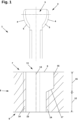
- Fig. 1 shows a fixation system 1 for a bone (not shown).
- the fixation system 1 has a bone screw 2 with a screw head 3 with an essentially spherical seat surface 4.
- a head thread 5 is also formed on the seat surface 4.
- the fixation system 1 also has a bone plate 6 for the angle-stable, polyaxial blocking of the bone screw 2.
- the bone plate 6 has a plate top 7 with a screw entry opening 8 for inserting the bone screw 2 and a plate bottom 9 with a screw exit opening 10 intended for bone contact.
- a through hole 11 extends between the screw entry opening 8 and the screw exit opening 10.
- the through hole 11 has a locking section 12 which serves to stably fix the bone screw 2 at different angles to the hole axis 13.
- the locking section 12 has at least one deformable projection 14.
- the blocking section 12 is essentially cylindrical and has a formable thread.
- the formable projection 14 is therefore part of a formable thread in this embodiment.
- the through hole 11 also has a guide section 15 which tapers from the screw entry opening 8 towards the screw exit opening 10.
- the guide section 15 has an input surface 16 parallel to the hole axis and an inclined guide surface 17 leading to the blocking section 12.
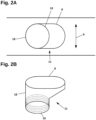
- Fig. 2A shows a schematic top view
- Fig. 2B shows a schematic perspective view of a preferred embodiment of the through hole 11.
- the screw entry opening 8 is an elongated hole
- the screw exit opening 10 is a circular hole.
- the width b of the elongated hole corresponds to the diameter of the screw exit opening 10.
- the extension of the through hole 11 in the direction of the width b of the elongated hole is constant in the entire area between the screw entry opening 8 and the screw exit opening 10.
- the through hole 11 also has a cylindrically shaped side wall 18 extending between the screw inlet opening 8 and the screw outlet opening 10, which, viewed in cross-section, describes a circular arc with a central angle of 180°.
- Fig. 3A to 3E shows the application of the Figure 1 shown bone screw 2 and bone plate 6.
- Fig. 3A to 3E show successive states when screwing in the bone screw 2.
- Fig. 3A shows the attachment of the bone screw 2.
- the bone screw 2 is attached off-center with respect to the locking section 12.
- Fig. 3B the bone screw 2 is screwed in to the point where the screw head 3 with its seat 4 rests on the guide surface 17.
- Fig. 3C shows how the bone plate 6 is displaced by the sliding of the screw head 3 along the guide surface 17.
- the bone screw 2 moves gradually from the edge of the locking section 12 to its center when screwed in. Since the bone screw 2 has already entered the bone (not shown), this causes a displacement of the bone plate 6 relative to the bone (not shown).
- Fig. 3D shows a state of the fixation system 1 in which the displacement of the bone plate 6 is completed.
- the bone screw 2 is centered in the locking section 12 but not yet locked.
- Fig 3E shows the locked state of the fixation system 1.
- the screw head 3 is completely received in the locking section 12 and the bone screw 2 is stably locked.
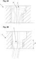
- FIG. 4A shows that in Figure 1 illustrated fixation system 1, wherein the bone screw 2 was inserted at an oblique angle to the hole axis 13.
- Fig. 4B shows the angle-stable locked state after the displacement of the bone plate 6 relative to the bone (not shown) has taken place and the screw head 3 has entered the locking section 12.
- the fixation system can be used to compress a bone fracture as follows: The bone plate is placed on a piece of bone to be fixed and screwed to the bone with a bone screw.
- the bone screw can be inserted either parallel to the hole axis or at an oblique angle. After it has been fully screwed in, the bone screw is locked at a stable angle.
- the bone plate is screwed to another piece of bone.
- the bone screw is placed eccentrically in relation to the blocking section and screwed into the bone either parallel to the hole axis or at an oblique angle. By gradually centering the bone screw in the blocking section, the piece of bone connected to the bone screw moves in the direction of the piece of bone already fixed to the bone plate. After it has been fully screwed in, the bone screw is locked at a stable angle and the fracture compression is complete.
Landscapes
- Health & Medical Sciences (AREA)
- Orthopedic Medicine & Surgery (AREA)
- Surgery (AREA)
- Life Sciences & Earth Sciences (AREA)
- Heart & Thoracic Surgery (AREA)
- Nuclear Medicine, Radiotherapy & Molecular Imaging (AREA)
- Engineering & Computer Science (AREA)
- Biomedical Technology (AREA)
- Neurology (AREA)
- Medical Informatics (AREA)
- Molecular Biology (AREA)
- Animal Behavior & Ethology (AREA)
- General Health & Medical Sciences (AREA)
- Public Health (AREA)
- Veterinary Medicine (AREA)
- Surgical Instruments (AREA)
Description
- Die Erfindung betrifft ein Fixationssystem für einen Knochen gemäß dem Oberbegriff von Anspruch 1.
- In der Plattenosteosynthese werden Knochenplatten und Knochenschrauben zur operativen Versorgung von Knochenverletzungen, insbesondere komplizierten Knochenfrakturen, eingesetzt. Besondere Bedeutung kommt dabei der Frakturkompression zu: Der Einsatz spezieller Knochenplatten ermöglicht nicht nur die Fixierung der Knochenfragmente, sondern auch das Verschieben der Knochenfragmente relativ zueinander.
- Knochenplatten, die eine Frakturkompression ermöglichen, sind allgemein bekannt und werden routinemäßig eingesetzt. Beispielsweise können geeignete Knochenplatten ovale Durchgangslöcher aufweisen in die Knochenschrauben exzentrisch eingesetzt werden können. Beim Eindrehen zentriert sich die Knochenschraube sukzessive im Durchgangsloch. Da die Schraube bereits mit dem Knochen verbunden ist, verschiebt sich dabei der Knochen relativ zur Knochenplatte. Zwei Knochenfragmente können so zueinander verschoben werden und eine Fraktur komprimiert werden.
- Aus dem Stand der Technik sind weiters Fixationssysteme für Knochen bekannt, die neben einer Frakturkompression eine winkelstabile Verbindung zwischen Knochenschraube und Knochenplatte ermöglichen. Eine winkelstabile Verbindung bezeichnet üblicherweise eine kraftschlüssige oder stoffschlüssige Verbindung zwischen Knochenschraube und Knochenplatte und wird auch als "Verblockung" bezeichnet.
- Die
DE 10 2010 025 001 A1 und dieWO 2011/160846 A1 beschreiben Knochenplatten, die Durchgangslöcher mit einer umlaufenden radialen Rippe aufweisen. Diese Rippe ermöglicht eine Verklemmung mit dem Kopfgewinde einer Knochenschraube und damit eine winkelstabile Verbindung. Zusätzlich weisen die beschriebenen Durchgangslöcher eine kegelstumpfförmige Ausbildung auf, die sich zur Plattenunterseite hin verjüngt und die bei Verwendung einer Knochenschraube mit konischer Sitzfläche eine Verschiebung der Knochenplatte relativ zum Knochen ermöglicht. Die beschriebenen Knochenplatten ermöglichen bei der Verwendung mit Knochenschrauben mit Kopfgewinde und konischer Sitzfläche also eine Frakturkompression und Winkelstabilität, die Knochenschraube muss hierfür aber parallel zur Lochachse angesetzt werden. - Aus dem Stand der Technik sind auch Fixationssysteme für Knochen bekannt, die eine Frakturkompression ermöglichen und bei denen die Knochenschraube in einem Schrägwinkel zur Lochachse mit der Knochenplatte verbunden werden kann. In diesem Fall spricht man auch von einer polyaxialen oder multidirektionalen Verbindung zwischen Knochenschraube und Knochenplatte.
- Die
EP 2 364 658 A1 offenbart z.B. Knochenplatten mit Durchgangslöchern, die gleichzeitig eine Relativverschiebung von Knochenplatte und Knochen und eine polyaxiale Verbindung zwischen Knochenschraube und Knochenplatte ermöglichen. Zu diesem Zweck müssen bei den beschriebenen Knochenplatten zwingend Knochenschrauben mit sphärischer Sitzfläche ohne Kopfgewinde eingesetzt werden. Die beschriebenen Knochenplatten können außerdem mit Schrauben mit konischer Sitzfläche und Kopfgewinde verwendet werden. In diesem Fall ist eine winkelstabile Verbindung möglich, jedoch keine Polyaxialität. - Aus dem Stand der Technik bekannt sind außerdem Fixationssysteme für Knochen, die gleichzeitig winkelstabile und polyaxiale Verbindungen von Knochenschraube und Knochenplatte ermöglichen. Beispielsweise beschreibt die
DE 43 43 117 A1 ein derartiges Fixationssystem. Die Winkelstabilität wird dadurch erreicht, dass beim Eindrehen der Knochenschraube eine Materialumformung stattfindet und eine Gewindeverbindung zwischen einem vorgeformten Gewinde an Knochenschraube oder Knochenplatte mit der jeweils anderen Komponente gebildet wird. Allerdings kann das beschriebene Fixationssystem nicht zur Frakturkompression eingesetzt werden. - Vorteilhaft wäre ein Fixationssystem für Knochen, das eine Frakturkompression ermöglicht und gleichzeitig eine winkelstabil-polyaxiale Verbindung zwischen Knochenschraube und Knochenplatte erlaubt. Einige aus dem Stand der Technik bekannte Fixationssysteme versuchen diese Aufgabe zu lösen, allerdings weisen diese bekannten Fixationssysteme erhebliche Nachteile auf.
- Die
WO 00/66012 A1 - Die
DE 198 58 889 A1 versucht die Aufgabe durch den Einsatz ähnlicher Knochenschrauben zu lösen. Die beschriebenen Knochenschrauben haben ebenfalls einen Schraubenkopf mit glatter Sitzfläche sowie ein zusätzliches Verblockungsgewinde zwischen Schraubenkopf und Schraubenschaft. Eine der beschriebenen Ausführungsformen der Knochenplatten weist längliche Durchgangslöcher auf, die eine Frakturkompression ermöglichen sollen. Dabei soll es möglich sein, die Knochenschraube in einem Schrägwinkel einzubringen. Außerdem soll ein umformbarer Vorsprung im Durchgangsloch in Zusammenwirkung mit dem Verblockungsgewinde der Knochenschraube eine winkelstabile Verbindung ermöglichen. Ein erheblicher Nachteil des beschriebenen Fixationssystem ist allerdings, dass die Winkelstabilität nur in sehr niedrigem Ausmaß gegeben sein kann. Die Knochenschraube ist im eingedrehten Zustand über höchstens 180° ihres Umfangs mit der Wand des länglichen Durchgangsloches in Kontakt. Da sie sich nicht über ihren gesamten Umfang mit dem umformbaren Vorsprung verschrauben kann, kann keine hohe Winkelstabilität erreicht werden. - Es besteht daher weiterhin ein Bedarf an einem Fixationssystem für Knochen, das eine Verschiebung von Knochen relativ zur Knochenplatte und gleichzeitig eine winkelstabil-polyaxiale Verbindung zwischen Knochenplatte und Knochenschraube ermöglicht.
- Die Aufgabe der vorliegenden Erfindung besteht darin, zumindest einzelne Nachteile des Standes der Technik zu lindern bzw. zu beseitigen. Die Erfindung setzt sich insbesondere zum Ziel, ein Fixationssystem für Knochen bereitzustellen, das eine Verschiebung von Knochen relativ zur Knochenplatte und gleichzeitig eine winkelstabil-polyaxiale Verbindung zwischen Knochenplatte und Knochenschraube ermöglicht.
- Diese Aufgabe wird durch ein Fixationssystem mit den Merkmalen von Anspruch 1 gelöst.
- Erfindungsgemäß weist das Durchgangsloch einen Führungsabschnitt auf, der sich von der Schraubeneintrittsöffnung in Richtung der Schraubenaustrittsöffnung verjüngt, sodass die im Wesentlichen sphärische Sitzfläche des Schraubenkopfes beim Eindrehen der Knochenschraube in den Knochen, unter Verschiebung der Knochenplatte, entlang einer Führungsfläche des Führungsabschnitts gleitet und in den Verblockungsabschnitt geführt wird.
- Die Erfindung ermöglicht somit gleichzeitig den Einsatz der Knochenschraube in unterschiedlichen Schrägwinkeln zur Lochachse (Polyaxialität), eine winkelstabile Verbindung zwischen Knochenplatte und Knochenschraube in diesen Schrägwinkeln und eine Verschiebung der Knochenplatte relativ zum Knochen beim Eindrehen der Knochenschraube.
- Erfindungsgemäß ist vorgesehen, dass die sphärische Sitzfläche und das Kopfgewinde der Knochenschraube eine Einheit bilden. D.h. die Knochenschraube hat keine zusätzliche Sitzfläche oberhalb des Kopfgewindes. Anders ausgedrückt, ist das Kopfgewinde der Knochenschraube Teil der sphärischen Sitzfläche des Schraubenkopfes. Das hat den Vorteil, dass eine hohe Polyaxialität gegeben ist, so dass die Knochenschraube in einem großen Winkelbereich eingesetzt werden kann. Die Knochenschraube kann daher in unterschiedlichen Schrägwinkeln zur Lochachse winkelstabil im sich vorzugsweise an der Plattenunterseite befindenden Verblockungsabschnitt des Durchgangsloches fixiert werden.
- Die Führungsfläche des erfindungsgemäßen Durchgangsloches ermöglicht eine Verschiebung der Knochenplatte relativ zum Knochen beim Eindrehen der Knochenschraube. Die Verschiebung findet dabei in eine Richtung quer zur Lochachse, d.h. in eine Richtung in der Plattenebene statt. So kann beispielsweise der Abstand zwischen zwei Knochenfragmenten verringert werden und eine Frakturkompression erreicht werden. Besonders vorteilhaft ist es, wenn die Führungsfläche im Wesentlichen glattwandig ist.
- In einer bevorzugten Ausführungsform stellt der Verblockungsabschnitt im Querschnitt gesehen einen Kreis dar. In einer besonders bevorzugten Ausführungsform ist der Verblockungsabschnitt im Wesentlichen zylindrisch. Dadurch wird ermöglicht, dass der Schraubenkopf im verblockten Zustand im Querschnitt gesehen über den gesamten Umfang des Verblockungsabschnitts an den Wänden des Durchgangsloches anliegen kann. Anders ausgedrückt kann der Schraubenkopf in der Plattenebene gesehen von allen Seiten fixiert werden. Somit ist eine besonders stabile Verblockung der Knochenschraube möglich.
- In einer weiteren bevorzugten Ausführungsform ist der Verblockungsabschnitt im Wesentlichen konisch. Der Konuswinkel kann dabei zwischen 1° und 25°, vorzugsweise zwischen 4° und 20°, noch mehr bevorzugt zwischen 8° und 20°, am meisten bevorzugt zwischen 12° und 16° betragen. Dadurch wird das Anbeißverhalten des Schraubenkopfes verbessert.
- Vorzugsweise erstreckt sich der umformbare Vorsprung im Querschnitt gesehen über den gesamten Umfang des Verblockungsabschnitts. Das hat den Vorteil, dass sich der Schraubenkopf im Querschnitt gesehen über den gesamten Umfang des Verblocksabschnitts verschrauben kann, wodurch eine besonders stabile Verblockung erreicht wird.
- Besonders bevorzugt ist es, wenn der umformbare Vorsprung Teil eines umformbaren Gewindes ist. Das Gewinde kann vorzugsweise mindestens eine volle Umdrehung, noch mehr bevorzugt mindestens zwei volle Umdrehungen aufweisen. Somit kann sich der Schraubenkopf besonders stabil im Verblockungsabschnitt verschrauben.
- In einer bevorzugten Ausführungsform der vorliegenden Erfindung weist der Führungsabschnitt eine zur Lochachse parallele, d.h. senkrecht zur Plattenebene erstreckte, Eingangsfläche auf.
- Bevorzugt ist es außerdem, wenn der Führungsabschnitt eine schräge, zum Verblockungsabschnitt führende Führungsfläche aufweist, welche vorzugsweise unmittelbar an die Eingangsfläche anschließt. Das ermöglicht ein einfaches Gleiten der Sitzfläche des Schraubenkopfes entlang der Führungsfläche beim Eindrehen der Knochenschraube. Die Führungsfläche ist vorzugsweise glattwandig. Damit wird ein besonders einfaches Gleiten der Sitzfläche des Schraubenkopfes ermöglicht. Die Führungsfläche kann alternativ auch gekrümmt sein. In einer bevorzugten Ausführungsform beträgt der Winkel der Führungsfläche zur Plattenebene im Längsschnitt (parallel zur Lochachse) gesehen zwischen 10° und 80°, vorzugsweise zwischen 20° und 70°, noch mehr bevorzugt zwischen 30° und 60°, noch mehr bevorzugt zwischen 40° und 50°.
- Besonders bevorzugt ist es, wenn der Führungsabschnitt eine zur Lochachse parallele Eingangsfläche und eine schräge, zum Verblockungsabschnitt führende Führungsfläche aufweist.
- In einer weiteren besonders bevorzugten Ausführungsform erstreckt sich die Führungsfläche bis zur Schraubenaustrittsöffnung an der Plattenoberseite. In dieser Ausführungsform weist der Führungsabschnitt keine abgesetzte Eingangsfläche auf.
- In einer besonders bevorzugten Ausführungsform der vorliegenden Erfindung ist der Schraubenkopf im verblockten Zustand vollständig in dem Verblockungsabschnitt aufgenommen. Vollständig aufgenommen bedeutet in diesem Zusammenhang, dass im Längsschnitt gesehen, kein Teil des Schraubenkopfes über den Verblockungsabschnitt hinausragt. Die vollständige Aufnahme des Schraubenkopfes im Verblockungsabschnitt hat den Vorteil, dass der Schraubenkopf besonders stabil fixiert werden kann.
- In einer besonders bevorzugten Ausführungsform ist als Schraubeneintrittsöffnung ein Langloch vorgesehen. Vorzugsweise entspricht die Breite des Langloches im Wesentlichen dem Durchmesser der Schraubenaustrittsöffnung. Die Breite bezeichnet in diesem Zusammenhang dem Abstand der parallel zueinander verlaufenden Längsseiten des Langloches. Vorzugsweise ist in dieser Ausführungsform die Ausdehnung des Durchgangsloches in Richtung der Breite des Langloches im gesamten Bereich zwischen Schraubeneintrittsöffnung und Schraubenaustrittsöffnung im Wesentlichen konstant. Das hat den Vorteil, dass die Verschiebung der Knochenplatte relativ zum Knochen beim Eindrehen der Knochenschraube nur in der Längsachse des Langloches möglich ist. Somit kann die Achse, in der die Verschiebung stattfinden soll, durch die Platzierung des Durchgangsloches in der Knochenplatte vorgegeben werden.
- In einer weiteren bevorzugten Ausführungsform weist das Durchgangsloch eine sich zwischen der Schraubeneintrittsöffnung und der Schraubenaustrittsöffnung erstreckende zylindrisch geformte Seitenwand auf. Vorzugsweise ist in dieser Ausführungsform die Schraubeneintrittsöffnung ein Langloch und die Schraubenaustrittsöffnung ein Rundloch, wobei die Breite des Langloches dem Durchmesser des Rundloches entspricht. Vorzugsweise sind in dieser Ausführungsform die Schraubeneintrittsöffnung und die Schraubenaustrittsöffnung so übereinander positioniert, dass das die Schraubeneintrittsöffnung auf einer Seite abschließende Kreissegment im Längsschnitt gesehen im Wesentlichen parallel zu dem die Schraubenaustrittsöffnung beschreibenden Kreis angeordnet ist. Vorzugsweise ist der Querschnitt der zylindrischen Fläche ein Kreisbogen mit einem Mittelpunktswinkel von 180°. Diese Ausführungsform hat den Vorteil, dass die Verschiebung der Knochenplatte relativ zum Knochen beim Eindrehen der Knochenschraube nur in Richtung der Längsachse des Langloches möglich ist. Somit kann die Richtung, in der die Verschiebung stattfinden soll, durch die Platzierung des Durchgangsloches in der Knochenplatte vorgegeben werden. Ein weiterer Vorteil ist, dass eine sich zwischen der Schraubeneintrittsöffnung und der Schraubenaustrittsöffnung erstreckende zylindrisch geformte Seitenwand eine einfache Herstellung ermöglicht.
- Vorzugsweise erstreckt sich der Verblockungsabschnitt entlang der Lochachse über 1/5 bis 4/5, noch mehr bevorzugt zwischen 2/5 und 4/5, noch mehr bevorzugt zwischen 3/5 und 4/5 der Distanz zwischen Schraubeneintrittsöffnung und der Schraubenaustrittsöffnung (d.h. der Längserstreckung des Durchgangsloches). Besonders bevorzugt ist es, wenn sich der Verblockungsabschnitt entlang der Lochachse über eine Distanz von mindestens 0,5 Millimeter, noch mehr bevorzugt mindestens 1 Millimeter, am meisten bevorzugt mindestens 1,5 Millimeter erstreckt.
- Vorzugsweise erstreckt sich der Führungsabschnitt entlang der Lochachse über 1/5 bis 4/5, noch mehr bevorzugt zwischen 2/5 und 4/5, noch mehr bevorzugt zwischen 3/5 und 4/5 der Distanz zwischen Schraubeneintrittsöffnung und der Schraubenaustrittsöffnung. Besonders bevorzugt ist es, wenn sich der Führungsabschnitt entlang der Lochachse über eine Distanz von mindestens 0,25 Millimeter, noch mehr bevorzugt mindestens 0,5 Millimeter, am meisten bevorzugt mindestens 1,0 Millimeter erstreckt.
- Die Knochenschrauben des erfindungsgemäßen Fixationssystems können z.B. Spongiosaschrauben oder Kortikalisschrauben sein. Spongiosaschrauben können in einem erfindungsgemäßen Fixationssystem in einem Winkelbereich bis zu 70° eingesetzt werden. Kortikalisschrauben können in einem Winkelbereich bis zu 45° eingesetzt werden.
- Im Folgenden wird die Erfindung anhand von bevorzugten, nicht einschränkenden Ausführungsformen unter Bezugnahme auf die Zeichnungen näher erläutert. Es zeigen:
- Figur 1
- ein erfindungsgemäßes Fixationssystem mit einer Knochenschraube und einer Knochenplatte vor der Verbindung miteinander;
- Figur 2A
- die Knochenplatte aus
Fig. 1 in Draufsicht; - Fig. 2B
- das Durchgangsloch der Knochenplatte in einer schematischen perspektivischen Darstellung;
- Figur 3A bis 3E
- das Fixationssystem gemäß
Fig. 1 in verschiedenen Stellungen beim Eindrehen der Knochenschraube senkrecht zur Plattenebene der Knochenplatte; und - Figur 4A, 4B
- jeweils das Fixationssystem gemäß
Fig. 1 bis Fig. 3 in zwei Stellungen beim Eindrehen der Knochenschraube in einem Winkel zur Plattenebene der Knochenplatte. - Für die Zwecke dieser Offenbarung beziehen sich sämtliche Orts- und Richtungsangaben, wie "oben" und "unten" auf den bestimmungsgemäßen Gebrauchszustand, wenn die Knochenplatte auf dem Knochen aufliegt. Als "Plattenebene" ist die Hauptebene der Knochenplatte im Bereich des Durchgangsloches zu verstehen. Die folgenden Erläuterungen beziehen sich auf eine Ausführung, bei welcher die "Lochachse" senkrecht zur Plattenebene erstreckt ist. Die Lochachse kann jedoch auch schräg zur Plattenebene verlaufen, wobei die Richtungen dann entsprechend zu übertragen sind.
-
Fig. 1 zeigt ein Fixationssystem 1 für einen Knochen (nicht dargestellt). Das Fixationssystem 1 weist zum einen eine Knochenschraube 2 mit einem Schraubenkopf 3 mit einer im Wesentlichen sphärischen Sitzfläche 4 auf. An der Sitzfläche 4 ist zugleich ein Kopfgewinde 5 ausgebildet. - Das Fixationssystem 1 weist außerdem eine Knochenplatte 6 zur winkelstabil-polyaxialen Verblockung der Knochenschraube 2 auf. Die Knochenplatte 6 hat eine Plattenoberseite 7 mit einer Schraubeneintrittsöffnung 8 zum Einführen der Knochenschraube 2 und eine für den Knochenkontakt vorgesehene Plattenunterseite 9 mit einer Schraubenaustrittsöffnung 10. Zwischen der Schraubeneintrittsöffnung 8 und der Schraubenaustrittsöffnung 10 erstreckt sich ein Durchgangsloch 11.
- Das Durchgangsloch 11 weist einen Verblockungsabschnitt 12 auf, der dazu dient, die Knochenschraube 2 in verschiedenen Winkeln zur Lochachse 13 stabil zu fixieren. Zu diesem Zweck weist der Verblockungsabschnitt 12 mindestens einen umformbaren Vorsprung 14 auf. Bei der in
Fig. 1 dargestellten Ausführungsform ist der Verblockungsabschnitt 12 im Wesentlichen zylindrisch und weist ein umformbares Gewinde auf. Der umformbare Vorsprung 14 ist in dieser Ausfühungsform also Teil eines umformbaren Gewindes. - Das Durchgangloch 11 weist außerdem einen Führungsabschnitt 15 auf, der sich von der Schraubeneintrittsöffnung 8 in Richtung der Schraubenaustrittsöffnung 10 verjüngt. Bei der in
Fig. 1 dargestellten Ausführungsform weist der Führungsabschnitt 15 eine zur Lochachse parallele Eingangsfläche 16 und eine schräge, zum Verblockungsabschnitt 12 führende Führungsfläche 17 auf. -
Fig. 2A zeigt schematisch eine Draufsicht undFig. 2B zeigt eine schematische perspektivische Darstellung einer bevorzugten Ausführungsform des Durchgangslochs 11. In dieser Ausführungsform ist die Schraubeneintrittsöffnung 8 ein Langloch und die Schraubenaustrittsöffnung 10 ein Kreisloch. Die Breite b des Langloches entspricht dabei dem Durchmesser der Schraubenaustrittsöffnung 10. Die Ausdehnung des Durchgangsloches 11 in Richtung der Breite b des Langloches ist dabei im gesamten Bereich zwischen Schraubeneintrittsöffnung 8 und Schraubenaustrittsöffnung 10 konstant. In der inFig. 2A, 2B dargestellten Ausführungsform weist das Durchgangsloch 11 außerdem eine sich zwischen der Schraubeneintrittsöffnung 8 und der Schraubenaustrittsöffnung 10 erstreckende zylindrisch geformte Seitenwand 18 auf, die im Querschnitt gesehen einen Kreisbogen mit einem Mittelpunktswinkel von 180° beschreibt. -
Fig. 3A bis 3E zeigt die Anwendung der inFigur 1 dargestellten Knochenschraube 2 und Knochenplatte 6.Fig. 3A bis 3E zeigen dabei aufeinanderfolgende Zustände beim Eindrehen der Knochenschraube 2. -
Fig. 3A zeigt das Ansetzen der Knochenschraube 2. Um eine Verschiebung der Knochenplatte 6 relativ zum Knochen (nicht dargestellt) zu erreichen, wird die Knochenschraube 2 in Bezug auf den Verblockungsabschnitt 12 außermittig angesetzt. InFig. 3B ist die Knochenschraube 2 bis zu dem Punkt eingedreht, an dem der Schraubenkopf 3 mit seiner Sitzfläche 4 an der Führungsfläche 17 ansteht.Fig. 3C zeigt wie sich die Knochenplatte 6 durch das Gleiten des Schraubenkopfes 3 entlang der Führungsfläche 17 verschiebt. Die Knochenschraube 2 bewegt sich beim Eindrehen sukzessive vom Rand des Verblockungsabschnitts 12 in dessen Mitte. Da die Knochenschraube 2 bereits in den Knochen (nicht dargestellt) eingetreten ist, hat das eine Verschiebung der Knochenplatte 6 relativ zum Knochen (nicht dargestellt) zur Folge.Fig. 3D zeigt einen Zustand des Fixationssystems 1, in dem die Verschiebung der Knochenplatte 6 abgeschlossen ist. Die Knochenschraube 2 ist im Verblockungsabschnitt 12 zentriert aber noch nicht verblockt.Fig 3E zeigt den verblockten Zustand des Fixationssystems 1. Der Schraubenkopf 3 ist vollständig in den Verblockungsabschnitt 12 aufgenommen und die Knochenschraube 2 ist stabil verblockt. -
Fig. 4A zeigt das inFigur 1 dargestelle Fixationssystem 1, wobei die Knochenschraube 2 in einem Schrägwinkel zur Lochachse 13 eingebracht wurde.Fig. 4B zeigt den winkelstabil verblockten Zustand nachdem die Verschiebung der Knochenplatte 6 relativ zum Knochen (nicht dargestellt) erfolgt ist und der Schraubenkopf 3 in den Verblockungsabschnitt 12 eingetreten ist. - Das Fixationssystems kann wie folgt zur Kompression einer Knochenfraktur eingesetzt werden: Die Knochenplatte wird auf ein zu fixierendes Knochenstück aufgelegt und mit einer Knochenschraube mit dem Knochen verschraubt. Dabei kann die Knochenschraube entweder parallel zur Lochachse oder in einem Schrägwinkel eingesetzt werden. Nach dem vollständigen Eindrehen ist die Knochenschraube winkelstabil verblockt. Um eine Frakturkompression zu erreichen, wird die Knochenplatte mit einem weiteren Knochenstück verschraubt. Dabei wird die Knochenschraube auf den Verblockungsabschnitt bezogen exzentrisch angesetzt und entweder parallel zur Lochachse oder in einem Schrägwinkel in den Knochen eingedreht. Durch das sukzessive Zentrieren der Knochenschraube im Verblockungsabschnitt verschiebt sich das mit der Knochenschraube verbundene Knochenstück in Richtung des bereits an der Knochenplatte fixierten Knochenstücks. Nach dem vollständigen Eindrehen ist die Knochenschraube winkelstabil verblockt und die Frakturkompression ist vollzogen.
Claims (9)
- Fixationssystem (1) für einen Knochen umfassend:- eine Knochenschraube (2) mit einem Schraubenkopf (3) mit einer im Wesentlichen sphärischen Sitzfläche (4), an welcher ein Kopfgewinde (5) ausgebildet ist und- eine Knochenplatte (6) zur winkelstabil-polyaxialen Verblockung der Knochenschraube (2), aufweisend:eine Plattenoberseite (7) mit einer Schraubeneintrittsöffnung (8) zum Einführen der Knochenschraube (2),eine für den Knochenkontakt vorgesehene Plattenunterseite (9) mit einer Schraubenaustrittsöffnung (10),ein sich zwischen der Schraubeneintrittsöffnung (8) und der Schraubenaustrittsöffnung (10) erstreckendes Durchgangsloch (11),einen Verblockungsabschnitt (12), der mindestens einen durch Eindrehen der Knochenschraube (2) umformbaren Vorsprung (14) zum stabilen Verblocken der Knochenschraube (2) in verschiedenen Winkeln zur Lochachse (13) aufweist,dadurch gekennzeichnet, dassdas Durchgangsloch (11) einen Führungsabschnitt (15) aufweist, der sich von der Schraubeneintrittsöffnung (8) in Richtung der Schraubenaustrittsöffnung (10) verjüngt, sodass die im Wesentlichen sphärische Sitzfläche (4) des Schraubenkopfes (3) beim Eindrehen der Knochenschraube (2) in den Knochen, unter Verschiebung der Knochenplatte (6), entlang einer Führungsfläche (17) des Führungsabschnitts (15) gleitet und in den Verblockungsabschnitt (12) geführt wird.
- Fixationssystem (1) gemäß Anspruch 1, dadurch gekennzeichnet, dass der Verblockungsabschnitt (12) im Wesentlichen zylindrisch oder konisch ist.
- Fixationssystem (1) gemäß Anspruch 1 oder 2, dadurch gekennzeichnet, dass sich der umformbare Vorsprung (14) im Querschnitt gesehen über den gesamten Umfang des Verblockungsabschnitts (12) erstreckt.
- Fixationssystem (1) gemäß einem der Ansprüche 1 bis 3, dadurch gekennzeichnet, dass der umformbare Vorsprung (14) Teil eines umformbaren Gewindes ist.
- Fixationssystem (1) gemäß einem der Ansprüche 1 bis 4, dadurch gekennzeichnet, dass der Führungsabschnitt (15) eine zur Lochachse (13) parallele Eingangsfläche (16) und eine schräge, zum Verblockungsabschnitt (12) führende Führungsfläche (17) aufweist.
- Fixationssystem (1) gemäß einem der Ansprüche 1 bis 5, dadurch gekennzeichnet, dass der Schraubenkopf (3) im verblockten Zustand vollständig in dem Verblockungsabschnitt (12) aufgenommen ist.
- Fixationssystem (1) gemäß einem der Ansprüche 1 bis 6, dadurch gekennzeichnet, dass als Schraubeneintrittsöffnung (8) ein Langloch vorgesehen ist.
- Fixationssystem (1) gemäß Anspruch 7, dadurch gekennzeichnet, dass die Breite (b) des Langloches im Wesentlichen dem Durchmesser der Schraubenaustrittsöffnung (10) entspricht.
- Fixationssystem (1) gemäß einem der Ansprüche 1 bis 8, dadurch gekennzeichnet, dass das Durchgangsloch eine sich zwischen der Schraubeneintrittsöffnung (8) und der Schraubenaustrittsöffnung (10) erstreckende zylindrisch geformte Seitenwand (18) aufweist.
Applications Claiming Priority (2)
| Application Number | Priority Date | Filing Date | Title |
|---|---|---|---|
| ATA50815/2018A AT521354B1 (de) | 2018-09-24 | 2018-09-24 | Fixationssystem |
| PCT/AT2019/060312 WO2020061601A1 (de) | 2018-09-24 | 2019-09-24 | Fixationssystem für knochen |
Publications (3)
| Publication Number | Publication Date |
|---|---|
| EP3856059A1 EP3856059A1 (de) | 2021-08-04 |
| EP3856059B1 true EP3856059B1 (de) | 2025-01-22 |
| EP3856059C0 EP3856059C0 (de) | 2025-01-22 |
Family
ID=68084558
Family Applications (1)
| Application Number | Title | Priority Date | Filing Date |
|---|---|---|---|
| EP19779354.0A Active EP3856059B1 (de) | 2018-09-24 | 2019-09-24 | Fixationssystem für knochen |
Country Status (3)
| Country | Link |
|---|---|
| EP (1) | EP3856059B1 (de) |
| AT (1) | AT521354B1 (de) |
| WO (1) | WO2020061601A1 (de) |
Family Cites Families (7)
| Publication number | Priority date | Publication date | Assignee | Title |
|---|---|---|---|---|
| DE4343117C2 (de) | 1993-12-17 | 1999-11-04 | Dietmar Wolter | Fixationssystem für Knochen |
| DE19858889B4 (de) | 1998-12-19 | 2008-08-07 | Wolter, Dietmar, Prof. Dr.Med. | Fixationssystem für Knochen |
| JP2002542875A (ja) * | 1999-05-03 | 2002-12-17 | メダルティス・アクチェンゲゼルシャフト | ブロックできる骨板 |
| DE102009016394B4 (de) * | 2009-04-07 | 2016-02-11 | Merete Medical Gmbh | Vorrichtung zur winkelstabilen Fixation und Kompression einer Bruchstelle bzw. Osteotomie an einem Knochen |
| ES2394257T3 (es) | 2010-03-10 | 2013-01-30 | Aap Implantate Ag | Sistema de placa para huesos |
| DE102010025001B4 (de) | 2010-06-24 | 2016-08-04 | Aap Implantate Ag | Fixationssystem mit Knochenplatte und Knochenschraube |
| DE202011106835U1 (de) * | 2011-10-14 | 2012-02-06 | Königsee Implantate GmbH | Knochenplatte |
-
2018
- 2018-09-24 AT ATA50815/2018A patent/AT521354B1/de active
-
2019
- 2019-09-24 EP EP19779354.0A patent/EP3856059B1/de active Active
- 2019-09-24 WO PCT/AT2019/060312 patent/WO2020061601A1/de not_active Ceased
Also Published As
| Publication number | Publication date |
|---|---|
| EP3856059C0 (de) | 2025-01-22 |
| EP3856059A1 (de) | 2021-08-04 |
| WO2020061601A1 (de) | 2020-04-02 |
| AT521354B1 (de) | 2020-01-15 |
| AT521354A4 (de) | 2020-01-15 |
Similar Documents
| Publication | Publication Date | Title |
|---|---|---|
| EP2416720B1 (de) | Vorrichtung zur winkelstabilen fixation und kompression einer bruchstelle bzw. osteotomie an einem knochen | |
| EP1608278B1 (de) | Aufnahme für ein verblockungselement und verblockungselement | |
| EP1107699B1 (de) | Osteosynthetische fixationsvorrichtung | |
| DE102005042766B4 (de) | Plattenloch einer Knochenplatte für die Osteosynthese | |
| EP1457161B1 (de) | Verankerungselement zur Verwendung in der Wirbelsäulen- oder Knochenchirurgie und Verfahren zu seiner Herstellung | |
| EP1514522B1 (de) | Knochenschraube | |
| EP1440664B1 (de) | Implantat für Osteosynthese | |
| EP1658013B1 (de) | Marknagel | |
| EP2023833B1 (de) | Implantat mit fixierelement | |
| EP2844169B1 (de) | Knochenplattensystem für osteosynthese | |
| DE10152094A1 (de) | Knochenfixationseinrichtung | |
| EP3261566B1 (de) | Knochenplatte und operationsset zum fixieren von knochenfragmenten | |
| EP2701622B1 (de) | Verschlusseinrichtung für kanülierte knochenschrauben | |
| DE202016005347U1 (de) | Vorrichtung zum Befestigen eines Stabs an einem Knochen | |
| EP1648318B1 (de) | Vorrichtung zur fixierung eines längsträgers mit einem knochenfixationselement | |
| EP3856059B1 (de) | Fixationssystem für knochen | |
| DE202005014850U1 (de) | System zur Fixierung von Knochensegmenten oder -fragmenten | |
| EP1859752B1 (de) | Knochenplatte | |
| DE102005015496A1 (de) | Osteosyntheseimplantat mit Durchführung mit Gewinde | |
| EP2842504B1 (de) | Knochenschraube, Implantatplatte und System daraus | |
| WO2023030721A1 (de) | Medizinisches fixierungssystem | |
| DE102015012909A1 (de) | Vorrichtung zum Befestigen eines Stabs an einem Knochen | |
| EP3484391A1 (de) | Polyaxiales knochenfixationssystem |
Legal Events
| Date | Code | Title | Description |
|---|---|---|---|
| STAA | Information on the status of an ep patent application or granted ep patent |
Free format text: STATUS: UNKNOWN |
|
| STAA | Information on the status of an ep patent application or granted ep patent |
Free format text: STATUS: THE INTERNATIONAL PUBLICATION HAS BEEN MADE |
|
| PUAI | Public reference made under article 153(3) epc to a published international application that has entered the european phase |
Free format text: ORIGINAL CODE: 0009012 |
|
| STAA | Information on the status of an ep patent application or granted ep patent |
Free format text: STATUS: REQUEST FOR EXAMINATION WAS MADE |
|
| 17P | Request for examination filed |
Effective date: 20210419 |
|
| AK | Designated contracting states |
Kind code of ref document: A1 Designated state(s): AL AT BE BG CH CY CZ DE DK EE ES FI FR GB GR HR HU IE IS IT LI LT LU LV MC MK MT NL NO PL PT RO RS SE SI SK SM TR |
|
| DAV | Request for validation of the european patent (deleted) | ||
| DAX | Request for extension of the european patent (deleted) | ||
| GRAP | Despatch of communication of intention to grant a patent |
Free format text: ORIGINAL CODE: EPIDOSNIGR1 |
|
| STAA | Information on the status of an ep patent application or granted ep patent |
Free format text: STATUS: GRANT OF PATENT IS INTENDED |
|
| INTG | Intention to grant announced |
Effective date: 20240904 |
|
| GRAS | Grant fee paid |
Free format text: ORIGINAL CODE: EPIDOSNIGR3 |
|
| GRAA | (expected) grant |
Free format text: ORIGINAL CODE: 0009210 |
|
| STAA | Information on the status of an ep patent application or granted ep patent |
Free format text: STATUS: THE PATENT HAS BEEN GRANTED |
|
| GRAT | Correction requested after decision to grant or after decision to maintain patent in amended form |
Free format text: ORIGINAL CODE: EPIDOSNCDEC |
|
| AK | Designated contracting states |
Kind code of ref document: B1 Designated state(s): AL AT BE BG CH CY CZ DE DK EE ES FI FR GB GR HR HU IE IS IT LI LT LU LV MC MK MT NL NO PL PT RO RS SE SI SK SM TR |
|
| REG | Reference to a national code |
Ref country code: GB Ref legal event code: FG4D Free format text: NOT ENGLISH |
|
| REG | Reference to a national code |
Ref country code: CH Ref legal event code: EP |
|
| REG | Reference to a national code |
Ref country code: IE Ref legal event code: FG4D Free format text: LANGUAGE OF EP DOCUMENT: GERMAN |
|
| REG | Reference to a national code |
Ref country code: DE Ref legal event code: R096 Ref document number: 502019012862 Country of ref document: DE |
|
| RAP4 | Party data changed (patent owner data changed or rights of a patent transferred) |
Owner name: HOFALL HOLDING 1 GMBH |
|
| U01 | Request for unitary effect filed |
Effective date: 20250130 |
|
| U07 | Unitary effect registered |
Designated state(s): AT BE BG DE DK EE FI FR IT LT LU LV MT NL PT RO SE SI Effective date: 20250206 |
|
| PG25 | Lapsed in a contracting state [announced via postgrant information from national office to epo] |
Ref country code: RS Free format text: LAPSE BECAUSE OF FAILURE TO SUBMIT A TRANSLATION OF THE DESCRIPTION OR TO PAY THE FEE WITHIN THE PRESCRIBED TIME-LIMIT Effective date: 20250422 |
|
| PG25 | Lapsed in a contracting state [announced via postgrant information from national office to epo] |
Ref country code: PL Free format text: LAPSE BECAUSE OF FAILURE TO SUBMIT A TRANSLATION OF THE DESCRIPTION OR TO PAY THE FEE WITHIN THE PRESCRIBED TIME-LIMIT Effective date: 20250122 |
|
| PG25 | Lapsed in a contracting state [announced via postgrant information from national office to epo] |
Ref country code: ES Free format text: LAPSE BECAUSE OF FAILURE TO SUBMIT A TRANSLATION OF THE DESCRIPTION OR TO PAY THE FEE WITHIN THE PRESCRIBED TIME-LIMIT Effective date: 20250122 |
|
| PG25 | Lapsed in a contracting state [announced via postgrant information from national office to epo] |
Ref country code: IS Free format text: LAPSE BECAUSE OF FAILURE TO SUBMIT A TRANSLATION OF THE DESCRIPTION OR TO PAY THE FEE WITHIN THE PRESCRIBED TIME-LIMIT Effective date: 20250522 Ref country code: NO Free format text: LAPSE BECAUSE OF FAILURE TO SUBMIT A TRANSLATION OF THE DESCRIPTION OR TO PAY THE FEE WITHIN THE PRESCRIBED TIME-LIMIT Effective date: 20250422 |
|
| PG25 | Lapsed in a contracting state [announced via postgrant information from national office to epo] |
Ref country code: HR Free format text: LAPSE BECAUSE OF FAILURE TO SUBMIT A TRANSLATION OF THE DESCRIPTION OR TO PAY THE FEE WITHIN THE PRESCRIBED TIME-LIMIT Effective date: 20250122 |
|
| PG25 | Lapsed in a contracting state [announced via postgrant information from national office to epo] |
Ref country code: GR Free format text: LAPSE BECAUSE OF FAILURE TO SUBMIT A TRANSLATION OF THE DESCRIPTION OR TO PAY THE FEE WITHIN THE PRESCRIBED TIME-LIMIT Effective date: 20250423 |
|
| PG25 | Lapsed in a contracting state [announced via postgrant information from national office to epo] |
Ref country code: SM Free format text: LAPSE BECAUSE OF FAILURE TO SUBMIT A TRANSLATION OF THE DESCRIPTION OR TO PAY THE FEE WITHIN THE PRESCRIBED TIME-LIMIT Effective date: 20250122 |
|
| U20 | Renewal fee for the european patent with unitary effect paid |
Year of fee payment: 7 Effective date: 20250908 |
|
| PG25 | Lapsed in a contracting state [announced via postgrant information from national office to epo] |
Ref country code: CZ Free format text: LAPSE BECAUSE OF FAILURE TO SUBMIT A TRANSLATION OF THE DESCRIPTION OR TO PAY THE FEE WITHIN THE PRESCRIBED TIME-LIMIT Effective date: 20250122 |
|
| PG25 | Lapsed in a contracting state [announced via postgrant information from national office to epo] |
Ref country code: SK Free format text: LAPSE BECAUSE OF FAILURE TO SUBMIT A TRANSLATION OF THE DESCRIPTION OR TO PAY THE FEE WITHIN THE PRESCRIBED TIME-LIMIT Effective date: 20250122 |
|
| PLBE | No opposition filed within time limit |
Free format text: ORIGINAL CODE: 0009261 |
|
| STAA | Information on the status of an ep patent application or granted ep patent |
Free format text: STATUS: NO OPPOSITION FILED WITHIN TIME LIMIT |
|
| 26N | No opposition filed |
Effective date: 20251023 |