EP3855868A1 - Procédé de commande de l'alimentation électrique fournie à une bobine de chauffage par induction d'une table de cuisson à induction et table de cuisson à induction - Google Patents
Procédé de commande de l'alimentation électrique fournie à une bobine de chauffage par induction d'une table de cuisson à induction et table de cuisson à induction Download PDFInfo
- Publication number
- EP3855868A1 EP3855868A1 EP20153023.5A EP20153023A EP3855868A1 EP 3855868 A1 EP3855868 A1 EP 3855868A1 EP 20153023 A EP20153023 A EP 20153023A EP 3855868 A1 EP3855868 A1 EP 3855868A1
- Authority
- EP
- European Patent Office
- Prior art keywords
- induction heating
- heating coil
- pot
- power
- center point
- Prior art date
- Legal status (The legal status is an assumption and is not a legal conclusion. Google has not performed a legal analysis and makes no representation as to the accuracy of the status listed.)
- Pending
Links
- 230000006698 induction Effects 0.000 title claims abstract description 306
- 238000010438 heat treatment Methods 0.000 title claims abstract description 304
- 238000000034 method Methods 0.000 title claims abstract description 50
- 230000008859 change Effects 0.000 claims abstract description 30
- 230000009467 reduction Effects 0.000 claims description 24
- 230000001965 increasing effect Effects 0.000 claims description 22
- 238000001514 detection method Methods 0.000 claims description 7
- 230000003247 decreasing effect Effects 0.000 claims description 3
- 230000001939 inductive effect Effects 0.000 description 12
- 230000000875 corresponding effect Effects 0.000 description 8
- 230000001276 controlling effect Effects 0.000 description 6
- 238000010276 construction Methods 0.000 description 4
- 238000004804 winding Methods 0.000 description 3
- 235000015067 sauces Nutrition 0.000 description 2
- 230000004913 activation Effects 0.000 description 1
- 230000008901 benefit Effects 0.000 description 1
- 230000033228 biological regulation Effects 0.000 description 1
- 238000010411 cooking Methods 0.000 description 1
- 230000002596 correlated effect Effects 0.000 description 1
- 230000008878 coupling Effects 0.000 description 1
- 238000010168 coupling process Methods 0.000 description 1
- 238000005859 coupling reaction Methods 0.000 description 1
- 238000010586 diagram Methods 0.000 description 1
- 238000006073 displacement reaction Methods 0.000 description 1
- 238000004519 manufacturing process Methods 0.000 description 1
- 238000005580 one pot reaction Methods 0.000 description 1
- 230000003287 optical effect Effects 0.000 description 1
- 230000008569 process Effects 0.000 description 1
Images
Classifications
-
- H—ELECTRICITY
- H05—ELECTRIC TECHNIQUES NOT OTHERWISE PROVIDED FOR
- H05B—ELECTRIC HEATING; ELECTRIC LIGHT SOURCES NOT OTHERWISE PROVIDED FOR; CIRCUIT ARRANGEMENTS FOR ELECTRIC LIGHT SOURCES, IN GENERAL
- H05B6/00—Heating by electric, magnetic or electromagnetic fields
- H05B6/02—Induction heating
- H05B6/06—Control, e.g. of temperature, of power
- H05B6/062—Control, e.g. of temperature, of power for cooking plates or the like
-
- H—ELECTRICITY
- H05—ELECTRIC TECHNIQUES NOT OTHERWISE PROVIDED FOR
- H05B—ELECTRIC HEATING; ELECTRIC LIGHT SOURCES NOT OTHERWISE PROVIDED FOR; CIRCUIT ARRANGEMENTS FOR ELECTRIC LIGHT SOURCES, IN GENERAL
- H05B2213/00—Aspects relating both to resistive heating and to induction heating, covered by H05B3/00 and H05B6/00
- H05B2213/05—Heating plates with pan detection means
Definitions
- the invention relates to a method for controlling the power supplied to an induction heating coil of an induction hob for inductively heating a pot as well as to an induction hob that is adapted and configured to apply this method for inductively heating a pot.
- an induction hob has several operating elements that are manually operated by an operator to adjust or vary power supplied to an induction heating coil of the hob for inductively heating a pot placed upon the induction heating coil. This regularly induces that the operator must look for the correct operating element corresponding to the induction heating coil whose power shall be adapted. Furthermore, depending on the construction principle of the manual operating element, it poses additional effort in manufacturing the hob and in costs for components.
- the method is for a pot placed at least partially above the induction heating coil, wherein a power setting is determined as a function of the relative position between a coil center point of the induction heating coil and a base center point of the base of the pot.
- the method has several steps, wherein in a preceding step a pot may be placed on an induction hob or on its hob plate, respectively. It should at least partially be placed above an induction heating coil. Then the position of a center point of a base of the pot in relation to a center point of the induction heating coil is determined as well as a change of this relative position. For such a determination method, several options are known in the art, one of which can be chosen for this step.
- a change of the relative position of the pot base relative to the induction heating coil is determined by means of the induction heating coil and used as a basis for changing a power setting, in particular for increasing the power supplied to the induction heating coil or reducing the power supplied to the induction heating coil.
- the inductive heating of the pot can start. This can be made by using a certain initial power, which again may depend on the degree of the relative overlapping or on the distance between the two center points. It can then be provided that the power supplied to the induction heating coil is higher the closer the two center points are or, respectively, the less distance is between the two center points. This is the change of the relative positions mentioned before.
- the method of the invention may preferably work with a movement of the pot in any direction, not just in front-back direction. So the pot may be moved to the left or to the right or in any direction whatsoever. It is only the distance between the two center points that is relevant, irrespective of the direction.
- the inductive heating process of the pot does not matter how the inductive heating process of the pot has started, only the position of a center point of a base of the pot in relation to the center point of the induction heating coil is determined then, or their distance respectively.
- a power supplied to the induction heating coil is increased or made bigger for a more intense inductive heating. This may include that the coverage between the two is increased, which, however is not a mandatory prerogative for increasing the power.
- the value or degree of the coverage can be used in addition, but need not necessarily.
- the core feature of the invention is measuring or detecting the movement of the center points relative to each other or a change of their distance, respectively. If the power cannot be increased, in particular because it is already at its maximum, it simply stays the same.
- the power supplied to the induction heating coil is reduced. This reduction is made under any circumstances. If a reduction of the power may lead to reaching a minimum power that can be supplied to the induction heating coil or with which the induction heating coil can be operated, respectively, then this may indeed lead to a situation where there is no more inductive heating of the pot. Such a minimum power may be one due to the construction and configuration of a power supply for the induction heating coil, additionally due to a distance between the two center points being too large for efficiently heating the pot.
- the invention allows for a very simple method for controlling the power supplied to the induction heating coil that only implies that the pot needs to be handled. Furthermore, the method for controlling the power or increasing it or reducing it, respectively, is very intuitive. A movement of the pot closer to a center of the induction heating coil or to cover it more, or less, is very intuitive due to the fact that this is what an operator would suppose what would happen. It is possible to display the power that is actually being supplied to the induction heating coil to a user, for example in conventional power stages, so that it is easy for the user to control the power exactly by moving the pot relative to the induction heating coil.
- the hob preferably has a marking on its hob plate to indicate to an operator where the center point of an induction heating coil is located. Even more preferably, in particular in the case of round-circular induction heating coils, the outline of the induction heating coil is marked or indicated, respectively. This can be made in a conventional way by marks, lines or the like on the top surface of the hob plate which can be printed or the like. Alternatively, such an indication or marking can be made by lighting means placed beneath a light-permeable hob plate. By indicating not only a center point of the induction heating coil, but also its outline, it is very easy for an operator to see and comprehend how a pot may be moved to change the displacement of the two center points in relation to each other.
- the power level of the induction heating coil for an initial power supplied to the induction heating coil can be whatever in one embodiment of the invention. This means that an initial power need not be the maximum allowable power even if the pot completely covers an induction heating coil and is also centered on it. This is described in further detail later, preferably power can also be controlled by an operating element.
- a shape of the induction heating coil can be whatever, in particular it can be round, circular round, ring-like, oval, square, rectangle or any kind of polygon.
- a round induction coil has the advantage that a relative position to a pot is the same in every direction. This allows for the method to be able to generally work with a movement of the pot in any direction relative to the induction heating coil.
- the shape and/or size and/or material of the base of the pot can be whatever material which can be inductively heated by the induction heating coil. This is known in the art. Problems may arise with pots having a pot base that cannot be heated with high power due to their construction. This is being described later.
- the user or a control of the induction hob can change the power any time from an initial power level to a changed power level, for example by an operating element mentioned before. Then the power supplied to the induction heating coil can be changed in correlation to this change of power levels.
- the correlation can be a quadratic correlation wherein other options are also possible.
- the relative position of the base center point in relation to the coil center point can be determined as a distance, preferably as a distance or as an absolute distance. A value for such a distance may be stored in a control of the induction hob.
- the power supplied to the induction heating coil is increased, at least if such is possible. If it is not possible, then the power stays the same.
- the power supplied to the induction heating coil is reduced in any case. A reduction may mean that the induction heating coil is turned off, but then this is being done.
- the power supplied to the induction heating coil is not always reduced, but only in case that the absolute distance between the center point of the hob and the center point of the induction heating coil is larger than 1 cm. More preferably, it should be larger than 3 cm. This means that if the two center points are very close to each other, which can mean that the distance is less than 3 cm or even less than only 1 cm, a relative movement of the pot to the induction heating coil which does not exceed this distance does not lead to a change of power. The relative coverage is staying very high in any way.
- the power is only increased or reduced if a percentage of coverage is changed. This means that if a pot is larger than the induction heating coil, the power is not varied until the induction heating coil is not fully covered by it, but only then if a part of the induction heating coil is not covered anymore. If the pot is smaller than the induction heating coil, the power usually varies with the relative position between the center points as described before.
- the power is increased or reduced in any case if the relative positions of the center points have changed or, respectively, if their distance has changed.
- the relative position between the center point of the pot and the center point of the induction heating coil can be measured by detection means.
- detection means can be different and separate from the induction heating coil, although in some embodiments the induction heating coil can be a part of these detection means or, respectively, their information about coverage can be used in addition to other information generated by the detection means.
- the relative position can be measured by inductive sensors that are positioned underneath the hob plate of the induction hob, preferably above the induction heating coil. They can be small and flat inductive sensor coils, for example according to EP 3 026 981 or EP 3 079 443 A1 . These inductive sensors can be placed between the hob plate and the induction heating coils for heating.
- the center point of the pot or the pot base, respectively is determined, but rather the outline of the pot. This then allows to determine the position of the center point of the pot.
- the center point of the induction heating coil is known in any way.
- the relative position between the center point of the pot and the center point of the induction heating coil is measured only by using the induction heating coils and no other detection means in the form of inductive or capacitive or optical sensor means.
- the size of the area of the pot base should be above a predefined safety minimum size, wherein in particular this size is within +/- 20% of the size of the area of the induction heating coil.
- the induction heating coil and/or the pot have a round-circular form.
- the induction hob may be adapted to recognize this limitation, preferably via the electrical measures of the induction heating coil, and the power supply to the induction heating coil is in such a case reduced by at least 20% of a given value. This may also be at least 30%.
- a power limitation is recognized by analyzing at least two electrical measures of the power supplied to the induction heating coil.
- a change in the relative position between the center point of the pot and the center point of the induction heating coil can be measured by analyzing at least two electrical measures, in particular at least a current of the load or of the inverter and at least a power supplied to the load or a power measured in the inverter or an input power, preferably a load current or an output inverter voltage and a power supplied to the induction heating coil.
- this may also include that a load voltage or a voltage of the inverter are analyzed.
- This also allows for determining a coverage of the pot and the induction heating coil, which then allows for detecting a relative movement of the two center points to each other if this results in a change of coverage. It is then easy to determine that if the coverage is increased, the two center points have moved closer to each other. If, on the other hand, the coverage is reduced, as has also been explained before, then the two center points have been moved away from each other somewhat.
- both methods described before can be used, which means that detection means are provided and, in addition to that, some parameters of the power supplied to the induction heating coil are also used and analyzed. Then the result will be a more precise result.
- every single induction heating coil that can be operated with the method of the invention is positioned in the induction hob with some distance to its neighboring induction heating coils. Such a distance can preferably be at least 3 cm or 5 cm to the closest further or neighboring induction heating coil.
- the induction hob has several such induction heating coils, and the method of the invention can be used for every one of these induction heating coils. They simply are not adapted to be used together to heat one single pot in a combined heating operation. Only in an induction hob according to the principles of WO 2008/058614 A1 with a plurality of induction heating coils very close to each other, such a distance can preferably be at least 5 mm between neighboring induction heating coils.
- a coverage by area of the pot and of the induction heating coil is measured. This may be done, as has been explained before, by analyzing at least the electric parameters of a current of the load or of the inverter and/or at least a voltage of the inverter or of the load and at least a power supplied to the load or a power measured in the inverter or an input power, preferably a load current or an output inverter voltage and a power supplied to the induction heating coil. Any one or a combination of these parameters may be used.
- the coverage by area may then be calculated as a variable in percentage and not in terms of area itself.
- the power supplied to the induction heating coil is set to be 10% to 90% of the maximum power. Any coverage under 20% or even under 10% should rather not be used for operation of the induction heating coil, as a heating of a pot placed thereupon with less than 20% or 10% coverage by area would not work in a satisfying way. Furthermore, this would result in a very inhomogeneous heating of the pot.
- the range for the coverage in this case should not be more than 90%, so that there is still the option for an operator to make the coverage by area larger to increase the power.
- This option provides for the possibility that the operator with a medium or high degree of coverage by area can use a medium or rather high power to heat the pot. There is the option for the operator to move the pot further away from the induction heating coil, which may result in a reduction of power or even in turning the power off if the pot is moved for more than a minimum threshold distance. On the other hand, there still is some spare coverage by area that can also be used, such that the coverage may be enlarged to 100%, which allows for a way to increase the power to inductively heat the pot even some more.
- a maximum distance between a pot and an induction heating coil can be such that the pot with its outer rim does still completely cover an innermost winding of the induction heating coil or at least for 50% of the area covered by this innermost winding of the induction heating coil, but not the winding next to it. If the pot is then moved further away from the induction heating coil, the power supply to the induction heating coil is turned off.
- a maximum distance can be such that the pot with its outer rim does still cover the center point of the induction heating coil but does not cover an area larger than this overlap. This provides for a sufficient covering or overlap, respectively, for safety reasons and efficient inductive heating of the pot.
- the power supplied to the induction heating coil for heating the pot is set to be the maximum power. This means that for example if the coverage by area is raised to 95% or 98% or even 100%, the maximum power of the induction heating coil has already been reached and cannot be increased further. This allows for an operator that not an absolute exact adjustment of the two center points must be made, which results in a more comfortable way of operating the induction hob.
- This refinement of the invention can be under the precondition that a movement is for more than 1 cm. This means that any very small or unintended movement of the pot does not result in a change of the power. Preferably, this distance can be for more than 3 cm, because a movement exceeding 3 cm is clearly intentional, below 3 cm it may also be unintentional.
- an induction hob is adapted to activate this method and to also deactivate it. This can be in case that an operator does not want the position of the pot or a movement of the pot to have any implication on the power supply. An activation can be made in a basic settings menu with the help of conventional operating elements.
- a pot is lifted from the hob plate, at least partially with one side, and, furthermore, whether it is taken away from the hob plate, replaced at a distance of more than 10 cm or whether the pot is directly placed onto the hob plate again with the center points having been moved closer to each other or further away from each other.
- Such an option can be used to either pause the method such that, as soon as the pot has been lifted off from the hob plate, even only partially or only on one side, when the other side still has contact with the hob plate, this results in that no power increase or reduction is being made.
- a potential movement of the center points relative to each other is detected and used according to the principle of this invention to potentially change the power.
- a movement of the pot including a lifting or partial lifting of the pot can also lead to a change of power because the parameters of time and, potentially also distance, indicate that a change of power is what an operator has intended.
- a reduction of the power supplied to the induction heating coil for inductively heating the pot is reduced in proportion to a growing distance of the two center points to each other.
- This may be a direct proportion, such that it can preferably be provided that a reduction of the power from maximum power or from a power level selected by an operator to minimum power is a piecewise curve, a quadratic curve or is proportional or in linear correlation with a growing distance between the two center points starting from zero or form a minimum distance to a maximum distance.
- the induction heating coil still is supplied with power for heating the pot, wherein the distance may not be any larger, otherwise the power supply would stop when the distance between the base center point and the coil center point is increased to more than this maximum distance.
- Such a maximum distance may be provided when a coverage by area is in the range of 20% or only 10% as described before.
- Such a proportional change of the power in particular with a linear correlation, results in that it is easy to foresee for the operator how a movement of the pot will result in a power change.
- the minimum power supplied to the induction heating coil for inductively heating the pot is 100 W or 1% of the maximum power, which may be at a certain distance between the two center points. If then the pot is moved even somewhat further away from the center point of the induction heating coil, power supply to the induction heating coil stays constantly at this value of fixed minimum power as long as the pot can be detected to be above this induction heating coil. Alternatively, the power supply simply is stopped.
- a predefined safety limit distance may be more than 75% of the diameter of the pot or of the induction heating coil, whichever is bigger, in particular more than 50%.
- the induction hob is configured to display or indicate the power supplied to the induction heating coil to an operator.
- This may be made via a luminous display, for example via a number correlated with a power stage or with a bar graph or the like.
- This luminous power display should preferably always indicate the actual power stage or power that is supplied to the induction heating coil for heating the pot corresponding to a power stage as is known in the art.
- the hob has operating elements that allow manual operation by an operator.
- Such operating elements may also be provided to change a power setting for an induction heating coil to inductively heat a pot placed thereupon, for example if an operator wants to have a defined power setting, in particular for a medium or lower power where it would be advisable to have a coverage of close to 100% or 100% exactly.
- This may preferably be used when making complicated dishes such as sauce hollandaise or sauce bearnaise, where a homogeneous heating of the pot base is very important.
- These operating elements may be touch switches or mechanical switches for pushing or turning.
- FIG. 1 a very simplified induction hob 11 is shown in view from above, wherein a hob plate is not shown.
- Induction hob 11 has a number of induction heating coils 13, preferably 4, of which only one is shown here. There may be provided three or five more induction heating coils, potentially in various sizes, wherein each of these induction heating coils has a distance of about 3 cm to 5 cm to their neighbors. This means that they are adapted to be operated on their own for inductively heating only one single pot placed upon it.
- Induction hob 11 is further provided with an operating element 18 that is constructed as a so-called slider, which is known for example from EP 1 787 393 A1 , EP 2 309 647 A1 as well as EP 2 830 220 A1 . Movement of a fingertip on top of the hob plate along the slider operating element 18 can be used to define a certain power level or power stage.
- a luminous display 19 is provided, which shows in the case at hand a numeral "8". It can be configured as described in the prior art before with single separate LED segments for displaying the power stage or power level that is defined for induction heating coil 13.
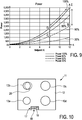
- FIG. 10 A simplified view from above onto such an induction hob 11 with a hob plate 12 is shown in Fig. 10 .
- This induction hob 11 has four induction heating coils 13a to 13d placed beneath the hob plate 12.
- an operating control having at least one microcontroller for analyzing the electrical measures mentioned before operating elements 18 and the luminous display 19 are provided.
- a round-circular pot 20 with a round-circular pot base is placed on the hob plate above induction heating coil 13.
- pot 20 In an initial position shown in dashed line, they are concentric and, accordingly, their center points are one over the other or identical, respectively.
- pot 20 is slightly smaller than induction heating coil 13.
- Fig. 1 shows that if now the pot 20 is moved from its initial position in dashed line to the new position in solid line at its right hand, which is a movement to the right, power P supplied to the induction heating coil 13 for inductively heating pot 20 is reduced. How much the power P is reduced in relation to a distance between the center points of induction heating coil 13 and pot 20 is not yet shown here. This has been discussed before and will be discussed in further detail hereinafter.
- Fig. 2 shows in a corresponding simple manner that pot 20 has been moved from its initial position in dashed line, in which pot 20 has protruded slightly to the right over induction heating coil 13, into a concentric position directly above induction heating coil 13.
- power P for the induction heating coil 13 is increased, as is indicated in Fig. 2 .
- a direction of the relative movement does not matter in these embodiments, so the movement is irrespective of whether it is to the right or to the left or up as long as the distance has become smaller.
- Fig. 3 shows an induction hob 11 where induction heating coil 13 is provided with coil turns 14 in spiral manner as is common in the art.
- a center point 16 of the induction heating coil 13 is shown with a small cross having a vertical and a horizontal line. It is also possible to realize the invention with an induction heating coil that does not have a circular form or circumference, but a square form or a rectangular form. It is then also possible to define a center point, preferably a center point of extension, as well as an area of such an induction heating coil, to compare them to the center point or the coverage by area of the pot.
- the position of induction heating coil 13 should be marked on the top surface of hob plate, preferably in a way known in the art by imprinting with weight or grey color. It is possible to mark the center point 16 of induction heating coil 13 or only the circumference or, preferably, both of them.
- hob 11 is provided with three sensor coils 22a to 22c, which are evenly distributed along the circumference of induction heating coil 13. They can be constructed and operated according to the prior art mentioned in the introductory part of the description.
- the sensor coils 22a to 22c can each detect whether they are covered at all by pot 20 and whether this is a complete coverage or only a partial coverage.
- a position of pot 20 can be calculated, or a coverage, respectively. This is also known in the prior art mentioned before.
- a fourth sensor coil 22d of the same construction is provided over the coil center point 16. This also helps to exactly locate position and/or coverage of the pot 20 above the induction heating coil 13. Also the electric parameters of the power supply to induction heating coil 13 can be used to determine whether and with which coverage by area the induction heating coil 13 is covered by a pot 20. This is also known in the prior art.
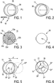
- Fig. 4 shows pot 20 in view of above.
- Pot 20 has a pot center point 21 in the form of an oblique cross.
- a pot base has the same diameter and form as the pot itself, a variation might be in the order of only some millimeters.
- pot 20 in dashed lines is concentrically placed above induction heating coil 13. Their respective center points 16 and 21' are identical.
- pot 20 in solid line to a position corresponding to Fig. 1 , wherein the distance d between their respective center points 16 and 21 is shown.
- Such a rather small movement can for example mean that the power P for the power supply to the induction heating coil 13 is reduced, possibly for about 30% to 40%.
- pot 20 has been heated in its initial position in dashed line with maximum power, it is now heated in the position with solid line only with 60% to 70% of the maximum power.
- pot 20" in dotted lines has been moved even further away from the induction heating coil or their center points 16 and 21" respectively, the power is reduced even more. Due to the coverage by area that is now obviously very small, for example about 10% of the area of pot 20, the power can be reduced to the minimum power, which may for example be only 10% to 15% of the maximum power. In corresponding manner, due to this relatively large distance between the center points 16 and 21", the power can be reduced to the minimum power mentioned before.
- induction heating coil 13 with its center point 16 is the same as before.
- pot 20 is now much smaller than before, with its diameter being about 60% of the diameter of induction heating coil 13.
- pot 20" is about concentrically over center point 16 of induction heating coil 13. This means that pot 20" cannot be moved any closer to induction heating coil 13 or in a position more concentrical or with more coverage anyway. So the power supplied to induction heating coil 13 should be at its maximum.
- pot 20' In the position of pot 20' in dashed line, pot 20' has been moved significantly down and to the left in relation to center point 16. Apart from pot 20 being most probably much too small for induction heating coil 13, its area would still be completely covered by induction heating coil 13 in spite of the relatively significant movement. But as a distance between the center points is now significant, for example about 20% of the diameter of induction heating coil 13, which means 3 cm to 5 cm, a movement of pot 20 from the dashed-dotted position to the dashed position should result in a reduction of power supplied to the induction heating coil 13. As an example, the power may be reduced for about 20% to 30%.
- pot 20 is moved even more to the side, which is shown with pot 20 in continuous line, the distance between the center points is now even somewhat larger and about 25% to 30% of the diameter of induction heating coil 13. This means that a power reduction with regard to maximum power should be about 30% to 40%, although pot 20 is still fully covered by induction heating coil 13, which means that it can be inductively heated in a largely homogeneous way.
- Fig. 6 mainly serves for illustrative purposes to show that it may be preferred that a change of the power supplied to the induction heating coil can even take place by relative movement of the pot 20 with its center point 21 to center point 16 of induction heating coil 13, which may be used for a power reduction even if the pot 20 is still largely or fully covered by the induction heating coil. This shows the focus on the movement of the pot relative to the induction heating coil.
- a reduction of inductively coupling energy into the base of pot 20 for heating it is not only varied with coverage of induction heating coil and pot, such that those parts of the pot not covering the induction heating coil are not heated any more automatically.
- the relative movement of the pot to the induction heating coil is used as a way for the operator positively expressing the wish to change the power supplied to the induction heating coil, either increasing power or reducing the power. It is of course preferable to indicate the power that is currently supplied to the induction heating coil by displaying it, as can be taken from Fig. 1 . This enables the operator to control whether the manual movement of the pot has resulted in a change of the power supplied to the induction heating coil as wanted. Such a power display can help the operator in addition to watching the pot and the cooking process in the pot.
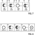
- Fig. 7 it is shown in the first position that the relative position between the center point of the pot 20 and the center point of the induction heating coil 13 as a distance amounts to about some cm, or about 25% of the diameter of the induction heating coil 13. This results in the power supplied to the induction heating coil 13 to be set at 90% of a maximum power. In this case this maximum power is 5 kW, and 90% of it are 4.5 kW.
- the pot 20 has been moved to the right somewhat such that its outer rim does but slightly reach over the center point of the induction heating coil 13. This is the maximum distance that the induction heating coil 13 may still heat the pot 20. So if the pot 20 has now been moved even further away from the induction heating coil 13, or their center points respectively, the power supplied to the induction heating coil 13 is reduced even further.
- This can in this example with a setpoint for the induction heating coil 13 set at its maximum, which can be a maximum setpoint 12, be a power reduction of 50% resulting in 2.5 kW. So this 2.5 kW is the new power supplied to the induction heating coil 13 for heating the pot 20.
- pot 20 in a third position is moved back over the induction heating coil 13 such that their center points are concentric to each other, the power is of course increased to its maximum. This is 100% in this case, resulting in 5 kW supplied to the induction heating coil 13 for heating the pot 20. Then the pot 20 is moved again to the right away from the induction heating coil 13 in the fourth position as the same position described before for the second position, and the same power supply is set.
- the power in the second and in the fourth position can be even more reduced, for example down to between 10% and 40%, for example 25%.
- a power reduction with movement is then more rapid so less space is needed around the induction heating coil 13 for the pot to be moved around.
- the number for the percentage in these two positions could be for example "25%" instead of "50%".
- Fig. 8 a sequence of positions of the pot 20 and the induction heating coil 13 similar as to Fig. 7 are provided with the difference that, in addition to relative movement of the pot 20, the setpoint K of the power to be supplied to the induction heating coil 13 is being changed also.
- the setpoint K for the power is set to 12, corresponding to the maximum setpoint with a maximum power of the induction heating coil 13.
- Fig. 9 a correlation between different curves for power in W over the chosen setpoint is shown as well as how the pot 20 can be moved between them for setting the power supplied to the induction heating coil 13.
- the power to be supplied to the induction heating coil 13 is 100% of the setpoint 12 resulting in 5 kW as described before. This is the maximum power.
- This position A with its power setting of 5 kW is also to be taken form Fig. 9 .
- the power is reduced to 50% by moving the pot 20 to the right away from the center point of the induction heating coil 13.
- the setpoint is, however, not changed. So according to Fig. 9 , the power supplied to the induction heating coil 13 is decreased to 50% or 2.5 kW, respectively. This power reduction between points A and B has been made only by movement of the pot 20 relative to the induction heating coil 13.
- Fig. 9 It can be taken from Fig. 9 that, for example starting at point A, there are two ways to reduce the power supplied to the induction heating coil 13. The first way is by moving the pot 20 away from the induction heating coil 13. The second way is to reduce the setpoint, which is the power originally intended to be supplied to the induction heating coil 13.
- the reduction of the power by moving the pot 20 away from the induction heating coil 13 to only 50% of the power originally set for the induction heating coil 13 is only an example. In other embodiments, such a reduction can be for much more, for example down to 20% or only 10% of the power originally set for the induction heating coil. Then the options for a user to change a power supplied to the induction heating coil 13 for inductively heating the pot 20 are more numerous and an induction hob can be operated with more degree of freedom.
Landscapes
- Physics & Mathematics (AREA)
- Electromagnetism (AREA)
- General Induction Heating (AREA)
Priority Applications (1)
| Application Number | Priority Date | Filing Date | Title |
|---|---|---|---|
| EP20153023.5A EP3855868A1 (fr) | 2020-01-22 | 2020-01-22 | Procédé de commande de l'alimentation électrique fournie à une bobine de chauffage par induction d'une table de cuisson à induction et table de cuisson à induction |
Applications Claiming Priority (1)
| Application Number | Priority Date | Filing Date | Title |
|---|---|---|---|
| EP20153023.5A EP3855868A1 (fr) | 2020-01-22 | 2020-01-22 | Procédé de commande de l'alimentation électrique fournie à une bobine de chauffage par induction d'une table de cuisson à induction et table de cuisson à induction |
Publications (1)
| Publication Number | Publication Date |
|---|---|
| EP3855868A1 true EP3855868A1 (fr) | 2021-07-28 |
Family
ID=69187599
Family Applications (1)
| Application Number | Title | Priority Date | Filing Date |
|---|---|---|---|
| EP20153023.5A Pending EP3855868A1 (fr) | 2020-01-22 | 2020-01-22 | Procédé de commande de l'alimentation électrique fournie à une bobine de chauffage par induction d'une table de cuisson à induction et table de cuisson à induction |
Country Status (1)
| Country | Link |
|---|---|
| EP (1) | EP3855868A1 (fr) |
Citations (11)
| Publication number | Priority date | Publication date | Assignee | Title |
|---|---|---|---|---|
| EP0967839A2 (fr) * | 1998-06-05 | 1999-12-29 | BSH Bosch und Siemens Hausgeräte GmbH | Plaque de cuisson munie d'une unité de commande dans le but de déterminer le niveau de puissance fournie |
| EP1787393A1 (fr) | 2004-09-09 | 2007-05-23 | E.G.O. ELEKTRO-GERÄTEBAU GmbH | Procede de caracterisation optique d'un interrupteur tactile et cet interrupteur tactile |
| WO2008058614A1 (fr) | 2006-11-15 | 2008-05-22 | E.G.O. Elektro-Gerätebau GmbH | Zone de cuisson à induction, table de cuisson à induction et procédé d'excitation |
| EP2087770A1 (fr) | 2006-11-09 | 2009-08-12 | Menu-System AG | Procédé de commande d'un appareil de cuisson par induction, et appareil de cuisson par induction |
| EP2309647A2 (fr) | 2009-10-07 | 2011-04-13 | E.G.O. ELEKTRO-GERÄTEBAU GmbH | Dispositif de commande d'un appareil électrique |
| WO2012095732A1 (fr) * | 2011-01-11 | 2012-07-19 | Elatronic Ag | Système de chauffage par induction ayant une commande de puissance autorégulatrice |
| EP2706816A1 (fr) * | 2012-09-05 | 2014-03-12 | E.G.O. ELEKTRO-GERÄTEBAU GmbH | Procédé de commande pour un champ de cuisson et champ de cuisson |
| EP2830220A1 (fr) | 2013-07-18 | 2015-01-28 | E.G.O. Elektro-Gerätebau GmbH | Élément de commande pour un dispositif de commande et dispositif de commande |
| EP3026981A1 (fr) | 2014-11-25 | 2016-06-01 | E.G.O. ELEKTRO-GERÄTEBAU GmbH | Plaque de cuisson a induction et procede de commande d'une plaque de cuisson a induction |
| EP3079443A1 (fr) | 2015-04-10 | 2016-10-12 | E.G.O. ELEKTRO-GERÄTEBAU GmbH | Plaque de cuisson à induction et support souple pour une plaque de cuisson à induction |
| EP3313145A1 (fr) * | 2016-10-18 | 2018-04-25 | Electrolux Appliances Aktiebolag | Table de cuisson à induction et procédé de contrôle de position optimale d'un récipient de cuisson sur la table de cuisson à induction |
-
2020
- 2020-01-22 EP EP20153023.5A patent/EP3855868A1/fr active Pending
Patent Citations (11)
| Publication number | Priority date | Publication date | Assignee | Title |
|---|---|---|---|---|
| EP0967839A2 (fr) * | 1998-06-05 | 1999-12-29 | BSH Bosch und Siemens Hausgeräte GmbH | Plaque de cuisson munie d'une unité de commande dans le but de déterminer le niveau de puissance fournie |
| EP1787393A1 (fr) | 2004-09-09 | 2007-05-23 | E.G.O. ELEKTRO-GERÄTEBAU GmbH | Procede de caracterisation optique d'un interrupteur tactile et cet interrupteur tactile |
| EP2087770A1 (fr) | 2006-11-09 | 2009-08-12 | Menu-System AG | Procédé de commande d'un appareil de cuisson par induction, et appareil de cuisson par induction |
| WO2008058614A1 (fr) | 2006-11-15 | 2008-05-22 | E.G.O. Elektro-Gerätebau GmbH | Zone de cuisson à induction, table de cuisson à induction et procédé d'excitation |
| EP2309647A2 (fr) | 2009-10-07 | 2011-04-13 | E.G.O. ELEKTRO-GERÄTEBAU GmbH | Dispositif de commande d'un appareil électrique |
| WO2012095732A1 (fr) * | 2011-01-11 | 2012-07-19 | Elatronic Ag | Système de chauffage par induction ayant une commande de puissance autorégulatrice |
| EP2706816A1 (fr) * | 2012-09-05 | 2014-03-12 | E.G.O. ELEKTRO-GERÄTEBAU GmbH | Procédé de commande pour un champ de cuisson et champ de cuisson |
| EP2830220A1 (fr) | 2013-07-18 | 2015-01-28 | E.G.O. Elektro-Gerätebau GmbH | Élément de commande pour un dispositif de commande et dispositif de commande |
| EP3026981A1 (fr) | 2014-11-25 | 2016-06-01 | E.G.O. ELEKTRO-GERÄTEBAU GmbH | Plaque de cuisson a induction et procede de commande d'une plaque de cuisson a induction |
| EP3079443A1 (fr) | 2015-04-10 | 2016-10-12 | E.G.O. ELEKTRO-GERÄTEBAU GmbH | Plaque de cuisson à induction et support souple pour une plaque de cuisson à induction |
| EP3313145A1 (fr) * | 2016-10-18 | 2018-04-25 | Electrolux Appliances Aktiebolag | Table de cuisson à induction et procédé de contrôle de position optimale d'un récipient de cuisson sur la table de cuisson à induction |
Similar Documents
| Publication | Publication Date | Title |
|---|---|---|
| EP3291643B1 (fr) | Appareil de cuisson et son procédé de commande | |
| EP2252130B1 (fr) | Dispositif de cuisson électromagnétique | |
| US20160150600A1 (en) | Induction hob and method for controlling an induction hob | |
| KR102026770B1 (ko) | 인덕션레인지 | |
| US9609697B2 (en) | Cooktop and method for operating a cooktop | |
| KR101904642B1 (ko) | 유도 가열 조리기기 | |
| JP5645781B2 (ja) | 誘導加熱調理器及びそのプログラム | |
| EP2991447B1 (fr) | Cuisinière à induction | |
| EP2453715B1 (fr) | Appareil ménager et procédé de centrage d'un appareil posé sur un appareil ménager | |
| KR20120109965A (ko) | 유도가열조리기의 제어방법 | |
| US20120138590A1 (en) | Lighting system for use with a cooktop appliance and method for assembling the same | |
| KR20140014934A (ko) | 유도가열조리기 및 그 제어방법 | |
| EP2618633A1 (fr) | Cuiseur thermique à induction | |
| US20200008272A1 (en) | Induction heating cooker | |
| JP5044977B2 (ja) | 誘導加熱調理器 | |
| WO2016181653A1 (fr) | Ustensile de cuisine à chauffage par induction | |
| US11805577B2 (en) | Induction cooker | |
| ES2845753T3 (es) | Método de funcionamiento de una encimera de cocción con varios dispositivos de calentamiento | |
| EP3855868A1 (fr) | Procédé de commande de l'alimentation électrique fournie à une bobine de chauffage par induction d'une table de cuisson à induction et table de cuisson à induction | |
| JP7154321B2 (ja) | 誘導加熱調理器 | |
| KR20180015972A (ko) | 조리장치 및 그 제어방법 | |
| JP6827163B2 (ja) | 誘導加熱調理器 | |
| JP5233862B2 (ja) | 電磁調理器 | |
| KR20180129201A (ko) | 유도 가열 조리기기 | |
| US11910511B2 (en) | Induction heating cooking apparatus |
Legal Events
| Date | Code | Title | Description |
|---|---|---|---|
| PUAI | Public reference made under article 153(3) epc to a published international application that has entered the european phase |
Free format text: ORIGINAL CODE: 0009012 |
|
| STAA | Information on the status of an ep patent application or granted ep patent |
Free format text: STATUS: THE APPLICATION HAS BEEN PUBLISHED |
|
| AK | Designated contracting states |
Kind code of ref document: A1 Designated state(s): AL AT BE BG CH CY CZ DE DK EE ES FI FR GB GR HR HU IE IS IT LI LT LU LV MC MK MT NL NO PL PT RO RS SE SI SK SM TR |
|
| STAA | Information on the status of an ep patent application or granted ep patent |
Free format text: STATUS: REQUEST FOR EXAMINATION WAS MADE |
|
| 17P | Request for examination filed |
Effective date: 20211214 |
|
| RBV | Designated contracting states (corrected) |
Designated state(s): AL AT BE BG CH CY CZ DE DK EE ES FI FR GB GR HR HU IE IS IT LI LT LU LV MC MK MT NL NO PL PT RO RS SE SI SK SM TR |
|
| GRAP | Despatch of communication of intention to grant a patent |
Free format text: ORIGINAL CODE: EPIDOSNIGR1 |
|
| STAA | Information on the status of an ep patent application or granted ep patent |
Free format text: STATUS: GRANT OF PATENT IS INTENDED |
|
| INTG | Intention to grant announced |
Effective date: 20240426 |