EP3855578B1 - Connector assembly - Google Patents
Connector assembly Download PDFInfo
- Publication number
- EP3855578B1 EP3855578B1 EP20209081.7A EP20209081A EP3855578B1 EP 3855578 B1 EP3855578 B1 EP 3855578B1 EP 20209081 A EP20209081 A EP 20209081A EP 3855578 B1 EP3855578 B1 EP 3855578B1
- Authority
- EP
- European Patent Office
- Prior art keywords
- connector
- outer member
- connector body
- present
- inner structure
- Prior art date
- Legal status (The legal status is an assumption and is not a legal conclusion. Google has not performed a legal analysis and makes no representation as to the accuracy of the status listed.)
- Active
Links
Images


Classifications
-
- H—ELECTRICITY
- H01—ELECTRIC ELEMENTS
- H01R—ELECTRICALLY-CONDUCTIVE CONNECTIONS; STRUCTURAL ASSOCIATIONS OF A PLURALITY OF MUTUALLY-INSULATED ELECTRICAL CONNECTING ELEMENTS; COUPLING DEVICES; CURRENT COLLECTORS
- H01R13/00—Details of coupling devices of the kinds covered by groups H01R12/70 or H01R24/00 - H01R33/00
- H01R13/62—Means for facilitating engagement or disengagement of coupling parts or for holding them in engagement
- H01R13/627—Snap or like fastening
- H01R13/6271—Latching means integral with the housing
- H01R13/6272—Latching means integral with the housing comprising a single latching arm
-
- H—ELECTRICITY
- H01—ELECTRIC ELEMENTS
- H01R—ELECTRICALLY-CONDUCTIVE CONNECTIONS; STRUCTURAL ASSOCIATIONS OF A PLURALITY OF MUTUALLY-INSULATED ELECTRICAL CONNECTING ELEMENTS; COUPLING DEVICES; CURRENT COLLECTORS
- H01R13/00—Details of coupling devices of the kinds covered by groups H01R12/70 or H01R24/00 - H01R33/00
- H01R13/46—Bases; Cases
- H01R13/502—Bases; Cases composed of different pieces
-
- H—ELECTRICITY
- H01—ELECTRIC ELEMENTS
- H01R—ELECTRICALLY-CONDUCTIVE CONNECTIONS; STRUCTURAL ASSOCIATIONS OF A PLURALITY OF MUTUALLY-INSULATED ELECTRICAL CONNECTING ELEMENTS; COUPLING DEVICES; CURRENT COLLECTORS
- H01R13/00—Details of coupling devices of the kinds covered by groups H01R12/70 or H01R24/00 - H01R33/00
- H01R13/62—Means for facilitating engagement or disengagement of coupling parts or for holding them in engagement
- H01R13/629—Additional means for facilitating engagement or disengagement of coupling parts, e.g. aligning or guiding means, levers, gas pressure electrical locking indicators, manufacturing tolerances
- H01R13/631—Additional means for facilitating engagement or disengagement of coupling parts, e.g. aligning or guiding means, levers, gas pressure electrical locking indicators, manufacturing tolerances for engagement only
- H01R13/6315—Additional means for facilitating engagement or disengagement of coupling parts, e.g. aligning or guiding means, levers, gas pressure electrical locking indicators, manufacturing tolerances for engagement only allowing relative movement between coupling parts, e.g. floating connection
-
- H—ELECTRICITY
- H01—ELECTRIC ELEMENTS
- H01R—ELECTRICALLY-CONDUCTIVE CONNECTIONS; STRUCTURAL ASSOCIATIONS OF A PLURALITY OF MUTUALLY-INSULATED ELECTRICAL CONNECTING ELEMENTS; COUPLING DEVICES; CURRENT COLLECTORS
- H01R13/00—Details of coupling devices of the kinds covered by groups H01R12/70 or H01R24/00 - H01R33/00
- H01R13/62—Means for facilitating engagement or disengagement of coupling parts or for holding them in engagement
- H01R13/639—Additional means for holding or locking coupling parts together, after engagement, e.g. separate keylock, retainer strap
-
- H—ELECTRICITY
- H01—ELECTRIC ELEMENTS
- H01R—ELECTRICALLY-CONDUCTIVE CONNECTIONS; STRUCTURAL ASSOCIATIONS OF A PLURALITY OF MUTUALLY-INSULATED ELECTRICAL CONNECTING ELEMENTS; COUPLING DEVICES; CURRENT COLLECTORS
- H01R24/00—Two-part coupling devices, or either of their cooperating parts, characterised by their overall structure
- H01R24/005—Two-part coupling devices, or either of their cooperating parts, characterised by their overall structure requiring successive relative motions to complete the coupling, e.g. bayonet type
-
- H—ELECTRICITY
- H01—ELECTRIC ELEMENTS
- H01R—ELECTRICALLY-CONDUCTIVE CONNECTIONS; STRUCTURAL ASSOCIATIONS OF A PLURALITY OF MUTUALLY-INSULATED ELECTRICAL CONNECTING ELEMENTS; COUPLING DEVICES; CURRENT COLLECTORS
- H01R13/00—Details of coupling devices of the kinds covered by groups H01R12/70 or H01R24/00 - H01R33/00
- H01R13/46—Bases; Cases
- H01R13/502—Bases; Cases composed of different pieces
- H01R13/506—Bases; Cases composed of different pieces assembled by snap action of the parts
-
- H—ELECTRICITY
- H01—ELECTRIC ELEMENTS
- H01R—ELECTRICALLY-CONDUCTIVE CONNECTIONS; STRUCTURAL ASSOCIATIONS OF A PLURALITY OF MUTUALLY-INSULATED ELECTRICAL CONNECTING ELEMENTS; COUPLING DEVICES; CURRENT COLLECTORS
- H01R13/00—Details of coupling devices of the kinds covered by groups H01R12/70 or H01R24/00 - H01R33/00
- H01R13/64—Means for preventing incorrect coupling
- H01R13/641—Means for preventing incorrect coupling by indicating incorrect coupling; by indicating correct or full engagement
Definitions
- This invention relates to a connector assembly comprising a first connector and a second connector mateable with each other.
- US 2003/211785 A1 discloses a split-type connector assembly according to the preamble of claim 1. Further, this type of connector assembly is disclosed in CN207542475U (Patent Document 1), the content of which is incorporated herein by reference.
- Patent Document 1 discloses a connector assembly 90 comprising a first connector 92 and a second connector 95 which are mateable with each other along a front-rear direction.
- the first connector 92 comprises an inner structure 93 and an outer member 94, the inner structure 93 including a first connector body 932, the outer member 94 being attached to the inner structure 93.
- the second connector 95 comprises an inner structure 96 and an outer member 97, the inner structure 96 including a second connector body 962, the outer member 97 being attached to the inner structure 96.
- the outer member 94 of the first connector 92 is formed with a lock projection 942.
- the outer member 97 of the second connector 95 is formed with a lock groove 972.
- the second connector For a connector assembly as in Patent Document 1, the second connector needs to be inserted into the first connector along a mating direction (front-rear direction) until the mated state is locked. During this insertion, the end of the second connector body might be occasionally brought into abutment with an innermost portion of the first connector body before the mated state is locked. In such a case, when the mated state is locked, the end of the second connector body might be pressed against the innermost portion of the first connector body to be damaged.
- the existing technique has a drawback which might cause damage to the connector body, which is at least one of the first connector body and the second connector body, during a mating operation in which the first connector is mated with the second connector.
- the second connector Upon a mating operation of a second connector with a first connector in an existing connector assembly, the second connector is allowed to be moved along a front-rear direction either until an outer member of the first connector is brought into abutment with an outer member of the second connector or until an inner structure of the first connector is brought into abutment with an inner structure of the second connector, so that the mated state can be locked.
- a connector body of the first connector might be pressed against a connector body of the second connector because of manufacturing or assembling tolerances of various members of the first connector and the second connector. Theoretically, this problem can be solved by substantially eliminating the tolerances. However, considering manufacturing cost, such a solution is not practical.
- the inventor of the present invention has invented a new mechanism based on the consideration described above.
- the second connector is allowed to be moved along the front-rear direction until the inner structure of the second connector is brought into abutment with the outer member of the first connector while the mated state is locked by the outer member of the first connector and the outer member of the second connector.
- the connector assembly of the present invention which has this mechanism, damage to the connector body thereof can be prevented while tolerances thereof are allowed.
- the present invention provides the connector assembly described below.
- the second connector is moved forward along the front-rear direction to be mated with the first connector.
- the second abutment portion of the second inner structure is brought into abutment with the first abutment portion of the first outer member so that a further forward movement of the second connector is prevented.
- This mechanism prevents a movement of the second connector body of the second connector to a position at which the second connector body is brought into abutment with the first connector body of the first connector.
- a rearward movement of the second connector relative to the first connector is regulated by the second lock surface of the second outer member and the first lock surface of the first outer member which face each other in the front-rear direction.
- a forward movement of the second connector relative to the first connector is regulated by the second regulation portion of the second outer member and the first regulation portion of the first outer member which face each other in the front-rear direction.
- the position of the second lock surface of the second outer member in the front-rear direction is designed in consideration of tolerances so that the second lock surface can be located apart from the first lock surface of the first outer member under the mated state.
- the position of the second regulation portion of the second outer member in the front-rear direction is designed in consideration of tolerances so that the second regulation portion can be located apart from the first regulation portion of the first outer member under the mated state.
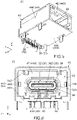
- a connector assembly 10 comprises a first connector 20 and a second connector 50.
- the first connector 20 is a receptacle.
- the first connector 20 is mounted on a circuit board (not shown) when used.
- the second connector 50 is a plug.
- the second connector 50 is connected to a cable 80 when used.
- the first connector 20 of the present embodiment is an on-board receptacle connector
- the second connector 50 of the present embodiment is a cable plug connector.
- the first connector 20 is a so-called angle type receptacle.
- the present invention is not limited thereto but is applicable to various connector assemblies.
- the first connector 20 may be a plug
- the second connector 50 may be a receptacle.
- the first connector 20 may be a cable connector similar to the second connector 50 and may be connected to a cable when used.
- the first connector 20 and the second connector 50 are mateable with each other along a front-rear direction (X-direction).
- the first connector 20 and the second connector 50 illustrated in Fig. 1 are under a separated state where they are separated from each other.
- the first connector 20 illustrated in Fig. 1 is located forward of the second connector 50.
- the second connector 50 under the separated state is moved forward, or moved along the positive X-direction, and toward the first connector 20, the first connector 20 and the second connector 50 change their state into a mated state, or a state shown in Fig. 2 , where they are mated with each other.
- the second connector 50 is mateable with the first connector 20 along the X-direction under the separated state where the first connector 20 is located forward of the second connector 50 in the X-direction. Under the mated state, the first connector 20 and the second connector 50 are electrically connected with each other, so that an electronic device (not shown) in which the circuit board (not shown) of the first connector 20 is installed is electrically connected with another electronic device (not shown) connected to the cable 80.
- the first connector 20 of the present embodiment comprises a first inner structure 30 and a first outer member 40.
- the first inner structure 30 is a member which works to electrically connect the first connector 20 and the second connector 50 under the mated state with each other.
- the first outer member 40 is a member which works to lock the mated state.
- the first outer member 40 is attached to the first inner structure 30. More specifically, the first inner structure 30 is inserted into the first outer member 40 from the front, so that the first connector 20 is fabricated.
- the first connector 20 of the present embodiment comprises only the first inner structure 30 and the first outer member 40.
- the present invention is not limited thereto.
- the first connector 20 may further comprise another member in addition to the first inner structure 30 and the first outer member 40.
- the first inner structure 30 comprises a first connector body 32.
- the first connector body 32 of the present embodiment comprises a first inner shell 34 made of conductor, a first holding member 36 made of insulator, a plurality of first terminals 38 each made of conductor and an alignment member 39 made of insulator.
- the first holding member 36 is formed of a plurality of members which are combined to each other.
- the first holding member 36 has a flat-plate portion 362.
- the flat-plate portion 362 is a rear part (negative X-side part) of the first holding member 36 and extends along a horizontal plane (XY-plane).
- the first terminals 38 are held by the first holding member 36.
- Each of the first terminals 38 has one end which is fixed on and connected to the circuit board (not shown) via soldering, etc. when the first connector 20 is used.
- Each of the first terminals 38 has the other end which is exposed from the flat-plate portion 362 and is electrically connected with the second connector 50 (see Fig. 1 ) under the mated state.
- the first inner shell 34 encloses the flat-plate portion 362 in a perpendicular plane (YZ-plane) perpendicular to the X-direction and defines an outer periphery of a rear part of the first connector body 32 in the YZ-plane.
- the alignment member 39 arranges some of the first terminals 38 in the horizontal plane.
- the first inner structure 30 of the present embodiment comprises only the first connector body 32 which has the aforementioned structure.
- the present invention is not limited thereto, but the structure of the first inner structure 30 can be variously modified as necessary.
- the first inner structure 30 may further comprise a member other than the first connector body 32.
- the first connector body 32 may comprise another member in addition to the aforementioned members.
- the first outer member 40 of the present embodiment comprises a first outer shell 42 made of conductor and a first outer housing 44 made of insulator.
- the first outer housing 44 of the present embodiment has an upper plate 442, a bottom plate 444, two side plates 446 and a back plate 448.
- the upper plate 442 is located on an upper side (positive Z-side) of the first outer housing 44 in an upper-lower direction (Z-direction) perpendicular to the X-direction and extends along the XY-plane.
- the bottom plate 444 is located on a lower side (negative Z-side) of the first outer housing 44 and extends along the XY-plane.
- the side plates 446 are located on opposite sides of the first outer housing 44, respectively, in a lateral direction (Y-direction) perpendicular to both the X-direction and the Z-direction and extend in parallel to each other along a predetermined plane (XZ-plane).
- the back plate 448 is located at a front end (positive X-side end) of the first outer housing 44 and extends along the YZ-plane.
- the upper plate 442, the bottom plate 444 and the two side plates 446 of the first outer housing 44 form a first outer-peripheral portion 441.
- the first outer member 40 of the present embodiment has the first outer-peripheral portion 441.
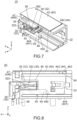
- the first connector 20 is formed with a first receiving portion 22 which is defined by the first outer-peripheral portion 441 and the back plate 448.
- the first receiving portion 22 is a space enclosed by the first outer-peripheral portion 441 in the YZ-plane and opens rearward along the negative X-direction.
- the back plate 448 is located at a front end of the first receiving portion 22.
- the first outer housing 44 of the present embodiment has a holding wall 48 and a projecting portion 49 in addition to the aforementioned portions.
- the holding wall 48 and the projecting portion 49 are located within the first receiving portion 22.
- the holding wall 48 is a cylindrical portion which opens forward and rearward.
- the holding wall 48 is provided on the middle of the back plate 448 in the YZ-plane and projects rearward from the back plate 448.
- the projecting portion 49 is provided on the middle of the holding wall 48 in the Y-direction.
- the projecting portion 49 protrudes downward along the negative Z-direction from a lower surface (negative Z-side surface) of the holding wall 48, and projects rearward from the back plate 448 beyond a rear end (negative X-side end) of the holding wall 48.
- the projecting portion 49 of the present embodiment is apart from the bottom plate 444 in the Z-direction, and a gap 45 is formed between the projecting portion 49 and the bottom plate 444.
- the first inner shell 34 of the first connector body 32 has a shape corresponding to the inner space of the holding wall 48 in the YZ-plane.
- the first connector body 32 is inserted into the first outer member 40 from the front so that the first inner shell 34 is fit into the holding wall 48.
- the thus-inserted first connector body 32 is held by the first outer member 40.
- the holding wall 48 sandwiches and presses the first inner shell 34 so that the first inner shell 34 cannot be moved.
- the first inner structure 30 of the present embodiment is held so as to be unmovable relative to the first outer member 40.
- the first outer housing 44 of the present embodiment has a lock hole 46.
- the lock hole 46 of the present embodiment is a hole formed in the upper plate 442.
- the lock hole 46 has a rectangular shape in the XY-plane.
- the lock hole 46 is located at the middle of the upper plate 442 in the Y-direction and passes through the upper plate 442 in the Z-direction.
- the first outer shell 42 of the present embodiment is a single metal plate with bends.
- the first outer shell 42 is attached to an outer periphery of the first outer housing 44 in the YZ-plane and mainly covers the upper plate 442 and the side plates 446.
- the first outer member 40 of the present embodiment comprises the first outer shell 42 and the first outer housing 44 each of which has the structure as described above.
- the present invention is not limited thereto, but the structure of the first outer member 40 can be variously modified.
- the first outer shell 42 may be provided as necessary.
- the second connector 50 of the present embodiment comprises a second inner structure 60 and a second outer member 70.
- the second inner structure 60 is a member which works together with the first inner structure 30 of the first connector 20 to electrically connect the first connector 20 and the second connector 50 under the mated state with each other.
- the second outer member 70 is a member which works together with the first outer member 40 of the first connector 20 to lock the mated state.
- the second outer member 70 is attached to the second inner structure 60. More specifically, the second inner structure 60 is inserted into the second outer member 70 from behind, so that the second connector 50 is fabricated.
- the second connector 50 of the present embodiment comprises only the second inner structure 60 and the second outer member 70.
- the present invention is not limited thereto.
- the second connector 50 may further comprise another member in addition to the second inner structure 60 and the second outer member 70.
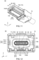
- the second inner structure 60 of the present embodiment comprises a second connector body 62 and a protection member 61 made of insulator.
- the second connector body 62 is connected to the cable 80 via a relay board 82.
- the protection member 61 is molded so as to cover a connection portion which includes the relay board 82 and connects the second connector body 62 and the cable 80 with each other.
- the thus-formed protection member 61 is securely fixed around the cable 80 and protects the cable 80.
- the second connector body 62 is fixed to a front end of the protection member 61 and projects forward from the protection member 61.
- the second connector body 62 of the present embodiment is partially embedded in the protection member 61 and is connected to the cable 80, so that the second connector 50 is attached to the cable 80.
- an attachment method of the second connector 50 to the cable 80 is not specifically limited.
- the second inner structure 60 of the present embodiment roughly has the aforementioned structure.
- the present invention is not limited thereto.
- the second inner structure 60 may comprise only the second connector body 62.
- the second inner structure 60 may further comprise another member in addition to the protection member 61 and the second connector body 62.
- the second connector body 62 of the present embodiment comprises a second inner shell 64 made of conductor, a second holding member 66 made of insulator and a plurality of second terminals 68 each made of conductor.
- the second holding member 66 is formed of a plurality of members which are combined to each other.
- the second terminals 68 are held by the second holding member 66.
- the second inner shell 64 enclosed the second holding member 66 in the YZ-plane.
- Each of the second terminals 68 has one end which is connected to a conductive wire (not shown) of the cable 80 via the relay board 82.
- Each of second terminals 68 has the other end which projects forward from the second holding member 66. Referring to Fig.
- the other ends of the second terminals 68 are brought into contact with the first terminals 38 of the second connector 50 under the mated state, respectively, so that the cable 80 connected to the second inner structure 60 is electrically connected with the circuit board (not shown) connected to the first inner structure 30.
- the second connector body 62 of the present embodiment comprises only the second inner shell 64, the second holding member 66 and the second terminals 68 each of which has the structure as described above.
- the present invention is not limited thereto.
- the second connector body 62 may further comprise another member in addition to the second inner shell 64, the second holding member 66 and the second terminals 68.
- the second outer member 70 of the present embodiment comprises a second outer housing 74 made of insulator.
- the second outer housing 74 of the present embodiment has an upper plate 742, a bottom plate 744 and two side plates 746.
- the upper plate 742 is located on an upper side of the second outer housing 74 and extends along the XY-plane.
- the bottom plate 744 is located on a lower side of the second outer housing 74 and extends along the XY-plane.
- the side plates 746 are located on opposite sides of the second outer housing 74 in the Y-direction, respectively, and extend in parallel to each other along the XZ-plane.
- the upper plate 742, the bottom plate 744 and the two side plates 746 of the second outer housing 74 form a second outer-peripheral portion 741.
- the second outer member 70 of the present embodiment has the second outer-peripheral portion 741.
- the second inner structure 60 is inserted into the second outer-peripheral portion 741 from behind together with an end of the cable 80.
- the thus-inserted second inner structure 60 is held by the second outer-peripheral portion 741.
- the thus-held second inner structure 60 and the second outer member 70 form a cable harness together with the cable 80.
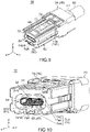
- the second connector 50 is formed with a second receiving portion 54 which is defined by a front part (positive X-side part) of the second outer-peripheral portion 741.
- the second receiving portion 54 is a space enclosed by the second outer-peripheral portion 741 in the YZ-plane and opens forward.
- the protection member 61 has a front end 612 which is located at a rear end of the second receiving portion 54.
- the second outer-peripheral portion 741 of the present embodiment has a recessed portion 745R and an insertion portion 745.
- the recessed portion 745R is a recess which is recessed downward.
- the recessed portion 745R is formed in the middle of the bottom plate 744 in the Y-direction.
- the recessed portion 745R extends along the X-direction and opens forward.
- the recessed portion 745R communicates with the second receiving portion 54 in the Z-direction.
- the insertion portion 745 is a part of the bottom plate 744 located under the recessed portion 745R.
- the insertion portion 745 has a flat-plate shape in parallel to the XY-plane and extends along the X-direction.
- the second outer housing 74 of the present embodiment has a spring portion 75 in addition to the aforementioned portions.
- the spring portion 75 is formed of a part of the upper plate 742 which is partially cut off from the upper plate 742.
- the spring portion 75 has opposite ends in the X-direction which are fixed to the upper plate 742.
- the spring portion 75 has opposite sides in the Y-direction which are separated from the upper plate 742.
- the spring portion 75 is resiliently deformable because of the aforementioned structure.
- the spring portion 75 is formed with a lock projection 76.
- the lock projection 76 is located at the middle of the spring portion 75 in the X-direction.
- the lock projection 76 is movable in the Z-direction in accordance with resilient deformation of the spring portion 75.
- the second outer housing 74 of the present embodiment has a lance 78 and a stopper 79.
- the lance 78 and the stopper 79 are located in the second outer-peripheral portion 741.
- the lance 78 projects upward and forward from the bottom plate 744.
- the lance 78 is partially received in an engagement recess 614 which is a recess provided in the protection member 61.
- the lance 78 is engaged with the engagement recess 614 to prevent the second inner structure 60 from coming off the second outer housing 74.
- the stopper 79 When the lance 78 is in contact with a front inner wall of the engagement recess 614, the stopper 79 is located rearward of a stopped portion 616 which is a part of the protection member 61 and apart from the stopped portion 616 by a predetermined distance DP.
- the stopped portion 616 When the second inner structure 60 is moved forward, the stopped portion 616 is brought into abutment with the stopper 79 so that the forward movement of the second inner structure 60 is stopped.
- the second inner structure 60 of the present embodiment is held by the second outer member 70 so as to be movable relative to the second outer member 70 along the X-direction by the predetermined distance DP.
- the lance 78 of the second outer member 70 defines the rear limit position which is the rearmost position of the second inner structure 60 relative to the second outer member 70
- the stopper 79 of the second outer member 70 defines the front limit position which is the frontmost position of the second inner structure 60 relative to the second outer member 70.
- the present invention is not limited thereto.
- the rear limit position and the front limit position of the second inner structure 60 may be defined by any part or any member.
- the second outer member 70 of the present embodiment comprises only the second outer housing 74 which has the structure as described above.
- the present invention is not limited thereto, but the structure of the second outer member 70 can be variously modified.
- the second outer member 70 may further comprise another member in addition to the second outer housing 74.
- the second connector 50 has a mating portion 52.
- the mating portion 52 is a front part of the second connector 50 and has a shape insertable into the first receiving portion 22 of the first connector 20.
- the lock projection 76 of the second connector 50 is moved forward along a lower surface of the upper plate 442 of the first connector 20 while the spring portion 75 is bent.
- the lock projection 76 is moved to the lock hole 46 of the first connector 20, and the spring portion 75 returns to its initial shape. As a result, the lock projection 76 is received in the lock hole 46.
- the mated state of the first connector 20 and the second connector 50 is locked by the first outer member 40 of the first connector 20 and the second outer member 70 of the second connector 50.
- the second connector body 62 might be brought into abutment with the first connector body 32 before the mated state is locked. In such a case, when the mated state is locked, the second connector body 62 might be pressed against the first connector body 32 to be damaged.
- the connector assembly 10 of the present embodiment has a damage prevention mechanism for preventing damage to the first connector body 32 and the second connector body 62.
- explanation will be made about the damage prevention mechanism of the connector assembly 10.
- the first outer member 40 of the first connector 20 has a first lock surface 462, a first regulation portion 47 and a first abutment portion 492.
- the first lock surface 462 faces forward.
- the first regulation portion 47 faces rearward.
- the first abutment portion 492 faces rearward.
- the first lock surface 462 of the present embodiment is a surface of the rear inner wall of the lock hole 46.
- the first regulation portion 47 is a rear surface of the back plate 448.
- the first abutment portion 492 is a rear surface of the projecting portion 49.
- Each of the first regulation portion 47 and the first abutment portion 492 is located in the first receiving portion 22.
- the present invention is not limited thereto.
- each of the first lock surface 462, the first regulation portion 47 and the first abutment portion 492 may be any part of the first outer member 40, provided that it faces in the aforementioned direction.
- the arrangement of the first lock surface 462, the first regulation portion 47 and the first abutment portion 492 is not limited to that of the present embodiment.
- the second inner structure 60 of the second connector 50 has a second abutment portion (front end) 612.
- the second outer member 70 of the second connector 50 has a second lock surface 762 and a second regulation portion 77.
- the second lock surface 762 faces rearward.
- the second regulation portion 77 faces forward.
- the second abutment portion 612 faces forward.
- the second lock surface 762 of the present embodiment is the rear surface of the lock projection 76.
- the second regulation portion 77 is a front end 70F of the second outer member 70.
- the second abutment portion 612 is the front end of the protection member 61 and is located in the second receiving portion 54.
- each of the second lock surface 762 and the second regulation portion 77 may be any part of the second outer member 70, provided that it faces in the aforementioned direction.
- the second abutment portion 612 may be any part of the second inner structure 60, provided that it faces in the aforementioned direction.
- the arrangement of the second lock surface 762, the second regulation portion 77 and the second abutment portion 612 is not limited to that of the present embodiment.
- the operator of the mating operation recognizes that the second connector 50 is completely mated with the first connector 20 when the second abutment portion 612 is brought into abutment with the first abutment portion 492 so that the forward movement of the second connector 50 relative to the first connector 20 is stopped.
- the second abutment portion 612 is brought into abutment with the first abutment portion 492 when the second connector 50 is mated with the first connector 20, and this abutment prevents a further forward movement of the second connector 50.
- the position of each of the first abutment portion 492 and the second abutment portion 612 in the X-direction is designed in consideration of tolerances of various members included in the first connector 20 and the second connector 50, so that the second connector body 62 of the second connector 50 is prevented from being moved to a position at which the second connector body 62 is brought into abutment with the first connector body 32 of the first connector 20.
- the first connector body 32 of the present embodiment has a facing portion 322.
- the second connector body 62 of the present embodiment has an end portion 622.
- the facing portion 322 and the end portion 622 are apart from each other and face each other in the X-direction.
- This mechanism prevents damage to the first connector body 32 and the second connector body 62 which might be caused when the facing portion 322 and the end portion 622 are brought into abutment with each other and are pressed against each other.
- the first inner structure 30 is prevented from being displaced or removed from the first outer member 40, which might be caused due to a forward force applied to the first inner structure 30.
- the second connector 50 when the second connector 50 is mated with the first connector 20, the second connector body 62 is received in the first connector body 32.
- the facing portion 322 is a part of the first holding member 36, and the end portion 622 is a front end 64F of the second inner shell 64.
- each of the facing portion 322 and the end portion 622 may be provided on any member.
- the first connector body 32 when the second connector 50 is mated with the first connector 20, the first connector body 32 may be received in the second connector body 62. In this modification, the first connector body 32 may have an end portion, and the second connector body 62 may have a facing portion.
- the second lock surface 762 faces the first lock surface 462 in the X-direction and regulates a rearward movement of the second connector 50 relative to the first connector 20.
- the thus-located second lock surface 762 may be in contact with the first lock surface 462.
- the second regulation portion 77 faces the first regulation portion 47 in the X-direction and regulates a forward movement of the second connector 50 relative to the first connector 20.
- the thus-located second regulation portion 77 may be in contact with the first regulation portion 47.
- a movement of the second connector 50 in the X-direction relative to the first connector 20 is regulated by the second lock surface 762 and the first lock surface 462 facing each other in the X-direction and is regulated by the second regulation portion 77 and the first regulation portion 47 facing each other in the X-direction.
- the mated state is locked by the first outer member 40 of the first connector 20 and the second outer member 70 of the second connector 50.
- the position of the second lock surface 762 in the X-direction is designed in consideration of tolerances of various members included in the first connector 20 and the second connector 50 so that the second lock surface 762 can be located apart from the first lock surface 462 under the mated state.
- the position of the second regulation portion 77 in the X-direction is designed in consideration of the aforementioned tolerances so that the second regulation portion 77 can be located apart from the first regulation portion 47 under the mated state.
- the first regulation portion 47 and the first lock surface 462 of the first connector 20 are apart from each other by a first distance D1 in the X-direction.
- the second regulation portion 77 and the second lock surface 762 of the second connector 50 are apart from each other by a second distance D2 in the X-direction.
- the first regulation portion 47 is located forward of the first lock surface 462, and the first distance D1 is longer than the second distance D2.
- the second outer member 70 is movable relative to the first outer member 40 along the X-direction.
- the present embodiment provides the connector assembly 10 having the damage prevention mechanism which allows tolerances and prevents damage to the first connector body 32 and the second connector body 62 during the mating operation of the first connector 20 with the second connector 50.
- each of the first regulation portion 47, the first lock surface 462, the second regulation portion 77 and the second lock surface 762 is a plane in parallel to the YZ-plane.
- the present invention is not limited thereto.
- each of the first regulation portion 47, the first lock surface 462, the second regulation portion 77 and the second lock surface 762 may be a sloping surface oblique to the X-direction.
- Each of the first distance D1 and the second distance D2 described above is a distance in consideration of such a structure.
- each of the first distance D1 and the second distance D2 is a distance on an imaginary line which extends in parallel to the X-direction and which passes through all the first regulation portion 47, the first lock surface 462, the second regulation portion 77 and the second lock surface 762.
- first distance D1 is longer than the second distance D2 defined as described above (hereafter, simply referred to as "second distance D2").
- the second inner structure 60 of the present embodiment is movable relative to the second outer member 70 along the X-direction by the predetermined distance DP (see Fig. 14 ).
- the second outer member 70 is movable relative to the first outer member 40 along the X-direction by the predetermined distance DP under the completely mated state where the first abutment portion 492 and the second abutment portion 612 are in abutment with each other.
- the present embodiment allows a movement of the second outer member 70 relative to the second inner structure 60 and thereby enables a movement of the second outer member 70 relative to the first outer member 40 so that damage to the first connector body 32 and the second connector body 62 is prevented.
- the present invention is not limited thereto.
- the first inner structure 30 of the first connector 20 may be movable relative to the first outer member 40 similarly to the second connector 50.
- the first regulation portion 47 of the present embodiment is located forward of the first lock surface 462.
- the present invention is not limited thereto, but the first regulation portion 47 may be located rearward of the first lock surface 462.
- the first distance D1 should be designed to be shorter than the second distance D2.
- this modification provides the connector assembly 10 having the damage prevention mechanism which prevents damage to the first connector body 32 and the second connector body 62 during the mating operation of the first connector 20 with the second connector 50.
- the first distance D1 should be longer than the second distance D2, and in another structure in which the first regulation portion 47 is located rearward of the first lock surface 462, the first distance D1 should be shorter than the second distance D2.
- the aforementioned damage prevention mechanism of the connector assembly 10 will be explained here in another viewpoint.
- the second regulation portion 77 and the second lock surface 762 of the present embodiment are located between the first regulation portion 47 and the first lock surface 462 so as to allow an unstable, slight movement of the second outer member 70 relative to the first outer member 40 under the mated state.
- the present invention is not limited thereto.
- the second regulation portion 77 and the second lock surface 762 may sandwich the first regulation portion 47 and the first lock surface 462 therebetween so as to allow an unstable, slight movement of the second outer member 70 relative to the first outer member 40 under the mated state.
- the connector assembly 10 of the present embodiment can be further variously modified in addition to the already explained modifications. Hereafter, explanation will be made about those modifications.
- the first outer member 40 of the first connector 20, which is a receptacle is provided with the first abutment portion 492 and the lock hole 46.
- the second inner structure 60 of the second connector 50, which is a plug is provided with the second abutment portion 612.
- the second outer member 70 is provided with the lock projection 76.
- the present invention is not limited thereto.
- a first connector is modified to be a plug
- a first outer member of the first connector may be provided with a first abutment portion and a lock projection.
- a second inner structure of a second connector which is a receptacle, may be provided with a second abutment portion, and a second outer member may be provided with a lock hole.
- the lock hole 46 is provided so as to be unmovable relative to the first outer member 40, while the lock projection 76 is provided so as to be movable relative to the second outer member 70.
- a lock projection may be provided on the first outer member 40 so as to be unmovable relative to the first outer member 40.
- a part having a lock hole may be provided on the second outer member 70 so as to be movable relative to the second outer member 70.
- the first abutment portion 492 is located rearward of the first connector body 32. According to this structure, in the mating operation of the second connector 50 with the first connector 20, the second abutment portion 612 can be reliably brought into abutment with the first abutment portion 492 before the second connector body 62 is close to the first connector body 32. Thus, damage to the first connector body 32 and the second connector body 62 can be more reliably prevented.
- the present invention is not limited thereto.
- the position of the first abutment portion 492 may be designed as necessary.
- the bottom plate 444 and the projecting portion 49 of the first outer-peripheral portion 441 face each other with the gap 45 located therebetween in the Z-direction.
- the first outer-peripheral portion 441 is located outward of the first abutment portion 492 in the YZ-plane while the gap 45 is partially located between the first outer-peripheral portion 441 and the first abutment portion 492.
- the second outer-peripheral portion 741 of the second outer member 70 of the present embodiment covers the second connector body 62 in the YZ-plane. Referring to Figs.
- the projecting portion 49 of the first outer member 40 is inserted into the recessed portion 745R (see Fig. 10 ) of the second outer member 70, and the insertion portion 745 of the bottom plate 744 is inserted into the gap 45.
- the insertion portion 745 of the second outer-peripheral portion 741 is located inside the first outer-peripheral portion 441 in the YZ-plane and is located in the gap 45.
- the second receiving portion 54 can be entirely covered by the second outer-peripheral portion 741 with no hole, so that intrusion of foreign materials into the second receiving portion 54 can be prevented.
- the present invention is not limited thereto.
- the first outer-peripheral portion 441 may be located outward of the first abutment portion 492 in the YZ-plane while the gap 45 is, at least in part, located between the first outer-peripheral portion 441 and the first abutment portion 492.
- the second outer-peripheral portion 741 may be, at least in part, located inside the first outer-peripheral portion 441 in the YZ-plane and may be, at least in part, located in the gap 45.
- the front end 70F of the second outer member 70 is located forward of the front end 64F of the second connector body 62.
- the front end 64F of the second connector body 62 is located within the second receiving portion 54. This structure more reliably prevents damage to the second connector body 62.
- the present invention is not limited thereto.
- the position of the second connector body 62 relative to the second outer member 70 may be designed as necessary.
- the second abutment portion 612 is located rearward of the front end 64F of the second connector body 62.
- This structure enables the second connector body 62 to be deeply inserted into the first receiving portion 22 (see Fig. 8 ), so that the first connector body 32 and the second connector body 62 can be more stably connected.
- the present invention is not limited thereto.
- the position of the second abutment portion 612 relative to the second connector body 62 may be designed as necessary.
Landscapes
- Details Of Connecting Devices For Male And Female Coupling (AREA)
Applications Claiming Priority (1)
| Application Number | Priority Date | Filing Date | Title |
|---|---|---|---|
| JP2020009806A JP7348090B2 (ja) | 2020-01-24 | 2020-01-24 | コネクタ組立体 |
Publications (2)
| Publication Number | Publication Date |
|---|---|
| EP3855578A1 EP3855578A1 (en) | 2021-07-28 |
| EP3855578B1 true EP3855578B1 (en) | 2023-03-01 |
Family
ID=73543213
Family Applications (1)
| Application Number | Title | Priority Date | Filing Date |
|---|---|---|---|
| EP20209081.7A Active EP3855578B1 (en) | 2020-01-24 | 2020-11-20 | Connector assembly |
Country Status (4)
| Country | Link |
|---|---|
| US (1) | US11309661B2 (enExample) |
| EP (1) | EP3855578B1 (enExample) |
| JP (1) | JP7348090B2 (enExample) |
| CN (1) | CN113258355B (enExample) |
Families Citing this family (8)
| Publication number | Priority date | Publication date | Assignee | Title |
|---|---|---|---|---|
| USD916661S1 (en) * | 2018-02-28 | 2021-04-20 | Molex, Llc | Connector housing |
| USD984382S1 (en) * | 2019-05-09 | 2023-04-25 | Ideal Industries, Inc. | Electrical connector |
| JP1670022S (enExample) * | 2020-05-29 | 2020-10-12 | ||
| JP1676724S (enExample) * | 2020-06-15 | 2021-01-18 | ||
| JP1678796S (enExample) * | 2020-06-15 | 2021-02-08 | ||
| JP1695883S (enExample) * | 2021-03-02 | 2021-09-27 | ||
| JP1695884S (enExample) * | 2021-03-02 | 2021-09-27 | ||
| JP1703880S (enExample) * | 2021-04-02 | 2022-01-04 |
Family Cites Families (20)
| Publication number | Priority date | Publication date | Assignee | Title |
|---|---|---|---|---|
| JP3067468B2 (ja) * | 1993-04-27 | 2000-07-17 | 住友電装株式会社 | コネクタ |
| JP3534013B2 (ja) * | 1999-10-06 | 2004-06-07 | 住友電装株式会社 | コネクタ |
| JP2003331989A (ja) * | 2002-05-08 | 2003-11-21 | Sumitomo Wiring Syst Ltd | 分割コネクタ |
| US7063577B2 (en) | 2002-05-08 | 2006-06-20 | Sumitomo Wiring Systems, Ltd. | Split-type connector assembly and method of assembling it |
| JP4278673B2 (ja) * | 2006-10-17 | 2009-06-17 | ヒロセ電機株式会社 | 電気コネクタ |
| US7666023B2 (en) * | 2008-05-22 | 2010-02-23 | Hon Hai Precision Ind. Co., Ltd. | Electrical connector with a latch coupled to a pull member |
| US8235744B1 (en) * | 2011-02-01 | 2012-08-07 | Delphi Technologies, Inc. | Electrical connection system including connector body with integral primary and secondary latch |
| CN202601982U (zh) * | 2012-06-08 | 2012-12-12 | 泰科电子(上海)有限公司 | 连接器组件和连接器产品 |
| US9461374B2 (en) * | 2013-03-15 | 2016-10-04 | Molex, Llc | Electrical connector assembly and connecting member thereof |
| JP2015153615A (ja) * | 2014-02-14 | 2015-08-24 | 株式会社オートネットワーク技術研究所 | コネクタ |
| JP6230471B2 (ja) | 2014-04-09 | 2017-11-15 | ホシデン株式会社 | コネクタ |
| JP2016110851A (ja) * | 2014-12-08 | 2016-06-20 | 矢崎総業株式会社 | コネクタ |
| JP6647825B2 (ja) | 2015-09-29 | 2020-02-14 | 日本航空電子工業株式会社 | コネクタ及びコネクタ組立体 |
| JP6525854B2 (ja) | 2015-11-24 | 2019-06-05 | 日本航空電子工業株式会社 | コネクタ及びコネクタ組立体 |
| EP3373398B1 (en) * | 2017-03-10 | 2023-03-29 | TE Connectivity Germany GmbH | Connector assembly with improved lever gear transmission |
| JP6806606B2 (ja) | 2017-03-23 | 2021-01-06 | 日本航空電子工業株式会社 | コネクタ |
| JP6667965B2 (ja) * | 2017-08-31 | 2020-03-18 | 矢崎総業株式会社 | コネクタ |
| CN207542475U (zh) | 2017-11-29 | 2018-06-26 | 番禺得意精密电子工业有限公司 | 电连接器 |
| CN109950746B (zh) * | 2017-12-20 | 2020-12-22 | 番禺得意精密电子工业有限公司 | 电连接器组合 |
| CN208045870U (zh) | 2018-04-03 | 2018-11-02 | 富誉电子科技(淮安)有限公司 | 母端插座、公端插头及电连接器组合 |
-
2020
- 2020-01-24 JP JP2020009806A patent/JP7348090B2/ja active Active
- 2020-11-05 US US17/089,868 patent/US11309661B2/en active Active
- 2020-11-17 CN CN202011289208.1A patent/CN113258355B/zh active Active
- 2020-11-20 EP EP20209081.7A patent/EP3855578B1/en active Active
Also Published As
| Publication number | Publication date |
|---|---|
| US11309661B2 (en) | 2022-04-19 |
| US20210234305A1 (en) | 2021-07-29 |
| CN113258355B (zh) | 2023-06-27 |
| JP7348090B2 (ja) | 2023-09-20 |
| JP2021118077A (ja) | 2021-08-10 |
| CN113258355A (zh) | 2021-08-13 |
| EP3855578A1 (en) | 2021-07-28 |
Similar Documents
| Publication | Publication Date | Title |
|---|---|---|
| EP3855578B1 (en) | Connector assembly | |
| US10333239B2 (en) | Connector | |
| EP1487065B1 (en) | Connector having an improved effect of preventing an unlocking lever from being damaged | |
| CN109616829B (zh) | 连接器 | |
| US20050287847A1 (en) | Connector in which reliable ground connection is assured | |
| HK1000400B (en) | Mountable connector for cable assembly | |
| EP3667834B1 (en) | Connector assembly | |
| US5775932A (en) | Electrical connector | |
| EP4138230B1 (en) | Connector assembly | |
| US20060281374A1 (en) | Electrical Connector | |
| US6364686B2 (en) | Electrical and/or optical connector with a latching arm | |
| JPH1021993A (ja) | コネクタ | |
| US20250015529A1 (en) | Connector | |
| CN106898916A (zh) | 连接器 | |
| JP4987624B2 (ja) | 分割式コネクタ | |
| US11888266B2 (en) | Connector shielding with a guiding protrusion | |
| JP7435373B2 (ja) | コネクタ | |
| US9196993B2 (en) | Connector unit | |
| JP5201101B2 (ja) | コネクタ | |
| WO2022054456A1 (ja) | シールドコネクタ | |
| JP7303985B2 (ja) | コネクタ | |
| JP3123427B2 (ja) | 雄型コネクタ | |
| JPS61161679A (ja) | レセプタクル用電気コネクタ | |
| CN114824899B (zh) | 连接器 | |
| CN112952410B (zh) | 连接器 |
Legal Events
| Date | Code | Title | Description |
|---|---|---|---|
| PUAI | Public reference made under article 153(3) epc to a published international application that has entered the european phase |
Free format text: ORIGINAL CODE: 0009012 |
|
| STAA | Information on the status of an ep patent application or granted ep patent |
Free format text: STATUS: THE APPLICATION HAS BEEN PUBLISHED |
|
| AK | Designated contracting states |
Kind code of ref document: A1 Designated state(s): AL AT BE BG CH CY CZ DE DK EE ES FI FR GB GR HR HU IE IS IT LI LT LU LV MC MK MT NL NO PL PT RO RS SE SI SK SM TR |
|
| STAA | Information on the status of an ep patent application or granted ep patent |
Free format text: STATUS: REQUEST FOR EXAMINATION WAS MADE |
|
| 17P | Request for examination filed |
Effective date: 20210929 |
|
| RBV | Designated contracting states (corrected) |
Designated state(s): AL AT BE BG CH CY CZ DE DK EE ES FI FR GB GR HR HU IE IS IT LI LT LU LV MC MK MT NL NO PL PT RO RS SE SI SK SM TR |
|
| STAA | Information on the status of an ep patent application or granted ep patent |
Free format text: STATUS: EXAMINATION IS IN PROGRESS |
|
| 17Q | First examination report despatched |
Effective date: 20211210 |
|
| RIC1 | Information provided on ipc code assigned before grant |
Ipc: H01R 13/506 20060101ALN20220719BHEP Ipc: H01R 13/641 20060101ALN20220719BHEP Ipc: H01R 13/631 20060101ALI20220719BHEP Ipc: H01R 13/639 20060101ALI20220719BHEP Ipc: H01R 13/627 20060101AFI20220719BHEP |
|
| GRAP | Despatch of communication of intention to grant a patent |
Free format text: ORIGINAL CODE: EPIDOSNIGR1 |
|
| STAA | Information on the status of an ep patent application or granted ep patent |
Free format text: STATUS: GRANT OF PATENT IS INTENDED |
|
| RIC1 | Information provided on ipc code assigned before grant |
Ipc: H01R 13/506 20060101ALN20220907BHEP Ipc: H01R 13/641 20060101ALN20220907BHEP Ipc: H01R 13/631 20060101ALI20220907BHEP Ipc: H01R 13/639 20060101ALI20220907BHEP Ipc: H01R 13/627 20060101AFI20220907BHEP |
|
| INTG | Intention to grant announced |
Effective date: 20220919 |
|
| GRAS | Grant fee paid |
Free format text: ORIGINAL CODE: EPIDOSNIGR3 |
|
| GRAA | (expected) grant |
Free format text: ORIGINAL CODE: 0009210 |
|
| STAA | Information on the status of an ep patent application or granted ep patent |
Free format text: STATUS: THE PATENT HAS BEEN GRANTED |
|
| AK | Designated contracting states |
Kind code of ref document: B1 Designated state(s): AL AT BE BG CH CY CZ DE DK EE ES FI FR GB GR HR HU IE IS IT LI LT LU LV MC MK MT NL NO PL PT RO RS SE SI SK SM TR |
|
| REG | Reference to a national code |
Ref country code: GB Ref legal event code: FG4D |
|
| REG | Reference to a national code |
Ref country code: CH Ref legal event code: EP Ref country code: AT Ref legal event code: REF Ref document number: 1551664 Country of ref document: AT Kind code of ref document: T Effective date: 20230315 |
|
| REG | Reference to a national code |
Ref country code: DE Ref legal event code: R096 Ref document number: 602020008445 Country of ref document: DE |
|
| REG | Reference to a national code |
Ref country code: IE Ref legal event code: FG4D |
|
| REG | Reference to a national code |
Ref country code: SE Ref legal event code: TRGR |
|
| REG | Reference to a national code |
Ref country code: LT Ref legal event code: MG9D |
|
| REG | Reference to a national code |
Ref country code: NL Ref legal event code: MP Effective date: 20230301 |
|
| PG25 | Lapsed in a contracting state [announced via postgrant information from national office to epo] |
Ref country code: RS Free format text: LAPSE BECAUSE OF FAILURE TO SUBMIT A TRANSLATION OF THE DESCRIPTION OR TO PAY THE FEE WITHIN THE PRESCRIBED TIME-LIMIT Effective date: 20230301 Ref country code: NO Free format text: LAPSE BECAUSE OF FAILURE TO SUBMIT A TRANSLATION OF THE DESCRIPTION OR TO PAY THE FEE WITHIN THE PRESCRIBED TIME-LIMIT Effective date: 20230601 Ref country code: LV Free format text: LAPSE BECAUSE OF FAILURE TO SUBMIT A TRANSLATION OF THE DESCRIPTION OR TO PAY THE FEE WITHIN THE PRESCRIBED TIME-LIMIT Effective date: 20230301 Ref country code: LT Free format text: LAPSE BECAUSE OF FAILURE TO SUBMIT A TRANSLATION OF THE DESCRIPTION OR TO PAY THE FEE WITHIN THE PRESCRIBED TIME-LIMIT Effective date: 20230301 Ref country code: HR Free format text: LAPSE BECAUSE OF FAILURE TO SUBMIT A TRANSLATION OF THE DESCRIPTION OR TO PAY THE FEE WITHIN THE PRESCRIBED TIME-LIMIT Effective date: 20230301 Ref country code: ES Free format text: LAPSE BECAUSE OF FAILURE TO SUBMIT A TRANSLATION OF THE DESCRIPTION OR TO PAY THE FEE WITHIN THE PRESCRIBED TIME-LIMIT Effective date: 20230301 |
|
| REG | Reference to a national code |
Ref country code: AT Ref legal event code: MK05 Ref document number: 1551664 Country of ref document: AT Kind code of ref document: T Effective date: 20230301 |
|
| PG25 | Lapsed in a contracting state [announced via postgrant information from national office to epo] |
Ref country code: PL Free format text: LAPSE BECAUSE OF FAILURE TO SUBMIT A TRANSLATION OF THE DESCRIPTION OR TO PAY THE FEE WITHIN THE PRESCRIBED TIME-LIMIT Effective date: 20230301 Ref country code: NL Free format text: LAPSE BECAUSE OF FAILURE TO SUBMIT A TRANSLATION OF THE DESCRIPTION OR TO PAY THE FEE WITHIN THE PRESCRIBED TIME-LIMIT Effective date: 20230301 Ref country code: GR Free format text: LAPSE BECAUSE OF FAILURE TO SUBMIT A TRANSLATION OF THE DESCRIPTION OR TO PAY THE FEE WITHIN THE PRESCRIBED TIME-LIMIT Effective date: 20230602 Ref country code: FI Free format text: LAPSE BECAUSE OF FAILURE TO SUBMIT A TRANSLATION OF THE DESCRIPTION OR TO PAY THE FEE WITHIN THE PRESCRIBED TIME-LIMIT Effective date: 20230301 |
|
| PG25 | Lapsed in a contracting state [announced via postgrant information from national office to epo] |
Ref country code: SM Free format text: LAPSE BECAUSE OF FAILURE TO SUBMIT A TRANSLATION OF THE DESCRIPTION OR TO PAY THE FEE WITHIN THE PRESCRIBED TIME-LIMIT Effective date: 20230301 Ref country code: RO Free format text: LAPSE BECAUSE OF FAILURE TO SUBMIT A TRANSLATION OF THE DESCRIPTION OR TO PAY THE FEE WITHIN THE PRESCRIBED TIME-LIMIT Effective date: 20230301 Ref country code: PT Free format text: LAPSE BECAUSE OF FAILURE TO SUBMIT A TRANSLATION OF THE DESCRIPTION OR TO PAY THE FEE WITHIN THE PRESCRIBED TIME-LIMIT Effective date: 20230703 Ref country code: EE Free format text: LAPSE BECAUSE OF FAILURE TO SUBMIT A TRANSLATION OF THE DESCRIPTION OR TO PAY THE FEE WITHIN THE PRESCRIBED TIME-LIMIT Effective date: 20230301 Ref country code: CZ Free format text: LAPSE BECAUSE OF FAILURE TO SUBMIT A TRANSLATION OF THE DESCRIPTION OR TO PAY THE FEE WITHIN THE PRESCRIBED TIME-LIMIT Effective date: 20230301 Ref country code: AT Free format text: LAPSE BECAUSE OF FAILURE TO SUBMIT A TRANSLATION OF THE DESCRIPTION OR TO PAY THE FEE WITHIN THE PRESCRIBED TIME-LIMIT Effective date: 20230301 |
|
| PG25 | Lapsed in a contracting state [announced via postgrant information from national office to epo] |
Ref country code: SK Free format text: LAPSE BECAUSE OF FAILURE TO SUBMIT A TRANSLATION OF THE DESCRIPTION OR TO PAY THE FEE WITHIN THE PRESCRIBED TIME-LIMIT Effective date: 20230301 Ref country code: IS Free format text: LAPSE BECAUSE OF FAILURE TO SUBMIT A TRANSLATION OF THE DESCRIPTION OR TO PAY THE FEE WITHIN THE PRESCRIBED TIME-LIMIT Effective date: 20230701 |
|
| REG | Reference to a national code |
Ref country code: DE Ref legal event code: R097 Ref document number: 602020008445 Country of ref document: DE |
|
| PLBE | No opposition filed within time limit |
Free format text: ORIGINAL CODE: 0009261 |
|
| STAA | Information on the status of an ep patent application or granted ep patent |
Free format text: STATUS: NO OPPOSITION FILED WITHIN TIME LIMIT |
|
| PG25 | Lapsed in a contracting state [announced via postgrant information from national office to epo] |
Ref country code: SI Free format text: LAPSE BECAUSE OF FAILURE TO SUBMIT A TRANSLATION OF THE DESCRIPTION OR TO PAY THE FEE WITHIN THE PRESCRIBED TIME-LIMIT Effective date: 20230301 Ref country code: DK Free format text: LAPSE BECAUSE OF FAILURE TO SUBMIT A TRANSLATION OF THE DESCRIPTION OR TO PAY THE FEE WITHIN THE PRESCRIBED TIME-LIMIT Effective date: 20230301 |
|
| 26N | No opposition filed |
Effective date: 20231204 |
|
| PG25 | Lapsed in a contracting state [announced via postgrant information from national office to epo] |
Ref country code: IT Free format text: LAPSE BECAUSE OF FAILURE TO SUBMIT A TRANSLATION OF THE DESCRIPTION OR TO PAY THE FEE WITHIN THE PRESCRIBED TIME-LIMIT Effective date: 20230301 |
|
| REG | Reference to a national code |
Ref country code: CH Ref legal event code: PL |
|
| PG25 | Lapsed in a contracting state [announced via postgrant information from national office to epo] |
Ref country code: MC Free format text: LAPSE BECAUSE OF FAILURE TO SUBMIT A TRANSLATION OF THE DESCRIPTION OR TO PAY THE FEE WITHIN THE PRESCRIBED TIME-LIMIT Effective date: 20230301 |
|
| PG25 | Lapsed in a contracting state [announced via postgrant information from national office to epo] |
Ref country code: LU Free format text: LAPSE BECAUSE OF NON-PAYMENT OF DUE FEES Effective date: 20231120 |
|
| PG25 | Lapsed in a contracting state [announced via postgrant information from national office to epo] |
Ref country code: CH Free format text: LAPSE BECAUSE OF NON-PAYMENT OF DUE FEES Effective date: 20231130 |
|
| PG25 | Lapsed in a contracting state [announced via postgrant information from national office to epo] |
Ref country code: MC Free format text: LAPSE BECAUSE OF FAILURE TO SUBMIT A TRANSLATION OF THE DESCRIPTION OR TO PAY THE FEE WITHIN THE PRESCRIBED TIME-LIMIT Effective date: 20230301 Ref country code: LU Free format text: LAPSE BECAUSE OF NON-PAYMENT OF DUE FEES Effective date: 20231120 Ref country code: CH Free format text: LAPSE BECAUSE OF NON-PAYMENT OF DUE FEES Effective date: 20231130 |
|
| REG | Reference to a national code |
Ref country code: BE Ref legal event code: MM Effective date: 20231130 |
|
| REG | Reference to a national code |
Ref country code: IE Ref legal event code: MM4A |
|
| PG25 | Lapsed in a contracting state [announced via postgrant information from national office to epo] |
Ref country code: IE Free format text: LAPSE BECAUSE OF NON-PAYMENT OF DUE FEES Effective date: 20231120 |
|
| PG25 | Lapsed in a contracting state [announced via postgrant information from national office to epo] |
Ref country code: BE Free format text: LAPSE BECAUSE OF NON-PAYMENT OF DUE FEES Effective date: 20231130 |
|
| PG25 | Lapsed in a contracting state [announced via postgrant information from national office to epo] |
Ref country code: IE Free format text: LAPSE BECAUSE OF NON-PAYMENT OF DUE FEES Effective date: 20231120 Ref country code: BE Free format text: LAPSE BECAUSE OF NON-PAYMENT OF DUE FEES Effective date: 20231130 |
|
| PG25 | Lapsed in a contracting state [announced via postgrant information from national office to epo] |
Ref country code: BG Free format text: LAPSE BECAUSE OF FAILURE TO SUBMIT A TRANSLATION OF THE DESCRIPTION OR TO PAY THE FEE WITHIN THE PRESCRIBED TIME-LIMIT Effective date: 20230301 |
|
| PG25 | Lapsed in a contracting state [announced via postgrant information from national office to epo] |
Ref country code: BG Free format text: LAPSE BECAUSE OF FAILURE TO SUBMIT A TRANSLATION OF THE DESCRIPTION OR TO PAY THE FEE WITHIN THE PRESCRIBED TIME-LIMIT Effective date: 20230301 |
|
| PGFP | Annual fee paid to national office [announced via postgrant information from national office to epo] |
Ref country code: DE Payment date: 20241001 Year of fee payment: 5 |
|
| PGFP | Annual fee paid to national office [announced via postgrant information from national office to epo] |
Ref country code: GB Payment date: 20241001 Year of fee payment: 5 |
|
| PGFP | Annual fee paid to national office [announced via postgrant information from national office to epo] |
Ref country code: SE Payment date: 20241001 Year of fee payment: 5 |
|
| PG25 | Lapsed in a contracting state [announced via postgrant information from national office to epo] |
Ref country code: CY Free format text: LAPSE BECAUSE OF FAILURE TO SUBMIT A TRANSLATION OF THE DESCRIPTION OR TO PAY THE FEE WITHIN THE PRESCRIBED TIME-LIMIT; INVALID AB INITIO Effective date: 20201120 |
|
| PG25 | Lapsed in a contracting state [announced via postgrant information from national office to epo] |
Ref country code: HU Free format text: LAPSE BECAUSE OF FAILURE TO SUBMIT A TRANSLATION OF THE DESCRIPTION OR TO PAY THE FEE WITHIN THE PRESCRIBED TIME-LIMIT; INVALID AB INITIO Effective date: 20201120 |
|
| PGFP | Annual fee paid to national office [announced via postgrant information from national office to epo] |
Ref country code: FR Payment date: 20250930 Year of fee payment: 6 |
|
| PG25 | Lapsed in a contracting state [announced via postgrant information from national office to epo] |
Ref country code: TR Free format text: LAPSE BECAUSE OF FAILURE TO SUBMIT A TRANSLATION OF THE DESCRIPTION OR TO PAY THE FEE WITHIN THE PRESCRIBED TIME-LIMIT Effective date: 20230301 |