EP3855570B1 - Elektrische anschlussklemme - Google Patents
Elektrische anschlussklemme Download PDFInfo
- Publication number
- EP3855570B1 EP3855570B1 EP20213982.0A EP20213982A EP3855570B1 EP 3855570 B1 EP3855570 B1 EP 3855570B1 EP 20213982 A EP20213982 A EP 20213982A EP 3855570 B1 EP3855570 B1 EP 3855570B1
- Authority
- EP
- European Patent Office
- Prior art keywords
- contact
- conduit
- clamping
- cover
- conductor
- Prior art date
- Legal status (The legal status is an assumption and is not a legal conclusion. Google has not performed a legal analysis and makes no representation as to the accuracy of the status listed.)
- Active
Links
Images


Classifications
-
- H—ELECTRICITY
- H01—ELECTRIC ELEMENTS
- H01R—ELECTRICALLY-CONDUCTIVE CONNECTIONS; STRUCTURAL ASSOCIATIONS OF A PLURALITY OF MUTUALLY-INSULATED ELECTRICAL CONNECTING ELEMENTS; COUPLING DEVICES; CURRENT COLLECTORS
- H01R4/00—Electrically-conductive connections between two or more conductive members in direct contact, i.e. touching one another; Means for effecting or maintaining such contact; Electrically-conductive connections having two or more spaced connecting locations for conductors and using contact members penetrating insulation
- H01R4/10—Electrically-conductive connections between two or more conductive members in direct contact, i.e. touching one another; Means for effecting or maintaining such contact; Electrically-conductive connections having two or more spaced connecting locations for conductors and using contact members penetrating insulation effected solely by twisting, wrapping, bending, crimping, or other permanent deformation
- H01R4/18—Electrically-conductive connections between two or more conductive members in direct contact, i.e. touching one another; Means for effecting or maintaining such contact; Electrically-conductive connections having two or more spaced connecting locations for conductors and using contact members penetrating insulation effected solely by twisting, wrapping, bending, crimping, or other permanent deformation by crimping
- H01R4/183—Electrically-conductive connections between two or more conductive members in direct contact, i.e. touching one another; Means for effecting or maintaining such contact; Electrically-conductive connections having two or more spaced connecting locations for conductors and using contact members penetrating insulation effected solely by twisting, wrapping, bending, crimping, or other permanent deformation by crimping for cylindrical elongated bodies, e.g. cables having circular cross-section
- H01R4/184—Electrically-conductive connections between two or more conductive members in direct contact, i.e. touching one another; Means for effecting or maintaining such contact; Electrically-conductive connections having two or more spaced connecting locations for conductors and using contact members penetrating insulation effected solely by twisting, wrapping, bending, crimping, or other permanent deformation by crimping for cylindrical elongated bodies, e.g. cables having circular cross-section comprising a U-shaped wire-receiving portion
-
- H—ELECTRICITY
- H01—ELECTRIC ELEMENTS
- H01R—ELECTRICALLY-CONDUCTIVE CONNECTIONS; STRUCTURAL ASSOCIATIONS OF A PLURALITY OF MUTUALLY-INSULATED ELECTRICAL CONNECTING ELEMENTS; COUPLING DEVICES; CURRENT COLLECTORS
- H01R12/00—Structural associations of a plurality of mutually-insulated electrical connecting elements, specially adapted for printed circuits, e.g. printed circuit boards [PCB], flat or ribbon cables, or like generally planar structures, e.g. terminal strips, terminal blocks; Coupling devices specially adapted for printed circuits, flat or ribbon cables, or like generally planar structures; Terminals specially adapted for contact with, or insertion into, printed circuits, flat or ribbon cables, or like generally planar structures
- H01R12/50—Fixed connections
- H01R12/51—Fixed connections for rigid printed circuits or like structures
- H01R12/515—Terminal blocks providing connections to wires or cables
-
- H—ELECTRICITY
- H01—ELECTRIC ELEMENTS
- H01R—ELECTRICALLY-CONDUCTIVE CONNECTIONS; STRUCTURAL ASSOCIATIONS OF A PLURALITY OF MUTUALLY-INSULATED ELECTRICAL CONNECTING ELEMENTS; COUPLING DEVICES; CURRENT COLLECTORS
- H01R11/00—Individual connecting elements providing two or more spaced connecting locations for conductive members which are, or may be, thereby interconnected, e.g. end pieces for wires or cables supported by the wire or cable and having means for facilitating electrical connection to some other wire, terminal, or conductive member, blocks of binding posts
- H01R11/01—Individual connecting elements providing two or more spaced connecting locations for conductive members which are, or may be, thereby interconnected, e.g. end pieces for wires or cables supported by the wire or cable and having means for facilitating electrical connection to some other wire, terminal, or conductive member, blocks of binding posts characterised by the form or arrangement of the conductive interconnection between the connecting locations
-
- H—ELECTRICITY
- H01—ELECTRIC ELEMENTS
- H01R—ELECTRICALLY-CONDUCTIVE CONNECTIONS; STRUCTURAL ASSOCIATIONS OF A PLURALITY OF MUTUALLY-INSULATED ELECTRICAL CONNECTING ELEMENTS; COUPLING DEVICES; CURRENT COLLECTORS
- H01R12/00—Structural associations of a plurality of mutually-insulated electrical connecting elements, specially adapted for printed circuits, e.g. printed circuit boards [PCB], flat or ribbon cables, or like generally planar structures, e.g. terminal strips, terminal blocks; Coupling devices specially adapted for printed circuits, flat or ribbon cables, or like generally planar structures; Terminals specially adapted for contact with, or insertion into, printed circuits, flat or ribbon cables, or like generally planar structures
- H01R12/50—Fixed connections
- H01R12/51—Fixed connections for rigid printed circuits or like structures
- H01R12/53—Fixed connections for rigid printed circuits or like structures connecting to cables except for flat or ribbon cables
-
- H—ELECTRICITY
- H01—ELECTRIC ELEMENTS
- H01R—ELECTRICALLY-CONDUCTIVE CONNECTIONS; STRUCTURAL ASSOCIATIONS OF A PLURALITY OF MUTUALLY-INSULATED ELECTRICAL CONNECTING ELEMENTS; COUPLING DEVICES; CURRENT COLLECTORS
- H01R4/00—Electrically-conductive connections between two or more conductive members in direct contact, i.e. touching one another; Means for effecting or maintaining such contact; Electrically-conductive connections having two or more spaced connecting locations for conductors and using contact members penetrating insulation
- H01R4/28—Clamped connections, spring connections
- H01R4/48—Clamped connections, spring connections utilising a spring, clip, or other resilient member
-
- H—ELECTRICITY
- H01—ELECTRIC ELEMENTS
- H01R—ELECTRICALLY-CONDUCTIVE CONNECTIONS; STRUCTURAL ASSOCIATIONS OF A PLURALITY OF MUTUALLY-INSULATED ELECTRICAL CONNECTING ELEMENTS; COUPLING DEVICES; CURRENT COLLECTORS
- H01R4/00—Electrically-conductive connections between two or more conductive members in direct contact, i.e. touching one another; Means for effecting or maintaining such contact; Electrically-conductive connections having two or more spaced connecting locations for conductors and using contact members penetrating insulation
- H01R4/28—Clamped connections, spring connections
- H01R4/48—Clamped connections, spring connections utilising a spring, clip, or other resilient member
- H01R4/4809—Clamped connections, spring connections utilising a spring, clip, or other resilient member using a leaf spring to bias the conductor toward the busbar
- H01R4/4846—Busbar details
- H01R4/4848—Busbar integrally formed with the spring
-
- H—ELECTRICITY
- H01—ELECTRIC ELEMENTS
- H01R—ELECTRICALLY-CONDUCTIVE CONNECTIONS; STRUCTURAL ASSOCIATIONS OF A PLURALITY OF MUTUALLY-INSULATED ELECTRICAL CONNECTING ELEMENTS; COUPLING DEVICES; CURRENT COLLECTORS
- H01R12/00—Structural associations of a plurality of mutually-insulated electrical connecting elements, specially adapted for printed circuits, e.g. printed circuit boards [PCB], flat or ribbon cables, or like generally planar structures, e.g. terminal strips, terminal blocks; Coupling devices specially adapted for printed circuits, flat or ribbon cables, or like generally planar structures; Terminals specially adapted for contact with, or insertion into, printed circuits, flat or ribbon cables, or like generally planar structures
- H01R12/50—Fixed connections
- H01R12/51—Fixed connections for rigid printed circuits or like structures
- H01R12/55—Fixed connections for rigid printed circuits or like structures characterised by the terminals
- H01R12/57—Fixed connections for rigid printed circuits or like structures characterised by the terminals surface mounting terminals
-
- H—ELECTRICITY
- H01—ELECTRIC ELEMENTS
- H01R—ELECTRICALLY-CONDUCTIVE CONNECTIONS; STRUCTURAL ASSOCIATIONS OF A PLURALITY OF MUTUALLY-INSULATED ELECTRICAL CONNECTING ELEMENTS; COUPLING DEVICES; CURRENT COLLECTORS
- H01R4/00—Electrically-conductive connections between two or more conductive members in direct contact, i.e. touching one another; Means for effecting or maintaining such contact; Electrically-conductive connections having two or more spaced connecting locations for conductors and using contact members penetrating insulation
- H01R4/28—Clamped connections, spring connections
- H01R4/48—Clamped connections, spring connections utilising a spring, clip, or other resilient member
- H01R4/4809—Clamped connections, spring connections utilising a spring, clip, or other resilient member using a leaf spring to bias the conductor toward the busbar
- H01R4/48185—Clamped connections, spring connections utilising a spring, clip, or other resilient member using a leaf spring to bias the conductor toward the busbar adapted for axial insertion of a wire end
- H01R4/4819—Clamped connections, spring connections utilising a spring, clip, or other resilient member using a leaf spring to bias the conductor toward the busbar adapted for axial insertion of a wire end the spring shape allowing insertion of the conductor end when the spring is unbiased
- H01R4/4823—Multiblade spring
-
- H—ELECTRICITY
- H01—ELECTRIC ELEMENTS
- H01R—ELECTRICALLY-CONDUCTIVE CONNECTIONS; STRUCTURAL ASSOCIATIONS OF A PLURALITY OF MUTUALLY-INSULATED ELECTRICAL CONNECTING ELEMENTS; COUPLING DEVICES; CURRENT COLLECTORS
- H01R4/00—Electrically-conductive connections between two or more conductive members in direct contact, i.e. touching one another; Means for effecting or maintaining such contact; Electrically-conductive connections having two or more spaced connecting locations for conductors and using contact members penetrating insulation
- H01R4/28—Clamped connections, spring connections
- H01R4/48—Clamped connections, spring connections utilising a spring, clip, or other resilient member
- H01R4/4809—Clamped connections, spring connections utilising a spring, clip, or other resilient member using a leaf spring to bias the conductor toward the busbar
- H01R4/484—Spring housing details
- H01R4/4842—Spring housing details the spring housing being provided with a single opening for insertion of a spring-activating tool
Definitions
- the invention relates to an electrical connection terminal with a contact cage which has a contact base, a contact cover and two contact side walls connecting the contact base and contact cover to one another, the contact base, contact cover and contact side walls together forming a conductor insertion channel, with a conductor clamping connection which is prestressed by at least one against an abutment is formed, and with an insertion bevel for a conductor formed in the area of the contact cover, the insertion bevel being formed by a guide wing (33) which originates from the contact cover (23) in the conductor insertion direction (x) and which is inclined towards the contact base (21). is executed.
- a terminal which forms a guide member. This is attached to the ceiling of the one-piece conductor entry channel and lies with its free end between the clamping legs of the clamping point.
- a generic electrical terminal is for example from EP 3 159 974 A1 known.
- This is a connection terminal for arrangement on a printed circuit board.
- the contact base of the contact cage forms a connection area at its front and rear end, viewed in the conductor insertion direction, which is contacted with the printed circuit board, in particular by a soldered connection.
- a connecting conductor can be inserted into the conductor insertion channel with its stripped end first.
- the conductor insertion channel is used to feed the conductor to a terminal point in which it is held.
- the clamping point can be opened via a release tool, which can be inserted into a parting line between the clamping spring and the counter bearing, as a result of which the clamping spring is separated from the counter bearing against a spring preload.
- This makes it possible to remove a conductor sitting between the abutment and the clamping spring from the connection terminal.
- connection terminal according to EP 3 159 974 A1 belonging insulating material housing arranged in the area of the contact cover from an inclined insertion surface. This is designed to be inclined from the contact cover to the contact base in the direction of the clamping point.
- connection terminals often measure no more than 3 to 4 mm in width with approximately the same height and a length of approximately 8 mm. Due to these very small dimensions, the insulating housings enclosing the connection terminals must be manufactured with great precision, especially if they also have a conductive function.
- the object of the invention is therefore to provide a generic connection terminal with a guide function that can be manufactured more easily and efficiently.
- connection terminal can be used with or without an insulating housing.
- the contact cover is designed in two parts with a parting line aligned in the conductor insertion direction, with the guide wing being connected to only one of the contact cover parts.
- the parting line divides the contact cover in half.
- a contact cover designed in this way ensures a symmetrical opening of the clamping springs forming the clamping point when a conductor is inserted. Both clamping springs are thus deflected to the same extent. This improves the grip of the conductor and is also PT29831-03EP essential for later opening of the clamping point. Only a symmetrical deflection of the clamping springs ensures that a release tool can have an opening effect on both clamping springs when it is pushed into the clamping point, which is due in particular to the small dimensions of the connecting terminal.
- the parting line which is usually unavoidable when forming a connection terminal from a sheet metal strip, can be optimally attached in the area of the contact cover, since here - in contrast to the contact side walls - no forces caused by the terminal point act.
- the abutment can be a rigid wall section connected, for example, to the contact base.
- the abutment is designed as a second clamping spring, with both clamping springs being prestressed in the direction of a vertical contact longitudinal center plane, ie being prestressed against one another.
- the free ends of the clamping springs rest against one another and can also have a clamping wedge formed on them. If there is a clamping wedge, the clamping wedges of both clamping springs face each other.
- clamping spring and/or the counter bearing have tool attachments for opening the clamping point.
- clamping point can be opened in order to remove a conductor sitting there from the connection terminal remove or insert the terminal point for inserting a conductor, for example a multi-wire conductor, into the terminal point without resistance.
- the guide wing has a free end facing away from the contact cover, which is arranged in front of the tool grip in the conductor insertion direction.
- this embodiment ensures that the guide wing does not impede a tool attack to open the clamping point.
- clamping spring and/or the counter bearing serve as a support for the guide wing, it is also ensured that the guide wing cannot get between the clamping springs - possibly after being spread by an opening tool - and thus prevent the closing of the clamping point.
- the conductor insertion channel prefferably has an essentially rectangular cross section, in which the contact side walls are aligned vertically with respect to the contact base and contact cover.
- the contact base and contact cover, as well as the contact side walls are essentially non-curved.
- the contact frame which is generally formed from a piece of sheet metal, only experiences a curvature in the corner areas forming in the transition between wall and floor or wall and ceiling, which is solely due to manufacturing reasons.
- the main advantage of this embodiment is that, compared to a round conductor insertion channel, a larger cross section is available with the same external dimensions in terms of height and width. This facilitates the automated insertion of connection conductors.
- both the clamping springs or clamping spring and counter bearing and the guide wing can be more easily molded onto non-curved wall, ceiling and floor sections of the conductor insertion channel, since both the clamping springs and the guide wing can generally only lose their optimal technical effect if these are non-curved components.
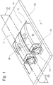
- an electrical connection terminal according to the invention is given the reference number 10 as a whole.
- the terminal 10 carries an insulating material housing 11 and is placed on a printed circuit board or circuit board 12 shown schematically.
- the insulating material housing 11 has a collar 13 which surrounds a conductor insertion recess 14 formed by the insulating material housing 11 and which is arranged in front of the conductor insertion opening 15 of the connecting terminal 10 in the conductor insertion direction x.
- the insulating material housing 11 has a tool recess 17 in its top wall 16, via which a tool (not shown) can be inserted into the insulating material housing 11 in order to open a clamping point 18 of the connection terminal 10.
- the insulating material housing 11 has a rear wall 19.
- the insulating material housing 11 has two side walls 20 lying opposite one another.
- the terminal 10 has a contact base 21 on which two contact side walls 22 are formed and extend approximately vertically in relation to the contact base 21 upwards.
- a contact cover 23 is formed onto the contact side walls 22 and is aligned approximately parallel to the contact base 21 .
- the contact base 21 surrounds a conductor insertion channel 24 with the contact side walls 22 and the contact cover 23.
- the contact base 21 At its end upstream of the conductor insertion opening 15 of the conductor insertion channel 24 in the insertion direction x, the contact base 21 has a first contact foot 25 and at its end downstream of the conductor insertion channel 24 in the conductor insertion direction x has a second contact foot 26.
- the first and second contact feet are arranged in a common plane. In the same plane as the contact feet 25 and 26 is also that section of the contact base 21 that forms the channel base 27 of the conductor insertion channel 24 is located.
- the contact base 21 is raised in relation to the plane of the contact bases 25, 26 in the direction of the contact cover.
- the contact side walls 22 originate from the section forming the channel base 27 of the contact base 21 and do not extend beyond the length of the channel base 27 in terms of their length measured in the conductor insertion direction x.
- the contact side walls 22 can also be referred to as channel side walls.
- the contact cover 23 extends over a maximum length corresponding to the duct base length in the conductor insertion direction x, so that the contact cover 23 can also be referred to as the duct cover.
- the duct cover 23 is formed in two parts, with a parting line 28 running in the conductor insertion direction x extending between the two cover parts. In the ideal case, the parting line divides the contact cover in half.
- a contact cover designed in this way ensures a symmetrical opening of the clamping springs forming the clamping point when a conductor is inserted. Both clamping springs are thus deflected to the same extent. This improves the hold of the conductor and is also essential for later opening of the terminal point. Only a symmetrical deflection of the clamping springs ensures that a release tool can have an opening effect on both clamping springs when it is pushed into the clamping point, which is due in particular to the small dimensions of the connecting terminal.
- the cross section of the conductor insertion channel 24 is essentially rectangular, in a preferred embodiment approximately square.
- the duct side walls 22, the duct base 21 and the duct cover 23 are essentially uncurved. They experience a curvature only in the corner areas in which the duct side walls 22 merge into the duct floor 21 or the duct cover 23 . These radii are essentially due to manufacturing reasons. These are bending radii that result from the production of the connecting terminal 10 in a stamping and bending process from a metallic stamped part.
- the rectangular, preferably square cross section of the conductor insertion channel 24 has the considerable advantage that the cross-sectional area is larger in terms of width and height than a round, in particular circular conductor insertion channel 24 with the same external dimensions. This simplifies the mechanical insertion of connection conductors, since slightly larger tolerances are possible with regard to the positioning of the insertion tool relative to the connection terminal.
- Two clamping springs 30 arise from the channel or contact side walls 22 in the conductor insertion direction x, the free ends of which meet in the region of a vertical longitudinal center plane (not shown) of the connecting terminal 10 running in the conductor insertion direction x.
- the mating free ends of the clamp legs are spring loaded.
- the clamping springs 30 are sufficiently close together with their free ends. Depending on the conductor cross-sections provided, even a gap between the free ends is tolerable.
- the clamping springs 30 form the clamping point 18 of the connection terminal.
- a tool grip 31 extends on each clamping spring 30 not shown opening tool are pushed to spread apart the clamping springs 30 and so open the terminal point 18 for resistance-free insertion or removal of a connecting conductor.
- a guide wing 33 emerges from the contact or channel cover 23 in the conductor insertion direction x and is designed inclined from the location of its connection to the contact cover 23 in the direction of the contact base 21. As a result, the free end of the guide wing 33 is closer to the contact base 21 than the guide wing root connected to the contact cover 23 .
- the guide wing 33 originates only from the first cover part 34.
- the second cover part 35 is held without guide wing.
- the guide wing 33 nevertheless spans the width of the channel, so that a conductor to be inserted cannot leave the channel or the clamping area downstream of the conductor insertion channel 24 upwards, ie in the direction away from the channel base.
- the guide vane 33 can rest on the clamping springs 30, which then form a support. This has the significant advantage that the maximum possible inclination of the guide wing 33 in the direction of the contact base 21 can be used for guiding the conductors. As can also be seen, the free end of the guide wing 33 is in the conductor insertion direction x in front of the tool attachments 31 of the clamping springs 30, so that free access to the tool attachments 31 is ensured.
- the guide vane 33 undergoes a trapezoidal expansion in its end section close to the free end, in order to prevent the free end of the guide vane from entering the terminal point 18 when the clamping point 18 is fully open, since this would cause the spread, opened position to be reset Prevent clamping springs 30 and thus the defect of the terminal 10 would mean.
- FIG. 3 now shows a representation accordingly 4 , except that here a connecting conductor 36, a cable with the stripped end, has been inserted in the conductor insertion direction x through the conductor insertion opening 15 and the conductor insertion channel 24 into the terminal point 18.
- the clamping springs 30 have undergone a spreading outwards, with a spring tension being built up which opposes the spreading movement.
- the unspecified clamping edges of the clamping springs 30 bear against the stripped end of the connection conductor 36 and hold it in place in the clamping point 18 against retraction forces.
- connection conductor 36 already mentioned was inserted into one of the two connection terminals.
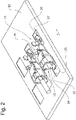
- the connection terminals 10 sit with their contact feet 25 and 26 on connection surfaces 37 of the circuit board 12 and are attached there in an electrically contacting manner, for example by a soldering process.
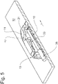
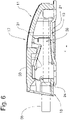
- the figures 5 and 6 show the connection terminal 10 together with the insulating housing 11 and circuit board 12 in a sectional view according to the section line (level) AA in 1 . From these representations it can be seen very clearly that the collar 13 of the insulating material housing 11 is arranged in front of the conductor insertion opening 15 or the conductor insertion channel 24 of the connection terminal 10 in the conductor insertion direction x. In addition, it can be seen that the tool recess 17 of the insulating material housing 11 is arranged above the tool grips 31 of the clamping springs 30 so that a release tool can be inserted into the clamping point 18 through the tool recess 17 .
- the representation of 7 corresponds to the representation of the 6 , Only the contact cover 23 has a different arrangement.
- the description of the first embodiment in the Figures 1 to 6 is shown, also for in 7 illustrated second embodiment.
- the contact cover 23 which is divided into two in the direction of conductor insertion x, is designed to be inclined in the direction of the contact base 21 , the inclination of the contact cover 23 corresponding to the inclination of the guide wing 33 . This avoids the conductor 36 hitting a kink between the contact cover 23 and the guide wing 33 when it is inserted into the terminal point.
Landscapes
- Coupling Device And Connection With Printed Circuit (AREA)
- Connections Arranged To Contact A Plurality Of Conductors (AREA)
- Infusion, Injection, And Reservoir Apparatuses (AREA)
- Connector Housings Or Holding Contact Members (AREA)
Description
- Die Erfindung betrifft eine elektrische Anschlussklemme mit einem Kontaktkäfig, der einen Kontaktboden, eine Kontaktdecke und zwei, Kontaktboden und Kontaktdecke miteinander verbindende Kontaktseitenwände aufweist, wobei Kontaktboden, Kontaktdecke und Kontaktseitenwände gemeinsam einen Leitereinführkanal bilden, mit einem Leiterklemmanschluss, welcher von zumindest einer gegen ein Widerlager vorgespannten Klemmfeder gebildet ist, und mit einer im Bereich der Kontaktdecke ausgebildeten Einführschräge für einen Leiter, wobei die Einführschräge von einem Führflügel (33) ausgebildet ist, der der Kontaktdecke (23) in Leitereinsteckrichtung (x) entspringt und der in Richtung Kontaktboden (21) geneigt ausgeführt ist.
- In der
EP 3 429 031 A1 ist eine Anschlussklemme dargestellt, welche ein Führungsglied ausbildet. Dieses ist an die Decke des einteiligen Leitereinführkanals angebunden und liegt mit seinem freien Ende zwischen den Klemmschenkeln der Klemmstelle. -
DE 20 2018 102 775 U1 zeigt eine mit derEP 3 429 031 vergleichbare Lösung, bei welcher jedoch das Führungsglied die Klemmschenkel überspannt. - Eine gattungsgemäße elektrische Anschlussklemme ist beispielsweise aus der
EP 3 159 974 A1 bekannt. Dabei handelt es sich um eine Anschlussklemme zur Anordnung auf einer Leiterplatte. Hierzu bildet der Kontaktboden des Kontaktkäfigs an seinem in Leitereinsteckrichtung gesehenen vorderen und hinteren Ende jeweils einen Anschlussbereich aus, der mit der Leiterplatte, insbesondere durch eine Lötverbindung, kontaktiert wird. - In den Leitereinführkanal kann ein Anschlussleiter mit seinem abisolierten Ende voran eingeführt werden. Der Leitereinführkanal dient dazu, den Leiter einer Klemmstelle zuzuführen, in welcher er gehalten wird. Die Klemmstelle lässt sich über ein Lösewerkzeug öffnen, welches in eine Trennfuge zwischen Klemmfeder und Gegenlager einführbar ist, wodurch die Klemmfeder entgegen einer Federvorspannung vom Gegenlager getrennt wird. Dies ermöglicht es, einen zwischen Widerlager und Klemmfeder einsitzenden Leiter aus der Anschlussklemme heraus zu nehmen. Es ist jedoch auch möglich, auf diese Weise die Klemmstelle zu öffnen, um einen Leiter im Wesentlichen widerstandslos in die Klemmstelle einzuschieben. Dies ist insbesondere für mehrdrahtige Leiter vorgesehen, um ein Aufspleißen des freien Leitereinsteckendes zu vermeiden.
- Um in Vertikalrichtung, also in Richtung einer vertikalen, sich zwischen Kontaktboden und Kontaktdecke erstreckenden Ebene eine korrekte Leiterführung zu gewährleisten, bildet ein zur Anschlussklemme gemäß
EP 3 159 974 A1 gehörendes Isolierstoffgehäuse eine im Bereich der Kontaktdecke angeordnete Einführschrägfläche aus. Diese ist von der Kontaktdecke zum Kontaktboden in Richtung der Klemmstelle geneigt ausgeführt. - Damit wird grundsätzlich das Ziel erreicht, den Leiter durch die vom Isoliergehäuse ausgebildete Schrägfläche sicher der Klemmstelle zuzuführen. Jedoch ist die vorgeschlagene Lösung in ihrer Fertigung sehr aufwändig. Gattungsgemäße Anschlussklemmen messen häufig in der Breite nicht mehr als 3 bis 4 mm bei in etwa gleicher Höhe und einer Länge von etwa 8 mm. Aufgrund dieser sehr geringen Maße sind die die Anschlussklemmen einfassenden Isolierstoffgehäuse mit hoher Präzision zu fertigen, insbesondere, wenn Sie darüber hinaus eine leiterführende Funktion besitzen.
- Aufgabe der Erfindung ist es deshalb, eine gattungsgemäße Anschlussklemme mit Führungsfunktion bereitzustellen, die sich einfacher und effizienter fertigen lässt.
- Gelöst wird die Erfindung von einer Anschlussklemme mit den Merkmalen des Anspruchs 1, insbesondere mit dessen kennzeichnenden Merkmalen, wonach
- die Kontaktdecke zweiteilig mit einer in Leitereinsteckrichtung ausgerichteten Trennfuge ausgebildet ist, wobei der Führflügel lediglich an einem ersten Kontaktdeckenteil angebunden ist,
- der zweite Kontaktdeckenteil führflügellos gehalten ist,
- der Führflügel die Breite des Leitereinführkanals überspannt, so dass ein einzusteckender Leiter den dem Leitereinführkanal nachgelagerten Klemmbereich nicht in die kanalbodenabgewandte Richtung verlassen kann.
- Der besondere Vorteil des Erfindungsgegenstandes ist darin zu sehen, dass der die Einführschräge bildende Führflügel vom Kontaktkäfig der Anschlussklemme selbst ausgebildet ist, also von dem metallischen Kontaktmaterial. Dies macht die Leiterführung zur Klemmstelle unabhängig von einem eventuellen Isolierstoffgehäuse. Insoweit kann die erfindungsgemäße Anschlussklemme mit oder ohne Isolierstoffgehäuse genutzt werden.
- Nach der Erfindung ist die Kontaktdecke zweiteilig mit einer in Leitereinsteckrichtung ausgerichteten Trennfuge ausgebildet ist, wobei der Führflügel lediglich an einem der Kontaktdeckenteile angebunden ist. Im Idealfall teilt die Trennfuge die Kontaktdecke hälftig. Eine solchermaßen ausgestaltete Kontaktdecke gewährleistet eine symmetrische Öffnung der die Klemmstelle bildenden Klemmfedern bei Einführen eines Leiters. Beide Klemmfedern werden also in gleichem Maße ausgelenkt. Dies verbessert den Halt des Leiters und ist überdies PT29831-03EP wesentlich für ein späteres Öffnen der Klemmstelle. Nur eine symmetrische Auslenkung der Klemmfedern gewährleistet, dass ein Lösewerkzeug beim Einschieben in die Klemmstelle auf beide Klemmfedern öffnend wirken kann, was insbesondere den geringen Abmessungen der Anschlussklemme geschuldet ist.
- Die beim Ausformen einer Anschlussklemme aus einem Blechstreifen in der Regel unvermeidliche Trennfuge lässt sich optimaler Weise im Bereich der Kontaktdecke anbringen, da hier - im Gegensatz zu den Kontaktseitenwänden - keine durch die Klemmstelle hervorgerufenen Kräfte wirken.
- Es ist vorgesehen, dass der Leiterklemmanschluss von einer der ersten Kontaktseitenwand in Leitereinsteckrichtung entspringenden Klemmfeder und einem der zweiten Kontaktseitenwand in Leitereinsteckrichtung entspringendem Gegenlager gebildet ist.
- Dabei kann das Gegenlager ein starrer, beispielsweise mit dem Kontaktboden verbundener Wandabschnitt sein. In einer bevorzugten Ausführungsform ist das Gegenlager als zweite Klemmfeder ausgebildet, wobei beide Klemmfedern in Richtung einer vertikalen Kontaktlängsmittelebene vorgespannt sind, also gegeneinander vorgespannt sind. Die freien Enden der Klemmfedern liegen dabei gegeneinander an und können darüber hinaus über einen angeformten Klemmkeil verfügen. Wenn ein Klemmkeil vorhanden ist, weisen die Klemmkeile beider Klemmfedern aufeinander zu.
- Vorgesehen ist ferner, dass die Klemmfeder und/oder das Gegenlager Werkzeugangriffe zur Öffnung der Klemmstelle aufweisen.
- Hierdurch ist gewährleistet, dass die Klemmstelle geöffnet werden kann, um einen dort einsitzenden Leiter aus der Anschlussklemme zu entnehmen oder aber die Klemmstelle zum Einbringen eines Leiters, beispielsweise eines mehrdrahtigen Leiters, widerstandsfrei in die Klemmstelle einzubringen.
- Vorgesehen ist weiterhin, dass der Führflügel ein der Kontaktdecke abgewandtes, freies Ende aufweist, welches in Leitereinsteckrichtung vor dem Werkzeugangriff angeordnet ist.
- Diese Ausführungsform stellt zunächst sicher, dass der Führflügel einen Werkzeugangriff zum Öffnen der Klemmstelle nicht behindert.
- Wenn darüber hinaus sichergestellt ist, dass die Klemmfeder und/oder das Gegenlager dem Führflügel als Auflager dienen, ist darüber hinaus gewährleistet, dass der Führflügel nicht zwischen die Klemmfedern - gegebenenfalls nach Spreizung durch ein Öffnungswerkzeug - gelangen kann und somit ein Schließen der Klemmstelle behindert.
- Vorgesehen ist ferner, dass der Leitereinführkanal einen im Wesentlichen rechteckigen Querschnitt aufweist, bei welchem die Kontaktseitenwände vertikal zu Kontaktboden und Kontaktdecke ausgerichtet sind.
- Bei dieser Ausführungsform sind Kontaktboden und Kontaktdecke wie auch die Kontaktseitenwände im Wesentlichen ungekrümmt ausgeführt. Eine Krümmung erfährt der in der Regel aus einem Blechstück geformte Kontaktrahmen lediglich in den im Übergang zwischen Wand und Boden bzw. Wand und Decke bildenden Eckbereichen, was ausschließlich fertigungstechnische Gründe hat.
- Der wesentliche Vorteil dieser Ausführungsform liegt zunächst darin, dass gegenüber einem rundgeformten Leitereinführkanal ein größerer Querschnitt bei gleichen Außenabmessungen hinsichtlich Höhe und Breite zur Verfügung steht. Dies erleichtert das automatisierte Einstecken von Anschlussleitern. Darüber hinaus lassen sich sowohl die Klemmfedern bzw. Klemmfeder und Gegenlager als auch der Führflügel leichter an ungekrümmte Wand-, Decken- und Bodenabschnitte des Leitereinführkanals anformen, da sowohl die Klemmfedern als auch der Führflügel ihre optimale technische Wirkung in der Regel nur entfallen können, wenn es sich um ungekrümmte Bauteile handelt.
- Weitere Vorteile der Erfindung sowie ein besseres Verständnis folgt aus der nachfolgenden Beschreibung eines Ausführungsbeispiels. Es zeigen:
- Fig. 1:
- eine schematisch dargestellte Platine mit zwei nebeneinander angeordneten, erfindungsgemäßen Anschlussklemmen,
- Fig. 2:
- die Darstellung gemäß
Fig. 1 unter Ergänzung eines Anschlussleiters und Weglassen der Isolierstoffgehäuse, - Fig. 3:
- eine elektrische Anschlussklemme mit eingesetztem Anschlussleiter,
- Fig. 4:
- die Darstellung gemäß
Fig. 3 , jedoch ohne Anschlussleiter, - Fig. 5:
- eine Schnittdarstellung gemäß Schnittebene A - A in
Fig. 1 , - Fig. 6:
- eine Schnittdarstellung gemäß
Fig. 5 unter Weglassung der Platine, - Fig. 7:
- eine alternative Ausführungsform der Anschlussklemme.
- In den Figuren ist eine erfindungsgemäße elektrische Anschlussklemme insgesamt mit der Bezugsziffer 10 versehen.
- In
Fig. 1 trägt die Anschlussklemme 10 ein Isolierstoffgehäuse 11 und ist auf eine schematisch dargestellte Leiterplatte bzw. Platine 12 aufgesetzt. - Das Isolierstoffgehäuse 11 verfügt über einen Kragen 13, welcher eine vom Isolierstoffgehäuse 11 ausgebildete Leitereinführausnehmung 14 umgibt, die der Leitereinführöffnung 15 der Anschlussklemme 10 in Leitereinsteckrichtung x vorgeordnet ist.
- Darüber hinaus verfügt das Isolierstoffgehäuse 11 in seiner Deckwand 16 über eine Werkzeugausnehmung 17, über welche ein nicht näher dargestelltes Werkzeug in das Isolierstoffgehäuse 11 einführbar ist, um eine Klemmstelle 18 der Anschlussklemme 10 zu öffnen.
- An dem dem Kragen abgewandten Ende verfügt das Isolierstoffgehäuse 11 über eine Rückwand 19. Darüber hinaus weist das Isolierstoffgehäuse 11 zwei einander gegenüberliegenden Seitenwände 20 auf.
-
Fig. 4 zeigt die Anschlussklemme 10 in Alleindarstellung. Die Anschlussklemme 10 verfügt über einen Kontaktboden 21, an welchen zwei Kontaktseitenwände 22 angeformt sind und sich in etwa vertikal in Bezug auf den Kontaktboden 21 nach oben erstrecken. Eine Kontaktdecke 23 ist an die Kontaktseitenwände 22 angeformt und in etwa parallel zum Kontaktboden 21 ausgerichtet. Der Kontaktboden 21 umgibt mit den Kontaktseitenwänden 22 und der Kontaktdecke 23 einen Leitereinführkanal 24. - Der Kontaktboden 21 verfügt an seinem der Leitereinführöffnung 15 des Leitereinführkanals 24 in Einsteckrichtung x vorgelagerten Ende über einen ersten Kontaktfuß 25 und an seinem in Leitereinsteckrichtung x dem Leitereinführkanal 24 nachgeordneten Ende über einen zweiten Kontaktfuß 26. Erster und zweiter Kontaktfuß sind in einer gemeinsamen Ebene angeordnet. In derselben Ebene wie die Kontaktfüße 25 und 26 ist zudem derjenige Abschnitt des Kontaktbodens 21 befindlich, der den Kanalboden 27 des Leitereinführkanals 24 ausbildet. Zwischen dem Kanalboden 27 und dem am hinteren Ende der Anschlussklemme 10 befindlichen zweiten Kontaktfuß 26 ist der Kontaktboden 21 gegenüber der Ebene der Kontaktfüße 25, 26 in Richtung Kontaktdecke angehoben.
- Die Kontaktseitenwände 22 entspringen dem den Kanalboden 27 des Kontaktbodens 21 bildenden Abschnitt und erstrecken sich in ihrer in Leitereinsteckrichtung x gemessenen Länge nicht über die Länge des Kanalbodens 27 hinaus. Insoweit kann man die Kontaktseitenwände 22 auch als Kanalseitenwände bezeichnen.
- In gleicher Weise erstreckt sich die Kontaktdecke 23 über eine maximal der Kanalbodenlänge entsprechende Länge in Leitereinsteckrichtung x, sodass die Kontaktdecke 23 auch als Kanaldecke bezeichnet werden kann.
- Die Kanaldecke 23 ist zweitteilig ausgebildet, wobei sich zwischen den zwei Deckenteilen eine in Leitereinsteckrichtung x verlaufende Trennfuge 28 erstreckt. Im Idealfall teilt die Trennfuge die Kontaktdecke hälftig. Eine solchermaßen ausgestaltete Kontaktdecke gewährleistet eine symmetrische Öffnung der die Klemmstelle bildenden Klemmfedern bei Einführen eines Leiters. Beide Klemmfedern werde also in gleichem Maße ausgelenkt. Dies verbessert den Halt des Leiters und ist überdies wesentlich für ein späteres Öffnen der Klemmstelle. Nur eine symmetrische Auslenkung der Klemmfedern gewährleistet, dass ein Lösewerkzeug beim Einschieben in die Klemmstelle auf beide Klemmfedern öffnend wirken kann, was insbesondere den geringen Abmessungen der Anschlussklemme geschuldet ist.
- Der Querschnitt des Leitereinführkanals 24 ist im Wesentlichen rechteckig, in einer bevorzugten Ausführungsform in etwa quadratisch ausgebildet.
- Die Kanalseitenwände 22, der Kanalboden 21 wie auch die Kanaldecke 23 sind im Wesentlichen ungekrümmt. Eine Krümmung erfahren sie lediglich in den Eckbereichen, in welchen die Kanalseitenwände 22 in den Kanalboden 21 bzw. die Kanaldecke 23 übergehen. Diese Radien haben im Wesentlichen fertigungstechnische Gründe. Es handelt sich hierbei um Biegeradien, die bei der Herstellung der Anschlussklemme 10 in einem Stanz-Biegeprozess aus einem metallischen Stanzling herrühren.
- Der rechteckige, bevorzugt quadratische Querschnitt des Leitereinführkanals 24 hat den erheblichen Vorteil, dass die Querschnittsfläche gegenüber einem runden, insbesondere kreisförmig ausgebildetem Leitereinführkanal 24 bis gleichen Außenabmessungen hinsichtlich Breite und Höhe größer ist. Dies erleichtert das maschinelle Einstecken von Anschlussleitern, da etwas größere Toleranzen in Hinblick auf die Positionierung des Einsteckwerkzeuges relativ zur Anschlussklemme möglich sind.
- Den Kanal- bzw. Kontaktseitenwänden 22 entspringen in Leitereinsteckrichtung x zwei Klemmfedern 30, deren freie Enden im Bereich einer in Leitereinsteckrichtung x verlaufenden, vertikalen Längsmittelebene (nicht dargestellt) der Anschlussklemme 10 aufeinandertreffen. In einer bevorzugten Ausführungsform sind die aufeinandertreffenden, freien Enden der Klemmschenkel federvorbelastet. Es ist jedoch ausreichend, wenn die Klemmfedern 30 mit ihren freien Enden ausreichend nah beieinanderliegen. In Abhängigkeit von den vorgesehenen Leiterquerschnitten ist sogar ein Spalt zwischen den freien Enden tolerierbar. Die Klemmfedern 30 bilden die Klemmstelle 18 der Anschlussklemme.
- Nach oben hin, also kontaktbodenabgewandt, erstrecken sich an jeder Klemmfeder 30 je ein Werkzeugangriff 31. Hierbei handelt es sich um leicht nach außen ausgestellte Spreizzungen 32. Zwischen diese kann ein nicht weiter dargestelltes Öffnungswerkzeug geschoben werden, um die Klemmfedern 30 auseinanderzuspreizen und so die Klemmstelle 18 zum widerstandslosen Einschieben oder zur Entnahme eines Anschlussleiters zu öffnen.
- Um eine sichere Zuführung des Anschlussleiters zur Klemmstelle 18 zu gewährleisten, entspringt der Kontakt- bzw. Kanaldecke 23 ein Führflügel 33 in Leitereinsteckrichtung x und ist vom Ort seiner Anbindung an die Kontaktdecke 23 aus in Richtung Kontaktboden 21 geneigt ausgeführt. Infolgedessen liegt das freie Ende des Führflügels 33 dem Kontaktboden 21 näher als die an der Kontaktdecke 23 angebundene Führflügelwurzel.
- Im Ausführungsbeispiel, in welchem die Kontakt- bzw. Kanaldecke 23 zweitteilig ausgeführt ist, entspringt der Führflügel 33 lediglich dem ersten Deckenteil 34. Das zweite Deckenteil 35 ist führflügellos gehalten. Der Führflügel 33 überspannt dennoch die Kanalbreite, sodass ein einzusteckender Leiter den Kanal bzw. den dem Leitereinführkanal 24 nachgelagerten Klemmbereich nicht nach oben hin, also in die kanalbodenabgewandte Richtung verlassen kann.
- Der Führflügel 33 kann auf den Klemmfedern 30 aufliegen, die dann ein Auflager bilden. Dies hat den wesentlichen Vorteil, dass so die maximal mögliche Neigung des Führflügels 33 in Richtung Kontaktboden 21 für die Leiterführung nutzbar ist. Wie darüber hinaus zu sehen ist, liegt das freie Ende des Führflügels 33 in Leitereinsteckrichtung x vor den Werkzeugangriffen 31 der Klemmfedern 30, sodass ein freier Zugang zu den Werkzeugangriffen 31 gewährleistet ist. Darüber hinaus erfährt der Führflügel 33 in seinem dem freien Ende nahegelegenen Endabschnitt eine trapezartige Erweiterung, um bei maximaler Öffnung der Klemmstelle 18 ein Eintreten des freien Führflügelendes in die Klemmstelle 18 zu vermeiden, da dies eine Rückstellung der gespreizten, geöffneten Klemmfedern 30 verhindern und damit den Defekt der Anschlussklemme 10 bedeuten würde.
-
Fig. 3 zeigt nunmehr eine Darstellung entsprechendFig. 4 , nur dass hier ein Anschlussleiter 36, ein Kabel mit abisoliertem Ende, in Leitereinsteckrichtung x durch die Leitereinführöffnung 15 und den Leitereinführkanal 24 bis in die Klemmstelle 18 eingeschoben wurde. Hierdurch haben die Klemmfedern 30 eine Spreizung nach außen erfahren, wobei eine Federspannung aufgebaut wurde, die der Spreizbewegung entgegengerichtet ist. Die nicht näher bezeichneten Klemmkanten der Klemmfedern 30 liegen an dem abisolierten Ende des Anschlussleiters 36 an und halten diesen gegen Rückzugskräfte in der Klemmstelle 18 fest. -
Fig. 2 zeigt noch einmal eine Darstellung entsprechend derFig. 1 , jedoch unter Weglassen der Isolierstoffgehäuse 11. Hier wurde in eine der beiden Anschlussklemmen der schon erwähnte Anschlussleiter 36 eingesetzt. Die Anschlussklemmen 10 sitzen mit ihren Kontaktfüssen 25 und 26 auf Anschlussflächen 37 der Platine 12 auf und sind dort elektrisch kontaktierend durch beispielsweise einen Lötvorgang befestigt. - Die
Figuren 5 und6 zeigen die Anschlussklemme 10 nebst Isolierstoffgehäuse 11 und Platine 12 in einer Schnittdarstellung gemäß Schnittlinie (-ebene) A-A inFig. 1 . Aus diesen Darstellungen ist sehr gut ersichtlich, dass zunächst der Kragen 13 des Isolierstoffgehäuses 11 der Leitereinführöffnung 15 bzw. dem Leitereinführkanal 24 der Anschlussklemme 10 in Leitereinsteckrichtung x vorgeordnet ist. Darüber hinaus ist ersichtlich, dass die Werkzeugausnehmung 17 des Isolierstoffgehäuses 11 oberhalb der Werkzeugangriffe 31 der Klemmfedern 30 angeordnet ist, sodass durch die Werkzeugausnehmung 17 ein Lösewerkzeug in die Klemmstelle 18 einführbar ist. - Sowohl
Fig. 5 wie auchFig. 6 zeigen noch einmal die Neigung des Führflügels 33 in Richtung Kontaktboden 21 und die damit verbundene, führende Wirkung für einen Anschlussleiter 36 in Richtung Klemmstelle 18. Dank des Führflügels 33 ist ein Ausweichen des Anschlussleiters 36, insbesondere seines der Klemmstelle 18 zuzuführenden, abisolierten Endes nach oben in Richtung Isolierstoffgehäuse 11 ausgeschlossen. Insoweit ist eine sichere Kontaktierung zwischen Anschlussklemme 10 und Anschlussleiter 36 in der Klemmstelle 18 sichergestellt. -
Fig. 7 zeigt eine alternative Ausführungsform der Anschlussklemme 10. Die Darstellung derFig. 7 entspricht dabei der Darstellung derFig. 6 , lediglich die Kontaktdecke 23 hat eine veränderte Anordnung. Insoweit gilt die Beschreibung zur ersten Ausführungsform, die in denFig. 1 bis 6 dargestellt ist, auch zur inFig. 7 dargestellten zweiten Ausführungsform. Bei dieser ist die in Leitereinsteckrichtung x zweigeteilte Kontaktdecke 23 in Richtung Kontaktboden 21 geneigt ausgeführt, wobei die Neigung der Kontaktdecke 23 der Neigung des Führflügels 33 entspricht. Hierdurch wird ein Anstoßen des Leiters 36 beim Einführen in die Klemmstelle an einem in der ersten Ausführungsform vorhandenen Knick zwischen Kontaktdecke 23 und Führflügel 33 vermieden. -
- 10
- Anschlussklemme
- 11
- Isolierstoffgehäuse
- 12
- Leiterplatte / Platine
- 13
- Kragen von 12
- 14
- Leitereinführausnehmung
- 15
- Leitereinführöffnung
- 16
- Deckwand
- 17
- Werkzeugausnehmung
- 18
- Klemmstelle von 10
- 19
- Rückwand von 11
- 20
- Seitenwand
- 21
- Kontaktboden
- 22
- Kontaktseitenwand
- 23
- Kontaktdecke
- 24
- Leitereinführkanal
- 25
- erster Kontaktfuß
- 26
- zweiter Kontaktfuß
- 27
- Kanalboden
- 28
- Trennfuge
- 30
- Klemmfeder
- 31
- Werkzeugangriff
- 32
- Spreizzunge
- 33
- Führflügel
- 34
- erstes Deckenteil
- 35
- zweites Deckenteil
- 36
- Anschlussleiter
- 37
- Anschlussfläche
- x
- Leitereinsteckrichtung
Claims (6)
- Elektrische Anschlussklemme (10)- mit einem Kontaktkäfig, der einen Kontaktboden (21), eine Kontaktdecke (23) und zwei Kontaktboden (21) und Kontaktdecke (23) miteinander verbindende Kontaktseitenwände (22) aufweist, wobei- Kontaktboden (21), Kontaktdecke (23) und Kontaktseitenwände (22) gemeinsam einen Leitereinführkanal (24) bilden,- mit einem Leiterklemmanschluss, welcher von zumindest einer gegen ein Widerlager vorgespannten Klemmfeder (30) gebildet ist,- mit einer im Bereich der Kontaktdecke (23) ausgebildeten Einführschräge für einen Leiter,wobei die Einführschräge von einem Führflügel (33) ausgebildet ist, der der Kontaktdecke (23) in Leitereinsteckrichtung (x) entspringt und der in Richtung Kontaktboden (21) geneigt ausgeführt ist,
dadurch gekennzeichnet, dass- die Kontaktdecke (23) zweiteilig mit einer in Leitereinsteckrichtung ausgerichteten Trennfuge (28) ausgebildet ist, wobei der Führflügel (33) lediglich an einem ersten Kontaktdeckenteil (34) angebunden ist,- der zweite Kontaktdeckenteil (35) führflügellos gehalten ist,- der Führflügel (33) die Breite des Leitereinführkanals (24) überspannt, so dass ein einzusteckender Leiter den dem Leitereinführkanal (24) nachgelagerten Klemmbereich nicht in die kanalbodenabgewandte Richtung verlassen kann. - Elektrische Anschlussklemme (10) nach Anspruch 1, dadurch gekennzeichnet, dass- der Leiterklemmanschluss von einer der ersten Kontaktseitenwand (22) in Leitereinsteckrichtung entspringenden Klemmfeder (30) und einem der zweiten Kontaktseitenwand (22) in Leitereinsteckrichtung entspringendem Gegenlager gebildet ist.
- Elektrische Anschlussklemme (10) nach Anspruch 2 dadurch gekennzeichnet, dass die Klemmfeder (30) und/oder das Gegenlager Werkzeugangriffe (31) zur Öffnung der Klemmstelle aufweisen.
- Elektrische Anschlussklemme (10) nach Anspruch 3, dadurch gekennzeichnet, dass der Führflügel (33) ein der Kontaktdecke (23) abgewandtes, freies Ende aufweist, welches in Leitereinsteckrichtung vor dem Werkzeugangriff (31) angeordnet ist.
- Elektrische Anschlussklemme nach Anspruch 2, dadurch gekennzeichnet, dass die Klemmfeder (30) und/oder das Gegenlager dem Führflügel (33) als Auflager dienen.
- Elektrische Anschlussklemme (10) nach einem der vorhergehenden Ansprüche, dadurch gekennzeichnet, dass der Leitereinführkanal (24) einen im Wesentlichen rechteckigen Querschnitt aufweist, bei welchem die Kontaktseitenwände (22) vertikal zu Kontaktboden (21) und Kontaktdecke (23) ausgerichtet sind.
Applications Claiming Priority (1)
| Application Number | Priority Date | Filing Date | Title |
|---|---|---|---|
| DE102020101857.6A DE102020101857B3 (de) | 2020-01-27 | 2020-01-27 | Elektrische Anschlussklemme |
Publications (2)
| Publication Number | Publication Date |
|---|---|
| EP3855570A1 EP3855570A1 (de) | 2021-07-28 |
| EP3855570B1 true EP3855570B1 (de) | 2022-07-27 |
Family
ID=73838899
Family Applications (1)
| Application Number | Title | Priority Date | Filing Date |
|---|---|---|---|
| EP20213982.0A Active EP3855570B1 (de) | 2020-01-27 | 2020-12-15 | Elektrische anschlussklemme |
Country Status (5)
| Country | Link |
|---|---|
| US (1) | US11482797B2 (de) |
| EP (1) | EP3855570B1 (de) |
| CN (1) | CN113178715A (de) |
| DE (1) | DE102020101857B3 (de) |
| PL (1) | PL3855570T3 (de) |
Family Cites Families (19)
| Publication number | Priority date | Publication date | Assignee | Title |
|---|---|---|---|---|
| US7175487B2 (en) * | 2004-06-28 | 2007-02-13 | Delphi Technologies, Inc. | Electrical terminal element |
| US20060292937A1 (en) * | 2005-06-23 | 2006-12-28 | Morello John R | Electrical connector having dual contact function spring contact terminal |
| CN202855982U (zh) * | 2009-10-26 | 2013-04-03 | 莫列斯公司 | 插座端子和插座端子连接器 |
| DE202010018177U1 (de) * | 2010-04-07 | 2014-07-17 | Wago Verwaltungsgesellschaft Mbh | Elektrische Anschlussklemme |
| DE102010014143B4 (de) * | 2010-04-07 | 2016-07-07 | Wago Verwaltungsgesellschaft Mbh | Betätigungseinrichtung für eine elektrische Anschlussklemme |
| US8721376B1 (en) * | 2012-11-01 | 2014-05-13 | Avx Corporation | Single element wire to board connector |
| KR101390960B1 (ko) * | 2013-03-29 | 2014-05-02 | 몰렉스 인코포레이티드 | 포크인 커넥터 |
| TWM472352U (zh) * | 2013-08-30 | 2014-02-11 | Switchlab Inc | 接線端子之改良結構 |
| US9306297B2 (en) * | 2014-04-29 | 2016-04-05 | Avx Corporation | Interlocking poke home contact |
| TWI511394B (zh) * | 2014-06-10 | 2015-12-01 | Tarn Yu Entpr Co Ltd | Activation of electrical connectors |
| TWI568114B (zh) * | 2014-10-03 | 2017-01-21 | Excel Cell Electronic Co Ltd | Terminal block |
| TWM507609U (zh) * | 2015-02-17 | 2015-08-21 | Switchlab Inc | 接線端子夾制結構 |
| CN106299805B (zh) * | 2015-05-18 | 2019-02-12 | 上海莫仕连接器有限公司 | 电连接器 |
| DE202015104961U1 (de) * | 2015-09-18 | 2016-12-21 | Wago Verwaltungsgesellschaft Mbh | Leiteranschlusskontaktelement |
| TWM517439U (zh) * | 2015-10-16 | 2016-02-11 | 唐虞企業股份有限公司 | 單一元件線對板連接端子 |
| TWI575826B (zh) * | 2016-01-18 | 2017-03-21 | Excel Cell Electronic Co Ltd | Terminal block |
| US10320096B2 (en) * | 2017-06-01 | 2019-06-11 | Avx Corporation | Flexing poke home contact |
| KR102011845B1 (ko) * | 2017-07-12 | 2019-08-19 | 몰렉스 엘엘씨 | 포크인 커넥터 |
| DE202018102775U1 (de) * | 2018-05-18 | 2019-08-22 | PTR HARTMANN GmbH | Elektrische Anschlussklemme für einen Klemmanschluss |
-
2020
- 2020-01-27 DE DE102020101857.6A patent/DE102020101857B3/de not_active Expired - Fee Related
- 2020-12-15 EP EP20213982.0A patent/EP3855570B1/de active Active
- 2020-12-15 PL PL20213982.0T patent/PL3855570T3/pl unknown
-
2021
- 2021-01-04 US US17/140,971 patent/US11482797B2/en active Active
- 2021-01-26 CN CN202110100999.7A patent/CN113178715A/zh active Pending
Also Published As
| Publication number | Publication date |
|---|---|
| PL3855570T3 (pl) | 2023-03-20 |
| CN113178715A (zh) | 2021-07-27 |
| DE102020101857B3 (de) | 2021-03-04 |
| US11482797B2 (en) | 2022-10-25 |
| US20210234287A1 (en) | 2021-07-29 |
| EP3855570A1 (de) | 2021-07-28 |
Similar Documents
| Publication | Publication Date | Title |
|---|---|---|
| EP3507866B1 (de) | Leiteranschlussklemme | |
| DE102006014646B4 (de) | Anschlussklemme für Leiterplatten | |
| EP3159974B2 (de) | Elektrische anschlussklemme | |
| DE102015212898B4 (de) | Elektrische Steckverbindungsvorrichtung mit Federverbindungselement und mit kompakter Betätigungsvorrichtung, und mehrpoliger Steckverbinder mit mehreren derartigen Federkontakten | |
| DE10327581B4 (de) | Konstruktion zum Montieren eines Aschlusses, ein Leiterplattenverbinder und Verfahren zum Montieren desselben | |
| EP3118938B1 (de) | Steckverbinder | |
| DE202010018177U1 (de) | Elektrische Anschlussklemme | |
| EP3375048B1 (de) | Steckkontakt | |
| EP1109269A2 (de) | Elektrischer Anschlusskontakt und Lampenfassung mit einem solchen Kontakt | |
| DE69603318T2 (de) | Vorrichtung für elektrische Kontakte mit Isolationsverschiebung | |
| DE69503788T2 (de) | Steckverbinder für ein elektrisches kabel | |
| WO1999013533A1 (de) | Steckkontakt | |
| DE112008004167B4 (de) | Verbindervorrichtung und Steuerungszentrum mit einer Funktionseinheit mit einer solchen Verbindervorrichtung | |
| EP3714514B1 (de) | Steckverbinder | |
| DE102020128775B4 (de) | Leiteranschlussklemme in Form eines Verteilerklemmenblocks | |
| DE102010051069A1 (de) | Verbindungsvorrichtung und Verfahren zur Herstellung einer elektrisch leitenden Verbindung | |
| DE102015108405B4 (de) | Anschluss | |
| DE202020100409U1 (de) | Elektrische Anschlussklemme | |
| DE102020101857B3 (de) | Elektrische Anschlussklemme | |
| DE102015103113B4 (de) | Trennklemme mit konkavem Trennmesser | |
| DE102020104417B4 (de) | Anschlussklemme | |
| EP3905447B1 (de) | Steckverbinder | |
| DE102016112759B4 (de) | Kontaktierungsvorrichtung zum verbinden von zumindest zwei komponenten und verbindungsanordnung | |
| WO2023104795A1 (de) | Leiteranschlussklemme mit modularem aufbau und modulares system | |
| DE102012019229B4 (de) | Leiterplattenkontaktierungssystem |
Legal Events
| Date | Code | Title | Description |
|---|---|---|---|
| PUAI | Public reference made under article 153(3) epc to a published international application that has entered the european phase |
Free format text: ORIGINAL CODE: 0009012 |
|
| STAA | Information on the status of an ep patent application or granted ep patent |
Free format text: STATUS: THE APPLICATION HAS BEEN PUBLISHED |
|
| AK | Designated contracting states |
Kind code of ref document: A1 Designated state(s): AL AT BE BG CH CY CZ DE DK EE ES FI FR GB GR HR HU IE IS IT LI LT LU LV MC MK MT NL NO PL PT RO RS SE SI SK SM TR |
|
| STAA | Information on the status of an ep patent application or granted ep patent |
Free format text: STATUS: REQUEST FOR EXAMINATION WAS MADE |
|
| 17P | Request for examination filed |
Effective date: 20220112 |
|
| RBV | Designated contracting states (corrected) |
Designated state(s): AL AT BE BG CH CY CZ DE DK EE ES FI FR GB GR HR HU IE IS IT LI LT LU LV MC MK MT NL NO PL PT RO RS SE SI SK SM TR |
|
| GRAP | Despatch of communication of intention to grant a patent |
Free format text: ORIGINAL CODE: EPIDOSNIGR1 |
|
| STAA | Information on the status of an ep patent application or granted ep patent |
Free format text: STATUS: GRANT OF PATENT IS INTENDED |
|
| RIC1 | Information provided on ipc code assigned before grant |
Ipc: H01R 12/57 20110101ALN20220301BHEP Ipc: H01R 12/53 20110101ALN20220301BHEP Ipc: H01R 12/51 20110101ALI20220301BHEP Ipc: H01R 4/48 20060101AFI20220301BHEP |
|
| RIC1 | Information provided on ipc code assigned before grant |
Ipc: H01R 12/57 20110101ALN20220308BHEP Ipc: H01R 12/53 20110101ALN20220308BHEP Ipc: H01R 12/51 20110101ALI20220308BHEP Ipc: H01R 4/48 20060101AFI20220308BHEP |
|
| INTG | Intention to grant announced |
Effective date: 20220322 |
|
| GRAS | Grant fee paid |
Free format text: ORIGINAL CODE: EPIDOSNIGR3 |
|
| GRAA | (expected) grant |
Free format text: ORIGINAL CODE: 0009210 |
|
| STAA | Information on the status of an ep patent application or granted ep patent |
Free format text: STATUS: THE PATENT HAS BEEN GRANTED |
|
| AK | Designated contracting states |
Kind code of ref document: B1 Designated state(s): AL AT BE BG CH CY CZ DE DK EE ES FI FR GB GR HR HU IE IS IT LI LT LU LV MC MK MT NL NO PL PT RO RS SE SI SK SM TR |
|
| REG | Reference to a national code |
Ref country code: CH Ref legal event code: EP |
|
| REG | Reference to a national code |
Ref country code: AT Ref legal event code: REF Ref document number: 1507703 Country of ref document: AT Kind code of ref document: T Effective date: 20220815 |
|
| REG | Reference to a national code |
Ref country code: DE Ref legal event code: R096 Ref document number: 502020001427 Country of ref document: DE |
|
| REG | Reference to a national code |
Ref country code: IE Ref legal event code: FG4D Free format text: LANGUAGE OF EP DOCUMENT: GERMAN |
|
| REG | Reference to a national code |
Ref country code: LT Ref legal event code: MG9D |
|
| REG | Reference to a national code |
Ref country code: NL Ref legal event code: MP Effective date: 20220727 |
|
| PG25 | Lapsed in a contracting state [announced via postgrant information from national office to epo] |
Ref country code: SE Free format text: LAPSE BECAUSE OF FAILURE TO SUBMIT A TRANSLATION OF THE DESCRIPTION OR TO PAY THE FEE WITHIN THE PRESCRIBED TIME-LIMIT Effective date: 20220727 Ref country code: RS Free format text: LAPSE BECAUSE OF FAILURE TO SUBMIT A TRANSLATION OF THE DESCRIPTION OR TO PAY THE FEE WITHIN THE PRESCRIBED TIME-LIMIT Effective date: 20220727 Ref country code: PT Free format text: LAPSE BECAUSE OF FAILURE TO SUBMIT A TRANSLATION OF THE DESCRIPTION OR TO PAY THE FEE WITHIN THE PRESCRIBED TIME-LIMIT Effective date: 20221128 Ref country code: NO Free format text: LAPSE BECAUSE OF FAILURE TO SUBMIT A TRANSLATION OF THE DESCRIPTION OR TO PAY THE FEE WITHIN THE PRESCRIBED TIME-LIMIT Effective date: 20221027 Ref country code: NL Free format text: LAPSE BECAUSE OF FAILURE TO SUBMIT A TRANSLATION OF THE DESCRIPTION OR TO PAY THE FEE WITHIN THE PRESCRIBED TIME-LIMIT Effective date: 20220727 Ref country code: LV Free format text: LAPSE BECAUSE OF FAILURE TO SUBMIT A TRANSLATION OF THE DESCRIPTION OR TO PAY THE FEE WITHIN THE PRESCRIBED TIME-LIMIT Effective date: 20220727 Ref country code: LT Free format text: LAPSE BECAUSE OF FAILURE TO SUBMIT A TRANSLATION OF THE DESCRIPTION OR TO PAY THE FEE WITHIN THE PRESCRIBED TIME-LIMIT Effective date: 20220727 Ref country code: FI Free format text: LAPSE BECAUSE OF FAILURE TO SUBMIT A TRANSLATION OF THE DESCRIPTION OR TO PAY THE FEE WITHIN THE PRESCRIBED TIME-LIMIT Effective date: 20220727 Ref country code: ES Free format text: LAPSE BECAUSE OF FAILURE TO SUBMIT A TRANSLATION OF THE DESCRIPTION OR TO PAY THE FEE WITHIN THE PRESCRIBED TIME-LIMIT Effective date: 20220727 |
|
| PG25 | Lapsed in a contracting state [announced via postgrant information from national office to epo] |
Ref country code: IS Free format text: LAPSE BECAUSE OF FAILURE TO SUBMIT A TRANSLATION OF THE DESCRIPTION OR TO PAY THE FEE WITHIN THE PRESCRIBED TIME-LIMIT Effective date: 20221127 Ref country code: HR Free format text: LAPSE BECAUSE OF FAILURE TO SUBMIT A TRANSLATION OF THE DESCRIPTION OR TO PAY THE FEE WITHIN THE PRESCRIBED TIME-LIMIT Effective date: 20220727 Ref country code: GR Free format text: LAPSE BECAUSE OF FAILURE TO SUBMIT A TRANSLATION OF THE DESCRIPTION OR TO PAY THE FEE WITHIN THE PRESCRIBED TIME-LIMIT Effective date: 20221028 |
|
| PG25 | Lapsed in a contracting state [announced via postgrant information from national office to epo] |
Ref country code: SM Free format text: LAPSE BECAUSE OF FAILURE TO SUBMIT A TRANSLATION OF THE DESCRIPTION OR TO PAY THE FEE WITHIN THE PRESCRIBED TIME-LIMIT Effective date: 20220727 Ref country code: RO Free format text: LAPSE BECAUSE OF FAILURE TO SUBMIT A TRANSLATION OF THE DESCRIPTION OR TO PAY THE FEE WITHIN THE PRESCRIBED TIME-LIMIT Effective date: 20220727 Ref country code: DK Free format text: LAPSE BECAUSE OF FAILURE TO SUBMIT A TRANSLATION OF THE DESCRIPTION OR TO PAY THE FEE WITHIN THE PRESCRIBED TIME-LIMIT Effective date: 20220727 Ref country code: CZ Free format text: LAPSE BECAUSE OF FAILURE TO SUBMIT A TRANSLATION OF THE DESCRIPTION OR TO PAY THE FEE WITHIN THE PRESCRIBED TIME-LIMIT Effective date: 20220727 |
|
| REG | Reference to a national code |
Ref country code: DE Ref legal event code: R097 Ref document number: 502020001427 Country of ref document: DE |
|
| PG25 | Lapsed in a contracting state [announced via postgrant information from national office to epo] |
Ref country code: SK Free format text: LAPSE BECAUSE OF FAILURE TO SUBMIT A TRANSLATION OF THE DESCRIPTION OR TO PAY THE FEE WITHIN THE PRESCRIBED TIME-LIMIT Effective date: 20220727 Ref country code: EE Free format text: LAPSE BECAUSE OF FAILURE TO SUBMIT A TRANSLATION OF THE DESCRIPTION OR TO PAY THE FEE WITHIN THE PRESCRIBED TIME-LIMIT Effective date: 20220727 |
|
| PLBE | No opposition filed within time limit |
Free format text: ORIGINAL CODE: 0009261 |
|
| STAA | Information on the status of an ep patent application or granted ep patent |
Free format text: STATUS: NO OPPOSITION FILED WITHIN TIME LIMIT |
|
| P01 | Opt-out of the competence of the unified patent court (upc) registered |
Effective date: 20230518 |
|
| PG25 | Lapsed in a contracting state [announced via postgrant information from national office to epo] |
Ref country code: AL Free format text: LAPSE BECAUSE OF FAILURE TO SUBMIT A TRANSLATION OF THE DESCRIPTION OR TO PAY THE FEE WITHIN THE PRESCRIBED TIME-LIMIT Effective date: 20220727 |
|
| 26N | No opposition filed |
Effective date: 20230502 |
|
| REG | Reference to a national code |
Ref country code: BE Ref legal event code: MM Effective date: 20221231 |
|
| PG25 | Lapsed in a contracting state [announced via postgrant information from national office to epo] |
Ref country code: SI Free format text: LAPSE BECAUSE OF FAILURE TO SUBMIT A TRANSLATION OF THE DESCRIPTION OR TO PAY THE FEE WITHIN THE PRESCRIBED TIME-LIMIT Effective date: 20220727 Ref country code: LU Free format text: LAPSE BECAUSE OF NON-PAYMENT OF DUE FEES Effective date: 20221215 |
|
| PG25 | Lapsed in a contracting state [announced via postgrant information from national office to epo] |
Ref country code: IE Free format text: LAPSE BECAUSE OF NON-PAYMENT OF DUE FEES Effective date: 20221215 |
|
| PG25 | Lapsed in a contracting state [announced via postgrant information from national office to epo] |
Ref country code: FR Free format text: LAPSE BECAUSE OF NON-PAYMENT OF DUE FEES Effective date: 20221231 Ref country code: BE Free format text: LAPSE BECAUSE OF NON-PAYMENT OF DUE FEES Effective date: 20221231 |
|
| PG25 | Lapsed in a contracting state [announced via postgrant information from national office to epo] |
Ref country code: CY Free format text: LAPSE BECAUSE OF FAILURE TO SUBMIT A TRANSLATION OF THE DESCRIPTION OR TO PAY THE FEE WITHIN THE PRESCRIBED TIME-LIMIT Effective date: 20220727 |
|
| PG25 | Lapsed in a contracting state [announced via postgrant information from national office to epo] |
Ref country code: MK Free format text: LAPSE BECAUSE OF FAILURE TO SUBMIT A TRANSLATION OF THE DESCRIPTION OR TO PAY THE FEE WITHIN THE PRESCRIBED TIME-LIMIT Effective date: 20220727 |
|
| PG25 | Lapsed in a contracting state [announced via postgrant information from national office to epo] |
Ref country code: MC Free format text: LAPSE BECAUSE OF FAILURE TO SUBMIT A TRANSLATION OF THE DESCRIPTION OR TO PAY THE FEE WITHIN THE PRESCRIBED TIME-LIMIT Effective date: 20220727 |
|
| PG25 | Lapsed in a contracting state [announced via postgrant information from national office to epo] |
Ref country code: MC Free format text: LAPSE BECAUSE OF FAILURE TO SUBMIT A TRANSLATION OF THE DESCRIPTION OR TO PAY THE FEE WITHIN THE PRESCRIBED TIME-LIMIT Effective date: 20220727 |
|
| PG25 | Lapsed in a contracting state [announced via postgrant information from national office to epo] |
Ref country code: BG Free format text: LAPSE BECAUSE OF FAILURE TO SUBMIT A TRANSLATION OF THE DESCRIPTION OR TO PAY THE FEE WITHIN THE PRESCRIBED TIME-LIMIT Effective date: 20220727 |
|
| REG | Reference to a national code |
Ref country code: CH Ref legal event code: PL |
|
| PG25 | Lapsed in a contracting state [announced via postgrant information from national office to epo] |
Ref country code: MT Free format text: LAPSE BECAUSE OF FAILURE TO SUBMIT A TRANSLATION OF THE DESCRIPTION OR TO PAY THE FEE WITHIN THE PRESCRIBED TIME-LIMIT Effective date: 20220727 |
|
| PG25 | Lapsed in a contracting state [announced via postgrant information from national office to epo] |
Ref country code: CH Free format text: LAPSE BECAUSE OF NON-PAYMENT OF DUE FEES Effective date: 20231231 |
|
| PG25 | Lapsed in a contracting state [announced via postgrant information from national office to epo] |
Ref country code: CH Free format text: LAPSE BECAUSE OF NON-PAYMENT OF DUE FEES Effective date: 20231231 |
|
| PG25 | Lapsed in a contracting state [announced via postgrant information from national office to epo] |
Ref country code: HU Free format text: LAPSE BECAUSE OF FAILURE TO SUBMIT A TRANSLATION OF THE DESCRIPTION OR TO PAY THE FEE WITHIN THE PRESCRIBED TIME-LIMIT; INVALID AB INITIO Effective date: 20201215 |
|
| PG25 | Lapsed in a contracting state [announced via postgrant information from national office to epo] |
Ref country code: TR Free format text: LAPSE BECAUSE OF FAILURE TO SUBMIT A TRANSLATION OF THE DESCRIPTION OR TO PAY THE FEE WITHIN THE PRESCRIBED TIME-LIMIT Effective date: 20220727 |
|
| PGFP | Annual fee paid to national office [announced via postgrant information from national office to epo] |
Ref country code: GB Payment date: 20251218 Year of fee payment: 6 |
|
| PGFP | Annual fee paid to national office [announced via postgrant information from national office to epo] |
Ref country code: AT Payment date: 20260113 Year of fee payment: 5 |
|
| PGFP | Annual fee paid to national office [announced via postgrant information from national office to epo] |
Ref country code: PL Payment date: 20251021 Year of fee payment: 6 |
|
| PGFP | Annual fee paid to national office [announced via postgrant information from national office to epo] |
Ref country code: DE Payment date: 20251222 Year of fee payment: 6 |
|
| PGFP | Annual fee paid to national office [announced via postgrant information from national office to epo] |
Ref country code: IT Payment date: 20251231 Year of fee payment: 6 |