EP3854563A2 - Assembly process for assembling a basin - Google Patents
Assembly process for assembling a basin Download PDFInfo
- Publication number
- EP3854563A2 EP3854563A2 EP21153093.6A EP21153093A EP3854563A2 EP 3854563 A2 EP3854563 A2 EP 3854563A2 EP 21153093 A EP21153093 A EP 21153093A EP 3854563 A2 EP3854563 A2 EP 3854563A2
- Authority
- EP
- European Patent Office
- Prior art keywords
- apron
- basin
- rim
- insert
- molding
- Prior art date
- Legal status (The legal status is an assumption and is not a legal conclusion. Google has not performed a legal analysis and makes no representation as to the accuracy of the status listed.)
- Granted
Links
Images





Classifications
-
- B—PERFORMING OPERATIONS; TRANSPORTING
- B29—WORKING OF PLASTICS; WORKING OF SUBSTANCES IN A PLASTIC STATE IN GENERAL
- B29C—SHAPING OR JOINING OF PLASTICS; SHAPING OF MATERIAL IN A PLASTIC STATE, NOT OTHERWISE PROVIDED FOR; AFTER-TREATMENT OF THE SHAPED PRODUCTS, e.g. REPAIRING
- B29C45/00—Injection moulding, i.e. forcing the required volume of moulding material through a nozzle into a closed mould; Apparatus therefor
- B29C45/14—Injection moulding, i.e. forcing the required volume of moulding material through a nozzle into a closed mould; Apparatus therefor incorporating preformed parts or layers, e.g. injection moulding around inserts or for coating articles
- B29C45/14336—Coating a portion of the article, e.g. the edge of the article
-
- E—FIXED CONSTRUCTIONS
- E03—WATER SUPPLY; SEWERAGE
- E03C—DOMESTIC PLUMBING INSTALLATIONS FOR FRESH WATER OR WASTE WATER; SINKS
- E03C1/00—Domestic plumbing installations for fresh water or waste water; Sinks
- E03C1/12—Plumbing installations for waste water; Basins or fountains connected thereto; Sinks
- E03C1/14—Wash-basins connected to the waste-pipe
-
- A—HUMAN NECESSITIES
- A47—FURNITURE; DOMESTIC ARTICLES OR APPLIANCES; COFFEE MILLS; SPICE MILLS; SUCTION CLEANERS IN GENERAL
- A47K—SANITARY EQUIPMENT; ACCESSORIES THEREFOR, e.g. TOILET ACCESSORIES
- A47K10/00—Body-drying implements; Toilet paper; Holders therefor
- A47K10/12—Grips, hooks, or the like for hanging-up towels
-
- B—PERFORMING OPERATIONS; TRANSPORTING
- B23—MACHINE TOOLS; METAL-WORKING NOT OTHERWISE PROVIDED FOR
- B23P—METAL-WORKING NOT OTHERWISE PROVIDED FOR; COMBINED OPERATIONS; UNIVERSAL MACHINE TOOLS
- B23P15/00—Making specific metal objects by operations not covered by a single other subclass or a group in this subclass
-
- B—PERFORMING OPERATIONS; TRANSPORTING
- B29—WORKING OF PLASTICS; WORKING OF SUBSTANCES IN A PLASTIC STATE IN GENERAL
- B29C—SHAPING OR JOINING OF PLASTICS; SHAPING OF MATERIAL IN A PLASTIC STATE, NOT OTHERWISE PROVIDED FOR; AFTER-TREATMENT OF THE SHAPED PRODUCTS, e.g. REPAIRING
- B29C45/00—Injection moulding, i.e. forcing the required volume of moulding material through a nozzle into a closed mould; Apparatus therefor
- B29C45/14—Injection moulding, i.e. forcing the required volume of moulding material through a nozzle into a closed mould; Apparatus therefor incorporating preformed parts or layers, e.g. injection moulding around inserts or for coating articles
- B29C45/14065—Positioning or centering articles in the mould
-
- B—PERFORMING OPERATIONS; TRANSPORTING
- B29—WORKING OF PLASTICS; WORKING OF SUBSTANCES IN A PLASTIC STATE IN GENERAL
- B29C—SHAPING OR JOINING OF PLASTICS; SHAPING OF MATERIAL IN A PLASTIC STATE, NOT OTHERWISE PROVIDED FOR; AFTER-TREATMENT OF THE SHAPED PRODUCTS, e.g. REPAIRING
- B29C45/00—Injection moulding, i.e. forcing the required volume of moulding material through a nozzle into a closed mould; Apparatus therefor
- B29C45/14—Injection moulding, i.e. forcing the required volume of moulding material through a nozzle into a closed mould; Apparatus therefor incorporating preformed parts or layers, e.g. injection moulding around inserts or for coating articles
- B29C45/14336—Coating a portion of the article, e.g. the edge of the article
- B29C45/14418—Sealing means between mould and article
-
- B—PERFORMING OPERATIONS; TRANSPORTING
- B29—WORKING OF PLASTICS; WORKING OF SUBSTANCES IN A PLASTIC STATE IN GENERAL
- B29C—SHAPING OR JOINING OF PLASTICS; SHAPING OF MATERIAL IN A PLASTIC STATE, NOT OTHERWISE PROVIDED FOR; AFTER-TREATMENT OF THE SHAPED PRODUCTS, e.g. REPAIRING
- B29C45/00—Injection moulding, i.e. forcing the required volume of moulding material through a nozzle into a closed mould; Apparatus therefor
- B29C45/14—Injection moulding, i.e. forcing the required volume of moulding material through a nozzle into a closed mould; Apparatus therefor incorporating preformed parts or layers, e.g. injection moulding around inserts or for coating articles
- B29C45/14598—Coating tubular articles
-
- E—FIXED CONSTRUCTIONS
- E03—WATER SUPPLY; SEWERAGE
- E03C—DOMESTIC PLUMBING INSTALLATIONS FOR FRESH WATER OR WASTE WATER; SINKS
- E03C1/00—Domestic plumbing installations for fresh water or waste water; Sinks
- E03C1/12—Plumbing installations for waste water; Basins or fountains connected thereto; Sinks
- E03C1/18—Sinks, whether or not connected to the waste-pipe
-
- E—FIXED CONSTRUCTIONS
- E03—WATER SUPPLY; SEWERAGE
- E03C—DOMESTIC PLUMBING INSTALLATIONS FOR FRESH WATER OR WASTE WATER; SINKS
- E03C1/00—Domestic plumbing installations for fresh water or waste water; Sinks
- E03C1/12—Plumbing installations for waste water; Basins or fountains connected thereto; Sinks
- E03C1/18—Sinks, whether or not connected to the waste-pipe
- E03C1/186—Separate partition walls, lids, protecting borders, or the like, for sinks
-
- E—FIXED CONSTRUCTIONS
- E03—WATER SUPPLY; SEWERAGE
- E03C—DOMESTIC PLUMBING INSTALLATIONS FOR FRESH WATER OR WASTE WATER; SINKS
- E03C1/00—Domestic plumbing installations for fresh water or waste water; Sinks
- E03C1/12—Plumbing installations for waste water; Basins or fountains connected thereto; Sinks
- E03C1/22—Outlet devices mounted in basins, baths, or sinks
- E03C1/23—Outlet devices mounted in basins, baths, or sinks with mechanical closure mechanisms
- E03C1/2306—Outlet devices mounted in basins, baths, or sinks with mechanical closure mechanisms the plug being operated by hand contact
-
- E—FIXED CONSTRUCTIONS
- E03—WATER SUPPLY; SEWERAGE
- E03C—DOMESTIC PLUMBING INSTALLATIONS FOR FRESH WATER OR WASTE WATER; SINKS
- E03C1/00—Domestic plumbing installations for fresh water or waste water; Sinks
- E03C1/12—Plumbing installations for waste water; Basins or fountains connected thereto; Sinks
- E03C1/32—Holders or supports for basins
-
- E—FIXED CONSTRUCTIONS
- E03—WATER SUPPLY; SEWERAGE
- E03C—DOMESTIC PLUMBING INSTALLATIONS FOR FRESH WATER OR WASTE WATER; SINKS
- E03C1/00—Domestic plumbing installations for fresh water or waste water; Sinks
- E03C1/12—Plumbing installations for waste water; Basins or fountains connected thereto; Sinks
- E03C1/32—Holders or supports for basins
- E03C1/33—Fastening sinks or basins in an apertured support
-
- A—HUMAN NECESSITIES
- A47—FURNITURE; DOMESTIC ARTICLES OR APPLIANCES; COFFEE MILLS; SPICE MILLS; SUCTION CLEANERS IN GENERAL
- A47B—TABLES; DESKS; OFFICE FURNITURE; CABINETS; DRAWERS; GENERAL DETAILS OF FURNITURE
- A47B77/00—Kitchen cabinets
- A47B77/04—Provision for particular uses of compartments or other parts ; Compartments moving up and down, revolving parts
- A47B77/06—Provision for particular uses of compartments or other parts ; Compartments moving up and down, revolving parts for incorporating sinks, with or without draining boards, splash-backs, or the like
-
- B—PERFORMING OPERATIONS; TRANSPORTING
- B29—WORKING OF PLASTICS; WORKING OF SUBSTANCES IN A PLASTIC STATE IN GENERAL
- B29C—SHAPING OR JOINING OF PLASTICS; SHAPING OF MATERIAL IN A PLASTIC STATE, NOT OTHERWISE PROVIDED FOR; AFTER-TREATMENT OF THE SHAPED PRODUCTS, e.g. REPAIRING
- B29C45/00—Injection moulding, i.e. forcing the required volume of moulding material through a nozzle into a closed mould; Apparatus therefor
- B29C45/14—Injection moulding, i.e. forcing the required volume of moulding material through a nozzle into a closed mould; Apparatus therefor incorporating preformed parts or layers, e.g. injection moulding around inserts or for coating articles
- B29C45/14065—Positioning or centering articles in the mould
- B29C2045/14114—Positioning or centering articles in the mould using an adhesive
-
- B—PERFORMING OPERATIONS; TRANSPORTING
- B29—WORKING OF PLASTICS; WORKING OF SUBSTANCES IN A PLASTIC STATE IN GENERAL
- B29C—SHAPING OR JOINING OF PLASTICS; SHAPING OF MATERIAL IN A PLASTIC STATE, NOT OTHERWISE PROVIDED FOR; AFTER-TREATMENT OF THE SHAPED PRODUCTS, e.g. REPAIRING
- B29C45/00—Injection moulding, i.e. forcing the required volume of moulding material through a nozzle into a closed mould; Apparatus therefor
- B29C45/14—Injection moulding, i.e. forcing the required volume of moulding material through a nozzle into a closed mould; Apparatus therefor incorporating preformed parts or layers, e.g. injection moulding around inserts or for coating articles
- B29C45/14065—Positioning or centering articles in the mould
- B29C2045/14131—Positioning or centering articles in the mould using positioning or centering means forming part of the insert
-
- B—PERFORMING OPERATIONS; TRANSPORTING
- B29—WORKING OF PLASTICS; WORKING OF SUBSTANCES IN A PLASTIC STATE IN GENERAL
- B29C—SHAPING OR JOINING OF PLASTICS; SHAPING OF MATERIAL IN A PLASTIC STATE, NOT OTHERWISE PROVIDED FOR; AFTER-TREATMENT OF THE SHAPED PRODUCTS, e.g. REPAIRING
- B29C45/00—Injection moulding, i.e. forcing the required volume of moulding material through a nozzle into a closed mould; Apparatus therefor
- B29C45/14—Injection moulding, i.e. forcing the required volume of moulding material through a nozzle into a closed mould; Apparatus therefor incorporating preformed parts or layers, e.g. injection moulding around inserts or for coating articles
- B29C45/14065—Positioning or centering articles in the mould
- B29C2045/14147—Positioning or centering articles in the mould using pins or needles penetrating through the insert
-
- B—PERFORMING OPERATIONS; TRANSPORTING
- B29—WORKING OF PLASTICS; WORKING OF SUBSTANCES IN A PLASTIC STATE IN GENERAL
- B29K—INDEXING SCHEME ASSOCIATED WITH SUBCLASSES B29B, B29C OR B29D, RELATING TO MOULDING MATERIALS OR TO MATERIALS FOR MOULDS, REINFORCEMENTS, FILLERS OR PREFORMED PARTS, e.g. INSERTS
- B29K2705/00—Use of metals, their alloys or their compounds, for preformed parts, e.g. for inserts
- B29K2705/08—Transition metals
- B29K2705/12—Iron
-
- B—PERFORMING OPERATIONS; TRANSPORTING
- B29—WORKING OF PLASTICS; WORKING OF SUBSTANCES IN A PLASTIC STATE IN GENERAL
- B29L—INDEXING SCHEME ASSOCIATED WITH SUBCLASS B29C, RELATING TO PARTICULAR ARTICLES
- B29L2001/00—Articles provided with screw threads
- B29L2001/005—Nuts
-
- B—PERFORMING OPERATIONS; TRANSPORTING
- B29—WORKING OF PLASTICS; WORKING OF SUBSTANCES IN A PLASTIC STATE IN GENERAL
- B29L—INDEXING SCHEME ASSOCIATED WITH SUBCLASS B29C, RELATING TO PARTICULAR ARTICLES
- B29L2031/00—Other particular articles
- B29L2031/769—Sanitary equipment
- B29L2031/7698—Sinks
Definitions
- the present application relates generally to sink systems, and more particularly to sinks that incorporate various features intended to provide enhanced functionality for such sinks.
- an assembly process for assembling a basin using a molding tool operable between an open position and a closed position the molding tool having a female molding insert, a male molding insert, and an insert jig, the female molding insert and the male molding insert cooperating to define a mold cavity when the molding tool is in the closed position, the female molding insert having an aperture, the insert jig having a sleeve and a cylinder, the cylinder repositionable within the sleeve and having an end with an end face and a pin protruding from the end face, includes applying adhesive to the pin.
- the assembly process also includes aligning the pin with an aperture of a basin rim insert.
- the assembly process also includes pressing the basin rim insert towards the end face such that the pin is received within the aperture of the basin rim insert.
- the assembly process also includes filling the mold cavity with molding material such that the molding material encapsulates at least a portion of the basin rim insert, the molding material forming the basin within the mold cavity.
- the assembly process also includes placing the molding tool in the open position.
- the assembly process also includes removing the basin from the molding tool after placing the molding tool in the open position, the basin rim insert being at least partially encapsulated by the basin.
- a sink deck assembly in another embodiment, includes a basin, a sink deck, and an apron.
- the basin includes a basin rim having a first aperture.
- the sink deck includes a second aperture and a third aperture.
- the sink deck is configured to be coupled to the basin.
- the apron includes a slot.
- the apron is configured to be coupled to the sink deck.
- the basin, the sink deck, and the apron are configured such that the first aperture is aligned with the second aperture when the third aperture is aligned with the slot.
- a sink deck assembly in yet another embodiment, includes a sink deck, an apron, and an apron attachment.
- the sink deck includes a stepped portion and a deck shelf.
- the deck shelf is contiguous with the stepped portion.
- the deck shelf has an attachment recess.
- the apron is coupled to the sink deck.
- the apron includes an inner recessed portion, an apron shelf, and an outer recessed portion.
- the inner recessed portion is in confronting relation with the stepped portion.
- the apron shelf is contiguous with the inner recessed portion and in confronting relation with the deck shelf.
- the outer recessed portion is contiguous with the apron shelf, separated from the inner recessed portion by the apron shelf, and in confronting relation with the attachment recess.
- the attachment recess and the outer recessed portion collectively define an apron attachment channel.
- the apron attachment includes a portion that is received within the apron attachment
- Sinks are used frequently in daily life in various environments, such as kitchens, bathrooms, laundry rooms, and the like. Depending on the intended use of the sink, it may be advantageous to utilize various accessories with the sink (e.g., sponges, wash cloths, towels, etc.). In some cases, individuals may utilize auxiliary devices, such as stick-on hooks, soap and brush containers, and removable drain stoppers in order to provide their sink with additional desired functionality. However, these auxiliary devices may have an undesirable appearance or provide an overall cluttered and inelegant look to the sink environment. Furthermore, this undesirable appearance may become increasingly undesirable as use of the auxiliary devices increases become grime and dirt can accumulate on the auxiliary devices.
- auxiliary devices such as stick-on hooks, soap and brush containers, and removable drain stoppers in order to provide their sink with additional desired functionality.
- these auxiliary devices may have an undesirable appearance or provide an overall cluttered and inelegant look to the sink environment. Furthermore, this undesirable appearance may become increasingly undesirable as use of the auxiliary devices increases become grime and dirt can accumulate on the auxiliary devices
- Implementations described herein are directed to sink systems that provide several functional features without requiring the use of auxiliary devices.
- the sink systems described herein may have a superior aesthetic appearance and enhanced functionality as compared to other sinks which do require the use of auxiliary devices.
- Some implementations described herein are directed to a sink system that includes a basin and an apron.
- the basin and apron are attached using threaded fasteners and define an apron attachment channel within which an apron accessory can be received when the apron is coupled to the basin.
- the apron accessory can be inserted into, removed from, and slid within the apron attachment channel while the apron remains coupled to the basin.
- Some implementations described herein are directed to a sink system that includes a basin channel within the basin.
- the basin channel is configured to facilitate coupling to a basin accessory.
- the basin accessory may be supported within the basin and suspended above a floor of the basin, by the basin channel.
- the assembly process utilizes a molding tool with an insert jig that is configured to facilitate at least partial encapsulation of a basin rim insert in molding material that forms the basin.
- the insert jig may include a pin to which the basin rim insert is adhesively attached prior to the molding tool being filled with molding material.
- Some implementations described herein are directed to a sink deck assembly that includes a basin, a sink deck, and an apron.
- the sink deck is coupled to the basin and the apron. Additionally, the sink deck separates the apron from the basin.
- the sink deck system may be reconfigured between a variety of configurations, some including the sink deck and others not including the sink deck. As a result, the sink deck assembly facilitates rapid adaptation to a variety of environments such that an aesthetic and/or functional benefit of the sink deck assembly is maximized.
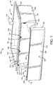
- FIGS 1-8 depict an example sink system 100 (e.g., kitchen sink system, counter sink system, etc.).
- the sink system 100 includes one or more accessories that are configured to augment capabilities of a traditional sink, such that the sink system 100 is more desirable than a traditional sink.
- the accessories are selectively repositionable within a channel that is defined between a basin of the sink and an apron of the sink.
- the accessories can be inserted into the channel, repositioned within the channel, and removed from the channel, without the apron being removed from the basin.
- the sink system 100 eliminates the need for inelegant attachments to be attached to a sink.
- the sink system 100 includes a basin 102.
- the basin 102 is configured to receive water (e.g., hot water, cold water, potable water, cleaning water, etc.), facilitate use of the water within the basin 102, and provide the water from the basin 102.
- the basin 102 includes a floor 104 that includes a drain 106 formed therein.
- the basin 102 is configured to provide water from a faucet 107 (e.g., kitchen faucet, etc.) to the drain 106, and the drain 106 is configured to pass water from the basin 102.
- a faucet 107 e.g., kitchen faucet, etc.
- the drain 106 is configured to be coupled to (e.g., attached to joined with, integrally formed with, etc.) a sink drain conduit (e.g., pipe, fitting, disposal, etc.) and to provide water from the basin 102 to the sink drain conduit.
- a sink drain conduit e.g., pipe, fitting, disposal, etc.
- the basin 102 also includes a front wall 108.
- the front wall 108 is contiguous with (e.g., connected to, sharing a border with, extending from, etc.) the floor 104.
- the basin 102 also includes a first side wall 110.
- the first side wall 110 is contiguous with the floor 104 and the front wall 108.
- the front wall 108 and the first side wall 110 are approximately (e.g., within 5% of, etc.) orthogonal.
- the basin 102 also includes a rear wall 112.
- the rear wall 112 is contiguous with the floor 104 and the first side wall 110. In some embodiments, the front wall 108 and the rear wall 112 are approximately parallel.
- the basin 102 also includes a second side wall 114.
- the second side wall 114 is contiguous with the floor 104, the front wall 108, and the rear wall 112.
- the front wall 108 and the second side wall 114 are approximately orthogonal.
- the rear wall 112 and the second side wall 114 are approximately orthogonal.
- the front wall 108, the first side wall 110, the rear wall 112, and the second side wall 114 generally define a rectangle or a square.
- the basin 102 also includes a basin rim 116.
- the basin rim 116 facilitates attachment of the basin 102 to an apron 118 (e.g., skirt, panel, etc.) and support of the basin 102 on a counter structure 120 (e.g., support, beam, chassis, etc.).
- an apron 118 e.g., skirt, panel, etc.
- a counter structure 120 e.g., support, beam, chassis, etc.
- the basin rim 116 includes a rim front side 122.
- the rim front side 122 is contiguous with the front wall 108 and extends (e.g., projects, protrudes, etc.) from the front wall 108 away from the rear wall 112.
- the rim front side 122 is coupled to (e.g., attached to, fastened to, adhered to, etc.) the apron 118.
- the rim front side 122 interfaces with the counter structure 120 (e.g., on a beam of the counter structure 120, etc.).
- the basin rim 116 also includes a rim first side 124.
- the rim first side 124 is contiguous with the first side wall 110 and the rim front side 122.
- the rim first side 124 extends from the first side wall 110 away from the second side wall 114.
- the rim first side 124 interfaces with the counter structure 120 (e.g., on a beam of the counter structure 120, etc.).
- the basin rim 116 also includes a rim rear side 126.
- the rim rear side 126 is contiguous with the rear wall 112 and the rim first side 124 and extends from the rear wall 112 away from the front wall 108.
- the rim rear side 126 is not coupled to the apron 118.
- the rim rear side 126 interfaces with the counter structure 120 (e.g., on a beam of the counter structure 120, etc.).
- the basin rim 116 also includes a rim second side 128.
- the rim second side 128 is contiguous with the second side wall 114, the rim rear side 126, and the rim front side 122.
- the rim second side 128 extends from the second side wall 114 away from the first side wall 110.
- the rim second side 128 interfaces with the counter structure 120 (e.g., on a beam of the counter structure 120, etc.).
- the basin rim 116 may be positioned at a uniform distance from a counter 130 of the counter structure 120.
- the rim front side 122 includes a stepped portion 132 and a rim shelf 134.
- the rim shelf 134 partially surrounds (e.g., borders, etc.) the stepped portion 132.
- the stepped portion 132 is extended (e.g., protruded, projected, etc.) relative to the rim shelf 134.
- the stepped portion 132 is disposed along a plane that is separated from a plane along which the rim shelf 134 is disposed, and the plane along which the stepped portion 132 is disposed is closer to the floor 104 than the plane along which the rim shelf 134 is disposed.
- the rim front side 122 includes a plurality of apertures 136 (e.g., holes, etc.) disposed in the stepped portion 132.
- the rim front side 122 may include four apertures 136 uniformly distributed along the stepped portion 132 (e.g., an adjacent pair of the apertures 136 are separated from each other by a distance that is the same as a distance separating another adjacent pair of the apertures 136, etc.).
- the apertures 136 are not through-holes. In other words, the apertures 136 do not extend entirely though the stepped portion 132.
- a top surface of the rim front side 122 e.g., a surface of the rim front side 122 that is farthest from the floor 104, etc. is uninterrupted across the apertures 136.
- the sink system 100 also includes a plurality of basin rim inserts 138 (e.g., plugs, etc.).
- Each of the apertures 136 is configured to receive one of the basin rim inserts 138.
- each of the basin rim inserts 138 may be press fit into one of the apertures 136.
- adhesive is placed into the apertures 136 prior to the basin rim inserts 138 being inserted into the apertures 136.
- the basin rim inserts 138 may be coupled to the stepped portion 132 via the adhesive and/or a friction fit between the basin rim inserts 138 and the apertures 136.
- the basin rim inserts 138 are molded into the apertures 136.
- the basin rim inserts 138 are integrally formed with the rim front side 122 (e.g., the rim front side 122 is molded around the basin rim inserts 138, etc.).
- Each of the basin rim inserts 138 has an aperture 140 (e.g., hole, etc.).
- the apertures 140 are threaded.
- Each of the apertures 140 is configured to receive a threaded fastener 142 (e.g., bolt, etc.).
- the threaded fasteners 142 are configured to be coupled to the basin rim 116 via the apertures 140 without direct interfacing between the threaded fasteners 142 and the basin rim 116. As a result, mechanical stresses and strains on the basin rim 116 may be minimized.
- Each of the threaded fasteners 142 is configured to receive a nut 144.
- the basin rim inserts 138, the threaded fasteners 142, and the nuts 144 cooperate to facilitate coupling of the apron 118 to the basin 102.
- the apron 118 includes an apron coupling wall 146.
- the apron coupling wall 146 is configured to facilitate coupling of the apron 118 to the basin 102.
- the apron coupling wall 146 includes an inner recessed portion 148 and an apron shelf 150.
- the apron shelf 150 partially surrounds the inner recessed portion 148.
- the inner recessed portion 148 is recessed relative to the apron shelf 150.
- the inner recessed portion 148 is disposed along a plane that is separated from a plane along which the apron shelf 150 is disposed, and the plane along which the inner recessed portion 148 is disposed is closer to the floor 104 than the plane along which the apron shelf 150 is disposed, when the apron 118 is coupled to the basin 102.
- the apron 118 is coupled to the basin 102, at least a portion of the apron shelf 150 is separated from the front wall 108 by the inner recessed portion 148.
- the inner recessed portion 148 is configured to receive the stepped portion 132 such that the apron shelf 150 interfaces with the rim shelf 134 when the stepped portion 132 is received within the inner recessed portion 148.
- the inner recessed portion 148 and the stepped portion 132 may both be chamfered, filleted, drafted, or otherwise shaped such that the inner recessed portion 148 is guided onto and over the stepped portion 132 when the apron 118 is lifted towards the basin 102 and subsequently coupled to the basin 102.
- the inner recessed portion 148 includes a plurality of apron slots 152 (e.g., elongated holes, slits, etc.). Each of the apron slots 152 is configured to be aligned with one of the apertures 136 when the apron 118 is coupled to the basin 102. Furthermore, each of the apron slots 152 is configured to receive one of the threaded fasteners 142.
- apron slots 152 e.g., elongated holes, slits, etc.
- the basin rim inserts 138 are first inserted into the apertures 140.
- the threaded fasteners 142 are threaded into the apertures 140.
- the apron 118 is then lifted and the apron slots 152 are aligned with the threaded fasteners 142, which are each extending from one of the apertures 136.
- the apron 118 is then translated towards the basin 102, such that the apron coupling wall 146 is located underneath and in confronting relation with the rim front side 122. This causes the stepped portion 132 to be received within the inner recessed portion 148, and for the rim shelf 134 to interface with the apron shelf 150.
- the threaded fasteners 142 are received within the apron slots 152.
- the nuts 144 are threaded onto the threaded fasteners 142 such that the apron coupling wall 146 is tightened against the rim front side 122.
- the apron slots 152 may facilitate adjustment of the apron 118 relative to the basin 102 (e.g., tilting of the apron coupling wall 146 relative to the rim front side 122, etc.) as the nuts 144 are being tightened.
- each push-nut fastener includes a base that is received within one of the apertures 140 and one of the apron slots 152.
- the base includes an aperture and at least one moveable portion.
- Each push-nut fastener also includes a bolt that is configured to be received within the apertures of the bases. As the nut is inserted into the aperture of the base, the nut contacts the moveable portion and causes the moveable portion to be displaced radially outwards, such that the moveable portion protrudes from the base when the nut is inserted into the aperture.
- the moveable portion By inserting the base into the aperture 140 and the apron slot 152, and then inserting the nut into the aperture of the base, the moveable portion can be deflected outwards (e.g., into contact with the aperture 140 and/or the apron slot 152) and provide a retention of the nut within the aperture. This retention may be transferred by the nut to the apron 118, thereby causing the apron 118 to be retained on the basin 102.
- the rim front side 122 includes a first end recess 154 and a second end recess 156.
- the first end recess 154 and the second end recess 156 are both disposed in the rim shelf 134.
- the first end recess 154 is located proximate the rim first side 124 and the second end recess 156 is located proximate the rim second side 128.
- the apron coupling wall 146 includes a first end projection 158 and a second end projection 160.
- the first end projection 158 and the second end projection 160 are both disposed in the apron shelf 150.
- the first end recess 154 is configured to receive the first end projection 158 when the rim shelf 134 interfaces with the apron shelf 150.
- the second end recess 156 is configured to receive the second end projection 160 when the rim shelf 134 interfaces with the apron shelf 150.
- the first end projection 158 may interface with the rim shelf 134 and/or the second end projection 160 may interface with the rim shelf 134.
- the first end recess 154, the second end recess 156, the first end projection 158, and the second end projection 160 cooperate to decrease a likelihood of the apron 118 being coupling to the basin 102 when the apron 118 is not desirably aligned with the basin 102.
- the first end recess 154 and the second end recess 156 are not through-holes.
- the rim first side 124 and the second end recess 156 do not extend entirely though the rim shelf 134.
- a top surface of the rim front side 122 e.g., a surface of the rim front side 122 that is farthest from the floor 104, etc.
- a top surface of the rim front side 122 is uninterrupted across the rim front side 122.
- the rim front side 122 includes a central recess 162.
- the central recess 162 is disposed in the rim shelf 134.
- the central recess 162 is located proximate a midpoint of the rim front side 122 (e.g., at an approximately equal distance from the rim first side 124 and the rim second side 128, etc.).
- the apron coupling wall 146 includes a central projection 164.
- the central projection 164 is disposed in the apron shelf 150.
- the central recess 162 is configured to receive the central projection 164 when the rim shelf 134 interfaces with the apron shelf 150.
- the central projection 164 may interface with the rim shelf 134. In this way, the central recess 162 and the central projection 164 cooperate to decrease a likelihood of the apron 118 being coupling to the basin 102 when the apron 118 is not desirably aligned with the basin 102.
- the central recess 162 is not a through-hole. In other words, the central recess 162 does not extend entirely though the rim shelf 134.
- a top surface of the rim front side 122 e.g., a surface of the rim front side 122 that is farthest from the floor 104, etc.
- the rim front side 122 includes the first end recess 154, the second end recess 156, and the central recess 162, and the apron coupling wall 146 includes the first end projection 158, the second end projection 160, and the central projection 164.
- the apron 118 also includes an apron panel wall 166.
- the apron panel wall 166 is contiguous with the apron coupling wall 146.
- the apron panel wall 166 extends from the apron coupling wall 146 away from the rim front side 122.
- the apron panel wall 166 defines an exterior surface 168 (e.g., face, etc.) and an interior surface 170 (e.g., face, etc.).
- the exterior surface 168 has a target aesthetic appearance.
- the exterior surface 168 may be textured, polished, and/or contain a design or image.
- the exterior surface 168 may provide a desired aesthetic benefit to a room within which the sink system 100 is installed.
- the sink system 100 is configured such that the apron 118 having an exterior surface 168 with a first target aesthetic appearance can be rapidly and easily interchanged with another apron 118 having an exterior surface 168 with a second target aesthetic appearance, while utilizing the same basin 102 and the same other components of the sink system 100.
- the basin 102 can remain supported by the counter structure 120 while the apron 118 coupled to the basin 102 is uncoupled from the basin 102, and a new apron 118 is coupled to the basin 102. In this way, a user can rapidly and easily provide a desired aesthetic benefit to a room within which the sink system 100 is installed.
- the sink system 100 also includes a first coupling bracket 172 and a second coupling bracket 174.
- the first coupling bracket 172 is coupled to the first side wall 110 and the interior surface 170.
- the second coupling bracket 174 is coupled to the second side wall 114 and the interior surface 170.
- the apron 118 also includes a first connector wall 176.
- the first connector wall 176 is contiguous with the apron coupling wall 146 and the apron panel wall 166.
- the first connector wall 176 extends from the apron coupling wall 146 away from the rim front side 122 and from the apron panel wall 166 towards the front wall 108.
- the apron 118 also includes an apron spanning wall 178.
- the apron spanning wall 178 is contiguous with the apron panel wall 166 and the first connector wall 176.
- the apron spanning wall 178 extends from the apron panel wall 166 towards the front wall 108 and from the first connector wall 176 away from the second side wall 114.
- the apron 118 also includes a second connector wall 180.
- the second connector wall 180 is contiguous with the apron coupling wall 146, the apron panel wall 166, and the apron spanning wall 178.
- the second connector wall 180 extends from the apron coupling wall 146 away from the rim front side 122 and from the apron panel wall 166 towards the front wall 108.
- the apron coupling wall 146 includes an outer recessed portion 182.
- the outer recessed portion 182 is partially surrounded by the apron shelf 150. Additionally, the outer recessed portion 182 is separated from the inner recessed portion 148 by the apron shelf 150.
- the central projection 164 is disposed on the apron shelf 150 between the outer recessed portion 182 and the inner recessed portion 148.
- the outer recessed portion 182 is recessed relative to the apron shelf 150.
- the outer recessed portion 182 is disposed along a plane that is separated from a plane along which the apron shelf 150 is disposed, and the plane along which the outer recessed portion 182 is disposed is closer to the floor 104 than the plane along which the apron shelf 150 is disposed, when the apron 118 is coupled to the basin 102.
- the plane along which the outer recessed portion 182 is disposed is closer to the apron spanning wall 178 than the plane along which the apron shelf 150 is disposed.
- the outer recessed portion 182 is contiguous with the exterior surface 168.
- the rim shelf 134 includes an attachment recess 184.
- the attachment recess 184 is disposed along a straight line and is configured to be aligned with the outer recessed portion 182 when the apron 118 is coupled to the basin 102.
- the central recess 162 is disposed on the rim front side 122 between the attachment recess 184 and the stepped portion 132.
- the attachment recess 184 extends through the rim shelf 134 such that a lip 186 of the rim shelf 134 is formed between the attachment recess 184 and an exterior surface 188 of the rim front side 122.
- the attachment recess 184 is recessed relative to the rim shelf 134.
- the attachment recess 184 is disposed along a plane that is separated from a plane along which the rim shelf 134 is disposed, and the plane along which the attachment recess 184 is further from the floor 104 than the plane along which the rim shelf 134 is disposed.
- the attachment recess 184 When the apron 118 is coupled to the basin 102, the attachment recess 184 is aligned with the outer recessed portion 182. Collectively, the attachment recess 184 and the outer recessed portion 182 form an apron attachment channel 190 when the apron 118 is coupled to the basin 102.
- the apron attachment channel 190 is generally L-shaped or includes at least an L-shape.
- the sink system 100 also includes an apron attachment 200.
- the apron attachment 200 is configured to be received within the apron attachment channel 190 such that the apron attachment 200 is secured within the apron attachment channel 190.
- the apron attachment 200 is also configured to be removed from the apron attachment channel 190.
- the sink system 100 is configured such that the apron attachment 200 can be received within, and removed from, the apron attachment channel 190 without uncoupling the apron 118 from the basin 102.
- the apron attachment 200 provides additional functionality to the sink system 100, thereby increasing the desirability of the sink system 100.
- the apron attachment 200 includes an apron attachment coupler 202 and an apron attachment accessory 204.
- the apron attachment coupler 202 is configured to be received within, and removed from, the apron attachment channel 190.
- the apron attachment coupler 202 includes a retainer portion 206 and a connector portion 208.
- the retainer portion 206 and the connector portion 208 are each configured to be received within the apron attachment channel 190.
- the connector portion 208 is contiguous with the retainer portion 206 and separates the apron attachment accessory 204 from the retainer portion 206.
- the connector portion 208 extends from the apron attachment channel 190 when the retainer portion 206 is received within the apron attachment channel 190.
- the retainer portion 206 is at least partially disposed within the attachment recess 184 when the apron attachment 200 is secured within the apron attachment channel 190.
- movement of the apron attachment 200 e.g., towards the exterior surface 168, away from the exterior surface 168, etc.
- the retainer portion 206 may be biased against the lip 186 and/or the rim shelf 134.
- Contact between the retainer portion 206 and the lip 186 may limit or resist movement of the retainer portion 206, and therefore movement of the connector portion 208 and the apron attachment accessory 204 (e.g., relative to the exterior surface 168, etc.).
- contact between the retainer portion 206 and rim shelf 134 may limit or resist movement of the retainer portion 206, and therefore movement of the connector portion 208 and the apron attachment accessory 204 (e.g., relative to the exterior surface 168, etc.).
- the connector portion 208 extends between the lip 186 and the outer recessed portion 182.
- the apron attachment channel 190 is configured such that the apron attachment 200 can be selectively repositioned (e.g., slid, etc.) along the apron attachment channel 190 (e.g., from a position proximate the first connector wall 176 to a position proximate the second connector wall 180, etc.).
- the retainer portion 206 is first inserted between the lip 186 and the outer recessed portion 182. Then, the apron attachment 200 is rotated and the retainer portion 206 is inserted into the attachment recess 184 and between the lip 186 and the rim shelf 134. This insertion of the outer recessed portion 182 subsequently causes an insertion of the connector portion 208 between the lip 186 and the outer recessed portion 182.
- the apron attachment accessory 204 is a towel holder (e.g., hook, ring, stud, etc.). In other embodiments, the apron attachment accessory 204 is a sponge or brush holder (e.g., container, cup, tray, etc.). In still other embodiments, the apron attachment accessory 204 is a mobile device (e.g., cell phone, smart phone, etc.) holder.
- a towel holder e.g., hook, ring, stud, etc.
- the apron attachment accessory 204 is a sponge or brush holder (e.g., container, cup, tray, etc.).
- the apron attachment accessory 204 is a mobile device (e.g., cell phone, smart phone, etc.) holder.
- a portion of the outer recessed portion 182 is disposed closer to the first connector wall 176 than the attachment recess 184 and/or a portion of the outer recessed portion 182 is disposed closer to the second connector wall 180 than the attachment recess 184.
- the apron attachment 200 can be secured to the apron attachment channel 190 by sliding the retainer portion 206 and the connector portion 208 into the apron attachment channel 190 (e.g., towards the first connector wall 176, towards the second connector wall 180, etc.).
- the basin 102 is assembled via a molding (e.g., injection molding, etc.) process that causes the basin 102 to be molded around the basin rim inserts 138 (e.g., the basin rim inserts 138 are overmolded in the basin 102, etc.).
- a molding e.g., injection molding, etc.
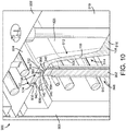
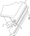
- This molding process is illustrated in Figures 9-11 . It is understood that the basin 102 may be assembled in similar ways using various other methods such as, for example, casting, machining, and additive manufacturing (e.g., 3D printing, etc.).
- the basin 102 is assembled using a molding tool 900 (e.g., injection molding tool, etc.).
- the molding tool 900 includes a body 902 that defines an internal chamber 904.
- the body 902 includes a plurality of fixed panels 906 (e.g., walls, etc.) and at least one removable panel 908 (e.g., wall, etc.).
- the fixed panels 906 and the removable panel 908 cooperate to define the internal chamber 904.
- the fixed panels 906 define an opening 910 that is contiguous with the internal chamber 904.
- the opening 910 provides access into the internal chamber 904 from a location outside of the molding tool 900.
- the removable panel 908 is selectively coupled to the fixed panels 906 around the opening 910.
- access into the internal chamber 904 via the opening 910 is prohibited (e.g., the internal chamber 904 is sealed, etc.).
- access into the internal chamber 904 via the opening 910 is facilitated (e.g., the internal chamber 904 is exposed, etc.).
- the molding tool 900 includes a male molding insert 912 (e.g., die, form, etc.) and a female molding insert 914 (e.g., die, form, etc.).
- the male molding insert 912 and the female molding insert 914 cooperate to define a mold cavity 916 (e.g., void, etc.).
- the mold cavity 916 is a volume that is substantially identical to a volume of the basin 102.
- the molding tool 900 includes at least one fluid conveyer 918 (e.g., conduit, pipe, etc.).
- the molding tool 900 is configured to provide molding material (e.g., ceramic molding material, polymeric molding material, synthetic molding material, etc.) through the body 902 and into the mold cavity 916.
- the molding tool 900 facilitates solidification of the molding material in the mold cavity 916, separation of the male molding insert 912 and the female molding insert 914, and removal of the basin 102 from the molding tool 900.
- the male molding insert 912 is configured to border top surfaces and interior surfaces of the basin 102 (e.g., relative to the floor 104, etc.) when the basin 102 is formed within the mold cavity 916.
- the female molding insert 914 is configured to border bottom surfaces and exterior surfaces of the basin 102 (e.g., relative to the floor 104, etc.) when the basin 102 is formed within the mold cavity 916.
- the male molding insert 912 is defined by a melting temperature (e.g., a temperature at which the male molding insert 912 melts, etc.) that is higher than a melting temperature (e.g., a temperature at which the molding material melts, etc.) of the molding material and a processing temperature (e.g., a temperature at which the molding material is provided into the molding tool 900, etc.) of the molding material.
- a melting temperature e.g., a temperature at which the molding material melts, etc.
- a processing temperature e.g., a temperature at which the molding material is provided into the molding tool 900, etc.
- the male molding insert 912 may be metallic (e.g., constructed from aluminum, constructed from stainless steel, etc.) and have a melting temperature that is greater than a product of 1.3 and the processing temperature of the molding material.
- the female molding insert 914 is defined by a melting temperature (e.g., a temperature at which the female molding insert 914 melts, etc.) that is higher than a melting temperature (e.g., a temperature at which the molding material melts, etc.) of the molding material and a processing temperature (e.g., a temperature at which the molding material is provided into the molding tool 900, etc.) of the molding material.
- a melting temperature e.g., a temperature at which the molding material melts, etc.
- a processing temperature e.g., a temperature at which the molding material is provided into the molding tool 900, etc.
- the female molding insert 914 may be metallic (e.g., constructed from aluminum, constructed from stainless steel, etc.) and have a melting temperature that is greater than a product of 1.3 and the processing temperature of the molding material.
- the male molding insert 912 includes a floor 919.
- the floor 919 is configured to border the floor 104 when the basin 102 is formed within the mold cavity 916.
- the floor 919 includes a drain projection.
- the drain projection extends to the female molding insert 914 such that the drain 106 is formed as the molding material solidifies around the drain projection.
- the male molding insert 912 also includes a front wall 920.
- the front wall 920 is configured to border the front wall 108 when the basin 102 is formed within the mold cavity 916.
- the front wall 920 is contiguous with the floor 919.
- the male molding insert 912 also includes a first side wall.
- the first side wall is configured to border the first side wall 110 when the basin 102 is formed within the mold cavity 916.
- the first side wall is contiguous with the floor 919 and the front wall 920.
- the male molding insert 912 also includes a rear wall 922.
- the rear wall 922 is configured to border the rear wall 112 when the basin 102 is formed within the mold cavity 916.
- the rear wall 922 is contiguous with the floor 919 and the first side wall.
- the rear wall 922 is separated from the front wall 920 by the first side wall and the floor 919.
- the male molding insert 912 also includes a second side wall.
- the second side wall is configured to border the second side wall 114 when the basin 102 is formed within the mold cavity 916.
- the second side wall is contiguous with the floor 919, the front wall 920, and the rear wall 922.
- the second side wall separates the rear wall 922 from the front wall 920
- the male molding insert 912 also includes a rim front wall 924.
- the rim front wall 924 is configured to border the rim front side 122 when the basin 102 is formed within the mold cavity 916.
- the rim front wall 924 is contiguous with the front wall 920.
- the male molding insert 912 also includes a rim first side wall.
- the rim first side wall is configured to border the rim first side 124 when the basin 102 is formed within the mold cavity 916.
- the rim first side wall is contiguous with the first side wall and the rim front wall 924.
- the male molding insert 912 also includes a rim rear side wall 926.
- the rim rear side wall 926 is configured to border the rim rear side 126 when the basin 102 is formed within the mold cavity 916.
- the rim rear side wall 926 is contiguous with the rear wall 922 and the rim first side wall.
- the rim rear side wall 926 is separated from the rim front wall 924 by the rim first side wall.
- the male molding insert 912 also includes a rim second side wall.
- the rim second side wall is configured to border the rim second side 128 when the basin 102 is formed within the mold cavity 916.
- the rim second side wall is contiguous with the second side wall, the rim front wall 924, and the rim rear side wall 926.
- the female molding insert 914 includes a floor 928.
- the floor 928 is located opposite the floor 919 when the male molding insert 912 and the female molding insert 914 are positioned within the internal chamber 904 and the mold cavity 916 is present.
- the floor 928 is configured to border the floor 104 when the basin 102 is formed within the mold cavity 916.
- the floor 928 includes a drain projection.
- the drain projection extends to the floor 919 such that the drain 106 is formed as the molding material solidifies around the drain projection.
- the floor 919 includes the drain projection and the drain projection extends to the floor 928.
- the floor 919 includes a first drain projection and the floor 928 includes a second drain projection. In these embodiments, the first drain projection and the second drain projection are aligned and in contact such that the drain 106 is formed as the molding material solidifies around the first drain projection and the second drain projection.
- the female molding insert 914 also includes a front wall 930.
- the front wall 930 is located opposite the front wall 920 when the male molding insert 912 and the female molding insert 914 are positioned within the internal chamber 904 and the mold cavity 916 is present.
- the front wall 930 is configured to border the front wall 108 when the basin 102 is formed within the mold cavity 916.
- the front wall 930 is contiguous with the floor 928.
- the female molding insert 914 also includes a first side wall.
- the first side wall of the female molding insert 914 is located opposite the first side wall of the male molding insert 912 when the male molding insert 912 and the female molding insert 914 are positioned within the internal chamber 904 and the mold cavity 916 is present.
- the first side wall is configured to border the first side wall 110 when the basin 102 is formed within the mold cavity 916.
- the first side wall is contiguous with the floor 928 and the front wall 930.
- the female molding insert 914 also includes a rear wall 932.
- the rear wall 932 is located opposite the rear wall 922 when the male molding insert 912 and the female molding insert 914 are positioned within the internal chamber 904 and the mold cavity 916 is present.
- the rear wall 932 is configured to border the rear wall 112 when the basin 102 is formed within the mold cavity 916.
- the rear wall 932 is contiguous with the floor 928 and the first side wall.
- the rear wall 932 is separated from the front wall 930 by the first side wall and the floor 928.
- the female molding insert 914 also includes a second side wall.
- the second side wall of the female molding insert 914 is located opposite the second side wall of the male molding insert 912 when the male molding insert 912 and the female molding insert 914 are positioned within the internal chamber 904 and the mold cavity 916 is present.
- the second side wall is configured to border the second side wall 114 when the basin 102 is formed within the mold cavity 916.
- the second side wall is contiguous with the floor 928, the front wall 930, and the rear wall 932. The second side wall separates the rear wall 932 from the front wall 930
- the female molding insert 914 also includes a rim front wall 934.
- the rim front wall 934 is located opposite the rim front wall 924 when the male molding insert 912 and the female molding insert 914 are positioned within the internal chamber 904 and the mold cavity 916 is present.
- the rim front wall 934 is configured to border the rim front side 122 when the basin 102 is formed within the mold cavity 916.
- the rim front wall 934 is contiguous with the front wall 930.
- the rim front wall 934 includes a stepped portion 936 and a rim shelf 938.
- the rim shelf 938 partially surrounds (e.g., borders, etc.) the stepped portion 936.
- the rim shelf 938 is extended (e.g., protruded, projected, etc.) relative to the stepped portion 936.
- the rim shelf 938 is disposed along a plane that is separated from a plane along which the stepped portion 936 is disposed, and the plane along which the rim shelf 938 is disposed is closer to the floor 928 than the plane along which the stepped portion 936 is disposed.
- the stepped portion 936 is configured to border the stepped portion 132 when the basin 102 is formed within the mold cavity 916.
- the rim shelf 938 is configured to border the rim shelf 134 when the basin 102 is formed within the mold cavity 916.
- the rim front wall 934 also includes a plurality of apertures 940 (e.g., holes, etc.) disposed in the stepped portion 936.
- the rim front wall 934 may include four apertures 940 uniformly distributed along the stepped portion 936 (e.g., an adjacent pair of the apertures 940 are separated from each other by a distance that is the same as a distance separating another adjacent pair of the apertures 940, etc.).
- Each of the apertures 940 is a through-hole. In other words, each of the apertures 940 extends entirely through the stepped portion 936.
- each of the apertures 940 is configured to receive one of the basin rim inserts 138.
- the rim front wall 934 also includes an attachment recess 942 disposed in the rim shelf 938.
- the attachment recess 942 is disposed along a straight line.
- the attachment recess 942 is configured to border the attachment recess 184 when the basin 102 is formed within the mold cavity 916.
- the rim front wall 934 also includes a central recess disposed in the rim shelf 938.
- the central recess is configured to border the central recess 162 when the basin 102 is formed within the mold cavity 916.
- the central recess may be disposed in the rim shelf 938 between the attachment recess 942 and the stepped portion 936.
- the rim front wall 934 also includes a first end recess disposed in the rim shelf 938.
- the first end recess is configured to border the first end recess 154 when the basin 102 is formed within the mold cavity 916.
- the rim front wall 934 also includes a second end recess disposed in the rim shelf 938.
- the second end recess is configured to border the second end recess 156 when the basin 102 is formed within the mold cavity 916.
- the female molding insert 914 also includes a rim first side wall.
- the rim first side wall of the female molding insert 914 is located opposite the rim first side wall of the male molding insert 912 when the male molding insert 912 and the female molding insert 914 are positioned within the internal chamber 904 and the mold cavity 916 is present.
- the rim first side wall is configured to border the rim first side 124 when the basin 102 is formed within the mold cavity 916.
- the rim first side wall is contiguous with the first side wall and the rim front wall 934.
- the female molding insert 914 also includes a rim rear side wall 944.
- the rim rear side wall 926 is located opposite the rim rear side wall 926 when the male molding insert 912 and the female molding insert 914 are positioned within the internal chamber 904 and the mold cavity 916 is present.
- the rim rear side wall 944 is configured to border the rim rear side 126 when the basin 102 is formed within the mold cavity 916.
- the rim rear side wall 944 is contiguous with the rear wall 932 and the rim first side wall.
- the rim rear side wall 944 is separated from the rim front wall 934 by the rim first side wall.
- the female molding insert 914 also includes a rim second side wall.
- the rim second side wall of the female molding insert 914 is located opposite the rim second side wall of the male molding insert 912 when the male molding insert 912 and the female molding insert 914 are positioned within the internal chamber 904 and the mold cavity 916 is present.
- the rim second side wall is configured to border the rim second side 128 when the basin 102 is formed within the mold cavity 916.
- the rim second side wall is contiguous with the second side wall, the rim front wall 934, and the rim rear side wall 944.
- the molding tool 900 also includes a plurality of insert jigs 948.
- the number of insert jigs 948 is equal to the number of basin rim inserts 138.
- the insert jigs 948 are utilized by the molding tool 900 to locate the basin rim inserts 138 within the mold cavity 916 such that the molding material forms around the basin rim inserts 138.
- the insert jigs 948 are only utilized during assembly of the basin 102 and are detached from the molding material as the basin 102 is removed from the molding tool 900.
- Each of the insert jigs 948 includes a sleeve 950 and a cylinder 952.
- the sleeve 950 is coupled to at least one of the fixed panels 906.
- the cylinder 952 is located within the sleeve 950 and is configured to be selectively repositioned within the sleeve 950.
- the cylinder 952 includes an end 954 having an end face 956.
- the end 954 is configured to be received within one of the apertures 940 and is configured to interface with the molding material.
- the end 954 is sized such that, when the end 954 is received within one of the apertures 940, a gap between the end 954 and the aperture 940 is less than 0.01 inches.
- a diameter of each of the apertures 940 may be approximately equal to 101% to 103%, inclusive, of a diameter of each of the ends 954.
- the cylinder 952 also includes a pin 958 that extends from the end face 956 (e.g., away from the end face 956).
- the pin 958 is configured to be received within the aperture 140.
- the basin rim inserts 138 Prior to providing molding material into the mold cavity 916, the basin rim inserts 138 are each coupled to one of the insert jigs 948 by aligning each of the pins 958 with one of the apertures 140 and pressing the basin rim inserts 138 toward the end faces 956.
- An interaction between the pin 958 and the basin rim insert 138 within which the pin 958 is received causes the basin rim insert 138 to be retained relative to the pin 958, and therefore relative to the female molding insert 914. This interaction may substantially preventing the basin rim inserts 138 from becoming dislodged by the molding material. As a result, a desirability of the basin 102 may be increased.
- An adhesive 960 (e.g., glue, superglue, bonding agent, etc.) is applied to the pins 958 prior to insertion of the pins 958 into the apertures 140.
- the adhesive 960 cures to secure the basin rim inserts 138 to the pins 958. Additionally, the adhesive 960 may create a seal between the pins 958 and the apertures 140. In this way, leakage of molding material between the pins 958 and the apertures 140 may be substantially minimized.
- the adhesive 960 is defined by a melting temperature (e.g., a temperature at which the adhesive 960 melts, etc.) that is higher than a melting temperature (e.g., a temperature at which the molding material melts, etc.) of the molding material and a processing temperature (e.g., a temperature at which the molding material is provided into the molding tool 900, etc.) of the molding material.
- a melting temperature e.g., a temperature at which the molding material melts, etc.
- a processing temperature e.g., a temperature at which the molding material is provided into the molding tool 900, etc.
- insertion of the pins 958 into the apertures 140 may cause deformation (e.g., stretching, etc.) of the basin rim inserts 138. This deformation may form a seal between the pins 958 and the apertures 140. In this way, leakage of molding material between the pins 958 and the apertures 140 may be substantially minimized.
- the basin rim inserts 138 are each defined by a melting temperature (e.g., a temperature at which the basin rim inserts 138 melt, etc.) that is higher than a melting temperature (e.g., a temperature at which the molding material melts, etc.) of the molding material and a processing temperature (e.g., a temperature at which the molding material is provided into the molding tool 900, etc.) of the molding material.
- a melting temperature e.g., a temperature at which the molding material melts, etc.
- a processing temperature e.g., a temperature at which the molding material is provided into the molding tool 900, etc.
- the basin rim inserts 138 may be metallic (e.g., constructed from aluminum, constructed from stainless steel, etc.) and have a melting temperature that is greater than a product of 1.3 and the processing temperature of the molding material.
- the molding material bonds to the end faces 956 around the basin rim inserts 138.
- the ends 954 are displaced relative to the mold cavity 916, thereby causing separation of the end faces 956 from the stepped portion 132.
- end recesses 962 are formed in the stepped portion 132.
- Each of the end recesses 962 is disposed over one of the basin rim inserts 138.
- the ends 954, and therefore the pins 958 are each defined by a melting temperature (e.g., a temperature at which the ends 954 melt, etc.) that is higher than a melting temperature (e.g., a temperature at which the molding material melts, etc.) of the molding material and a processing temperature (e.g., a temperature at which the molding material is provided into the molding tool 900, etc.) of the molding material.
- a melting temperature e.g., a temperature at which the molding material melts, etc.
- a processing temperature e.g., a temperature at which the molding material is provided into the molding tool 900, etc.
- the ends 954 may be metallic (e.g., constructed from aluminum, constructed from stainless steel, etc.) and have a melting temperature that is greater than a product of 1.3 and the processing temperature of the molding material.
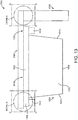
- Figure 12 illustrates an example assembly process 1200 for assembling the basin 102.
- the assembly process 1200 begins in block 1202 with determining, by a user and/or by the molding tool 900 (e.g., via sensors of the molding tool 900, etc.), if the molding tool 900 is open.
- the molding tool 900 may be open when the removable panel 908 is not coupled to the fixed panels 906 around the opening 910.
- the assembly process 1200 continues in block 1204 with opening, by the user and/or the molding tool 900, the molding tool 900 (e.g., via a user interface, etc.).
- the molding tool 900 may instruct the user to open the molding tool 900.
- the molding tool 900 is open, the male molding insert 912 is separated from the female molding insert 914, and the mold cavity 916 is not defined by the molding tool 900.
- the molding tool 900 is opened by uncoupling the removable panel 908 from the fixed panels 906 and separating the removable panel 908 from the fixed panels 906.
- the assembly process 1200 continues in block 1206 with determining, by the user and/or the molding tool, if each of the ends 954 is positioned within one of the apertures 940.
- the molding tool 900 may query the user to manually determine if each of the ends 954 is positioned within one of the apertures 940 and then, if so, to provide such an indication to the molding tool 900 (e.g., via an interactive user interface, etc.).
- the molding tool 900 may utilize sensors to determine if each of the ends 954 is positioned within one of the apertures 940.
- the assembly process 1200 continues in block 1208 with positioning, by the user and/or the molding tool 900, at least one of the ends 954 within at least one of the apertures 940.
- the molding tool 900 may query the user to manually raise the cylinders 952 such that the ends 954 are positioned within the apertures 940 and then, when completed, to provide such an indication to the molding tool 900 (e.g., via an interactive user interface, etc.).
- the molding tool 900 may raise at least one of the cylinders 952 so as to cause the cylinders 952 to be positioned within the apertures 940.
- the assembly process 1200 then continues back to block 1206 (e.g., to ensure that each of the ends 954 is positioned within one of the apertures 940, etc.).
- the assembly process 1200 continues in block 1210 with applying, by the user and/or the molding tool 900, the adhesive 960 to each of the pins 958.
- the molding tool 900 may query the user to manually apply the adhesive to each of the pins 958 and then, when completed, to provide such an indication to the molding tool 900 (e.g., via an interactive user interface, etc.).
- the assembly process 1200 continues in block 1212 with, for each of the pins 958, aligning, by the user and/or the molding tool 900, the pin 958 with an aperture 140 of a basin rim insert and pressing the basin rim insert 138 towards an end face 956 from which the pin 958 projects.
- the molding tool 900 may query the user to align each of the pins 958 with one of the apertures 140 and to manually press each of the basin rim inserts 138 towards one of the end faces 956 and then, when completed, to provide such an indication to the molding tool 900 (e.g., via an interactive user interface, etc.).
- the assembly process 1200 then continues in block 1214 with closing, by the user and/or the molding tool 900, the molding tool 900.
- the molding tool 900 may instruct the user to close the molding tool 900 (e.g., via a user interface, etc.).
- the male molding insert 912 and the female molding insert 914 cooperate to define the mold cavity 916.
- the molding tool 900 is closed by coupling the removable panel 908 to the fixed panels 906.
- the assembly process 1200 then continues in block 1216 with filling, by the user and/or the molding tool 900, the mold cavity 916 with the molding material.
- the molding tool 900 may provide the molding material into the mold cavity 916 via the fluid conveyers 918.
- the block 1216 is not performed until a target time has elapsed since the block 1210 was completed.
- the target time may be associated with a curing time of the adhesive. By adjusting the target time, curing of the adhesive 960 for each of the pins 958 may be facilitated. When the adhesive 960 is cured, a bond strength between the adhesive 960 and the pins 958 may be maximized and a bond strength between the adhesive 960 and the aperture 140 may be maximized.
- the assembly process 1200 then continues in block 1218 with opening, by the user and/or the molding tool 900, the molding tool 900.
- the molding tool 900 may instruct the user to open the molding tool 900.
- the molding tool 900 is open, the male molding insert 912 is separated from the female molding insert 914, and the mold cavity 916 is not defined by the molding tool 900.
- the molding tool 900 is opened by uncoupling the removable panel 908 from the fixed panels 906 and separating the removable panel 908 from the fixed panels 906.
- the assembly process 1200 then continues in block 1220 with separating, by the user and/or the molding tool 900, the end faces 956 from the stepped portion 132.
- the molding tool 900 may instruct the user to lower the cylinders 952, thereby causing separation of the end faces 956 from the stepped portion 132.
- the adhesive 960 is selected so as to have a bond strength (e.g., between the pin 958 and the aperture 140, etc.) that is less than a bond strength of the molding material. As a result, the basin rim inserts 138 remain embedded in the molding material when the end faces 956 are separated from the stepped portion 132.
- the end faces 956 are configured to minimize a bond strength between the end faces 956 and the molding material.
- the end faces 956 may be relatively smooth (e.g., have a relatively low surface roughness, etc.), thereby minimizing surface area to which the molding material may bond.
- the end faces 956 are coated (e.g., with lubricant, etc.) so as to mitigate bonding between the molding material and the end faces 956.
- the assembly process 1200 then concludes in block 1222 with removing, by the user and/or the molding tool 900, the basin 102 from the molding tool 900.
- the user may lift the basin 102 from the molding tool 900.
- the basin rim inserts 138 remain embedded within the basin 102.
- the assembly process 1200 may then be repeated for assembly of additional basins 102.
- FIG. 13-15 depict an example sink deck system 1300 (e.g., kitchen sink system, counter sink system, etc.).
- the sink deck system 1300 is similar to the sink system 100 described herein.
- the sink deck system 1300 incorporates a sink deck 1302 (e.g., countertop, etc.) which is coupled to a basin 1304 and an apron 1306 (e.g., skirt, panel, etc.).
- the basin 1304 is not coupled to the apron 1306.
- the sink deck 1302 supports the apron 1306 on the basin 1304.
- the sink deck system 1300 can provide the sink deck 1302 for use with the basin 1304 alone (e.g., without the apron 1306, etc.) or in combination with the apron 1306, thereby providing for simple reconfiguration for tailoring the sink deck system 1300 to a variety of target applications (e.g., dual-mount, under-mount, top-mount, etc.). Additionally, the apron 1306 can be rapidly interchanged with another apron 1306, thereby providing additional reconfiguration for tailoring the sink deck system 1300 to a variety of target applications.
- target applications e.g., dual-mount, under-mount, top-mount, etc.
- the sink deck 1302 is constructed from a first material, the basin 1304 is constructed from a second material, and the apron 1306 is constructed from a third material.
- the sink deck 1302 is constructed from a metal (e.g., stainless steel, aluminum, etc.) and the basin 1304 and the apron 1306 are both constructed from the same, or similar, non-metallic materials (e.g., ceramic materials, polymeric materials, synthetic materials, etc.).
- the sink deck 1302 is constructed from 0.25 inch thick stainless steel.
- the sink deck system 1300 includes one or more accessories that are configured to augment capabilities of a traditional sink, such that the sink deck system 1300 is more desirable than a traditional sink.
- the accessories are selectively repositionable within a channel that is defined between a basin of the sink and an apron of the sink.
- the accessories can be inserted into the channel, repositioned within the channel, and removed from the channel, without the apron being removed from the basin.
- the sink deck system 1300 eliminates the need for inelegant attachments to be attached to a sink.
- the basin 1304 is configured to receive water (e.g., hot water, cold water, potable water, cleaning water, etc.), facilitate use of the water within the basin 1304, and provide the water from the basin 1304.
- the basin 1304 includes a floor 1308 that includes a drain formed therein.
- the basin 1304 is configured to provide water from a faucet (e.g., kitchen faucet, etc.) to the drain, and the drain is configured to pass water from the basin 1304.
- the drain is configured to be coupled to (e.g., attached to, joined with, integrally formed with, etc.) a sink drain conduit (e.g., pipe, fitting, disposal, etc.) and to provide water from the basin 1304 to the sink drain conduit.
- a sink drain conduit e.g., pipe, fitting, disposal, etc.
- the basin 1304 also includes a front wall 1310.
- the front wall 1310 is contiguous with (e.g., connected to, sharing a border with, extending from, etc.) the floor 1308.
- the basin 1304 also includes a first side wall 1312.
- the first side wall 1312 is contiguous with the floor 1308 and the front wall 1310.
- the front wall 1310 and the first side wall 1312 are approximately (e.g., within 5% of, etc.) orthogonal.
- the basin 1304 also includes a rear wall 1314.
- the rear wall 1314 is contiguous with the floor 1308 and the first side wall 1312. In some embodiments, the front wall 1310 and the rear wall 1314 are approximately parallel.
- the basin 1304 also includes a second side wall.
- the second side wall is contiguous with the floor 1308, the front wall 1310, and the rear wall 1314.
- the front wall 1310 and the second side wall are approximately orthogonal.
- the rear wall 1314 and the second side wall are approximately orthogonal.
- the front wall 1310, the first side wall 1312, the rear wall 1314, and the second side wall generally define a rectangle or a square.
- the basin 1304 also includes a basin rim 1316. As is explained in more detail herein, the basin rim 1316 facilitates attachment of the basin 1304 to an apron 1306 and support of the basin 1304 on a counter structure 1318 (e.g., support, beam, chassis, etc.).
- a counter structure 1318 e.g., support, beam, chassis, etc.
- the basin rim 1316 includes a rim front side 1320.
- the rim front side 1320 is contiguous with the front wall 1310 and extends (e.g., projects, protrudes, etc.) from the front wall 1310 away from the rear wall 1314.
- the rim front side 1320 is not coupled to the apron 1306.
- the rim front side 1320 interfaces with the counter structure 1318 (e.g., on a beam of the counter structure 1318, etc.).
- the rim front side 1320 is separated from the apron 1306 (e.g., by a gap, by a spacing, etc.).
- the basin rim 1316 also includes a rim first side 1322.
- the rim first side 1322 is contiguous with the first side wall 1312 and the rim front side 1320.
- the rim first side 1322 extends from the first side wall 1312 away from the second side wall.
- the rim first side 1322 is not coupled to the apron 1306.
- the rim first side 1322 interfaces with the counter structure 1318 (e.g., on a beam of the counter structure 1318, etc.).
- the basin rim 1316 also includes a rim rear side 1324.
- the rim rear side 1324 is contiguous with the rear wall 1314 and the rim first side 1322 and extends from the rear wall 1314 away from the front wall 1310.
- the rim rear side 1324 is not coupled to the apron 1306.
- the rim rear side 1324 interfaces with the counter structure 1318 (e.g., on a beam of the counter structure 1318, etc.).
- the basin rim 1316 also includes a rim second side.
- the rim second side is contiguous with the second side wall, the rim rear side 1324, and the rim front side 1320.
- the rim second side extends from the second side wall away from the first side wall 1312.
- the rim second side is not coupled to the apron 1306.
- the rim second side interfaces with the counter structure 1318 (e.g., on a beam of the counter structure 1318, etc.).
- the basin rim 1316 may interface with a planar portion of the sink deck 1302 (e.g., such that the planar portion of the sink deck 1302 sits flush on the planar portions of the rim front side 1320, the rim first side 1322, the rim rear side 1324, and the rim second side).
- the basin rim 1316 includes a plurality of apertures 1326 (e.g., holes, etc.) disposed along the basin rim 1316.
- the apertures 1326 are configured to facilitate coupling of the basin 1304 to the sink deck 1302.
- the basin rim 1316 may include eight apertures 1326 uniformly distributed along the rim front side 1320, the rim first side 1322, the rim rear side 1324, and the rim second side.
- the apertures 1326 are through-holes. In other words, the apertures 1326 extend entirely through the basin rim 1316.
- the sink deck system 1300 also includes a plurality of basin rim inserts 1328 (e.g., plugs, etc.).
- Each of the apertures 1326 is configured to receive one of the basin rim inserts 1328.
- each of the basin rim inserts 1328 may be press fit into one of the apertures 1326.
- adhesive is placed into the apertures 1326 prior to the basin rim inserts 1328 being inserted into the apertures 1326.
- the basin rim inserts 1328 may be coupled to the basin rim 116 via the adhesive and/or a friction fit between the basin rim inserts 1328 and the apertures 1326.
- the basin rim inserts 1328 are molded into the apertures 1326.
- the basin rim inserts 1328 may be molded into the apertures 1326 in a similar process to the assembly process 1200.
- the basin rim inserts 1328 are integrally formed with the apertures 1326.
- Each of the basin rim inserts 1328 has an aperture 1330 (e.g., hole, etc.).
- the apertures 1330 are threaded.
- Each of the apertures 1330 is configured to receive a threaded fastener 1332 (e.g., bolt, etc.).
- the threaded fasteners 1332 are configured to be coupled to the basin rim 1316 via the apertures 1330 without direct interfacing between the threaded fasteners 1332 and the basin rim 1316. As a result, mechanical stresses and strains on the basin rim 1316 may be minimized.
- the sink deck 1302 includes a plurality of apertures 1334 (e.g., holes, etc.) disposed along the sink deck 1302.
- the apertures 1334 are configured to facilitate coupling of the basin 1304 to the sink deck 1302.
- the sink deck 1302 may include eight apertures 1334 uniformly distributed along the sink deck 1302.
- the sink deck 1302 may be configured such that the apertures 1334 can be aligned with the apertures 1330.
- a pattern of the apertures 1334 may match a pattern of the apertures 1330.
- the apertures 1334 are not through-holes. In other words, apertures 1334 do not extend entirely though the sink deck 1302.
- a top surface of the sink deck 1302 (e.g., a surface of the sink deck 1302 that is farthest from the floor 1308, etc.) is uninterrupted across the sink deck 1302. This may increase an aesthetic benefit of the sink deck 1302 and mitigate accumulation of grime on the sink deck 1302, thereby making the sink deck 1302 more desirable than other decks that have through-holes.
- the sink deck system 1300 also includes a plurality of sink deck inserts 1336 (e.g., plugs, etc.).
- Each of the apertures 1334 is configured to receive one of the sink deck inserts 1336.
- each of the sink deck inserts 1336 may be press fit into one of the apertures 1334.
- adhesive is placed into the apertures 1334 prior to the sink deck inserts 1336 being inserted into the apertures 1334.
- the sink deck inserts 1336 may be coupled to the sink deck 1302 via the adhesive and/or a friction fit between the sink deck inserts 1336 and the apertures 1334.
- the sink deck inserts 1336 are molded into the apertures 1334.
- the sink deck inserts 1336 may be molded into the apertures 1334 in a similar process to the assembly process 1200.
- the sink deck inserts 1336 are integrally formed with the apertures 1334.
- Each of the sink deck inserts 1336 has an aperture 1338 (e.g., hole, etc.).
- the apertures 1338 are threaded.
- Each of the apertures 1338 is configured to receive the threaded fastener 1332.
- the threaded fasteners 1332 are configured to be coupled to the sink deck 1302 via the apertures 1334 without direct interfacing between the threaded fasteners 1332 and the sink deck 1302. As a result, mechanical stresses and strains on the sink deck 1302 may be minimized.
- the basin rim inserts 1328, the fasteners 1332, and the sink deck inserts 1336 cooperate to facilitate coupling of the sink deck 1302 to the basin 1304.
- the basin rim inserts 1328 are inserted into the apertures 1326 and the sink deck inserts 1336 are inserted into the apertures 1334.
- the threaded fasteners 1332 are threaded into the apertures 1330.
- the sink deck 1302 is then lowered onto the basin rim 1316 and the apertures 1334 are aligned with the apertures 1326.
- the threaded fasteners 1332 and then threaded into the apertures 1338 and the sink deck 1302 is tightened onto the basin rim 1316.
- the sink deck 1302 includes a stepped portion 1340 and a deck shelf 1342.
- the deck shelf 1342 partially surrounds (e.g., borders, etc.) the stepped portion 1340.
- the stepped portion 1340 is extended (e.g., protruded, projected, etc.) relative to the deck shelf 1342.
- the stepped portion 1340 is disposed along a plane that is separated from a plane along which the deck shelf 1342 is disposed, and the plane along which the stepped portion 1340 is disposed is closer to the floor 1308 than the plane along which the deck shelf 1342 is disposed.
- the sink deck 1302 includes a plurality of apertures 1344 (e.g., holes, etc.) disposed in the stepped portion 1340.
- the sink deck 1302 may include four apertures 1344 uniformly distributed along the stepped portion 1340 (e.g., an adjacent pair of the apertures 1344 are separated from each other by a distance that is the same as a distance separating another adjacent pair of the apertures 1344, etc.).
- the apertures 1344 are not through-holes. In other words, the apertures 1344 do not extend entirely though the stepped portion 1340.
- a top surface of the sink deck 1302 e.g., a surface of the sink deck 1302 that is farthest from the floor 1308, etc. is uninterrupted across the apertures 1344.
- the sink deck system 1300 also includes a plurality of apron coupling inserts 1346 (e.g., plugs, etc.).
- Each of the apertures 1344 is configured to receive one of the apron coupling inserts 1346.
- each of the apron coupling inserts 1346 may be press fit into one of the apertures 1344.
- adhesive is placed into the apertures 1344 prior to the apron coupling inserts 1346 being inserted into the apertures 1344.
- the apron coupling inserts 1346 may be coupled to the stepped portion 1340 via the adhesive and/or a friction fit between the apron coupling inserts 1346 and the apertures 1344.
- the apron coupling inserts 1346 are molded into the apertures 1344.
- the apron coupling inserts 1346 are integrally formed with the apertures 1344.
- Each of the apron coupling inserts 1346 has an aperture 1348 (e.g., hole, etc.).
- the apertures 1348 are threaded.
- Each of the apertures 1348 is configured to receive a threaded fastener 1350 (e.g., bolt, etc.).
- the threaded fasteners 1350 are configured to be coupled to the sink deck 1302 via the apertures 1348 without direct interfacing between the threaded fasteners 1350 and the sink deck 1302. As a result, mechanical stresses and strains on the sink deck 1302 may be minimized.
- Each of the threaded fasteners 1350 is configured to receive a nut 1352.
- the apron coupling inserts 1346, the threaded fasteners 1350, and the nuts 1352 cooperate to facilitate coupling of the apron 1306 to the basin 1304.
- the apron 1306 includes an apron coupling wall 1354.
- the apron coupling wall 1354 is configured to facilitate coupling of the apron 1306 to the sink deck 1302.
- the apron coupling wall 1354 includes an inner recessed portion 1356 and an apron shelf 1358.
- the apron shelf 1358 partially surrounds the inner recessed portion 1356.
- the inner recessed portion 1356 is recessed relative to the apron shelf 1358.
- the inner recessed portion 1356 is disposed along a plane that is separated from a plane along which the apron shelf 1358 is disposed, and the plane along which the inner recessed portion 1356 is disposed is closer to the floor 1308 than the plane along which the apron shelf 1358 is disposed, when the apron 1306 is coupled to the sink deck 1302 and the sink deck 1302 is coupled to the basin 1304.
- the apron 1306 is coupled to the sink deck 1302 and the sink deck 1302 is coupled to the basin 1304, at least a portion of the apron shelf 1358 is separated from the front wall 1310 by the inner recessed portion 1356.
- the inner recessed portion 1356 is configured to receive the stepped portion 1340 such that the apron shelf 1358 interfaces with the deck shelf 1342 when the stepped portion 1340 is received within the inner recessed portion 1356.
- the inner recessed portion 1356 and the stepped portion 1340 may both be chamfered, filleted, drafted, or otherwise shaped such that the inner recessed portion 1356 is guided onto and over the stepped portion 1340 when the apron 1306 is lifted towards the sink deck 1302 and subsequently coupled to the sink deck 1302.
- the inner recessed portion 1356 includes a plurality of apron slots 1360 (e.g., elongated holes, slits, etc.). Each of the apron slots 1360 is configured to be aligned with one of the apertures 1344 when the apron 1306 is coupled to the sink deck 1302. Furthermore, each of the apron slots 1360 is configured to receive one of the threaded fasteners 1350.
- apron slots 1360 e.g., elongated holes, slits, etc.
- the apron coupling inserts 1346 are first inserted into the apertures 1348.
- the threaded fasteners 1350 are threaded into the apertures 1348.
- the apron 1306 is then lifted and the apron slots 1360 are aligned with the threaded fasteners 1350, which are each extending from one of the apertures 1344.
- the apron 1306 is then translated towards the basin 1304, such that the apron coupling wall 1354 is located underneath and in confronting relation with the sink deck 1302. This causes the stepped portion 1340 to be received within the inner recessed portion 1356, and for the deck shelf 1342 to interface with the apron shelf 1358.
- the threaded fasteners 1350 are received within the apron slots 1360.
- the nuts 1352 are threaded onto the threaded fasteners 1350 such that the apron coupling wall 1354 is tightened against the sink deck 1302.
- the apron slots 1360 may facilitate adjustment of the apron 1306 relative to the sink deck 1302 (e.g., tilting of the apron coupling wall 1354 relative to the sink deck 1302, etc.) as the nuts 1352 are being tightened.
- each push-nut fastener includes a base that is received within one of the apertures 1348 and one of the apron slots 1360.
- the base includes an aperture and at least one moveable portion.
- Each push-nut fastener also includes a bolt that is configured to be received within the apertures of the bases. As the nut is inserted into the aperture of the base, the nut contacts the moveable portion and causes the moveable portion to be displaced radially outwards, such that the moveable portion protrudes from the base when the nut is inserted into the aperture.
- the moveable portion By inserting the base into the aperture 1348 and the apron slot 1360, and then inserting the nut into the aperture of the base, the moveable portion can be deflected outwards (e.g., into contact with the aperture 1348 and/or the apron slot 1360) and provide a retention of the nut within the aperture. This retention may be transferred by the nut to the apron 1306, thereby causing the apron 1306 to be retained on the sink deck 1302.
- the sink deck 1302 includes a first end recess and a second end recess.
- the first end recess and the second end recess are both disposed in the deck shelf 1342.
- the first end recess is located proximate the rim first side 1322 and the second end recess is located proximate the rim second side.
- the apron coupling wall 1354 includes a first end projection and a second end projection.
- the first end projection and the second end projection are both disposed in the apron shelf 1358.
- the first end recess is configured to receive the first end projection when the deck shelf 1342 interfaces with the apron shelf 1358.
- the second end recess is configured to receive the second end projection when the deck shelf 1342 interfaces with the apron shelf 1358.
- the first end projection may interface with the deck shelf 1342 and/or the second end projection may interface with the deck shelf 1342.
- the first end recess, the second end recess, the first end projection, and the second end projection cooperate to decrease a likelihood of the apron 1306 being coupling to the sink deck 1302 when the apron 1306 is not desirably aligned with the sink deck 1302.
- the first end recess and the second end recess are not through-holes.
- the first end recess and the second end recess do not extend entirely though the deck shelf 1342.
- a top surface of the sink deck 1302 e.g., a surface of the sink deck 1302 that is farthest from the floor 1308, etc. is uninterrupted across the sink deck 1302.
- the sink deck 1302 includes a central recess.
- the central recess is disposed in the deck shelf 1342.
- the central recess is located proximate a midpoint of the sink deck 1302 (e.g., at an approximately equal distance from the rim first side 1322 and the rim second side, etc.).
- the apron coupling wall 1354 includes a central projection.
- the central projection is disposed in the apron shelf 1358.
- the central recess is configured to receive the central projection when the deck shelf 1342 interfaces with the apron shelf 1358.
- the central projection may interface with the deck shelf 1342.
- the central recess and the central projection cooperate to decrease a likelihood of the apron 1306 being coupling to the sink deck 1302 when the apron 1306 is not desirably aligned with the sink deck 1302.
- the central recess is not a through-hole. In other words, the central recess does not extend entirely though the deck shelf 1342. As a result, a top surface of the sink deck 1302 (e.g., a surface of the sink deck 1302 that is farthest from the floor 1308, etc.) is uninterrupted across the central recess.
- the sink deck 1302 includes the first end recess, the second end recess, and the central recess
- the apron coupling wall 1354 includes the first end projection, the second end projection, and the central projection.
- the apron 1306 also includes an apron panel wall 1362.
- the apron panel wall 1362 is contiguous with the apron coupling wall 1354.
- the apron panel wall 1362 extends from the apron coupling wall 1354 away from the sink deck 1302.
- the apron panel wall 1362 defines an exterior surface 1364 (e.g., face, etc.) and an interior surface 170 (e.g., face, etc.).
- the exterior surface 1364 has a target aesthetic appearance.
- the exterior surface 1364 may be textured, polished, and/or contain a design or image. In this way, the exterior surface 1364 may provide a desired aesthetic benefit to a room within which the sink deck system 1300 is installed.
- the sink deck system 1300 is configured such that the apron 1306 having an exterior surface 1364 with a first target aesthetic appearance can be rapidly and easily interchanged with another apron 1306 having an exterior surface 1364 with a second target aesthetic appearance, while utilizing the same sink deck 1302 and the same other components of the sink deck system 1300.
- the sink deck 1302 can remain supported by the counter structure 1318 while the apron 1306 coupled to the sink deck 1302 is uncoupled from the sink deck 1302, and a new apron 1306 is coupled to the sink deck 1302. In this way, a user can rapidly and easily provide a desired aesthetic benefit to a room within which the sink deck system 1300 is installed.
- the apron coupling wall 1354 includes an outer recessed portion 1366.
- the outer recessed portion 1366 is partially surrounded by the apron shelf 1358. Additionally, the outer recessed portion 1366 is separated from the inner recessed portion 1356 by the apron shelf 1358.
- the central projection is disposed on the apron shelf 1358 between the outer recessed portion 1366 and the inner recessed portion 1356.
- the outer recessed portion 1366 is recessed relative to the apron shelf 1358.
- the outer recessed portion 1366 is disposed along a plane that is separated from a plane along which the apron shelf 1358 is disposed, and the plane along which the outer recessed portion 1366 is disposed is closer to the floor 1308 than the plane along which the apron shelf 1358 is disposed, when the apron 1306 is coupled to the sink deck 1302 and the sink deck 1302 is coupled to the basin 1304.
- the plane along which the outer recessed portion 1366 is disposed is closer to the apron spanning wall 178 than the plane along which the apron shelf 1358 is disposed.
- the outer recessed portion 1366 is contiguous with the exterior surface 1364.
- the deck shelf 1342 includes an attachment recess 1368.
- the attachment recess 1368 is disposed along a straight line and is configured to be aligned with the outer recessed portion 1366 when the apron 1306 is coupled to the sink deck 1302.
- the central recess is disposed on the sink deck 1302 between the attachment recess 1368 and the stepped portion 1340.
- the attachment recess 1368 extends through the deck shelf 1342 such that a lip 1370 of the deck shelf 1342 is formed between the attachment recess 1368 and an exterior surface 1372 of the sink deck 1302.
- the attachment recess 1368 is recessed relative to the deck shelf 1342.
- the attachment recess 1368 is disposed along a plane that is separated from a plane along which the deck shelf 1342 is disposed, and the plane along which the attachment recess 1368 is further from the floor 1308 than the plane along which the deck shelf 1342 is disposed.
- the attachment recess 1368 When the apron 1306 is coupled to the sink deck 1302, the attachment recess 1368 is aligned with the outer recessed portion 1366. Collectively, the attachment recess 1368 and the outer recessed portion 1366 form an apron attachment channel 1374 when the apron 1306 is coupled to the sink deck 1302.
- the apron attachment channel 1374 is generally L-shaped or includes at least an L-shape.
- the sink deck system 1300 may also include the apron attachment 200 as described herein.
- the apron attachment 200 is configured to be received within the apron attachment channel 1374 such that the apron attachment 200 is secured within the apron attachment channel 1374.
- the apron attachment 200 is also configured to be removed from the apron attachment channel 1374.
- the sink deck system 1300 is configured such that the apron attachment 200 can be received within, and removed from, the apron attachment channel 1374 without uncoupling the apron 1306 from the sink deck 1302.
- the apron attachment 200 provides additional functionality to the sink deck system 1300, thereby increasing the desirability of the sink deck system 1300.
- the retainer portion 206 and the connector portion 208 are each configured to be received within the apron attachment channel 1374.
- the connector portion 208 extends from the apron attachment channel 1374 when the retainer portion 206 is received within the apron attachment channel 1374.
- the retainer portion 206 is at least partially disposed within the attachment recess 1368 when the apron attachment 200 is secured within the apron attachment channel 1374. As a result, movement of the apron attachment 200 (e.g., towards the exterior surface 1364, away from the exterior surface 1364, etc.) may cause the retainer portion 206 to be biased against the lip 1370 and/or the deck shelf 1342.
- Contact between the retainer portion 206 and the lip 1370 may limit or resist movement of the retainer portion 206, and therefore movement of the connector portion 208 and the apron attachment accessory 204 (e.g., relative to the exterior surface 1364, etc.).
- contact between the retainer portion 206 and deck shelf 1342 may limit or resist movement of the retainer portion 206, and therefore movement of the connector portion 208 and the apron attachment accessory 204 (e.g., relative to the exterior surface 1364, etc.).
- the connector portion 208 extends between the lip 1370 and the outer recessed portion 1366.
- the apron attachment channel 1374 is configured such that the apron attachment 200 can be selectively repositioned (e.g., slid, etc.) along the apron attachment channel 1374 (e.g., from a position proximate the first connector wall 176 to a position proximate the second connector wall 180, etc.).
- the retainer portion 206 is first inserted between the lip 1370 and the outer recessed portion 1366. Then, the apron attachment 200 is rotated and the retainer portion 206 is inserted into the attachment recess 1368 and between the lip 1370 and the deck shelf 1342. This insertion of the outer recessed portion 1366 subsequently causes an insertion of the connector portion 208 between the lip 1370 and the outer recessed portion 1366.
- Coupled and the like, as used herein, mean the joining of two components directly or indirectly to one another. Such joining may be stationary (e.g., permanent) or moveable (e.g., removable or releasable). Such joining may be achieved with the two components or the two components and any additional intermediate components being integrally formed as a single unitary body with one another, with the two components, or with the two components and any additional intermediate components being attached to one another.
- the term "or” is used in its inclusive sense (and not in its exclusive sense) so that when used, for example, to connect a list of elements, the term “or” means one, some, or all of the elements in the list.
- Conjunctive language such as the phrase "at least one of X, Y, and Z," unless specifically stated otherwise, is otherwise understood with the context as used in general to convey that an item, term, etc. may be either X, Y, Z, X and Y, X and Z, Y and Z, or X, Y, and Z (i.e., any combination of X, Y, and Z).
- Conjunctive language is not generally intended to imply that certain embodiments require at least one of X, at least one of Y, and at least one of Z to each be present, unless otherwise indicated.
- ranges of values are inclusive of their maximum values and minimum values (e.g., W to P includes W and includes P, etc.), unless otherwise indicated.
- a range of values e.g., W to P, etc.
- W to P does not necessarily require the inclusion of intermediate values within the range of values (e.g., W to P can include only W and P, etc.), unless otherwise indicated.
Landscapes
- Engineering & Computer Science (AREA)
- Health & Medical Sciences (AREA)
- Public Health (AREA)
- Mechanical Engineering (AREA)
- Environmental & Geological Engineering (AREA)
- Life Sciences & Earth Sciences (AREA)
- Hydrology & Water Resources (AREA)
- Water Supply & Treatment (AREA)
- Manufacturing & Machinery (AREA)
- Sink And Installation For Waste Water (AREA)
- Moulds For Moulding Plastics Or The Like (AREA)
- Injection Moulding Of Plastics Or The Like (AREA)
Abstract
Description
- This application claims the benefit of and priority to
U.S. Provisional Patent Application No. 62/965,534, filed January 24, 2020 U.S. Patent Application No. 17/153,514, filed January 20, 2021 - The present application relates generally to sink systems, and more particularly to sinks that incorporate various features intended to provide enhanced functionality for such sinks.
- In one embodiment, an assembly process for assembling a basin using a molding tool operable between an open position and a closed position, the molding tool having a female molding insert, a male molding insert, and an insert jig, the female molding insert and the male molding insert cooperating to define a mold cavity when the molding tool is in the closed position, the female molding insert having an aperture, the insert jig having a sleeve and a cylinder, the cylinder repositionable within the sleeve and having an end with an end face and a pin protruding from the end face, includes applying adhesive to the pin. The assembly process also includes aligning the pin with an aperture of a basin rim insert. The assembly process also includes pressing the basin rim insert towards the end face such that the pin is received within the aperture of the basin rim insert. The assembly process also includes filling the mold cavity with molding material such that the molding material encapsulates at least a portion of the basin rim insert, the molding material forming the basin within the mold cavity. The assembly process also includes placing the molding tool in the open position. The assembly process also includes removing the basin from the molding tool after placing the molding tool in the open position, the basin rim insert being at least partially encapsulated by the basin.
- In another embodiment, a sink deck assembly includes a basin, a sink deck, and an apron. The basin includes a basin rim having a first aperture. The sink deck includes a second aperture and a third aperture. The sink deck is configured to be coupled to the basin. The apron includes a slot. The apron is configured to be coupled to the sink deck. The basin, the sink deck, and the apron are configured such that the first aperture is aligned with the second aperture when the third aperture is aligned with the slot.
- In yet another embodiment, a sink deck assembly includes a sink deck, an apron, and an apron attachment. The sink deck includes a stepped portion and a deck shelf. The deck shelf is contiguous with the stepped portion. The deck shelf has an attachment recess. The apron is coupled to the sink deck. The apron includes an inner recessed portion, an apron shelf, and an outer recessed portion. The inner recessed portion is in confronting relation with the stepped portion. The apron shelf is contiguous with the inner recessed portion and in confronting relation with the deck shelf. The outer recessed portion is contiguous with the apron shelf, separated from the inner recessed portion by the apron shelf, and in confronting relation with the attachment recess. The attachment recess and the outer recessed portion collectively define an apron attachment channel. The apron attachment includes a portion that is received within the apron attachment channel.
- The details of one or more implementations are set forth in the accompanying drawings and the description below. Other features, aspects, and advantages of the disclosure will become apparent from the description, the drawings, and the claims, in which:
-
Figure 1 is a front perspective and exploded view of a sink system according to an example embodiment; -
Figure 2 is a bottom view of a basin for the sink system ofFigure 1 ; -
Figure 3 is a front view of the sink system ofFigure 1 installed in a counter structure; -
Figure 4 is a rear perspective view of a portion of the sink system ofFigure 1 ; -
Figure 5 is a cross-sectional view of the sink system shown inFigure 4 taken along plane A-A; -
Figure 6 is a rear perspective view of an apron for the sink system ofFigure 1 ; -
Figure 7 is a front perspective view of a sink system according to another example embodiment; -
Figure 8 is a cross-sectional view of the sink system shown inFigure 7 taken along plane B-B; -
Figure 9 is a perspective and cross-sectional view of a molding tool and basin according to an example embodiment; -
Figure 10 is a view of Detail A inFigure 9 ; -
Figure 11 is a view of a basin assembled by the molding tool shown inFigure 9 ; -
Figure 12 is a flowchart of an assembly process for a basin according to an example embodiment; -
Figure 13 is a side view of a sink deck system according to an example embodiment; -
Figure 14 is a view of Detail B inFigure 13 taken along plane C-C; and -
Figure 15 is a view of Detail C inFigure 13 taken along plane D-D. - It will be recognized that some or all of the Figures are schematic representations for purposes of illustration. The Figures are provided for the purpose of illustrating one or more implementations with the explicit understanding that they will not be used to limit the scope or the meaning of the claims.
- Following below are more detailed descriptions of various concepts related to, and implementations of, methods, apparatuses, and for sinks. The various concepts introduced above and discussed in greater detail below may be implemented in any of a number of ways, as the described concepts are not limited to any particular manner of implementation. Examples of specific implementations and applications are provided primarily for illustrative purposes.
- Sinks are used frequently in daily life in various environments, such as kitchens, bathrooms, laundry rooms, and the like. Depending on the intended use of the sink, it may be advantageous to utilize various accessories with the sink (e.g., sponges, wash cloths, towels, etc.). In some cases, individuals may utilize auxiliary devices, such as stick-on hooks, soap and brush containers, and removable drain stoppers in order to provide their sink with additional desired functionality. However, these auxiliary devices may have an undesirable appearance or provide an overall cluttered and inelegant look to the sink environment. Furthermore, this undesirable appearance may become increasingly undesirable as use of the auxiliary devices increases become grime and dirt can accumulate on the auxiliary devices.
- Implementations described herein are directed to sink systems that provide several functional features without requiring the use of auxiliary devices. As a result, the sink systems described herein may have a superior aesthetic appearance and enhanced functionality as compared to other sinks which do require the use of auxiliary devices.
- Some implementations described herein are directed to a sink system that includes a basin and an apron. The basin and apron are attached using threaded fasteners and define an apron attachment channel within which an apron accessory can be received when the apron is coupled to the basin. Advantageously, the apron accessory can be inserted into, removed from, and slid within the apron attachment channel while the apron remains coupled to the basin.
- Some implementations described herein are directed to a sink system that includes a basin channel within the basin. The basin channel is configured to facilitate coupling to a basin accessory. As a result, the basin accessory may be supported within the basin and suspended above a floor of the basin, by the basin channel.
- Some implementations described herein are directed to an assembly process for a basin. The assembly process utilizes a molding tool with an insert jig that is configured to facilitate at least partial encapsulation of a basin rim insert in molding material that forms the basin. The insert jig may include a pin to which the basin rim insert is adhesively attached prior to the molding tool being filled with molding material.
- Some implementations described herein are directed to a sink deck assembly that includes a basin, a sink deck, and an apron. The sink deck is coupled to the basin and the apron. Additionally, the sink deck separates the apron from the basin. As such, the sink deck system may be reconfigured between a variety of configurations, some including the sink deck and others not including the sink deck. As a result, the sink deck assembly facilitates rapid adaptation to a variety of environments such that an aesthetic and/or functional benefit of the sink deck assembly is maximized.
-
Figures 1-8 depict an example sink system 100 (e.g., kitchen sink system, counter sink system, etc.). As is explained in more detail herein, thesink system 100 includes one or more accessories that are configured to augment capabilities of a traditional sink, such that thesink system 100 is more desirable than a traditional sink. The accessories are selectively repositionable within a channel that is defined between a basin of the sink and an apron of the sink. The accessories can be inserted into the channel, repositioned within the channel, and removed from the channel, without the apron being removed from the basin. As a result, thesink system 100 eliminates the need for inelegant attachments to be attached to a sink. - The
sink system 100 includes abasin 102. As is explained in more detail herein, thebasin 102 is configured to receive water (e.g., hot water, cold water, potable water, cleaning water, etc.), facilitate use of the water within thebasin 102, and provide the water from thebasin 102. Thebasin 102 includes afloor 104 that includes adrain 106 formed therein. As is explained in more detail herein, thebasin 102 is configured to provide water from a faucet 107 (e.g., kitchen faucet, etc.) to thedrain 106, and thedrain 106 is configured to pass water from thebasin 102. Thedrain 106 is configured to be coupled to (e.g., attached to joined with, integrally formed with, etc.) a sink drain conduit (e.g., pipe, fitting, disposal, etc.) and to provide water from thebasin 102 to the sink drain conduit. - Referring to
Figure 2 , thebasin 102 also includes afront wall 108. Thefront wall 108 is contiguous with (e.g., connected to, sharing a border with, extending from, etc.) thefloor 104. Thebasin 102 also includes afirst side wall 110. Thefirst side wall 110 is contiguous with thefloor 104 and thefront wall 108. In some embodiments, thefront wall 108 and thefirst side wall 110 are approximately (e.g., within 5% of, etc.) orthogonal. - The
basin 102 also includes arear wall 112. Therear wall 112 is contiguous with thefloor 104 and thefirst side wall 110. In some embodiments, thefront wall 108 and therear wall 112 are approximately parallel. - The
basin 102 also includes asecond side wall 114. Thesecond side wall 114 is contiguous with thefloor 104, thefront wall 108, and therear wall 112. In some embodiments, thefront wall 108 and thesecond side wall 114 are approximately orthogonal. In some embodiments, therear wall 112 and thesecond side wall 114 are approximately orthogonal. In various embodiments, thefront wall 108, thefirst side wall 110, therear wall 112, and thesecond side wall 114 generally define a rectangle or a square. - The
basin 102 also includes abasin rim 116. As is explained in more detail herein, thebasin rim 116 facilitates attachment of thebasin 102 to an apron 118 (e.g., skirt, panel, etc.) and support of thebasin 102 on a counter structure 120 (e.g., support, beam, chassis, etc.). - The
basin rim 116 includes arim front side 122. Therim front side 122 is contiguous with thefront wall 108 and extends (e.g., projects, protrudes, etc.) from thefront wall 108 away from therear wall 112. In various embodiments, therim front side 122 is coupled to (e.g., attached to, fastened to, adhered to, etc.) theapron 118. In some embodiments, therim front side 122 interfaces with the counter structure 120 (e.g., on a beam of the counter structure 120, etc.). - The
basin rim 116 also includes a rimfirst side 124. The rimfirst side 124 is contiguous with thefirst side wall 110 and therim front side 122. The rimfirst side 124 extends from thefirst side wall 110 away from thesecond side wall 114. In some embodiments, the rimfirst side 124 interfaces with the counter structure 120 (e.g., on a beam of the counter structure 120, etc.). - The
basin rim 116 also includes a rimrear side 126. The rimrear side 126 is contiguous with therear wall 112 and the rimfirst side 124 and extends from therear wall 112 away from thefront wall 108. In various embodiments, the rimrear side 126 is not coupled to theapron 118. In some embodiments, the rimrear side 126 interfaces with the counter structure 120 (e.g., on a beam of the counter structure 120, etc.). - The
basin rim 116 also includes a rimsecond side 128. The rimsecond side 128 is contiguous with thesecond side wall 114, the rimrear side 126, and therim front side 122. The rimsecond side 128 extends from thesecond side wall 114 away from thefirst side wall 110. In some embodiments, the rimsecond side 128 interfaces with the counter structure 120 (e.g., on a beam of the counter structure 120, etc.). - In some embodiments, at least a portion of the
rim front side 122, at least a portion of the rimfirst side 124, at least a portion of the rimrear side 126, and at least a portion of the rimsecond side 128 are disposed along the same plane. In this way, thebasin rim 116 may be positioned at a uniform distance from acounter 130 of the counter structure 120. - As shown in
Figure 2 , therim front side 122 includes a steppedportion 132 and arim shelf 134. Therim shelf 134 partially surrounds (e.g., borders, etc.) the steppedportion 132. The steppedportion 132 is extended (e.g., protruded, projected, etc.) relative to therim shelf 134. In other words, the steppedportion 132 is disposed along a plane that is separated from a plane along which therim shelf 134 is disposed, and the plane along which the steppedportion 132 is disposed is closer to thefloor 104 than the plane along which therim shelf 134 is disposed. - The
rim front side 122 includes a plurality of apertures 136 (e.g., holes, etc.) disposed in the steppedportion 132. For example, therim front side 122 may include fourapertures 136 uniformly distributed along the stepped portion 132 (e.g., an adjacent pair of theapertures 136 are separated from each other by a distance that is the same as a distance separating another adjacent pair of theapertures 136, etc.). In various embodiments, theapertures 136 are not through-holes. In other words, theapertures 136 do not extend entirely though the steppedportion 132. As a result, a top surface of the rim front side 122 (e.g., a surface of therim front side 122 that is farthest from thefloor 104, etc.) is uninterrupted across theapertures 136. - As shown in
Figure 5 , thesink system 100 also includes a plurality of basin rim inserts 138 (e.g., plugs, etc.). Each of theapertures 136 is configured to receive one of the basin rim inserts 138. For example, each of the basin rim inserts 138 may be press fit into one of theapertures 136. In some embodiments, adhesive is placed into theapertures 136 prior to the basin rim inserts 138 being inserted into theapertures 136. In these embodiments, the basin rim inserts 138 may be coupled to the steppedportion 132 via the adhesive and/or a friction fit between the basin rim inserts 138 and theapertures 136. In some embodiments, the basin rim inserts 138 are molded into theapertures 136. In some embodiments, the basin rim inserts 138 are integrally formed with the rim front side 122 (e.g., therim front side 122 is molded around the basin rim inserts 138, etc.). - Each of the basin rim inserts 138 has an aperture 140 (e.g., hole, etc.). The
apertures 140 are threaded. Each of theapertures 140 is configured to receive a threaded fastener 142 (e.g., bolt, etc.). The threadedfasteners 142 are configured to be coupled to thebasin rim 116 via theapertures 140 without direct interfacing between the threadedfasteners 142 and thebasin rim 116. As a result, mechanical stresses and strains on thebasin rim 116 may be minimized. Each of the threadedfasteners 142 is configured to receive anut 144. As is explained in more detail herein, the basin rim inserts 138, the threadedfasteners 142, and thenuts 144 cooperate to facilitate coupling of theapron 118 to thebasin 102. - As shown in
Figure 6 , theapron 118 includes anapron coupling wall 146. As is explained in more detail herein, theapron coupling wall 146 is configured to facilitate coupling of theapron 118 to thebasin 102. Theapron coupling wall 146 includes an inner recessedportion 148 and anapron shelf 150. Theapron shelf 150 partially surrounds the inner recessedportion 148. The inner recessedportion 148 is recessed relative to theapron shelf 150. In other words, the inner recessedportion 148 is disposed along a plane that is separated from a plane along which theapron shelf 150 is disposed, and the plane along which the inner recessedportion 148 is disposed is closer to thefloor 104 than the plane along which theapron shelf 150 is disposed, when theapron 118 is coupled to thebasin 102. When theapron 118 is coupled to thebasin 102, at least a portion of theapron shelf 150 is separated from thefront wall 108 by the inner recessedportion 148. - The inner recessed
portion 148 is configured to receive the steppedportion 132 such that theapron shelf 150 interfaces with therim shelf 134 when the steppedportion 132 is received within the inner recessedportion 148. The inner recessedportion 148 and the steppedportion 132 may both be chamfered, filleted, drafted, or otherwise shaped such that the inner recessedportion 148 is guided onto and over the steppedportion 132 when theapron 118 is lifted towards thebasin 102 and subsequently coupled to thebasin 102. - The inner recessed
portion 148 includes a plurality of apron slots 152 (e.g., elongated holes, slits, etc.). Each of theapron slots 152 is configured to be aligned with one of theapertures 136 when theapron 118 is coupled to thebasin 102. Furthermore, each of theapron slots 152 is configured to receive one of the threadedfasteners 142. - To couple the
apron 118 to thebasin 102, the basin rim inserts 138 are first inserted into theapertures 140. Next, the threadedfasteners 142 are threaded into theapertures 140. Theapron 118 is then lifted and theapron slots 152 are aligned with the threadedfasteners 142, which are each extending from one of theapertures 136. Theapron 118 is then translated towards thebasin 102, such that theapron coupling wall 146 is located underneath and in confronting relation with therim front side 122. This causes the steppedportion 132 to be received within the inner recessedportion 148, and for therim shelf 134 to interface with theapron shelf 150. As a result, the threadedfasteners 142 are received within theapron slots 152. Finally, thenuts 144 are threaded onto the threadedfasteners 142 such that theapron coupling wall 146 is tightened against therim front side 122. Theapron slots 152 may facilitate adjustment of theapron 118 relative to the basin 102 (e.g., tilting of theapron coupling wall 146 relative to therim front side 122, etc.) as thenuts 144 are being tightened. - In various embodiments, the threaded
fasteners 142 and thenuts 144 are replaced with push-nut fasteners. Each push-nut fastener includes a base that is received within one of theapertures 140 and one of theapron slots 152. The base includes an aperture and at least one moveable portion. Each push-nut fastener also includes a bolt that is configured to be received within the apertures of the bases. As the nut is inserted into the aperture of the base, the nut contacts the moveable portion and causes the moveable portion to be displaced radially outwards, such that the moveable portion protrudes from the base when the nut is inserted into the aperture. By inserting the base into theaperture 140 and theapron slot 152, and then inserting the nut into the aperture of the base, the moveable portion can be deflected outwards (e.g., into contact with theaperture 140 and/or the apron slot 152) and provide a retention of the nut within the aperture. This retention may be transferred by the nut to theapron 118, thereby causing theapron 118 to be retained on thebasin 102. - In various embodiments, the
rim front side 122 includes afirst end recess 154 and asecond end recess 156. Thefirst end recess 154 and thesecond end recess 156 are both disposed in therim shelf 134. Thefirst end recess 154 is located proximate the rimfirst side 124 and thesecond end recess 156 is located proximate the rimsecond side 128. In these embodiments, theapron coupling wall 146 includes afirst end projection 158 and asecond end projection 160. Thefirst end projection 158 and thesecond end projection 160 are both disposed in theapron shelf 150. Thefirst end recess 154 is configured to receive thefirst end projection 158 when therim shelf 134 interfaces with theapron shelf 150. Similarly, thesecond end recess 156 is configured to receive thesecond end projection 160 when therim shelf 134 interfaces with theapron shelf 150. When theapron 118 is not desirably aligned with thebasin 102, thefirst end projection 158 may interface with therim shelf 134 and/or thesecond end projection 160 may interface with therim shelf 134. In this way, thefirst end recess 154, thesecond end recess 156, thefirst end projection 158, and thesecond end projection 160 cooperate to decrease a likelihood of theapron 118 being coupling to thebasin 102 when theapron 118 is not desirably aligned with thebasin 102. In various embodiments, thefirst end recess 154 and thesecond end recess 156 are not through-holes. In other words, the rimfirst side 124 and thesecond end recess 156 do not extend entirely though therim shelf 134. As a result, a top surface of the rim front side 122 (e.g., a surface of therim front side 122 that is farthest from thefloor 104, etc.) is uninterrupted across therim front side 122. - In various embodiments, the
rim front side 122 includes acentral recess 162. Thecentral recess 162 is disposed in therim shelf 134. Thecentral recess 162 is located proximate a midpoint of the rim front side 122 (e.g., at an approximately equal distance from the rimfirst side 124 and the rimsecond side 128, etc.). In these embodiments, theapron coupling wall 146 includes acentral projection 164. Thecentral projection 164 is disposed in theapron shelf 150. Thecentral recess 162 is configured to receive thecentral projection 164 when therim shelf 134 interfaces with theapron shelf 150. When theapron 118 is not desirably aligned with thebasin 102, thecentral projection 164 may interface with therim shelf 134. In this way, thecentral recess 162 and thecentral projection 164 cooperate to decrease a likelihood of theapron 118 being coupling to thebasin 102 when theapron 118 is not desirably aligned with thebasin 102. In various embodiments, thecentral recess 162 is not a through-hole. In other words, thecentral recess 162 does not extend entirely though therim shelf 134. As a result, a top surface of the rim front side 122 (e.g., a surface of therim front side 122 that is farthest from thefloor 104, etc.) is uninterrupted across thecentral recess 162. - In some embodiments, the
rim front side 122 includes thefirst end recess 154, thesecond end recess 156, and thecentral recess 162, and theapron coupling wall 146 includes thefirst end projection 158, thesecond end projection 160, and thecentral projection 164. - The
apron 118 also includes anapron panel wall 166. Theapron panel wall 166 is contiguous with theapron coupling wall 146. Theapron panel wall 166 extends from theapron coupling wall 146 away from therim front side 122. Theapron panel wall 166 defines an exterior surface 168 (e.g., face, etc.) and an interior surface 170 (e.g., face, etc.). - The
exterior surface 168 has a target aesthetic appearance. For example, theexterior surface 168 may be textured, polished, and/or contain a design or image. In this way, theexterior surface 168 may provide a desired aesthetic benefit to a room within which thesink system 100 is installed. Advantageously, thesink system 100 is configured such that theapron 118 having anexterior surface 168 with a first target aesthetic appearance can be rapidly and easily interchanged with anotherapron 118 having anexterior surface 168 with a second target aesthetic appearance, while utilizing thesame basin 102 and the same other components of thesink system 100. Additionally, thebasin 102 can remain supported by the counter structure 120 while theapron 118 coupled to thebasin 102 is uncoupled from thebasin 102, and anew apron 118 is coupled to thebasin 102. In this way, a user can rapidly and easily provide a desired aesthetic benefit to a room within which thesink system 100 is installed. - In various embodiments, the
sink system 100 also includes afirst coupling bracket 172 and asecond coupling bracket 174. Thefirst coupling bracket 172 is coupled to thefirst side wall 110 and theinterior surface 170. Similarly, thesecond coupling bracket 174 is coupled to thesecond side wall 114 and theinterior surface 170. Collectively, thefirst coupling bracket 172 and thesecond coupling bracket 174 aid in securing theapron 118 to thebasin 102. - The
apron 118 also includes afirst connector wall 176. Thefirst connector wall 176 is contiguous with theapron coupling wall 146 and theapron panel wall 166. Thefirst connector wall 176 extends from theapron coupling wall 146 away from therim front side 122 and from theapron panel wall 166 towards thefront wall 108. - The
apron 118 also includes anapron spanning wall 178. Theapron spanning wall 178 is contiguous with theapron panel wall 166 and thefirst connector wall 176. Theapron spanning wall 178 extends from theapron panel wall 166 towards thefront wall 108 and from thefirst connector wall 176 away from thesecond side wall 114. - The
apron 118 also includes asecond connector wall 180. Thesecond connector wall 180 is contiguous with theapron coupling wall 146, theapron panel wall 166, and theapron spanning wall 178. Thesecond connector wall 180 extends from theapron coupling wall 146 away from therim front side 122 and from theapron panel wall 166 towards thefront wall 108. - In various embodiments, the
apron coupling wall 146 includes an outer recessedportion 182. The outer recessedportion 182 is partially surrounded by theapron shelf 150. Additionally, the outer recessedportion 182 is separated from the inner recessedportion 148 by theapron shelf 150. In embodiments where theapron coupling wall 146 includes thecentral projection 164, thecentral projection 164 is disposed on theapron shelf 150 between the outer recessedportion 182 and the inner recessedportion 148. - The outer recessed
portion 182 is recessed relative to theapron shelf 150. In other words, the outer recessedportion 182 is disposed along a plane that is separated from a plane along which theapron shelf 150 is disposed, and the plane along which the outer recessedportion 182 is disposed is closer to thefloor 104 than the plane along which theapron shelf 150 is disposed, when theapron 118 is coupled to thebasin 102. Similarly, the plane along which the outer recessedportion 182 is disposed is closer to theapron spanning wall 178 than the plane along which theapron shelf 150 is disposed. The outer recessedportion 182 is contiguous with theexterior surface 168. - The
rim shelf 134 includes anattachment recess 184. Theattachment recess 184 is disposed along a straight line and is configured to be aligned with the outer recessedportion 182 when theapron 118 is coupled to thebasin 102. In embodiments where therim front side 122 includes thecentral recess 162, thecentral recess 162 is disposed on therim front side 122 between theattachment recess 184 and the steppedportion 132. - The
attachment recess 184 extends through therim shelf 134 such that alip 186 of therim shelf 134 is formed between theattachment recess 184 and anexterior surface 188 of therim front side 122. Theattachment recess 184 is recessed relative to therim shelf 134. In other words, theattachment recess 184 is disposed along a plane that is separated from a plane along which therim shelf 134 is disposed, and the plane along which theattachment recess 184 is further from thefloor 104 than the plane along which therim shelf 134 is disposed. - When the
apron 118 is coupled to thebasin 102, theattachment recess 184 is aligned with the outer recessedportion 182. Collectively, theattachment recess 184 and the outer recessedportion 182 form anapron attachment channel 190 when theapron 118 is coupled to thebasin 102. Theapron attachment channel 190 is generally L-shaped or includes at least an L-shape. - As shown in
Figures 2 ,3 , and6-8 , thesink system 100 also includes anapron attachment 200. Theapron attachment 200 is configured to be received within theapron attachment channel 190 such that theapron attachment 200 is secured within theapron attachment channel 190. Theapron attachment 200 is also configured to be removed from theapron attachment channel 190. Advantageously, thesink system 100 is configured such that theapron attachment 200 can be received within, and removed from, theapron attachment channel 190 without uncoupling theapron 118 from thebasin 102. As is explained in more detail herein, theapron attachment 200 provides additional functionality to thesink system 100, thereby increasing the desirability of thesink system 100. - The
apron attachment 200 includes anapron attachment coupler 202 and anapron attachment accessory 204. Theapron attachment coupler 202 is configured to be received within, and removed from, theapron attachment channel 190. - The
apron attachment coupler 202 includes aretainer portion 206 and aconnector portion 208. Theretainer portion 206 and theconnector portion 208 are each configured to be received within theapron attachment channel 190. Theconnector portion 208 is contiguous with theretainer portion 206 and separates theapron attachment accessory 204 from theretainer portion 206. Theconnector portion 208 extends from theapron attachment channel 190 when theretainer portion 206 is received within theapron attachment channel 190. - As shown in
Figure 8 , theretainer portion 206 is at least partially disposed within theattachment recess 184 when theapron attachment 200 is secured within theapron attachment channel 190. As a result, movement of the apron attachment 200 (e.g., towards theexterior surface 168, away from theexterior surface 168, etc.) may cause theretainer portion 206 to be biased against thelip 186 and/or therim shelf 134. - Contact between the
retainer portion 206 and thelip 186 may limit or resist movement of theretainer portion 206, and therefore movement of theconnector portion 208 and the apron attachment accessory 204 (e.g., relative to theexterior surface 168, etc.). Similarly, contact between theretainer portion 206 andrim shelf 134 may limit or resist movement of theretainer portion 206, and therefore movement of theconnector portion 208 and the apron attachment accessory 204 (e.g., relative to theexterior surface 168, etc.). - When the
apron attachment 200 is secured within theapron attachment channel 190, theconnector portion 208 extends between thelip 186 and the outer recessedportion 182. In various embodiments, theapron attachment channel 190 is configured such that theapron attachment 200 can be selectively repositioned (e.g., slid, etc.) along the apron attachment channel 190 (e.g., from a position proximate thefirst connector wall 176 to a position proximate thesecond connector wall 180, etc.). - To secure the
apron attachment 200 to theapron attachment channel 190, theretainer portion 206 is first inserted between thelip 186 and the outer recessedportion 182. Then, theapron attachment 200 is rotated and theretainer portion 206 is inserted into theattachment recess 184 and between thelip 186 and therim shelf 134. This insertion of the outer recessedportion 182 subsequently causes an insertion of theconnector portion 208 between thelip 186 and the outer recessedportion 182. - In various embodiments, the
apron attachment accessory 204 is a towel holder (e.g., hook, ring, stud, etc.). In other embodiments, theapron attachment accessory 204 is a sponge or brush holder (e.g., container, cup, tray, etc.). In still other embodiments, theapron attachment accessory 204 is a mobile device (e.g., cell phone, smart phone, etc.) holder. - In various embodiments, a portion of the outer recessed
portion 182 is disposed closer to thefirst connector wall 176 than theattachment recess 184 and/or a portion of the outer recessedportion 182 is disposed closer to thesecond connector wall 180 than theattachment recess 184. As a result, theapron attachment 200 can be secured to theapron attachment channel 190 by sliding theretainer portion 206 and theconnector portion 208 into the apron attachment channel 190 (e.g., towards thefirst connector wall 176, towards thesecond connector wall 180, etc.). - In various embodiments, the
basin 102 is assembled via a molding (e.g., injection molding, etc.) process that causes thebasin 102 to be molded around the basin rim inserts 138 (e.g., the basin rim inserts 138 are overmolded in thebasin 102, etc.). This molding process is illustrated inFigures 9-11 . It is understood that thebasin 102 may be assembled in similar ways using various other methods such as, for example, casting, machining, and additive manufacturing (e.g., 3D printing, etc.). - The
basin 102 is assembled using a molding tool 900 (e.g., injection molding tool, etc.). Themolding tool 900 includes a body 902 that defines aninternal chamber 904. The body 902 includes a plurality of fixed panels 906 (e.g., walls, etc.) and at least one removable panel 908 (e.g., wall, etc.). The fixedpanels 906 and theremovable panel 908 cooperate to define theinternal chamber 904. - The fixed
panels 906 define anopening 910 that is contiguous with theinternal chamber 904. In other words, theopening 910 provides access into theinternal chamber 904 from a location outside of themolding tool 900. Theremovable panel 908 is selectively coupled to the fixedpanels 906 around theopening 910. When theremovable panel 908 is coupled to the fixedpanels 906 around theopening 910, access into theinternal chamber 904 via theopening 910 is prohibited (e.g., theinternal chamber 904 is sealed, etc.). However, when theremovable panel 908 is not coupled to the fixedpanels 906 around theopening 910, access into theinternal chamber 904 via theopening 910 is facilitated (e.g., theinternal chamber 904 is exposed, etc.). - The
molding tool 900 includes a male molding insert 912 (e.g., die, form, etc.) and a female molding insert 914 (e.g., die, form, etc.). Themale molding insert 912 and thefemale molding insert 914 cooperate to define a mold cavity 916 (e.g., void, etc.). Themold cavity 916 is a volume that is substantially identical to a volume of thebasin 102. Themolding tool 900 includes at least one fluid conveyer 918 (e.g., conduit, pipe, etc.). Themolding tool 900 is configured to provide molding material (e.g., ceramic molding material, polymeric molding material, synthetic molding material, etc.) through the body 902 and into themold cavity 916. - As is explained in more detail herein, the
molding tool 900 facilitates solidification of the molding material in themold cavity 916, separation of themale molding insert 912 and thefemale molding insert 914, and removal of thebasin 102 from themolding tool 900. Themale molding insert 912 is configured to border top surfaces and interior surfaces of the basin 102 (e.g., relative to thefloor 104, etc.) when thebasin 102 is formed within themold cavity 916. Similarly, thefemale molding insert 914 is configured to border bottom surfaces and exterior surfaces of the basin 102 (e.g., relative to thefloor 104, etc.) when thebasin 102 is formed within themold cavity 916. - The
male molding insert 912 is defined by a melting temperature (e.g., a temperature at which themale molding insert 912 melts, etc.) that is higher than a melting temperature (e.g., a temperature at which the molding material melts, etc.) of the molding material and a processing temperature (e.g., a temperature at which the molding material is provided into themolding tool 900, etc.) of the molding material. For example, themale molding insert 912 may be metallic (e.g., constructed from aluminum, constructed from stainless steel, etc.) and have a melting temperature that is greater than a product of 1.3 and the processing temperature of the molding material. - Similarly, the
female molding insert 914 is defined by a melting temperature (e.g., a temperature at which thefemale molding insert 914 melts, etc.) that is higher than a melting temperature (e.g., a temperature at which the molding material melts, etc.) of the molding material and a processing temperature (e.g., a temperature at which the molding material is provided into themolding tool 900, etc.) of the molding material. For example, thefemale molding insert 914 may be metallic (e.g., constructed from aluminum, constructed from stainless steel, etc.) and have a melting temperature that is greater than a product of 1.3 and the processing temperature of the molding material. - The
male molding insert 912 includes afloor 919. Thefloor 919 is configured to border thefloor 104 when thebasin 102 is formed within themold cavity 916. In various embodiments, thefloor 919 includes a drain projection. The drain projection extends to thefemale molding insert 914 such that thedrain 106 is formed as the molding material solidifies around the drain projection. - The
male molding insert 912 also includes afront wall 920. Thefront wall 920 is configured to border thefront wall 108 when thebasin 102 is formed within themold cavity 916. Thefront wall 920 is contiguous with thefloor 919. - The
male molding insert 912 also includes a first side wall. The first side wall is configured to border thefirst side wall 110 when thebasin 102 is formed within themold cavity 916. The first side wall is contiguous with thefloor 919 and thefront wall 920. - The
male molding insert 912 also includes arear wall 922. Therear wall 922 is configured to border therear wall 112 when thebasin 102 is formed within themold cavity 916. Therear wall 922 is contiguous with thefloor 919 and the first side wall. Therear wall 922 is separated from thefront wall 920 by the first side wall and thefloor 919. - The
male molding insert 912 also includes a second side wall. The second side wall is configured to border thesecond side wall 114 when thebasin 102 is formed within themold cavity 916. The second side wall is contiguous with thefloor 919, thefront wall 920, and therear wall 922. The second side wall separates therear wall 922 from thefront wall 920 - The
male molding insert 912 also includes arim front wall 924. Therim front wall 924 is configured to border therim front side 122 when thebasin 102 is formed within themold cavity 916. Therim front wall 924 is contiguous with thefront wall 920. - The
male molding insert 912 also includes a rim first side wall. The rim first side wall is configured to border the rimfirst side 124 when thebasin 102 is formed within themold cavity 916. The rim first side wall is contiguous with the first side wall and therim front wall 924. - The
male molding insert 912 also includes a rimrear side wall 926. The rimrear side wall 926 is configured to border the rimrear side 126 when thebasin 102 is formed within themold cavity 916. The rimrear side wall 926 is contiguous with therear wall 922 and the rim first side wall. The rimrear side wall 926 is separated from therim front wall 924 by the rim first side wall. - The
male molding insert 912 also includes a rim second side wall. The rim second side wall is configured to border the rimsecond side 128 when thebasin 102 is formed within themold cavity 916. The rim second side wall is contiguous with the second side wall, therim front wall 924, and the rimrear side wall 926. - The
female molding insert 914 includes afloor 928. Thefloor 928 is located opposite thefloor 919 when themale molding insert 912 and thefemale molding insert 914 are positioned within theinternal chamber 904 and themold cavity 916 is present. Thefloor 928 is configured to border thefloor 104 when thebasin 102 is formed within themold cavity 916. In various embodiments, thefloor 928 includes a drain projection. The drain projection extends to thefloor 919 such that thedrain 106 is formed as the molding material solidifies around the drain projection. In other embodiments, thefloor 919 includes the drain projection and the drain projection extends to thefloor 928. In still other embodiments, thefloor 919 includes a first drain projection and thefloor 928 includes a second drain projection. In these embodiments, the first drain projection and the second drain projection are aligned and in contact such that thedrain 106 is formed as the molding material solidifies around the first drain projection and the second drain projection. - The
female molding insert 914 also includes afront wall 930. Thefront wall 930 is located opposite thefront wall 920 when themale molding insert 912 and thefemale molding insert 914 are positioned within theinternal chamber 904 and themold cavity 916 is present. Thefront wall 930 is configured to border thefront wall 108 when thebasin 102 is formed within themold cavity 916. Thefront wall 930 is contiguous with thefloor 928. - The
female molding insert 914 also includes a first side wall. The first side wall of thefemale molding insert 914 is located opposite the first side wall of themale molding insert 912 when themale molding insert 912 and thefemale molding insert 914 are positioned within theinternal chamber 904 and themold cavity 916 is present. The first side wall is configured to border thefirst side wall 110 when thebasin 102 is formed within themold cavity 916. The first side wall is contiguous with thefloor 928 and thefront wall 930. - The
female molding insert 914 also includes arear wall 932. Therear wall 932 is located opposite therear wall 922 when themale molding insert 912 and thefemale molding insert 914 are positioned within theinternal chamber 904 and themold cavity 916 is present. Therear wall 932 is configured to border therear wall 112 when thebasin 102 is formed within themold cavity 916. Therear wall 932 is contiguous with thefloor 928 and the first side wall. Therear wall 932 is separated from thefront wall 930 by the first side wall and thefloor 928. - The
female molding insert 914 also includes a second side wall. The second side wall of thefemale molding insert 914 is located opposite the second side wall of themale molding insert 912 when themale molding insert 912 and thefemale molding insert 914 are positioned within theinternal chamber 904 and themold cavity 916 is present. The second side wall is configured to border thesecond side wall 114 when thebasin 102 is formed within themold cavity 916. The second side wall is contiguous with thefloor 928, thefront wall 930, and therear wall 932. The second side wall separates therear wall 932 from thefront wall 930 - The
female molding insert 914 also includes arim front wall 934. Therim front wall 934 is located opposite therim front wall 924 when themale molding insert 912 and thefemale molding insert 914 are positioned within theinternal chamber 904 and themold cavity 916 is present. Therim front wall 934 is configured to border therim front side 122 when thebasin 102 is formed within themold cavity 916. Therim front wall 934 is contiguous with thefront wall 930. - The
rim front wall 934 includes a steppedportion 936 and arim shelf 938. Therim shelf 938 partially surrounds (e.g., borders, etc.) the steppedportion 936. Therim shelf 938 is extended (e.g., protruded, projected, etc.) relative to the steppedportion 936. In other words, therim shelf 938 is disposed along a plane that is separated from a plane along which the steppedportion 936 is disposed, and the plane along which therim shelf 938 is disposed is closer to thefloor 928 than the plane along which the steppedportion 936 is disposed. The steppedportion 936 is configured to border the steppedportion 132 when thebasin 102 is formed within themold cavity 916. Similarly, therim shelf 938 is configured to border therim shelf 134 when thebasin 102 is formed within themold cavity 916. - The
rim front wall 934 also includes a plurality of apertures 940 (e.g., holes, etc.) disposed in the steppedportion 936. For example, therim front wall 934 may include fourapertures 940 uniformly distributed along the stepped portion 936 (e.g., an adjacent pair of theapertures 940 are separated from each other by a distance that is the same as a distance separating another adjacent pair of theapertures 940, etc.). Each of theapertures 940 is a through-hole. In other words, each of theapertures 940 extends entirely through the steppedportion 936. As is explained in more detail herein, each of theapertures 940 is configured to receive one of the basin rim inserts 138. - The
rim front wall 934 also includes anattachment recess 942 disposed in therim shelf 938. Theattachment recess 942 is disposed along a straight line. Theattachment recess 942 is configured to border theattachment recess 184 when thebasin 102 is formed within themold cavity 916. - In various embodiments, the
rim front wall 934 also includes a central recess disposed in therim shelf 938. The central recess is configured to border thecentral recess 162 when thebasin 102 is formed within themold cavity 916. The central recess may be disposed in therim shelf 938 between theattachment recess 942 and the steppedportion 936. - In various embodiments, the
rim front wall 934 also includes a first end recess disposed in therim shelf 938. The first end recess is configured to border thefirst end recess 154 when thebasin 102 is formed within themold cavity 916. Therim front wall 934 also includes a second end recess disposed in therim shelf 938. The second end recess is configured to border thesecond end recess 156 when thebasin 102 is formed within themold cavity 916. - The
female molding insert 914 also includes a rim first side wall. The rim first side wall of thefemale molding insert 914 is located opposite the rim first side wall of themale molding insert 912 when themale molding insert 912 and thefemale molding insert 914 are positioned within theinternal chamber 904 and themold cavity 916 is present. The rim first side wall is configured to border the rimfirst side 124 when thebasin 102 is formed within themold cavity 916. The rim first side wall is contiguous with the first side wall and therim front wall 934. - The
female molding insert 914 also includes a rimrear side wall 944. The rimrear side wall 926 is located opposite the rimrear side wall 926 when themale molding insert 912 and thefemale molding insert 914 are positioned within theinternal chamber 904 and themold cavity 916 is present. The rimrear side wall 944 is configured to border the rimrear side 126 when thebasin 102 is formed within themold cavity 916. The rimrear side wall 944 is contiguous with therear wall 932 and the rim first side wall. The rimrear side wall 944 is separated from therim front wall 934 by the rim first side wall. - The
female molding insert 914 also includes a rim second side wall. The rim second side wall of thefemale molding insert 914 is located opposite the rim second side wall of themale molding insert 912 when themale molding insert 912 and thefemale molding insert 914 are positioned within theinternal chamber 904 and themold cavity 916 is present. The rim second side wall is configured to border the rimsecond side 128 when thebasin 102 is formed within themold cavity 916. The rim second side wall is contiguous with the second side wall, therim front wall 934, and the rimrear side wall 944. - The
molding tool 900 also includes a plurality of insert jigs 948. The number of insert jigs 948 is equal to the number of basin rim inserts 138. As is explained in more detail herein, the insert jigs 948 are utilized by themolding tool 900 to locate the basin rim inserts 138 within themold cavity 916 such that the molding material forms around the basin rim inserts 138. The insert jigs 948 are only utilized during assembly of thebasin 102 and are detached from the molding material as thebasin 102 is removed from themolding tool 900. - Each of the insert jigs 948 includes a
sleeve 950 and acylinder 952. Thesleeve 950 is coupled to at least one of the fixedpanels 906. Thecylinder 952 is located within thesleeve 950 and is configured to be selectively repositioned within thesleeve 950. Thecylinder 952 includes anend 954 having anend face 956. Theend 954 is configured to be received within one of theapertures 940 and is configured to interface with the molding material. Theend 954 is sized such that, when theend 954 is received within one of theapertures 940, a gap between theend 954 and theaperture 940 is less than 0.01 inches. As a result, leakage of molding material between theapertures 940 and theends 954 may be substantially minimized. For example, a diameter of each of theapertures 940 may be approximately equal to 101% to 103%, inclusive, of a diameter of each of the ends 954. - The
cylinder 952 also includes apin 958 that extends from the end face 956 (e.g., away from the end face 956). Thepin 958 is configured to be received within theaperture 140. Prior to providing molding material into themold cavity 916, the basin rim inserts 138 are each coupled to one of the insert jigs 948 by aligning each of thepins 958 with one of theapertures 140 and pressing the basin rim inserts 138 toward the end faces 956. An interaction between thepin 958 and thebasin rim insert 138 within which thepin 958 is received causes thebasin rim insert 138 to be retained relative to thepin 958, and therefore relative to thefemale molding insert 914. This interaction may substantially preventing the basin rim inserts 138 from becoming dislodged by the molding material. As a result, a desirability of thebasin 102 may be increased. - An adhesive 960 (e.g., glue, superglue, bonding agent, etc.) is applied to the
pins 958 prior to insertion of thepins 958 into theapertures 140. The adhesive 960 cures to secure the basin rim inserts 138 to thepins 958. Additionally, the adhesive 960 may create a seal between thepins 958 and theapertures 140. In this way, leakage of molding material between thepins 958 and theapertures 140 may be substantially minimized. - The adhesive 960 is defined by a melting temperature (e.g., a temperature at which the adhesive 960 melts, etc.) that is higher than a melting temperature (e.g., a temperature at which the molding material melts, etc.) of the molding material and a processing temperature (e.g., a temperature at which the molding material is provided into the
molding tool 900, etc.) of the molding material. For example, the adhesive 960 may have a melting temperature that is greater than a product of 1.3 and the processing temperature of the molding material. - In some embodiments, insertion of the
pins 958 into theapertures 140 may cause deformation (e.g., stretching, etc.) of the basin rim inserts 138. This deformation may form a seal between thepins 958 and theapertures 140. In this way, leakage of molding material between thepins 958 and theapertures 140 may be substantially minimized. - The basin rim inserts 138 are each defined by a melting temperature (e.g., a temperature at which the basin rim inserts 138 melt, etc.) that is higher than a melting temperature (e.g., a temperature at which the molding material melts, etc.) of the molding material and a processing temperature (e.g., a temperature at which the molding material is provided into the
molding tool 900, etc.) of the molding material. For example, the basin rim inserts 138 may be metallic (e.g., constructed from aluminum, constructed from stainless steel, etc.) and have a melting temperature that is greater than a product of 1.3 and the processing temperature of the molding material. - As is explained in more detail herein, as the
basin 102 is formed within themold cavity 916, the molding material bonds to the end faces 956 around the basin rim inserts 138. After the molding material solidifies within themold cavity 916, theends 954 are displaced relative to themold cavity 916, thereby causing separation of the end faces 956 from the steppedportion 132. As a result, end recesses 962 are formed in the steppedportion 132. Each of the end recesses 962 is disposed over one of the basin rim inserts 138. - The ends 954, and therefore the
pins 958, are each defined by a melting temperature (e.g., a temperature at which the ends 954 melt, etc.) that is higher than a melting temperature (e.g., a temperature at which the molding material melts, etc.) of the molding material and a processing temperature (e.g., a temperature at which the molding material is provided into themolding tool 900, etc.) of the molding material. For example, theends 954 may be metallic (e.g., constructed from aluminum, constructed from stainless steel, etc.) and have a melting temperature that is greater than a product of 1.3 and the processing temperature of the molding material. -
Figure 12 illustrates anexample assembly process 1200 for assembling thebasin 102. Theassembly process 1200 begins inblock 1202 with determining, by a user and/or by the molding tool 900 (e.g., via sensors of themolding tool 900, etc.), if themolding tool 900 is open. For example, themolding tool 900 may be open when theremovable panel 908 is not coupled to the fixedpanels 906 around theopening 910. - If in
block 1202 themolding tool 900 is closed (e.g., is not open, etc.), theassembly process 1200 continues inblock 1204 with opening, by the user and/or themolding tool 900, the molding tool 900 (e.g., via a user interface, etc.). For example, themolding tool 900 may instruct the user to open themolding tool 900. When themolding tool 900 is open, themale molding insert 912 is separated from thefemale molding insert 914, and themold cavity 916 is not defined by themolding tool 900. In some embodiments, themolding tool 900 is opened by uncoupling theremovable panel 908 from the fixedpanels 906 and separating theremovable panel 908 from the fixedpanels 906. - If in
block 1202 themolding tool 900 is open or once themolding tool 900 has been opened, theassembly process 1200 continues inblock 1206 with determining, by the user and/or the molding tool, if each of theends 954 is positioned within one of theapertures 940. For example, themolding tool 900 may query the user to manually determine if each of theends 954 is positioned within one of theapertures 940 and then, if so, to provide such an indication to the molding tool 900 (e.g., via an interactive user interface, etc.). In another example, themolding tool 900 may utilize sensors to determine if each of theends 954 is positioned within one of theapertures 940. - If in
block 1206, any of theends 954 are not positioned within one of theapertures 940, theassembly process 1200 continues inblock 1208 with positioning, by the user and/or themolding tool 900, at least one of theends 954 within at least one of theapertures 940. For example, themolding tool 900 may query the user to manually raise thecylinders 952 such that the ends 954 are positioned within theapertures 940 and then, when completed, to provide such an indication to the molding tool 900 (e.g., via an interactive user interface, etc.). In another example, themolding tool 900 may raise at least one of thecylinders 952 so as to cause thecylinders 952 to be positioned within theapertures 940. Theassembly process 1200 then continues back to block 1206 (e.g., to ensure that each of theends 954 is positioned within one of theapertures 940, etc.). - If in
block 1206, each of theends 954 is positioned within one of theapertures 940, theassembly process 1200 continues inblock 1210 with applying, by the user and/or themolding tool 900, the adhesive 960 to each of thepins 958. For example, themolding tool 900 may query the user to manually apply the adhesive to each of thepins 958 and then, when completed, to provide such an indication to the molding tool 900 (e.g., via an interactive user interface, etc.). - The
assembly process 1200 continues inblock 1212 with, for each of thepins 958, aligning, by the user and/or themolding tool 900, thepin 958 with anaperture 140 of a basin rim insert and pressing thebasin rim insert 138 towards anend face 956 from which thepin 958 projects. For example, themolding tool 900 may query the user to align each of thepins 958 with one of theapertures 140 and to manually press each of the basin rim inserts 138 towards one of the end faces 956 and then, when completed, to provide such an indication to the molding tool 900 (e.g., via an interactive user interface, etc.). - The
assembly process 1200 then continues inblock 1214 with closing, by the user and/or themolding tool 900, themolding tool 900. For example, themolding tool 900 may instruct the user to close the molding tool 900 (e.g., via a user interface, etc.). When themolding tool 900 is closed, themale molding insert 912 and thefemale molding insert 914 cooperate to define themold cavity 916. In some embodiments, themolding tool 900 is closed by coupling theremovable panel 908 to the fixedpanels 906. - The
assembly process 1200 then continues inblock 1216 with filling, by the user and/or themolding tool 900, themold cavity 916 with the molding material. For example, themolding tool 900 may provide the molding material into themold cavity 916 via thefluid conveyers 918. - In some embodiments, the
block 1216 is not performed until a target time has elapsed since theblock 1210 was completed. The target time may be associated with a curing time of the adhesive. By adjusting the target time, curing of the adhesive 960 for each of thepins 958 may be facilitated. When the adhesive 960 is cured, a bond strength between the adhesive 960 and thepins 958 may be maximized and a bond strength between the adhesive 960 and theaperture 140 may be maximized. - The
assembly process 1200 then continues inblock 1218 with opening, by the user and/or themolding tool 900, themolding tool 900. For example, themolding tool 900 may instruct the user to open themolding tool 900. When themolding tool 900 is open, themale molding insert 912 is separated from thefemale molding insert 914, and themold cavity 916 is not defined by themolding tool 900. In some embodiments, themolding tool 900 is opened by uncoupling theremovable panel 908 from the fixedpanels 906 and separating theremovable panel 908 from the fixedpanels 906. - The
assembly process 1200 then continues inblock 1220 with separating, by the user and/or themolding tool 900, the end faces 956 from the steppedportion 132. For example, themolding tool 900 may instruct the user to lower thecylinders 952, thereby causing separation of the end faces 956 from the steppedportion 132. The adhesive 960 is selected so as to have a bond strength (e.g., between thepin 958 and theaperture 140, etc.) that is less than a bond strength of the molding material. As a result, the basin rim inserts 138 remain embedded in the molding material when the end faces 956 are separated from the steppedportion 132. - In various embodiments, the end faces 956 are configured to minimize a bond strength between the end faces 956 and the molding material. For example, the end faces 956 may be relatively smooth (e.g., have a relatively low surface roughness, etc.), thereby minimizing surface area to which the molding material may bond. In some embodiments, the end faces 956 are coated (e.g., with lubricant, etc.) so as to mitigate bonding between the molding material and the end faces 956.
- The
assembly process 1200 then concludes inblock 1222 with removing, by the user and/or themolding tool 900, thebasin 102 from themolding tool 900. For example, the user may lift thebasin 102 from themolding tool 900. When thebasin 102 is removed from themolding tool 900, the basin rim inserts 138 remain embedded within thebasin 102. Theassembly process 1200 may then be repeated for assembly ofadditional basins 102. -
Figures 13-15 depict an example sink deck system 1300 (e.g., kitchen sink system, counter sink system, etc.). Thesink deck system 1300 is similar to thesink system 100 described herein. However, as is explained in more detail herein, thesink deck system 1300 incorporates a sink deck 1302 (e.g., countertop, etc.) which is coupled to abasin 1304 and an apron 1306 (e.g., skirt, panel, etc.). Unlike in thesink system 100, thebasin 1304 is not coupled to theapron 1306. Instead, thesink deck 1302 supports theapron 1306 on thebasin 1304. In this way, thesink deck system 1300 can provide thesink deck 1302 for use with thebasin 1304 alone (e.g., without theapron 1306, etc.) or in combination with theapron 1306, thereby providing for simple reconfiguration for tailoring thesink deck system 1300 to a variety of target applications (e.g., dual-mount, under-mount, top-mount, etc.). Additionally, theapron 1306 can be rapidly interchanged with anotherapron 1306, thereby providing additional reconfiguration for tailoring thesink deck system 1300 to a variety of target applications. - The
sink deck 1302 is constructed from a first material, thebasin 1304 is constructed from a second material, and theapron 1306 is constructed from a third material. In some embodiments, thesink deck 1302 is constructed from a metal (e.g., stainless steel, aluminum, etc.) and thebasin 1304 and theapron 1306 are both constructed from the same, or similar, non-metallic materials (e.g., ceramic materials, polymeric materials, synthetic materials, etc.). In some embodiments, thesink deck 1302 is constructed from 0.25 inch thick stainless steel. - In various embodiments, the
sink deck system 1300 includes one or more accessories that are configured to augment capabilities of a traditional sink, such that thesink deck system 1300 is more desirable than a traditional sink. The accessories are selectively repositionable within a channel that is defined between a basin of the sink and an apron of the sink. The accessories can be inserted into the channel, repositioned within the channel, and removed from the channel, without the apron being removed from the basin. As a result, thesink deck system 1300 eliminates the need for inelegant attachments to be attached to a sink. - As is explained in more detail herein, the
basin 1304 is configured to receive water (e.g., hot water, cold water, potable water, cleaning water, etc.), facilitate use of the water within thebasin 1304, and provide the water from thebasin 1304. Thebasin 1304 includes afloor 1308 that includes a drain formed therein. As is explained in more detail herein, thebasin 1304 is configured to provide water from a faucet (e.g., kitchen faucet, etc.) to the drain, and the drain is configured to pass water from thebasin 1304. The drain is configured to be coupled to (e.g., attached to, joined with, integrally formed with, etc.) a sink drain conduit (e.g., pipe, fitting, disposal, etc.) and to provide water from thebasin 1304 to the sink drain conduit. - The
basin 1304 also includes afront wall 1310. Thefront wall 1310 is contiguous with (e.g., connected to, sharing a border with, extending from, etc.) thefloor 1308. Thebasin 1304 also includes afirst side wall 1312. Thefirst side wall 1312 is contiguous with thefloor 1308 and thefront wall 1310. In some embodiments, thefront wall 1310 and thefirst side wall 1312 are approximately (e.g., within 5% of, etc.) orthogonal. - The
basin 1304 also includes arear wall 1314. Therear wall 1314 is contiguous with thefloor 1308 and thefirst side wall 1312. In some embodiments, thefront wall 1310 and therear wall 1314 are approximately parallel. - The
basin 1304 also includes a second side wall. The second side wall is contiguous with thefloor 1308, thefront wall 1310, and therear wall 1314. In some embodiments, thefront wall 1310 and the second side wall are approximately orthogonal. In some embodiments, therear wall 1314 and the second side wall are approximately orthogonal. In various embodiments, thefront wall 1310, thefirst side wall 1312, therear wall 1314, and the second side wall generally define a rectangle or a square. - The
basin 1304 also includes abasin rim 1316. As is explained in more detail herein, thebasin rim 1316 facilitates attachment of thebasin 1304 to anapron 1306 and support of thebasin 1304 on a counter structure 1318 (e.g., support, beam, chassis, etc.). - The
basin rim 1316 includes arim front side 1320. Therim front side 1320 is contiguous with thefront wall 1310 and extends (e.g., projects, protrudes, etc.) from thefront wall 1310 away from therear wall 1314. Therim front side 1320 is not coupled to theapron 1306. In some embodiments, therim front side 1320 interfaces with the counter structure 1318 (e.g., on a beam of thecounter structure 1318, etc.). In various embodiments, therim front side 1320 is separated from the apron 1306 (e.g., by a gap, by a spacing, etc.). - The
basin rim 1316 also includes a rimfirst side 1322. The rimfirst side 1322 is contiguous with thefirst side wall 1312 and therim front side 1320. The rimfirst side 1322 extends from thefirst side wall 1312 away from the second side wall. The rimfirst side 1322 is not coupled to theapron 1306. In some embodiments, the rimfirst side 1322 interfaces with the counter structure 1318 (e.g., on a beam of thecounter structure 1318, etc.). - The
basin rim 1316 also includes a rimrear side 1324. The rimrear side 1324 is contiguous with therear wall 1314 and the rimfirst side 1322 and extends from therear wall 1314 away from thefront wall 1310. The rimrear side 1324 is not coupled to theapron 1306. In some embodiments, the rimrear side 1324 interfaces with the counter structure 1318 (e.g., on a beam of thecounter structure 1318, etc.). - The
basin rim 1316 also includes a rim second side. The rim second side is contiguous with the second side wall, the rimrear side 1324, and therim front side 1320. The rim second side extends from the second side wall away from thefirst side wall 1312. The rim second side is not coupled to theapron 1306. In some embodiments, the rim second side interfaces with the counter structure 1318 (e.g., on a beam of thecounter structure 1318, etc.). - In some embodiments, at least a portion of the
rim front side 1320, at least a portion of the rimfirst side 1322, at least a portion of the rimrear side 1324, and at least a portion of the rim second side are disposed along the same plane. In this way, thebasin rim 1316 may interface with a planar portion of the sink deck 1302 (e.g., such that the planar portion of thesink deck 1302 sits flush on the planar portions of therim front side 1320, the rimfirst side 1322, the rimrear side 1324, and the rim second side). - As shown in
Figure 14 , thebasin rim 1316 includes a plurality of apertures 1326 (e.g., holes, etc.) disposed along thebasin rim 1316. As is explained in more detail herein, theapertures 1326 are configured to facilitate coupling of thebasin 1304 to thesink deck 1302. For example, thebasin rim 1316 may include eightapertures 1326 uniformly distributed along therim front side 1320, the rimfirst side 1322, the rimrear side 1324, and the rim second side. Unlike theapertures 136, theapertures 1326 are through-holes. In other words, theapertures 1326 extend entirely through thebasin rim 1316. - The
sink deck system 1300 also includes a plurality of basin rim inserts 1328 (e.g., plugs, etc.). Each of theapertures 1326 is configured to receive one of the basin rim inserts 1328. For example, each of the basin rim inserts 1328 may be press fit into one of theapertures 1326. In some embodiments, adhesive is placed into theapertures 1326 prior to the basin rim inserts 1328 being inserted into theapertures 1326. In these embodiments, the basin rim inserts 1328 may be coupled to thebasin rim 116 via the adhesive and/or a friction fit between the basin rim inserts 1328 and theapertures 1326. In some embodiments, the basin rim inserts 1328 are molded into theapertures 1326. For example, the basin rim inserts 1328 may be molded into theapertures 1326 in a similar process to theassembly process 1200. In some embodiments, the basin rim inserts 1328 are integrally formed with theapertures 1326. - Each of the basin rim inserts 1328 has an aperture 1330 (e.g., hole, etc.). The
apertures 1330 are threaded. Each of theapertures 1330 is configured to receive a threaded fastener 1332 (e.g., bolt, etc.). The threadedfasteners 1332 are configured to be coupled to thebasin rim 1316 via theapertures 1330 without direct interfacing between the threadedfasteners 1332 and thebasin rim 1316. As a result, mechanical stresses and strains on thebasin rim 1316 may be minimized. - The
sink deck 1302 includes a plurality of apertures 1334 (e.g., holes, etc.) disposed along thesink deck 1302. As is explained in more detail herein, theapertures 1334 are configured to facilitate coupling of thebasin 1304 to thesink deck 1302. For example, thesink deck 1302 may include eightapertures 1334 uniformly distributed along thesink deck 1302. Thesink deck 1302 may be configured such that theapertures 1334 can be aligned with theapertures 1330. For example, a pattern of theapertures 1334 may match a pattern of theapertures 1330. Unlike theapertures 1326, theapertures 1334 are not through-holes. In other words,apertures 1334 do not extend entirely though thesink deck 1302. As a result, a top surface of the sink deck 1302 (e.g., a surface of thesink deck 1302 that is farthest from thefloor 1308, etc.) is uninterrupted across thesink deck 1302. This may increase an aesthetic benefit of thesink deck 1302 and mitigate accumulation of grime on thesink deck 1302, thereby making thesink deck 1302 more desirable than other decks that have through-holes. - The
sink deck system 1300 also includes a plurality of sink deck inserts 1336 (e.g., plugs, etc.). Each of theapertures 1334 is configured to receive one of the sink deck inserts 1336. For example, each of the sink deck inserts 1336 may be press fit into one of theapertures 1334. In some embodiments, adhesive is placed into theapertures 1334 prior to the sink deck inserts 1336 being inserted into theapertures 1334. In these embodiments, the sink deck inserts 1336 may be coupled to thesink deck 1302 via the adhesive and/or a friction fit between the sink deck inserts 1336 and theapertures 1334. In some embodiments, the sink deck inserts 1336 are molded into theapertures 1334. For example, the sink deck inserts 1336 may be molded into theapertures 1334 in a similar process to theassembly process 1200. In some embodiments, the sink deck inserts 1336 are integrally formed with theapertures 1334. - Each of the sink deck inserts 1336 has an aperture 1338 (e.g., hole, etc.). The
apertures 1338 are threaded. Each of theapertures 1338 is configured to receive the threadedfastener 1332. The threadedfasteners 1332 are configured to be coupled to thesink deck 1302 via theapertures 1334 without direct interfacing between the threadedfasteners 1332 and thesink deck 1302. As a result, mechanical stresses and strains on thesink deck 1302 may be minimized. As is explained in more detail herein, the basin rim inserts 1328, thefasteners 1332, and the sink deck inserts 1336 cooperate to facilitate coupling of thesink deck 1302 to thebasin 1304. - To couple the
basin 1304 to thesink deck 1302, the basin rim inserts 1328 are inserted into theapertures 1326 and the sink deck inserts 1336 are inserted into theapertures 1334. Next, the threadedfasteners 1332 are threaded into theapertures 1330. Thesink deck 1302 is then lowered onto thebasin rim 1316 and theapertures 1334 are aligned with theapertures 1326. The threadedfasteners 1332 and then threaded into theapertures 1338 and thesink deck 1302 is tightened onto thebasin rim 1316. - As shown in
Figure 15 , thesink deck 1302 includes a steppedportion 1340 and adeck shelf 1342. Thedeck shelf 1342 partially surrounds (e.g., borders, etc.) the steppedportion 1340. The steppedportion 1340 is extended (e.g., protruded, projected, etc.) relative to thedeck shelf 1342. In other words, the steppedportion 1340 is disposed along a plane that is separated from a plane along which thedeck shelf 1342 is disposed, and the plane along which the steppedportion 1340 is disposed is closer to thefloor 1308 than the plane along which thedeck shelf 1342 is disposed. - The
sink deck 1302 includes a plurality of apertures 1344 (e.g., holes, etc.) disposed in the steppedportion 1340. For example, thesink deck 1302 may include fourapertures 1344 uniformly distributed along the stepped portion 1340 (e.g., an adjacent pair of theapertures 1344 are separated from each other by a distance that is the same as a distance separating another adjacent pair of theapertures 1344, etc.). In various embodiments, theapertures 1344 are not through-holes. In other words, theapertures 1344 do not extend entirely though the steppedportion 1340. As a result, a top surface of the sink deck 1302 (e.g., a surface of thesink deck 1302 that is farthest from thefloor 1308, etc.) is uninterrupted across theapertures 1344. - The
sink deck system 1300 also includes a plurality of apron coupling inserts 1346 (e.g., plugs, etc.). Each of theapertures 1344 is configured to receive one of the apron coupling inserts 1346. For example, each of the apron coupling inserts 1346 may be press fit into one of theapertures 1344. In some embodiments, adhesive is placed into theapertures 1344 prior to the apron coupling inserts 1346 being inserted into theapertures 1344. In these embodiments, the apron coupling inserts 1346 may be coupled to the steppedportion 1340 via the adhesive and/or a friction fit between the apron coupling inserts 1346 and theapertures 1344. In some embodiments, the apron coupling inserts 1346 are molded into theapertures 1344. In some embodiments, the apron coupling inserts 1346 are integrally formed with theapertures 1344. - Each of the apron coupling inserts 1346 has an aperture 1348 (e.g., hole, etc.). The
apertures 1348 are threaded. Each of theapertures 1348 is configured to receive a threaded fastener 1350 (e.g., bolt, etc.). The threadedfasteners 1350 are configured to be coupled to thesink deck 1302 via theapertures 1348 without direct interfacing between the threadedfasteners 1350 and thesink deck 1302. As a result, mechanical stresses and strains on thesink deck 1302 may be minimized. Each of the threadedfasteners 1350 is configured to receive anut 1352. As is explained in more detail herein, the apron coupling inserts 1346, the threadedfasteners 1350, and thenuts 1352 cooperate to facilitate coupling of theapron 1306 to thebasin 1304. - The
apron 1306 includes anapron coupling wall 1354. As is explained in more detail herein, theapron coupling wall 1354 is configured to facilitate coupling of theapron 1306 to thesink deck 1302. Theapron coupling wall 1354 includes an inner recessedportion 1356 and anapron shelf 1358. Theapron shelf 1358 partially surrounds the inner recessedportion 1356. The inner recessedportion 1356 is recessed relative to theapron shelf 1358. In other words, the inner recessedportion 1356 is disposed along a plane that is separated from a plane along which theapron shelf 1358 is disposed, and the plane along which the inner recessedportion 1356 is disposed is closer to thefloor 1308 than the plane along which theapron shelf 1358 is disposed, when theapron 1306 is coupled to thesink deck 1302 and thesink deck 1302 is coupled to thebasin 1304. When theapron 1306 is coupled to thesink deck 1302 and thesink deck 1302 is coupled to thebasin 1304, at least a portion of theapron shelf 1358 is separated from thefront wall 1310 by the inner recessedportion 1356. - The inner recessed
portion 1356 is configured to receive the steppedportion 1340 such that theapron shelf 1358 interfaces with thedeck shelf 1342 when the steppedportion 1340 is received within the inner recessedportion 1356. The inner recessedportion 1356 and the steppedportion 1340 may both be chamfered, filleted, drafted, or otherwise shaped such that the inner recessedportion 1356 is guided onto and over the steppedportion 1340 when theapron 1306 is lifted towards thesink deck 1302 and subsequently coupled to thesink deck 1302. - The inner recessed
portion 1356 includes a plurality of apron slots 1360 (e.g., elongated holes, slits, etc.). Each of theapron slots 1360 is configured to be aligned with one of theapertures 1344 when theapron 1306 is coupled to thesink deck 1302. Furthermore, each of theapron slots 1360 is configured to receive one of the threadedfasteners 1350. - To couple the
apron 1306 to thesink deck 1302, the apron coupling inserts 1346 are first inserted into theapertures 1348. Next, the threadedfasteners 1350 are threaded into theapertures 1348. Theapron 1306 is then lifted and theapron slots 1360 are aligned with the threadedfasteners 1350, which are each extending from one of theapertures 1344. Theapron 1306 is then translated towards thebasin 1304, such that theapron coupling wall 1354 is located underneath and in confronting relation with thesink deck 1302. This causes the steppedportion 1340 to be received within the inner recessedportion 1356, and for thedeck shelf 1342 to interface with theapron shelf 1358. As a result, the threadedfasteners 1350 are received within theapron slots 1360. Finally, thenuts 1352 are threaded onto the threadedfasteners 1350 such that theapron coupling wall 1354 is tightened against thesink deck 1302. Theapron slots 1360 may facilitate adjustment of theapron 1306 relative to the sink deck 1302 (e.g., tilting of theapron coupling wall 1354 relative to thesink deck 1302, etc.) as the nuts 1352 are being tightened. - In various embodiments, the threaded
fasteners 1350 and thenuts 1352 are replaced with push-nut fasteners. Each push-nut fastener includes a base that is received within one of theapertures 1348 and one of theapron slots 1360. The base includes an aperture and at least one moveable portion. Each push-nut fastener also includes a bolt that is configured to be received within the apertures of the bases. As the nut is inserted into the aperture of the base, the nut contacts the moveable portion and causes the moveable portion to be displaced radially outwards, such that the moveable portion protrudes from the base when the nut is inserted into the aperture. By inserting the base into theaperture 1348 and theapron slot 1360, and then inserting the nut into the aperture of the base, the moveable portion can be deflected outwards (e.g., into contact with theaperture 1348 and/or the apron slot 1360) and provide a retention of the nut within the aperture. This retention may be transferred by the nut to theapron 1306, thereby causing theapron 1306 to be retained on thesink deck 1302. - In various embodiments, the
sink deck 1302 includes a first end recess and a second end recess. The first end recess and the second end recess are both disposed in thedeck shelf 1342. The first end recess is located proximate the rimfirst side 1322 and the second end recess is located proximate the rim second side. In these embodiments, theapron coupling wall 1354 includes a first end projection and a second end projection. The first end projection and the second end projection are both disposed in theapron shelf 1358. The first end recess is configured to receive the first end projection when thedeck shelf 1342 interfaces with theapron shelf 1358. Similarly, the second end recess is configured to receive the second end projection when thedeck shelf 1342 interfaces with theapron shelf 1358. When theapron 1306 is not desirably aligned with thesink deck 1302, the first end projection may interface with thedeck shelf 1342 and/or the second end projection may interface with thedeck shelf 1342. In this way, the first end recess, the second end recess, the first end projection, and the second end projection cooperate to decrease a likelihood of theapron 1306 being coupling to thesink deck 1302 when theapron 1306 is not desirably aligned with thesink deck 1302. In various embodiments, the first end recess and the second end recess are not through-holes. In other words, the first end recess and the second end recess do not extend entirely though thedeck shelf 1342. As a result, a top surface of the sink deck 1302 (e.g., a surface of thesink deck 1302 that is farthest from thefloor 1308, etc.) is uninterrupted across thesink deck 1302. - In various embodiments, the
sink deck 1302 includes a central recess. The central recess is disposed in thedeck shelf 1342. The central recess is located proximate a midpoint of the sink deck 1302 (e.g., at an approximately equal distance from the rimfirst side 1322 and the rim second side, etc.). In these embodiments, theapron coupling wall 1354 includes a central projection. The central projection is disposed in theapron shelf 1358. The central recess is configured to receive the central projection when thedeck shelf 1342 interfaces with theapron shelf 1358. When theapron 1306 is not desirably aligned with thesink deck 1302, the central projection may interface with thedeck shelf 1342. In this way, the central recess and the central projection cooperate to decrease a likelihood of theapron 1306 being coupling to thesink deck 1302 when theapron 1306 is not desirably aligned with thesink deck 1302. In various embodiments, the central recess is not a through-hole. In other words, the central recess does not extend entirely though thedeck shelf 1342. As a result, a top surface of the sink deck 1302 (e.g., a surface of thesink deck 1302 that is farthest from thefloor 1308, etc.) is uninterrupted across the central recess. - In some embodiments, the
sink deck 1302 includes the first end recess, the second end recess, and the central recess, and theapron coupling wall 1354 includes the first end projection, the second end projection, and the central projection. - The
apron 1306 also includes anapron panel wall 1362. Theapron panel wall 1362 is contiguous with theapron coupling wall 1354. Theapron panel wall 1362 extends from theapron coupling wall 1354 away from thesink deck 1302. Theapron panel wall 1362 defines an exterior surface 1364 (e.g., face, etc.) and an interior surface 170 (e.g., face, etc.). - The
exterior surface 1364 has a target aesthetic appearance. For example, theexterior surface 1364 may be textured, polished, and/or contain a design or image. In this way, theexterior surface 1364 may provide a desired aesthetic benefit to a room within which thesink deck system 1300 is installed. Advantageously, thesink deck system 1300 is configured such that theapron 1306 having anexterior surface 1364 with a first target aesthetic appearance can be rapidly and easily interchanged with anotherapron 1306 having anexterior surface 1364 with a second target aesthetic appearance, while utilizing thesame sink deck 1302 and the same other components of thesink deck system 1300. Additionally, thesink deck 1302 can remain supported by thecounter structure 1318 while theapron 1306 coupled to thesink deck 1302 is uncoupled from thesink deck 1302, and anew apron 1306 is coupled to thesink deck 1302. In this way, a user can rapidly and easily provide a desired aesthetic benefit to a room within which thesink deck system 1300 is installed. - In various embodiments, the
apron coupling wall 1354 includes an outer recessedportion 1366. The outer recessedportion 1366 is partially surrounded by theapron shelf 1358. Additionally, the outer recessedportion 1366 is separated from the inner recessedportion 1356 by theapron shelf 1358. In embodiments where theapron coupling wall 1354 includes the central projection, the central projection is disposed on theapron shelf 1358 between the outer recessedportion 1366 and the inner recessedportion 1356. - The outer recessed
portion 1366 is recessed relative to theapron shelf 1358. In other words, the outer recessedportion 1366 is disposed along a plane that is separated from a plane along which theapron shelf 1358 is disposed, and the plane along which the outer recessedportion 1366 is disposed is closer to thefloor 1308 than the plane along which theapron shelf 1358 is disposed, when theapron 1306 is coupled to thesink deck 1302 and thesink deck 1302 is coupled to thebasin 1304. Similarly, the plane along which the outer recessedportion 1366 is disposed is closer to theapron spanning wall 178 than the plane along which theapron shelf 1358 is disposed. The outer recessedportion 1366 is contiguous with theexterior surface 1364. - The
deck shelf 1342 includes anattachment recess 1368. Theattachment recess 1368 is disposed along a straight line and is configured to be aligned with the outer recessedportion 1366 when theapron 1306 is coupled to thesink deck 1302. In embodiments where thesink deck 1302 includes the central recess, the central recess is disposed on thesink deck 1302 between theattachment recess 1368 and the steppedportion 1340. - The
attachment recess 1368 extends through thedeck shelf 1342 such that alip 1370 of thedeck shelf 1342 is formed between theattachment recess 1368 and anexterior surface 1372 of thesink deck 1302. Theattachment recess 1368 is recessed relative to thedeck shelf 1342. In other words, theattachment recess 1368 is disposed along a plane that is separated from a plane along which thedeck shelf 1342 is disposed, and the plane along which theattachment recess 1368 is further from thefloor 1308 than the plane along which thedeck shelf 1342 is disposed. - When the
apron 1306 is coupled to thesink deck 1302, theattachment recess 1368 is aligned with the outer recessedportion 1366. Collectively, theattachment recess 1368 and the outer recessedportion 1366 form anapron attachment channel 1374 when theapron 1306 is coupled to thesink deck 1302. Theapron attachment channel 1374 is generally L-shaped or includes at least an L-shape. - The
sink deck system 1300 may also include theapron attachment 200 as described herein. Theapron attachment 200 is configured to be received within theapron attachment channel 1374 such that theapron attachment 200 is secured within theapron attachment channel 1374. Theapron attachment 200 is also configured to be removed from theapron attachment channel 1374. Advantageously, thesink deck system 1300 is configured such that theapron attachment 200 can be received within, and removed from, theapron attachment channel 1374 without uncoupling theapron 1306 from thesink deck 1302. As is explained in more detail herein, theapron attachment 200 provides additional functionality to thesink deck system 1300, thereby increasing the desirability of thesink deck system 1300. - The
retainer portion 206 and theconnector portion 208 are each configured to be received within theapron attachment channel 1374. Theconnector portion 208 extends from theapron attachment channel 1374 when theretainer portion 206 is received within theapron attachment channel 1374. - The
retainer portion 206 is at least partially disposed within theattachment recess 1368 when theapron attachment 200 is secured within theapron attachment channel 1374. As a result, movement of the apron attachment 200 (e.g., towards theexterior surface 1364, away from theexterior surface 1364, etc.) may cause theretainer portion 206 to be biased against thelip 1370 and/or thedeck shelf 1342. - Contact between the
retainer portion 206 and thelip 1370 may limit or resist movement of theretainer portion 206, and therefore movement of theconnector portion 208 and the apron attachment accessory 204 (e.g., relative to theexterior surface 1364, etc.). Similarly, contact between theretainer portion 206 anddeck shelf 1342 may limit or resist movement of theretainer portion 206, and therefore movement of theconnector portion 208 and the apron attachment accessory 204 (e.g., relative to theexterior surface 1364, etc.). - When the
apron attachment 200 is secured within theapron attachment channel 1374, theconnector portion 208 extends between thelip 1370 and the outer recessedportion 1366. In various embodiments, theapron attachment channel 1374 is configured such that theapron attachment 200 can be selectively repositioned (e.g., slid, etc.) along the apron attachment channel 1374 (e.g., from a position proximate thefirst connector wall 176 to a position proximate thesecond connector wall 180, etc.). - To secure the
apron attachment 200 to theapron attachment channel 1374, theretainer portion 206 is first inserted between thelip 1370 and the outer recessedportion 1366. Then, theapron attachment 200 is rotated and theretainer portion 206 is inserted into theattachment recess 1368 and between thelip 1370 and thedeck shelf 1342. This insertion of the outer recessedportion 1366 subsequently causes an insertion of theconnector portion 208 between thelip 1370 and the outer recessedportion 1366. - While this specification contains many specific implementation details, these should not be construed as limitations on the scope of what may be claimed but rather as descriptions of features specific to particular implementations. Certain features described in this specification in the context of separate implementations can also be implemented in combination in a single implementation. Conversely, various features described in the context of a single implementation can also be implemented in multiple implementations separately or in any suitable subcombination. Moreover, although features may be described as acting in certain combinations and even initially claimed as such, one or more features from a claimed combination can, in some cases, be excised from the combination, and the claimed combination may be directed to a subcombination or variation of a subcombination.
- As utilized herein, the term "approximately," "generally," and similar terms are intended to have a broad meaning in harmony with the common and accepted usage by those of ordinary skill in the art to which the subject matter of this disclosure pertains. It should be understood by those of skill in the art who review this disclosure that these terms are intended to allow a description of certain features described and claimed without restricting the scope of these features to the precise numerical ranges provided. Accordingly, these terms should be interpreted as indicating that insubstantial or inconsequential modifications or alterations of the subject matter described and claimed are considered to be within the scope of the present disclosure as recited in the appended claims.
- The term "coupled" and the like, as used herein, mean the joining of two components directly or indirectly to one another. Such joining may be stationary (e.g., permanent) or moveable (e.g., removable or releasable). Such joining may be achieved with the two components or the two components and any additional intermediate components being integrally formed as a single unitary body with one another, with the two components, or with the two components and any additional intermediate components being attached to one another.
- It is important to note that the construction and arrangement of the system shown in the various example implementations is illustrative only and not restrictive in character. All changes and modifications that come within the spirit and/or scope of the described implementations are desired to be protected. It should be understood that some features may not be necessary, and implementations lacking the various features may be contemplated as within the scope of the application, the scope being defined by the claims that follow. When the language "a portion" is used, the item can include a portion and/or the entire item unless specifically stated to the contrary.
- Also, the term "or" is used in its inclusive sense (and not in its exclusive sense) so that when used, for example, to connect a list of elements, the term "or" means one, some, or all of the elements in the list. Conjunctive language such as the phrase "at least one of X, Y, and Z," unless specifically stated otherwise, is otherwise understood with the context as used in general to convey that an item, term, etc. may be either X, Y, Z, X and Y, X and Z, Y and Z, or X, Y, and Z (i.e., any combination of X, Y, and Z). Thus, such conjunctive language is not generally intended to imply that certain embodiments require at least one of X, at least one of Y, and at least one of Z to each be present, unless otherwise indicated.
- Additionally, the use of ranges of values (e.g., W to P, etc.) herein are inclusive of their maximum values and minimum values (e.g., W to P includes W and includes P, etc.), unless otherwise indicated. Furthermore, a range of values (e.g., W to P, etc.) does not necessarily require the inclusion of intermediate values within the range of values (e.g., W to P can include only W and P, etc.), unless otherwise indicated.
Claims (15)
- An assembly process for assembling a basin using a molding tool operable between an open position and a closed position, the molding tool having a female molding insert, a male molding insert, and an insert jig, the female molding insert and the male molding insert cooperating to define a mold cavity when the molding tool is in the closed position, the female molding insert having an aperture, the insert jig having a sleeve and a cylinder, the cylinder repositionable within the sleeve and having an end with an end face and a pin protruding from the end face, the assembly process comprising:applying adhesive to the pin;aligning the pin with an aperture of a basin rim insert;pressing the basin rim insert towards the end face such that the pin is received within the aperture of the basin rim insert;filling the mold cavity with molding material such that the molding material encapsulates at least a portion of the basin rim insert, the molding material forming the basin within the mold cavity;placing the molding tool in the open position; andremoving the basin from the molding tool after placing the molding tool in the open position, the basin rim insert being at least partially encapsulated by the basin.
- The assembly process of Claim 1, further comprising inserting at least a portion of the basin rim insert through the aperture of the female molding insert prior to filing the mold cavity with the molding material and after pressing the basin rim insert towards the end face;
wherein the molding material bonds to the end face around the basin rim insert as the molding material forms the basin within the mold cavity. - The assembly process of Claim 2, wherein:the female molding insert comprises:a front wall; anda rim front wall that is contiguous with the front wall;the male molding insert comprises:a front wall; anda rim front wall that is contiguous with the front wall;the rim front wall of the female molding insert is in confronting relation with the rim front wall of the male insert when the mold cavity is filled with the molding material;the front wall of the female molding insert is in confronting relation with the front wall of the male molding insert when the mold cavity is filled with the molding material;a basin rim of the basin is formed between the rim front wall of the female molding insert and the rim front wall of the male insert when the mold cavity is filled with the molding material; andthe aperture of the female molding insert is disposed in the rim front wall of the female molding insert.
- The assembly process of Claim 2 or Claim 3, further comprising separating the molding material from the end face around the basin rim insert after filling the mold cavity with the molding material.
- The assembly process of Claim 4, further comprising: separating the pin from the basin rim insert after filling the mold cavity with the molding material; and/or repositioning the cylinder within the sleeve and away from the basin rim insert after filling the mold cavity with the molding material, wherein the molding material is separated from the end face around the basin rim insert as the cylinder is repositioned within the sleeve and away from the basin rim insert.
- The assembly process of any one of the preceding claims, wherein the basin rim insert is at least partially encapsulated by the basin within a basin rim of the basin and/or wherein the basin rim insert is metallic.
- The assembly process of any one of the preceding claims, further comprising lowering the cylinder relative to the female molding insert after filling the mold cavity with the molding material;
wherein the lowering the cylinder relative to the female molding insert causes the pin to be removed from the aperture of the basin rim insert. - A sink deck assembly comprising:a basin comprising a basin rim having a first aperture;a sink deck comprising a second aperture and a third aperture, the sink deck configured to be coupled to the basin; andan apron comprising a slot, the apron configured to be coupled to the sink deck;wherein the basin, the sink deck, and the apron are configured such that the first aperture is aligned with the second aperture when the third aperture is aligned with the slot.
- The sink deck assembly of Claim 8, further comprising:a first fastener configured to threadably engage the first aperture and the second aperture to couple the sink deck to the basin;an apron coupling insert disposed within the third aperture, the apron coupling insert having a fourth aperture; anda second fastener configured to engage the slot and the fourth aperture to couple the apron to the sink deck.
- The sink deck assembly of Claim 8 or Claim 9, wherein the basin is separated from the apron by the sink deck when the sink deck is coupled to the basin and the sink deck is coupled to the apron.
- The sink deck assembly of Claim 8, Claim 9 or Claim 10, wherein:the basin is constructed from a first material;the apron is constructed from a second material;the sink deck is constructed from a third material; andthe third material is different from at least one of the first material or the second material;optionally wherein:the first material is non-metallic;the second material is non-metallic; andthe third material is metallic.
- The sink deck assembly of any one of claims 8 to 11, wherein:the sink deck comprises:a stepped portion; anda deck shelf contiguous with the stepped portion, the deck shelf having an attachment recess; andthe apron comprises:an inner recessed portion that is in confronting relation with the stepped portion when the apron is coupled to the sink deck;an apron shelf that is contiguous with the inner recessed portion and in confronting relation with the deck shelf when the apron is coupled to the sink deck; andan outer recessed portion that is contiguous with the apron shelf and separated from the inner recessed portion by the apron shelf and in confronting relation with the attachment recess when the apron is coupled to the sink deck; and
the attachment recess and the outer recessed portion collectively define an apron attachment channel when the apron is coupled to the sink deck;optionally wherein:the slot is disposed in the inner recessed portion; andthe third aperture is disposed in the stepped portion. - A sink deck assembly comprising:a sink deck comprising:a stepped portion; anda deck shelf contiguous with the stepped portion, the deck shelf having an attachment recess;an apron coupled to the sink deck, the apron comprising:an inner recessed portion in confronting relation with the stepped portion;an apron shelf contiguous with the inner recessed portion and in confronting relation with the deck shelf; andan outer recessed portion contiguous with the apron shelf, separated from the inner recessed portion by the apron shelf, and in confronting relation with the attachment recess, the attachment recess and the outer recessed portion collectively defining an apron attachment channel; andan apron attachment comprising a portion that is received within the apron attachment channel.
- The sink deck assembly of Claim 13, further comprising a fastener that couples the apron to the sink deck;
wherein the inner recessed portion comprises a slot;
wherein the deck shelf comprises an aperture;
wherein the fastener is received within the aperture and coupled to the deck shelf via the aperture; and
wherein the fastener is received within the slot and coupled to the apron via the slot. - The sink deck assembly of Claim 13 or Claim 14, wherein the portion is selectively repositionable with, and selectively removable from, the apron attachment channel and/or further comprising a basin coupled to the sink deck, the basin separated from the apron by the sink deck.
Priority Applications (1)
| Application Number | Priority Date | Filing Date | Title |
|---|---|---|---|
| EP22152801.1A EP4008516A1 (en) | 2020-01-24 | 2021-01-22 | Sink systems |
Applications Claiming Priority (2)
| Application Number | Priority Date | Filing Date | Title |
|---|---|---|---|
| US202062965534P | 2020-01-24 | 2020-01-24 | |
| US17/153,514 US12123182B2 (en) | 2020-01-24 | 2021-01-20 | Method of manufacturing a sink system |
Related Child Applications (2)
| Application Number | Title | Priority Date | Filing Date |
|---|---|---|---|
| EP22152801.1A Division EP4008516A1 (en) | 2020-01-24 | 2021-01-22 | Sink systems |
| EP22152801.1A Division-Into EP4008516A1 (en) | 2020-01-24 | 2021-01-22 | Sink systems |
Publications (3)
| Publication Number | Publication Date |
|---|---|
| EP3854563A2 true EP3854563A2 (en) | 2021-07-28 |
| EP3854563A3 EP3854563A3 (en) | 2021-10-20 |
| EP3854563B1 EP3854563B1 (en) | 2023-09-27 |
Family
ID=74215767
Family Applications (2)
| Application Number | Title | Priority Date | Filing Date |
|---|---|---|---|
| EP22152801.1A Pending EP4008516A1 (en) | 2020-01-24 | 2021-01-22 | Sink systems |
| EP21153093.6A Active EP3854563B1 (en) | 2020-01-24 | 2021-01-22 | Assembly process for assembling a basin |
Family Applications Before (1)
| Application Number | Title | Priority Date | Filing Date |
|---|---|---|---|
| EP22152801.1A Pending EP4008516A1 (en) | 2020-01-24 | 2021-01-22 | Sink systems |
Country Status (3)
| Country | Link |
|---|---|
| US (2) | US12123182B2 (en) |
| EP (2) | EP4008516A1 (en) |
| CN (1) | CN113175035B (en) |
Families Citing this family (5)
| Publication number | Priority date | Publication date | Assignee | Title |
|---|---|---|---|---|
| USD934400S1 (en) * | 2019-09-05 | 2021-10-26 | Kohler Co. | Sink |
| US11457736B2 (en) * | 2019-10-16 | 2022-10-04 | Kohler Co. | Vessel sink and method of installing same |
| USD952808S1 (en) * | 2020-01-24 | 2022-05-24 | Kohler Co. | Sink |
| USD941970S1 (en) | 2020-08-05 | 2022-01-25 | Kohler Co. | Sink |
| USD1110481S1 (en) * | 2022-12-22 | 2026-01-27 | Kohler Co. | Sink |
Family Cites Families (362)
| Publication number | Priority date | Publication date | Assignee | Title |
|---|---|---|---|---|
| US208094A (en) | 1878-09-17 | Improvement in soap-dishes for iron sinks | ||
| US526390A (en) | 1894-09-25 | Attachment for washstands | ||
| US594962A (en) | 1897-12-07 | Soap-dish | ||
| US792498A (en) | 1904-07-06 | 1905-06-13 | George W Carr | Cuspidor. |
| US832309A (en) | 1905-08-12 | 1906-10-02 | John S Frey | Sink-strainer. |
| US948954A (en) | 1908-11-16 | 1910-02-08 | James E Cody | Sink-strainer. |
| US915057A (en) | 1908-11-30 | 1909-03-09 | Louis J Monahan | Washbasin attachment. |
| US958857A (en) | 1909-07-14 | 1910-05-24 | Mollie A Dennis | Dish-drainer. |
| US981448A (en) | 1909-11-05 | 1911-01-10 | Harry Matthews | Sink-strainer. |
| US1006994A (en) | 1911-07-13 | 1911-10-24 | Barnes Mfg Company | Pump-shelf. |
| US1225308A (en) | 1916-01-26 | 1917-05-08 | Julius L Born | Garbage-receptacle for sinks. |
| US1408812A (en) | 1921-12-08 | 1922-03-07 | John J Leighton | Splash guard for sinks |
| US1587693A (en) | 1924-07-26 | 1926-06-08 | Edith M Beland | Attachment for sinks |
| US1579374A (en) | 1925-06-16 | 1926-04-06 | John J Leighton | Splash guard for sinks |
| US1576607A (en) | 1925-11-21 | 1926-03-16 | William S Hasskarl | Domestic sink cabinet |
| US1618032A (en) | 1926-10-30 | 1927-02-15 | Wilkes Frederic | Splashboard |
| US1880733A (en) | 1930-05-05 | 1932-10-04 | Bolhuis Frank | Cupboard unit construction |
| US2045965A (en) | 1932-03-05 | 1936-06-30 | Milton J Rosen | Sink attachment |
| US1986935A (en) | 1934-04-23 | 1935-01-08 | Levine Max | Pot support for kitchen sinks |
| US2005459A (en) | 1934-12-19 | 1935-06-18 | Ida L Finn | Strainer for sinks |
| US2098374A (en) | 1936-01-08 | 1937-11-09 | Charles H Bullock | Sink strainer bracket |
| US2141347A (en) | 1936-03-24 | 1938-12-27 | Robert F Davis | Towel rack |
| US2065347A (en) | 1936-09-29 | 1936-12-22 | Herman E Schulse | Rinsing equipment |
| US2131111A (en) | 1937-04-24 | 1938-09-27 | Laura A Marsh | Protective shield for kitchen sinks and the like |
| US2194343A (en) | 1938-12-08 | 1940-03-19 | Sears Roebuck & Co | Combined sink and drainboard |
| US2341093A (en) | 1939-11-28 | 1944-02-08 | Murray Corp | Sink cabinet |
| US2309851A (en) | 1940-07-19 | 1943-02-02 | Addie N Kuhne | Fastening device for sink strainers |
| US2308123A (en) | 1941-06-11 | 1943-01-12 | Stein Charles | Reversible cover for combination sinks and tubs |
| US2367161A (en) | 1943-05-13 | 1945-01-09 | Henry W Wild | Soap holder |
| US2441752A (en) | 1946-03-11 | 1948-05-18 | Lottie M Campbell | Sink strainer gutter |
| US2457918A (en) | 1946-03-22 | 1949-01-04 | Melvin A Pierce | Soap container |
| US2473862A (en) | 1946-03-27 | 1949-06-21 | John D Clawsey | Combination sink and dining table |
| US2510238A (en) | 1946-05-11 | 1950-06-06 | Earl G Mau | Sink guard |
| US2597925A (en) | 1947-06-07 | 1952-05-27 | Urey W Edger | Soap holder |
| US2534793A (en) | 1947-06-19 | 1950-12-19 | Olson Eric | Drip pan attachment for sinks |
| US2508808A (en) | 1947-11-03 | 1950-05-23 | Elsabeth M Warman | Antisplash shield |
| US2691237A (en) | 1950-01-23 | 1954-10-12 | Calpat Corp | Utility tray |
| US2668300A (en) | 1951-03-08 | 1954-02-09 | Martin F Grill | Guard for sink walls |
| US2818579A (en) | 1954-07-23 | 1958-01-07 | Elkay Mfg Co | Means for joining sink to drainboard |
| US2825177A (en) | 1955-03-03 | 1958-03-04 | Ragnar W Nordlof | Holder for a cake of soap |
| US2853750A (en) | 1955-05-02 | 1958-09-30 | Consoweld Corp | Edge trim device |
| US2988755A (en) | 1958-08-12 | 1961-06-20 | William Davis | Spill plug |
| US3023991A (en) | 1959-01-29 | 1962-03-06 | Fisher Janina | Magnetic hanger |
| US3051160A (en) | 1959-12-31 | 1962-08-28 | Gen Electric | One-piece built-in range |
| US3070812A (en) | 1960-05-09 | 1963-01-01 | Cecil B Skrmetta | Sink attachment |
| US2977082A (en) | 1960-08-01 | 1961-03-28 | Arthur L Harris | Magnetic support |
| US3169743A (en) | 1962-10-05 | 1965-02-16 | Jr John S Page | Magnetic soap holder |
| US3142295A (en) | 1963-04-12 | 1964-07-28 | Gen Electric | Installation means for built-in range |
| US3204601A (en) | 1963-08-12 | 1965-09-07 | Robert B Staver | Support for an article |
| US3289218A (en) | 1964-03-30 | 1966-12-06 | Michael G Mehilos | Attachments for sinks |
| US3289990A (en) | 1965-05-03 | 1966-12-06 | Curtis O Grantham | Apparatus for magnetically supporting a non-magnetically attractable article |
| US3508282A (en) | 1966-12-23 | 1970-04-28 | American Standard Inc | Lavatory unit |
| US3472391A (en) | 1967-06-19 | 1969-10-14 | Gino Bolognesi | Magnetic soap holder and toothbrush holder combination with soap drop catcher |
| US3502384A (en) | 1968-04-05 | 1970-03-24 | Ethel L Gipson | Adjustable sink with cabinets |
| US3552705A (en) | 1969-01-31 | 1971-01-05 | Eldred E Caster | Magnetic means for holding a bar of soap and attaching the soapholder to a wall |
| US3680152A (en) | 1970-03-17 | 1972-08-01 | Elkay Mfg Co | Appliance retainer structure |
| US3625162A (en) | 1970-07-21 | 1971-12-07 | Beatrice L Crew | Sink divider supported utility board |
| US3742965A (en) | 1972-01-21 | 1973-07-03 | J Hudziak | Rinsing device |
| US3813706A (en) | 1972-05-08 | 1974-06-04 | Federal Huber Co | Lavatory with integrally molded fixture |
| US3827020A (en) | 1973-08-27 | 1974-07-30 | T Okamoto | Universal holding devices |
| US4033461A (en) | 1976-02-05 | 1977-07-05 | Belaco International Ltd. | Cleaning and draining device for sink |
| US4041964A (en) | 1976-06-21 | 1977-08-16 | Ellis Shamoon | Kitchen cuttingboard |
| US4082391A (en) | 1976-12-15 | 1978-04-04 | Turner Roland P | Stowable galley |
| DE2658193C2 (en) | 1976-12-22 | 1979-03-01 | Friedrich Grohe Armaturenfabrik Gmbh & Co, 5870 Hemer | Tap fitting with soap holder |
| USD249207S (en) | 1977-05-09 | 1978-09-05 | David Emmer | Pedestal for magnetically suspending a bar of soap |
| US4114967A (en) | 1977-09-02 | 1978-09-19 | Weekly Jon L | Drawer |
| USD253149S (en) | 1977-10-11 | 1979-10-16 | Naomi Heckler | Magnetic soap holder |
| USD253147S (en) | 1977-10-11 | 1979-10-16 | Naomi Heckler | Magnetic soap holder |
| USD253148S (en) | 1977-10-11 | 1979-10-16 | Naomi Heckler | Magnetic soap holder |
| JPS5555842A (en) | 1978-10-20 | 1980-04-24 | Shiseido Co Ltd | Metallic plate insert molding and products obtained therethrough |
| US4207975A (en) | 1979-01-15 | 1980-06-17 | Giuliano Arzillo | Magnetic soap receptacle |
| US4305166A (en) | 1980-05-08 | 1981-12-15 | Virginia Rose | Reversible sink cover |
| US4351073A (en) | 1980-11-20 | 1982-09-28 | Nemo Industries, Inc. | Safety net for lavatory |
| US4357957A (en) | 1980-12-23 | 1982-11-09 | Elkay Manufacturing Company | Single lever faucet--sliding wedge operation mechanism |
| US4370762A (en) | 1981-03-13 | 1983-02-01 | Allcraft Plastic Company, Inc. | Portable attachment for sinks |
| US4387738A (en) | 1981-03-30 | 1983-06-14 | Elkay Manufacturing Company | Spread center faucet |
| CA1150906A (en) | 1982-02-22 | 1983-08-02 | Waltec Inc. | Sink with colander |
| US4458705A (en) | 1982-12-27 | 1984-07-10 | Cawood Charles David | Tray and basin combination |
| USD277820S (en) | 1983-12-05 | 1985-03-05 | Uniplast, Inc. | Magnetic soap holder |
| US4531246A (en) | 1983-12-22 | 1985-07-30 | Earley John J | Removable garbage bag holder for kitchen sinks |
| US4698861A (en) | 1985-05-30 | 1987-10-13 | Bogusz Edward F | Dish washing aid device |
| US4720879A (en) | 1987-04-30 | 1988-01-26 | Philipp Rabban | Utility sink with pull-through rollers |
| GB2214127A (en) | 1988-01-08 | 1989-08-31 | Fordham Bathrooms & Kitchens | Fixing means for articles and locations thereof |
| US4884714A (en) | 1988-04-14 | 1989-12-05 | Bechtel James B | Securable and removable utility receptacle |
| US5012537A (en) | 1988-06-17 | 1991-05-07 | Underwood Joanna L | Cleaning shield |
| DE3928806A1 (en) | 1989-05-20 | 1990-11-22 | Keune & Co Kg P | Bath accessory mounting pillar - consists of wall bracket with lateral accessory attachment point to take various fittings |
| US5181285A (en) | 1991-04-19 | 1993-01-26 | American Standard Inc. | Web protection system for double sinks |
| US5232189A (en) | 1991-04-26 | 1993-08-03 | Koch Douglas J | Pliable wire soap holder |
| US5199119A (en) | 1991-07-01 | 1993-04-06 | Weber Ronald D | Foot operated water control |
| US5239711A (en) | 1991-08-08 | 1993-08-31 | Tafur Jose J | Headrest for shampoo bowls and sinks |
| IT224634Z2 (en) | 1991-09-26 | 1996-05-29 | SANITARY SANITARY EQUIPMENT, TYPE OF SINK, BIDET AND SIMILAR. | |
| USD341049S (en) | 1991-12-23 | 1993-11-09 | Hugh Christopher I R | Magnetic soap holder |
| US5217123A (en) | 1992-02-24 | 1993-06-08 | Riley Marion A | Rack for hanging a dishcloth on the inside wall of a kitchen sink |
| US5275363A (en) | 1992-03-27 | 1994-01-04 | Dennis Ralph E | Dennis bag holder |
| US5377941A (en) | 1992-08-20 | 1995-01-03 | Michael Har | Support frame for sink waste bags |
| JPH081850B2 (en) | 1992-09-19 | 1996-01-10 | 株式会社吉川国工業所 | Magnet mounting structure |
| US5368268A (en) | 1992-11-13 | 1994-11-29 | Coger Industries, Inc. | Soap holding device |
| USD358457S (en) | 1993-02-17 | 1995-05-16 | Kohler Co. | Sink |
| USD353652S (en) | 1993-02-17 | 1994-12-20 | Kohler Co. | Sink |
| US5253752A (en) | 1993-04-02 | 1993-10-19 | Jang Maan J | Soap dish |
| US5947439A (en) | 1993-09-20 | 1999-09-07 | Florey; Maxine | Children's and adult's soap saver |
| US5417397A (en) | 1993-12-23 | 1995-05-23 | Harnett; Charles B. | Magnetic soap holder |
| USD365235S (en) | 1994-03-01 | 1995-12-19 | Coger Industries, Inc. | Soap holding device |
| US5485927A (en) | 1994-03-04 | 1996-01-23 | Hubbard; Michael W. | Draining and drying device for utensils |
| US6349429B1 (en) | 1994-08-17 | 2002-02-26 | Counter-Mate, Inc. | Apertured countertop mounting unit |
| US5590804A (en) | 1994-09-02 | 1997-01-07 | Crum; Donald | Device for draining and storing items in the vicinity of a sink |
| US5485859A (en) | 1994-09-29 | 1996-01-23 | Johnson; Charles D. | Dishwashing aid for the handicapped |
| JP3172062B2 (en) | 1995-07-26 | 2001-06-04 | 松下電工株式会社 | Kitchen panel mounting structure |
| USD375219S (en) | 1995-10-18 | 1996-11-05 | Selent Stan E | Magnetic soap holder |
| US5715547A (en) | 1996-05-01 | 1998-02-10 | Zurn Industries, Inc. | Laundry basin |
| US5642871A (en) | 1996-07-03 | 1997-07-01 | Constanta Corporation | Suspendable magnetic soap holder assembly |
| US5864898A (en) | 1996-08-13 | 1999-02-02 | Kohler Co. | Apron assembly for a bathing fixture |
| FR2760998B1 (en) | 1997-03-21 | 1999-05-21 | Equisecurite Sa | METHOD OF INCLUDING AN ELECTRONIC LABEL IN AN OBJECT MADE OF PLASTIC, AT THE TIME OF THE MANUFACTURE OF THE OBJECT |
| US5865325A (en) | 1997-06-13 | 1999-02-02 | Comstock; Douglas | Dishcloth dryer rack |
| JPH119487A (en) | 1997-06-20 | 1999-01-19 | Mitsuo Horinouchi | Soap holder utilizing magnet |
| JPH119488A (en) | 1997-06-24 | 1999-01-19 | Toyo Koatsu:Kk | Soap holder utilizing magnet |
| US6062397A (en) | 1997-12-23 | 2000-05-16 | Licari; Yafa | Over-the-sink utensil holder and stabilizer |
| US5940906A (en) | 1998-01-16 | 1999-08-24 | Kohler Co. | Apron assembly for a bathing fixture |
| FR2778419B1 (en) | 1998-05-07 | 2000-06-16 | Christian Limbach | PROCESS FOR THE INTEGRATION OF A VESSEL WITH A RECEIVING TOP, A MONOBLOCK ASSEMBLY OBTAINED FOR FURNITURE, PARTICULARLY A BATHROOM OR KITCHEN |
| JP4167752B2 (en) | 1998-06-09 | 2008-10-22 | 憲治 増田 | Soap holder and soap |
| US6564398B1 (en) | 1998-08-06 | 2003-05-20 | Saundra Trott | Sink splash guard |
| US6092772A (en) | 1999-03-03 | 2000-07-25 | Garcia; Daniel | Anchored floating device for supporting a bath tub accessory |
| US6216992B1 (en) | 1999-03-04 | 2001-04-17 | Elkay Manufacturing Company | Mounting device for securing a sink to a countertop and method of using same |
| US6154895A (en) | 1999-04-15 | 2000-12-05 | Pisklak; Stephen G. | Decorative sink apron |
| USD421490S (en) | 1999-04-22 | 2000-03-07 | Talerico James E | Retractable drainboard for a sink |
| USD444549S1 (en) | 1999-06-29 | 2001-07-03 | Elkay Manufacturing Co. | Sink surround having a backsplash, rim and towel bar |
| USD444216S1 (en) | 1999-06-29 | 2001-06-26 | Elkay Manufacturing Co. | Sink configuration having a backsplash, rim and towel bar |
| USD444548S1 (en) | 1999-06-29 | 2001-07-03 | Elkay Manufacturing Co. | Sink surround having a backsplash, rim and towel bar |
| US6330948B1 (en) | 1999-09-21 | 2001-12-18 | Alfonso Leto | Stable rack for dish washing scrubbers |
| US6517757B1 (en) * | 1999-12-03 | 2003-02-11 | The Plastic Moldings Corporation | Methods for molding a part around an insert |
| USD451585S1 (en) | 1999-12-22 | 2001-12-04 | American Standard International Inc. | Sink |
| US6223362B1 (en) | 2000-02-05 | 2001-05-01 | Betty Bei Liang | Water-absorbing sink apron for bathroom counters |
| US6212707B1 (en) | 2000-04-07 | 2001-04-10 | Terry M. Thompson | Bowed front bathroom vanity system |
| US6276675B1 (en) | 2000-04-22 | 2001-08-21 | Ellis N. Shamoon | Cuttingboard |
| US6341770B1 (en) | 2000-05-01 | 2002-01-29 | Joseph P. Landherr | Cutting board combination |
| US6338171B1 (en) | 2000-07-05 | 2002-01-15 | N. Dawn Dandridge | Sink hugger |
| US6341704B1 (en) | 2000-11-08 | 2002-01-29 | Charles J. Michel, Jr. | Adjustable rack for laundry tub or the like |
| US6446280B1 (en) | 2001-01-04 | 2002-09-10 | Robert F. Moore, Jr. | Sink attachment |
| US6557956B2 (en) | 2001-01-19 | 2003-05-06 | Tenn Tex Plastics Inc | Cabinets with false fronts and associated false front connectors for engaging multiple sidewalls |
| US6619604B1 (en) | 2001-03-21 | 2003-09-16 | Ralph P. Stillman | Holder for supporting a cleaning utensil |
| US8484916B2 (en) | 2001-03-22 | 2013-07-16 | F. Aziz Farag | Panel-sealing and securing system |
| US6929232B1 (en) | 2001-07-10 | 2005-08-16 | Noveletti, Llc | Magnetic soap holder |
| US6857616B1 (en) | 2001-07-11 | 2005-02-22 | Noveletti, Llc | Device for attaching a bar of soap to a magnetic soap holder |
| US20040016052A1 (en) | 2001-08-15 | 2004-01-29 | Caroline Domenig | Sink drain extension |
| US6543071B1 (en) | 2001-09-28 | 2003-04-08 | Mary J. Lenner | Furniture from childhood to adulthood using interchangeable panels |
| US6793190B2 (en) | 2001-10-23 | 2004-09-21 | Elkay Manufacturing Company | Retainer clip for mounting sink to countertop |
| USD458493S1 (en) | 2001-12-17 | 2002-06-11 | Noveletti, Llc | Magnetic soap holder with textured panel |
| USD458494S1 (en) | 2001-12-17 | 2002-06-11 | Noveletti, Llc | Floral magnetic soap holder |
| US6910604B2 (en) | 2002-01-17 | 2005-06-28 | Carmine Gugliotti | Kitchen sink top-mounted rigid stem-portable dispenser soap system |
| US6658677B2 (en) | 2002-02-01 | 2003-12-09 | P. J. Kids, Llc | System for replacing decorative furniture panels |
| USD473294S1 (en) | 2002-04-03 | 2003-04-15 | Kohler Co. | Sink |
| US7039963B2 (en) | 2002-04-04 | 2006-05-09 | Bradley Fixtures Corporation | Lavatory system |
| US6793193B2 (en) | 2002-08-20 | 2004-09-21 | Dart Industries Inc. | Adjustable mold for forming shaped food |
| US7240380B2 (en) | 2002-11-18 | 2007-07-10 | Erickson E Jay | Food preparation station |
| USD478444S1 (en) | 2002-11-19 | 2003-08-19 | Noveletti, Llc | Lean magnetic soap holder |
| USD477950S1 (en) | 2002-11-19 | 2003-08-05 | Noveletti, Llc | Humming bird magnetic soap holder |
| USD477949S1 (en) | 2002-11-19 | 2003-08-05 | Noveletti, Llc | Swing magnetic soap holder |
| USD484956S1 (en) | 2002-12-16 | 2004-01-06 | Dino F. Rachiele | Kitchen sink |
| ITMI20030036U1 (en) | 2003-01-29 | 2004-07-30 | Bertola Pierangelo | MULTI-PURPOSE ACCESSORY APPLICABLE TO SINKS AND SIMILAR |
| US6808147B2 (en) | 2003-01-30 | 2004-10-26 | Russell H. Brannen | Clamping device for stainless steel sinks |
| USD494257S1 (en) | 2003-04-04 | 2004-08-10 | Elkay Manufacturing Company | Sink |
| USD496441S1 (en) | 2003-04-04 | 2004-09-21 | Elkay Manufacturing Company | Sink |
| USD498291S1 (en) | 2003-04-10 | 2004-11-09 | Kohler Co. | Sink |
| US7731846B1 (en) | 2003-05-12 | 2010-06-08 | Jones Robert E | Grease collection system |
| USD494665S1 (en) | 2003-07-11 | 2004-08-17 | Herbeau Creations | Farmhouse sink |
| US20050044625A1 (en) | 2003-08-28 | 2005-03-03 | Kommers William John | Apparatus for controlling the temperature of the water in a kitchen sink |
| US7086099B2 (en) | 2003-09-03 | 2006-08-08 | Etcon Corp. | Sink cover and work surface |
| US7178886B2 (en) | 2003-09-19 | 2007-02-20 | Tenn-Tex Plastics, Inc. | Cabinets with false fronts and associated false front connectors |
| US7278175B2 (en) | 2003-11-11 | 2007-10-09 | Lasco Bathware, Inc. | Tub skirt panel system |
| CA105092S (en) | 2003-11-21 | 2004-11-22 | Julien Inc | Sink |
| CA105599S (en) | 2004-01-15 | 2004-11-22 | Julien Inc | Sink |
| CA105601S (en) | 2004-01-15 | 2004-11-22 | Julien Inc | Sink |
| US20050155147A1 (en) | 2004-01-16 | 2005-07-21 | Julien Inc. | Water vessel with an integrated storage compartment |
| USD518560S1 (en) | 2004-01-20 | 2006-04-04 | Sloan Valve Company | Sink |
| DE102004007817A1 (en) | 2004-02-18 | 2005-09-08 | Niro-Plan Ag | Installation module for a kitchen worktop |
| USD501541S1 (en) | 2004-03-23 | 2005-02-01 | Kohler Co. | Sink |
| US7481473B1 (en) | 2004-03-25 | 2009-01-27 | D & W Incorporated | Stowable sink for a vehicle |
| USD507041S1 (en) | 2004-03-26 | 2005-07-05 | Elkay Manufacturing Company | Sink |
| WO2005095746A1 (en) | 2004-04-02 | 2005-10-13 | Sun Wave Co., Ltd | Panel structure and kitchen base with the same |
| US20050223486A1 (en) | 2004-04-07 | 2005-10-13 | Joe Jumalon | Sink with attachable decorative panel |
| US7726521B2 (en) | 2004-08-17 | 2010-06-01 | Mbhd, Llc | Liquid dispenser |
| DE102004046005A1 (en) | 2004-09-17 | 2006-03-23 | Blanco Gmbh + Co Kg | Sink accessory |
| US7424949B2 (en) | 2004-09-22 | 2008-09-16 | Sivathanu Bhagavath Kumar | Self-draining soap dish unit with structural and functional elements for enhanced drying and accessory features |
| US7503534B2 (en) | 2005-02-04 | 2009-03-17 | Pollack Robert W | Universal bathroom accessory system |
| US7377661B2 (en) | 2004-12-16 | 2008-05-27 | Elkay Manufacturing Company | Illuminated sink |
| USD530001S1 (en) | 2005-04-06 | 2006-10-10 | Elkay Manufacturing Company | Sink |
| USD529999S1 (en) | 2005-04-06 | 2006-10-10 | Elkay Manufacturing Company | Sink |
| USD530403S1 (en) | 2005-04-06 | 2006-10-17 | Elkay Manyfacturing Company | Sink |
| USD530404S1 (en) | 2005-04-06 | 2006-10-17 | Elkay Manufacturing Company | Sink |
| USD537149S1 (en) | 2005-04-06 | 2007-02-20 | Elkay Manufacturing Company | Sink |
| USD530797S1 (en) | 2005-04-06 | 2006-10-24 | Elkay Manufacturing Company | Sink |
| USD530405S1 (en) | 2005-05-04 | 2006-10-17 | Elkay Manufacturing Company | Sink |
| USD539396S1 (en) | 2005-05-04 | 2007-03-27 | Elkay Manufacturing Company | Sink |
| USD538497S1 (en) | 2005-05-05 | 2007-03-13 | Elkay Manufacturing Company | Sink grid |
| USD537997S1 (en) | 2005-05-05 | 2007-03-06 | Elkay Manufacturing Company | Sink grid |
| USD527808S1 (en) | 2005-05-06 | 2006-09-05 | Elkay Manufacturing Company | Sink |
| USD529148S1 (en) | 2005-05-06 | 2006-09-26 | Elkay Manufacturing Company | Sink |
| USD520612S1 (en) | 2005-05-06 | 2006-05-09 | Elkay Manufacturing Company | Sink |
| USD525689S1 (en) | 2005-05-06 | 2006-07-25 | Elkay Manufacturing Company | Sink |
| USD520611S1 (en) | 2005-05-06 | 2006-05-09 | Elkay Manufacturing Company | Sink |
| FR2887416B1 (en) | 2005-06-27 | 2008-11-14 | Silva Claude Da | MAGNETIC TORCH HOLDER |
| US7305723B2 (en) | 2005-08-25 | 2007-12-11 | Fulks Jimmy J | Kitchen sink with integrated cutting board |
| USD548311S1 (en) | 2005-11-07 | 2007-08-07 | Kohler Co. | Sink |
| US7594706B2 (en) | 2005-11-18 | 2009-09-29 | Styka Kimberly A | Adjustable sliding sink drawer |
| US20070157378A1 (en) | 2005-12-30 | 2007-07-12 | Kendall James W | Sink station with cover |
| USD546929S1 (en) | 2006-03-24 | 2007-07-17 | Blanco Gmbh + Co Kg | Sink |
| USD546426S1 (en) | 2006-04-13 | 2007-07-10 | Elkay Manufacturing Company | Sink |
| USD544074S1 (en) | 2006-04-18 | 2007-06-05 | Elkay Manufacturing Company | Sink |
| USD556297S1 (en) | 2006-04-18 | 2007-11-27 | Kohler Co. | Vanity |
| USD552222S1 (en) | 2006-04-19 | 2007-10-02 | Elkay Manufacturing Company | Sink |
| USD556868S1 (en) | 2006-04-19 | 2007-12-04 | Elkay Manufacturing Company | Sink |
| USD551742S1 (en) | 2006-04-19 | 2007-09-25 | Elkay Manufacturing Company | Sink |
| ES2301357B1 (en) | 2006-05-12 | 2009-05-01 | Gonzalo Archikubik, S.L. | WASH WITH INCORPORATED LIGHT. |
| US7721362B2 (en) | 2006-05-15 | 2010-05-25 | Martin Kenneth W | Sink with removable divider |
| USD547838S1 (en) | 2006-05-30 | 2007-07-31 | Elkay Manufacturing Company | Sink |
| USD545409S1 (en) | 2006-05-30 | 2007-06-26 | Elkay Manufacturing Company | Sink |
| USD545408S1 (en) | 2006-05-30 | 2007-06-26 | Elkay Manufacturing Company | Sink |
| JP4966590B2 (en) | 2006-06-06 | 2012-07-04 | ▲邦▼彦 西田 | Cutting board with excellent drainage function |
| FI119753B (en) | 2006-06-12 | 2009-03-13 | Magisso Oy | Suspendable hanging and storage tools in the sink |
| US7578399B1 (en) | 2006-11-02 | 2009-08-25 | Azanaw Mulaw | Sink organizer and splash guard |
| USD556848S1 (en) | 2006-11-13 | 2007-12-04 | Adams Golf Ip, L.P. | Rear cavity for an iron type golf club head |
| US20100072147A1 (en) | 2006-11-15 | 2010-03-25 | Grethe Reenberg | Cloth rail |
| USD559366S1 (en) | 2007-02-02 | 2008-01-08 | Elkay Manufacturing Company | Sink |
| USD558311S1 (en) | 2007-02-09 | 2007-12-25 | Mti Whirlpools, Inc. | Sink basin |
| US7735661B1 (en) | 2007-02-21 | 2010-06-15 | Wallace Maurice Sumner | Kitchen cooking receptacle draining rack |
| USD564078S1 (en) | 2007-02-27 | 2008-03-11 | Rachiele Dino F | Kitchen sink |
| US7699277B2 (en) | 2007-03-02 | 2010-04-20 | Gary Wayne Bagnall | Magnetic attachment apparatus |
| DK176633B1 (en) | 2007-04-23 | 2008-12-08 | Kimic I S | Magnetic retaining brush for a sink. |
| US20090094741A1 (en) | 2007-10-11 | 2009-04-16 | Armando Valadez | Sink and lavatory shell |
| USD603334S1 (en) | 2007-10-18 | 2009-11-03 | Kyosho Corporation | Battery charger for radio control toys |
| US7854030B2 (en) | 2007-10-23 | 2010-12-21 | American Shower And Bath | Utility tub with removable rack |
| US8185980B2 (en) | 2007-11-01 | 2012-05-29 | Aquatic Co. | Magnetic plastic bathware |
| US20090139023A1 (en) | 2007-11-30 | 2009-06-04 | Talerico Corporation | Sink attachment device, sink panel device, and sink |
| USD636138S1 (en) | 2007-11-30 | 2011-04-12 | Talerico Corporation | Sink attachment device |
| JP5088124B2 (en) | 2007-12-19 | 2012-12-05 | 株式会社ノーリツ | Storage member and cabinet provided with storage member |
| US20090172876A1 (en) | 2008-01-04 | 2009-07-09 | Hendrickson Kyle J | Pedestal sink towel holder, and towel holding method |
| USD585126S1 (en) | 2008-03-03 | 2009-01-20 | Kohler Co. | Sink |
| USD587789S1 (en) | 2008-03-04 | 2009-03-03 | Elkay Manufacturing Company | Sink |
| USD588677S1 (en) | 2008-03-19 | 2009-03-17 | Elkay Manfacturing Company | Sink |
| USD588678S1 (en) | 2008-04-04 | 2009-03-17 | Elkay Manufacturing Company | Sink |
| USD588685S1 (en) | 2008-04-04 | 2009-03-17 | Elkay Manufacturing Company | Sink rim profile |
| USD588680S1 (en) | 2008-04-11 | 2009-03-17 | Elkay Manufacturing Company | Sink |
| USD600334S1 (en) | 2008-04-11 | 2009-09-15 | Elkay Manufacturing Company | Sink rim |
| USD588679S1 (en) | 2008-04-11 | 2009-03-17 | Elkay Manufacturing Company | Sink |
| USD589222S1 (en) | 2008-04-11 | 2009-03-24 | Elkay Manufacturing Company | Grid pattern for sink grids and rinse baskets |
| USD603026S1 (en) | 2008-04-11 | 2009-10-27 | Elkay Manufacturing Company | Sink stand |
| USD587790S1 (en) | 2008-04-11 | 2009-03-03 | Elkay Manufacturing Company | Sink |
| USD603027S1 (en) | 2008-04-11 | 2009-10-27 | Elkay Manufacturing Company | Sink cabinet |
| US8088468B2 (en) | 2008-06-10 | 2012-01-03 | Anthony Michael Maggio | Edge guard for undermount sinks |
| USD603486S1 (en) | 2008-06-18 | 2009-11-03 | Deco Lav, Inc. | Vessel |
| DE102008050894B4 (en) | 2008-09-25 | 2010-06-24 | Hansgrohe Ag | Sink and arrangement of a sanitary fitting to a sink |
| DE102008049393A1 (en) | 2008-09-27 | 2010-04-08 | Intier Automotive Eybl Interiors Gmbh | A method of manufacturing an injection molded part having a fastener insert embedded therein |
| US8393022B2 (en) | 2008-10-06 | 2013-03-12 | Damian D. Dachowski | Thin-film splash guard for a dental cuspidor |
| US8214939B2 (en) | 2008-10-08 | 2012-07-10 | Spurlock James R | Splash guard for washing basin |
| TW201019082A (en) | 2008-11-13 | 2010-05-16 | Hannspree Inc | Electronic device storage/carrying bag having a support function |
| US20100116955A1 (en) | 2008-11-13 | 2010-05-13 | Hayes Richard J | Towel holder and method of manufacture |
| USD603029S1 (en) | 2008-11-25 | 2009-10-27 | As Ip Holdco, L.L.C. | One-piece toilet |
| DE102008059919B4 (en) | 2008-12-02 | 2012-05-24 | Teka Küchentechnik GmbH | rinse arrangement |
| US8296876B2 (en) | 2008-12-02 | 2012-10-30 | Simplehuman Llc | Sink organizer |
| US20100148896A1 (en) | 2008-12-17 | 2010-06-17 | Richard Hugo | Magnetic Mounting System for Wet Environments |
| US20100213145A1 (en) | 2009-02-24 | 2010-08-26 | Tracey Elisabeth Swank | Magnetic towel rack and towel system and method for its use |
| US8096678B2 (en) | 2009-04-02 | 2012-01-17 | Texas Lightsmith, Inc | System, method and apparatus for backlit display on appliances and equipment |
| USD627449S1 (en) | 2009-04-08 | 2010-11-16 | Efraim Eckhaus | Reversible sink facade |
| US20100275369A1 (en) | 2009-04-29 | 2010-11-04 | Eilmus Niels J | Combined Tray And Bowl System For Food Preparation Sink |
| US20100275368A1 (en) | 2009-04-30 | 2010-11-04 | Miller Jason R | Sink With Storage Rack Assembly |
| US9085884B2 (en) | 2009-05-15 | 2015-07-21 | Richard Lopchinsky | Hinged sink cover assembly |
| US20110056016A1 (en) | 2009-09-04 | 2011-03-10 | Mun Kam C | Accessory for a double basin kitchen sink |
| US20110101199A1 (en) | 2009-10-16 | 2011-05-05 | Brucelina Andrade | Magnetic soap holder |
| DE202010000626U1 (en) | 2010-01-05 | 2010-04-15 | Wedi, Stephan | Edge trim profile |
| US8511762B2 (en) | 2010-03-12 | 2013-08-20 | Bsh Home Appliances Corporation | Removable kick panel for a household appliance |
| CA2738341A1 (en) | 2010-04-28 | 2011-10-28 | Martin D. Ehman | Apparatus, system, and method for retaining solvent |
| USD624635S1 (en) | 2010-05-11 | 2010-09-28 | Efraim Eckhaus | Reversible sink façades |
| CA2706689A1 (en) | 2010-06-14 | 2011-12-14 | Thomas Roenne | Sink rack and system for supporting large frying pans horizontally within the confines of a kitchen sink |
| US10039420B2 (en) | 2010-09-03 | 2018-08-07 | Lexical Technologies, Inc. | Sink colander and storage assembly |
| US8801926B2 (en) | 2010-09-03 | 2014-08-12 | Todd Housley | Sink colander and storage assembly |
| ES1074161Y (en) | 2010-11-22 | 2011-06-24 | Pini Inversiones Inmobiliarias S L | SINK |
| US8870306B2 (en) | 2010-12-29 | 2014-10-28 | Lee Simon | Hospitality environment item and method of assembly |
| USD651699S1 (en) | 2011-02-23 | 2012-01-03 | Kohler Co. | Sink |
| USD655798S1 (en) | 2011-03-04 | 2012-03-13 | Kohler Co. | Sink |
| US8844070B2 (en) | 2011-03-04 | 2014-09-30 | Kohler Co. | Self-rimming apron-front sink |
| US9173487B2 (en) | 2011-03-04 | 2015-11-03 | Kohler Co. | Apron-front sink |
| USD657028S1 (en) | 2011-03-18 | 2012-04-03 | Kohler Co. | Sink |
| USD682998S1 (en) | 2011-03-18 | 2013-05-21 | Kohler Co. | Sink |
| US10519637B2 (en) | 2011-03-25 | 2019-12-31 | Elkay Manufacturing Company | Sink and drain for sink |
| US9115484B2 (en) | 2011-03-25 | 2015-08-25 | Elkay Manufacturing Company | Magnetic accessory attachment device for sink |
| KR101062093B1 (en) | 2011-03-28 | 2011-09-02 | 변무현 | Sink with sink |
| US8925124B2 (en) | 2011-08-15 | 2015-01-06 | Michael J. Littlehorn, SR. | Portable hand washing station |
| US9066631B2 (en) | 2011-10-05 | 2015-06-30 | Zenith Products Corporation | Utility tub |
| US9416538B2 (en) | 2011-11-02 | 2016-08-16 | Jacuzzi Inc. | Skirt panel |
| US8684192B1 (en) | 2011-12-30 | 2014-04-01 | Steven J. Margolin | Caddy for holding and draining washing tools |
| KR101436844B1 (en) | 2012-03-09 | 2014-09-02 | 주식회사 필룩스 | Interior finishing panel |
| US9783967B2 (en) | 2012-04-26 | 2017-10-10 | Kohler Co. | Basin wth accessory system |
| US20130337220A1 (en) | 2012-06-13 | 2013-12-19 | Ashley Furniture Industries, Inc. | Furniture article with interchangeable panel set |
| US9032567B1 (en) | 2012-07-11 | 2015-05-19 | Ann Marie Galgano | Sink covering assembly |
| US9808123B1 (en) | 2012-08-06 | 2017-11-07 | Donald Allan Brinkmann | Shoe assembly |
| US9291301B2 (en) | 2012-08-06 | 2016-03-22 | Donald Allan Brinkmann | Support device |
| US20140041113A1 (en) | 2012-08-10 | 2014-02-13 | Joe Mobbs | Apparatus for Preventing Flatware from Passing through the Drain of a Wash Basin or Sink, and Related Methods of Use |
| US9260845B1 (en) | 2012-09-11 | 2016-02-16 | Daniel Siegel | Sink splashguard |
| USD685457S1 (en) | 2012-11-14 | 2013-07-02 | Efraim Eckhaus | Reversible sink facade |
| USD685456S1 (en) | 2012-11-14 | 2013-07-02 | Efraim Eckhaus | Reversible sink facade |
| US20150284937A1 (en) | 2013-02-04 | 2015-10-08 | Michael Walter Baier | Dish and sink protector |
| USD700301S1 (en) | 2013-02-21 | 2014-02-25 | Rachiele, L.L.C. | Terrace apron front sink |
| US20140245533A1 (en) | 2013-03-01 | 2014-09-04 | Robinson Home Products Inc. | Expandable sink caddy |
| US9775470B2 (en) | 2013-03-12 | 2017-10-03 | Kohler Co. | Sink accessory |
| US20140259381A1 (en) | 2013-03-15 | 2014-09-18 | Josh G. Fogerlie | Soaker Basket for a Dishwasher's Silverware Basket |
| US9226621B1 (en) | 2013-03-15 | 2016-01-05 | Wayne David Jones | Sink splash guard |
| US9790671B2 (en) | 2013-03-15 | 2017-10-17 | Wayne David Jones | Surface extension attachment device |
| US9427135B2 (en) | 2013-05-07 | 2016-08-30 | United Comb + Novelty Corporation | Sink dish drainer set |
| ES2522415B1 (en) | 2013-05-13 | 2015-11-03 | Pedro CASALS GRIMAL | DRAINAGE ASSEMBLY, AND SANITARY THAT INCLUDES SUCH DRAINAGE ASSEMBLY |
| US9414717B2 (en) | 2013-05-31 | 2016-08-16 | Tonis Tollasepp | Sink container assembly |
| USD698905S1 (en) | 2013-06-12 | 2014-02-04 | Blanco Gmbh + Co Kg | Sink |
| USD699330S1 (en) | 2013-06-12 | 2014-02-11 | Blanco Gmbh + Co Kg | Sink |
| US20140366263A1 (en) | 2013-06-12 | 2014-12-18 | Clifford E. Thompson | Sinks with concealable internals and spaces using the same |
| USD699012S1 (en) | 2013-06-20 | 2014-02-04 | Blanco Gmbh + Co Kg | Sink accessory |
| USD699013S1 (en) | 2013-06-20 | 2014-02-04 | Blanco Gmbh + Co Kg | Sink accessory |
| US9238907B2 (en) | 2013-06-21 | 2016-01-19 | Samuel Murray | Splash guard for sink |
| US9574333B2 (en) | 2013-09-10 | 2017-02-21 | Kohler Co. | Sink system |
| US20150122961A1 (en) | 2013-10-08 | 2015-05-07 | Stan Batiste | Suspended Tool Holder and Modified Tool |
| CN104627543B (en) | 2013-11-11 | 2017-05-10 | 科勒公司 | Dispenser system for disposable wipes |
| US20150128339A1 (en) | 2013-11-12 | 2015-05-14 | Wendy Warner | Sink with removable divider |
| USD722145S1 (en) | 2013-12-11 | 2015-02-03 | Kohler Co. | Sink |
| US20150230667A1 (en) | 2014-02-20 | 2015-08-20 | Elkay Manufacturing Company | Magnetic sink accessory system |
| KR101499386B1 (en) | 2014-03-07 | 2015-03-05 | 변무현 | fixing equipment of wash board |
| US20160045027A1 (en) | 2014-08-12 | 2016-02-18 | Gil Alkoby | Flip core door assembly |
| DE102014115328A1 (en) | 2014-10-21 | 2016-04-21 | Blanco Gmbh + Co Kg | supporting |
| US9915057B2 (en) | 2015-01-27 | 2018-03-13 | Creative Blonde, Llc | Bathroom sink accessory |
| US20160235201A1 (en) | 2015-02-13 | 2016-08-18 | Anneli Sööt | Interchangeable Facing For Cabinetry |
| US9228331B1 (en) | 2015-03-03 | 2016-01-05 | Hal Weinstein | Adjustable systems and associated methods for shielding under-sink plumbing |
| US9708064B2 (en) | 2015-03-03 | 2017-07-18 | The Boeing Company | Aircraft galley sink stations having movable sink covers |
| US20160256804A1 (en) | 2015-03-03 | 2016-09-08 | Royalty Pros Licensing, Llc | Straining and transport system and method for using the same |
| US20170027387A1 (en) | 2015-07-28 | 2017-02-02 | Lakshmi Narayani Lakshmi Narasimhan | Magnetically attachable bathroom accessory |
| US20170130433A1 (en) | 2015-11-08 | 2017-05-11 | Eduardo Franco | Protective covering for a cabinet |
| CN105496036A (en) | 2015-12-10 | 2016-04-20 | 黄兴万 | Detachable ceramic cupboard |
| DE102015122606B4 (en) | 2015-12-22 | 2022-05-25 | Blanco Gmbh + Co Kg | Combination of a sink and a sink accessory and use of a sink accessory |
| CN205242533U (en) | 2015-12-28 | 2016-05-18 | 杨志明 | Counter basin |
| JP6819013B2 (en) | 2016-01-18 | 2021-01-27 | Toto株式会社 | Bathroom vanity |
| USD799648S1 (en) | 2016-02-09 | 2017-10-10 | Elkay Manufacturing Company | Sink |
| USD799649S1 (en) | 2016-02-10 | 2017-10-10 | Elkay Manufacturing Company | Sink with accessory caddy |
| EP3276091A1 (en) | 2016-07-28 | 2018-01-31 | Franke Technology and Trademark Ltd | Sink |
| EP3276093A1 (en) | 2016-07-28 | 2018-01-31 | Franke Technology and Trademark Ltd | Sink and method of installing same |
| EP3276092A1 (en) | 2016-07-28 | 2018-01-31 | Franke Technology and Trademark Ltd | Sink |
| US10226154B2 (en) | 2016-11-04 | 2019-03-12 | Gary Richards | Thawing rack |
| USD804620S1 (en) | 2016-12-09 | 2017-12-05 | Elkay Manufacturing Company | Illuminated sink |
| USD824628S1 (en) | 2017-01-04 | 2018-07-31 | Elkay Manufacturing Company | Sink grid |
| USD821670S1 (en) | 2017-01-04 | 2018-06-26 | Elkay Manufacturing Company | Sink grid |
| US10501919B2 (en) | 2017-01-04 | 2019-12-10 | Elkay Manufacturing Company | Apron-front sink |
| US20180187400A1 (en) | 2017-01-04 | 2018-07-05 | Elkay Manufacturing Company | Mixed material apron sink |
| US10151085B2 (en) | 2017-01-05 | 2018-12-11 | Elkay Manufacturing Company | Apron sink |
| KR102288031B1 (en) | 2017-03-08 | 2021-08-09 | 엘지전자 주식회사 | Washstand Furniture |
| CN207285669U (en) | 2017-04-21 | 2018-05-01 | 九牧厨卫股份有限公司 | A kind of easy-disassembling-assembling drawer of drawer panel |
| USD816197S1 (en) | 2017-04-24 | 2018-04-24 | Elkay Manufacturing Company | Sink |
| US10561256B2 (en) | 2017-06-30 | 2020-02-18 | Sam Allen | Locker with illuminated indicia |
| USD861837S1 (en) | 2018-01-03 | 2019-10-01 | Elkay Manufacturing Company | Sink |
| USD845451S1 (en) | 2018-01-05 | 2019-04-09 | Elkay Manufacturing Company | Apron-front sink |
| USD865138S1 (en) | 2018-01-08 | 2019-10-29 | As America, Inc. | Sink |
| CN110847306B (en) | 2018-08-21 | 2022-09-27 | 科勒公司 | Front apron board water tank with interchangeable surface |
| USD872243S1 (en) | 2018-08-27 | 2020-01-07 | Kohler Co. | Apron front sink |
| US11795672B2 (en) | 2018-12-21 | 2023-10-24 | Kohler Co. | Smart sink |
| USD911497S1 (en) | 2019-02-15 | 2021-02-23 | ICG Licensing LLC | Sink |
| CN209653051U (en) | 2019-02-27 | 2019-11-19 | 厦门市佳力卫厨有限公司 | A kind of multifunctional integrated basin |
| US20200352331A1 (en) | 2019-05-07 | 2020-11-12 | Rebecca L. Graf | User Changeable Display Panel Apparatus and Method for Furniture |
| CN210887458U (en) * | 2019-06-18 | 2020-06-30 | 广东樱奥厨具有限公司 | Embedded water tank |
-
2021
- 2021-01-20 US US17/153,514 patent/US12123182B2/en active Active
- 2021-01-22 CN CN202110089442.8A patent/CN113175035B/en active Active
- 2021-01-22 EP EP22152801.1A patent/EP4008516A1/en active Pending
- 2021-01-22 EP EP21153093.6A patent/EP3854563B1/en active Active
-
2024
- 2024-10-15 US US18/916,524 patent/US20250034850A1/en active Pending
Also Published As
| Publication number | Publication date |
|---|---|
| US20250034850A1 (en) | 2025-01-30 |
| CN113175035B (en) | 2022-12-20 |
| EP3854563A3 (en) | 2021-10-20 |
| US20210230852A1 (en) | 2021-07-29 |
| EP4008516A1 (en) | 2022-06-08 |
| CN113175035A (en) | 2021-07-27 |
| EP3854563B1 (en) | 2023-09-27 |
| US12123182B2 (en) | 2024-10-22 |
Similar Documents
| Publication | Publication Date | Title |
|---|---|---|
| US12123182B2 (en) | Method of manufacturing a sink system | |
| US11781302B2 (en) | Sink having removable apron and accessory systems | |
| EP3901384B1 (en) | Apron-front sink | |
| CA2989568C (en) | Apron sink | |
| US8661577B2 (en) | Undermount sink, mounting structure, and method of attachment | |
| US9486113B2 (en) | Bathtub apron assembly | |
| US11680395B2 (en) | Apron sink retrofit cabinet kit | |
| US20140223658A1 (en) | Lavatory system | |
| US20190085549A1 (en) | Urinal with trapway connection system | |
| CN220565350U (en) | Anti-odor leakage device and pre-embedded basin | |
| KR101723525B1 (en) | Hand washing device having insert combination structure and manufacturing method therof | |
| CN210249476U (en) | Bathroom faucet hanging basket | |
| US20040128756A1 (en) | Solid surface integral fixture | |
| JP2001128872A (en) | Spouting head | |
| JP2003164345A (en) | Drawer front plate structure | |
| US12104364B2 (en) | Drain pipe structure and installation method thereof | |
| CN221052762U (en) | Decorative cover | |
| KR20190007901A (en) | A faucet with integral shelf | |
| US20240035264A1 (en) | Dual-sink assembly and method of manufacture | |
| WO2012087682A1 (en) | Sink with improved rim features | |
| CN212175940U (en) | A panel structure suitable for a faucet body and a faucet using the panel structure | |
| JPH0719355Y2 (en) | Apron mounting structure for bathtub | |
| JPH089243Y2 (en) | Bathroom plumbing structure | |
| CN118686266A (en) | Sinks, sink units and kitchen units | |
| KR20200077470A (en) | A bracket assembly for bathroom accesary |
Legal Events
| Date | Code | Title | Description |
|---|---|---|---|
| PUAI | Public reference made under article 153(3) epc to a published international application that has entered the european phase |
Free format text: ORIGINAL CODE: 0009012 |
|
| STAA | Information on the status of an ep patent application or granted ep patent |
Free format text: STATUS: THE APPLICATION HAS BEEN PUBLISHED |
|
| AK | Designated contracting states |
Kind code of ref document: A2 Designated state(s): AL AT BE BG CH CY CZ DE DK EE ES FI FR GB GR HR HU IE IS IT LI LT LU LV MC MK MT NL NO PL PT RO RS SE SI SK SM TR |
|
| PUAL | Search report despatched |
Free format text: ORIGINAL CODE: 0009013 |
|
| AK | Designated contracting states |
Kind code of ref document: A3 Designated state(s): AL AT BE BG CH CY CZ DE DK EE ES FI FR GB GR HR HU IE IS IT LI LT LU LV MC MK MT NL NO PL PT RO RS SE SI SK SM TR |
|
| RIC1 | Information provided on ipc code assigned before grant |
Ipc: B29L 1/00 20060101ALN20210916BHEP Ipc: B29L 31/00 20060101ALN20210916BHEP Ipc: A47B 77/06 20060101ALI20210916BHEP Ipc: A47K 1/04 20060101ALI20210916BHEP Ipc: E03C 1/18 20060101ALI20210916BHEP Ipc: B29C 45/14 20060101AFI20210916BHEP |
|
| STAA | Information on the status of an ep patent application or granted ep patent |
Free format text: STATUS: REQUEST FOR EXAMINATION WAS MADE |
|
| 17P | Request for examination filed |
Effective date: 20220126 |
|
| RBV | Designated contracting states (corrected) |
Designated state(s): AL AT BE BG CH CY CZ DE DK EE ES FI FR GB GR HR HU IE IS IT LI LT LU LV MC MK MT NL NO PL PT RO RS SE SI SK SM TR |
|
| GRAP | Despatch of communication of intention to grant a patent |
Free format text: ORIGINAL CODE: EPIDOSNIGR1 |
|
| STAA | Information on the status of an ep patent application or granted ep patent |
Free format text: STATUS: GRANT OF PATENT IS INTENDED |
|
| RIC1 | Information provided on ipc code assigned before grant |
Ipc: B29L 1/00 20060101ALN20230323BHEP Ipc: B29L 31/00 20060101ALN20230323BHEP Ipc: E03C 1/33 20060101ALI20230323BHEP Ipc: E03C 1/32 20060101ALI20230323BHEP Ipc: E03C 1/186 20190101ALI20230323BHEP Ipc: A47K 10/12 20060101ALI20230323BHEP Ipc: A47B 77/06 20060101ALI20230323BHEP Ipc: A47K 1/04 20060101ALI20230323BHEP Ipc: E03C 1/18 20060101ALI20230323BHEP Ipc: B29C 45/14 20060101AFI20230323BHEP |
|
| INTG | Intention to grant announced |
Effective date: 20230412 |
|
| GRAS | Grant fee paid |
Free format text: ORIGINAL CODE: EPIDOSNIGR3 |
|
| GRAA | (expected) grant |
Free format text: ORIGINAL CODE: 0009210 |
|
| STAA | Information on the status of an ep patent application or granted ep patent |
Free format text: STATUS: THE PATENT HAS BEEN GRANTED |
|
| AK | Designated contracting states |
Kind code of ref document: B1 Designated state(s): AL AT BE BG CH CY CZ DE DK EE ES FI FR GB GR HR HU IE IS IT LI LT LU LV MC MK MT NL NO PL PT RO RS SE SI SK SM TR |
|
| REG | Reference to a national code |
Ref country code: GB Ref legal event code: FG4D |
|
| REG | Reference to a national code |
Ref country code: CH Ref legal event code: EP |
|
| REG | Reference to a national code |
Ref country code: DE Ref legal event code: R096 Ref document number: 602021005329 Country of ref document: DE |
|
| REG | Reference to a national code |
Ref country code: IE Ref legal event code: FG4D |
|
| P01 | Opt-out of the competence of the unified patent court (upc) registered |
Effective date: 20230927 |
|
| REG | Reference to a national code |
Ref country code: LT Ref legal event code: MG9D |
|
| PG25 | Lapsed in a contracting state [announced via postgrant information from national office to epo] |
Ref country code: GR Free format text: LAPSE BECAUSE OF FAILURE TO SUBMIT A TRANSLATION OF THE DESCRIPTION OR TO PAY THE FEE WITHIN THE PRESCRIBED TIME-LIMIT Effective date: 20231228 |
|
| PG25 | Lapsed in a contracting state [announced via postgrant information from national office to epo] |
Ref country code: SE Free format text: LAPSE BECAUSE OF FAILURE TO SUBMIT A TRANSLATION OF THE DESCRIPTION OR TO PAY THE FEE WITHIN THE PRESCRIBED TIME-LIMIT Effective date: 20230927 Ref country code: RS Free format text: LAPSE BECAUSE OF FAILURE TO SUBMIT A TRANSLATION OF THE DESCRIPTION OR TO PAY THE FEE WITHIN THE PRESCRIBED TIME-LIMIT Effective date: 20230927 Ref country code: NO Free format text: LAPSE BECAUSE OF FAILURE TO SUBMIT A TRANSLATION OF THE DESCRIPTION OR TO PAY THE FEE WITHIN THE PRESCRIBED TIME-LIMIT Effective date: 20231227 Ref country code: LV Free format text: LAPSE BECAUSE OF FAILURE TO SUBMIT A TRANSLATION OF THE DESCRIPTION OR TO PAY THE FEE WITHIN THE PRESCRIBED TIME-LIMIT Effective date: 20230927 Ref country code: LT Free format text: LAPSE BECAUSE OF FAILURE TO SUBMIT A TRANSLATION OF THE DESCRIPTION OR TO PAY THE FEE WITHIN THE PRESCRIBED TIME-LIMIT Effective date: 20230927 Ref country code: HR Free format text: LAPSE BECAUSE OF FAILURE TO SUBMIT A TRANSLATION OF THE DESCRIPTION OR TO PAY THE FEE WITHIN THE PRESCRIBED TIME-LIMIT Effective date: 20230927 Ref country code: GR Free format text: LAPSE BECAUSE OF FAILURE TO SUBMIT A TRANSLATION OF THE DESCRIPTION OR TO PAY THE FEE WITHIN THE PRESCRIBED TIME-LIMIT Effective date: 20231228 Ref country code: FI Free format text: LAPSE BECAUSE OF FAILURE TO SUBMIT A TRANSLATION OF THE DESCRIPTION OR TO PAY THE FEE WITHIN THE PRESCRIBED TIME-LIMIT Effective date: 20230927 |
|
| REG | Reference to a national code |
Ref country code: NL Ref legal event code: MP Effective date: 20230927 |
|
| REG | Reference to a national code |
Ref country code: AT Ref legal event code: MK05 Ref document number: 1614967 Country of ref document: AT Kind code of ref document: T Effective date: 20230927 |
|
| PG25 | Lapsed in a contracting state [announced via postgrant information from national office to epo] |
Ref country code: NL Free format text: LAPSE BECAUSE OF FAILURE TO SUBMIT A TRANSLATION OF THE DESCRIPTION OR TO PAY THE FEE WITHIN THE PRESCRIBED TIME-LIMIT Effective date: 20230927 |
|
| PG25 | Lapsed in a contracting state [announced via postgrant information from national office to epo] |
Ref country code: IS Free format text: LAPSE BECAUSE OF FAILURE TO SUBMIT A TRANSLATION OF THE DESCRIPTION OR TO PAY THE FEE WITHIN THE PRESCRIBED TIME-LIMIT Effective date: 20240127 |
|
| PG25 | Lapsed in a contracting state [announced via postgrant information from national office to epo] |
Ref country code: AT Free format text: LAPSE BECAUSE OF FAILURE TO SUBMIT A TRANSLATION OF THE DESCRIPTION OR TO PAY THE FEE WITHIN THE PRESCRIBED TIME-LIMIT Effective date: 20230927 |
|
| PG25 | Lapsed in a contracting state [announced via postgrant information from national office to epo] |
Ref country code: ES Free format text: LAPSE BECAUSE OF FAILURE TO SUBMIT A TRANSLATION OF THE DESCRIPTION OR TO PAY THE FEE WITHIN THE PRESCRIBED TIME-LIMIT Effective date: 20230927 |
|
| PG25 | Lapsed in a contracting state [announced via postgrant information from national office to epo] |
Ref country code: SM Free format text: LAPSE BECAUSE OF FAILURE TO SUBMIT A TRANSLATION OF THE DESCRIPTION OR TO PAY THE FEE WITHIN THE PRESCRIBED TIME-LIMIT Effective date: 20230927 Ref country code: RO Free format text: LAPSE BECAUSE OF FAILURE TO SUBMIT A TRANSLATION OF THE DESCRIPTION OR TO PAY THE FEE WITHIN THE PRESCRIBED TIME-LIMIT Effective date: 20230927 Ref country code: IS Free format text: LAPSE BECAUSE OF FAILURE TO SUBMIT A TRANSLATION OF THE DESCRIPTION OR TO PAY THE FEE WITHIN THE PRESCRIBED TIME-LIMIT Effective date: 20240127 Ref country code: ES Free format text: LAPSE BECAUSE OF FAILURE TO SUBMIT A TRANSLATION OF THE DESCRIPTION OR TO PAY THE FEE WITHIN THE PRESCRIBED TIME-LIMIT Effective date: 20230927 Ref country code: EE Free format text: LAPSE BECAUSE OF FAILURE TO SUBMIT A TRANSLATION OF THE DESCRIPTION OR TO PAY THE FEE WITHIN THE PRESCRIBED TIME-LIMIT Effective date: 20230927 Ref country code: CZ Free format text: LAPSE BECAUSE OF FAILURE TO SUBMIT A TRANSLATION OF THE DESCRIPTION OR TO PAY THE FEE WITHIN THE PRESCRIBED TIME-LIMIT Effective date: 20230927 Ref country code: AT Free format text: LAPSE BECAUSE OF FAILURE TO SUBMIT A TRANSLATION OF THE DESCRIPTION OR TO PAY THE FEE WITHIN THE PRESCRIBED TIME-LIMIT Effective date: 20230927 Ref country code: SK Free format text: LAPSE BECAUSE OF FAILURE TO SUBMIT A TRANSLATION OF THE DESCRIPTION OR TO PAY THE FEE WITHIN THE PRESCRIBED TIME-LIMIT Effective date: 20230927 Ref country code: PT Free format text: LAPSE BECAUSE OF FAILURE TO SUBMIT A TRANSLATION OF THE DESCRIPTION OR TO PAY THE FEE WITHIN THE PRESCRIBED TIME-LIMIT Effective date: 20240129 |
|
| PG25 | Lapsed in a contracting state [announced via postgrant information from national office to epo] |
Ref country code: PL Free format text: LAPSE BECAUSE OF FAILURE TO SUBMIT A TRANSLATION OF THE DESCRIPTION OR TO PAY THE FEE WITHIN THE PRESCRIBED TIME-LIMIT Effective date: 20230927 Ref country code: IT Free format text: LAPSE BECAUSE OF FAILURE TO SUBMIT A TRANSLATION OF THE DESCRIPTION OR TO PAY THE FEE WITHIN THE PRESCRIBED TIME-LIMIT Effective date: 20230927 |
|
| REG | Reference to a national code |
Ref country code: DE Ref legal event code: R097 Ref document number: 602021005329 Country of ref document: DE |
|
| PG25 | Lapsed in a contracting state [announced via postgrant information from national office to epo] |
Ref country code: DK Free format text: LAPSE BECAUSE OF FAILURE TO SUBMIT A TRANSLATION OF THE DESCRIPTION OR TO PAY THE FEE WITHIN THE PRESCRIBED TIME-LIMIT Effective date: 20230927 |
|
| PG25 | Lapsed in a contracting state [announced via postgrant information from national office to epo] |
Ref country code: DK Free format text: LAPSE BECAUSE OF FAILURE TO SUBMIT A TRANSLATION OF THE DESCRIPTION OR TO PAY THE FEE WITHIN THE PRESCRIBED TIME-LIMIT Effective date: 20230927 |
|
| PLBE | No opposition filed within time limit |
Free format text: ORIGINAL CODE: 0009261 |
|
| STAA | Information on the status of an ep patent application or granted ep patent |
Free format text: STATUS: NO OPPOSITION FILED WITHIN TIME LIMIT |
|
| PG25 | Lapsed in a contracting state [announced via postgrant information from national office to epo] |
Ref country code: MC Free format text: LAPSE BECAUSE OF FAILURE TO SUBMIT A TRANSLATION OF THE DESCRIPTION OR TO PAY THE FEE WITHIN THE PRESCRIBED TIME-LIMIT Effective date: 20230927 |
|
| PG25 | Lapsed in a contracting state [announced via postgrant information from national office to epo] |
Ref country code: MC Free format text: LAPSE BECAUSE OF FAILURE TO SUBMIT A TRANSLATION OF THE DESCRIPTION OR TO PAY THE FEE WITHIN THE PRESCRIBED TIME-LIMIT Effective date: 20230927 |
|
| REG | Reference to a national code |
Ref country code: CH Ref legal event code: PL |
|
| 26N | No opposition filed |
Effective date: 20240628 |
|
| PG25 | Lapsed in a contracting state [announced via postgrant information from national office to epo] |
Ref country code: LU Free format text: LAPSE BECAUSE OF NON-PAYMENT OF DUE FEES Effective date: 20240122 |
|
| PG25 | Lapsed in a contracting state [announced via postgrant information from national office to epo] |
Ref country code: LU Free format text: LAPSE BECAUSE OF NON-PAYMENT OF DUE FEES Effective date: 20240122 |
|
| PG25 | Lapsed in a contracting state [announced via postgrant information from national office to epo] |
Ref country code: BE Free format text: LAPSE BECAUSE OF NON-PAYMENT OF DUE FEES Effective date: 20240131 |
|
| PG25 | Lapsed in a contracting state [announced via postgrant information from national office to epo] |
Ref country code: CH Free format text: LAPSE BECAUSE OF NON-PAYMENT OF DUE FEES Effective date: 20240131 |
|
| PG25 | Lapsed in a contracting state [announced via postgrant information from national office to epo] |
Ref country code: SI Free format text: LAPSE BECAUSE OF FAILURE TO SUBMIT A TRANSLATION OF THE DESCRIPTION OR TO PAY THE FEE WITHIN THE PRESCRIBED TIME-LIMIT Effective date: 20230927 |
|
| PG25 | Lapsed in a contracting state [announced via postgrant information from national office to epo] |
Ref country code: SI Free format text: LAPSE BECAUSE OF FAILURE TO SUBMIT A TRANSLATION OF THE DESCRIPTION OR TO PAY THE FEE WITHIN THE PRESCRIBED TIME-LIMIT Effective date: 20230927 Ref country code: CH Free format text: LAPSE BECAUSE OF NON-PAYMENT OF DUE FEES Effective date: 20240131 Ref country code: BE Free format text: LAPSE BECAUSE OF NON-PAYMENT OF DUE FEES Effective date: 20240131 |
|
| REG | Reference to a national code |
Ref country code: BE Ref legal event code: MM Effective date: 20240131 |
|
| PG25 | Lapsed in a contracting state [announced via postgrant information from national office to epo] |
Ref country code: BG Free format text: LAPSE BECAUSE OF FAILURE TO SUBMIT A TRANSLATION OF THE DESCRIPTION OR TO PAY THE FEE WITHIN THE PRESCRIBED TIME-LIMIT Effective date: 20230927 |
|
| PG25 | Lapsed in a contracting state [announced via postgrant information from national office to epo] |
Ref country code: BG Free format text: LAPSE BECAUSE OF FAILURE TO SUBMIT A TRANSLATION OF THE DESCRIPTION OR TO PAY THE FEE WITHIN THE PRESCRIBED TIME-LIMIT Effective date: 20230927 |
|
| PG25 | Lapsed in a contracting state [announced via postgrant information from national office to epo] |
Ref country code: IE Free format text: LAPSE BECAUSE OF NON-PAYMENT OF DUE FEES Effective date: 20240122 |
|
| PG25 | Lapsed in a contracting state [announced via postgrant information from national office to epo] |
Ref country code: IE Free format text: LAPSE BECAUSE OF NON-PAYMENT OF DUE FEES Effective date: 20240122 |
|
| PG25 | Lapsed in a contracting state [announced via postgrant information from national office to epo] |
Ref country code: CY Free format text: LAPSE BECAUSE OF FAILURE TO SUBMIT A TRANSLATION OF THE DESCRIPTION OR TO PAY THE FEE WITHIN THE PRESCRIBED TIME-LIMIT; INVALID AB INITIO Effective date: 20210122 |
|
| PG25 | Lapsed in a contracting state [announced via postgrant information from national office to epo] |
Ref country code: HU Free format text: LAPSE BECAUSE OF FAILURE TO SUBMIT A TRANSLATION OF THE DESCRIPTION OR TO PAY THE FEE WITHIN THE PRESCRIBED TIME-LIMIT; INVALID AB INITIO Effective date: 20210122 |
|
| PG25 | Lapsed in a contracting state [announced via postgrant information from national office to epo] |
Ref country code: TR Free format text: LAPSE BECAUSE OF FAILURE TO SUBMIT A TRANSLATION OF THE DESCRIPTION OR TO PAY THE FEE WITHIN THE PRESCRIBED TIME-LIMIT Effective date: 20230927 |
|
| PGFP | Annual fee paid to national office [announced via postgrant information from national office to epo] |
Ref country code: GB Payment date: 20260120 Year of fee payment: 6 |
|
| PGFP | Annual fee paid to national office [announced via postgrant information from national office to epo] |
Ref country code: DE Payment date: 20260127 Year of fee payment: 6 |
|
| PGFP | Annual fee paid to national office [announced via postgrant information from national office to epo] |
Ref country code: FR Payment date: 20260126 Year of fee payment: 6 |