EP3854370B1 - Triggerpunkt- und akupunkturpunktstimulator - Google Patents
Triggerpunkt- und akupunkturpunktstimulator Download PDFInfo
- Publication number
- EP3854370B1 EP3854370B1 EP19861863.9A EP19861863A EP3854370B1 EP 3854370 B1 EP3854370 B1 EP 3854370B1 EP 19861863 A EP19861863 A EP 19861863A EP 3854370 B1 EP3854370 B1 EP 3854370B1
- Authority
- EP
- European Patent Office
- Prior art keywords
- contact member
- stimulator
- base
- acupuncture point
- trigger point
- Prior art date
- Legal status (The legal status is an assumption and is not a legal conclusion. Google has not performed a legal analysis and makes no representation as to the accuracy of the status listed.)
- Active
Links
Images


Classifications
-
- A—HUMAN NECESSITIES
- A61—MEDICAL OR VETERINARY SCIENCE; HYGIENE
- A61H—PHYSICAL THERAPY APPARATUS, e.g. DEVICES FOR LOCATING OR STIMULATING REFLEX POINTS IN THE BODY; ARTIFICIAL RESPIRATION; MASSAGE; BATHING DEVICES FOR SPECIAL THERAPEUTIC OR HYGIENIC PURPOSES OR SPECIFIC PARTS OF THE BODY
- A61H39/00—Devices for locating or stimulating specific reflex points of the body for physical therapy, e.g. acupuncture
- A61H39/04—Devices for pressing such points, e.g. Shiatsu or Acupressure
-
- A—HUMAN NECESSITIES
- A61—MEDICAL OR VETERINARY SCIENCE; HYGIENE
- A61H—PHYSICAL THERAPY APPARATUS, e.g. DEVICES FOR LOCATING OR STIMULATING REFLEX POINTS IN THE BODY; ARTIFICIAL RESPIRATION; MASSAGE; BATHING DEVICES FOR SPECIAL THERAPEUTIC OR HYGIENIC PURPOSES OR SPECIFIC PARTS OF THE BODY
- A61H2201/00—Characteristics of apparatus not provided for in the preceding codes
- A61H2201/10—Characteristics of apparatus not provided for in the preceding codes with further special therapeutic means, e.g. electrotherapy, magneto therapy or radiation therapy, chromo therapy, infrared or ultraviolet therapy
-
- A—HUMAN NECESSITIES
- A61—MEDICAL OR VETERINARY SCIENCE; HYGIENE
- A61H—PHYSICAL THERAPY APPARATUS, e.g. DEVICES FOR LOCATING OR STIMULATING REFLEX POINTS IN THE BODY; ARTIFICIAL RESPIRATION; MASSAGE; BATHING DEVICES FOR SPECIAL THERAPEUTIC OR HYGIENIC PURPOSES OR SPECIFIC PARTS OF THE BODY
- A61H2201/00—Characteristics of apparatus not provided for in the preceding codes
- A61H2201/12—Driving means
- A61H2201/1238—Driving means with hydraulic or pneumatic drive
Definitions
- the present invention relates to a myofascial trigger point and acupuncture point stimulator, and, in particular, to a myofascial trigger point or acupuncture point stimulator acting on the surface of human skin.
- ESWT Extracorporeal shockwave therapy
- ESWT Extracorporeal shockwave therapy
- various trigger points and acupuncture points under human skin may be massaged and stimulated.
- the extracorporeal shock wave may stimulate on human body parts, there is no fluid which is directly in contact with the skin, and is permeating or penetrating through the skin surface; then have actions as fluid-related treatments or stimulation. Therefore, to facilitate fluid-related treatment modality on myofascial trigger points and acupuncture points on the human skin, it is important to provide a better way to achieve this goal.
- EP 1 677 728 A2 describes a method for producing and a method for manufacturing a massage mask for the auto-massage of a human body part, for example the face, the neck, a part of the shoulder, an arm or leg area or the like to be carried out by the respective person on a multi-axis treatment center, such as a four-axis or five-axis treatment center or the like.
- An embodiment of the present invention provides a myofascial trigger point and acupuncture point stimulator, configured to connect a fluid ejection device and transmit a fluid pressure to the skin surface, which is in direct contact with the myofascial trigger point and acupuncture point stimulator.
- the stimulator includes a base and at least one contact member.
- the base has a transmission channel.
- the contact member is movably disposed on the base and has a discharge channel.
- One end of the contact member is configured to be in contact with the skin surface directly.
- the contact member is switchable between a closed position and a communication position. The contact member moves, in the direction of the discharge channel, from the closed position to the communication position, when a force is applied to the one end of the contact member.
- the discharge channel of the contact member changes from not communicating with the transmission channel to communicating with the transmission channel for ejecting the fluid provided by the fluid ejection device on the skin surface.
- the base includes a body and a fixed tube.
- the fixed tube is disposed on the body.
- the transmission channel passes through the fixed tube.
- the contact member is movably disposed on the fixed tube.
- the myofascial trigger point and acupuncture point stimulator further includes a stopper ring disposed at one end of the fixed tube.
- An entrance of the discharge channel is located at one side of the stopper ring and stopped by the stopper ring to not communicate with the transmission channel when the contact member is in the closed position.
- the entrance passes through the stopper ring to another side of the stopper ring to communicate with the transmission channel when the contact member is in the communication position.
- the discharge channel of the contact member has an L-shaped or T-shaped structure.
- the stopper ring is closer to the body than the entrance when the contact member is in the closed position.
- the entrance is closer to the body than the stopper ring when the contact member is in the communication position.
- the myofascial trigger point and acupuncture point stimulator further includes a resilient member disposed around the fixed tube and connecting the fixed tube with the contact member, so that the contact member is slidable on the fixed tube.
- the myofascial trigger point and acupuncture point stimulator further includes a seal ring disposed around an outer surface of the fixed tube.
- the seal ring is located between the contact member and the fixed tube. The seal ring abuts an inner wall of the contact member.
- the myofascial trigger point and acupuncture point stimulator further includes a plurality of contact members.
- Each contact member has a central axis. 60 to 90 degree angles are formed between the adjacent central axes of the contact members.
- the contact member includes a plurality of movable tubes partially inserted into the base.
- the movable tubes are movable relative to the base and switchable between the closed position and the communication position.
- Each entrance of the discharge channel of the movable tubes is blocked by a casing of the base when the movable tubes are in the closed position.
- Each discharge channel of the movable tubes communicates with the transmission channel of the base when the movable tubes are in the closed position.
- the contact member further comprises an abutting unit disposed on the movable tubes, wherein the abutting unit has materials of silicone, rubber, or thermoplastic elastomer (TPE).
- TPE thermoplastic elastomer
- the myofascial trigger point and acupuncture point stimulator further includes a resilient member disposed between the movable tubes and connecting the abutting unit with the base.
- the movable tubes are switchable between the closed position and the communication position via the resilient member.
- the myofascial trigger point and acupuncture point stimulator further includes a chuck disposed at the base and adsorbed to the skin surface.
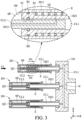
- FIG. 1 shows a schematic view of a myofascial trigger point and acupuncture point stimulator 1 and a fluid ejection device 900 in accordance with an embodiment of the present invention.
- the acupuncture point stimulator 1 may be a stimulating device for stimulating a myofascial trigger point, an acupuncture point, and skin of a human body, including a base 10 and a contact assembly 20.
- the fluid ejection device 900 may be an ejection device holding fluids of medical use, ejecting the fluid(s) to a myofascial trigger point, an acupuncture point, or skin of a human body.
- the fluids may consist of gas and/or liquid, such as hydrogen, oxygen, nitrogen, carbon dioxide, ozone, nitrous oxide, or any other suitable gas or liquid for anesthesia.
- the myofascial trigger point and acupuncture point stimulator 1 may be installed at a front end of the fluid ejection device 900, performing stimulation of the acupuncture point and the skin of the human body.
- the fluid inside the fluid ejection device 900 may pass through the myofascial trigger point and acupuncture point stimulator 1 to the acupuncture point and the skin of the human body.
- the fluid ejection device 900 is not limited to the one illustrated in FIG. 1 , but it may be any other types of ejection device.
- the fluid ejection device may be a box shape ejection device with a long connecting tube that is connected to the myofascial trigger point and acupuncture point stimulator 1.
- the structure of aforementioned myofascial trigger point and acupuncture point stimulator 1 will be described in detail below.
- FIG. 2 shows a cross-sectional schematic view of the aforementioned myofascial trigger point and acupuncture point stimulator 1. It should be noted that three contact members 201 are illustrated in FIG. 2 for concise and clear purposes.
- the myofascial trigger point and acupuncture point stimulator 1 generally includes the base 10 and the contact assembly 20.
- the base 10 includes a body 101 and a fixed tube assembly 102 that is fixedly disposed on the body 101 and protrudes from the body 101.
- the fixed tube assembly 102 includes a plurality of fixed tubes 1021 (there are thirteen of fixed tubes in the present embodiment). Each of the fixed tubes 1021 has a long structure.
- the contact assembly 20 includes a plurality of long contact members 201.
- the number of the contact members 201 equals to the number of the aforementioned fixed tubes 1021.
- the contact members 201 are disposed on the fixed tubes 1021 and surrounding the fixed tubes 1021. Ends 201 C of the contact members 201 may be in direct contact with human skin.
- the myofascial trigger point and acupuncture point stimulator 1 further includes a resilient member E that surrounds an outer surface 1021R of the fixed tube 1021.
- the fixed tube 1021 is located inside the resilient member E that may be an extension spring.
- the resilient member E is located between the contact member 201 and the fixed tube 1021.
- the contact member 201 is movably disposed on the fixed tube 1021 via the resilient member E.
- the aforementioned contact member 201 may act as a movable tube with a tube body 2011 and an extending portion 2012.
- the extending portion 2012 is fixedly disposed inside the tube body 2011.
- the end of the extending portion 2012 is partially accommodated in the fixed tube 1021.
- the extending portion 2012 at least partially overlaps the fixed tube 1021.
- the aforementioned base 10 has a transmission channel CL1 that is located inside the body 101 and passes through every fixed tube 1021. A portion of the extending portion 2012 of the contact member 201 is disposed in the transmission channel CL1. The extending portion 2012 has a discharge channel CL2 with an L-shaped structure.
- the myofascial trigger point and acupuncture point stimulator 1 further includes a stopper ring B1 that is disposed at one end of the fixed tube 1021, stopping the gas or liquid in the transmission channel CL1 from entering the discharge channel CL2.
- the stopper ring B1 and its function will be described in detail in the following paragraphs.
- FIG. 3 shows a schematic view of one of the contact members 201 (the top contact member 201 in FIG. 3 ) of the contact assembly 20 in the communication position, while other contact members 201 are in the closed position.
- the aforementioned contact members 201 may be switchable between the closed position and the communication position relative to the fixed tubes 1021 of the base 10. Specifically, when a force F1 is applied to the contact members 201, the contact members 201 move in the first direction D1 relative to the base 10, along the fixed tubes 1021 toward the body 101. At this moment, the entrance Q1 of the discharge channel CL2 of the extending portion 2012 of the contact member 201 crosses over the stopper ring B1.
- the entrance Q1 crosses the stopper ring B1 from one side S1 to another side S2, so that the entrance Q1 becomes closer to the body 101 than the stopper ring B1.
- the discharge channel CL2 communicates with the transmission channel CL1, so that the gas or liquid in the transmission channel CL1 may pass through the discharge channel CL2, discharged from the outlet Q2 of the discharge channel CL2, performing stimulation of the skin, the myofascial trigger point and acupuncture point of human body.
- the contact members 201 may return to the closed position by the returning spring force of the resilient member E.
- the discharge channel CL2 of the contact member 201 moves further away from the body 101, i.e. in the second direction D2, returning from another side S2 to the side S1.
- the entrance Q1 of the discharge channel CL2 is blocked by the stopper ring B1, as shown in FIG. 2 , so that the gas or liquid in the transmission channel CL2 is no longer in communication with the discharge channel CL2.
- the outlet Q2 of the discharge channel CL2 is stopped from discharging gas or liquid.
- the contact members 201 since the contact members 201 is movably disposed on the base 10, switchable between the closed position and the communication position depending on whether a pressure is applied or not, the contact members 201 are extended or compressed, controlling the discharge of gas or liquid, thereby improving the convenience of usage.
- the discharge channel CL2 may communicate with the transmission channel CL1 simply by making the entrance Q1 of the discharge channel CL2 cross over the stopper ring B1.
- the contact members 201 may follow the bumpy contour of the skin while transmitting gas or liquid, adequately fit on the skin surface SS for valid contact, as shown in FIG. 4 , broadening the range of usability.
- the transmission channel CL1 of the contact member 201 of the present embodiment pressurizes the liquid in direct contact with the skin, so that the liquid may be applied directly to the skin surface in a short period of time, stimulating the myofascial trigger points or acupuncture points, such as fasciae, nerves, muscles, or joints etc.
- ESWT extracorporeal shockwave therapy
- the stimulator of the present application is more effective since it not only has the effect of mechanical energy produced by fluid pressure, but it also has the effect produced by the particles of fluid itself that is applied to the skin for the tissues.
- a seal ring B2 is disposed on the exterior of the fixed tubes 1021, the inner wall IW of the tube body 2011 of the contact member 201, and the outer surface 1021R of the fixed tube 1021, for further preventing liquid or gas from overflow or effusion.
- the fluid may pass through the stopper ring B1 and enter the space SP of the tube body 2011.
- the seal ring B2 the fluid may be effectively stopped from entering the space accommodating the resilient member E or from further effusion.
- the fluid is at least maintained in the space SP, being able to pass through the stopper ring B1 again and then enter the entrance Q1, following the normal flowing direction.
- the contact assembly 20 may have a different amount of contact members 201, such as five, seven (see the myofascial trigger point and acupuncture point stimulator 1' and 1" shown in FIGs. 5A-5B ), or any other suitable numbers.
- the number of the fixed tubes 1021 of the fixed tube assembly 102 of the base 10 matches the number of the contact members 201.
- 60 or 90 degree angles are formed between the connecting lines (the dashed lines) of central axes C of adjacent contact members 201.
- the contact assembly 20 may only include one contact member 201, equipped with the base 10 with only one fixed tube 1021, which may still stimulate the skin, the myofascial trigger point and acupuncture point of human body.
- the discharge channels CL2 of the contact members 201 are shown as having L-shaped structures in the present embodiment.
- the discharge channels CL2 may have T-shaped structures. That is, each of the upper and lower sides of the discharge channel CL2 (in the direction of z-axis) has one entrance Q1, respectively. When in the communication position, the two entrances of the discharge channel CL2 both cross over the stopper ring B1, communicating with the transmission channel CL1. Therefore, liquid may flow into the discharge channel CL2 and be discharged from the outlet Q2.
- the myofascial trigger point and acupuncture point stimulator may further include one or more chucks 401 that may be negative pressure vacuum chucks and disposed at the base 10, as the myofascial trigger point and acupuncture point stimulators 1′′′ and 1 ⁇ shown in FIGs. 5C-5D .
- One or more of the pluralities of contact members 201 of the contact assembly 20 may be changed to one or more chucks 401 for sucking on the skin surface.
- the contact member 201 in the center in FIG. 5A may be changed to a chuck 401.
- the contact members 201 are disposed around the chuck 401.
- a chuck 401 is disposed adjacent to every adjacent contact member 201, such as the three chucks 401 shown in FIG. 5D .
- a chuck 401 is disposed at the location where it is adjacent to every contact member 201.
- the length of the chucks 401 may be equal to the length of the aforementioned contact members 201 (in the direction of x-axis).
- the chucks 401 may also be extendable and compressible. That is, the chucks 401 may be extended or compressed along with the contact members 201 for fitting on the skin surface SS when in contact.
- the chucks 401 may be connected to a negative pressure chamber. When the chamber has negative pressure, the chucks 401 may suck on the skin.
- FIG. 6 show a schematic view of a plurality of myofascial trigger point and acupuncture point stimulators 1 equipped on an embarkation type ejection device 900', making it a myofascial trigger point and acupuncture point stimulating system 1000.
- the embarkation type ejection device 900' may be a mattress equipped with an ejection system JR that may communicate with an external device for supplying liquid (not shown).
- the plurality of myofascial trigger point and acupuncture point stimulators 1 are disposed on the surface of the embarkation type ejection device 900'.
- the bases 10 of the myofascial trigger point and acupuncture point stimulators 1 are embedded inside the embarkation type ejection device 900' while the contact members 201 are exposed.
- the transmission channels CL1 of the bases 10 communicate with the ejection system JR for the liquid to flow pass the transmission channels CL1.
- this myofascial trigger point and acupuncture point stimulating system 1000 When a human body lies or sits on this myofascial trigger point and acupuncture point stimulating system 1000, the hip, the thigh, the hands, the scalp, the neck, and the back (but not limited thereto) etc. are pressed by the myofascial trigger point and acupuncture point stimulators 1. By the communication between the transmission channels CL1 with the discharge channels CL2, fluid for pressing the myofascial trigger point and acupuncture point is discharged for stimulation. When the human body leaves the myofascial trigger point and acupuncture point stimulating system, the transmission channels CL1 no longer communicate with the discharge channels CL2, so that the liquid supply is stopped.
- the myofascial trigger point and acupuncture point stimulator 1 may form another myofascial trigger point and acupuncture point stimulating system by being equipped with other types of ejection systems 900', such as, with a seat type ejection device that allows users to sit on this myofascial trigger point and acupuncture point stimulating system for stimulation; or with a pillow type ejection device that allows users to rest their head on the system for stimulation.
- other types of ejection systems 900' such as, with a seat type ejection device that allows users to sit on this myofascial trigger point and acupuncture point stimulating system for stimulation; or with a pillow type ejection device that allows users to rest their head on the system for stimulation.
- FIG. 7 shows a schematic view of the myofascial trigger point and acupuncture point stimulator 2 in accordance with another embodiment of the present invention.
- the myofascial trigger point and acupuncture point stimulator 2 may also act as a stimulating device for stimulating acupunctures points or skin of human bodies, including a base 10' and a contact assembly 20' for contacting the myofascial trigger point and acupuncture point or skin of a human body, ejecting the medical liquid from or stored in the base 10' out to the human body.
- the detailed structures of the base 10' and the contact assembly 20' will be described below.
- FIG. 8 shows a schematic view of a contact member 201' of the contact assembly 20' and a portion of the base 10';
- FIG. 9 shows a cross-sectional schematic view of the contact member 201' disposed at the base 10'.
- the contact assembly 20' includes a plurality of contact members 201'.
- Each of the contact members 201' has a plurality of (two) movable tubes 2011' inserted into the base 10'.
- the end of the movable tube 2011' that is closer to the base 10' has a protruding structure (on the XY plane) 20111' for snapping onto the base 10'.
- the protruding structure may have a structure that is like a nut, or any other structure that is suitable for snapping onto the base 10'.
- the other end that is further away from the base 10' has an abutting unit 2013' for fitting closely on the human skin surface.
- the abutting unit 2013' may include materials such as silicone, rubber, or thermoplastic elastomer (TPE), etc.
- TPE thermoplastic elastomer
- the abutting unit 2013' has a rectangular structure.
- the abutting unit 2013' may have a polygonal structure, such as a triangular or pentagonal structure.
- a resilient member E' which may be a compress spring, is disposed between the two movable tubes 2011'.
- the myofascial trigger point and acupuncture point stimulator 2 further includes a positioning ring assembly 30 that has an upper positioning ring 31 and a lower positioning ring 32.
- the upper positioning ring 31 and the lower positioning ring 32 are disposed at the abutting unit 2013' and the base 10', respectively.
- the upper positioning ring 31 and the lower positioning ring 32 are located outside the resilient member E' for positioning the resilient member E'.
- the stopper ring B1 is installed within the casing 10F' of the base 10' to surround the outer surface of the movable tube 2011'.
- the contact member 201' (or the movable tube 2011' thereof) is directly inserted into the base 10' in the present embodiment.
- the fixed tube in the previous embodiment is not required to be installed to the base 10', thereby reducing the production cost and lowering the difficulty of assembling.
- the compressed resilient member E' applies a resilient rebound force to the abutting unit 2013' of the contact member 201', so that the contact member 201' returns to its initial position relative to the base 10' (as shown in FIG. 9 ).
- the entrance Q1 of the discharge channel CL2' no longer communicates with the transmission channel CL1'.
- the entrance Q1 is blocked and covered by the stopper ring B1 and the casing 10F' of the base 10', stopping the fluid from being discharged from the outlet Q2.
- the myofascial trigger point and acupuncture point stimulator 2 of the present embodiment may also be equipped with the embarkation type ejection device 900', forming another myofascial trigger point and acupuncture point stimulating system.
- the base 10' is embedded inside the embarkation type ejection device 900', exposing the contact member 201'.
- the pressed contact member 201' may move downward, so that the discharge channel CL2' communicates with the transmission channel CL1', and then fluid may be discharged.
- the embodiment of the present invention provides a myofascial trigger point and acupuncture point stimulator, configured to connect a fluid ejection device.
- the stimulator includes a base and at least one contact member.
- the base has at least one transmission channel.
- the contact member is movably disposed on the base and has a discharge channel.
- the contact member is switchable between a closed position and a communication position. When the contact member moves from the closed position to the communication position relative to the base, the discharge channel of the contact member changes from not communicating with the transmission channel to communicating with the transmission channel for ejecting the fluid provided by the fluid ejection device.
- the contact member may switch between the closed position and the communication position so that the discharge channel communicates or not communicates with the transmission channel, improving the convenience for stimulating the myofascial trigger point and acupuncture point of human bodies;
- the contact assembly that is configured with multiple movable contact members increases the fitness to the human skin surface, improving the ejection effect for human's body parts.
- the contact member is directly disposed on the base, reducing the assemble difficulty and the cost.
- first, second, and the like are merely generic identifiers and, as such, may be interchanged in various embodiments.
- an element may be referred to as a "first” element in some embodiments, the element may be referred to as a "second” element in other embodiments.
Landscapes
- Health & Medical Sciences (AREA)
- Rehabilitation Therapy (AREA)
- Epidemiology (AREA)
- Pain & Pain Management (AREA)
- Physical Education & Sports Medicine (AREA)
- Life Sciences & Earth Sciences (AREA)
- Animal Behavior & Ethology (AREA)
- General Health & Medical Sciences (AREA)
- Public Health (AREA)
- Veterinary Medicine (AREA)
- Finger-Pressure Massage (AREA)
- Massaging Devices (AREA)
Claims (11)
- Myofaszialer Triggerpunkt- und Akupunkturpunktstimulator (1), konfiguriert, um eine Fluidausstoßvorrichtung (900) mit einer Hautoberfläche (SS) in direktem Kontakt mit dem myofaszialen Triggerpunkt- und Akupunkturpunktstimulator zu verbinden und einen Fluiddruck darauf zu übertragen, dadurch gekennzeichnet, dass der Stimulator Folgendes umfasst:einen Unterbau (10) mit einem Übertragungskanal (CL1); undmindestens ein Kontaktelement (201), das bewegbar an dem Unterbau (10) angeordnet ist und einen Ableitungskanal (CL2) aufweist, wobei ein Ende (201C) des Kontaktelements konfiguriert ist, um direkt mit einer Hautoberfläche (SS) in Kontakt zu sein, und das Kontaktglied zwischen einer geschlossenen Position und einer Verbindungsposition schaltbar ist;wobei sich das Kontaktelement in Richtung des Ableitungskanals von der geschlossenen Position in die Verbindungsposition bewegt, wenn eine Kraft auf das eine Ende des Kontaktelements aufgebracht wird;wobei, wenn sich das Kontaktelement von der geschlossenen Position in die Verbindungsposition relativ zu dem Unterbau bewegt, der Ableitungskanal des Kontaktelements von nicht in Verbindung mit dem Übertragungskanal zu in Verbindung mit dem Übertragungskanal zum Ausstoßen des von der Fluidausstoßvorrichtung bereitgestellten Fluids auf die Hautoberfläche wechselt.
- Myofaszialer Triggerpunkt- und Akupunkturpunktstimulator (1) nach Anspruch 1, wobei der Unterbau einen Körper (101) und ein festes Rohr (1201) umfasst, wobei das feste Rohr an dem Körper angeordnet ist, und der Übertragungskanal (CL1) durch das feste Rohr hindurchgeht, und das Kontaktelement (201) bewegbar an dem festen Rohr angeordnet ist.
- Myofaszialer Triggerpunkt- und Akupunkturpunktstimulator (1) nach Anspruch 2, ferner umfassend einen Anschlagring (B1), der an einem Ende des festen Rohrs (1021) angeordnet ist, wobei sich ein Eingang (Q1) des Ableitungskanals (CL2) an einer Seite (S1) des Anschlagrings befindet und durch den Anschlagring daran gehindert wird, mit dem Übertragungskanal (CL1) in Verbindung zu treten, wenn sich das Kontaktelement (201) in der geschlossenen Position befindet, wobei der Eingang durch den Anschlagring zu einer anderen Seite (S2) des Anschlagrings hindurchgeht, um mit dem Übertragungskanal in Verbindung zu treten, wenn sich das Kontaktelement in der Verbindungsposition befindet.
- Myofaszialer Triggerpunkt- und Akupunkturpunktstimulator (1) nach Anspruch 3, wobei der Ableitungskanal (CL2) des Kontaktelements (201) eine L-förmige oder T-förmige Struktur aufweist, wobei sich der Anschlagring (B1) näher an dem Körper (101) als der Eingang (Q1) befindet, wenn sich das Kontaktelement in der geschlossenen Position befindet, und wobei sich der Eingang näher an dem Körper als der Anschlagring befindet, wenn sich das Kontaktelement in der Verbindungsposition befindet.
- Myofaszialer Triggerpunkt- und Akupunkturpunktstimulator (1) nach Anspruch 2, ferner umfassend ein elastisches Element (E), das um das feste Rohr (1021) angeordnet ist und das feste Rohr an das Kontaktelement (201) anschließt, sodass das Kontaktelement auf dem festen Rohr gleitbar ist.
- Myofaszialer Triggerpunkt- und Akupunkturpunktstimulator (1) nach Anspruch 2, ferner umfassend einen Dichtring (B2), der um eine Außenfläche (1021R) des festen Rohres (1021) angeordnet ist, sich zwischen dem Kontaktelement (201) und dem festen Rohr befindet und an einer Innenwand (IW) des Kontaktelements anliegt.
- Myofaszialer Triggerpunkt- und Akupunkturpunktstimulator (1) nach Anspruch 3, ferner umfassend eine Vielzahl von Kontaktelementen (201), wobei jedes Kontaktelement eine Mittelachse (C) aufweist, wobei zwischen den benachbarten Mittelachsen der Kontaktelemente 60- bis 90-Grad-Winkel gebildet sind.
- Myofaszialer Triggerpunkt- und Akupunkturpunktstimulator (2) nach Anspruch 1, wobei das Kontaktelement (201') eine Vielzahl von bewegbaren Rohren (2011') umfasst, die teilweise in dem Unterbau (10') eingesetzt sind, wobei die bewegbaren Rohre relativ zur Basis bewegbar und zwischen der geschlossenen Position und der Verbindungsposition schaltbar sind;wobei jeder Eingang (Q1) des Ableitungskanals (CL2') der bewegbaren Rohre durch ein Gehäuse (10F') des Unterbaus blockiert ist, wenn sich die bewegbaren Rohre in der geschlossenen Position befinden;wobei jeder Ableitungskanal der bewegbaren Rohre mit dem Übertragungskanal (CL1') des Unterbaus in Verbindung steht, wenn sich die bewegbaren Rohre in der geschlossenen Position befinden.
- Myofaszialer Triggerpunkt- und Akupunkturpunktstimulator (2) nach Anspruch 8, wobei das Kontaktelement (201') ferner eine Anliegeeinheit (2013') umfasst, die an den bewegbaren Rohren (2011') angeordnet ist, wobei die Anliegeeinheit Materialien aus Silikon, Gummi oder thermoplastischem Elastomer aufweist.
- Myofaszialer Triggerpunkt- und Akupunkturpunktstimulator (2) nach Anspruch 9, ferner umfassend ein elastisches Element (E'), das zwischen den bewegbaren Rohren (2011') angeordnet ist und die Anliegeeinheit (2013') an den Unterbau (10') anschließt, wobei die bewegbaren Rohre über das elastische Element zwischen der geschlossenen Position und der Verbindungsposition schaltbar sind.
- Myofaszialer Triggerpunkt- und Akupunkturpunktstimulator (1) nach Anspruch 1, ferner umfassend ein an dem Unterbau (10) angeordnetes und an die Hautoberfläche (SS) adsorbiertes Futter (401) .
Applications Claiming Priority (2)
| Application Number | Priority Date | Filing Date | Title |
|---|---|---|---|
| US201862732144P | 2018-09-17 | 2018-09-17 | |
| PCT/CN2019/106007 WO2020057468A1 (zh) | 2018-09-17 | 2019-09-16 | 激痛点与穴位刺激器 |
Publications (4)
| Publication Number | Publication Date |
|---|---|
| EP3854370A1 EP3854370A1 (de) | 2021-07-28 |
| EP3854370A4 EP3854370A4 (de) | 2022-06-22 |
| EP3854370B1 true EP3854370B1 (de) | 2024-04-17 |
| EP3854370C0 EP3854370C0 (de) | 2024-04-17 |
Family
ID=69888346
Family Applications (1)
| Application Number | Title | Priority Date | Filing Date |
|---|---|---|---|
| EP19861863.9A Active EP3854370B1 (de) | 2018-09-17 | 2019-09-16 | Triggerpunkt- und akupunkturpunktstimulator |
Country Status (6)
| Country | Link |
|---|---|
| US (1) | US12070435B2 (de) |
| EP (1) | EP3854370B1 (de) |
| JP (1) | JP7289560B2 (de) |
| CN (1) | CN112672724B (de) |
| TW (1) | TWI722570B (de) |
| WO (1) | WO2020057468A1 (de) |
Families Citing this family (1)
| Publication number | Priority date | Publication date | Assignee | Title |
|---|---|---|---|---|
| JP7271034B1 (ja) * | 2022-11-29 | 2023-05-11 | 株式会社Healthy Body | 体力を増進するためのトレーニング方法 |
Family Cites Families (34)
| Publication number | Priority date | Publication date | Assignee | Title |
|---|---|---|---|---|
| CH168278A (de) * | 1933-03-11 | 1934-03-31 | Wilhelm Dr Winteler | Gesichtsmaske. |
| US2330732A (en) * | 1940-02-06 | 1943-09-28 | Elmer E Oestrike | Method of forming helmets |
| US4807604A (en) * | 1987-12-11 | 1989-02-28 | Heriberto Canela | Scalp massager |
| CN88205972U (zh) * | 1988-05-20 | 1988-12-28 | 贾成建 | 热流喷灸器 |
| CN2281177Y (zh) * | 1996-10-05 | 1998-05-13 | 杜永义 | 头部经穴理疗器 |
| CN2348833Y (zh) * | 1998-02-19 | 1999-11-17 | 汪午生 | 气体治疗仪用气体治疗头 |
| JP2001046455A (ja) * | 1999-08-13 | 2001-02-20 | Rinnai Corp | 浴槽内の温水噴出式マッサージ装置 |
| JP2001046464A (ja) * | 1999-08-13 | 2001-02-20 | Rinnai Corp | 温水噴出式足の裏マッサージ装置 |
| IT1308829B1 (it) * | 1999-09-21 | 2002-01-11 | Gevipi Ag | Valvola automatica per la stabilizzazione di un dispositivomiscelatore termostatico. |
| US6648850B2 (en) * | 2001-06-08 | 2003-11-18 | Bioject, Inc. | Durable needle-less jet injector apparatus and method |
| DE10348614B3 (de) * | 2003-10-20 | 2005-05-25 | Cnc Technik | Verfahren zur Herstellung einer Massagemaske, hierfür geeignetes Anfertigungsverfahren, wie auch damit hergestellte Massagemaske |
| CN1782412A (zh) * | 2004-11-30 | 2006-06-07 | 乐金电子(天津)电器有限公司 | 卷轴压缩机的高温防止装置 |
| DE602005022602D1 (de) | 2005-12-21 | 2010-09-09 | Zadeh David Khorassani | Vorrichtung zur Massage mit konstantem Druck |
| US7901369B2 (en) * | 2006-07-14 | 2011-03-08 | Quinn Rebecca E | Massage tool and method for treatment of trigger points and other soft tissue disorders |
| JP2009095545A (ja) * | 2007-10-18 | 2009-05-07 | Inax Corp | 照射装置 |
| CN201533912U (zh) * | 2009-11-28 | 2010-07-28 | 王汉钦 | 一种药气蒸疗床 |
| WO2011074718A1 (ko) * | 2009-12-16 | 2011-06-23 | 주식회사 티앤아이 | 물리 치료용 근막 이완기 |
| CN101836856B (zh) * | 2010-05-14 | 2011-08-31 | 王玉芝 | 一种携带式温痛测定器及温痛测定装置 |
| CN202161538U (zh) * | 2011-06-13 | 2012-03-14 | 珠海市庭佑化妆配件有限公司 | 具有安全开关的震动按摩容器 |
| US20130138143A1 (en) * | 2011-11-26 | 2013-05-30 | Gennady Chechelnitsky | Acupressure device with a plurality of individually-controlled applicators having protrusions extending therefrom |
| JP6308644B2 (ja) * | 2011-11-29 | 2018-04-11 | 西川 高弘 | 頭皮の美容器 |
| KR101293293B1 (ko) * | 2012-02-06 | 2013-08-09 | 이정렬 | 경혈용 자극기 및 이를 구비하는 경혈자극장치 |
| TWM435268U (en) * | 2012-03-07 | 2012-08-11 | Min Hwei College Of Health Care Man | Massage rod |
| TWM438273U (en) * | 2012-04-09 | 2012-10-01 | A Hot Internat Co Ltd | Warming-type massage device |
| US20140276534A1 (en) * | 2013-03-14 | 2014-09-18 | Nova Pneumatics LLC | Needleless injector |
| WO2014162808A1 (ja) * | 2013-04-05 | 2014-10-09 | Sato Hirohiko | 弁装置及びこれを用いたシャワー装置 |
| CN103239356A (zh) * | 2013-05-28 | 2013-08-14 | 哈尔滨市瑞达电站成套设备厂 | 液体流体灸治疗仪及使用方法 |
| CN104998354B (zh) * | 2015-08-06 | 2019-04-26 | 广州龙之杰科技有限公司 | 一种弹道式体外冲击波治疗手柄 |
| CN106215287A (zh) * | 2016-08-15 | 2016-12-14 | 盛婷婷 | 一种用于皮肤护理的穴位注射装置 |
| CN108392700B (zh) * | 2017-02-02 | 2020-12-22 | 黄国伦 | 加压气体注射装置及方法 |
| TWM545591U (zh) | 2017-04-11 | 2017-07-21 | 明基材料股份有限公司 | 攜帶型負壓裝置 |
| CN107296745B (zh) * | 2017-06-20 | 2019-07-02 | 南宁腾科宝迪生物科技有限公司 | 一种快速镇痛穴位压力刺激贴及其使用方法 |
| US10470970B2 (en) * | 2017-07-11 | 2019-11-12 | Theragun, LLC | Attachment system for a plurality of treatment members |
| CN107753267B (zh) * | 2017-11-30 | 2020-03-03 | 广东美的安川服务机器人有限公司 | 冲击波治疗手柄及其控制方法、冲击波治疗系统 |
-
2019
- 2019-09-16 EP EP19861863.9A patent/EP3854370B1/de active Active
- 2019-09-16 US US17/276,600 patent/US12070435B2/en active Active
- 2019-09-16 JP JP2021515184A patent/JP7289560B2/ja active Active
- 2019-09-16 CN CN201980058570.7A patent/CN112672724B/zh active Active
- 2019-09-16 WO PCT/CN2019/106007 patent/WO2020057468A1/zh not_active Ceased
- 2019-09-17 TW TW108133331A patent/TWI722570B/zh active
Also Published As
| Publication number | Publication date |
|---|---|
| EP3854370A4 (de) | 2022-06-22 |
| WO2020057468A1 (zh) | 2020-03-26 |
| CN112672724A (zh) | 2021-04-16 |
| JP2022502123A (ja) | 2022-01-11 |
| JP7289560B2 (ja) | 2023-06-12 |
| TWI722570B (zh) | 2021-03-21 |
| CN112672724B (zh) | 2023-12-01 |
| US12070435B2 (en) | 2024-08-27 |
| TW202011923A (zh) | 2020-04-01 |
| EP3854370A1 (de) | 2021-07-28 |
| EP3854370C0 (de) | 2024-04-17 |
| US20210259920A1 (en) | 2021-08-26 |
Similar Documents
| Publication | Publication Date | Title |
|---|---|---|
| EP2583713A3 (de) | Polster für eine Atemmaske | |
| CN2899842Y (zh) | 美容按摩面罩 | |
| EP3854370B1 (de) | Triggerpunkt- und akupunkturpunktstimulator | |
| KR102218162B1 (ko) | 탄소 섬유를 주 재료로 하는 고압 산소 치료장치 | |
| US20130138143A1 (en) | Acupressure device with a plurality of individually-controlled applicators having protrusions extending therefrom | |
| CN217245507U (zh) | 熏蒸出气结构、熏蒸仪及熏蒸护膝 | |
| JP2020089625A (ja) | ソフトネスが調整可能なスプリング入りマットレス | |
| KR102255605B1 (ko) | 흡인펌프 밸브노즐 및 이를 포함하는 부항기 | |
| CN211023851U (zh) | 一种手臂康复训练仪 | |
| CN115581855A (zh) | 一种经颅磁刺激装置 | |
| CN215960602U (zh) | 微电流刺激眼罩 | |
| CN222640890U (zh) | 一种肿瘤内科化疗后抗冷刺激护理护具 | |
| KR20170003659U (ko) | 음압설정이 용이한 음압을 이용한 석션 마사지기 | |
| CN211214736U (zh) | 一种用于肿瘤治疗的皮下埋藏式药物输注装置 | |
| KR20210056142A (ko) | 공기 배출을 위한 솔레노이드 밸브를 포함하는 공기 제어 시스템 및 이를 포함하는 스마트 의자 | |
| CN206355312U (zh) | 天灸保健治疗带 | |
| KR200208737Y1 (ko) | 부항기 | |
| KR102806972B1 (ko) | 마사지용 롤러 조립체 | |
| CN219354634U (zh) | 一种中医康复用药物熏蒸装置 | |
| CN223392182U (zh) | 颈枕及颈枕枕芯 | |
| CN215915381U (zh) | 一种改良防压疮波浪气垫床 | |
| US11497843B2 (en) | Negative pressure device including expandable segment | |
| CN218419568U (zh) | 一种分段式按摩浴缸 | |
| CN103486287A (zh) | 医用气体开关 | |
| CN211357482U (zh) | 具有气囊结构的激光治疗仪 |
Legal Events
| Date | Code | Title | Description |
|---|---|---|---|
| STAA | Information on the status of an ep patent application or granted ep patent |
Free format text: STATUS: THE INTERNATIONAL PUBLICATION HAS BEEN MADE |
|
| PUAI | Public reference made under article 153(3) epc to a published international application that has entered the european phase |
Free format text: ORIGINAL CODE: 0009012 |
|
| STAA | Information on the status of an ep patent application or granted ep patent |
Free format text: STATUS: REQUEST FOR EXAMINATION WAS MADE |
|
| 17P | Request for examination filed |
Effective date: 20210416 |
|
| AK | Designated contracting states |
Kind code of ref document: A1 Designated state(s): AL AT BE BG CH CY CZ DE DK EE ES FI FR GB GR HR HU IE IS IT LI LT LU LV MC MK MT NL NO PL PT RO RS SE SI SK SM TR |
|
| DAV | Request for validation of the european patent (deleted) | ||
| DAX | Request for extension of the european patent (deleted) | ||
| REG | Reference to a national code |
Ref country code: DE Ref legal event code: R079 Free format text: PREVIOUS MAIN CLASS: A61H0039000000 Ipc: A61H0039040000 Ref document number: 602019050617 Country of ref document: DE |
|
| A4 | Supplementary search report drawn up and despatched |
Effective date: 20220519 |
|
| RIC1 | Information provided on ipc code assigned before grant |
Ipc: A61H 39/04 20060101AFI20220513BHEP |
|
| GRAP | Despatch of communication of intention to grant a patent |
Free format text: ORIGINAL CODE: EPIDOSNIGR1 |
|
| STAA | Information on the status of an ep patent application or granted ep patent |
Free format text: STATUS: GRANT OF PATENT IS INTENDED |
|
| INTG | Intention to grant announced |
Effective date: 20231120 |
|
| GRAS | Grant fee paid |
Free format text: ORIGINAL CODE: EPIDOSNIGR3 |
|
| GRAA | (expected) grant |
Free format text: ORIGINAL CODE: 0009210 |
|
| STAA | Information on the status of an ep patent application or granted ep patent |
Free format text: STATUS: THE PATENT HAS BEEN GRANTED |
|
| AK | Designated contracting states |
Kind code of ref document: B1 Designated state(s): AL AT BE BG CH CY CZ DE DK EE ES FI FR GB GR HR HU IE IS IT LI LT LU LV MC MK MT NL NO PL PT RO RS SE SI SK SM TR |
|
| REG | Reference to a national code |
Ref country code: GB Ref legal event code: FG4D |
|
| REG | Reference to a national code |
Ref country code: CH Ref legal event code: EP |
|
| REG | Reference to a national code |
Ref country code: IE Ref legal event code: FG4D Ref country code: DE Ref legal event code: R096 Ref document number: 602019050617 Country of ref document: DE |
|
| U01 | Request for unitary effect filed |
Effective date: 20240424 |
|
| U07 | Unitary effect registered |
Designated state(s): AT BE BG DE DK EE FI FR IT LT LU LV MT NL PT SE SI Effective date: 20240503 |
|
| PG25 | Lapsed in a contracting state [announced via postgrant information from national office to epo] |
Ref country code: IS Free format text: LAPSE BECAUSE OF FAILURE TO SUBMIT A TRANSLATION OF THE DESCRIPTION OR TO PAY THE FEE WITHIN THE PRESCRIBED TIME-LIMIT Effective date: 20240817 |
|
| PG25 | Lapsed in a contracting state [announced via postgrant information from national office to epo] |
Ref country code: HR Free format text: LAPSE BECAUSE OF FAILURE TO SUBMIT A TRANSLATION OF THE DESCRIPTION OR TO PAY THE FEE WITHIN THE PRESCRIBED TIME-LIMIT Effective date: 20240417 |
|
| PG25 | Lapsed in a contracting state [announced via postgrant information from national office to epo] |
Ref country code: GR Free format text: LAPSE BECAUSE OF FAILURE TO SUBMIT A TRANSLATION OF THE DESCRIPTION OR TO PAY THE FEE WITHIN THE PRESCRIBED TIME-LIMIT Effective date: 20240718 |
|
| PG25 | Lapsed in a contracting state [announced via postgrant information from national office to epo] |
Ref country code: ES Free format text: LAPSE BECAUSE OF FAILURE TO SUBMIT A TRANSLATION OF THE DESCRIPTION OR TO PAY THE FEE WITHIN THE PRESCRIBED TIME-LIMIT Effective date: 20240417 |
|
| PG25 | Lapsed in a contracting state [announced via postgrant information from national office to epo] |
Ref country code: PL Free format text: LAPSE BECAUSE OF FAILURE TO SUBMIT A TRANSLATION OF THE DESCRIPTION OR TO PAY THE FEE WITHIN THE PRESCRIBED TIME-LIMIT Effective date: 20240417 |
|
| U20 | Renewal fee for the european patent with unitary effect paid |
Year of fee payment: 6 Effective date: 20240925 |
|
| PG25 | Lapsed in a contracting state [announced via postgrant information from national office to epo] |
Ref country code: PL Free format text: LAPSE BECAUSE OF FAILURE TO SUBMIT A TRANSLATION OF THE DESCRIPTION OR TO PAY THE FEE WITHIN THE PRESCRIBED TIME-LIMIT Effective date: 20240417 Ref country code: NO Free format text: LAPSE BECAUSE OF FAILURE TO SUBMIT A TRANSLATION OF THE DESCRIPTION OR TO PAY THE FEE WITHIN THE PRESCRIBED TIME-LIMIT Effective date: 20240717 Ref country code: IS Free format text: LAPSE BECAUSE OF FAILURE TO SUBMIT A TRANSLATION OF THE DESCRIPTION OR TO PAY THE FEE WITHIN THE PRESCRIBED TIME-LIMIT Effective date: 20240817 Ref country code: HR Free format text: LAPSE BECAUSE OF FAILURE TO SUBMIT A TRANSLATION OF THE DESCRIPTION OR TO PAY THE FEE WITHIN THE PRESCRIBED TIME-LIMIT Effective date: 20240417 Ref country code: GR Free format text: LAPSE BECAUSE OF FAILURE TO SUBMIT A TRANSLATION OF THE DESCRIPTION OR TO PAY THE FEE WITHIN THE PRESCRIBED TIME-LIMIT Effective date: 20240718 Ref country code: ES Free format text: LAPSE BECAUSE OF FAILURE TO SUBMIT A TRANSLATION OF THE DESCRIPTION OR TO PAY THE FEE WITHIN THE PRESCRIBED TIME-LIMIT Effective date: 20240417 Ref country code: RS Free format text: LAPSE BECAUSE OF FAILURE TO SUBMIT A TRANSLATION OF THE DESCRIPTION OR TO PAY THE FEE WITHIN THE PRESCRIBED TIME-LIMIT Effective date: 20240717 |
|
| REG | Reference to a national code |
Ref country code: DE Ref legal event code: R097 Ref document number: 602019050617 Country of ref document: DE |
|
| PG25 | Lapsed in a contracting state [announced via postgrant information from national office to epo] |
Ref country code: CZ Free format text: LAPSE BECAUSE OF FAILURE TO SUBMIT A TRANSLATION OF THE DESCRIPTION OR TO PAY THE FEE WITHIN THE PRESCRIBED TIME-LIMIT Effective date: 20240417 |
|
| PG25 | Lapsed in a contracting state [announced via postgrant information from national office to epo] |
Ref country code: SK Free format text: LAPSE BECAUSE OF FAILURE TO SUBMIT A TRANSLATION OF THE DESCRIPTION OR TO PAY THE FEE WITHIN THE PRESCRIBED TIME-LIMIT Effective date: 20240417 Ref country code: RO Free format text: LAPSE BECAUSE OF FAILURE TO SUBMIT A TRANSLATION OF THE DESCRIPTION OR TO PAY THE FEE WITHIN THE PRESCRIBED TIME-LIMIT Effective date: 20240417 |
|
| PG25 | Lapsed in a contracting state [announced via postgrant information from national office to epo] |
Ref country code: SM Free format text: LAPSE BECAUSE OF FAILURE TO SUBMIT A TRANSLATION OF THE DESCRIPTION OR TO PAY THE FEE WITHIN THE PRESCRIBED TIME-LIMIT Effective date: 20240417 |
|
| PG25 | Lapsed in a contracting state [announced via postgrant information from national office to epo] |
Ref country code: SM Free format text: LAPSE BECAUSE OF FAILURE TO SUBMIT A TRANSLATION OF THE DESCRIPTION OR TO PAY THE FEE WITHIN THE PRESCRIBED TIME-LIMIT Effective date: 20240417 Ref country code: SK Free format text: LAPSE BECAUSE OF FAILURE TO SUBMIT A TRANSLATION OF THE DESCRIPTION OR TO PAY THE FEE WITHIN THE PRESCRIBED TIME-LIMIT Effective date: 20240417 Ref country code: RO Free format text: LAPSE BECAUSE OF FAILURE TO SUBMIT A TRANSLATION OF THE DESCRIPTION OR TO PAY THE FEE WITHIN THE PRESCRIBED TIME-LIMIT Effective date: 20240417 Ref country code: CZ Free format text: LAPSE BECAUSE OF FAILURE TO SUBMIT A TRANSLATION OF THE DESCRIPTION OR TO PAY THE FEE WITHIN THE PRESCRIBED TIME-LIMIT Effective date: 20240417 |
|
| PLBE | No opposition filed within time limit |
Free format text: ORIGINAL CODE: 0009261 |
|
| STAA | Information on the status of an ep patent application or granted ep patent |
Free format text: STATUS: NO OPPOSITION FILED WITHIN TIME LIMIT |
|
| 26N | No opposition filed |
Effective date: 20250120 |
|
| PG25 | Lapsed in a contracting state [announced via postgrant information from national office to epo] |
Ref country code: MC Free format text: LAPSE BECAUSE OF FAILURE TO SUBMIT A TRANSLATION OF THE DESCRIPTION OR TO PAY THE FEE WITHIN THE PRESCRIBED TIME-LIMIT Effective date: 20240417 |
|
| REG | Reference to a national code |
Ref country code: CH Ref legal event code: PL |
|
| PG25 | Lapsed in a contracting state [announced via postgrant information from national office to epo] |
Ref country code: CH Free format text: LAPSE BECAUSE OF NON-PAYMENT OF DUE FEES Effective date: 20240930 |
|
| PG25 | Lapsed in a contracting state [announced via postgrant information from national office to epo] |
Ref country code: IE Free format text: LAPSE BECAUSE OF NON-PAYMENT OF DUE FEES Effective date: 20240916 |
|
| U20 | Renewal fee for the european patent with unitary effect paid |
Year of fee payment: 7 Effective date: 20250702 |
|
| PGFP | Annual fee paid to national office [announced via postgrant information from national office to epo] |
Ref country code: GB Payment date: 20250701 Year of fee payment: 7 |
|
| PG25 | Lapsed in a contracting state [announced via postgrant information from national office to epo] |
Ref country code: CY Free format text: LAPSE BECAUSE OF FAILURE TO SUBMIT A TRANSLATION OF THE DESCRIPTION OR TO PAY THE FEE WITHIN THE PRESCRIBED TIME-LIMIT; INVALID AB INITIO Effective date: 20190916 |