EP3851621A2 - Sliding door system - Google Patents
Sliding door system Download PDFInfo
- Publication number
- EP3851621A2 EP3851621A2 EP20209433.0A EP20209433A EP3851621A2 EP 3851621 A2 EP3851621 A2 EP 3851621A2 EP 20209433 A EP20209433 A EP 20209433A EP 3851621 A2 EP3851621 A2 EP 3851621A2
- Authority
- EP
- European Patent Office
- Prior art keywords
- fastening
- bolt
- sliding door
- door leaf
- running rail
- Prior art date
- Legal status (The legal status is an assumption and is not a legal conclusion. Google has not performed a legal analysis and makes no representation as to the accuracy of the status listed.)
- Pending
Links
Images


Classifications
-
- E—FIXED CONSTRUCTIONS
- E05—LOCKS; KEYS; WINDOW OR DOOR FITTINGS; SAFES
- E05D—HINGES OR SUSPENSION DEVICES FOR DOORS, WINDOWS OR WINGS
- E05D5/00—Construction of single parts, e.g. the parts for attachment
- E05D5/02—Parts for attachment, e.g. flaps
- E05D5/0246—Parts for attachment, e.g. flaps for attachment to glass panels
-
- E—FIXED CONSTRUCTIONS
- E05—LOCKS; KEYS; WINDOW OR DOOR FITTINGS; SAFES
- E05D—HINGES OR SUSPENSION DEVICES FOR DOORS, WINDOWS OR WINGS
- E05D15/00—Suspension arrangements for wings
- E05D15/06—Suspension arrangements for wings for wings sliding horizontally more or less in their own plane
- E05D15/0621—Details, e.g. suspension or supporting guides
- E05D15/0626—Details, e.g. suspension or supporting guides for wings suspended at the top
- E05D15/063—Details, e.g. suspension or supporting guides for wings suspended at the top on wheels with fixed axis
- E05D15/0634—Details, e.g. suspension or supporting guides for wings suspended at the top on wheels with fixed axis with height adjustment
-
- E—FIXED CONSTRUCTIONS
- E05—LOCKS; KEYS; WINDOW OR DOOR FITTINGS; SAFES
- E05F—DEVICES FOR MOVING WINGS INTO OPEN OR CLOSED POSITION; CHECKS FOR WINGS; WING FITTINGS NOT OTHERWISE PROVIDED FOR, CONCERNED WITH THE FUNCTIONING OF THE WING
- E05F1/00—Closers or openers for wings, not otherwise provided for in this subclass
- E05F1/08—Closers or openers for wings, not otherwise provided for in this subclass spring-actuated, e.g. for horizontally sliding wings
- E05F1/16—Closers or openers for wings, not otherwise provided for in this subclass spring-actuated, e.g. for horizontally sliding wings for sliding wings
-
- E—FIXED CONSTRUCTIONS
- E05—LOCKS; KEYS; WINDOW OR DOOR FITTINGS; SAFES
- E05F—DEVICES FOR MOVING WINGS INTO OPEN OR CLOSED POSITION; CHECKS FOR WINGS; WING FITTINGS NOT OTHERWISE PROVIDED FOR, CONCERNED WITH THE FUNCTIONING OF THE WING
- E05F5/00—Braking devices, e.g. checks; Stops; Buffers
- E05F5/003—Braking devices, e.g. checks; Stops; Buffers for sliding wings
-
- E—FIXED CONSTRUCTIONS
- E05—LOCKS; KEYS; WINDOW OR DOOR FITTINGS; SAFES
- E05Y—INDEXING SCHEME RELATING TO HINGES OR OTHER SUSPENSION DEVICES FOR DOORS, WINDOWS OR WINGS AND DEVICES FOR MOVING WINGS INTO OPEN OR CLOSED POSITION, CHECKS FOR WINGS AND WING FITTINGS NOT OTHERWISE PROVIDED FOR, CONCERNED WITH THE FUNCTIONING OF THE WING
- E05Y2201/00—Constructional elements; Accessories therefore
- E05Y2201/20—Brakes; Disengaging means, e.g. clutches; Holders, e.g. locks; Stops; Accessories therefore
- E05Y2201/218—Holders
- E05Y2201/22—Locks
-
- E—FIXED CONSTRUCTIONS
- E05—LOCKS; KEYS; WINDOW OR DOOR FITTINGS; SAFES
- E05Y—INDEXING SCHEME RELATING TO HINGES OR OTHER SUSPENSION DEVICES FOR DOORS, WINDOWS OR WINGS AND DEVICES FOR MOVING WINGS INTO OPEN OR CLOSED POSITION, CHECKS FOR WINGS AND WING FITTINGS NOT OTHERWISE PROVIDED FOR, CONCERNED WITH THE FUNCTIONING OF THE WING
- E05Y2201/00—Constructional elements; Accessories therefore
- E05Y2201/40—Motors; Magnets; Springs; Weights; Accessories therefore
- E05Y2201/404—Motors; Magnets; Springs; Weights; Accessories therefore characterised by the function
- E05Y2201/41—Motors; Magnets; Springs; Weights; Accessories therefore characterised by the function for closing
- E05Y2201/412—Motors; Magnets; Springs; Weights; Accessories therefore characterised by the function for closing for the final closing movement
-
- E—FIXED CONSTRUCTIONS
- E05—LOCKS; KEYS; WINDOW OR DOOR FITTINGS; SAFES
- E05Y—INDEXING SCHEME RELATING TO HINGES OR OTHER SUSPENSION DEVICES FOR DOORS, WINDOWS OR WINGS AND DEVICES FOR MOVING WINGS INTO OPEN OR CLOSED POSITION, CHECKS FOR WINGS AND WING FITTINGS NOT OTHERWISE PROVIDED FOR, CONCERNED WITH THE FUNCTIONING OF THE WING
- E05Y2201/00—Constructional elements; Accessories therefore
- E05Y2201/40—Motors; Magnets; Springs; Weights; Accessories therefore
- E05Y2201/46—Magnets
- E05Y2201/462—Electromagnets
-
- E—FIXED CONSTRUCTIONS
- E05—LOCKS; KEYS; WINDOW OR DOOR FITTINGS; SAFES
- E05Y—INDEXING SCHEME RELATING TO HINGES OR OTHER SUSPENSION DEVICES FOR DOORS, WINDOWS OR WINGS AND DEVICES FOR MOVING WINGS INTO OPEN OR CLOSED POSITION, CHECKS FOR WINGS AND WING FITTINGS NOT OTHERWISE PROVIDED FOR, CONCERNED WITH THE FUNCTIONING OF THE WING
- E05Y2201/00—Constructional elements; Accessories therefore
- E05Y2201/60—Suspension or transmission members; Accessories therefore
- E05Y2201/622—Suspension or transmission members elements
- E05Y2201/64—Carriers
-
- E—FIXED CONSTRUCTIONS
- E05—LOCKS; KEYS; WINDOW OR DOOR FITTINGS; SAFES
- E05Y—INDEXING SCHEME RELATING TO HINGES OR OTHER SUSPENSION DEVICES FOR DOORS, WINDOWS OR WINGS AND DEVICES FOR MOVING WINGS INTO OPEN OR CLOSED POSITION, CHECKS FOR WINGS AND WING FITTINGS NOT OTHERWISE PROVIDED FOR, CONCERNED WITH THE FUNCTIONING OF THE WING
- E05Y2600/00—Mounting or coupling arrangements for elements provided for in this subclass
- E05Y2600/50—Mounting methods; Positioning
- E05Y2600/502—Clamping
-
- E—FIXED CONSTRUCTIONS
- E05—LOCKS; KEYS; WINDOW OR DOOR FITTINGS; SAFES
- E05Y—INDEXING SCHEME RELATING TO HINGES OR OTHER SUSPENSION DEVICES FOR DOORS, WINDOWS OR WINGS AND DEVICES FOR MOVING WINGS INTO OPEN OR CLOSED POSITION, CHECKS FOR WINGS AND WING FITTINGS NOT OTHERWISE PROVIDED FOR, CONCERNED WITH THE FUNCTIONING OF THE WING
- E05Y2800/00—Details, accessories and auxiliary operations not otherwise provided for
- E05Y2800/67—Materials; Strength alteration thereof
- E05Y2800/672—Glass
-
- E—FIXED CONSTRUCTIONS
- E05—LOCKS; KEYS; WINDOW OR DOOR FITTINGS; SAFES
- E05Y—INDEXING SCHEME RELATING TO HINGES OR OTHER SUSPENSION DEVICES FOR DOORS, WINDOWS OR WINGS AND DEVICES FOR MOVING WINGS INTO OPEN OR CLOSED POSITION, CHECKS FOR WINGS AND WING FITTINGS NOT OTHERWISE PROVIDED FOR, CONCERNED WITH THE FUNCTIONING OF THE WING
- E05Y2900/00—Application of doors, windows, wings or fittings thereof
- E05Y2900/10—Application of doors, windows, wings or fittings thereof for buildings or parts thereof
- E05Y2900/13—Application of doors, windows, wings or fittings thereof for buildings or parts thereof characterised by the type of wing
- E05Y2900/132—Doors
Definitions
- the present invention relates to a sliding door system with a running rail extending in a longitudinal direction and a door leaf guided thereon with at least one carriage, the carriage having a carriage guided in the running rail and a fastening device connected to the carriage, via which the carriage on an upper edge of the door leaf is attached.
- Such sliding door systems are generally known.
- the door leaf is carried by the running rail via the drive so that the weight of the door leaf is transferred to the running rail via the carriage.
- the carriage rolls with one or more rollers in a track of the running rail.
- sliding door systems in which the running rail has a track for the running gear, the carriage of the running gear having one or more running rollers on one side, which are guided in the running track.
- the door leaf with the mounted running gear is usually hooked into the running rail from the longitudinal side of the running rail during assembly.
- Such a sliding door system is, for example, off DE 10 2011 012 286 A1 known to the applicant.
- the sliding door system according to the invention is defined by the features of claim 1.
- the at least one running gear has a carriage guided in the running rail by means of at least one roller and one with the carriage connected fastening device, wherein the at least one drive is fastened to an upper edge of the door leaf, wherein the fastening device has an upwardly projecting fastening portion.
- the invention is characterized in that the fastening device in the fastening section has a recess, which has an opening directed in the longitudinal direction of the running rail, for receiving a fastening part of the carriage, the recess extending in the longitudinal direction of the running rail and in the vertical direction, and one in the Recess protruding projection is formed and the recess forms a limited by the projection and a portion of the fastening portion opposite the projection seat for the fastening part, wherein the fastening part of the carriage is insertable through the opening into the recess and movable into the seat and wherein the fastening part of the The carriage can be fastened to the fastening device via at least one fastening means in the position resting on the seat.
- the sliding door system according to the invention makes it possible, in a simple manner, that the carriage is initially inserted into a compactly designed running rail can be used and then moved in the longitudinal direction of the running rail to be connected to the fastening device of the door leaf.
- the fastening part of the carriage Through the opening of the recess directed in the longitudinal direction of the running rail, the fastening part of the carriage can be easily inserted into the recess and moved into the seat when the carriage is moved in the running rail.
- the weight of the door leaf can advantageously be transmitted via the fastening device to the carriage and thus to the running rail.
- the projection and the section lying opposite the projection can be connected to form the seat, wherein, for example, the seat can have an arcuate shape.
- the shape of the seat is adapted to the shape of the fastening part.
- the projection and the section of the fastening section opposite the projection can prevent a relative movement of the carriage and the fastening device in a form-fitting manner in that the projection and the section opposite the projection bear against the fastening part.
- the recess can basically have a shape that corresponds to an L-shape.
- the arrangement according to the invention also enables the fastening means to provide only a small force for fastening the carriage to the fastening device, since the recess and the seat formed therein a form-fitting connection is formed between the carriage and the fastening device, the weight force being transmitted from the fastening device to the carriage via a form-fit connection.
- the carriage is guided in the running rail in that at least one roller can roll on at least one running track of the running rail. It is preferably provided that the carriage only has one or more rollers on one side, which are guided in a track of the running rail. In this way, a particularly compact design of the running rail and running gear is possible.
- the running rail can have a rail projection which extends in the longitudinal direction of the running rail and which forms a securing device for the carriage.
- the rail projection is arranged, for example, in the vertical direction above the track. The distance in the vertical direction between the rail projection and the track can be selected so that the roller can be swiveled in under the rail projection when the carriage is inserted without a door leaf.
- the rail projection can also be arranged so close to the track that when the carriage is in the inserted state, there is only a distance of a few millimeters or even less than one millimeter from the roller, so that the carriage cannot be swiveled in. In this case, the carriage is to be introduced from a longitudinal end of the running rail.
- the door leaf is understood to mean the plate-shaped part of the sliding door / the door leaf.
- the drive is an add-on part on the door leaf and is therefore not to be understood as part of the door leaf.
- the sliding door system according to the invention is particularly suitable for glass doors in which the door leaf consists of glass or largely of glass.
- the fastening part is designed as a cylindrical axis extending in the horizontal direction transversely to the longitudinal direction of the running rail, the at least one roller being connected to the cylindrical axis directly or via a roller block.
- the order in the horizontal direction transversely to the longitudinal direction of the running rail is present in the suspended state of the door leaf.
- the formation of the fastening part as a cylindrical axis enables a structurally simple design of the fastening part, with the fastening part being insertable into the recess in a simple manner. Furthermore, when the fastening part is arranged in the seat, it can advantageously be fastened independently of its rotational orientation.
- a roller axis can be arranged eccentrically to a central axis of the cylindrical axis. This makes it possible for the position of the roller to be adjusted in the vertical direction (when the door leaf is suspended in the running rail) by rotating the fastening part about the central axis of the cylindrical axis, so that a height adjustment device is formed. In other words: for height adjustment it is only necessary to rotate the fastening part and to fix it in a desired position by means of the at least one fastening means.
- the cylindrical axis can be rotated in a released state in the seat, the axis being able to be fastened in a rotational position in the seat via the at least one fastening means.
- the at least one fastening means can be a screw nut which can be screwed onto a thread of the cylindrical shaft. A frictional force with a surface of the fastening section, which fixes the fastening part, can be produced via the screw nut. In this way, the fastening of the fastening part is possible in a simple manner.
- the opening of the recess can be arranged facing in the longitudinal direction of the running rail on the first side edge of the door leaf.
- the recess is arranged in a central section of the fastening section, with a bolt receptacle for receiving a bolt of a bolt device fastened at least indirectly on or in the running rail being formed on the opening in the direction facing away from the recess.
- the drive according to the invention can advantageously be combined with a locking device for locking the sliding door system, with a compact design of the drive and the sliding door system being maintained.
- the latch receptacle has a receiving plate which is arranged laterally on the fastening section and extends parallel to the fastening section.
- the receiving plate can advantageously be fastened to the fastening device, for example also after the door leaf has been hung in, it being possible to maintain a compact design of the drive.
- the receiving plate has a latch retainer.
- the bolt retainer In the locked state of the locking device, the bolt retainer can hold back the bolt received in the bolt recess so that the door leaf is locked.
- the lock device formed by the locking device which can advantageously lock the door leaf in a closed position, preferably has the following configuration.
- the bolt receptacle can furthermore have a bolt actuator which is spaced apart from the bolt actuator.
- the bolt can be inserted between the bolt actuator and the bolt retainer when the door is closed, the bolt actuator guiding the bolt into a retaining position when the door is closed against an automatic return force.
- the bolt engages behind the bolt retainer, the bolt device having a bolt holding device which holds the bolt in the retaining position when the lock device is in the locked state.
- the bolt actuator guides the bolt into the restraint position when the door leaf is closed, no separate drive is required for the bolt, which reduces the complexity of the bolt device.
- the bolt is driven by the closing movement of the door. For example, the latch operator can push the latch into the restraint position.
- the bolt holding device can also be designed in such a way that the bolt holding device can be activated before the door leaf is closed and the bolt is then lifted from the basic position into the retaining position by the bolt operator despite the holding force of the bolt holding device and then by the bolt holding device can be held in the restraint position.
- the bolt can thus engage in the bolt receptacle in the closed state of the door leaf and in the locked state of the lock device the bolt receptacle holds the bolt back. It can be provided that in the restraint position the bolt is arranged between the bolt actuator and bolt retainer.
- the automatic return force can, for example, take place via gravity.
- a spring device is arranged on the bolt, which pulls the bolt in the direction of the basic position.
- the bolt operator guides the bolt from the restraint position into the basic position when the door leaf is opened in the unlocked state of the lock apparatus, with the automatic return force pressing the bolt against the bolt operator.
- the bolt can be guided in an advantageous manner when the door leaf is opened, since the bolt always rests against the bolt actuator due to the return force.
- the bolt holding device can be operated electrically, whereby when the bolt holding device is switched off, it releases the bolt, so that the bolt is then guided into the basic position due to the independent return force when the door leaf is opened can.
- the door leaf of the sliding door system according to the invention can therefore always be opened.
- the bolt has a pivot bearing and the bolt actuator guides the bolt in a pivoting movement.
- the bolt can be guided in a particularly advantageous manner into the retention position in which the bolt engages behind the bolt retainer.
- the pivot bearing can, for example, have an axis of rotation arranged in the horizontal direction transversely to the longitudinal direction of the running rail.
- the bolt can be pivoted in a vertical plane extending in the longitudinal direction of the running rail.
- the bolt actuator and the bolt retainer are arranged spaced apart in the vertical direction, preferably arranged one above the other.
- the bolt holding device is designed as a controllable magnet and the bolt consists at least partially of a ferromagnetic material.
- the lock device can advantageously be operated electrically by using an electromagnet.
- the magnet pulls the bolt when actuated until the bolt rests against the magnet.
- the bolt can be held in the retaining position in a particularly advantageous manner by means of the bolt holding device. The fact that the bolt rests against the magnet creates a frictional force between the magnet and bolt, whereby the bolt can advantageously be held in the retaining position.
- the magnet attracts the bolt in a direction transverse to the plane in which the bolt can be moved from the basic position into the retention position.
- the magnet thus attracts the bolt transversely to the pivoting plane.
- the magnet thus acts transversely to the direction in which the automatic return force acts.
- the frictional force generated between the magnet and the bolt thus counteracts the automatic return force.
- the bolt holding device in which the bolt holding device is designed as a controllable magnet, the bolt holding device can advantageously be activated before the door leaf is closed and the bolt can be lifted from the basic position into the retaining position by the bolt actuator despite the holding force of the bolt holding device .
- the locking device is attached to a limiting device for limiting the path of travel of the door leaf.
- the locking device can thus form a structural unit with the limiting device. This simplifies the assembly of the sliding door system according to the invention, since only the combination of limiting device and locking device has to be fastened in the running rail. In addition, installation errors are avoided, since it is ensured that the bolt is in the correct position in relation to the end position of the door leaf predetermined by the limiting device.
- the bolt actuator and the bolt retainer are designed as projections which preferably extend in the horizontal direction transversely to the longitudinal direction of the running rail. In this way, the bolt actuator and the bolt retainer can be provided in a structurally simple manner.
- the bolt actuator and the bolt retainer are designed symmetrically to a central plane of the bolt retainer extending in the longitudinal direction of the bolt retainer.
- the receiving plate of the bolt receptacle can advantageously be used on a drive arranged on the left or right-hand side by correspondingly turning the receiving plate.
- the fastening device is designed as a clamping device, a main body of the limiting device forming clamping jaws on both sides of the door leaf, a clamping plate being arranged on one clamping jaw, which can be displaced in the direction of the door leaf.
- a fastening device of this type can be fastened in a particularly advantageous manner to a door leaf, in particular to a door leaf made of glass, even with different material thicknesses of the glass.
- the main body is an extruded profile, preferably an extruded aluminum profile. In this way, the main body and thus the fastening device can be produced in a simple manner.
- the clamping plate can be made of sheet metal, for example, and can be moved in the direction of the door leaf by means of screws to provide the clamping force.
- the recess can be produced by means of a milling process.
- the clamping jaws each have a thickening. In this way, greater stability of the clamping jaw is made possible, in particular in the transition area to the remaining part of the main body.
- the fastening section adjoins one of the clamping jaws in the vertical direction.
- the vertical direction refers to the hinged state of the door leaf.
- a damper unit with a pull-in function arranged in the running rail is provided and a coupler is arranged on the drive which engages with an engaging part of the damper unit in a latching manner, the damper unit initially moving the door leaf towards an end position brakes and then drives into the end position, and wherein the coupler is adjustable in the vertical direction.
- the vertical direction refers to the hooked one State of the door leaf.
- the damper unit with pull-in function By means of the damper unit with pull-in function, it can advantageously be made possible that the door leaf can initially be moved freely when it is moved into the end position, then is braked by the damper unit with pull-in function, the coupler engaging with an engaging part and finally by the damper unit with pull-in function is gently driven into its end position.
- the coupler in the vertical direction By adjusting the coupler in the vertical direction, the system formed from the damper unit and coupler can advantageously be adapted to the door leaf adjusted by means of the height adjustment.
- the damper unit is attached or fixed to the delimitation device for delimiting the path of travel of the door leaf.
- the damper unit and the limiting device can form a structural unit so that assembly is simplified and installation errors are avoided.
- the damper unit can be fixed on the limiting device, for example, by means of a dowel pin.
- the structural unit can consist of a damper unit, a limiting device and a locking device.
- the coupler can have a fastening section with an elongated hole which extends in the vertical direction and through which a screw engages.
- the vertical direction refers to the hinged state of the door leaf. In this way, an adjustment of the coupler in the vertical direction is possible in a simple manner.
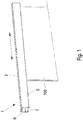
- FIG. 1 a sliding door system 1 according to the invention is shown schematically in a perspective illustration.
- the sliding door system 1 has a running rail 3 extending in the longitudinal direction, in which a door leaf with an in Figure 1 Not drive 4 shown is performed.
- the longitudinal direction is indicated by a double arrow.
- the running rail 3 has an essentially C-shaped cross section, the interior of the running rail 3 being concealed from the viewer via a panel 5.
- the running rail 3 forms a running track 7 for the running gear 4.
- a rail projection 6 which extends in the longitudinal direction of the running rail 3 and forms a securing device for the door leaf 100.
- the drive 4 consists of a carriage 9 which is fastened to a fastening device 11.
- the drive 4 is fastened to an upper edge 100a of the door leaf 100 via the fastening device 11.
- the fastening device has an upwardly projecting fastening section 12.
- the fastening section 12 has a recess 13 which has an opening 15 directed in the longitudinal direction of the running rail.
- the recess 13 has an approximately L-shaped course, so that in the in Figure 2b shown upright position of the door leaf 100, which corresponds to the position of the door leaf 100 in the suspended state, the recess 13 initially runs essentially in the longitudinal direction of the running rail 3 and then vertically upwards.
- the fastening part 23 of the carriage 9 which can be designed as a cylindrical axis, for example, can be inserted through the opening 15 into the recess 13 and pushed into the seat 21 so that the seat 21 rests against the fastening part 23.
- the carriage 9 can be fastened to the fastening section 12 by means of a fastening means 25 in the form of a nut. In the suspended state of the door leaf 100, the weight of the door leaf 100 is positively transmitted via the seat 21 to the carriage 9.
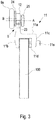
- FIG. 3 shows, in which a schematic view of the door leaf 100 is shown in the longitudinal direction of the running rail 3, the fastening device 11 is designed as a clamping device, with a main body 11a on both sides of the door leaf 100 forming jaws 11b, 11c.
- the clamping jaws 11b, 11c each have a thickening.
- a clamping plate 11d is arranged on one of the clamping jaws 11c on the side facing the door leaf 100, the clamping plate 11d being displaceable in the direction of the door leaf 100 by means of screws 11e to apply the clamping force.
- the carriage 9 has a roller 9a which is fastened to a roller block 24.
- the roller block 24 is connected to the fastening part 23, an eccentric arrangement of the roller 9a being formed, the roller axis B being arranged eccentrically to the central axis A of the fastening part 23.
- the fastening part 23 can be rotated in the seat 21, so that the position of the roller 9a can be changed in the vertical direction and thus a height adjustment of the door leaf 100 is made possible.
- the carriage 9 can be fastened again to the fastening device 11 by means of the fastening means 25.
- the opening 15 is arranged in the longitudinal direction of the running rail 3 facing a first side edge 100b of the door leaf, whereby the carriage 9 can advantageously be inserted into the opening 15 after being inserted into the running rail 3 and fastened to the fastening device 11.
- the fastening section 12 extends in the vertical direction adjoining the clamping jaw 11b.
- the main body 11a of the fastening device 11, the jaws 11b, 11c and the Has fastening portion 12, can be formed from an extruded profile, wherein the recess 13 can be milled out.
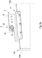
- FIG. 4 a second embodiment of the sliding door system according to the invention is shown schematically in a perspective view.
- the running rail 3 is in Fig. 4 shown without the aperture 5.
- the drive 4 arranged on the upper edge of the door leaf 100 has essentially the same structure as the drive described above.
- the sliding door system 1 differs from the previously described sliding door system in that a damper unit 27 with a pull-in function is arranged in the running rail 3 and interacts with a coupler 29 arranged on the carriage 4.
- the damper unit 27 has an engaging part 31 with which the coupler 29 engages in a latching manner.
- the door leaf 100 is first braked via the damper unit 27 and then driven into the end position in which it rests against the limiting device 33.
- the coupler 29 is designed to be adjustable in height.
- the coupler 29 has an adjustment section 29a which has an elongated hole extending in the vertical direction through which a screw 29b engages.
- the coupler 29 is fastened to the drive 4 via the screw. By loosening the screw, the adjustment section 29a and thus the coupler 29 can be adjusted in the vertical direction and fastened in the desired position via the screw 29b.
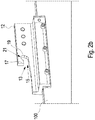
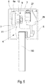
- FIG. 13 is a view of the embodiment of FIG Figure 4 shown in the longitudinal direction of the running rail 3 in the state inserted into the running rail 3.
- the running rail 3 can be made very compact, since the drive 4 is also very compact.
- the roller 9a is inserted into the track 7.
- the running rail 3 has a rail projection 6 which extends in the longitudinal direction of the running rail and which is located above the running track 7 and forms a safety device for the carriage 9 to be unhooked.
- the distance in the vertical direction between the rail projection 6 and the track 7 is selected so that the roller 9a can be pivoted into the track 3 when the carriage 9 is inserted.
- the carriage 9 is inserted in the detached state from the fastening device 11 and thus without the door leaf 100. After the carriage 9 has been inserted into the track 7, the carriage 9 can be moved in the longitudinal direction of the track 3 and after being inserted into the recess 13 the fastening device 11 are attached.
- the sliding door system 1 has a lock device 35.
- the lock device 35 has a bolt receptacle 37 which is arranged on the drive 4, as well as a bolt device 39 which is fastened in the running rail.
- the locking device 29 can, for example, form a structural unit together with a limiting device for limiting the travel path of the door leaf 100.
- the bolt receptacle has a receiving plate 37a which is fastened to the fastening section 12 of the fastening device 11.
- the bolt receptacle 37 is not shown for the sake of clarity.
- a receiving space 37b for a bolt 41 of the locking device 39 is formed on the opening 15 of the recess 13 via the bolt receptacle 37 in the direction facing away from the recess 13.
- the locking device 39 has a locking bar 41 which extends essentially in the longitudinal direction of the running rail 3 and has a hook-shaped section 41a at its end.
- the bolt 41 is pivotably mounted in a vertical plane extending in the longitudinal direction of the running rail 3.
- the bolt 41 has a pivot bearing 43 which engages the end of the bolt 41 opposite the hook-shaped section 41a.
- the pivot bearing 43 forms an axis of rotation for the bolt 41 running in the horizontal direction transversely to the longitudinal direction of the running rail 3.
- the bolt 41 also has a guide device 45. The pivoting movement of the bolt 41 is guided via the guide device 45 and limited upwards and downwards.
- the bolt 41 engages in the bolt receptacle 37.
- the hook-shaped section 41a and a further part of the bolt are located in the receiving space 37b of the bolt receptacle 37.
- the bolt receptacle 37 has a bolt actuator 47 and a bolt retainer 49, which in vertical Direction are arranged spaced from each other.
- the bolt device 39 also has a bolt holding device 51 which holds the bolt 41 in a retaining position in the locked state of the door leaf 100. In this position, opening of the door leaf 100 is prevented in that the bolt 41 interacts with the bolt retainer 49 via its hook-shaped section 41a.
- the bolt 41 In a state in which the bolt 41 has not yet been inserted into the bolt receptacle 37 and the bolt holding device 51 is deactivated, the bolt 41 is in a basic position into which the bolt 41 is due to a by the Automatic feedback force formed by gravity is moved.
- the basic position is in Fig. 7 shown.
- the bolt 41 is first inserted with the hook-shaped section 41a into the opening formed between the bolt actuator 47 and the bolt retainer 49.
- the bolt actuator 47 pushes against the bolt device 39 and, as the door leaf 100 continues to move towards the end position, pushes the bolt 41 against the automatic return force and regardless of whether the bolt retaining device 51 is activated or deactivated, upwards into the restraint position.
- the bolt holding device 51 is designed as a controllable magnet.
- the bolt 41 is made of a ferromagnetic material. When the magnet is actuated, it pulls the bolt 41 in a horizontal direction transversely to the longitudinal direction of the running rail 3, so that the bolt 41 rests partially on the magnet. As a result, a frictional connection is formed between the magnet and the bolt 41, so that the bolt cannot return to the basic position due to the automatic return force.
- the locking device 51 can be activated before the door leaf 100 is closed.
- the bolt 41 is then raised by the bolt actuator 47 from the basic position into the retaining position despite the holding force of the bolt retaining device 51 and then held in the retaining position by the bolt retaining device 51.
- the activation of the bolt holding device 51 before the door leaf 100 is closed has the advantage that the locking process of the door leaf 100 can be initiated regardless of its position, whereby it is ensured that the door leaf 100 is locked in its closed position after the next procedure.
- the bolt actuator 47 and the bolt retainer 49 are designed as projections which extend in the horizontal direction transversely to the longitudinal direction of the running rail 3 extend.
- the bolt actuator 47 and the bolt retainer 49 are designed symmetrically with respect to a horizontally extending center plane of the bolt retainer 37 extending in the longitudinal direction of the bolt retainer 37 and thus in the longitudinal direction of the running rail 3.
- the lock device 19 of the sliding door system 1 has the advantage that only the bolt holding device 51 has to be actuated for the locking process of the lock device 19, which pulls the bolt 41 and holds it in the retaining position.
- the bolt holding device therefore does not have to cause any movement of the bolt 41. Rather, the movement of the bolt 41 is caused by the movement of the door leaf 100 or the automatic return force.
- the complexity of the locking device 39 in terms of device technology is kept low.
Abstract
Schiebetürsystem (1) mit mindestens einer sich in eine Längsrichtung erstreckenden Laufschiene (3) und einem daran mit mindestens einem Laufwerk (4) geführten, vorzugsweise mit mindestens zwei Laufwerken geführten, Türflügel (100), wobei das mindestens eine Laufwerk (4) einen in der Laufschiene (3) mittels mindestens einer Laufrolle geführten Laufwagen (9) und eine mit dem Laufwagen (9) verbundene Befestigungsvorrichtung (11) aufweist, über die das Laufwerk (5) an einem oberen Rand (100a) des Türflügels (100) befestigt ist, wobei die Befestigungsvorrichtung einen nach oben abstehenden Befestigungsabschnitt aufweist, dadurch gekennzeichnet, dass die Befestigungsvorrichtung in dem Befestigungsabschnitt eine eine in Längsrichtung der Laufschiene gerichtete Öffnung aufweisende Aussparung zur Aufnahme eines Befestigungsteils des Laufwagens aufweist, wobei sich die Aussparung in Längsrichtung der Laufschiene und in vertikaler Richtung erstreckt, wobei ein in die Aussparung ragender Vorsprung gebildet ist und die Aussparung einen durch den Vorsprung und einen dem Vorsprung gegenüberliegenden Abschnitt des Befestigungsabschnitts begrenzten Sitz für das Befestigungsteil bildet, wobei das Befestigungsteil durch die Öffnung in die Aussparung einführbar und in den Sitz bewegbar ist, und wobei das Befestigungsteil des Laufwagens über mindestens ein Befestigungsmittel im an dem Sitz anliegender Position an der Befestigungsvorrichtung befestigbar ist.Sliding door system (1) with at least one running rail (3) extending in a longitudinal direction and a door leaf (100) guided thereon with at least one drive (4), preferably with at least two drives, the at least one drive (4) having an in the running rail (3) by means of at least one roller guided carriage (9) and a fastening device (11) connected to the carriage (9), via which the carriage (5) is fastened to an upper edge (100a) of the door leaf (100) , wherein the fastening device has an upwardly protruding fastening section, characterized in that the fastening device in the fastening section has a recess having an opening directed in the longitudinal direction of the running rail for receiving a fastening part of the carriage, the recess extending in the longitudinal direction of the running rail and in the vertical direction extends, with a protrusion protruding into the recess is formed and the recess forms a limited by the projection and a portion of the fastening portion opposite the projection seat for the fastening part, the fastening part being insertable through the opening into the recess and movable into the seat, and wherein the fastening part of the carriage via at least one Fastening means can be fastened to the fastening device in the position resting against the seat.
Description
Die vorliegende Erfindung betrifft ein Schiebetürsystem mit einer sich in eine Längsrichtung erstreckenden Laufschiene und einem daran mit mindestens einem Laufwerk geführten Türflügel, wobei das Laufwerk einen in der Laufschiene geführten Laufwagen und eine mit dem Laufwagen verbundene Befestigungsvorrichtung aufweist, über die das Laufwerk an einem oberen Rand des Türflügels befestigt ist.The present invention relates to a sliding door system with a running rail extending in a longitudinal direction and a door leaf guided thereon with at least one carriage, the carriage having a carriage guided in the running rail and a fastening device connected to the carriage, via which the carriage on an upper edge of the door leaf is attached.
Derartige Schiebetürsysteme sind allgemein bekannt. Über das Laufwerk wird der Türflügel von der Laufschiene getragen, sodass die Gewichtskraft des Türflügels über den Laufwagen auf die Laufschiene übertragen wird. Der Laufwagen rollt dabei mit einer oder mehreren Laufrollen in einer Laufbahn der Laufschiene ab.Such sliding door systems are generally known. The door leaf is carried by the running rail via the drive so that the weight of the door leaf is transferred to the running rail via the carriage. The carriage rolls with one or more rollers in a track of the running rail.
Es existieren Schiebetürsysteme, bei denen die Laufschiene eine Laufbahn für das Laufwerk aufweist, wobei der Laufwagen des Laufwerks an einer Seite eine oder mehrere Laufrollen aufweist, die in der Laufbahn geführt sind. Bei derartigen Schiebetürsystemen wird bei der Montage zumeist der Türflügel mit montiertem Laufwerk von der Längsseite der Laufschiene her in die Laufschiene eingehängt. Ein derartiges Schiebetürsystem ist beispielsweise aus
Es existieren ferner Schiebetürsysteme, bei denen die Laufwagen eines Laufwerks an beiden Seiten Laufrollen aufweisen, wobei die Laufschiene zwei parallele Laufbahnen aufweist, auf denen der Laufwagen mit den Laufrollen abrollt. Bei derartigen Schiebetürsystemen müssen die Laufwerke zumeist an einer Stirnseite der Laufschiene eingeschoben werden, da ein seitliches Einsetzen in die Laufschiene von der Längsseite der Laufschiene her nicht möglich ist. Derartige Laufwagen werden zumeist bei sehr großen und schweren Türflügeln verwendet. Dabei besteht bei der Montage der Türflügel häufig das Problem, dass die Türflügel aufgrund des sehr hohen Gewichts nur schwierig zu handhaben sind. Bei einer Art von Schiebetürsystemen werden die Türflügel von unten an den Laufwagen befestigt, wobei die Türflügel angehoben werden müssen. Insbesondere bei Glasschiebetürsystemen besteht jedoch das Problem, dass diese Türflügel besonders schwer sind und darüber hinaus sehr empfindlich, sodass ein leichtes Anstoßen einer Ecke des Türflügels bereits zu einer Beschädigung führen kann. Aus
Bei Schiebetürsystemen, bei denen bei der Montage der Türflügel mit montiertem Laufwerk von der Längsseite der Laufschiene her in die Laufschiene eigehängt wird, wird das Laufwerk häufig in die Laufbahn unterhalb einer Aushängesicherung, die durch einen Teil der Schiene gebildet wird, eingeschwenkt. Dazu muss der Türflügel von der Längsseite der Laufschiene her schräg angesetzt werden, wobei der Türflügel sich schräg von der Längsseite weg erstreckt. Um ein derartiges Einschwenken zu ermöglichen, muss jedoch in der Laufschiene ausreichend Platz für das Verschwenken des Laufwagens vorgesehen sein. Die Laufbahn hat somit zumeist einen relativ großen Abstand zu einer Wand, an der die Laufschiene befestigt ist, sodass auch der Türflügel, der in der Laufschiene geführt wird, einen relativ großen Wandabstand besitzt. Ein Einhängen des Türflügels in einer anderen Richtung, in der sich der Türflügel schräg in die von der Längsseite abgewandten Seite erstreckt, ist aufgrund der Wand, entlang der der Türflügel verläuft, nicht möglich.In the case of sliding door systems, in which the door leaf with the installed drive is hung from the longitudinal side of the running rail into the running rail during assembly, the running gear is often swiveled into the running track underneath a safety catch, which is formed by part of the rail. For this purpose, the door leaf must be placed at an angle from the long side of the running rail, the door leaf extending at an angle away from the long side. In order to enable such a pivoting, however, sufficient space must be provided in the running rail for the pivoting of the carriage. The track is therefore mostly at a relatively large distance from a wall to which the running rail is attached, so that the door leaf, which is guided in the running rail, also has a relatively large distance from the wall. A hanging of the door leaf in a different direction, in which the door leaf extends obliquely into the side facing away from the longitudinal side, is not possible because of the wall along which the door leaf runs.
Die vorbekannten Laufwerke sind jedoch zumeist relativ groß, um das hohe Gewicht von sehr großen Schiebetüren tragen zu können. Einen entsprechend großen Querschnitt müssen auch die Laufschienen aufweisen.However, the previously known drives are usually relatively large in order to be able to carry the heavy weight of very large sliding doors. The running rails must also have a correspondingly large cross-section.
Bei kleineren Schiebetüren oder Schiebetüren aus einem leichteren Glas sind die aus dem Stand der Technik bekannten sehr großen Laufwerke jedoch nicht unbedingt notwendig.In the case of smaller sliding doors or sliding doors made of a lighter glass, however, the very large drives known from the prior art are not absolutely necessary.
Es ist daher die Aufgabe der vorliegenden Erfindung, unter Beibehaltung der bequemen Montierbarkeit der aus dem Stand der Technik bekannte Schiebetürsysteme ein kompakteres Schiebetürsystem bereitzustellen.It is therefore the object of the present invention to provide a more compact sliding door system while maintaining the ease of assembly of the sliding door systems known from the prior art.
Das erfindungsgemäße Schiebetürsystem ist definiert durch die Merkmale des Anspruchs 1.The sliding door system according to the invention is defined by the features of
Bei dem erfindungsgemäßen Schiebetürsystem mit mindestens einer sich in eine Längsrichtung erstreckenden Laufschiene und einem daran mit mindestens einem Laufwerk geführten, vorzugsweise mit mindestens zwei Laufwerken geführten, Türflügel weist das mindestens eine Laufwerk einen in der Laufschiene mittels mindestens einer Laufrolle geführten Laufwagen und eine mit dem Laufwagen verbundene Befestigungsvorrichtung auf, wobei das mindestens eine Laufwerk an einem oberen Rand des Türflügels befestigt ist, wobei die Befestigungsvorrichtung einen nach oben abstehenden Befestigungsabschnitt aufweist. Die Erfindung ist dadurch gekennzeichnet, dass die Befestigungsvorrichtung in dem Befestigungsabschnitt eine, eine in Längsrichtung der Laufschiene gerichtete Öffnung aufweisende, Aussparung zur Aufnahme eines Befestigungsteils des Laufwagens aufweist, wobei sich die Aussparung in Längsrichtung der Laufschiene und in vertikaler Richtung erstreckt und wobei ein in die Aussparung ragender Vorsprung gebildet ist und die Aussparung einen durch den Vorsprung und einen dem Vorsprung gegenüberliegenden Abschnitt des Befestigungsabschnitts begrenzten Sitz für das Befestigungssteil bildet, wobei das Befestigungsteil des Laufwagens durch die Öffnung in die Aussparung einführbar und in den Sitz bewegbar ist und wobei das Befestigungsteil des Laufwagens über mindestens ein Befestigungsmittel in an dem Sitz anliegender Position an der Befestigungsvorrichtung befestigbar ist.In the sliding door system according to the invention with at least one running rail extending in a longitudinal direction and a door leaf guided thereon with at least one running gear, preferably guided with at least two running gears, the at least one running gear has a carriage guided in the running rail by means of at least one roller and one with the carriage connected fastening device, wherein the at least one drive is fastened to an upper edge of the door leaf, wherein the fastening device has an upwardly projecting fastening portion. The invention is characterized in that the fastening device in the fastening section has a recess, which has an opening directed in the longitudinal direction of the running rail, for receiving a fastening part of the carriage, the recess extending in the longitudinal direction of the running rail and in the vertical direction, and one in the Recess protruding projection is formed and the recess forms a limited by the projection and a portion of the fastening portion opposite the projection seat for the fastening part, wherein the fastening part of the carriage is insertable through the opening into the recess and movable into the seat and wherein the fastening part of the The carriage can be fastened to the fastening device via at least one fastening means in the position resting on the seat.
Das erfindungsgemäße Schiebetürsystem ermöglicht auf einfache Art und Weise, dass der Laufwagen zunächst in eine kompakt ausgestaltete Laufschiene eingesetzt werden kann und anschließend in Längsrichtung der Laufschiene verschoben wird, um mit der Befestigungsvorrichtung des Türflügels verbunden zu werden. Durch die in Längsrichtung der Laufschiene gerichtete Öffnung der Aussparung kann das Befestigungsteil des Laufwagens beim Verschieben des Laufwagens in der Laufschiene auf einfache Art und Weise in die Aussparung eingeführt werden und in den Sitz bewegt werden. Durch die Befestigung des Befestigungsteils des Laufwagens im an den Sitz anliegender Position kann die Gewichtskraft des Türflügels in vorteilhafter Weise über die Befestigungsvorrichtung auf den Laufwagen und somit auf die Laufschiene übertragen werden.The sliding door system according to the invention makes it possible, in a simple manner, that the carriage is initially inserted into a compactly designed running rail can be used and then moved in the longitudinal direction of the running rail to be connected to the fastening device of the door leaf. Through the opening of the recess directed in the longitudinal direction of the running rail, the fastening part of the carriage can be easily inserted into the recess and moved into the seat when the carriage is moved in the running rail. By fastening the fastening part of the carriage in the position resting against the seat, the weight of the door leaf can advantageously be transmitted via the fastening device to the carriage and thus to the running rail.
Der Vorsprung und der dem Vorsprung gegenüberliegende Abschnitt können zur Bildung des Sitzes verbunden sein, wobei beispielsweise der Sitz einen bogenförmigen Verlauf aufweisen kann. Grundsätzlich kann vorgesehen sein, dass die Form des Sitzes an die Form des Befestigungsteils angepasst ist.The projection and the section lying opposite the projection can be connected to form the seat, wherein, for example, the seat can have an arcuate shape. In principle, it can be provided that the shape of the seat is adapted to the shape of the fastening part.
In an dem Sitz anliegender Position des Befestigungsteils des Laufwagens können der Vorsprung und der dem Vorsprung gegenüberliegende Abschnitt des Befestigungsabschnitts eine Relativbewegung des Laufwagens und der Befestigungsvorrichtung in formschlüssiger Weise verhindern, indem der Vorsprung und der dem Vorsprung gegenüberliegende Abschnitt an dem Befestigungsteil anliegen.In the position of the fastening part of the carriage resting against the seat, the projection and the section of the fastening section opposite the projection can prevent a relative movement of the carriage and the fastening device in a form-fitting manner in that the projection and the section opposite the projection bear against the fastening part.
Die Aussparung kann grundsätzlich eine Form aufweisen, die einer L-Form entspricht. Im in der Laufschiene eingehängten Zustand des Türflügels erstreckt sich die Aussparung ausgehend von der Öffnung zunächst in Längsrichtung der Laufschiene und anschließend in vertikaler Richtung nach oben. In diesem Zustand bildet der nach oben, das heißt in vertikaler Richtung abstehende Befestigungsabschnitt durch den Vorsprung eine Art Hinterschneidung, hinter die der Laufwagen mit dem Befestigungsteil einhaken kann.The recess can basically have a shape that corresponds to an L-shape. When the door leaf is suspended in the running rail, the recess extends, starting from the opening, first in the longitudinal direction of the running rail and then upwards in the vertical direction. In this state, the fastening section protruding upwards, that is to say in the vertical direction, forms a type of undercut through the projection, behind which the carriage can hook with the fastening part.
Durch die erfindungsgemäße Anordnung wird darüber hinaus ermöglicht, dass das Befestigungsmittel nur eine geringe Kraft zur Befestigung des Laufwagens an der Befestigungsvorrichtung bereitstellen muss, da durch die Aussparung und den darin gebildeten Sitz eine formschlüssige Verbindung zwischen Laufwagen und Befestigungsvorrichtung gebildet ist, wobei die Gewichtskraft von der Befestigungsvorrichtung auf den Laufwagen über einen Formschluss übertragen wird.The arrangement according to the invention also enables the fastening means to provide only a small force for fastening the carriage to the fastening device, since the recess and the seat formed therein a form-fitting connection is formed between the carriage and the fastening device, the weight force being transmitted from the fastening device to the carriage via a form-fit connection.
Der Laufwagen wird in der Laufschiene geführt, indem mindestens eine Laufrolle auf mindestens einer Laufbahn der Laufschiene abrollen kann. Vorzugsweise ist vorgesehen, dass der Laufwagen nur einseitig eine oder mehrere Rollen aufweist, die in einer Laufbahn der Laufschiene geführt sind. Auf diese Weise ist eine besonders kompakte Ausgestaltung von Laufschiene und Laufwerk möglich. Die Laufschiene kann einen sich in Längsrichtung der Laufschiene erstreckenden Schienenvorsprung aufweisen, der eine Aushängesicherung für den Laufwagen bildet. Der Schienenvorsprung ist beispielsweise in vertikaler Richtung oberhalb der Laufbahn angeordnet. Der Abstand in vertikaler Richtung zwischen dem Schienenvorsprung und der Laufbahn kann so gewählt sein, dass die Laufrolle beim Einsetzen des Laufwagens ohne Türflügel unter dem Schienenvorsprung einschwenkbar ist. Auch kann der Schienenvorsprung derart nah an der Laufbahn angeordnet sein, dass im eingesetzten Zustand des Laufwagens lediglich ein Abstand von wenigen Millimetern oder sogar weniger als ein Millimeter zu der Laufrolle verbleibt, so dass ein Einschwenken des Laufwagens nicht möglich ist. In diesem Fall ist der Laufwagen von einem längsseitigen Ende der Laufschiene einzuführen.The carriage is guided in the running rail in that at least one roller can roll on at least one running track of the running rail. It is preferably provided that the carriage only has one or more rollers on one side, which are guided in a track of the running rail. In this way, a particularly compact design of the running rail and running gear is possible. The running rail can have a rail projection which extends in the longitudinal direction of the running rail and which forms a securing device for the carriage. The rail projection is arranged, for example, in the vertical direction above the track. The distance in the vertical direction between the rail projection and the track can be selected so that the roller can be swiveled in under the rail projection when the carriage is inserted without a door leaf. The rail projection can also be arranged so close to the track that when the carriage is in the inserted state, there is only a distance of a few millimeters or even less than one millimeter from the roller, so that the carriage cannot be swiveled in. In this case, the carriage is to be introduced from a longitudinal end of the running rail.
Im Rahmen der Erfindung wird unter dem Türflügel der plattenförmige Teil der Schiebetür/das Türblatt verstanden. Das Laufwerk ist ein Anbauteil an dem Türflügel und somit nicht als Teil des Türflügels zu verstehen.In the context of the invention, the door leaf is understood to mean the plate-shaped part of the sliding door / the door leaf. The drive is an add-on part on the door leaf and is therefore not to be understood as part of the door leaf.
Das erfindungsgemäße Schiebetürsystem ist besonders für Glastüren geeignet, bei denen der Türflügel aus Glas oder weitestgehend aus Glas besteht.The sliding door system according to the invention is particularly suitable for glass doors in which the door leaf consists of glass or largely of glass.
Vorzugsweise ist vorgesehen, dass das Befestigungsteil als sich in horizontaler Richtung quer zu der Längsrichtung der Laufschiene erstreckende zylindrische Achse ausgebildet ist, wobei die mindestens eine Laufrolle mit der zylindrischen Achse direkt oder über einen Rollenbock verbunden ist. Die Anordnung in horizontaler Richtung quer zu der Längsrichtung der Laufschiene ist dabei im eingehängten Zustand des Türflügels vorliegend.It is preferably provided that the fastening part is designed as a cylindrical axis extending in the horizontal direction transversely to the longitudinal direction of the running rail, the at least one roller being connected to the cylindrical axis directly or via a roller block. The order in the horizontal direction transversely to the longitudinal direction of the running rail is present in the suspended state of the door leaf.
Die Ausbildung des Befestigungsteils als zylindrische Achse ermöglicht eine konstruktiv einfache Ausgestaltung des Befestigungsteils, wobei das Befestigungsteil auf einfache Art und Weise in die Aussparung einführbar ist. Ferner ist bei der Anordnung des Befestigungsteils in dem Sitz dieses in vorteilhafter Weise unabhängig von seiner rotatorischen Ausrichtung befestigbar.The formation of the fastening part as a cylindrical axis enables a structurally simple design of the fastening part, with the fastening part being insertable into the recess in a simple manner. Furthermore, when the fastening part is arranged in the seat, it can advantageously be fastened independently of its rotational orientation.
Bei der Ausführungsform des erfindungsgemäßen Schiebetürsystems, bei dem die mindestens eine Laufrolle mit der zylindrischen Achse über den Rollenbock verbunden ist, kann eine Laufrollenachse exzentrisch zu einer Mittelachse der zylindrischen Achse angeordnet sein. Dadurch kann ermöglicht werden, dass durch eine Drehung des Befestigungsteils um die Mittelachse der zylindrischen Achse die Position der Laufrolle in vertikaler Richtung (im in der Laufschiene eingehängten Zustand des Türflügels) verstellbar ist, sodass eine Höhenverstelleinrichtung gebildet ist. Mit anderen Worten: Zur Höhenverstellung ist es lediglich notwendig, das Befestigungsteil zu drehen und in einer gewünschten Position mittels des mindestens einen Befestigungsmittels zu fixieren.In the embodiment of the sliding door system according to the invention, in which the at least one roller is connected to the cylindrical axis via the roller block, a roller axis can be arranged eccentrically to a central axis of the cylindrical axis. This makes it possible for the position of the roller to be adjusted in the vertical direction (when the door leaf is suspended in the running rail) by rotating the fastening part about the central axis of the cylindrical axis, so that a height adjustment device is formed. In other words: for height adjustment it is only necessary to rotate the fastening part and to fix it in a desired position by means of the at least one fastening means.
Dabei ist vorgesehen, dass die zylindrische Achse in einem gelösten Zustand in dem Sitz drehbar ist, wobei die Achse über das mindestens eine Befestigungsmittel in einer Drehposition in dem Sitz befestigbar ist.It is provided that the cylindrical axis can be rotated in a released state in the seat, the axis being able to be fastened in a rotational position in the seat via the at least one fastening means.
Das mindestens eine Befestigungsmittel kann eine Schraubmutter sein, die auf ein Gewinde der zylindrischen Achse schraubbar ist. Über die Schraubmutter kann eine Reibkraft mit einer Oberfläche des Befestigungsabschnitts hervorgerufen werden, die das Befestigungsteil fixiert. Auf diese Weise ist die Befestigung des Befestigungsteils auf einfache Art und Weise möglich.The at least one fastening means can be a screw nut which can be screwed onto a thread of the cylindrical shaft. A frictional force with a surface of the fastening section, which fixes the fastening part, can be produced via the screw nut. In this way, the fastening of the fastening part is possible in a simple manner.
Die Öffnung der Aussparung kann in Längsrichtung der Laufschiene an dem ersten Seitenrand des Türflügels zugewandt angeordnet sein.The opening of the recess can be arranged facing in the longitudinal direction of the running rail on the first side edge of the door leaf.
In einer bevorzugten Ausführungsform der Erfindung ist vorgesehen, dass die Aussparung in einem Mittelabschnitt des Befestigungsabschnitts angeordnet ist, wobei an die Öffnung in von der Aussparung abgewandter Richtung eine Riegelaufnahme zur Aufnahme eines Riegels einer an oder in der Laufschiene zumindest indirekt befestigten Riegelvorrichtung gebildet ist. Auf diese Weise ist das erfindungsgemäße Laufwerk in vorteilhafter Weise mit einer Riegelvorrichtung zur Verriegelung des Schiebetürsystems kombinierbar, wobei eine kompakte Ausgestaltung des Laufwerks und des Schiebetürsystems beibehalten wird.In a preferred embodiment of the invention it is provided that the recess is arranged in a central section of the fastening section, with a bolt receptacle for receiving a bolt of a bolt device fastened at least indirectly on or in the running rail being formed on the opening in the direction facing away from the recess. In this way, the drive according to the invention can advantageously be combined with a locking device for locking the sliding door system, with a compact design of the drive and the sliding door system being maintained.
Dabei ist vorzugsweise vorgesehen, dass die Riegelaufnahme eine seitlich an dem Befestigungsabschnitt angeordnete, sich parallel zu dem Befestigungsabschnitt erstreckende Aufnahmeplatte aufweist. Die Aufnahmeplatte ist in vorteilhafter Weise an der Befestigungsvorrichtung, beispielsweise auch nach Einhängen des Türflügels, befestigbar, wobei eine kompakte Ausgestaltung des Laufwerks beibehalten werden kann.It is preferably provided here that the latch receptacle has a receiving plate which is arranged laterally on the fastening section and extends parallel to the fastening section. The receiving plate can advantageously be fastened to the fastening device, for example also after the door leaf has been hung in, it being possible to maintain a compact design of the drive.
Dabei kann vorgesehen sein, dass die Aufnahmeplatte einen Riegelrückhalter aufweist. Der Riegelrückhalter kann im abgeschlossenen Zustand der Riegelvorrichtung den in die Riegelrücknahme aufgenommenen Riegel zurückhalten, sodass der Türflügel verriegelt ist.It can be provided that the receiving plate has a latch retainer. In the locked state of the locking device, the bolt retainer can hold back the bolt received in the bolt recess so that the door leaf is locked.
Die durch die Riegelvorrichtung gebildete Schlossvorrichtung, die in vorteilhafter Weise den Türflügel in einer geschlossenen Position abschließen kann, weist vorzugsweise folgende Ausgestaltung auf.The lock device formed by the locking device, which can advantageously lock the door leaf in a closed position, preferably has the following configuration.
Die Riegelaufnahme kann ferner einen Riegelbetätiger aufweisen, der von dem Riegelbetätiger beabstandet ist. Der Riegel ist beim Schließen des Türflügels zwischen dem Riegelbetätiger und dem Riegelrückhalter einführbar, wobei der Riegelbetätiger den Riegel beim Schließen des Türflügels entgegen einer selbsttätigen Rückführkraft in eine Rückhalteposition führt. In der Rückhalteposition hintergreift der Riegel den Riegelrückhalter, wobei die Riegelvorrichtung eine Riegelhaltevorrichtung aufweist, die den Riegel im Abschließzustand der Schlossvorrichtung in der Rückhalteposition hält.The bolt receptacle can furthermore have a bolt actuator which is spaced apart from the bolt actuator. The bolt can be inserted between the bolt actuator and the bolt retainer when the door is closed, the bolt actuator guiding the bolt into a retaining position when the door is closed against an automatic return force. In the retaining position, the bolt engages behind the bolt retainer, the bolt device having a bolt holding device which holds the bolt in the retaining position when the lock device is in the locked state.
Dadurch, dass der Riegelbetätiger den Riegel beim Schließen des Türflügels in die Rückhalteposition führt, ist kein separater Antrieb für den Riegel notwendig, wodurch der vorrichtungstechnische Aufwand für die Riegelvorrichtung reduziert ist. Der Antrieb des Riegels erfolgt über die Schließbewegung der Tür. Beispielsweise kann der Riegelbetätiger den Riegel in die Rückhalteposition drücken.Because the bolt actuator guides the bolt into the restraint position when the door leaf is closed, no separate drive is required for the bolt, which reduces the complexity of the bolt device. The bolt is driven by the closing movement of the door. For example, the latch operator can push the latch into the restraint position.
Bei dem erfindungsgemäßen Schiebetürsystem mit Schlossvorrichtung besteht die Besonderheit, dass der Riegel bei jedem Schließvorgang des Türflügels in die Rückhalteposition geführt wird. Ein Abschließen erfolgt jedoch erst durch die Betätigung der Riegelhaltevorrichtung, die den Riegel im Abschließzustand der Schlossvorrichtung in der Rückhalteposition hält. Dies hat den besonderen Vorteil, dass die Bewegung des Riegels in die Rückhalteposition und der eigentliche Abschließvorgang durch das Halten des Riegels über die Riegelhaltevorrichtung zwei unterschiedliche Vorgänge sind. Ein Öffnen des Türflügels ist dann möglich, wenn die Riegelhaltevorrichtung den Riegel nicht hält, so dass beim Öffnen des Türflügels der Riegel mittels der selbsttätigen Rückführkraft aus der Rückhalteposition in eine Grundposition zurückgeführt wird. Ohne weiteren Einfluss von außen befindet sich somit der Riegel nach dem Öffnen des Türflügels stets in der Grundposition, sodass ein darauffolgendes Schließen des Türflügels problemlos möglich ist. Es besteht somit nicht die Gefahr, dass der Riegel im geöffneten Zustand des Türflügels sich in seiner Rückhalteposition befindet und es zu einer unbeabsichtigten Kollision zwischen der Riegelaufnahme und dem Riegel kommen kann. Bei dem erfindungsgemäßen Schiebetürsystem mit Schlossvorrichtung kann die Riegelhaltevorrichtung auch derart ausgebildet sein, dass eine Aktivierung der Riegelhaltevorrichtung bereits vor dem Schließen des Türflügels erfolgen kann und der Riegel dann trotz Haltekraft der Riegelhaltevorrichtung durch den Riegelbetätiger aus der Grundposition in die Rückhalteposition angehoben und dann durch die Riegelhaltevorrichtung in der Rückhalteposition gehalten werden kann. Dies kann beispielsweise bei Ausführungen der Riegelhaltevorrichtung, bei denen die Riegelhaltevorrichtung den Riegel mittels reibschlüssiger Verbindung hält, möglich sein. Es sind auch Ausführungen der Riegelhaltevorrichtung möglich, bei denen die Riegelhaltevorrichtung den Riegel mittels Formschluss in der Rückhalteposition hält. Auch bei derartigen Ausführungen ist es möglich, die Riegelhaltevorrichtung bereits vor dem Schließen des Türflügels zu aktivieren, wobei der Riegel bei Schließen der Tür dann in die Riegelhaltevorrichtung einschnappen kann. Die Aktivierung der Riegelhaltevorrichtung bereits vor dem Schließen des Türflügels hat den Vorteil, dass der Abschließvorgang des Türflügels unabhängig von dessen Position eingeleitet werden kann, wobei sichergestellt ist, dass nach dem nächsten Verfahren in seine geschlossene Position der Türflügel abgeschlossen ist.In the case of the sliding door system according to the invention with a lock device, there is the special feature that the bolt is guided into the retention position with each closing process of the door leaf. However, locking only takes place when the bolt holding device is actuated, which holds the bolt in the retaining position in the locked state of the lock device. This has the particular advantage that the movement of the bolt into the retaining position and the actual locking process by holding the bolt over the bolt holding device are two different processes. The door sash can be opened when the bolt holding device does not hold the bolt, so that when the door sash is opened, the bolt is returned to a basic position by means of the automatic return force. Without any further influence from the outside, the bolt is always in the basic position after the door leaf has been opened, so that the door leaf can then be closed without any problems. There is therefore no risk that the bolt is in its retaining position when the door leaf is open and that an unintentional collision between the bolt receptacle and the bolt can occur. In the sliding door system according to the invention with a lock device, the bolt holding device can also be designed in such a way that the bolt holding device can be activated before the door leaf is closed and the bolt is then lifted from the basic position into the retaining position by the bolt operator despite the holding force of the bolt holding device and then by the bolt holding device can be held in the restraint position. This can be possible, for example, in designs of the bolt holding device in which the bolt holding device holds the bolt by means of a frictional connection. There are also versions of the bolt holding device possible in which the Bolt holding device holds the bolt in the retaining position by means of a form fit. With such designs it is also possible to activate the bolt holding device before the door leaf is closed, the bolt then being able to snap into the bolt holding device when the door is closed. The activation of the bolt holding device before the door leaf is closed has the advantage that the locking process of the door leaf can be initiated regardless of its position, whereby it is ensured that the door leaf is locked in its closed position after the next procedure.
Bei dem erfindungsgemäßen Schiebetürsystem mit Schlossvorrichtung kann der Riegel somit im geschlossenen Zustand des Türflügels in die Riegelaufnahme eingreifen und im Abschließzustand der Schlossvorrichtung hält die Riegelaufnahme den Riegel zurück. Dabei kann vorgesehen sein, dass in der Rückhalteposition der Riegel zwischen Riegelbetätiger und Riegelrückhalter angeordnet ist.In the sliding door system according to the invention with a lock device, the bolt can thus engage in the bolt receptacle in the closed state of the door leaf and in the locked state of the lock device the bolt receptacle holds the bolt back. It can be provided that in the restraint position the bolt is arranged between the bolt actuator and bolt retainer.
Die selbsttätige Rückführkraft kann beispielsweise über Schwerkraft erfolgen. Alternativ kann auch vorgesehen sein, dass an dem Riegel eine Federvorrichtung angeordnet ist, die den Riegel in Richtung der Grundposition zieht.The automatic return force can, for example, take place via gravity. Alternatively, it can also be provided that a spring device is arranged on the bolt, which pulls the bolt in the direction of the basic position.
Bei dem erfindungsgemäßen Schiebetürsystem mit Schlossvorrichtung kann vorgesehen sein, dass der Riegelbetätiger den Riegel beim Öffnen des Türflügels im aufgeschlossenen Zustand der Schlossvorrichtung aus der Rückhalteposition in die Grundposition führt, wobei die selbsttätige Rückführkraft den Riegel gegen den Riegelbetätiger drückt. Dadurch ist die Führung des Riegels beim Öffnen des Türflügels in vorteilhafter Weise möglich, da aufgrund der Rückführkraft der Riegel stets an dem Riegelbetätiger anliegt.In the sliding door system according to the invention with a lock device, it can be provided that the bolt operator guides the bolt from the restraint position into the basic position when the door leaf is opened in the unlocked state of the lock apparatus, with the automatic return force pressing the bolt against the bolt operator. As a result, the bolt can be guided in an advantageous manner when the door leaf is opened, since the bolt always rests against the bolt actuator due to the return force.
Es kann vorgesehen sein, dass die Riegelhaltevorrichtung elektrisch betätigbar ist, wobei bei einem Stromlos-Schalten der Riegelhaltevorrichtung diese den Riegel freigibt, so dass dann der Riegel aufgrund der selbstständigen Rückführkraft beim Öffnen des Türflügels in die Grundposition geführt werden kann. Beispielsweise bei einem Stromausfall kann somit der Türflügel des erfindungsgemäßen Schiebetürsystems stets geöffnet werden.It can be provided that the bolt holding device can be operated electrically, whereby when the bolt holding device is switched off, it releases the bolt, so that the bolt is then guided into the basic position due to the independent return force when the door leaf is opened can. In the event of a power failure, for example, the door leaf of the sliding door system according to the invention can therefore always be opened.
Vorzugsweise ist vorgesehen, dass der Riegel eine Drehlagerung aufweist und der Riegelbetätiger den Riegel in einer Verschwenkbewegung führt. Dadurch ist der Riegel in besonders vorteilhafter Weise in die Rückhalteposition, in der der Riegel den Riegelrückhalter hintergreift, führbar.It is preferably provided that the bolt has a pivot bearing and the bolt actuator guides the bolt in a pivoting movement. As a result, the bolt can be guided in a particularly advantageous manner into the retention position in which the bolt engages behind the bolt retainer.
Die Drehlagerung kann beispielsweise eine in horizontaler Richtung quer zu der Längsrichtung der Laufschiene angeordnete Drehachse aufweisen. Mit anderen Worten: Der Riegel kann in einer sich in Längsrichtung der Laufschiene erstreckenden vertikalen Ebene verschwenkt werden. In diesem Fall sind der Riegelbetätiger und der Riegelrückhalter in vertikaler Richtung beabstandet angeordnet, vorzugsweise übereinander angeordnet.The pivot bearing can, for example, have an axis of rotation arranged in the horizontal direction transversely to the longitudinal direction of the running rail. In other words: the bolt can be pivoted in a vertical plane extending in the longitudinal direction of the running rail. In this case, the bolt actuator and the bolt retainer are arranged spaced apart in the vertical direction, preferably arranged one above the other.
Vorzugsweise ist vorgesehen, dass die Riegelhaltevorrichtung als steuerbarer Magnet ausgebildet ist und der Riegel zumindest teilweise aus einem ferromagnetischen Material besteht. Bei der Erfindung kann somit in vorteilhafter Weise vorgesehen sein, dass die Riegelhaltevorrichtung den Riegel magnetisch in der Rückhalteposition hält. Dadurch ist die Schlossvorrichtung in vorteilhafter Weise elektrisch betreibbar, indem ein Elektromagnet verwendet wird. Es kann beispielsweise vorgesehen sein, dass der Magnet bei Betätigung den Riegel anzieht, bis der Riegel an dem Magneten anliegt. Dadurch ist der Riegel in besonders vorteilhafter Weise mittels der Riegelhaltevorrichtung in der Rückhalteposition haltbar. Durch das Anliegen des Riegels an dem Magneten wird eine Reibkraft zwischen Magnet und Riegel hervorgerufen, wodurch der Riegel in vorteilhafter Weise in der Rückhalteposition gehalten werden kann. Vorzugsweise ist vorgesehen, dass der Magnet den Riegel in einer Richtung quer zu der Ebene, in der der Riegel aus der Grundposition in die Rückhalteposition bewegbar ist, anzieht. Bei einem verschwenkbaren Riegel zieht der Magnet somit den Riegel quer zu der Verschwenkebene an. Somit wirkt der Magnet quer zu der Richtung, in der die selbsttätige Rückführkraft wirkt. Die zwischen dem Magneten und dem Riegel hervorgerufene Reibkraft wirkt somit der selbsttätigen Rückführkraft entgegen. Eine derartige Anordnung hat den besonderen Vorteil, dass beim Ausschalten des Magnets der Riegel in vorteilhafter Weise freigegeben wird.It is preferably provided that the bolt holding device is designed as a controllable magnet and the bolt consists at least partially of a ferromagnetic material. In the invention it can thus be provided in an advantageous manner that the bolt holding device holds the bolt magnetically in the retaining position. As a result, the lock device can advantageously be operated electrically by using an electromagnet. It can be provided, for example, that the magnet pulls the bolt when actuated until the bolt rests against the magnet. As a result, the bolt can be held in the retaining position in a particularly advantageous manner by means of the bolt holding device. The fact that the bolt rests against the magnet creates a frictional force between the magnet and bolt, whereby the bolt can advantageously be held in the retaining position. It is preferably provided that the magnet attracts the bolt in a direction transverse to the plane in which the bolt can be moved from the basic position into the retention position. In the case of a pivotable bolt, the magnet thus attracts the bolt transversely to the pivoting plane. The magnet thus acts transversely to the direction in which the automatic return force acts. The frictional force generated between the magnet and the bolt thus counteracts the automatic return force. Such an arrangement has its special The advantage is that when the magnet is switched off, the bolt is advantageously released.
Bei Ausführungsformen des erfindungsgemäßen Schiebetürsystems, bei denen die Riegelhaltevorrichtung als steuerbarer Magnet ausgebildet ist, kann in vorteilhafter Weise bereits eine Aktivierung der Riegelhaltevorrichtung vor dem Schließen des Türflügels erfolgen und der Riegel kann trotz Haltekraft der Riegelhaltevorrichtung durch den Riegelbetätiger aus der Grundposition in die Rückhalteposition angehoben werden.In embodiments of the sliding door system according to the invention in which the bolt holding device is designed as a controllable magnet, the bolt holding device can advantageously be activated before the door leaf is closed and the bolt can be lifted from the basic position into the retaining position by the bolt actuator despite the holding force of the bolt holding device .
In einer besonders bevorzugten Ausführungsform der Erfindung ist vorgesehen, dass die Riegelvorrichtung an einer Begrenzungsvorrichtung zur Begrenzung des Laufwegs des Türflügels befestigt ist. Die Riegelvorrichtung kann somit mit der Begrenzungsvorrichtung eine Baueinheit bilden. Dadurch wird die Montage des erfindungsgemäßen Schiebetürsystems vereinfacht, da lediglich die Kombination aus Begrenzungsvorrichtung und Riegelvorrichtung in der Laufschiene befestigt werden muss. Darüber hinaus werden Einbaufehler vermieden, da sichergestellt ist, dass sich der Riegel in Bezug auf die durch die Begrenzungsvorrichtung vorgegebene Endposition des Türflügels in der richtigen Position befindet.In a particularly preferred embodiment of the invention it is provided that the locking device is attached to a limiting device for limiting the path of travel of the door leaf. The locking device can thus form a structural unit with the limiting device. This simplifies the assembly of the sliding door system according to the invention, since only the combination of limiting device and locking device has to be fastened in the running rail. In addition, installation errors are avoided, since it is ensured that the bolt is in the correct position in relation to the end position of the door leaf predetermined by the limiting device.
Vorzugsweise ist vorgesehen, dass der Riegelbetätiger und der Riegelrückhalter als Vorsprünge ausgebildet sind, die sich vorzugsweise in horizontaler Richtung quer zu der Längsrichtung der Laufschiene erstrecken. Auf diese Weise sind der Riegelbetätiger und der Riegelrückhalter auf konstruktiv einfache Weise bereitstellbar.It is preferably provided that the bolt actuator and the bolt retainer are designed as projections which preferably extend in the horizontal direction transversely to the longitudinal direction of the running rail. In this way, the bolt actuator and the bolt retainer can be provided in a structurally simple manner.
Vorzugsweise ist vorgesehen, dass der Riegelbetätiger und der Riegelrückhalter symmetrisch zu einer Längsrichtung der Riegelaufnahme verlaufenden Mittelebene der Riegelaufnahme ausgebildet sind. Durch die symmetrische Anordnung kann die Aufnahmeplatte der Riegelaufnahme in vorteilhafter Weise an einem linksseitig oder rechtsseitig angeordneten Laufwerk verwendet werden, indem die Aufnahmeplatte entsprechend umgedreht wird.It is preferably provided that the bolt actuator and the bolt retainer are designed symmetrically to a central plane of the bolt retainer extending in the longitudinal direction of the bolt retainer. As a result of the symmetrical arrangement, the receiving plate of the bolt receptacle can advantageously be used on a drive arranged on the left or right-hand side by correspondingly turning the receiving plate.
Vorzugsweise ist vorgesehen, dass die Befestigungsvorrichtung als Klemmvorrichtung ausgebildet ist, wobei ein Hauptkörper der Begrenzungsvorrichtung beidseitig des Türflügels Klemmbacken bildet, wobei an einer Klemmbacke eine in Richtung auf den Türflügel verschiebbare Klemmplatte angeordnet ist. Eine derartige Befestigungsvorrichtung lässt sich in besonders vorteilhafter Weise an einem Türflügel, insbesondere an einem Türflügel aus Glas, auch bei unterschiedlichen Materialstärken des Glases, befestigen.It is preferably provided that the fastening device is designed as a clamping device, a main body of the limiting device forming clamping jaws on both sides of the door leaf, a clamping plate being arranged on one clamping jaw, which can be displaced in the direction of the door leaf. A fastening device of this type can be fastened in a particularly advantageous manner to a door leaf, in particular to a door leaf made of glass, even with different material thicknesses of the glass.
Vorzugsweise ist vorgesehen, dass der Hauptkörper ein Strangpressprofil, vorzugsweise ein Aluminiumstrangpressprofil, ist. Auf diese Weise lässt sich der Hauptkörper und somit die Befestigungsvorrichtung auf einfache Art und Weise herstellen.It is preferably provided that the main body is an extruded profile, preferably an extruded aluminum profile. In this way, the main body and thus the fastening device can be produced in a simple manner.
Die Klemmplatte kann beispielweise aus Blech sein und lässt sich über Schrauben in Richtung des Türflügels zur Bereitstellung der Klemmkraft verschieben. Bei dem Hauptkörper aus einem Strangpressprofil kann die Aussparung mittels eines Fräsvorgangs hergestellt werden.The clamping plate can be made of sheet metal, for example, and can be moved in the direction of the door leaf by means of screws to provide the clamping force. In the case of the main body made from an extruded profile, the recess can be produced by means of a milling process.
Vorzugsweise ist vorgesehen, dass die Klemmbacken jeweils eine Verdickung aufweisen. Auf diese Weise wird eine höhere Stabilität der Klemmbacke insbesondere in dem Übergangsbereich zu dem übrigen Teil des Hauptkörpers ermöglicht.It is preferably provided that the clamping jaws each have a thickening. In this way, greater stability of the clamping jaw is made possible, in particular in the transition area to the remaining part of the main body.
Es kann vorgesehen sein, dass der Befestigungsabschnitt sich in vertikaler Richtung an eine der Klemmbacken anschließt. Die vertikale Richtung bezieht sich auf den eingehängten Zustand des Türflügels.It can be provided that the fastening section adjoins one of the clamping jaws in the vertical direction. The vertical direction refers to the hinged state of the door leaf.
In einer bevorzugten Ausführung der Erfindung ist vorgesehen, dass eine in der Laufschiene angeordnete Dämpfereinheit mit Einzugsfunktion vorgesehen ist und an dem Laufwerk ein Koppler angeordnet ist, der mit einem Angreifteil der Dämpfereinheit rastend zusammengreift, wobei die Dämpfereinheit beim Verfahren in Richtung einer Endstellung den Türflügel zunächst abbremst und anschließend in die Endstellung treibt, und wobei der Koppler in vertikaler Richtung verstellbar ist. Die vertikale Richtung bezieht sich auf den eingehängten Zustand des Türflügels. Mittels der Dämpfereinheit mit Einzugsfunktion kann in vorteilhafter Weise ermöglicht werden, dass der Türflügel beim Verschieben in die Endstellung zunächst frei verfahren werden kann, dann von der Dämpfereinheit mit Einzugsfunktion abgebremst wird, wobei der Koppler mit einem Angreifteil rastend zusammengreift und schließlich von der Dämpfereinheit mit Einzugsfunktion sanft in seine Endstellung getrieben wird. Durch die Verstellung des Kopplers in vertikaler Richtung kann das aus Dämpfereinheit und Koppler gebildete System in vorteilhafter Weise an den mittels der Höhenverstellung eingestellten Türflügel angepasst werden.In a preferred embodiment of the invention it is provided that a damper unit with a pull-in function arranged in the running rail is provided and a coupler is arranged on the drive which engages with an engaging part of the damper unit in a latching manner, the damper unit initially moving the door leaf towards an end position brakes and then drives into the end position, and wherein the coupler is adjustable in the vertical direction. The vertical direction refers to the hooked one State of the door leaf. By means of the damper unit with pull-in function, it can advantageously be made possible that the door leaf can initially be moved freely when it is moved into the end position, then is braked by the damper unit with pull-in function, the coupler engaging with an engaging part and finally by the damper unit with pull-in function is gently driven into its end position. By adjusting the coupler in the vertical direction, the system formed from the damper unit and coupler can advantageously be adapted to the door leaf adjusted by means of the height adjustment.
Es kann vorgesehen sein, dass die Dämpfereinheit an der Begrenzungsvorrichtung zur Begrenzung des Laufwegs des Türflügels befestigt bzw. festgelegt ist. Dadurch können Dämpfereinheit und Begrenzungsvorrichtung eine Baueinheit bilden, sodass die Montage vereinfacht ist und Einbaufehler vermieden werden. Die Dämpfereinheit kann beispielsweise über einen Passstift an der Begrenzungsvorrichtung festgelegt sein. Bei einer Ausführungsform des Schiebetürsystems mit Schlossvorrichtung kann die Baueinheit aus Dämpfereinheit, Begrenzungsvorrichtung und Riegelvorrichtung bestehen.It can be provided that the damper unit is attached or fixed to the delimitation device for delimiting the path of travel of the door leaf. As a result, the damper unit and the limiting device can form a structural unit so that assembly is simplified and installation errors are avoided. The damper unit can be fixed on the limiting device, for example, by means of a dowel pin. In one embodiment of the sliding door system with a lock device, the structural unit can consist of a damper unit, a limiting device and a locking device.
Der Koppler kann einen Befestigungsabschnitt mit einem sich in vertikaler Richtung erstreckenden Langloch aufweisen, durch das eine Schraube greift. Die vertikale Richtung bezieht sich auf den eingehängten Zustand des Türflügels. Auf diese Weise ist eine Verstellung des Kopplers in vertikaler Richtung auf einfache Art und Weise möglich.The coupler can have a fastening section with an elongated hole which extends in the vertical direction and through which a screw engages. The vertical direction refers to the hinged state of the door leaf. In this way, an adjustment of the coupler in the vertical direction is possible in a simple manner.
Im Rahmen der Erfindung sind Richtungsangaben, wie z.B. oben, horizontal, vertikal usw., - sofern nicht anders beschrieben - stets unter der Annahme angegeben, dass sich der Türflügel im in die Laufschiene eingehängten Zustand befindet.In the context of the invention, directions, such as above, horizontal, vertical, etc., - unless otherwise described - are always given under the assumption that the door leaf is in the state suspended in the running rail.
Im Folgenden werden unter Bezugnahme auf die nachfolgenden Figuren Ausführungsbeispiele der Erfindung näher erläutert.In the following, exemplary embodiments of the invention are explained in more detail with reference to the following figures.
Es zeigen
Figur 1- eine schematische, perspektivische Darstellung eines ersten Ausführungsbeispiels des erfindungsgemäßen Schiebetürsystems,
- Figur 2a, 2b
- schematische, perspektivische Darstellungen des Türflügels mit an dem Türflügel befestigten Laufwerk des ersten Ausführungsbeispiels des erfindungsgemäßen Schiebetürsystems,
Figur 3- eine schematische Draufsicht auf den Türflügel der
Fign. 2a ,2b in Längsrichtung der Laufschiene, Figur 4- eine schematische, perspektivische Darstellung eines Türflügels mit an dem Türflügel befestigten Laufwerk eines zweiten Ausführungsbeispiels des erfindungsgemäßen Schiebetürsystems,
Figur 5- eine schematische Draufsicht auf den Türflügel der
Fig 3 in Längsrichtung der Laufschiene, Figur 6- eine schematische Seitenansicht eines Türflügels mit befestigtem Laufwerk sowie Begrenzungsvorrichtung eines dritten Ausführungsbeispiels eines erfindungsgemäßen Schiebetürsystems und
Figur 7- eine weitere schematische Draufsicht des in
Figur 6
- Figure 1
- a schematic, perspective illustration of a first embodiment of the sliding door system according to the invention,
- Figure 2a, 2b
- schematic, perspective representations of the door leaf with the drive of the first exemplary embodiment of the sliding door system according to the invention attached to the door leaf,
- Figure 3
- a schematic plan view of the door leaf of
Figs. 2a ,2 B in the longitudinal direction of the track, - Figure 4
- a schematic, perspective illustration of a door leaf with a drive attached to the door leaf of a second embodiment of the sliding door system according to the invention,
- Figure 5
- a schematic plan view of the door leaf of
Fig 3 in the longitudinal direction of the track, - Figure 6
- a schematic side view of a door leaf with attached drive and limiting device of a third embodiment of a sliding door system according to the invention and
- Figure 7
- a further schematic plan view of the in
Figure 6 illustrated door leaf.
In
Das erfindungsgemäße Schiebetürsystem 1 weist eine sich in Längsrichtung erstreckende Laufschiene 3 auf, in der ein Türflügel mit einem in
Die Laufschiene 3 bildet eine Laufbahn 7 für das Laufwerk 4. Oberhalb der Laufbahn 7 ist ein Schienenvorsprung 6 angeordnet, der sich in Längsrichtung der Laufschiene 3 erstreckt und eine Aushängesicherung für den Türflügel 100 bildet.The running
Das Laufwerk 4 besteht aus einem Laufwagen 9, der an einer Befestigungsvorrichtung 11 befestigt ist. Über die Befestigungsvorrichtung 11 ist das Laufwerk 4 an einem oberen Rand 100a des Türflügels 100 befestigt.The
Die Befestigungsvorrichtung weist einen nach oben abstehenden Befestigungsabschnitt 12 auf. Wie am besten aus
Dadurch ist ein Vorsprung 17 gebildet, der in die Aussparung 13 ragt. Der Vorsprung 17 und ein dem Vorsprung 17 gegenüberliegender Abschnitt 19 des Befestigungsabschnitts 12 begrenzen einen Sitz 21 für ein Befestigungsteil 23 des Laufwagens 9. Das Befestigungsteil 23 des Laufwagens 9, das beispielsweise als zylindrische Achse ausgebildet sein kann, kann durch die Öffnung 15 in die Aussparung 13 eingeführt werden und in den Sitz 21 geschoben werden, sodass der Sitz 21 an dem Befestigungsteil 23 anliegt. Der Laufwagen 9 kann dabei mittels eines Befestigungsmittels 25 in Form einer Mutter an dem Befestigungsabschnitt 12 befestigt werden. Im eingehängten Zustand des Türflügels 100 wird die Gewichtskraft des Türflügels 100 formschlüssig über den Sitz 21 auf den Laufwagen 9 übertragen.This forms a
Wie am besten aus
An einer der Klemmbacken 11c ist eine Klemmplatte 11d auf der dem Türflügel 100 zugewandten Seite angeordnet, wobei die Klemmplatte 11d mittels Schrauben 11e zur Aufbringung der Klemmkraft in Richtung zu dem Türflügel 100 verschiebbar ist.A clamping
Der Laufwagen 9 weist eine Laufrolle 9a auf, die an einem Rollenbock 24 befestigt ist. Der Rollenbock 24 ist mit dem Befestigungssteil 23 verbunden, wobei eine exzentrische Anordnung der Laufrolle 9a gebildet ist, wobei die Laufrollenachse B exzentrisch zu der Mittelachse A des Befestigungsteils 23 angeordnet ist. Durch ein Lösen des Befestigungsmittels 25 kann das Befestigungsteil 23 in dem Sitz 21 gedreht werden, sodass sich die Position der Laufrolle 9a in vertikaler Richtung ändern lässt und somit eine Höhenverstellung des Türflügels 100 ermöglicht wird. Nach der gewünschten Einstellung der Laufrolle 9a kann der Laufwagen 9 mittels des Befestigungsmittels 25 wieder an der Befestigungsvorrichtung 11 befestigt werden.The
Wie aus
Wie aus
In
Die Laufschiene 3 ist in
Die Dämpfereinheit 27 bildet zusammen mit einer Begrenzungsvorrichtung 33, die den Laufweg des Türflügels 100 begrenzt, eine Baueinheit, sodass die Dämpfereinheit 27 und die Begrenzungsvorrichtung 33 gemeinsam in der Laufschiene 3 befestigt werden können. Über die Dämpfereinheit 27 wird der Türflügel 100 beim Verfahren in Richtung seiner Endstellung zunächst abgebremst und anschließend in die Endstellung, in der er an der Begrenzungsvorrichtung 33 anliegt, getrieben.The
Der Koppler 29 ist höhenverstellbar ausgestaltet. Hierzu weist der Koppler 29 einen Verstellabschnitt 29a auf, der ein sich in vertikaler Richtung erstreckendes Langloch aufweist, durch das eine Schraube 29b greift. Über die Schraube wird der Koppler 29 an dem Laufwerk 4 befestigt. Durch ein Lösen der Schraube lässt sich der Verstellabschnitt 29a und somit der Koppler 29 in vertikaler Richtung verstellen und über die Schraube 29b in der gewünschten Stellung befestigen.The
In
In
Die Laufrolle 9a ist in die Laufbahn 7 eingesetzt. Die Laufschiene 3 weist einen sich in Längsrichtung der Laufschiene erstreckenden Schienenvorsprung 6 auf, der sich oberhalb der Laufbahn 7 befindet und eine Aushängesicherung für den Laufwagen 9 bildet. Der Abstand in vertikaler Richtung zwischen dem Schienenvorsprung 6 und der Laufbahn 7 ist dabei so gewählt, dass die Laufrolle 9a beim Einsetzen des Laufwagens 9 in die Laufschiene 3 eingeschwenkt werden kann. Das Einsetzen des Laufwagens 9 erfolgt im von der Befestigungsvorrichtung 11 gelösten Zustand und somit ohne den Türflügel 100. Nach dem Einsetzen des Laufwagens 9 in die Laufbahn 7 kann der Laufwagen 9 in Längsrichtung der Laufschiene 3 bewegt werden und nach dem Einführen in die Aussparung 13 an der Befestigungsvorrichtung 11 befestigt werden.The
In den
Die Riegelaufnahme weist eine Aufnahmeplatte 37a auf, die an dem Befestigungsabschnitt 12 der Befestigungsvorrichtung 11 befestigt ist. In
Über die Riegelaufnahme 37 wird an die Öffnung 15 der Aussparung 13 in von der Aussparung 13 abgewandter Richtung ein Aufnahmeraum 37b für einen Riegel 41 der Riegelvorrichtung 39 gebildet.A receiving
Die Riegelvorrichtung 39 weist einen Riegel 41 auf, der sich im Wesentlichen in Längsrichtung der Laufschiene 3 erstreckt und an seinem Ende einen hakenförmigen Abschnitt 41a aufweist.The locking
Der Riegel 41 ist in einer sich in Längsrichtung der Laufschiene 3 erstreckenden vertikalen Ebene verschwenkbar gelagert. Dazu weist der Riegel 41 eine Drehlagerung 43 auf, die an dem dem hakenförmigen Abschnitt 41a gegenüberliegenden Ende des Riegels 41 angreift. Die Drehlagerung 43 bildet eine sich in horizontaler Richtung quer zu der Längsrichtung der Laufschiene 3 verlaufende Drehachse für den Riegel 41. Ferner weist der Riegel 41 eine Führungseinrichtung 45 auf. Über die Führungseinrichtung 45 wird die Verschwenkbewegung des Riegels 41 geführt und nach oben und nach unten hin begrenzt.The
Wie aus
In einem Zustand, in dem der Riegel 41 noch nicht in die Riegelaufnahme 37 eingeführt und die Riegelhaltevorrichtung 51 deaktiviert ist, befindet sich der Riegel 41 in einer Grundposition, in die der Riegel 41 aufgrund einer durch die Schwerkraft gebildeten selbsttätigen Rückführkraft bewegt wird. Die Grundposition ist in
Bei der Schließbewegung des Türflügels 100 wird der Riegel 41 zunächst mit dem hakenförmigen Abschnitt 41a in die zwischen dem Riegelbetätiger 47 und dem Riegelrückhalter 49 gebildete Öffnung eingeführt. Der Riegelbetätiger 47 stößt dabei gegen die Riegelvorrichtung 39 und drückt bei der weiteren Bewegung des Türflügels 100 in Richtung der Endstellung den Riegel 41 entgegen der selbsttätigen Rückführkraft und unabhängig davon, ob die Riegelhaltevorrichtung 51 aktiviert oder deaktiviert ist, nach oben in die Rückhalteposition.During the closing movement of the
Die Riegelhaltevorrichtung 51 ist als steuerbarer Magnet ausgebildet. Der Riegel 41 ist aus einem ferromagnetischen Material gefertigt. Bei der Betätigung des Magneten zieht dieser den Riegel 41 in horizontaler Richtung quer zur Längsrichtung der Laufschiene 3 an, sodass der Riegel 41 teilweise an dem Magneten anliegt. Dadurch wird zwischen dem Magneten und dem Riegel 41 eine reibschlüssige Verbindung gebildet, sodass der Riegel nicht durch die selbsttätige Rückführkraft in die Grundposition zurückkehren kann.The bolt holding device 51 is designed as a controllable magnet. The
Bei dem erfindungsgemäßen Schiebetürsystem 1 kann eine Aktivierung der Riegelhaltevorrichtung 51 bereits vor dem Schließen des Türflügels 100 erfolgen. Der Riegel 41 wird dann beim Schließen des Türflügels 100 trotz Haltekraft der Riegelhaltevorrichtung 51 durch den Riegelbetätiger 47 aus der Grundposition in die Rückhalteposition angehoben und dann durch die Riegelhaltevorrichtung 51 in der Rückhalteposition gehalten.In the sliding
Die Aktivierung der Riegelhaltevorrichtung 51 bereits vor dem Schließen des Türflügels 100 hat den Vorteil, dass der Abschließvorgang des Türflügels 100 unabhängig von dessen Position eingeleitet werden kann, wobei sichergestellt ist, dass nach dem nächsten Verfahren in seine geschlossene Position der Türflügel 100 abgeschlossen ist.The activation of the bolt holding device 51 before the
Der Riegelbetätiger 47 und der Riegelrückhalter 49 sind als Vorsprünge ausgebildet, die sich in horizontaler Richtung quer zur Längsrichtung der Laufschiene 3 erstrecken. Der Riegelbetätiger 47 und der Riegelrückhalter 49 sind gegenüber einer in Längsrichtung der Riegelaufnahme 37 und somit in Längsrichtung der Laufschiene 3 erstreckenden horizontal verlaufenden Mittelebene der Riegelaufnahme 37 symmetrisch ausgebildet.The
Die Schlossvorrichtung 19 des erfindungsgemäßen Schiebetürsystems 1 hat den Vorteil, dass für den Abschließvorgang der Schlossvorrichtung 19 lediglich die Riegelhaltevorrichtung 51 betätigt werden muss, die den Riegel 41 anzieht und in der Rückhalteposition hält. Die Riegelhaltevorrichtung muss somit keine Bewegung des Riegels 41 hervorrufen. Vielmehr wird die Bewegung des Riegels 41 durch die Bewegung des Türflügels 100 bzw. die selbsttätige Rückführkraft hervorgerufen. Dadurch ist der vorrichtungstechnische Aufwand der Riegelvorrichtung 39 geringgehalten.The
- 11
- SchiebetürsystemSliding door system
- 33
- LaufschieneRunning track
- 44th
- Laufwerkdrive
- 55
- Blendecover
- 66th
- SchienenvorsprungRail protrusion
- 77th
- Laufbahncareer
- 99
- LaufwagenCarriage
- 9a9a
- LaufrolleCaster
- 1111
- BefestigungsvorrichtungFastening device
- 11a11a
- HauptkörperMain body
- 11b11b
- KlemmbackeJaw
- 11c11c
- KlemmbackenJaws
- 11d11d
- KlemmplatteClamping plate
- 11e11e
- SchraubenScrews
- 1212th
- BefestigungsabschnittFastening section
- 1313th
- AussparungRecess
- 1515th
- Öffnungopening
- 1717th
- Vorsprunghead Start
- 1919th
- gegenüberliegender Abschnittopposite section
- 2121
- SitzSeat
- 2323
- BefestigungsteilFastening part
- 2424
- RollenbockRoller block
- 2525th
- BefestigungsmittelFasteners
- 2727
- DämpfereinheitDamper unit
- 2929
- KopplerCoupler
- 29a29a
- VerstellabschnittAdjustment section
- 29b29b
- Schraubescrew
- 3131
- AngreifteilAttack part
- 3333
- BegrenzungsvorrichtungLimiting device
- 3535
- SchlossvorrichtungLock device
- 3737
- RiegelaufnahmeBolt mount
- 37a37a
- AufnahmeplatteMounting plate
- 37b37b
- Raumroom
- 3939
- RiegelvorrichtungLocking device
- 4141
- Riegelbars
- 41a41a
- hakenförmiger Abschnitthook-shaped section
- 4343
- DrehlagerungPivot bearing
- 4545
- FührungseinrichtungGuide device
- 4747
- RiegelbetätigerLatch actuator
- 4949
- RiegelrückhalterLatch retainer
- 5151
- RiegelhaltevorrichtungBolt holding device
- 100100
- TürflügelDoor leaf
- 100a100a
- oberer Randupper edge
- 100b100b
- erster Seitenrandfirst margin
- AA.
- MittelachseCentral axis
- BB.
- LaufrollenachseRoller axis
Claims (15)
dadurch gekennzeichnet,
dass die Befestigungsvorrichtung (11) in dem Befestigungsabschnitt (12) eine, eine in Längsrichtung der Laufschiene gerichtete Öffnung (15) aufweisende, Aussparung (13) zur Aufnahme eines Befestigungsteils (23) des Laufwagens (9) aufweist, wobei sich die Aussparung (13) in Längsrichtung der Laufschiene (3) und in vertikaler Richtung erstreckt, wobei ein in die Aussparung (13) ragender Vorsprung (17) gebildet ist und die Aussparung (13) einen durch den Vorsprung (17) und einen dem Vorsprung (17) gegenüberliegenden Abschnitt (19) des Befestigungsabschnitts (12) begrenzten Sitz (21) für das Befestigungsteil (23) bildet, wobei das Befestigungsteil (23) durch die Öffnung (15) in die Aussparung (13) einführbar und in den Sitz (21) bewegbar ist, und wobei das Befestigungsteil (23) des Laufwagens (9) über mindestens ein Befestigungsmittel (25) in an dem Sitz (23) anliegender Position an der Befestigungsvorrichtung (11) befestigbar ist.Sliding door system (1) with at least one running rail (3) extending in a longitudinal direction and a door leaf (100) guided thereon with at least one drive (4), preferably with at least two drives, the at least one drive (4) having an in the running rail (3) has a carriage (9) guided by at least one roller and a fastening device (11) connected to the carriage (9), via which the carriage (5) is fastened to an upper edge (100a) of the door leaf (100) , wherein the fastening device (11) has an upwardly projecting fastening section (12),
characterized,
that the fastening device (11) in the fastening section (12) has a recess (13) having an opening (15) directed in the longitudinal direction of the running rail for receiving a fastening part (23) of the carriage (9), the recess (13 ) extends in the longitudinal direction of the running rail (3) and in the vertical direction, a projection (17) protruding into the recess (13) being formed and the recess (13) being formed by one through the projection (17) and one opposite the projection (17) Section (19) of the fastening section (12) forms a limited seat (21) for the fastening part (23), the fastening part (23) being insertable through the opening (15) into the recess (13) and movable into the seat (21) and wherein the fastening part (23) of the carriage (9) can be fastened to the fastening device (11) via at least one fastening means (25) in the position adjacent to the seat (23).
die Riegelaufnahme (37) eine seitlich an dem Befestigungsabschnitt (2) angeordnete, sich parallel zu dem Befestigungsabschnitt (12) erstreckende Aufnahmeplatte (37a) aufweist.Sliding door system according to one of Claims 1 to 6, characterized in that the recess (13) is arranged in a central section of the fastening section (12), with a bolt receptacle (37) attached to the opening (15) in the direction facing away from the recess (13). for receiving a bolt (41) of a bolt device (39) fastened at least indirectly on or in the running rail (3), preferably.
the latch receptacle (37) has a receiving plate (37a) which is arranged laterally on the fastening section (2) and extends parallel to the fastening section (12).
die Dämpfereinheit (27) an der Begrenzungsvorrichtung (33) zur Begrenzung des Laufwegs des Türflügels (100) festgelegt istSliding door system according to one of Claims 1 to 13, characterized by a damper unit (27) with a pull-in function arranged in the running rail (3) and a coupler (29) arranged on the carriage (4) which is connected to an engaging part (31) of the damper unit (27 ) engages in a latching manner, the damper unit (27) pushing the door leaf (100) when moving in the direction of an end position initially brakes and then drives into the end position, the coupler (29) being adjustable in the vertical direction, preferably.
the damper unit (27) is fixed to the limiting device (33) for limiting the path of travel of the door leaf (100)
Applications Claiming Priority (1)
| Application Number | Priority Date | Filing Date | Title |
|---|---|---|---|
| DE102020100657.8A DE102020100657A1 (en) | 2020-01-14 | 2020-01-14 | Sliding door system |
Publications (2)
| Publication Number | Publication Date |
|---|---|
| EP3851621A2 true EP3851621A2 (en) | 2021-07-21 |
| EP3851621A3 EP3851621A3 (en) | 2021-09-22 |
Family
ID=73554290
Family Applications (1)
| Application Number | Title | Priority Date | Filing Date |
|---|---|---|---|
| EP20209433.0A Pending EP3851621A3 (en) | 2020-01-14 | 2020-11-24 | Sliding door system |
Country Status (2)
| Country | Link |
|---|---|
| EP (1) | EP3851621A3 (en) |
| DE (1) | DE102020100657A1 (en) |
Families Citing this family (1)
| Publication number | Priority date | Publication date | Assignee | Title |
|---|---|---|---|---|
| US11891847B2 (en) * | 2020-04-30 | 2024-02-06 | Dirtt Environmental Solutions Ltd. | Compact sliding door system with soft-close and locking functionality |
Citations (2)
| Publication number | Priority date | Publication date | Assignee | Title |
|---|---|---|---|---|
| DE102011012286A1 (en) | 2011-02-24 | 2012-08-30 | Gebr. Willach Gmbh | Drive for a sliding door |
| DE102016202774A1 (en) | 2016-02-23 | 2017-08-24 | Gebr. Willach Gmbh | sliding door system |
Family Cites Families (8)
| Publication number | Priority date | Publication date | Assignee | Title |
|---|---|---|---|---|
| US904393A (en) * | 1908-04-01 | 1908-11-17 | Edson G Worden | Door-hanger. |
| AU438982B2 (en) * | 1969-07-16 | 1973-08-07 | Vincent Anthony Silvio | Suspending means for sliding doors and the like |
| JP3878526B2 (en) * | 2002-08-20 | 2007-02-07 | 株式会社Skb | runner |
| DE10354313A1 (en) * | 2003-11-20 | 2005-06-30 | Bernhard Feigl | Device for the movable support of a plate |
| DE102007038842A1 (en) * | 2007-08-16 | 2009-02-19 | Dorma Gmbh + Co. Kg | sliding suspension |
| DE102012004941B4 (en) * | 2012-03-12 | 2013-10-10 | Frascio Deutschland Gmbh | clamping fitting |
| DE202013005586U1 (en) * | 2013-06-21 | 2014-09-22 | Gebr. Willach Gmbh | Drive for a sliding door |
| CN203476037U (en) * | 2013-07-30 | 2014-03-12 | 佛山市爱迪尔卫浴有限公司 | Shower door component with automatic door closing function |
-
2020
- 2020-01-14 DE DE102020100657.8A patent/DE102020100657A1/en active Pending
- 2020-11-24 EP EP20209433.0A patent/EP3851621A3/en active Pending
Patent Citations (2)
| Publication number | Priority date | Publication date | Assignee | Title |
|---|---|---|---|---|
| DE102011012286A1 (en) | 2011-02-24 | 2012-08-30 | Gebr. Willach Gmbh | Drive for a sliding door |
| DE102016202774A1 (en) | 2016-02-23 | 2017-08-24 | Gebr. Willach Gmbh | sliding door system |
Also Published As
| Publication number | Publication date |
|---|---|
| EP3851621A3 (en) | 2021-09-22 |
| DE102020100657A1 (en) | 2021-07-15 |
Similar Documents
| Publication | Publication Date | Title |
|---|---|---|
| EP2851497B1 (en) | Adjustable mounting device for a sliding element and sliding device | |
| EP2607580B1 (en) | Lock device for a sliding door | |
| AT522465B1 (en) | Guide system for guiding at least one door leaf | |
| EP3296493B1 (en) | Support system for a sliding door | |
| EP1605796A1 (en) | Drawer | |
| EP3851621A2 (en) | Sliding door system | |
| EP2843169B1 (en) | Sliding door with support system | |
| EP3420166B1 (en) | Lift-out protection device for a leaf, which can be moved in a parallel manner, in the form of a sliding and tilting leaf or a sliding leaf | |
| EP3859107B1 (en) | Sliding door | |
| EP3859110B1 (en) | Sliding door fitting and method for moving a control device | |
| EP3816383B1 (en) | Sliding door assembly | |
| WO2022117645A1 (en) | Sliding door fitting, and method for installing a sliding door fitting | |
| DE102018129581B4 (en) | Auxiliary drive for a motor-driven door leaf, as well as a door with an auxiliary drive | |
| EP3625420B1 (en) | Furniture and method for assembling a slide element on a furniture carcass | |
| EP3757325A1 (en) | Sliding door system | |
| EP2504513A1 (en) | Running mechanism for a sliding door | |
| EP2148028B1 (en) | Door locking device | |
| EP3464767A1 (en) | Guide device for a sliding element, item of furniture and method for assembling a sliding element | |
| EP4174268A1 (en) | Sliding door roller fitting and associated sliding door arrangement | |
| EP3757324A2 (en) | Sliding door system | |
| WO2022002482A1 (en) | Door or window having a displaceable wing in the form of a sliding wing or displaceable lifting/sliding wing and having a drive device | |
| DE10057414C2 (en) | Locking device for elevator doors | |
| EP3101207A1 (en) | Sliding door assembly | |
| EP0305957A2 (en) | Device for propping a door, window or like wing in a closed position, and device for keeping these in an open position |
Legal Events
| Date | Code | Title | Description |
|---|---|---|---|
| PUAI | Public reference made under article 153(3) epc to a published international application that has entered the european phase |
Free format text: ORIGINAL CODE: 0009012 |
|
| STAA | Information on the status of an ep patent application or granted ep patent |
Free format text: STATUS: THE APPLICATION HAS BEEN PUBLISHED |
|
| AK | Designated contracting states |
Kind code of ref document: A2 Designated state(s): AL AT BE BG CH CY CZ DE DK EE ES FI FR GB GR HR HU IE IS IT LI LT LU LV MC MK MT NL NO PL PT RO RS SE SI SK SM TR |
|
| PUAL | Search report despatched |
Free format text: ORIGINAL CODE: 0009013 |
|
| AK | Designated contracting states |
Kind code of ref document: A3 Designated state(s): AL AT BE BG CH CY CZ DE DK EE ES FI FR GB GR HR HU IE IS IT LI LT LU LV MC MK MT NL NO PL PT RO RS SE SI SK SM TR |
|
| RIC1 | Information provided on ipc code assigned before grant |
Ipc: E05F 5/00 20170101ALI20210816BHEP Ipc: E05F 1/16 20060101ALI20210816BHEP Ipc: E05D 15/06 20060101ALI20210816BHEP Ipc: E05D 5/02 20060101AFI20210816BHEP |
|
| STAA | Information on the status of an ep patent application or granted ep patent |
Free format text: STATUS: REQUEST FOR EXAMINATION WAS MADE |
|
| 17P | Request for examination filed |
Effective date: 20220315 |
|
| RBV | Designated contracting states (corrected) |
Designated state(s): AL AT BE BG CH CY CZ DE DK EE ES FI FR GB GR HR HU IE IS IT LI LT LU LV MC MK MT NL NO PL PT RO RS SE SI SK SM TR |
|
| STAA | Information on the status of an ep patent application or granted ep patent |
Free format text: STATUS: EXAMINATION IS IN PROGRESS |
|
| 17Q | First examination report despatched |
Effective date: 20220503 |