EP2148028B1 - Door locking device - Google Patents
Door locking device Download PDFInfo
- Publication number
- EP2148028B1 EP2148028B1 EP20080170338 EP08170338A EP2148028B1 EP 2148028 B1 EP2148028 B1 EP 2148028B1 EP 20080170338 EP20080170338 EP 20080170338 EP 08170338 A EP08170338 A EP 08170338A EP 2148028 B1 EP2148028 B1 EP 2148028B1
- Authority
- EP
- European Patent Office
- Prior art keywords
- slide
- door
- slider
- locking device
- locking
- Prior art date
- Legal status (The legal status is an assumption and is not a legal conclusion. Google has not performed a legal analysis and makes no representation as to the accuracy of the status listed.)
- Active
Links
- 238000006073 displacement reaction Methods 0.000 description 12
- 230000006835 compression Effects 0.000 description 4
- 238000007906 compression Methods 0.000 description 4
- 230000007246 mechanism Effects 0.000 description 4
- 230000009471 action Effects 0.000 description 3
- 230000008878 coupling Effects 0.000 description 3
- 238000010168 coupling process Methods 0.000 description 3
- 238000005859 coupling reaction Methods 0.000 description 3
- 230000004913 activation Effects 0.000 description 1
- 230000000903 blocking effect Effects 0.000 description 1
- 230000001419 dependent effect Effects 0.000 description 1
- 239000002360 explosive Substances 0.000 description 1
- 210000003608 fece Anatomy 0.000 description 1
- 230000003993 interaction Effects 0.000 description 1
- 238000000034 method Methods 0.000 description 1
- 230000008569 process Effects 0.000 description 1
- 238000005096 rolling process Methods 0.000 description 1
- 230000003319 supportive effect Effects 0.000 description 1
Images


Classifications
-
- E—FIXED CONSTRUCTIONS
- E05—LOCKS; KEYS; WINDOW OR DOOR FITTINGS; SAFES
- E05B—LOCKS; ACCESSORIES THEREFOR; HANDCUFFS
- E05B63/00—Locks or fastenings with special structural characteristics
- E05B63/18—Locks or fastenings with special structural characteristics with arrangements independent of the locking mechanism for retaining the bolt or latch in the retracted position
- E05B63/185—Preventing actuation of a bolt when the wing is open
-
- E—FIXED CONSTRUCTIONS
- E05—LOCKS; KEYS; WINDOW OR DOOR FITTINGS; SAFES
- E05B—LOCKS; ACCESSORIES THEREFOR; HANDCUFFS
- E05B63/00—Locks or fastenings with special structural characteristics
- E05B63/18—Locks or fastenings with special structural characteristics with arrangements independent of the locking mechanism for retaining the bolt or latch in the retracted position
- E05B63/20—Locks or fastenings with special structural characteristics with arrangements independent of the locking mechanism for retaining the bolt or latch in the retracted position released automatically when the wing is closed
- E05B63/205—Locks or fastenings with special structural characteristics with arrangements independent of the locking mechanism for retaining the bolt or latch in the retracted position released automatically when the wing is closed by a trigger at the hinged edge of the wing
-
- E—FIXED CONSTRUCTIONS
- E05—LOCKS; KEYS; WINDOW OR DOOR FITTINGS; SAFES
- E05B—LOCKS; ACCESSORIES THEREFOR; HANDCUFFS
- E05B65/00—Locks or fastenings for special use
- E05B65/10—Locks or fastenings for special use for panic or emergency doors
- E05B65/1006—Locks or fastenings for special use for panic or emergency doors of the vertical rod type
- E05B65/1013—Trigger means for holding the bolt in the retracted position and releasing the bolt when the door is closed
-
- E—FIXED CONSTRUCTIONS
- E05—LOCKS; KEYS; WINDOW OR DOOR FITTINGS; SAFES
- E05C—BOLTS OR FASTENING DEVICES FOR WINGS, SPECIALLY FOR DOORS OR WINDOWS
- E05C9/00—Arrangements of simultaneously actuated bolts or other securing devices at well-separated positions on the same wing
- E05C9/18—Details of fastening means or of fixed retaining means for the ends of bars
- E05C9/1825—Fastening means
- E05C9/1875—Fastening means performing pivoting movements
Definitions
- the present invention relates to a locking device for doors with at least one arranged on the door locking latch unit, which is lockable with respect to a recess formed in a door frame or the like.
- the DE 19628010 . DE 19628011 and DE 19628012 describe locking devices for doors in which, for example, a movement of a push rod released by a lock causes an adjustment of lateral bars, with the aim that the side bars, depending on the respective movement of the push rod, between an open position and a closing Position, to be adjusted.
- the main objective of this locking devices is to avoid accidental adjustment of the bolt in the closed position after the adjustment of the bolt in the open position after opening the door.
- the above-mentioned locking devices locking means are provided, preferably in the form of adjustable rods, of which a locking device serves to prevent the movement of the push rod during the open position to prevent extension of the bolt with the door open, while the another locking device avoids an adjustment of the first locking device out of that position in which the first locking device blocks the push rod displacement.
- a locking device serves to prevent the movement of the push rod during the open position to prevent extension of the bolt with the door open
- the another locking device avoids an adjustment of the first locking device out of that position in which the first locking device blocks the push rod displacement.
- a locking device for doors according to the preamble of claim 1 is known from DE 102 06 095 A1 known.
- the invention is based on the object to provide a locking device for doors of the type mentioned above, which reliably prevents reopening of the latch after opening the door.
- the invention provides a locking device for doors, gates, etc., in which after opening the door, the locking bar unit is processed together with a slide towards the open position while the coupled with the locking bar unit slide is locked after carrying out a displacement by a locking device, whereby a Wiederausfahren the locking bar unit is prevented.
- the further movement of the slider in the open position causes the activation of a second, vertically moving slider with a control pin which engages in a vertical groove of the first slider and thereby prevents the re-extension of the first slider together with the locking bar unit.
- the re-extension of the locking bar unit is prevented by two measures that are activated either simultaneously or sequentially.
- the locking unit When closing the door, the locking unit is first deactivated by releasing a locking member provided on the first slider before, by operating the second slider in the vertical upward direction of the control pin of the second slider enters a horizontal groove of the first slider, whereby the first slider for extending the Locking bar unit is released.
- further supportive measures are provided in the form of roles with a rotation axis, which lies in the door level in a preferred embodiment. Through these roles when unlocking the door of the locking bolt is moved back by driving down an inclined plane, and indeed so far until the other locking units come into operation.
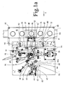
- Fig. 1a and 1b show a schematic representation of a locking device for doors, gates or the like, the locking bolt can be opened by a lock and / or panic unlocking.
- Fig. 1a shows a corresponding door with a locking bolt 10 which is displaceable from the door leaf in the direction of a frame in a recess located in the frame to lock the door relative to the frame.
- a first slider 30 is arranged substantially horizontally.
- the first slider 30 has a horizontal groove 32, which merges into a vertical groove 34.
- a second slider 50 is shown substantially orthogonal to the first slider 30.
- the second slider 50 has a control pin 52, which is arranged in this position in the region of the horizontal groove 32 of the first slider 30.
- a control means designated 56 is provided, which preferably has at least one roller 54, which in the Fig. 1a is indicated.
- a substantially horizontally oriented spring means 40 is disposed between the door and the first slider 30.
- the spring device 40 is preferably formed by a compression spring 45.
- On the first slider 30, a locking member 60 is further arranged, which is shown as a bar or rectangle.
- a pivotable locking device 62 is arranged so that it can engage behind the locking member 60 and can engage with the locking member 60.
- the first slider 30 is horizontally displaceable as soon as the door unlocking by means of a lever which is located outside the door and not shown, in the illustrated view opposite is rotated clockwise to adjust a square 70 counterclockwise.
- a driving pin 72 which is located on a rotating with the square 70 disc 71 and within a substantially vertically disposed in the slide 30 elongated hole 74 is moved; whereby the first slider 30 is moved.
- the driving pin 72 is located in the illustrated embodiment on the indicated with 71 disc, which is in mechanical communication with the square 70, in Fig. 1a is behind the slider 30 and thus rotated together with the driving pin 72. This means that the driving pin 72 moves within the elongated hole 74 together with the disk, not shown, of the bolt work, which sits on the square 70.
- another mechanical coupling mechanism may be provided.
- the first slide 30 is moved by the opening movement to a stop on his in Fig. 1a moved to the left end position.
- lever is a displacement of the slider 30 in Fig. 1a and Fig. 1b as a result
- the T-shaped groove 32, 34 formed in the slider 30 is in Fig. 1a . 1b moved to the left over the pin 52 until the vertical groove 34 is in the range of movement of the pin 52 and the pin 52 together with the second slider 50 in Fig. 1a . 1b down, ie can move perpendicular to the direction of movement of the slider 30.
- the function of the slider 50 and its displacement in the vertical direction depending on the position between the T-shaped groove 32, 34 and control pin 52 will be explained in more detail below.
- Fig. 2 shows a schematic representation of the in Fig. 1a and 1b with 30 designated slider.
- the slider 30 has a slot 35 which serves to receive the pin 72 which is mounted stationary on the lock plate 71 and by rotation of the lock plate, a displacement of the slider 30 in the direction of arrow 2 in Fig. 1a entails.
- the lock plate as described above, on the pin designated 72, which causes the displacement of the slider 30 due to its circular movement.
- the interconnected grooves 32, 34 are further provided and bores 37, 38 which serve to receive an angle 39 which is fixed to the locking bolt 10th connected is. During the opening process, therefore, the locking bar 10 is retracted in the direction of the door leaf to allow the opening of the door relative to the surrounding, not shown door frame.
- the slider 50 is located near the free door edge of a door, on which also at least one locking bar unit 10 is provided, which engages with the door closed in a in the frame, not shown, befmdliche openings.
- the locking bar units are thus at the door on the opposite side to the door hinge and are in coupling relationship with the second slider 50 such that when the slide 50 is raised, ie when the control pin 52 its in Fig. 1a . 1b fully drawn vertical position occupies the locking bar unit occupies the locking position, ie in Fig. 1a fully extended to the right.
- the first slide 30 In descended slide 50 by the downward movement of the slider 50 from its blocking position to the open position, however, the first slide 30 is in Fig. 1a shifted to the left together with the locking bar unit 10, which is then unlocked.
- the movement of the second slider 50 in the vertical direction downwards is preferably supported by a spring means 36 which may be formed as a tension or compression spring.
- the spring device 36 is located between the slider 50 on the one hand and a stationary part of the door on the other.
- the slider 30 is according to Fig. 1a with the spring means 40 in connection, which is formed in the illustrated embodiment as a compression spring and at one end of the slider 30 at 37 rests and is fixed on the door side with the other end.
- the spring device 40 has the purpose of supporting the movement of the slide 30 counter to the arrow direction of the arrow 2.
- a further bolt lock is provided in the door area, which consists of a locking device 62 which is mechanically coupled via an arm 64 with a bolt 65.
- the bolt 65 stands as if Fig. 1a it can be seen from the narrow side of the door side protrudes and is in the closed door in contact with the surrounding door frame. By opening the door, the distance between the belt-side door edge and the door frame is increased. Now, if the door is opened further, the bolt 65 can extend and the arm 64 (clockwise in the illustrated embodiment), whereby the locking device 62 performs a rotation in the clockwise direction and a locking member 60 engages behind, which is provided on the door side.
- the locking device 62 is preferably resiliently biased by a spring device 42 to perform the above-described rotational movement in a clockwise direction as soon as the door has been displaced after actuation of the opening mechanism and after displacement of the first slider 30 in the direction of arrow 2 in a sliding position in which the locking device 62 then the locking member 60 can overlap.
- the locking device 62 is in the illustrated embodiment preferably of a V-shaped lever, one arm 64 is in coupling contact with the bolt 65, while the other arm 66 is provided for engagement with the locking member 60.
- the lever-shaped locking device 62 is pivotally mounted on an axle 66 and by the spring means 42 biased clockwise.
- the arm 66 in the illustrated embodiment is equipped with a hook-shaped end 66a.
- the bolt 65 is in the direction or opposite to the direction of the arrow 2, ie in Fig. 1a in a horizontal direction, displaceable in the door.
- closing the door is as follows: When closing the door of the bolt 65 is pressed against the arrow 2 in the door leaf, causing the locking device 62 moves counterclockwise and the locking member 60 releases. Evidently, the bolt 65 protrudes in the open position of the door only a short distance out of the door leaf, so that the bolt 65 is activated when closing the door only when the door has already been largely shifted towards the closed position, so that one already slight displacement of the bolt 65 is sufficient to rotate the lever-shaped locking device 62 in the counterclockwise direction to displace the hook-shaped end 66a out of engagement with the locking member 60.
- the bias by the spring means 40 causes pressure on the slider 30 against the direction of the arrow 2, but the slider 30 can not yet be displaced as long as the vertical groove portion 34 Control pin 52 receives in the position shown at 52 '.
- the slider 50 must be displaced upwards until the control pin 52 occupies the position shown at 52 'within the groove 34, i. approximately centrally located in the groove 34 so that the slider 30 can be displaced against the direction of arrow 2.
- the control device 56 For adjusting the second slider 50 with the aid of the roller 54, the control device 56 includes an inclined surface on the door underside, preferably provided in the region of the door frame, which in Fig. 1a not shown. By rolling the roller 54 on the inclined surface upwards, the second slider 50 is displaced vertically upwards.
- the second slider 50 is moved as a result of an inclined surface on the underside of the frame by preferably a roller 54 upwards.
- the control pin 52 is displaced from its lower position in the vertical groove 34 in the position 52 'upwards, after which then the first slide 30 against the arrow 2 to is displaced outside and the control pin 52 reaches its initial position within the groove 32.
- At the opposite side of the door hinges is at least one locking bar unit, as indicated above with 10, which passes through the movement of the slider 30 into or out of engagement with corresponding recesses in the door frame.
- the locking bar unit 10 is provided with rollers 80, 82 whose axis of rotation is vertical, i.
- a control mechanism preferably consisting of rollers 80, 82 provided on the door edge side, which run over a lateral inclined surface in the door frame such that the rollers 80, 82 are displaced in the direction of the arrow 2.
- the first slider 30 is displaced together with its vertical groove 34 in the direction of arrow 2 and thus the vertical groove 34 is displaced to the left in a position in the drawing, in which the control pin 52 is vertically adjustable.
- the first slider 30 is not only displaced so far that the control pin 52 stops within the horizontal groove 32, which ends shortly before in the vertical groove 34 (in this case, the first slide 30 could again in a direction opposite to the arrow 2, that is to be shifted back into the closed position).
- the inclined surface which is provided on the frame side, increases in its inclination, with simultaneous opening of the door, whereby the rollers 80, 82 are displaced in the direction of the arrow 2 and consequently also displace the first slide 30 in the direction of the arrow.
- Fig. 1a shows that the locking bar unit 10 is secured by means of bolts 84, 85 and an angle 39 to the slider 30.
- the slider 30 or the angle 39 contains elongated holes for guiding relative to guide pins 88, 89, along which the slider 30 is displaceable in and opposite to the arrow 2.
- pivotable latch 90, 91 are used, which are preferably arranged in the region of the locking bolt 10 and by the operation of the castle from the in Fig. 1a shown rotated position by about 45 ° clockwise.
- the rotary latch 90, 91 are provided door-tight, ie when you open the door, the bolt 90, 91 from the in Fig. 1a shown position adjusted so that they are locking pins 92, 93 opposite and these locking pins 92, 93 able to accommodate, whereby the opening of the door is additionally secured.
- rotatable locking bars 90, 91 are therefore on the one hand on the lock and on the other hand via a panic unlocking not shown in that position in which the locking bar 10 can be moved in the direction of arrow 2 together with the slider 30 for the purpose of door opening.
- the mechanical connection between the lock or panic lever on the one hand and rotatable locking bolts 90, 91 on the other hand is not shown in the drawing.
- the rotatable latches 90, 91 are fixedly provided in the door, ie not displaced together with the slider 30.
- the rotatable bars 90, 91 form an additional security against attacks with explosives, in particular from the outside of the door ago, and prevent in the locked state, a displacement of the locking unit 10 in the direction of the arrow 2.
- the locking device provides a safeguard against the extension of two independent components, namely the horizontal slide 30 and the vertically displaceable slide 50.
- the displacement of the slider 30 takes place when opening the door by means of a driving pin or crank pin 72 in the direction of arrow. 2 against the force of a compression spring 40.
- the control lock includes a Wiederausfahrsperre not completely unlocked bolt work, ie The release of the lock can only be done by the interaction of two components.
- the bolt 65 moves into the door leaf and displaces the locking device 62 in order to release the locking member 60, wherein the slider 30 can only be adjusted when the vertical slide 50 has been moved up and the control pin 52 in the horizontal Groove 32 has occurred. Accordingly, the slider 30 can only be brought into the locking position due to the pressure of the spring means 40 when both the slider 50 and the pin 65 with the locking device 20 have reached the appropriate position for release.
- the slider 50 is in the illustrated embodiment with vertical slots 94, 95, which door-fixed guide pins 96, 97 are assigned, such that the slider 50 is guided along the guide pins 96, 97 in the vertical direction.
- FIG. 2 shows in detail a preferred embodiment of the slider 30 with the horizontal groove 32 and the adjoining vertical groove 34, which is opposite to the groove 32 on the wall side. Furthermore, a slot 35 is provided, in which the driving pin 72 ( Fig. 1 a) engages and by its arcuate movement when opening the door due to a door lever, not shown, relative to the slot 34 of the driver 30 is displaced in the vertical direction to guide in this way the slider 30 in its horizontal movement.
Description
Die vorliegende Erfindung bezieht sich auf eine Riegeleinrichtung für Türen mit mindestens einer an der Tür angeordneten Sperrriegeleinheit, die gegenüber einer in einem Türrahmen ausgebildeten Aussparung oder dergleichen verriegelbar ist.The present invention relates to a locking device for doors with at least one arranged on the door locking latch unit, which is lockable with respect to a recess formed in a door frame or the like.
Die
Eine Riegeleinrichtung für Türen nach dem Oberbegriff des Anspruchs 1 ist aus der
Der Erfindung liegt dem gegenüber die Aufgabe zugrunde, eine Riegeleinrichtung für Türen der eingangs genannten Art zur Verfügung zu stellen, die nach einem Öffnen der Tür ein Wiederausfahren der Riegel sicher verhindert.The invention is based on the object to provide a locking device for doors of the type mentioned above, which reliably prevents reopening of the latch after opening the door.
Diese Aufgabe wird erfindungsgemäß mit einer Riegeleinrichtung für Türen nach Anspruch 1gelöst .This object is achieved with a locking device for doors according to claim 1.
Weitere Ausgestaltungen der Riegeleinrichtung für Türen sind in den Unteransprüchen wiedergegeben.Further embodiments of the locking device for doors are given in the dependent claims.
Die Erfindung schafft eine Riegeleinrichtung für Türen, Tore usw., bei der nach Öffnung der Tür die Sperrriegeleinheit zusammen mit einem Schieber in Richtung Offenstellung verarbeitet wird und dabei der mit der Sperrriegeleinheit gekuppelte Schieber nach Durchführung einer Verlagerung durch eine Sperreinrichtung arretiert wird, wodurch ein Wiederausfahren der Sperrriegeleinheit verhindert wird. Die Weiterbewegung des Schiebers in Richtung Offenstellung bewirkt die Aktivierung eines zweiten, vertikal sich bewegenden Schiebers mit einem Steuerzapfen, der in eine vertikale Nut des ersten Schiebers eingreift und dadurch das Wiederausfahren des ersten Schiebers zusammen mit der Sperrriegeleinheit verhindert. Damit wird das Wiederausfahren der Sperrriegeleinheit durch zwei Maßnahmen verhindert, die entweder gleichzeitig oder aufeinanderfolgend aktiviert werden. Beim Schließen der Tür wird zunächst die Sperreinheit deaktiviert, indem sie ein am ersten Schieber vorgesehenes Sperrglied freigibt, bevor durch Betätigung des zweiten Schiebers in Vertikalrichtung nach oben der Steuerzapfen des zweiten Schiebers in eine Horizontalnut des ersten Schiebers gelangt, wodurch der erste Schieber zum Ausfahren der Sperrriegeleinheit freigegeben wird. Beim Öffnen der Tür sind bei einer bevorzugten Ausführungsform weitere unterstützende Maßnahmen vorgesehen in Form von Rollen mit einer Drehachse, die in der Türebene liegt. Durch diese Rollen wird beim Öffnen der Tür der Sperrriegel durch Abfahren einer schiefen Ebene zurückgefahren, und zwar so weit, bis die anderen Sperreinheiten in Funktion treten.The invention provides a locking device for doors, gates, etc., in which after opening the door, the locking bar unit is processed together with a slide towards the open position while the coupled with the locking bar unit slide is locked after carrying out a displacement by a locking device, whereby a Wiederausfahren the locking bar unit is prevented. The further movement of the slider in the open position causes the activation of a second, vertically moving slider with a control pin which engages in a vertical groove of the first slider and thereby prevents the re-extension of the first slider together with the locking bar unit. Thus, the re-extension of the locking bar unit is prevented by two measures that are activated either simultaneously or sequentially. When closing the door, the locking unit is first deactivated by releasing a locking member provided on the first slider before, by operating the second slider in the vertical upward direction of the control pin of the second slider enters a horizontal groove of the first slider, whereby the first slider for extending the Locking bar unit is released. When opening the door further supportive measures are provided in the form of roles with a rotation axis, which lies in the door level in a preferred embodiment. Through these roles when unlocking the door of the locking bolt is moved back by driving down an inclined plane, and indeed so far until the other locking units come into operation.
Die Erfindung wird im Folgenden anhand eines Ausführungsbeispiels unter Bezugnahme auf die beiliegenden Figuren der Zeichnungen näher erläutert. Von den Figuren zeigen:
- Figur 1a
- Eine schematische Schnittdarstellung einer erfindungsgemäßen Riegeleinrichtung für Türen gemäß einem bevorzugten Ausführungsbeispiel der vorliegenden Erfin- dung,
- Figur 1b
- eine vergrößerte Teilansicht zu
Figur 1a , und Figur 2- eine schematische Darstellung eines ersten Schiebers der erfindungsgemäßen Rie- geleinrichtung.
- FIG. 1a
- A schematic sectional view of a latching device according to the invention for doors according to a preferred embodiment of the present invention,
- FIG. 1b
- an enlarged partial view too
FIG. 1a , and - FIG. 2
- a schematic representation of a first slider of the invention Rieg geleinrichtung.
Ein erster Schieber 30 ist im Wesentlichen horizontal angeordnet. Der erste Schieber 30 weist eine horizontale Nut 32 auf, die in eine vertikale Nut 34 übergeht. Ein zweiter Schieber 50 ist im Wesentlichen orthogonal zum ersten Schieber 30 dargestellt. Der zweite Schieber 50 weist einen Steuerzapfen 52 auf, der in dieser Stellung im Bereich der horizontalen Nut 32 des ersten Schiebers 30 angeordnet ist. An dem unteren Ende des zweiten Schiebers 50 ist eine mit 56 bezeichnete Steuereinrichtung vorgesehen, die vorzugsweise wenigstens eine Rolle 54 aufweist, die in der
Der erste Schieber 30 ist horizontal verlagerbar, sobald die Türentriegelung mittels eines Hebels, der sich außerhalb der Tür befindet und nicht dargestellt ist, bei der dargestellten Ansicht entgegen dem Uhrzeigersinn verdreht wird, um einen Vierkant 70 im Gegenuhrzeigersinn zu verstellen. Durch die Drehung des Vierkants 70 wird ein Mitnehmerzapfen 72, der sich auf einer mit dem Vierkant 70 drehenden Scheibe 71 und innerhalb eines im Wesentlichen vertikal im Schieber 30 angeordneten Langloches 74 befindet, bewegt; wodurch der erste Schieber 30 verschoben wird. Der Mitnehmerzapfen 72 befindet sich bei der dargestellten Ausführungsform auf der mit 71 angedeuteten Scheibe, die mit dem Vierkant 70 in mechanischer Verbindung steht, in
Der erste Schieber 30 wird durch die Öffnungsbewegung bis zu einem Anschlag an seiner in
In dem Schieber 30 sind weiterhin die miteinander verbundenen Nuten 32, 34 vorgesehen sowie Bohrungen 37, 38, die zur Aufnahme eines Winkels 39 dienen, der fest mit dem Sperrriegel 10 verbunden ist. Beim Öffnungsvorgang wird also der Sperrriegel 10 in Richtung des Türblattes zurückgezogen, um das Öffnen der Tür gegenüber der umgebenden, nicht dargestellten Türzarge zu ermöglichen.In the
Es sei bemerkt, dass sich der Schieber 50 nahe der freien Türkante einer Tür befindet, an welcher auch mindestens eine Sperrriegeleinheit 10 vorgesehen ist, die bei geschlossener Tür in eine in der nicht dargestellten Zarge befmdliche Öffnungen eingreift. Die Sperrriegeleinheiten befinden sich also bei der Tür auf der zum Türband entgegengesetzten Seite und stehen in Kupplungsbeziehung mit dem zweiten Schieber 50 derart, dass bei hochgefahrenem Schieber 50, d. h. wenn der Steuerzapfen 52 seine in
Durch die Öffnung des Schlosses über die Drehung des Vierkants 70 wird also der Schieber 30 in
Zugleich ist sichergestellt, dass - sobald der Steuerzapfen 52 am Boden der Nut 34 aufliegt - der Schieber 30 nicht mehr entgegen der Richtung des Pfeils 2 verschoben werden kann, da die Verlagerung des Schiebers 30 durch den Eingriff zwischen der vertikalen Nut 34 und dem Steuerzapfen 52 verhindert wird.At the same time it is ensured that - as soon as the
Die Bewegung des zweiten Schiebers 50 in Vertikalrichtung nach unten wird vorzugsweise durch eine Federeinrichtung 36 unterstützt, die als Zug- oder Druckfeder ausgebildet sein kann. Die Federeinrichtung 36 befindet sich zwischen dem Schieber 50 einerseits und einem stationären Teil der Tür andererseits.The movement of the
Der Schieber 30 steht gemäß
Gemäß einer bevorzugten Ausführungsform ist im Türbereich eine weitere Riegelsperre vorgesehen, die aus einer Sperreinrichtung 62 besteht, die über einen Arm 64 mit einem Bolzen 65 mechanisch gekoppelt ist. Der Bolzen 65 steht, wie aus
Die Sperreinrichtung 62 besteht bei der dargestellten Ausführungsform vorzugsweise aus einem V-förmigen Hebel, dessen einer Arm 64 in Kupplungskontakt mit dem Bolzen 65 steht, während der andere Arm 66 zum Eingriff gegenüber dem Sperrglied 60 vorgesehen ist. Die hebelförmige Sperreinrichtung 62 ist schwenkfähig auf einer Achse 66 gelagert und durch die Federeinrichtung 42 im Uhrzeigersinn vorgespannt. Damit der Arm 66 bei der dargestellten Ausführungsform das Sperrglied 60 in Form einer Leiste oder eines Rechteckblocks übergreifen kann, ist der Arm 66 mit einem hakenförmigen Ende 66a ausgerüstet. Der Bolzen 65 ist in Richtung bzw. entgegengesetzt zur Richtung des Pfeils 2, d.h. in
In umgekehrter Weise erfolgt das Schließen der Türe wie folgt: Beim Schließen der Türe wird der Bolzen 65 entgegen dem Pfeil 2 in das Türblatt hineingedrückt, wodurch sich die Sperreinrichtung 62 entgegen dem Uhrzeigersinn bewegt und das Sperrglied 60 freigibt. Ersichtlicherweise ragt der Bolzen 65 in der Offenstellung der Tür nur über eine kurze Distanz aus dem Türblatt heraus, so dass der Bolzen 65 beim Schließen der Tür erst dann aktiviert wird, wenn die Tür bereits weitgehend Richtung geschlossene Stellung verlagert worden ist, so dass eine bereits geringfügige Verlagerung des Bolzens 65 ausreicht, um die hebelförmige Sperreinrichtung 62 entgegen dem Uhrzeigersinn zu verdrehen, um das hakenförmige Ende 66a außer Eingriff mit dem Sperrglied 60 zu verlagern. Sobald der Hakenabschnitt 66a außer Eingriff zum Sperrglied 60 verbracht worden ist, bewirkt die Vorspannung durch die Federeinrichtung 40 einen Druck auf den Schieber 30 entgegen der Richtung des Pfeiles 2, wobei der Schieber 30 jedoch noch nicht verlagert werden kann, solange der vertikale Nutabschnitt 34 den Steuerzapfen 52 in der mit 52' gezeigten Position aufnimmt. Zunächst muss nämlich der Schieber 50 aufgrund der Wirkung der Rolle 54 nach oben verlagert werden, so weit, bis der Steuerzapfen 52 die mit 52' dargestellte Positionierung innerhalb der Nut 34 einnimmt, d.h. etwa mittig in der Nut 34 liegt, damit der Schieber 30 entgegen der Richtung des Pfeils 2 verlagert werden kann.Conversely, closing the door is as follows: When closing the door of the
Zur Verstellung des zweiten Schiebers 50 unter Zuhilfenahme der Rolle 54 beinhaltet die Steuereinrichtung 56 an der Türunterseite eine Schrägfläche, vorzugsweise im Bereich der Türzarge vorgesehen, die in
Wenn die Türe weiter geschlossen wird, wird also der zweite Schieber 50 infolge einer Schrägfläche an der Unterseite der Zarge durch vorzugsweise eine Rolle 54 nach oben bewegt. Dabei wird gleichzeitig der Steuerzapfen 52 aus seiner unteren Position in der vertikalen Nut 34 in die Position 52' nach oben verlagert, wonach dann der erste Schieber 30 entgegen dem Pfeil 2 nach außen verlagert wird und der Steuerzapfen 52 in seine Ausgangsstellung innerhalb der Nut 32 gelangt.If the door is closed further, so the
An der den Türbändern gegenüberliegenden Seite befindet sich mindestens eine Sperrriegeleinheit, wie sie vorstehend mit 10 angegeben ist, die durch die Bewegung des Schiebers 30 in bzw. außer Eingriff mit entsprechenden Aussparungen in der Türzarge gelangt. Gemäß einer bevorzugten Ausführungsform ist die Sperrriegeleinheit 10 mit Rollen 80, 82 versehen, deren Drehachse vertikal verläuft, d.h. in der Türebene, und die mit einer Schrägfläche im Bereich der Türzarge in Eingriff gebracht werden können, wobei die Schrägfläche in der Türzarge oder im Bereich der Sperniegelöffnung eine schiefe Ebene bildet, derart, dass beim Aufziehen der Tür die Rollen 80, 82 über die schiefe Ebene laufen und dadurch den Sperrriegel 10 in Richtung des Pfeils 2 drücken, damit die Sperreinrichtung 62 aktiv wird und das Sperrglied 60 übergreift, so dass der Riegel 10 an einem wiederholten Ausfahren gehindert wird. Mit anderen Worten heißt dies, dass bereits während des Aufziehens der Tür aufgrund der Rollen 80, 82 der Riegel 10 in Richtung des Pfeiles 2 so weit verlagert wird, dass er außer Eingriff mit der jeweiligen Aussparung gelangt, die in der Türzarge vorgesehen ist, und dass anschließend der Schieber 30 weiter gegen die Wirkung der Feder 40 verlagerbar ist, um den vertikalen Schieber 50 mit dem Steuerzapfen 52 für eine Vertikalbewegung nach unten freizugeben. Damit ist auch gewährleistet, dass erst ab dem Zeitpunkt, ab welchem sich der Steuerzapfen 54 im Verhältnis zur vertikalen Nut 34 innerhalb der vertikalen Nut 34 befindet, der zweite Schieber 50 nach unten bewegt werden kann.At the opposite side of the door hinges is at least one locking bar unit, as indicated above with 10, which passes through the movement of the
Gemäß einer weiteren Ausführungsform ist an der Türkantenseite ein Steuermechanismus, vorzugsweise aus Rollen 80, 82 bestehend, vorgesehen, die über eine seitliche Schrägfläche in der Türzarge derart laufen, dass die Rollen 80, 82 in Richtung des Pfeils 2 verlagert werden. Dies hat zur Folge, dass der erste Schieber 30 zusammen mit seiner vertikalen Nut 34 in Richtung des Pfeils 2 verlagert wird und damit die vertikale Nut 34 in eine Position in der Zeichnung nach links verlagert wird, in welcher der Steuerzapfen 52 vertikal verstellbar ist. Um zu gewährleisten, dass beim Öffnen der Tür der erste Schieber 30 nicht nur soweit verlagert wird, dass der Steuerzapfen 52 innerhalb der horizontalen Nut 32 stehen bleibt, die kurz davor in der vertikalen Nut 34 endet (in diesem Fall könnte der erste Schieber 30 wieder in eine Richtung entgegen dem Pfeil 2, das heißt in die Schließposition zurückverlagert werden).According to a further embodiment, a control mechanism, preferably consisting of
Diese Funktion wird dadurch besser verständlich, dass sich die Nuten 34 und 32, die im ersten Schieber 30 ausgebildet sind, zusammen mit dem ersten Schieber 30 in Richtung des Pfeiles 2 bzw. entgegengesetzt dazu verlagern, während der Steuerzapfen 52 türseitig fest angeordnet ist, aber eine Bewegung in vertikaler Richtung ausführen kann, sobald die vertikale Nut 34 die Position des Steuerzapfens 52 erreicht hat.This function can be better understood that the
Die Schrägfläche, die rahmenseitig vorgesehen ist, nimmt in ihrer Steigung, bei gleichzeitiger Öffnung der Türe zu, wodurch die Rollen 80, 82 in Richtung des Pfeils 2 verlagert werden und demzufolge auch den ersten Schieber 30 in Richtung des Pfeils verlagern.The inclined surface, which is provided on the frame side, increases in its inclination, with simultaneous opening of the door, whereby the
Aus
Weiterhin ist bei der dargestellten Ausführungsform vorgesehen, verschwenkbare Riegel 90, 91 einzusetzen, die vorzugsweise im Bereich des Sperrriegels 10 angeordnet sind und die durch die Betätigung des Schlosses aus der in
Die erfindungsgemäße Riegeleinrichtung stellt eine Sicherung gegen das Ausfahren von zwei unabhängigen Bauteilen dar, nämlich den horizontalen Schieber 30 sowie den vertikal verlagerbaren Schieber 50. Die Verlagerung des Schiebers 30 erfolgt beim Öffnen der Tür mit Hilfe eines Mitnehmerzapfens bzw. Kurbelzapfens 72 in Richtung des Pfeils 2 gegen die Kraft einer Druckfeder 40. Zugleich beinhaltet die Regelsperre eine Wiederausfahrsperre bei nicht vollkommen entriegeltem Riegelwerk, d.h. die Freigabe der Verriegelung kann nur durch das Zusammenwirken von zwei Komponenten erfolgen. Beim Zuschwenken der Tür bewegt sich der Bolzen 65 in das Türblatt hinein und verstellt die Sperreinrichtung 62 zwecks Freigabe des Sperrglieds 60, wobei der Schieber 30 sich erst dann verstellen kann, wenn der vertikale Schieber 50 nach oben bewegt wurde und der Steuerzapfen 52 in die horizontale Nut 32 eingetreten ist. Demzufolge kann der Schieber 30 erst dann in die Verriegelungsposition aufgrund des Druckes der Federeinrichtung 40 verbracht werden, wenn sowohl der Schieber 50 als auch der Bolzen 65 mit der Sperreinrichtung 20 die entsprechende Position zur Freigabe erreicht haben.The locking device according to the invention provides a safeguard against the extension of two independent components, namely the
Wie aus
Claims (3)
- Door locking device having at least one locking bolt unit (10) which is disposed on the door and is lockable with respect to a recess or the like formed in a door frame (20),- having a first slide (30) which can be displaced substantially horizontally against a resilient device (40) into a first position,- wherein the first slide (30) comprises a substantially horizontal groove (52) which is connected to a substantially vertical groove (34) of the first slide (30), having a second slide (50), which- is provided with a control spigot (52) with respect to which the first slide (30) can be displaced along the grooves (32, 34),- wherein the second slide (50) can be displaced approximately perpendicular to the first slide (30),- wherein in a second position of the first slide (30) the second slide (50) can be displaced into a second position by virtue of the engagement between the control spigot (52) and the vertical groove (34), in which second position the first slide (30) is locked, characterized in that
the second position of the second slide (50) represents a downwards displaced position,
that a locking device (62) disposed on the door-side is provided and that the first slide (30) comprises a locking member (60) which can be brought into engagement with the locking device (62), wherein the locking device (62) is coupled to a bolt (65) which is provided in such a manner that it can be displaced with respect to the door,
that the locking member (60) and the locking device (62) can be brought into engagement as soon as the first slide (30) is displaced into a position corresponding to the open position. - Locking device as claimed in claim 1, characterized in that the locking device (62) comprises a lever (64, 66) which can be displaced about an axis, wherein one end (66) of the lever (64, 66) is connected to the bolt (65).
- Locking device as claimed in claim 1 or 2, characterized in that a control device (56) is provided for the second slide (50) which consists of an inclined surface formed on the door frame (20), with respect to which at least one roller (54) is guided, which roller is disposed on the second slide (50) in order during a closing movement of the door to displace the second slide (50) into a position in which the second slide (50) releases the first slide (30).
Applications Claiming Priority (1)
| Application Number | Priority Date | Filing Date | Title |
|---|---|---|---|
| DE102008040655A DE102008040655A1 (en) | 2008-07-23 | 2008-07-23 | Locking device for doors |
Publications (2)
| Publication Number | Publication Date |
|---|---|
| EP2148028A1 EP2148028A1 (en) | 2010-01-27 |
| EP2148028B1 true EP2148028B1 (en) | 2011-02-16 |
Family
ID=40282203
Family Applications (1)
| Application Number | Title | Priority Date | Filing Date |
|---|---|---|---|
| EP20080170338 Active EP2148028B1 (en) | 2008-07-23 | 2008-12-01 | Door locking device |
Country Status (2)
| Country | Link |
|---|---|
| EP (1) | EP2148028B1 (en) |
| DE (2) | DE102008040655A1 (en) |
Families Citing this family (1)
| Publication number | Priority date | Publication date | Assignee | Title |
|---|---|---|---|---|
| CN102787761B (en) * | 2012-07-18 | 2015-04-01 | 夏志云 | Lock body with automatic lock mechanism attached with buffer device |
Family Cites Families (6)
| Publication number | Priority date | Publication date | Assignee | Title |
|---|---|---|---|---|
| US2959440A (en) * | 1958-07-30 | 1960-11-08 | Daniel C Hay | Emergency exit door and lock mechanism therefor |
| DE19628012C2 (en) | 1996-07-11 | 2003-01-23 | Sommer Metallbau Stahlbau Gmbh | Extension lock for the bolts of a bolt work |
| DE19628011C5 (en) | 1996-07-11 | 2008-11-20 | Sommer Metallbau-Stahlbau Gmbh & Co. Kg | Spreader for the bolt a bolt factory |
| DE19628010C2 (en) | 1996-07-11 | 2003-04-10 | Sommer Metallbau Stahlbau Gmbh | Device for adjusting the push rod of a bolt work |
| DE10206095B4 (en) * | 2002-02-13 | 2006-05-04 | F.S. Fehrer Automotive Systems Gmbh | Pivotally mounted component in a motor vehicle |
| GB2423787B (en) * | 2005-03-01 | 2009-07-22 | Surelock Mcgill Ltd | Bi-directional bolt restraint mechanism |
-
2008
- 2008-07-23 DE DE102008040655A patent/DE102008040655A1/en not_active Ceased
- 2008-12-01 DE DE200850002617 patent/DE502008002617D1/en active Active
- 2008-12-01 EP EP20080170338 patent/EP2148028B1/en active Active
Also Published As
| Publication number | Publication date |
|---|---|
| DE502008002617D1 (en) | 2011-03-31 |
| EP2148028A1 (en) | 2010-01-27 |
| DE102008040655A1 (en) | 2010-02-04 |
Similar Documents
| Publication | Publication Date | Title |
|---|---|---|
| EP0668425B1 (en) | Door lock | |
| EP0854261B1 (en) | Automatically releasing lock | |
| EP0156379B1 (en) | Cash drawer for a cash register | |
| EP2706174B1 (en) | Lock for a door | |
| EP2843169B1 (en) | Sliding door with support system | |
| EP3109385B1 (en) | Closure device for a door with a single or multi-part door leaf | |
| EP0021080B1 (en) | Lifting, sliding or swinging door or window | |
| EP0789121A1 (en) | Additional lock for wings of doors, windows or similar | |
| EP2148028B1 (en) | Door locking device | |
| DE3334298C3 (en) | Lock for windows, doors or the like | |
| EP0885340B1 (en) | Locking device for a wing, in particular a door with a plurality of locking bolts | |
| EP3752700A1 (en) | Lowerable intruder protection | |
| DE3034764C2 (en) | Actuating device for espagnolette fittings | |
| DE19628011C2 (en) | Locking device for the bolts of a bolt work | |
| EP3122968B1 (en) | Switch lock with tamper-proofing for preventing an auxiliary latch actuation | |
| DE1653995A1 (en) | Safety device | |
| DE2658626B2 (en) | Switching lock for espagnolette fittings | |
| EP0846825B1 (en) | Locking device for a door wing movable in a case | |
| DE19906232B4 (en) | Device for locking and unlocking a passive leaf | |
| DE10162194B4 (en) | Boltwork control | |
| EP0509128B1 (en) | Actuating device for a door | |
| DE19923433C2 (en) | Locking device, in particular for a door | |
| EP1067270B1 (en) | Locking device for a shutter for an opening in a building, particularly for a roller shutter | |
| DE19628010C2 (en) | Device for adjusting the push rod of a bolt work | |
| DE19628012C2 (en) | Extension lock for the bolts of a bolt work |
Legal Events
| Date | Code | Title | Description |
|---|---|---|---|
| PUAI | Public reference made under article 153(3) epc to a published international application that has entered the european phase |
Free format text: ORIGINAL CODE: 0009012 |
|
| 17P | Request for examination filed |
Effective date: 20081201 |
|
| AK | Designated contracting states |
Kind code of ref document: A1 Designated state(s): AT BE BG CH CY CZ DE DK EE ES FI FR GB GR HR HU IE IS IT LI LT LU LV MC MT NL NO PL PT RO SE SI SK TR |
|
| AX | Request for extension of the european patent |
Extension state: AL BA MK RS |
|
| GRAP | Despatch of communication of intention to grant a patent |
Free format text: ORIGINAL CODE: EPIDOSNIGR1 |
|
| AKX | Designation fees paid |
Designated state(s): CH DE FI FR GB LI SE |
|
| GRAS | Grant fee paid |
Free format text: ORIGINAL CODE: EPIDOSNIGR3 |
|
| GRAA | (expected) grant |
Free format text: ORIGINAL CODE: 0009210 |
|
| AK | Designated contracting states |
Kind code of ref document: B1 Designated state(s): CH DE FI FR GB LI SE |
|
| REG | Reference to a national code |
Ref country code: GB Ref legal event code: FG4D Free format text: NOT ENGLISH |
|
| REG | Reference to a national code |
Ref country code: CH Ref legal event code: EP |
|
| REF | Corresponds to: |
Ref document number: 502008002617 Country of ref document: DE Date of ref document: 20110331 Kind code of ref document: P |
|
| REG | Reference to a national code |
Ref country code: DE Ref legal event code: R096 Ref document number: 502008002617 Country of ref document: DE Effective date: 20110331 |
|
| REG | Reference to a national code |
Ref country code: CH Ref legal event code: NV Representative=s name: HEPP WENGER RYFFEL AG |
|
| REG | Reference to a national code |
Ref country code: SE Ref legal event code: TRGR |
|
| PLBE | No opposition filed within time limit |
Free format text: ORIGINAL CODE: 0009261 |
|
| STAA | Information on the status of an ep patent application or granted ep patent |
Free format text: STATUS: NO OPPOSITION FILED WITHIN TIME LIMIT |
|
| 26N | No opposition filed |
Effective date: 20111117 |
|
| REG | Reference to a national code |
Ref country code: DE Ref legal event code: R097 Ref document number: 502008002617 Country of ref document: DE Effective date: 20111117 |
|
| REG | Reference to a national code |
Ref country code: FR Ref legal event code: PLFP Year of fee payment: 8 |
|
| REG | Reference to a national code |
Ref country code: FR Ref legal event code: PLFP Year of fee payment: 9 |
|
| REG | Reference to a national code |
Ref country code: FR Ref legal event code: PLFP Year of fee payment: 10 |
|
| PGFP | Annual fee paid to national office [announced via postgrant information from national office to epo] |
Ref country code: CH Payment date: 20221213 Year of fee payment: 15 |
|
| PGFP | Annual fee paid to national office [announced via postgrant information from national office to epo] |
Ref country code: DE Payment date: 20221230 Year of fee payment: 15 |
|
| P01 | Opt-out of the competence of the unified patent court (upc) registered |
Effective date: 20230419 |
|
| PGFP | Annual fee paid to national office [announced via postgrant information from national office to epo] |
Ref country code: GB Payment date: 20231220 Year of fee payment: 16 |
|
| PGFP | Annual fee paid to national office [announced via postgrant information from national office to epo] |
Ref country code: SE Payment date: 20231220 Year of fee payment: 16 Ref country code: FR Payment date: 20231221 Year of fee payment: 16 Ref country code: FI Payment date: 20231220 Year of fee payment: 16 |