EP3851346B1 - Modèle de pneu inverse pour la gestion avancée de mouvement de véhicule - Google Patents
Modèle de pneu inverse pour la gestion avancée de mouvement de véhicule Download PDFInfo
- Publication number
- EP3851346B1 EP3851346B1 EP20203293.4A EP20203293A EP3851346B1 EP 3851346 B1 EP3851346 B1 EP 3851346B1 EP 20203293 A EP20203293 A EP 20203293A EP 3851346 B1 EP3851346 B1 EP 3851346B1
- Authority
- EP
- European Patent Office
- Prior art keywords
- wheel
- control unit
- tyre
- inverse
- slip
- Prior art date
- Legal status (The legal status is an assumption and is not a legal conclusion. Google has not performed a legal analysis and makes no representation as to the accuracy of the status listed.)
- Active
Links
- 230000006870 function Effects 0.000 claims description 46
- 238000000034 method Methods 0.000 claims description 23
- 230000004044 response Effects 0.000 claims description 14
- 230000006399 behavior Effects 0.000 claims description 11
- 238000012545 processing Methods 0.000 claims description 11
- 238000004590 computer program Methods 0.000 claims description 8
- 238000005096 rolling process Methods 0.000 claims description 6
- 238000013528 artificial neural network Methods 0.000 claims description 4
- 208000035032 Multiple sulfatase deficiency Diseases 0.000 description 16
- 201000006033 mucosulfatidosis Diseases 0.000 description 16
- 230000001133 acceleration Effects 0.000 description 15
- 230000008901 benefit Effects 0.000 description 15
- 230000008859 change Effects 0.000 description 12
- 238000005259 measurement Methods 0.000 description 10
- 238000013507 mapping Methods 0.000 description 8
- 230000006978 adaptation Effects 0.000 description 6
- 238000013459 approach Methods 0.000 description 5
- 230000000694 effects Effects 0.000 description 5
- 238000004891 communication Methods 0.000 description 4
- 230000003044 adaptive effect Effects 0.000 description 3
- 238000000418 atomic force spectrum Methods 0.000 description 3
- 238000012544 monitoring process Methods 0.000 description 3
- 230000008569 process Effects 0.000 description 3
- 230000003542 behavioural effect Effects 0.000 description 2
- 238000002485 combustion reaction Methods 0.000 description 2
- 238000010276 construction Methods 0.000 description 2
- 238000013461 design Methods 0.000 description 2
- JJLJMEJHUUYSSY-UHFFFAOYSA-L Copper hydroxide Chemical compound [OH-].[OH-].[Cu+2] JJLJMEJHUUYSSY-UHFFFAOYSA-L 0.000 description 1
- 239000006096 absorbing agent Substances 0.000 description 1
- 239000010426 asphalt Substances 0.000 description 1
- 238000006243 chemical reaction Methods 0.000 description 1
- 230000007423 decrease Effects 0.000 description 1
- 238000009795 derivation Methods 0.000 description 1
- 238000005516 engineering process Methods 0.000 description 1
- 238000002474 experimental method Methods 0.000 description 1
- HDDSHPAODJUKPD-UHFFFAOYSA-N fenbendazole Chemical compound C1=C2NC(NC(=O)OC)=NC2=CC=C1SC1=CC=CC=C1 HDDSHPAODJUKPD-UHFFFAOYSA-N 0.000 description 1
- 239000010410 layer Substances 0.000 description 1
- 239000002346 layers by function Substances 0.000 description 1
- 238000012986 modification Methods 0.000 description 1
- 230000004048 modification Effects 0.000 description 1
- 230000003287 optical effect Effects 0.000 description 1
- 230000002085 persistent effect Effects 0.000 description 1
- 230000001172 regenerating effect Effects 0.000 description 1
- 230000035939 shock Effects 0.000 description 1
- 239000007787 solid Substances 0.000 description 1
- 239000000725 suspension Substances 0.000 description 1
- 238000010200 validation analysis Methods 0.000 description 1
- 238000012795 verification Methods 0.000 description 1
Images

Classifications
-
- B—PERFORMING OPERATIONS; TRANSPORTING
- B60—VEHICLES IN GENERAL
- B60W—CONJOINT CONTROL OF VEHICLE SUB-UNITS OF DIFFERENT TYPE OR DIFFERENT FUNCTION; CONTROL SYSTEMS SPECIALLY ADAPTED FOR HYBRID VEHICLES; ROAD VEHICLE DRIVE CONTROL SYSTEMS FOR PURPOSES NOT RELATED TO THE CONTROL OF A PARTICULAR SUB-UNIT
- B60W10/00—Conjoint control of vehicle sub-units of different type or different function
- B60W10/18—Conjoint control of vehicle sub-units of different type or different function including control of braking systems
- B60W10/184—Conjoint control of vehicle sub-units of different type or different function including control of braking systems with wheel brakes
-
- B—PERFORMING OPERATIONS; TRANSPORTING
- B60—VEHICLES IN GENERAL
- B60T—VEHICLE BRAKE CONTROL SYSTEMS OR PARTS THEREOF; BRAKE CONTROL SYSTEMS OR PARTS THEREOF, IN GENERAL; ARRANGEMENT OF BRAKING ELEMENTS ON VEHICLES IN GENERAL; PORTABLE DEVICES FOR PREVENTING UNWANTED MOVEMENT OF VEHICLES; VEHICLE MODIFICATIONS TO FACILITATE COOLING OF BRAKES
- B60T8/00—Arrangements for adjusting wheel-braking force to meet varying vehicular or ground-surface conditions, e.g. limiting or varying distribution of braking force
- B60T8/17—Using electrical or electronic regulation means to control braking
- B60T8/172—Determining control parameters used in the regulation, e.g. by calculations involving measured or detected parameters
-
- B—PERFORMING OPERATIONS; TRANSPORTING
- B60—VEHICLES IN GENERAL
- B60W—CONJOINT CONTROL OF VEHICLE SUB-UNITS OF DIFFERENT TYPE OR DIFFERENT FUNCTION; CONTROL SYSTEMS SPECIALLY ADAPTED FOR HYBRID VEHICLES; ROAD VEHICLE DRIVE CONTROL SYSTEMS FOR PURPOSES NOT RELATED TO THE CONTROL OF A PARTICULAR SUB-UNIT
- B60W30/00—Purposes of road vehicle drive control systems not related to the control of a particular sub-unit, e.g. of systems using conjoint control of vehicle sub-units
- B60W30/18—Propelling the vehicle
- B60W30/18172—Preventing, or responsive to skidding of wheels
-
- B—PERFORMING OPERATIONS; TRANSPORTING
- B60—VEHICLES IN GENERAL
- B60T—VEHICLE BRAKE CONTROL SYSTEMS OR PARTS THEREOF; BRAKE CONTROL SYSTEMS OR PARTS THEREOF, IN GENERAL; ARRANGEMENT OF BRAKING ELEMENTS ON VEHICLES IN GENERAL; PORTABLE DEVICES FOR PREVENTING UNWANTED MOVEMENT OF VEHICLES; VEHICLE MODIFICATIONS TO FACILITATE COOLING OF BRAKES
- B60T8/00—Arrangements for adjusting wheel-braking force to meet varying vehicular or ground-surface conditions, e.g. limiting or varying distribution of braking force
- B60T8/17—Using electrical or electronic regulation means to control braking
- B60T8/176—Brake regulation specially adapted to prevent excessive wheel slip during vehicle deceleration, e.g. ABS
- B60T8/1761—Brake regulation specially adapted to prevent excessive wheel slip during vehicle deceleration, e.g. ABS responsive to wheel or brake dynamics, e.g. wheel slip, wheel acceleration or rate of change of brake fluid pressure
- B60T8/17616—Microprocessor-based systems
-
- B—PERFORMING OPERATIONS; TRANSPORTING
- B60—VEHICLES IN GENERAL
- B60T—VEHICLE BRAKE CONTROL SYSTEMS OR PARTS THEREOF; BRAKE CONTROL SYSTEMS OR PARTS THEREOF, IN GENERAL; ARRANGEMENT OF BRAKING ELEMENTS ON VEHICLES IN GENERAL; PORTABLE DEVICES FOR PREVENTING UNWANTED MOVEMENT OF VEHICLES; VEHICLE MODIFICATIONS TO FACILITATE COOLING OF BRAKES
- B60T8/00—Arrangements for adjusting wheel-braking force to meet varying vehicular or ground-surface conditions, e.g. limiting or varying distribution of braking force
- B60T8/17—Using electrical or electronic regulation means to control braking
- B60T8/1701—Braking or traction control means specially adapted for particular types of vehicles
- B60T8/1708—Braking or traction control means specially adapted for particular types of vehicles for lorries or tractor-trailer combinations
-
- B—PERFORMING OPERATIONS; TRANSPORTING
- B60—VEHICLES IN GENERAL
- B60T—VEHICLE BRAKE CONTROL SYSTEMS OR PARTS THEREOF; BRAKE CONTROL SYSTEMS OR PARTS THEREOF, IN GENERAL; ARRANGEMENT OF BRAKING ELEMENTS ON VEHICLES IN GENERAL; PORTABLE DEVICES FOR PREVENTING UNWANTED MOVEMENT OF VEHICLES; VEHICLE MODIFICATIONS TO FACILITATE COOLING OF BRAKES
- B60T8/00—Arrangements for adjusting wheel-braking force to meet varying vehicular or ground-surface conditions, e.g. limiting or varying distribution of braking force
- B60T8/17—Using electrical or electronic regulation means to control braking
- B60T8/171—Detecting parameters used in the regulation; Measuring values used in the regulation
-
- B—PERFORMING OPERATIONS; TRANSPORTING
- B60—VEHICLES IN GENERAL
- B60T—VEHICLE BRAKE CONTROL SYSTEMS OR PARTS THEREOF; BRAKE CONTROL SYSTEMS OR PARTS THEREOF, IN GENERAL; ARRANGEMENT OF BRAKING ELEMENTS ON VEHICLES IN GENERAL; PORTABLE DEVICES FOR PREVENTING UNWANTED MOVEMENT OF VEHICLES; VEHICLE MODIFICATIONS TO FACILITATE COOLING OF BRAKES
- B60T8/00—Arrangements for adjusting wheel-braking force to meet varying vehicular or ground-surface conditions, e.g. limiting or varying distribution of braking force
- B60T8/17—Using electrical or electronic regulation means to control braking
- B60T8/175—Brake regulation specially adapted to prevent excessive wheel spin during vehicle acceleration, e.g. for traction control
-
- B—PERFORMING OPERATIONS; TRANSPORTING
- B60—VEHICLES IN GENERAL
- B60T—VEHICLE BRAKE CONTROL SYSTEMS OR PARTS THEREOF; BRAKE CONTROL SYSTEMS OR PARTS THEREOF, IN GENERAL; ARRANGEMENT OF BRAKING ELEMENTS ON VEHICLES IN GENERAL; PORTABLE DEVICES FOR PREVENTING UNWANTED MOVEMENT OF VEHICLES; VEHICLE MODIFICATIONS TO FACILITATE COOLING OF BRAKES
- B60T8/00—Arrangements for adjusting wheel-braking force to meet varying vehicular or ground-surface conditions, e.g. limiting or varying distribution of braking force
- B60T8/17—Using electrical or electronic regulation means to control braking
- B60T8/176—Brake regulation specially adapted to prevent excessive wheel slip during vehicle deceleration, e.g. ABS
- B60T8/1761—Brake regulation specially adapted to prevent excessive wheel slip during vehicle deceleration, e.g. ABS responsive to wheel or brake dynamics, e.g. wheel slip, wheel acceleration or rate of change of brake fluid pressure
-
- B—PERFORMING OPERATIONS; TRANSPORTING
- B60—VEHICLES IN GENERAL
- B60T—VEHICLE BRAKE CONTROL SYSTEMS OR PARTS THEREOF; BRAKE CONTROL SYSTEMS OR PARTS THEREOF, IN GENERAL; ARRANGEMENT OF BRAKING ELEMENTS ON VEHICLES IN GENERAL; PORTABLE DEVICES FOR PREVENTING UNWANTED MOVEMENT OF VEHICLES; VEHICLE MODIFICATIONS TO FACILITATE COOLING OF BRAKES
- B60T8/00—Arrangements for adjusting wheel-braking force to meet varying vehicular or ground-surface conditions, e.g. limiting or varying distribution of braking force
- B60T8/17—Using electrical or electronic regulation means to control braking
- B60T8/176—Brake regulation specially adapted to prevent excessive wheel slip during vehicle deceleration, e.g. ABS
- B60T8/1763—Brake regulation specially adapted to prevent excessive wheel slip during vehicle deceleration, e.g. ABS responsive to the coefficient of friction between the wheels and the ground surface
- B60T8/17636—Microprocessor-based systems
-
- B—PERFORMING OPERATIONS; TRANSPORTING
- B60—VEHICLES IN GENERAL
- B60W—CONJOINT CONTROL OF VEHICLE SUB-UNITS OF DIFFERENT TYPE OR DIFFERENT FUNCTION; CONTROL SYSTEMS SPECIALLY ADAPTED FOR HYBRID VEHICLES; ROAD VEHICLE DRIVE CONTROL SYSTEMS FOR PURPOSES NOT RELATED TO THE CONTROL OF A PARTICULAR SUB-UNIT
- B60W10/00—Conjoint control of vehicle sub-units of different type or different function
- B60W10/04—Conjoint control of vehicle sub-units of different type or different function including control of propulsion units
-
- B—PERFORMING OPERATIONS; TRANSPORTING
- B60—VEHICLES IN GENERAL
- B60W—CONJOINT CONTROL OF VEHICLE SUB-UNITS OF DIFFERENT TYPE OR DIFFERENT FUNCTION; CONTROL SYSTEMS SPECIALLY ADAPTED FOR HYBRID VEHICLES; ROAD VEHICLE DRIVE CONTROL SYSTEMS FOR PURPOSES NOT RELATED TO THE CONTROL OF A PARTICULAR SUB-UNIT
- B60W10/00—Conjoint control of vehicle sub-units of different type or different function
- B60W10/18—Conjoint control of vehicle sub-units of different type or different function including control of braking systems
-
- B—PERFORMING OPERATIONS; TRANSPORTING
- B60—VEHICLES IN GENERAL
- B60W—CONJOINT CONTROL OF VEHICLE SUB-UNITS OF DIFFERENT TYPE OR DIFFERENT FUNCTION; CONTROL SYSTEMS SPECIALLY ADAPTED FOR HYBRID VEHICLES; ROAD VEHICLE DRIVE CONTROL SYSTEMS FOR PURPOSES NOT RELATED TO THE CONTROL OF A PARTICULAR SUB-UNIT
- B60W30/00—Purposes of road vehicle drive control systems not related to the control of a particular sub-unit, e.g. of systems using conjoint control of vehicle sub-units
- B60W30/02—Control of vehicle driving stability
-
- B—PERFORMING OPERATIONS; TRANSPORTING
- B60—VEHICLES IN GENERAL
- B60W—CONJOINT CONTROL OF VEHICLE SUB-UNITS OF DIFFERENT TYPE OR DIFFERENT FUNCTION; CONTROL SYSTEMS SPECIALLY ADAPTED FOR HYBRID VEHICLES; ROAD VEHICLE DRIVE CONTROL SYSTEMS FOR PURPOSES NOT RELATED TO THE CONTROL OF A PARTICULAR SUB-UNIT
- B60W30/00—Purposes of road vehicle drive control systems not related to the control of a particular sub-unit, e.g. of systems using conjoint control of vehicle sub-units
- B60W30/18—Propelling the vehicle
- B60W30/18009—Propelling the vehicle related to particular drive situations
- B60W30/18027—Drive off, accelerating from standstill
-
- B—PERFORMING OPERATIONS; TRANSPORTING
- B60—VEHICLES IN GENERAL
- B60W—CONJOINT CONTROL OF VEHICLE SUB-UNITS OF DIFFERENT TYPE OR DIFFERENT FUNCTION; CONTROL SYSTEMS SPECIALLY ADAPTED FOR HYBRID VEHICLES; ROAD VEHICLE DRIVE CONTROL SYSTEMS FOR PURPOSES NOT RELATED TO THE CONTROL OF A PARTICULAR SUB-UNIT
- B60W40/00—Estimation or calculation of non-directly measurable driving parameters for road vehicle drive control systems not related to the control of a particular sub unit, e.g. by using mathematical models
- B60W40/02—Estimation or calculation of non-directly measurable driving parameters for road vehicle drive control systems not related to the control of a particular sub unit, e.g. by using mathematical models related to ambient conditions
- B60W40/06—Road conditions
-
- B—PERFORMING OPERATIONS; TRANSPORTING
- B60—VEHICLES IN GENERAL
- B60W—CONJOINT CONTROL OF VEHICLE SUB-UNITS OF DIFFERENT TYPE OR DIFFERENT FUNCTION; CONTROL SYSTEMS SPECIALLY ADAPTED FOR HYBRID VEHICLES; ROAD VEHICLE DRIVE CONTROL SYSTEMS FOR PURPOSES NOT RELATED TO THE CONTROL OF A PARTICULAR SUB-UNIT
- B60W40/00—Estimation or calculation of non-directly measurable driving parameters for road vehicle drive control systems not related to the control of a particular sub unit, e.g. by using mathematical models
- B60W40/10—Estimation or calculation of non-directly measurable driving parameters for road vehicle drive control systems not related to the control of a particular sub unit, e.g. by using mathematical models related to vehicle motion
- B60W40/101—Side slip angle of tyre
-
- B—PERFORMING OPERATIONS; TRANSPORTING
- B60—VEHICLES IN GENERAL
- B60W—CONJOINT CONTROL OF VEHICLE SUB-UNITS OF DIFFERENT TYPE OR DIFFERENT FUNCTION; CONTROL SYSTEMS SPECIALLY ADAPTED FOR HYBRID VEHICLES; ROAD VEHICLE DRIVE CONTROL SYSTEMS FOR PURPOSES NOT RELATED TO THE CONTROL OF A PARTICULAR SUB-UNIT
- B60W40/00—Estimation or calculation of non-directly measurable driving parameters for road vehicle drive control systems not related to the control of a particular sub unit, e.g. by using mathematical models
- B60W40/10—Estimation or calculation of non-directly measurable driving parameters for road vehicle drive control systems not related to the control of a particular sub unit, e.g. by using mathematical models related to vehicle motion
- B60W40/105—Speed
-
- B—PERFORMING OPERATIONS; TRANSPORTING
- B60—VEHICLES IN GENERAL
- B60W—CONJOINT CONTROL OF VEHICLE SUB-UNITS OF DIFFERENT TYPE OR DIFFERENT FUNCTION; CONTROL SYSTEMS SPECIALLY ADAPTED FOR HYBRID VEHICLES; ROAD VEHICLE DRIVE CONTROL SYSTEMS FOR PURPOSES NOT RELATED TO THE CONTROL OF A PARTICULAR SUB-UNIT
- B60W40/00—Estimation or calculation of non-directly measurable driving parameters for road vehicle drive control systems not related to the control of a particular sub unit, e.g. by using mathematical models
- B60W40/10—Estimation or calculation of non-directly measurable driving parameters for road vehicle drive control systems not related to the control of a particular sub unit, e.g. by using mathematical models related to vehicle motion
- B60W40/107—Longitudinal acceleration
-
- B—PERFORMING OPERATIONS; TRANSPORTING
- B60—VEHICLES IN GENERAL
- B60W—CONJOINT CONTROL OF VEHICLE SUB-UNITS OF DIFFERENT TYPE OR DIFFERENT FUNCTION; CONTROL SYSTEMS SPECIALLY ADAPTED FOR HYBRID VEHICLES; ROAD VEHICLE DRIVE CONTROL SYSTEMS FOR PURPOSES NOT RELATED TO THE CONTROL OF A PARTICULAR SUB-UNIT
- B60W50/00—Details of control systems for road vehicle drive control not related to the control of a particular sub-unit, e.g. process diagnostic or vehicle driver interfaces
-
- B—PERFORMING OPERATIONS; TRANSPORTING
- B60—VEHICLES IN GENERAL
- B60T—VEHICLE BRAKE CONTROL SYSTEMS OR PARTS THEREOF; BRAKE CONTROL SYSTEMS OR PARTS THEREOF, IN GENERAL; ARRANGEMENT OF BRAKING ELEMENTS ON VEHICLES IN GENERAL; PORTABLE DEVICES FOR PREVENTING UNWANTED MOVEMENT OF VEHICLES; VEHICLE MODIFICATIONS TO FACILITATE COOLING OF BRAKES
- B60T2201/00—Particular use of vehicle brake systems; Special systems using also the brakes; Special software modules within the brake system controller
- B60T2201/06—Hill holder; Start aid systems on inclined road
-
- B—PERFORMING OPERATIONS; TRANSPORTING
- B60—VEHICLES IN GENERAL
- B60T—VEHICLE BRAKE CONTROL SYSTEMS OR PARTS THEREOF; BRAKE CONTROL SYSTEMS OR PARTS THEREOF, IN GENERAL; ARRANGEMENT OF BRAKING ELEMENTS ON VEHICLES IN GENERAL; PORTABLE DEVICES FOR PREVENTING UNWANTED MOVEMENT OF VEHICLES; VEHICLE MODIFICATIONS TO FACILITATE COOLING OF BRAKES
- B60T2210/00—Detection or estimation of road or environment conditions; Detection or estimation of road shapes
- B60T2210/10—Detection or estimation of road conditions
- B60T2210/12—Friction
-
- B—PERFORMING OPERATIONS; TRANSPORTING
- B60—VEHICLES IN GENERAL
- B60T—VEHICLE BRAKE CONTROL SYSTEMS OR PARTS THEREOF; BRAKE CONTROL SYSTEMS OR PARTS THEREOF, IN GENERAL; ARRANGEMENT OF BRAKING ELEMENTS ON VEHICLES IN GENERAL; PORTABLE DEVICES FOR PREVENTING UNWANTED MOVEMENT OF VEHICLES; VEHICLE MODIFICATIONS TO FACILITATE COOLING OF BRAKES
- B60T2220/00—Monitoring, detecting driver behaviour; Signalling thereof; Counteracting thereof
- B60T2220/04—Pedal travel sensor, stroke sensor; Sensing brake request
-
- B—PERFORMING OPERATIONS; TRANSPORTING
- B60—VEHICLES IN GENERAL
- B60T—VEHICLE BRAKE CONTROL SYSTEMS OR PARTS THEREOF; BRAKE CONTROL SYSTEMS OR PARTS THEREOF, IN GENERAL; ARRANGEMENT OF BRAKING ELEMENTS ON VEHICLES IN GENERAL; PORTABLE DEVICES FOR PREVENTING UNWANTED MOVEMENT OF VEHICLES; VEHICLE MODIFICATIONS TO FACILITATE COOLING OF BRAKES
- B60T2240/00—Monitoring, detecting wheel/tire behaviour; counteracting thereof
-
- B—PERFORMING OPERATIONS; TRANSPORTING
- B60—VEHICLES IN GENERAL
- B60T—VEHICLE BRAKE CONTROL SYSTEMS OR PARTS THEREOF; BRAKE CONTROL SYSTEMS OR PARTS THEREOF, IN GENERAL; ARRANGEMENT OF BRAKING ELEMENTS ON VEHICLES IN GENERAL; PORTABLE DEVICES FOR PREVENTING UNWANTED MOVEMENT OF VEHICLES; VEHICLE MODIFICATIONS TO FACILITATE COOLING OF BRAKES
- B60T2250/00—Monitoring, detecting, estimating vehicle conditions
- B60T2250/04—Vehicle reference speed; Vehicle body speed
-
- B—PERFORMING OPERATIONS; TRANSPORTING
- B60—VEHICLES IN GENERAL
- B60T—VEHICLE BRAKE CONTROL SYSTEMS OR PARTS THEREOF; BRAKE CONTROL SYSTEMS OR PARTS THEREOF, IN GENERAL; ARRANGEMENT OF BRAKING ELEMENTS ON VEHICLES IN GENERAL; PORTABLE DEVICES FOR PREVENTING UNWANTED MOVEMENT OF VEHICLES; VEHICLE MODIFICATIONS TO FACILITATE COOLING OF BRAKES
- B60T2270/00—Further aspects of brake control systems not otherwise provided for
- B60T2270/86—Optimizing braking by using ESP vehicle or tire model
-
- B—PERFORMING OPERATIONS; TRANSPORTING
- B60—VEHICLES IN GENERAL
- B60W—CONJOINT CONTROL OF VEHICLE SUB-UNITS OF DIFFERENT TYPE OR DIFFERENT FUNCTION; CONTROL SYSTEMS SPECIALLY ADAPTED FOR HYBRID VEHICLES; ROAD VEHICLE DRIVE CONTROL SYSTEMS FOR PURPOSES NOT RELATED TO THE CONTROL OF A PARTICULAR SUB-UNIT
- B60W50/00—Details of control systems for road vehicle drive control not related to the control of a particular sub-unit, e.g. process diagnostic or vehicle driver interfaces
- B60W2050/0001—Details of the control system
- B60W2050/0019—Control system elements or transfer functions
- B60W2050/0028—Mathematical models, e.g. for simulation
-
- B—PERFORMING OPERATIONS; TRANSPORTING
- B60—VEHICLES IN GENERAL
- B60W—CONJOINT CONTROL OF VEHICLE SUB-UNITS OF DIFFERENT TYPE OR DIFFERENT FUNCTION; CONTROL SYSTEMS SPECIALLY ADAPTED FOR HYBRID VEHICLES; ROAD VEHICLE DRIVE CONTROL SYSTEMS FOR PURPOSES NOT RELATED TO THE CONTROL OF A PARTICULAR SUB-UNIT
- B60W2300/00—Indexing codes relating to the type of vehicle
- B60W2300/12—Trucks; Load vehicles
- B60W2300/125—Heavy duty trucks
-
- B—PERFORMING OPERATIONS; TRANSPORTING
- B60—VEHICLES IN GENERAL
- B60W—CONJOINT CONTROL OF VEHICLE SUB-UNITS OF DIFFERENT TYPE OR DIFFERENT FUNCTION; CONTROL SYSTEMS SPECIALLY ADAPTED FOR HYBRID VEHICLES; ROAD VEHICLE DRIVE CONTROL SYSTEMS FOR PURPOSES NOT RELATED TO THE CONTROL OF A PARTICULAR SUB-UNIT
- B60W2300/00—Indexing codes relating to the type of vehicle
- B60W2300/14—Tractor-trailers, i.e. combinations of a towing vehicle and one or more towed vehicles, e.g. caravans; Road trains
- B60W2300/145—Semi-trailers
-
- B—PERFORMING OPERATIONS; TRANSPORTING
- B60—VEHICLES IN GENERAL
- B60W—CONJOINT CONTROL OF VEHICLE SUB-UNITS OF DIFFERENT TYPE OR DIFFERENT FUNCTION; CONTROL SYSTEMS SPECIALLY ADAPTED FOR HYBRID VEHICLES; ROAD VEHICLE DRIVE CONTROL SYSTEMS FOR PURPOSES NOT RELATED TO THE CONTROL OF A PARTICULAR SUB-UNIT
- B60W2520/00—Input parameters relating to overall vehicle dynamics
- B60W2520/10—Longitudinal speed
- B60W2520/105—Longitudinal acceleration
-
- B—PERFORMING OPERATIONS; TRANSPORTING
- B60—VEHICLES IN GENERAL
- B60W—CONJOINT CONTROL OF VEHICLE SUB-UNITS OF DIFFERENT TYPE OR DIFFERENT FUNCTION; CONTROL SYSTEMS SPECIALLY ADAPTED FOR HYBRID VEHICLES; ROAD VEHICLE DRIVE CONTROL SYSTEMS FOR PURPOSES NOT RELATED TO THE CONTROL OF A PARTICULAR SUB-UNIT
- B60W2520/00—Input parameters relating to overall vehicle dynamics
- B60W2520/26—Wheel slip
-
- B—PERFORMING OPERATIONS; TRANSPORTING
- B60—VEHICLES IN GENERAL
- B60W—CONJOINT CONTROL OF VEHICLE SUB-UNITS OF DIFFERENT TYPE OR DIFFERENT FUNCTION; CONTROL SYSTEMS SPECIALLY ADAPTED FOR HYBRID VEHICLES; ROAD VEHICLE DRIVE CONTROL SYSTEMS FOR PURPOSES NOT RELATED TO THE CONTROL OF A PARTICULAR SUB-UNIT
- B60W2720/00—Output or target parameters relating to overall vehicle dynamics
- B60W2720/26—Wheel slip
-
- B—PERFORMING OPERATIONS; TRANSPORTING
- B60—VEHICLES IN GENERAL
- B60Y—INDEXING SCHEME RELATING TO ASPECTS CROSS-CUTTING VEHICLE TECHNOLOGY
- B60Y2200/00—Type of vehicle
- B60Y2200/10—Road Vehicles
- B60Y2200/14—Trucks; Load vehicles, Busses
- B60Y2200/142—Heavy duty trucks
-
- B—PERFORMING OPERATIONS; TRANSPORTING
- B60—VEHICLES IN GENERAL
- B60Y—INDEXING SCHEME RELATING TO ASPECTS CROSS-CUTTING VEHICLE TECHNOLOGY
- B60Y2200/00—Type of vehicle
- B60Y2200/10—Road Vehicles
- B60Y2200/14—Trucks; Load vehicles, Busses
- B60Y2200/148—Semi-trailers, articulated vehicles
-
- B—PERFORMING OPERATIONS; TRANSPORTING
- B60—VEHICLES IN GENERAL
- B60Y—INDEXING SCHEME RELATING TO ASPECTS CROSS-CUTTING VEHICLE TECHNOLOGY
- B60Y2300/00—Purposes or special features of road vehicle drive control systems
- B60Y2300/18—Propelling the vehicle
- B60Y2300/18008—Propelling the vehicle related to particular drive situations
- B60Y2300/18025—Drive off, accelerating from standstill
-
- B—PERFORMING OPERATIONS; TRANSPORTING
- B60—VEHICLES IN GENERAL
- B60Y—INDEXING SCHEME RELATING TO ASPECTS CROSS-CUTTING VEHICLE TECHNOLOGY
- B60Y2300/00—Purposes or special features of road vehicle drive control systems
- B60Y2300/18—Propelling the vehicle
- B60Y2300/18175—Preventing, or responsive to skidding of wheels
-
- Y—GENERAL TAGGING OF NEW TECHNOLOGICAL DEVELOPMENTS; GENERAL TAGGING OF CROSS-SECTIONAL TECHNOLOGIES SPANNING OVER SEVERAL SECTIONS OF THE IPC; TECHNICAL SUBJECTS COVERED BY FORMER USPC CROSS-REFERENCE ART COLLECTIONS [XRACs] AND DIGESTS
- Y02—TECHNOLOGIES OR APPLICATIONS FOR MITIGATION OR ADAPTATION AGAINST CLIMATE CHANGE
- Y02T—CLIMATE CHANGE MITIGATION TECHNOLOGIES RELATED TO TRANSPORTATION
- Y02T10/00—Road transport of goods or passengers
- Y02T10/60—Other road transportation technologies with climate change mitigation effect
- Y02T10/72—Electric energy management in electromobility
Definitions
- the present invention relates to vehicle motion management for heavy duty vehicles, i.e., coordinated control of motion support devices such as service brakes and propulsion devices.
- the invention can be applied in heavy-duty vehicles such as trucks, buses and construction machines.
- MSD Motion Support Devices
- the MSDs may be individually controllable, for instance such that friction brakes may be applied at one wheel, i.e., a negative torque, while another wheel on the vehicle, perhaps even on the same wheel axle, is simultaneously used to generate a positive torque by means of an electric machine.
- WO2017215751 A1 discloses a wheel control module arranged to calculate a maximum allowed wheel slip limit and keep the wheel slip below said limit, by adjusting a torque request that is sent to a motion support device (MSD) so that the wheel slip limit is not exceeded.
- the wheel control module will request that the MSD maintain a given torque, but the value of the requested torque will be altered depending on the calculated maximum allowed wheel slip.
- VCM vehicle motion management
- VUC central vehicle unit computer
- a commonly applied approach to controlling the various MSDs is to use torque control at the actuator level without any consideration towards wheel slip.
- this approach is not without performance limitations. For instance, in case an excessive wheel slip situation arises, where one or more wheels are slipping in an uncontrolled manner, then a safety function such as traction control and anti-lock brake functions steps in and requests a torque override in order to bring the slip back into control.
- These safety functions are normally operated by separate control units. If the primary control of the actuator and the slip control functions related to the actuator are allocated to different control units, then the latencies involved in the communication between them may limit the slip control performance. Moreover, the related actuator and slip assumptions made in the plurality of control units which are used to achieve slip control can be inconsistent and this in turn can lead to sub-optimal performance.
- This object is at least in part obtained by a control unit for controlling a heavy duty vehicle.
- the control unit is arranged to obtain input data indicative of a desired wheel force to be generated by at least one wheel of the vehicle, and to translate the input data into a respective equivalent wheel speed or wheel slip to be maintained by the wheel in order to generate the desired wheel force based on an inverse tyre model for the wheel.
- the control unit is arranged to obtain the inverse tyre model in dependence of a current operating condition of the wheel, and to control the heavy duty vehicle based on the equivalent wheel speed or wheel slip, and to send a request for the equivalent wheel speed or wheel slip to a motion support device controller.
- wheel slip requests are sent to the wheel torque actuators at wheel end, which are then tasked with maintaining operation at the requested wheel slip.
- the control of the MSDs is moved closer to wheel end, where a higher bandwidth control is possible due to the reduced control loop latencies and faster processing which is often available closer to wheel end.
- the MSDs are thereby able to react much more quickly to changes in, e.g., road friction, and thus provide a more stable wheel force despite variable operating conditions.
- this approach to MSD control improves both startability of heavy duty vehicles, and also maneuvering in higher speed driving scenarios.
- the inverse tyre model is adjusted to account for variations in the current operating conditions of the wheel, since this improves the accuracy and robustness of the mapping between desired wheel force and equivalent wheel speed or wheel slip. This way, when operating conditions change, the inverse tyre model will be adjusted to better model the current operating conditions.
- the mapping between wheel force and wheel slip (or wheel speed) also changes to compensate for the change in operating condition.
- the control unit may also be arranged to allocate, i.e., request, a steering angle to be maintained at one or more steered wheels on the vehicle in addition to wheel slip or wheel speed.
- This steering angle will have an effect on wheel lateral slip. It is therefore often an advantage to treat steering and wheel torque (slip or speed) jointly, since this often improves overall vehicle control in terms of both robustness and efficiency.
- the data indicative of the desired wheel force comprises a desired wheel torque and a wheel rolling radius.
- the inverse tyre model interface can accommodate a function which outputs requested torque, such as a legacy vehicle control function, which together with wheel radius represents or is indicative of a desired wheel force.
- the current operating condition comprises a vehicle or wheel speed over ground vector. Knowing wheel speed over ground, it becomes possible to control wheel rotational velocity to maintain wheel slip at a desired level.
- the wheel speed over ground can also have an effect on the mapping between wheel force and wheel slip. For instance, the contact patch between ground and the wheel may change in dependence of vehicle speed.
- the current operating condition comprises a normal load of the wheel or a vertical force acting on the wheel.
- the normal load of a given wheel together with friction coefficient, determines the maximum achievable wheel force.
- the inverse tyre model is preferably adjusted to account for variation in normal load. By measuring or otherwise determining normal load, the inverse tyre model can be made more accurate.
- the current operating condition comprises an estimated or otherwise determined tyre stiffness of the wheel.
- the tyre stiffness has a large impact on the inverse tyre model in a linear region from low to medium wheel slips. By accounting for changes in tyre stiffness, a more accurate inverse tyre model can be obtained.
- the tyre stiffness is optionally corrected for factors related to the tyre on a given wheel, such as wear, age, temperature, inflation pressure, etc.
- the tyre stiffness can either be only the longitudinal slip stiffness which can be used as a basis to scale the lateral slip stiffness or a vector comprising both the longitudinal and the lateral slip stiffness.
- the current operating condition comprises a tyre road friction coefficient associated with the wheel.
- the tyre road friction coefficient also has an impact on the mapping between wheel force and wheel slip, among other things since it has an impact on the maximum achievable tyre force.
- An estimated road friction parameter can be used to adapt the tyre force curve to limit the peak force allowed and also to change the peak force slip position of the inverse tyre model.
- the current operating condition comprises a minimum required lateral force of the wheel. This means that it becomes possible to require operation with a minimum lateral force generation capability of a given wheel. For instance, if the vehicle is turning, a certain amount of lateral force may need to be generated in order to successfully complete the turn. With a requirement on lateral force, the wheel speed may need to be limited to wheel slips below the requested wheel slip.
- the current operating condition optionally comprises a maximum allowed lateral slip angle of the wheel. With minimum required lateral force and maximum allowed lateral slip angle, the longitudinal slip request generated is limited to a search space where a minimum lateral force capacity is guaranteed using a maximum allowed lateral slip angle.
- the minimum required lateral force parameter can be used by a vehicle controller to ensure that enough lateral force capacity remains to be able to negotiate a given path having a certain acceleration profile and a curvature profile.
- the maximum longitudinal velocity of a vehicle throughout a maneuver is normally limited by roll stability and road friction. To know what range of lateral accelerations that can be supported by a vehicle unit negotiating a turning maneuver, the lateral force capability may be necessary to know. Thus, being able to specify a minimum required lateral force capability is an advantage.
- the maximum allowed lateral slip angle can be used by the vehicle controller to ensure that the yaw moment balance or the side-slip of the vehicle is maintained at acceptable levels in agreement with the maneuver to be executed. This feature can be of particular benefit in autonomous or functional safety critical applications where it is desired to keep the tyres operating in their linear combined-slip range and therefore preventing any traction control or yaw stability interventions which may cause effects that are difficult to predict.
- the inverse tyre model is configured to provide a remaining lateral force capacity of the wheel.
- the remaining lateral force capacity can be used to adjust bounds on the requests being sent to wheel end or as feedback to a control allocator to adapt its control requests to increase lateral force capacity of the wheel if it becomes too low for the current driving scenario.
- the inverse tyre model is configured to provide a gradient of the desired wheel force with respect to wheel speed or wheel slip at a tyre operating point associated with the desired wheel force and the current operating condition of the wheel.
- This output can be used to, e.g., custom tune the gains to the speed controller in the actuator depending on the priority of the control allocator. For instance, if the vehicle is cornering and the lateral gradient value is high, it indicates that poor speed control performance can degrade the lateral cornering performance and hence the gains for the speed controller can be adapted to mitigate this problem. Knowing the gradients can also help in performing analysis on stability and control robustness, which is an advantage.
- control unit is arranged to store a pre-determined inverse tyre model in memory, wherein the inverse tyre model is stored in the memory as a function of the current operating condition of the wheel.
- control unit has access to a range of different models, and it can select a suitable model from the range of models.
- control unit is arranged to adapt the inverse tyre model based on a measured wheel behavior and/or vehicle behavior in response to the control of the heavy duty vehicle based on the equivalent wheel speed or wheel slip.
- control unit monitors the actual response by the wheel, and possibly also by the vehicle, and adjusts the inverse tyre model accordingly. This means that the control method becomes less sensitive to assumptions made on the performance of the vehicle in different scenarios or the impact of different parameters on the controllability of the vehicle. Also, if the operating conditions change in an unexpected manner, the inverse tyre model will adapt to the change, thereby providing robust control also in scenarios which have not yet been encountered.
- the inverse tyre model is adjusted to always lie within pre-determined upper and/or lower limits on wheel force in dependence of wheel slip or wheel speed. This means that model adjustment of the inverse tyre model is allowed, but only within some predetermined boundaries. The boundary or boundaries therefore represent a safe-guard against unforeseen error in the model adaptation process.
- An adaptive inverse tyre model is an artificial neural network which is continuously or at least regularly trained based on control input and actual wheel response or vehicle response to the control input.
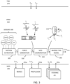
- FIG. 1 illustrates an example vehicle 100 for cargo transport where the herein disclosed techniques can be applied with advantage.
- the vehicle 100 comprises a tractor or towing vehicle 110 supported on front wheels 150 and rear wheels 160, at least some of which are driven wheels. Normally but not necessarily, all the wheels on the tractor are braked wheels.
- the tractor 110 is configured to tow a first trailer unit 120 supported on trailer wheels 170 by a fifth wheel connection in a known manner.
- the trailer wheels are normally braked wheels but may also comprise driven wheels on one or more axles.
- the tractor 110 comprises a vehicle unit computer (VUC) 130 for controlling various kinds of functionality, i.a. to achieve propulsion, braking, and steering.
- VUC vehicle unit computer
- Some trailer units 120 also comprise a VUC 140 for controlling various functions of the trailer, such as braking of trailer wheels, and sometimes also trailer wheel propulsion.
- the VUCs 130, 140 may be centralized or distributed over several processing circuits. Parts of the vehicle control functions may also be executed remotely, e.g., on a remote server 190 connected to the vehicle 100 via wireless link 180 and a wireless access network 185.
- the VUC 130 on the tractor 110 may be configured to execute vehicle control methods which are organized according to a layered functional architecture where some functionality may be comprised in a traffic situation management (TSM) domain in a higher layer and some other functionality may be comprised in a vehicle motion management (VMM) domain residing in a lower functional layer.
- TSM traffic situation management
- VMM vehicle motion management
- FIG. 2 schematically illustrates functionality 200 for controlling a wheel 210 by some example MSDs here comprising a friction brake 220 (such as a disc brake or a drum brake) and a propulsion device 250.
- the friction brake 220 and the propulsion device are examples of wheel torque generating devices, which may also be referred to as actuators and which can be controlled by one or more motion support device control units 230.
- the control is based on, e.g., measurement data obtained from a wheel speed sensor 240 and from other vehicle state sensors 280, such as radar sensors, lidar sensors, and also vision based sensors such as camera sensors and infra-red detectors.
- Other example torque generating motion support devices which may be controlled according to the principles discussed herein comprise engine retarders and power steering devices.
- An MSD control unit 230 may be arranged to control one or more actuators. For instance, it is not uncommon that an MSD control unit 230 is arranged to control both wheels on an axle.
- the TSM function 270 plans driving operation with a time horizon of, e.g., 10 seconds or so. This time frame corresponds to, e.g., the time it takes for the vehicle 100 to negotiate a curve.
- the vehicle maneuvers, planned and executed by the TSM can be associated with acceleration profiles and curvature profiles which describe a desired vehicle velocity and turning for a given maneuver.
- the TSM continuously requests the desired acceleration profiles a req and curvature profiles c req from the VMM function 260 which performs force allocation to meet the requests from the TSM in a safe and robust manner.
- the VMM function 260 continuously feeds back capability information to the TSM function detailing the current capability of the vehicle in terms of, e.g., forces, maximum velocities, and accelerations which can be generated.
- Acceleration profiles and curvature profiles may also be obtained from a driver of the heavy duty vehicle via normal control input devices such as a steering wheel, accelerator pedal and brake pedal.
- the source of said acceleration profiles and curvature profiles is not within scope of the present invention and will therefore not be discussed in more detail herein.
- the VMM function 260 operates with a time horizon of about 1 second or so, and continuously transforms the acceleration profiles a req and curvature profiles c req into control commands for controlling vehicle motion functions, actuated by the different MSDs 220, 250 of the vehicle 100 which report back capabilities to the VMM, which in turn are used as constraints in the vehicle control.
- the VMM function 260 performs vehicle state or motion estimation 305, i.e., the VMM function 260 continuously determines a vehicle state s comprising positions, speeds, accelerations and articulation angles of the different units in the vehicle combination by monitoring operations using various sensors 306 arranged on the vehicle 100, often but not always in connection to the MSDs 220, 250.
- the required global force vector V is input to an MSD coordination function 320 which allocates wheel forces and coordinates other MSDs such as steering and suspension.
- the coordinated MSDs then together provide the desired lateral Fy and longitudinal Fx forces on the vehicle units, as well as the required moments Mz, to obtain the desired motion by the vehicle combination 100.
- vehicle unit motion By determining vehicle unit motion using, e.g., global positioning systems, vision-based sensors, wheel speed sensors, radar sensors and/or lidar sensors, and translating this vehicle unit motion into a local coordinate system of a given wheel 210 (in terms of, e.g., longitudinal and lateral velocity components), it becomes possible to accurately estimate wheel slip in real time by comparing the vehicle unit motion in the wheel reference coordinate system to data obtained from the wheel speed sensor 240 arranged in connection to the wheel 210.
- a local coordinate system of a given wheel 210 in terms of, e.g., longitudinal and lateral velocity components
- a tyre model which will be discussed in more detail in connection to Figure 4 below, can be used to translate between a desired longitudinal tyre force Fx i for a given wheel i and an equivalent wheel slip ⁇ i for the wheel.
- Wheel slip ⁇ relates to a difference between wheel rotational velocity and speed over ground and will be discussed in more detail below.
- Wheel speed ⁇ is a rotational speed of the wheel, given in units of, e.g., rotations per minute (rpm) or angular velocity in terms radians/second (rad/sec) or degrees/second (deg/sec).
- a tyre model is a model of wheel behavior which describes wheel force generated in longitudinal direction (in the rolling direction) and/or lateral direction (orthogonal to the longitudinal direction) as function of wheel slip.
- Hans Pacejka covers the fundamentals of tyre models. See, e.g., chapter 7 where the relationship between wheel slip and longitudinal force is discussed.
- the VMM function 260 manages both force generation and MSD coordination, i.e., it determines what forces that are required at the vehicle units in order to fulfil the requests from the TSM function 270, for instance to accelerate the vehicle according to a requested acceleration profile requested by TSM and/or to generate a certain curvature motion by the vehicle also requested by TSM.
- the forces may comprise e.g., yaw moments Mz, longitudinal forces Fx and lateral forces Fy, as well as different types of torques to be applied at different wheels.
- the interface 265 between VMM and MSDs capable of delivering torque to the vehicle's wheels has, traditionally, been focused on torque based requests to each MSD from the VMM without any consideration towards wheel slip.
- this approach has significant performance limitations.
- a relevant safety function traction control, anti-lock brakes, etc. operated on a separate control unit normally steps in and requests a torque override in order to bring the slip back into control.
- ECUs electronice control units
- the latencies involved in the communication between them significantly limits the slip control performance.
- the related actuator and slip assumptions made in the two ECUs that are used to achieve the actual slip control can be inconsistent and this in turn can lead to sub-optimal performance.
- the inverse tyre model block 330 translates the required wheel forces Fx i , Fy i determined for each wheel, or for a subset of wheels, by the MSD coordination block 320 into equivalent wheel speeds ⁇ wi or wheel slips ⁇ i . These wheel speeds or slips are then sent to the respective MSD controllers 230.
- the MSD controllers report back capabilities 231a-231c which can be used as constraints in, e.g., the MSD coordination block 320.
- ⁇ is bounded between -1 and 1 and quantifies how much the wheel is slipping with respect to the road surface.
- Wheel slip is, in essence, a speed difference measured between the wheel and the vehicle.
- the herein disclosed techniques can be adapted for use with any type of wheel slip definition. It is also appreciated that a wheel slip value is equivalent to a wheel speed value given a velocity of the wheel over the surface, in the coordinate system of the wheel.
- the VMM 260 and optionally also the MSD control unit 230 maintains information on v x (in the reference frame of the wheel), while a wheel speed sensor 240 or the like can be used to determine ⁇ x (the rotational velocity of the wheel).
- a tyre 210 is subject to a longitudinal force F x , a lateral force F y , and a normal force F z .
- the normal force F z is key to determining some important vehicle properties. For instance, the normal force to a large extent determines the achievable lateral tyre force F y by the wheel since, normally, F y ⁇ ⁇ F z , where ⁇ is a friction coefficient associated with a road friction condition.
- the maximum available lateral force for a given lateral slip can be described by the so-called Magic Formula as described in " Tyre and vehicle dynamics", Elsevier Ltd. 2012, ISBN 978-0-08-097016-5, by Hans Pacejka .
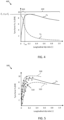
- Figure 4 is a graph showing an example of achievable tyre force as function of wheel slip.
- the longitudinal tyre force Fx shows an almost linearly increasing part 410 for small wheel slips, followed by a part 420 with more non-linear behaviour for larger wheel slips.
- the obtainable lateral tyre force Fy decreases rapidly even at relatively small longitudinal wheel slips. It is desirable to maintain vehicle operation in the linear region 410, where the obtainable longitudinal force in response to an applied brake command is easier to predict, and where enough lateral tyre force can be generated if needed.
- a wheel slip limit ⁇ LIM on the order of, e.g., 0.1, can be imposed on a given wheel.
- This type of tyre model can be used by the VMM 260 to generate a desired tyre force at some wheel. Instead of requesting a torque corresponding to the desired tyre force, the VMM can translate the desired tyre force into an equivalent wheel slip (or, equivalently, a wheel speed relative to a speed over ground) and request this slip instead.
- the main advantage being that the MSD control device 230 will be able to deliver the requested torque with much higher bandwidth by maintaining operation at the desired wheel slip, using the vehicle speed v x and the wheel rotational velocity ⁇ x .
- the control unit 130, 140 can be arranged to store a pre-determined inverse tyre model f -1 in memory, e.g., as a look-up table.
- the inverse tyre model is arranged to be stored in the memory as a function of the current operating condition of the wheel 210. This means that the behavior of the inverse tyre model is adjusted in dependence of the operating condition of the vehicle, which means that a more accurate model is obtained compared to one which does not account for operating condition.
- the model which is stored in memory can be determined based on experiments and trials, or based on analytical derivation, or a combination of the two. For instance, the control unit can be configured to access a set of different models which are selected depending on the current operating conditions.
- One inverse tyre model can be tailored for high load driving, where normal forces are large, another inverse tyre model can be tailored for slippery road conditions where road friction is low, and so on.
- the selection of a model to use can be based on a pre-determined set of selection rules.
- the model stored in memory can also, at least partly, be a function of operating condition.
- the model may be configured to take, e.g., normal force or road friction as input parameters, thereby obtaining the inverse tyre model in dependence of a current operating condition of the wheel 210. It is appreciated that many aspects of the operating conditions can be approximated by default operating condition parameters, while other aspects of the operating conditions can be roughly classified into a smaller number of classes.
- obtaining the inverse tyre model in dependence of a current operating condition of the wheel 210 does not necessarily mean that a large number of different models need to be stored, or a complicated analytical function which is able to account for variation in operating condition with fine granularity. Rather, it may be enough with two or three different models which are selected depending on operating condition. For instance, one model to be used when the vehicle is heavily loaded and another model to be used otherwise. In all cases, the mapping between tyre force and wheel slip changes in some way in dependence of the operating condition, which improves the precision of the mapping.
- the inverse tyre model may also be implemented at least partly as an adaptive model configured to automatically or at least semi-automatically adapt to the current operating conditions of the vehicle. This can be achieved by constantly monitoring the response of a given wheel in terms of wheel force generated in response to a given wheel slip request, and/or monitoring the response of the vehicle 100 in response to the wheel slip requests. The adaptive model can then be adjusted to more accurately model the wheel forces obtained in response to a given wheel slip request from a wheel.
- Figure 5 is a graph 500 illustrating an inverse tyre model which maps longitudinal tyre force Fx to wheel slip. Measurements 510 of pairs (F, ⁇ ) of wheel slip with corresponding tyre force F are also plotted.
- the control units disclosed herein are arranged to adapt the inverse tyre model f -1 based on a measured wheel behavior and/or vehicle behavior in response to the control of the heavy duty vehicle 100 based on the equivalent wheel speed or wheel slip.
- One such type of measurement is the resistance encountered by an electric machine when trying to generate a particular wheel speed. This "torque status" output signal of the electric machine can be directly translated into an equivalent wheel force via the effective wheel radius R.
- the wheel force samples can also be obtained from the VMM function as part of the force allocation process. For instance, if the VMM notes that a too small longitudinal force is consistently obtained in response to a given requested wheel slip, then the model can be adjusted to account for the discrepancy, e.g., by scaling it to better match the desired wheel forces.
- the inverse tyre model need not be correct in an absolute frame of reference, i.e., that the inverse tyre model is able to exactly predict the generated force in Newton for a given wheel slip. Rather, it is enough if the inverse tyre model is such as to allow successful control of the vehicle by the VMM function 260.
- the inverse tyre model in this manner based on measured wheel force in response to wheel slip requests, other characteristics of the vehicle will automatically be included in the modelling to more accurately represent the mapping between wheel slip and wheel force.
- sample pairs (F, ⁇ ) of generated force F vs current wheel slip ⁇ are continuously obtained.
- Generated force F both longitudinal Fx and lateral Fy
- yaw moments Mz can be determined based on vehicle behavior, i.e., Newtons second law type of relationships, where both mass m and accelerations a are possible to measure using basic sensor technology together with current wheel slip.
- the inverse tyre model is then continuously updated to fit the current measurement results. For instance, a Kalman filter can be applied to track coefficients ⁇ c i ⁇ of a polynomial model which can then be used as inverse tyre model. A polynomial fit can also be made to fit measurement data 510 to a model, which model can then be used as the inverse tyre model.
- a neural network or other form of Al-based method is applied to continuously update the inverse tyre model.
- the network is trained, e.g., using the sample pairs (F, ⁇ ) of generated force F vs current wheel slip ⁇ .
- Input to the network can be, e.g., vehicle load, tyre specification, and road condition in terms of, e.g., friction.
- the output can be a set of coefficients for a polynomial model which can be used as a representation of the inverse tyre model.
- this model adaptation does not need to be performed on-board the vehicle 100. Rather, measurement data can be uploaded to the remote server 190 which can be tasked with finding a suitable model for controlling the vehicle based on wheel slip instead of based on torque request. This model can then account for measurement data from more than one vehicle, perhaps from a set of vehicles of the same type, or operational design domain. The model or sets of models can then be fed back from the remote server 190 to the vehicle to be used in control of the vehicle 100.
- the whole inverse tyre model can of course also be realized as a neural network which is trained during different types of operating conditions. Then, as the operating conditions of the heavy duty vehicle changes, the inverse tyre model also changes such that the corresponding wheel slip for a given wheel force changes over time, which is an advantage.
- the inverse tyre model f -1 can also be adjusted to always lie within pre-determined upper and lower limits on wheel force in dependence of wheel slip or wheel speed. These limits may, e.g., be obtained as statistical limits derived from the measurement data 510. For instance, the upper and lower limits 520, 530 may be set so as to limit the inverse tyre model within one or two stand deviations from the mean, or the like.
- Safety margins can also be applied to the adaptation itself, i.e., a constrained adaptation can be performed where the inverse tyre model is not permitted to deviate outside of a fenced region around some nominal model curve.
- This fenced region can be pre-determined or adjusted in accordance with operating condition, or by pre-defined dynamic driving tasks (DDTs) on known operational design domains (ODDs) which will reduce the required amount of verification and validation.
- DDTs dynamic driving tasks
- ODDs operational design domains
- the MSD control unit 230 can be configured to control one or more MSDs associated with the wheel 210.
- the one or more MSDs may comprise at least one service brake 220 arranged to generate negative torque by the wheel 210, as well as propulsion units 250 arranged to generate a positive and/or a negative torque by the wheel 210, such as electric machines and/or a combustion engine.
- Other torque generating devices which may be controlled by an MSD control unit comprises engine retarders and power steering devices.
- the MSD control unit 230 is communicatively coupled to the VMM unit 260 for receiving control commands from the VMM unit 260 comprising wheel speed and/or wheel slip requests to control vehicle motion by the one or more MSDs.
- the MSD control units discussed herein may also be configured to control one or more MSDs associated with other wheels, in addition to the wheel 210, such as MSDs for controlling wheels of a given axle, or the wheels on one side of a trailer unit, or all wheels of a trailer unit.
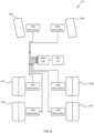
- a system of MSD control units 230a-230f arranged to control respective wheels 210a-210f based on control signals received from a central VMM unit 260 is schematically illustrated in Figure 6 .
- One or more additional vehicle units such as one or more trailers 120, possibly connected via dolly vehicle units, can also be controlled in this manner. In this case there may be more than one VMM function, where one VMM function can be assigned a master role and other VMM functions can be configured to operate in slave mode.
- the VMM function 260 performs force allocation to meet a certain acceleration profile and/or curvature profile.
- the forces are converted into equivalent wheel slip (or wheel rotational speed) and the slip or speed is sent to the MSD control unit 230 instead of a classical torque request.
- the conversion from desired force to equivalent slip or wheel rotational speed is performed based on an inverse tyre model f -1 ().
- This inverse tyre model is not only a function of the requested wheel torque or wheel force, but also accounts for the current operating scenario in which the vehicle 100 is currently operating.
- the tyre stiffness C est may be an estimated tyre stiffness that can be corrected for factors like tyre wear, age, temperature, inflation pressure, etc. This can either be only the longitudinal slip stiffness which can be used as a basis to scale the lateral slip stiffness of a given tyre or a vector comprising both the longitudinal slip stiffness and the lateral slip stiffness of the tyre. Tyre stiffness may have a significant impact on the force to slip curve 400. Without this argument, a nominal stiffness of the tyre can be used in the tyre model.
- the estimated friction, ⁇ est can be used to adapt the tyre force curve 400 to limit the peak force allowed and also to change the peak force slip position in the model. Without this optional input, a nominal dry asphalt tyre force curve can be used.
- the minimum required lateral force capacity F y,min and maximum allowed lateral slip angle limit ⁇ max are optional constraints to the tyre model which can be communicated via an interface like the interface 265 between the VMM function 260 and the various MSD control units 230. With these additional inputs, the generated longitudinal slip request is limited to a vector space where a lateral force capacity of F y,min is guaranteed using a maximum lateral slip angle of ⁇ max . Both these optional arguments can be used to request longitudinal force in a safe manner that does not cause significant yaw instability or the like. F y,min can be used to ensure that enough lateral force capacity remains to be able to take a particular corner or complete some other manoeuvre requiring the generation of lateral force (i.e.
- ⁇ max can be used to ensure that the yaw moment balance or the side-slip of the vehicle is maintained within reasonable pre-configured or dynamically determined limits. This feature may be of particular benefit in autonomous or functional safety critical applications where it is desired to keep the tyres operating in their linear combined-slip range (such as the range 410 shown in Figure 3 ) and therefore preventing any traction control or yaw stability interventions.
- ⁇ req is a wheel speed request and this is the primary request from the tyre model which should result in the required T req as long it is possible to do so given ⁇ est and without violating the F y,min and ⁇ max constraints.
- a wheel speed request ⁇ req can be continuously updated over time in dependence of the speed over ground v x , v y so as to be equivalent with a wheel slip, e.g., as defined in the wheel slip equation discussed above.
- a wheel slip value ⁇ req can be communicated instead of the wheel speed value. Given wheel speed over ground, wheel slip and wheel speed are equivalent information quantities.
- the remaining lateral force capacity F y,rem can be used to adjust bounds on the requests being sent or as feedback to the control allocator to adapt its control requests to increase F y,rem , e.g., if it goes too close to zero.
- dF x / d ⁇ and dF y / d ⁇ represent the gradient of the longitudinal and lateral forces w.r.t the wheel rotational speed ⁇ tgt at the requested operating point.
- These parameters can, e.g., be used to custom tune the gains to the speed controller in the actuator depending on the priority of control allocator. For instance, if the vehicle is cornering and the dF y / d ⁇ value is high, it indicates that poor speed control performance can degrade the lateral cornering performance and hence the gains for the speed controller can be adapted to prevent this.
- Another alternative is to simply send all the tyre parameters as a single structural argument (e.g., p tyre ) with a predetermined layout. Any values in the fields of the structure can be used to update the existing values whereas default values can be used in place of non-existing fields.
- ⁇ req ⁇ ⁇ ⁇ ⁇ ⁇ ⁇ ⁇ ⁇ ⁇ ⁇ ⁇ ⁇ ⁇ ⁇ ⁇ ⁇ ⁇ ⁇ ⁇ ⁇ ⁇ ⁇ ⁇ ⁇ ⁇ ⁇ ⁇ ⁇ ⁇ ⁇ ⁇ ⁇ ⁇ ⁇ ⁇ ⁇ ⁇ ⁇ ⁇ ⁇ ⁇ ⁇ ⁇ ⁇ ⁇ ⁇ ⁇ ⁇ ⁇ ⁇ ⁇ ⁇ ⁇ f ⁇ 1 F x , req F y , req v x v y F z , act p tyre F y , min ⁇ max
- wheel rotation speed ⁇ req i.e., the speed at which a given wheel 210 rotates
- wheel slip ⁇ the speed at which a given wheel 210 rotates
- control unit 130, 140 for controlling a heavy duty vehicle 100.
- the control unit is arranged to obtain input data indicative of a desired wheel force Fx, Fy to be generated by at least one wheel 210 of the vehicle 100, and to translate the input data into a respective equivalent wheel speed or wheel slip to be maintained by the wheel 210 to generate the desired wheel force Fx, Fy based on an inverse tyre model f -1 for the wheel 210.
- the input data indicative of the desired wheel force to be generated may, for instance, be obtained from a force allocation process where the necessary forces to make the vehicle follow a desired acceleration profile and/or a desired curvature are determined.
- the acceleration profile and curvature may be obtained from manual control inputs by a driver of the vehicle 100, or from autonomous or semi-autonomous control algorithms running on a VUC.
- the desired wheel forces may also at least in part be obtained from a remote server 190 via wireless link.
- the data indicative of the desired wheel force Fx, Fy may comprise a desired wheel torque Treq and a wheel rolling radius R.
- the control unit 130, 140 is arranged to obtain the inverse tyre model in dependence of a current operating condition of the wheel 210, and also arranged to control the heavy duty vehicle 100 based on the equivalent wheel speed or wheel slip.
- the control unit is configured to adapt the inverse tyre mode to the current operating conditions of the vehicle in some way. For instance, if the vehicle is loaded with heavy weight cargo, then the inverse tyre model used to control the vehicle is adjusted to account for the change in operating condition.
- Various types of operating condition parameters may be considered, as will be discussed in the following.
- the inverse tyre models considered herein are dynamic models which, different from constant models, are adapted to fit the current operating conditions of the heavy duty vehicle. This improves both vehicle performance and safety.
- the current operating condition may comprise a vehicle or wheel speed over ground vector with components v x , v y .
- This vehicle speed over ground can be used to determine a wheel rotational velocity corresponding to a given amount of slip, e.g., by computing the normalized wheel slip difference discussed above.
- Some tyres also behave a bit differently depending on if the wheel is rotating slowly or faster.
- some inverse tyre models may exhibit differences over an operating speed range from, e.g., 0 km/h over ground to say 150 km/h. It is appreciated that wheel control based on requested wheel rotational velocities requires a relatively fast interface between VMM function 260 and the MSD control unit 230. This is because the wheel rotational velocity required to obtain a given wheel slip depends on the velocity over ground, which may change relatively fast over time.
- the current operating condition optionally also comprises a normal load Fz or vertical tyre force associated with the wheel 210.
- the normal load may have a significant effect on the inverse tyre model, i.e., the mapping between desired wheel force and wheel speed or wheel slip.
- the maximum available longitudinal tyre force Fx is limited by the normal force and friction coefficient.
- the current operating condition comprises an estimated tyre stiffness Cest of the wheel 210. If the tyre stiffness is explicitly estimated, then a more accurate inverse tyre model can be obtained.
- the tyre stiffness may, e.g., be estimated based on a feedback system, where measurements of tyre force is mapped against wheel slip, and a linear or semi-linear relationship can be determined.
- the tyre stiffness can also be obtained, e.g., from a database maintained in the remote server 190 or in a memory connected to the VUC, which can be indexed if the tyre can be identified. Identifying a tyre attached to a given wheel can, e.g., be done by embedding a radio frequency identification (RFID) device into the tyre, or by manual configuration.
- RFID radio frequency identification
- the current operating conditions may furthermore comprise an estimated tyre road friction coefficient ⁇ of the wheel.
- This road friction can be estimated in real time using known methods, such as those disclosed in, e.g., US 9,475,500 B2 , US 8,983,749 B1 or EP 1719676 B1 .
- the inverse tyre model can then be adapted to match the current road friction.
- the current operating condition may furthermore comprise a minimum required lateral force capacity Fy,min and/or a maximum allowed lateral slip ⁇ of the wheel 210 of the wheel 210.
- the minimum lateral force capacity Fy,min and maximum lateral slip angle limit ⁇ are optional constraints to the tyre model. If this data is taken as input to the inverse tyre model function, then the output can be determined with these parameters as constraints. For instance, it can be ascertained that output wheel speeds or wheel slips are not such as to generate an insufficient lateral force capability, or lateral slip, which is an advantage.
- the inverse tyre model f -1 can also be configured to provide a remaining lateral force capacity Fy,rem of the wheel 210.
- the remaining lateral force capacity Fy,rem can be used to adjust bounds on the requests being sent or as feedback to the control allocator to adapt its control requests to increase remaining lateral force capacity if it becomes too low.
- the inverse tyre model f -1 can also be configured to provide a gradient of the desired wheel force dFx, dFy with respect to wheel speed or wheel slip at a tyre operating point associated with the desired wheel force and the current operating condition of the wheel 210.
- the gradient provides information about the behavior of the model if a small change in input parameters is made, and can be used with advantage to adjust control algorithms in, e.g., the MSD control units 230.
- the gradients can be used to adjust a gain of a control function such as a PID controller.
- FIG. 7 is a flow chart illustrating methods which summarize at least some of the discussions above. There is illustrated a method performed in a control unit 130, 140 for controlling a heavy duty vehicle 100. The method comprises obtaining S1 input data indicative of a desired wheel force Fx, Fy to be generated by at least one wheel 210 of the vehicle 100, and obtaining S2 an inverse tyre model f -1 associated with the wheel 210, wherein the inverse tyre model in dependence of a current operating condition of the wheel 210.
- the method further comprises translating S3 the input data into a respective equivalent wheel speed or wheel slip to be maintained by the wheel 210 to generate the desired wheel force Fx, Fy based on an inverse tyre model for the wheel 210, and controlling S4 the heavy duty vehicle 100 based on the equivalent wheel speed or wheel slip.
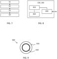
- FIG. 8 schematically illustrates, in terms of a number of functional units, the components of a control unit such as the VUC 130, 140.
- the control unit may implement one or more of the above discussed functions of the TSM 270, VMM 260 and/or the MSD control function 230, according to embodiments of the discussions herein.
- the control unit is configured to execute at least some of the functions discussed above for control of a heavy duty vehicle 100.
- Processing circuitry 810 is provided using any combination of one or more of a suitable central processing unit CPU, multiprocessor, microcontroller, digital signal processor DSP, etc., capable of executing software instructions stored in a computer program product, e.g. in the form of a storage medium 820.
- the processing circuitry 810 may further be provided as at least one application specific integrated circuit ASIC, or field programmable gate array FPGA.
- the processing circuitry 810 is configured to cause the control unit 101 to perform a set of operations, or steps, such as the methods discussed in connection to Figure 7 .
- the storage medium 820 may store the set of operations
- the processing circuitry 810 may be configured to retrieve the set of operations from the storage medium 820 to cause the control unit 900 to perform the set of operations.
- the set of operations may be provided as a set of executable instructions.
- the processing circuitry 810 is thereby arranged to execute methods as herein disclosed.
- the storage medium 820 may also comprise persistent storage, which, for example, can be any single one or combination of magnetic memory, optical memory, solid state memory or even remotely mounted memory.
- the control unit 900 may further comprise an interface 830 for communications with at least one external device.
- the interface 830 may comprise one or more transmitters and receivers, comprising analogue and digital components and a suitable number of ports for wireline or wireless communication.
- the processing circuitry 810 controls the general operation of the control unit 900, e.g., by sending data and control signals to the interface 830 and the storage medium 820, by receiving data and reports from the interface 830, and by retrieving data and instructions from the storage medium 820.
- Other components, as well as the related functionality, of the control node are omitted in order not to obscure the concepts presented herein.
- Figure 9 illustrates a computer readable medium 910 carrying a computer program comprising program code means 920 for performing the methods illustrated in Figure 7 , when said program product is run on a computer.
- the computer readable medium and the code means may together form a computer program product 900.
Landscapes
- Engineering & Computer Science (AREA)
- Transportation (AREA)
- Mechanical Engineering (AREA)
- Automation & Control Theory (AREA)
- Physics & Mathematics (AREA)
- Chemical & Material Sciences (AREA)
- Combustion & Propulsion (AREA)
- Mathematical Physics (AREA)
- Fluid Mechanics (AREA)
- Microelectronics & Electronic Packaging (AREA)
- Human Computer Interaction (AREA)
- Electric Propulsion And Braking For Vehicles (AREA)
- Control Of Driving Devices And Active Controlling Of Vehicle (AREA)
- Regulating Braking Force (AREA)
- Control Of Vehicle Engines Or Engines For Specific Uses (AREA)
- Steering-Linkage Mechanisms And Four-Wheel Steering (AREA)
- Vehicle Body Suspensions (AREA)
Claims (20)
- Unité de commande (130, 140) pour commander un véhicule lourd (100),dans laquelle l'unité de commande est disposée de manière à obtenir des données d'entrée indicatives d'une force de roue souhaitée (Fx, Fy) devant être générée par au moins une roue (210) du véhicule (100), etpour traduire les données d'entrée en une vitesse de roue ou un patinage de roue équivalent respectif destiné à être maintenu par la roue (210) pour générer la force de roue souhaitée (Fx, Fy) sur la base d'un modèle de pneu inversé (f-1) pour la roue (210),dans laquelle l'unité de commande (130, 140) est disposée de manière à obtenir le modèle de pneu inversé en fonction d'une condition de fonctionnement actuelle de la roue (210), et dans laquelle l'unité de commande (130, 140) est disposée de manière à commander le véhicule lourd (100) sur la base de la vitesse de roue ou du patinage de roue équivalent, etcaractérisée en ce quedans laquelle la commande du véhicule lourd (100) sur la base de la vitesse de roue ou du patinage de roue équivalent comprend l'envoi d'une demande pour la vitesse de roue ou le patinage de roue équivalent à un dispositif de commande d'aide au mouvement (230).
- Unité de commande (130, 140) selon la revendication 1, dans laquelle l'unité de commande est également disposée de manière à attribuer un angle de braquage (δreg) à une ou plusieurs roues directrices.
- Unité de commande (130, 140) selon la revendication 1 ou 2, dans laquelle les données indicatives de la force de roue souhaitée (Fx, Fy) comprennent un couple de roue souhaité (Treq) et un rayon de roulement de roue (R).
- Unité de commande (130, 140) selon une quelconque revendication précédente, dans laquelle la condition de fonctionnement actuelle comprend une répartition de force au niveau du véhicule (Fx, Fy, Mz) et/ou un vecteur de vitesse des roues sur le sol (Vx, Vy).
- Unité de commande (130, 140) selon une quelconque revendication précédente, dans laquelle la condition de fonctionnement actuelle comprend une charge normale (Fz) de la roue (210).
- Unité de commande (130, 140) selon une quelconque revendication précédente, dans laquelle la condition de fonctionnement actuelle comprend une rigidité estimée du pneu (Cest) de la roue (210).
- Unité de commande (130, 140) selon une quelconque revendication précédente, dans laquelle la condition de fonctionnement actuelle comprend un coefficient de friction du pneu sur route (µ) associé à la roue.
- Unité de commande (130, 140) selon une quelconque revendication précédente, dans laquelle la condition de fonctionnement actuelle comprend une capacité de force latérale minimale requise (Fy, min) de la roue (210).
- Unité de commande (130, 140) selon une quelconque revendication précédente, dans laquelle la condition de fonctionnement actuelle comprend un angle de dérapage latéral maximum autorisé (α) de la roue (210).
- Unité de commande (130, 140) selon une quelconque revendication précédente, dans laquelle le modèle de pneu inversé (f-1) est configuré pour fournir une capacité de force latérale restante (Fy, rem) de la roue (210).
- Unité de commande (130, 140) selon une quelconque revendication précédente, dans laquelle le modèle de pneu inversé (f-1) est configuré pour fournir un gradient de la force de roue souhaitée (dFx, dFy) par rapport à la vitesse de roue ou au patinage de roue à un point de fonctionnement du pneu associé avec la force de roue souhaitée et la condition de fonctionnement actuelle de la roue (210).
- Unité de commande (130, 140) selon une quelconque revendication précédente, dans laquelle l'unité de commande est disposée de manière à stocker en mémoire un modèle de pneu inversé prédéterminé (f-1), dans laquelle le modèle de pneu inversé est stocké dans la mémoire en fonction de la condition de fonctionnement actuelle de la roue (210).
- Unité de commande (130, 140) selon une quelconque revendication précédente, dans laquelle l'unité de commande est disposée de manière à adapter le modèle de pneu inversé (f-1) sur la base d'un comportement mesuré de la roue et/ou d'un comportement du véhicule en réponse à la commande du véhicule lourd (100) sur la base de la vitesse de roue ou du patinage de roue équivalent.
- Unité de commande (130, 140) selon la revendication 13, dans laquelle le modèle de pneu inversé (f-1) est ajusté pour toujours se situer dans des limites supérieures et/ou inférieures prédéterminées de la force de roue en fonction de la vitesse de roue ou du patinage de roue.
- Unité de commande (130, 140) selon une quelconque revendication précédente, dans laquelle l'unité de commande est disposée de manière à représenter le modèle de pneu inversé (f-1) sous forme de table de correspondance.
- Unité de commande (130, 140) selon l'une quelconque des revendications 1 à 14, dans laquelle l'unité de commande est disposée de manière à représenter le modèle de pneu inversé (f-1) sous la forme d'un réseau neuronal.
- Véhicule (100) comprenant une unité de commande (130, 140) selon l'une quelconque des revendications 1 à 16.
- Procédé réalisé dans une unité de commande (130, 140) pour commander un véhicule lourd (100), le procédé comprenant l'obtention (S1) des données d'entrée indicatives d'une force de roue souhaitée (Fx, Fy) devant être générée par au moins une roue (210) du véhicule (100),l'obtention (S2) d'un modèle de pneu inversé (f-1) associé à la roue (210), le modèle de pneu inversé dépendant d'une condition de fonctionnement actuelle de la roue (210), et la traduction (S3) des données d'entrée en une vitesse de roue ou un patinage de roue équivalent respectif devant être maintenu par la roue (210) pour générer la force de roue souhaitée (Fx, Fy) sur la base d'un modèle de pneu inversé pour la roue (210), etla commande (S4) du véhicule lourd (100) sur la base de la vitesse de roue ou du patinage de roue équivalent, caractérisé en ce quela commande du véhicule lourd (100) sur la base de la vitesse de roue ou du patinage de roue équivalent comprend l'envoi d'une demande pour la vitesse de roue ou le patinage de roue équivalent à un dispositif de commande d'aide au mouvement (230).
- Programme informatique (920) comprenant des moyens de code de programme pour exécuter les étapes selon la revendication 18 lorsque ledit programme est exécuté sur un ordinateur ou sur un circuit de traitement (910) d'une unité de commande (900).
- Support lisible par ordinateur (910) portant un programme informatique (920) comprenant des moyens de code de programme pour exécuter les étapes selon la revendication 18 lorsque ledit produit programme est exécuté sur un ordinateur ou sur un circuit de traitement (910) d'une unité de commande (900).
Priority Applications (8)
| Application Number | Priority Date | Filing Date | Title |
|---|---|---|---|
| KR1020227028074A KR20220125810A (ko) | 2020-01-15 | 2020-12-04 | 스피드 리미트를 갖는 토크 요청에 기반하는 차량 모션 관리 |
| US17/758,679 US20230047444A1 (en) | 2020-01-15 | 2020-12-04 | Vehicle motion management based on torque request with speed limit |
| EP20816487.1A EP4090563A1 (fr) | 2020-01-15 | 2020-12-04 | Gestion de mouvement de véhicule sur la base d'une demande de couple avec limite de vitesse |
| CN202080093069.7A CN114945496A (zh) | 2020-01-15 | 2020-12-04 | 基于具有速度极限的扭矩请求的车辆运动管理 |
| PCT/EP2020/084597 WO2021144065A1 (fr) | 2020-01-15 | 2020-12-04 | Gestion de mouvement de véhicule sur la base d'une demande de couple avec limite de vitesse |
| JP2022542395A JP7508563B2 (ja) | 2020-01-15 | 2020-12-04 | 速度制限付きのトルク要求に基づく車両運動管理 |
| US17/450,523 US20220126799A1 (en) | 2020-01-15 | 2021-10-11 | Inverse tyre model for advanced vehicle motion management |
| CN202111181395.6A CN114454865A (zh) | 2020-01-15 | 2021-10-11 | 用于高级车辆运动管理的逆轮胎模型 |
Applications Claiming Priority (1)
| Application Number | Priority Date | Filing Date | Title |
|---|---|---|---|
| PCT/EP2020/050850 WO2021144010A1 (fr) | 2020-01-15 | 2020-01-15 | Procédés de réglage d'un véhicule utilitaire lourd en mouvement |
Publications (3)
| Publication Number | Publication Date |
|---|---|
| EP3851346A1 EP3851346A1 (fr) | 2021-07-21 |
| EP3851346C0 EP3851346C0 (fr) | 2023-11-22 |
| EP3851346B1 true EP3851346B1 (fr) | 2023-11-22 |
Family
ID=69185565
Family Applications (3)
| Application Number | Title | Priority Date | Filing Date |
|---|---|---|---|
| EP20701407.7A Pending EP4090561A1 (fr) | 2020-01-15 | 2020-01-15 | Procédés de réglage d'un véhicule utilitaire lourd en mouvement |
| EP20203293.4A Active EP3851346B1 (fr) | 2020-01-15 | 2020-10-22 | Modèle de pneu inverse pour la gestion avancée de mouvement de véhicule |
| EP20203236.3A Active EP3851345B1 (fr) | 2020-01-15 | 2020-10-22 | Gestion de mouvements de véhicule basé sur le glissement de roue pour des véhicules utilitaires lourds |
Family Applications Before (1)
| Application Number | Title | Priority Date | Filing Date |
|---|---|---|---|
| EP20701407.7A Pending EP4090561A1 (fr) | 2020-01-15 | 2020-01-15 | Procédés de réglage d'un véhicule utilitaire lourd en mouvement |
Family Applications After (1)
| Application Number | Title | Priority Date | Filing Date |
|---|---|---|---|
| EP20203236.3A Active EP3851345B1 (fr) | 2020-01-15 | 2020-10-22 | Gestion de mouvements de véhicule basé sur le glissement de roue pour des véhicules utilitaires lourds |
Country Status (6)
| Country | Link |
|---|---|
| US (3) | US20230339477A1 (fr) |
| EP (3) | EP4090561A1 (fr) |
| JP (2) | JP7411102B2 (fr) |
| KR (2) | KR20220122769A (fr) |
| CN (3) | CN114938644B (fr) |
| WO (1) | WO2021144010A1 (fr) |
Families Citing this family (22)
| Publication number | Priority date | Publication date | Assignee | Title |
|---|---|---|---|---|
| CN114728638B (zh) * | 2019-12-10 | 2024-07-05 | 沃尔沃卡车集团 | 用于控制车辆的辅助制动的方法 |
| EP4001030A1 (fr) * | 2020-11-16 | 2022-05-25 | Volvo Truck Corporation | Procédé de contrôle de patinage de roue d'un véhicule |
| EP4001029A1 (fr) | 2020-11-16 | 2022-05-25 | Volvo Truck Corporation | Système de gestion de mouvement de véhicule et système de commande d'actionneur pour un véhicule |
| JP7394095B2 (ja) * | 2021-09-17 | 2023-12-07 | 株式会社アドヴィックス | 車両運動制御装置 |
| CN117957153A (zh) * | 2021-09-21 | 2024-04-30 | 沃尔沃卡车集团 | 用于重型车辆的基于车轮滑移的运动控制 |
| EP4166368B1 (fr) | 2021-10-18 | 2024-03-27 | Volvo Truck Corporation | Fonction de renforcement du patinage des roues pour un véhicule lourd |
| WO2023098991A1 (fr) | 2021-12-01 | 2023-06-08 | Volvo Truck Corporation | Adaptation de modèle de pneu inverse en fonction de données de sortie de capteur d'aplatissement de bande de roulement de pneu |
| EP4190651A1 (fr) | 2021-12-02 | 2023-06-07 | Volvo Truck Corporation | Systèmes de commande de véhicule redondants basés sur des capteurs de pneu |
| EP4190598A1 (fr) * | 2021-12-02 | 2023-06-07 | Volvo Truck Corporation | Systèmes redondants de commande de véhicule basés sur des capteurs de pneu - estimation de charge |
| KR20240121756A (ko) | 2021-12-20 | 2024-08-09 | 볼보 트럭 코퍼레이션 | 대형 차량 모션 관리를 위한 강건 액추에이터 제어 방법 |
| WO2023117031A1 (fr) * | 2021-12-20 | 2023-06-29 | Volvo Truck Corporation | Gestion prédictive de mouvement de véhicule utilitaire lourd sur la base d'une détection d'environnement |
| CN118524957A (zh) | 2022-01-27 | 2024-08-20 | 沃尔沃卡车集团 | 重型车辆运动支持装置能力反馈 |
| WO2023160788A1 (fr) | 2022-02-24 | 2023-08-31 | Volvo Truck Corporation | Systèmes pour déterminer la vitesse d'un véhicule au sol |
| WO2023169652A1 (fr) | 2022-03-07 | 2023-09-14 | Volvo Truck Corporation | Systèmes radar pour la détermination de la vitesse d'un véhicule sur le sol |
| WO2023169702A1 (fr) | 2022-03-10 | 2023-09-14 | Volvo Truck Corporation | Roulement libre rapide de roues permettant une détermination robuste de vitesse par rapport au sol de véhicule |
| WO2023169701A1 (fr) | 2022-03-10 | 2023-09-14 | Volvo Truck Corporation | Estimation robuste de la vitesse au sol d'un véhicule au moyen de capteurs de vitesse de roue et d'unités de mesure inertielle |
| WO2023169681A1 (fr) | 2022-03-10 | 2023-09-14 | Volvo Truck Corporation | Système de capteurs pour déterminer la vitesse au sol d'un véhicule |
| EP4292889A1 (fr) * | 2022-06-13 | 2023-12-20 | KNORR-BREMSE Systeme für Nutzfahrzeuge GmbH | Procédé et appareil d'estimation d'un coefficient de frottement d'une roue de véhicule |
| WO2024012655A1 (fr) | 2022-07-11 | 2024-01-18 | Volvo Truck Corporation | Estimation améliorée de rayon de roulement effectif de roue |
| US20240166192A1 (en) * | 2022-11-21 | 2024-05-23 | GM Global Technology Operations LLC | Machine learning-based tractive limit and wheel stability status estimation |
| WO2024114885A1 (fr) | 2022-11-28 | 2024-06-06 | Volvo Truck Corporation | Système radar au sol de véhicule monté sur essieu |
| US20240208497A1 (en) * | 2022-12-27 | 2024-06-27 | Embark Trucks Inc. | Physics-based acceleration control node |
Family Cites Families (34)
| Publication number | Priority date | Publication date | Assignee | Title |
|---|---|---|---|---|
| US5269391A (en) * | 1990-02-27 | 1993-12-14 | Mitsubishi Jidosha Kogyo Kabushiki Kaisha | Apparatus for controlling the output of a vehicle equipped with an internal combustion engine |
| GB9209137D0 (en) * | 1992-04-28 | 1992-06-10 | Lucas Ind Plc | Method of and apparatus for estimating surface friction |
| JPH0820323A (ja) * | 1994-07-07 | 1996-01-23 | Mazda Motor Corp | 車両のアンチスキッドブレーキ装置 |
| JPH10194107A (ja) * | 1997-01-13 | 1998-07-28 | Aisin Seiki Co Ltd | 車両の加速スリップ制御装置 |
| JP3409736B2 (ja) * | 1999-04-30 | 2003-05-26 | 日産自動車株式会社 | 先行車追従制御装置 |
| DE19949220B4 (de) * | 1999-10-13 | 2010-04-08 | Robert Bosch Gmbh | Verfahren und Vorrichtung zur Steuerung der Antriebseinheit eines Fahrzeugs |
| JP3515040B2 (ja) * | 2000-03-09 | 2004-04-05 | 住友ゴム工業株式会社 | 路面摩擦係数判定方法 |
| DE10112351B4 (de) * | 2001-03-13 | 2016-03-03 | Continental Teves Ag & Co. Ohg | Verfahren zur Verbesserung des Regelverhaltens eines mit einem Blockierschutzregelungssystem ausgerüsteten Fahrzeugs |
| US20060253243A1 (en) | 2005-05-06 | 2006-11-09 | Jacob Svendenius | System and method for tire/road friction estimation |
| JP2007196705A (ja) * | 2006-01-23 | 2007-08-09 | Toyota Motor Corp | 車両用制動制御装置 |
| EP1840552B1 (fr) * | 2006-03-31 | 2012-05-02 | The Yokohama Rubber Co., Ltd. | Procédé de calcul de données de réponse transitoire des pneus, procédé de conception de pneus et procédé de prédiction des mouvements du véhicule |
| CN102157056B (zh) * | 2006-09-14 | 2012-12-05 | 克朗设备公司 | 用于远程控制物资处理车辆的系统和方法 |
| JP4416000B2 (ja) * | 2007-03-30 | 2010-02-17 | トヨタ自動車株式会社 | 駐車支援装置 |
| JP5050819B2 (ja) * | 2007-12-04 | 2012-10-17 | トヨタ自動車株式会社 | 車両運動制御システム |
| DE102007062203B4 (de) * | 2007-12-21 | 2010-07-15 | Continental Automotive Gmbh | Verfahren und Vorrichtung zum Ermitteln eines Reibwerts |
| JP5148393B2 (ja) * | 2008-07-10 | 2013-02-20 | 日立オートモティブシステムズ株式会社 | 車両用制駆動力制御装置 |
| CN202186297U (zh) * | 2011-07-08 | 2012-04-11 | 王德恒 | 一种电动车起步助力系统 |
| GB201210282D0 (en) | 2012-06-11 | 2012-07-25 | Jaguar Cars | Vehicle and method of control thereof |
| GB201308807D0 (en) | 2013-05-16 | 2013-07-03 | Jaguar Land Rover Ltd | Vehicle traction control |
| DE102013011230A1 (de) * | 2013-07-05 | 2015-01-08 | Audi Ag | Verfahren zur Verbesserung der Traktion von Fahrzeugen |
| JP2015030314A (ja) | 2013-07-31 | 2015-02-16 | 株式会社アドヴィックス | 車両制御装置 |
| JP6201209B2 (ja) | 2013-09-12 | 2017-09-27 | 日立オートモティブシステムズ株式会社 | 駆動力制御装置及び駆動力制御方法 |
| US8983749B1 (en) | 2013-10-24 | 2015-03-17 | The Goodyear Tire & Rubber Company | Road friction estimation system and method |
| AT515110B1 (de) * | 2014-01-09 | 2015-06-15 | Seibt Kristl & Co Gmbh | Verfahren und Einrichtung zur Regelung eines Antriebsstrang-Prüfstands |
| US9475500B2 (en) | 2014-11-12 | 2016-10-25 | GM Global Technology Operations LLC | Use of participative sensing systems to enable enhanced road friction estimation |
| US20170168500A1 (en) * | 2015-12-10 | 2017-06-15 | Uber Technologies, Inc. | System and method to determine traction ability of vehicles in operation |
| US9988026B2 (en) * | 2015-12-22 | 2018-06-05 | Autoliv-Nissin Brake Systems Japan Co., Ltd. | System and method for independently controlling wheel slip and vehicle acceleration |
| JP6869269B2 (ja) * | 2016-06-15 | 2021-05-12 | ボルボトラックコーポレーション | 車両の車輪制御装置 |
| EP3694766B1 (fr) | 2017-10-10 | 2021-11-24 | Volvo Truck Corporation | Procédé de commande du système de direction d'un véhicule |
| EP3707041A1 (fr) * | 2017-11-07 | 2020-09-16 | Hyster-Yale Group, Inc. | Commande de transmission variable en continu |
| US10882524B2 (en) * | 2018-02-09 | 2021-01-05 | Ford Global Technologies, Llc | Systems and methods for vehicle launch control |
| JP7114923B2 (ja) | 2018-02-16 | 2022-08-09 | スズキ株式会社 | 車両の制御装置 |
| JP6969440B2 (ja) * | 2018-02-26 | 2021-11-24 | トヨタ自動車株式会社 | 車両の運転支援装置 |
| US11161514B2 (en) * | 2019-09-12 | 2021-11-02 | Ford Global Technologies, Llc | System and method for coordinating independent axles for continuous wheel slip control |
-
2020
- 2020-01-15 JP JP2022542741A patent/JP7411102B2/ja active Active
- 2020-01-15 CN CN202080092633.3A patent/CN114938644B/zh active Active
- 2020-01-15 US US17/758,772 patent/US20230339477A1/en active Pending
- 2020-01-15 KR KR1020227027884A patent/KR20220122769A/ko active Search and Examination
- 2020-01-15 WO PCT/EP2020/050850 patent/WO2021144010A1/fr unknown
- 2020-01-15 EP EP20701407.7A patent/EP4090561A1/fr active Pending
- 2020-10-22 EP EP20203293.4A patent/EP3851346B1/fr active Active
- 2020-10-22 EP EP20203236.3A patent/EP3851345B1/fr active Active
-
2021
- 2021-10-11 JP JP2021166941A patent/JP2022068844A/ja active Pending
- 2021-10-11 US US17/450,518 patent/US20220126801A1/en active Pending
- 2021-10-11 US US17/450,523 patent/US20220126799A1/en active Pending
- 2021-10-11 CN CN202111181859.3A patent/CN114454866A/zh active Pending
- 2021-10-11 CN CN202111181395.6A patent/CN114454865A/zh active Pending
- 2021-10-21 KR KR1020210141078A patent/KR20220054209A/ko unknown
Also Published As
| Publication number | Publication date |
|---|---|
| US20220126799A1 (en) | 2022-04-28 |
| JP2023517445A (ja) | 2023-04-26 |
| KR20220054209A (ko) | 2022-05-02 |
| EP3851345C0 (fr) | 2024-05-22 |
| EP3851345B1 (fr) | 2024-05-22 |
| CN114454866A (zh) | 2022-05-10 |
| JP7411102B2 (ja) | 2024-01-10 |
| WO2021144010A1 (fr) | 2021-07-22 |
| CN114938644A (zh) | 2022-08-23 |
| EP3851346C0 (fr) | 2023-11-22 |
| EP4090561A1 (fr) | 2022-11-23 |
| EP3851345A1 (fr) | 2021-07-21 |
| CN114938644B (zh) | 2024-09-17 |
| JP2022068844A (ja) | 2022-05-10 |
| US20220126801A1 (en) | 2022-04-28 |
| US20230339477A1 (en) | 2023-10-26 |
| EP3851346A1 (fr) | 2021-07-21 |
| KR20220122769A (ko) | 2022-09-02 |
| CN114454865A (zh) | 2022-05-10 |
Similar Documents
| Publication | Publication Date | Title |
|---|---|---|
| EP3851346B1 (fr) | Modèle de pneu inverse pour la gestion avancée de mouvement de véhicule | |
| US20230047444A1 (en) | Vehicle motion management based on torque request with speed limit | |
| EP4140839A1 (fr) | Commande de véhicule basé sur une limite de dérapage configurée de manière dynamique | |
| EP4190598A1 (fr) | Systèmes redondants de commande de véhicule basés sur des capteurs de pneu - estimation de charge | |
| US20220410853A1 (en) | Method for controlling propulsion of a heavy-duty vehicle | |
| WO2023169701A1 (fr) | Estimation robuste de la vitesse au sol d'un véhicule au moyen de capteurs de vitesse de roue et d'unités de mesure inertielle | |
| WO2023098991A1 (fr) | Adaptation de modèle de pneu inverse en fonction de données de sortie de capteur d'aplatissement de bande de roulement de pneu | |
| US20240286615A1 (en) | A method for controlling propulsion of a heavy-duty vehicle | |
| US20240025267A1 (en) | Vehicle motion management system and motion support device control system | |
| EP4166368B1 (fr) | Fonction de renforcement du patinage des roues pour un véhicule lourd | |
| US20240182019A1 (en) | Vehicle control based on dynamically configured longitudinal wheel slip limits | |
| WO2023030615A1 (fr) | Commande de véhicule pour conduite autonome simplifiée |
Legal Events
| Date | Code | Title | Description |
|---|---|---|---|
| PUAI | Public reference made under article 153(3) epc to a published international application that has entered the european phase |
Free format text: ORIGINAL CODE: 0009012 |
|
| STAA | Information on the status of an ep patent application or granted ep patent |
Free format text: STATUS: THE APPLICATION HAS BEEN PUBLISHED |
|
| AK | Designated contracting states |
Kind code of ref document: A1 Designated state(s): AL AT BE BG CH CY CZ DE DK EE ES FI FR GB GR HR HU IE IS IT LI LT LU LV MC MK MT NL NO PL PT RO RS SE SI SK SM TR |
|
| STAA | Information on the status of an ep patent application or granted ep patent |
Free format text: STATUS: REQUEST FOR EXAMINATION WAS MADE |
|
| 17P | Request for examination filed |
Effective date: 20211220 |
|
| RBV | Designated contracting states (corrected) |
Designated state(s): AL AT BE BG CH CY CZ DE DK EE ES FI FR GB GR HR HU IE IS IT LI LT LU LV MC MK MT NL NO PL PT RO RS SE SI SK SM TR |
|
| GRAP | Despatch of communication of intention to grant a patent |
Free format text: ORIGINAL CODE: EPIDOSNIGR1 |
|
| STAA | Information on the status of an ep patent application or granted ep patent |
Free format text: STATUS: GRANT OF PATENT IS INTENDED |
|
| INTG | Intention to grant announced |
Effective date: 20230628 |
|
| GRAS | Grant fee paid |
Free format text: ORIGINAL CODE: EPIDOSNIGR3 |
|
| GRAA | (expected) grant |
Free format text: ORIGINAL CODE: 0009210 |
|
| STAA | Information on the status of an ep patent application or granted ep patent |
Free format text: STATUS: THE PATENT HAS BEEN GRANTED |
|
| AK | Designated contracting states |
Kind code of ref document: B1 Designated state(s): AL AT BE BG CH CY CZ DE DK EE ES FI FR GB GR HR HU IE IS IT LI LT LU LV MC MK MT NL NO PL PT RO RS SE SI SK SM TR |
|
| REG | Reference to a national code |
Ref country code: GB Ref legal event code: FG4D |
|
| RIN1 | Information on inventor provided before grant (corrected) |
Inventor name: RYDSTROEM, MATS Inventor name: LAINE, LEO Inventor name: RAY, SIDHANT Inventor name: HENDERSON, LEON Inventor name: FROEJD, NIKLAS Inventor name: ARIKERE, ADITHYA |
|
| REG | Reference to a national code |
Ref country code: CH Ref legal event code: EP Ref country code: DE Ref legal event code: R096 Ref document number: 602020021411 Country of ref document: DE |
|
| REG | Reference to a national code |
Ref country code: IE Ref legal event code: FG4D |
|
| U01 | Request for unitary effect filed |
Effective date: 20231214 |
|
| U07 | Unitary effect registered |
Designated state(s): AT BE BG DE DK EE FI FR IT LT LU LV MT NL PT SE SI Effective date: 20231221 |
|
| U1N | Appointed representative for the unitary patent procedure changed [after the registration of the unitary effect] |
Representative=s name: STROEM & GULLIKSSON AB; SE |
|
| PG25 | Lapsed in a contracting state [announced via postgrant information from national office to epo] |
Ref country code: GR Free format text: LAPSE BECAUSE OF FAILURE TO SUBMIT A TRANSLATION OF THE DESCRIPTION OR TO PAY THE FEE WITHIN THE PRESCRIBED TIME-LIMIT Effective date: 20240223 |
|
| PG25 | Lapsed in a contracting state [announced via postgrant information from national office to epo] |
Ref country code: IS Free format text: LAPSE BECAUSE OF FAILURE TO SUBMIT A TRANSLATION OF THE DESCRIPTION OR TO PAY THE FEE WITHIN THE PRESCRIBED TIME-LIMIT Effective date: 20240322 |
|
| PG25 | Lapsed in a contracting state [announced via postgrant information from national office to epo] |
Ref country code: ES Free format text: LAPSE BECAUSE OF FAILURE TO SUBMIT A TRANSLATION OF THE DESCRIPTION OR TO PAY THE FEE WITHIN THE PRESCRIBED TIME-LIMIT Effective date: 20231122 |
|
| PG25 | Lapsed in a contracting state [announced via postgrant information from national office to epo] |
Ref country code: IS Free format text: LAPSE BECAUSE OF FAILURE TO SUBMIT A TRANSLATION OF THE DESCRIPTION OR TO PAY THE FEE WITHIN THE PRESCRIBED TIME-LIMIT Effective date: 20240322 Ref country code: GR Free format text: LAPSE BECAUSE OF FAILURE TO SUBMIT A TRANSLATION OF THE DESCRIPTION OR TO PAY THE FEE WITHIN THE PRESCRIBED TIME-LIMIT Effective date: 20240223 Ref country code: ES Free format text: LAPSE BECAUSE OF FAILURE TO SUBMIT A TRANSLATION OF THE DESCRIPTION OR TO PAY THE FEE WITHIN THE PRESCRIBED TIME-LIMIT Effective date: 20231122 |
|
| PG25 | Lapsed in a contracting state [announced via postgrant information from national office to epo] |
Ref country code: RS Free format text: LAPSE BECAUSE OF FAILURE TO SUBMIT A TRANSLATION OF THE DESCRIPTION OR TO PAY THE FEE WITHIN THE PRESCRIBED TIME-LIMIT Effective date: 20231122 Ref country code: PL Free format text: LAPSE BECAUSE OF FAILURE TO SUBMIT A TRANSLATION OF THE DESCRIPTION OR TO PAY THE FEE WITHIN THE PRESCRIBED TIME-LIMIT Effective date: 20231122 Ref country code: NO Free format text: LAPSE BECAUSE OF FAILURE TO SUBMIT A TRANSLATION OF THE DESCRIPTION OR TO PAY THE FEE WITHIN THE PRESCRIBED TIME-LIMIT Effective date: 20240222 Ref country code: HR Free format text: LAPSE BECAUSE OF FAILURE TO SUBMIT A TRANSLATION OF THE DESCRIPTION OR TO PAY THE FEE WITHIN THE PRESCRIBED TIME-LIMIT Effective date: 20231122 |
|
| PG25 | Lapsed in a contracting state [announced via postgrant information from national office to epo] |
Ref country code: CZ Free format text: LAPSE BECAUSE OF FAILURE TO SUBMIT A TRANSLATION OF THE DESCRIPTION OR TO PAY THE FEE WITHIN THE PRESCRIBED TIME-LIMIT Effective date: 20231122 |
|
| PG25 | Lapsed in a contracting state [announced via postgrant information from national office to epo] |
Ref country code: SK Free format text: LAPSE BECAUSE OF FAILURE TO SUBMIT A TRANSLATION OF THE DESCRIPTION OR TO PAY THE FEE WITHIN THE PRESCRIBED TIME-LIMIT Effective date: 20231122 |
|
| PG25 | Lapsed in a contracting state [announced via postgrant information from national office to epo] |
Ref country code: SM Free format text: LAPSE BECAUSE OF FAILURE TO SUBMIT A TRANSLATION OF THE DESCRIPTION OR TO PAY THE FEE WITHIN THE PRESCRIBED TIME-LIMIT Effective date: 20231122 Ref country code: SK Free format text: LAPSE BECAUSE OF FAILURE TO SUBMIT A TRANSLATION OF THE DESCRIPTION OR TO PAY THE FEE WITHIN THE PRESCRIBED TIME-LIMIT Effective date: 20231122 Ref country code: RO Free format text: LAPSE BECAUSE OF FAILURE TO SUBMIT A TRANSLATION OF THE DESCRIPTION OR TO PAY THE FEE WITHIN THE PRESCRIBED TIME-LIMIT Effective date: 20231122 Ref country code: CZ Free format text: LAPSE BECAUSE OF FAILURE TO SUBMIT A TRANSLATION OF THE DESCRIPTION OR TO PAY THE FEE WITHIN THE PRESCRIBED TIME-LIMIT Effective date: 20231122 |