EP3851176B1 - Virtual reality mobile pod - Google Patents
Virtual reality mobile pod Download PDFInfo
- Publication number
- EP3851176B1 EP3851176B1 EP21156123.8A EP21156123A EP3851176B1 EP 3851176 B1 EP3851176 B1 EP 3851176B1 EP 21156123 A EP21156123 A EP 21156123A EP 3851176 B1 EP3851176 B1 EP 3851176B1
- Authority
- EP
- European Patent Office
- Prior art keywords
- user
- assisted
- attraction
- vehicle
- vehicles
- Prior art date
- Legal status (The legal status is an assumption and is not a legal conclusion. Google has not performed a legal analysis and makes no representation as to the accuracy of the status listed.)
- Active
Links
Images


Classifications
-
- A—HUMAN NECESSITIES
- A63—SPORTS; GAMES; AMUSEMENTS
- A63G—MERRY-GO-ROUNDS; SWINGS; ROCKING-HORSES; CHUTES; SWITCHBACKS; SIMILAR DEVICES FOR PUBLIC AMUSEMENT
- A63G31/00—Amusement arrangements
- A63G31/16—Amusement arrangements creating illusions of travel
-
- A—HUMAN NECESSITIES
- A63—SPORTS; GAMES; AMUSEMENTS
- A63F—CARD, BOARD, OR ROULETTE GAMES; INDOOR GAMES USING SMALL MOVING PLAYING BODIES; VIDEO GAMES; GAMES NOT OTHERWISE PROVIDED FOR
- A63F13/00—Video games, i.e. games using an electronically generated display having two or more dimensions
-
- A—HUMAN NECESSITIES
- A63—SPORTS; GAMES; AMUSEMENTS
- A63F—CARD, BOARD, OR ROULETTE GAMES; INDOOR GAMES USING SMALL MOVING PLAYING BODIES; VIDEO GAMES; GAMES NOT OTHERWISE PROVIDED FOR
- A63F13/00—Video games, i.e. games using an electronically generated display having two or more dimensions
- A63F13/25—Output arrangements for video game devices
- A63F13/27—Output arrangements for video game devices characterised by a large display in a public venue, e.g. in a movie theatre, stadium or game arena
-
- A—HUMAN NECESSITIES
- A63—SPORTS; GAMES; AMUSEMENTS
- A63F—CARD, BOARD, OR ROULETTE GAMES; INDOOR GAMES USING SMALL MOVING PLAYING BODIES; VIDEO GAMES; GAMES NOT OTHERWISE PROVIDED FOR
- A63F13/00—Video games, i.e. games using an electronically generated display having two or more dimensions
- A63F13/90—Constructional details or arrangements of video game devices not provided for in groups A63F13/20 or A63F13/25, e.g. housing, wiring, connections or cabinets
-
- A—HUMAN NECESSITIES
- A63—SPORTS; GAMES; AMUSEMENTS
- A63G—MERRY-GO-ROUNDS; SWINGS; ROCKING-HORSES; CHUTES; SWITCHBACKS; SIMILAR DEVICES FOR PUBLIC AMUSEMENT
- A63G33/00—Devices allowing competitions between several persons, not otherwise provided for
-
- G—PHYSICS
- G02—OPTICS
- G02B—OPTICAL ELEMENTS, SYSTEMS OR APPARATUS
- G02B27/00—Optical systems or apparatus not provided for by any of the groups G02B1/00 - G02B26/00, G02B30/00
- G02B27/01—Head-up displays
- G02B27/017—Head mounted
-
- G—PHYSICS
- G06—COMPUTING OR CALCULATING; COUNTING
- G06F—ELECTRIC DIGITAL DATA PROCESSING
- G06F3/00—Input arrangements for transferring data to be processed into a form capable of being handled by the computer; Output arrangements for transferring data from processing unit to output unit, e.g. interface arrangements
- G06F3/01—Input arrangements or combined input and output arrangements for interaction between user and computer
- G06F3/011—Arrangements for interaction with the human body, e.g. for user immersion in virtual reality
-
- G—PHYSICS
- G06—COMPUTING OR CALCULATING; COUNTING
- G06T—IMAGE DATA PROCESSING OR GENERATION, IN GENERAL
- G06T19/00—Manipulating three-dimensional [3D] models or images for computer graphics
- G06T19/006—Mixed reality
-
- H—ELECTRICITY
- H04—ELECTRIC COMMUNICATION TECHNIQUE
- H04N—PICTORIAL COMMUNICATION, e.g. TELEVISION
- H04N13/00—Stereoscopic video systems; Multi-view video systems; Details thereof
- H04N13/30—Image reproducers
- H04N13/332—Displays for viewing with the aid of special glasses or head-mounted displays [HMD]
-
- A—HUMAN NECESSITIES
- A63—SPORTS; GAMES; AMUSEMENTS
- A63F—CARD, BOARD, OR ROULETTE GAMES; INDOOR GAMES USING SMALL MOVING PLAYING BODIES; VIDEO GAMES; GAMES NOT OTHERWISE PROVIDED FOR
- A63F2300/00—Features of games using an electronically generated display having two or more dimensions, e.g. on a television screen, showing representations related to the game
- A63F2300/80—Features of games using an electronically generated display having two or more dimensions, e.g. on a television screen, showing representations related to the game specially adapted for executing a specific type of game
- A63F2300/8082—Virtual reality
Definitions
- the present disclosure relates generally to the field of amusement parks. More specifically, embodiments of the present disclosure relate to methods and equipment used in conjunction with amusement park games or rides.
- amusement parks have substantially grown in popularity.
- One type of amusement park attraction may consist of a dark ride, in which multiple patrons are secured into individual cars as they travel within a predetermined path within a ride environment that includes preset effects that enhance a ride narrative. For example, projected images, smoke effects, and/or motion effects may be used to create a sense of immersion in the ride.
- VR virtual reality
- AR augmented reality
- Certain types of attractions may incorporate VR/AR headsets that are worn by patrons to facilitate a sense of immersion in an alternate universe in a manner that enhances the ride narrative.
- US 2016/349509 A1 describes a "Mixed-Reality Headset" which includes an attachment mechanism for a smartphone or other portable computing device, where the combination of the smartphone display with various internal headset optics present both AR and VR.
- a system includes a virtual reality attraction system.
- the virtual reality attraction system includes virtual reality (VR) and/or augmented reality (AR) headgear configured to display AR images and/or VR images to a user, and at least one user-assisted vehicle configured to accommodate the user.
- the at least one user-assisted vehicle includes a frame configured to permit the user to provideat least partial motor power to move the at least one user-assisted vehicle within the attraction. The frame defines a boundary about the user.
- the at least one user-assisted vehicle also includes a harness coupled to the frame and configured to provide support to the user when the user is in the at least one user-assisted vehicle, and a vehicle controller disposed on the at least one user-assisted vehicle and configured to communicate the AR and/or VR images to the virtual reality (VR) and/or augmented reality (AR) headgear.
- a harness coupled to the frame and configured to provide support to the user when the user is in the at least one user-assisted vehicle
- a vehicle controller disposed on the at least one user-assisted vehicle and configured to communicate the AR and/or VR images to the virtual reality (VR) and/or augmented reality (AR) headgear.
- VR virtual reality
- AR augmented reality
- a virtual reality attraction system in another embodiment, includes multiple user-assisted vehicles in an attraction.
- Each respective user-assisted vehicle includes a vehicle controller, and an attraction controller configured to provide AR and/or VR images for an attraction and to communicate the AR and/or VR images to the multiple user-assisted vehicles.
- the attraction controller includes a processor storing instructions that, when executed, operate to: receive a first set of position information from each of the multiple user-assisted vehicles over time, determine that a first user-assisted vehicle is within a predetermined distance of a second user-assisted vehicle, and output an updated AR and/or VR image to the vehicle controller of one or both of the first and second user-assisted vehicles based on the determination that the first user-assisted vehicle is within the predetermined distance of the second user-assisted vehicle.
- a virtual reality attraction system in another embodiment, includes an attraction environment having multiple attraction structures and at least one user-assisted vehicle configured to accommodate a user.
- the at least one user-assisted vehicle includes a frame, which is configured to permit the user to at least partially provide motor power to move the at least one user-assisted vehicle within the attraction.
- the frame defines a boundary about the user, and a harness is coupled to the frame and configured to provide support to the user when the user is in the at least one user-assisted vehicle.
- the frame also includes a vehicle controller disposed on the at least one user-assisted vehicle and configured to communicate augmented reality (AR) and/or virtual reality (VR) images to VR and/or AR headgear worn by the user.
- AR augmented reality
- VR virtual reality
- the frame further includes an attraction controller having a processor configured to execute instructions to cause the attraction controller to: communicate with the vehicle controller to provide the AR and/or VR images to the at least one user-assisted vehicle controller; receive position information representative of a position of the at least one user-assisted vehicle within the environment; and update the AR and/or VR images based on the position information.
- an attraction controller having a processor configured to execute instructions to cause the attraction controller to: communicate with the vehicle controller to provide the AR and/or VR images to the at least one user-assisted vehicle controller; receive position information representative of a position of the at least one user-assisted vehicle within the environment; and update the AR and/or VR images based on the position information.
- VR virtual reality
- AR augmented reality
- a typical VR user wears a headset that replaces images of the actual environment with the virtual environment. Because the user cannot see the actual environment, the user cannot determine where boundaries, obstacles, or other users are within the environment to avoid inadvertent contact. To prevent such inadvertent contact, an attraction may restrict the movement of the user by providing a controlled ride path for a vehicle in which the user is restrained. However, by not permitting the user to move freely within the virtual environment, users are prevented from having a truly immersive experience.
- Another type of entertainment system may use a treadmill or sliding-type walking surface to provide the illusion of free movement while holding the user in one place. However, such systems do not feel like a natural walking movement to certain users.
- Other types of entertainment systems provide warnings to users when boundaries are reached beyond which the VR experience is unsupported. However, the warnings serve to pull the user out of the experience.
- mobile pods for use within a VR or AR game or attraction. It should be understood that, while certain embodiments are disclosed in the context of VR, the disclosed embodiments may alternatively or additionally be used in conjunction with VR and/or AR games or attractions. Further, while certain embodiments may be disclosed in the context of amusement or theme parks, the mobile pods may be used in other contexts, e.g., for entertainment venues, home entertainment use, etc.
- presently disclosed embodiments provide an AR and/or a VR attraction system in which one or more users navigate an environment of the VR attraction.
- the mobile pod may provide a natural boundary around the user to limit inadvertent contact within the attraction. For example, each user may experience the environment while positioned within a respective mobile pod. In this manner, while the structure of the mobile pod itself may contact an obstacle, direct contact with the obstacle for the user positioned within the mobile pod is limited. Accordingly, while the user may experience a slight bump or slowdown, the user may not directly feel contact with, for example, a boundary wall or other user. Further, the bump or slowdown may be augmented with VR images so thatthe user experiences the bump or slowdown as a natural event within the narrative of the attraction.
- a mobile pod may be equipped with or used in conjunction with VR headgear and may allow the user to walk on a surface of the environment to at least partially power the movement of the mobile pod.
- the mobile pod may also provide a support (e.g., harness) for the user within the mobile pod. For example, although the user may walk on an irregular surface of the environment, the support may prevent the user from tripping and/or falling.
- the mobile pod may be equipped with a special effects system.
- the special effects system may provide effects that include a fluid system, a sound system, a vibration system, an air system, etc.
- the virtual environment may provide a variety of different interactive objects.
- the virtual environment may have one or more structures that a user may perceive as a game character through the VR headgear.
- the virtual environment may also utilize one or more gaming pieces that may be manipulated by the user.
- certain effects may be triggered.
- a mobile pod is moved (e.g., steered) within the distance threshold of a structure, the structure may perform an action, which may be interpreted by a processor in a number of ways. The interpretation may be displayed to a user through the VR headgear.
- the virtual environment may be reconfigurable to be applicable for a variety of themes.
- aspects of the virtual attraction may be processed by one or more controllers.
- an attraction controller may communicate with a pod controller on each of the VR mobile pods.
- the one or more controllers may process information related to images displayed to the user via the VR headgear, special effects of the environment/mobile pod, and overall control of the environment/mobile pod.
- the disclosed VR attraction system may be implemented with amusement park attractions including shows, rides, games, promotions, and so forth.
- amusement park attractions including shows, rides, games, promotions, and so forth.
- guests are incentivized to visit the amusement park and are further enabled to enjoy the thematic experience provided by the amusement park.
- the VR attraction system is flexible, one game arena may be configured to host games having a variety of different themes.
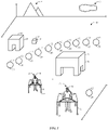
- FIG. 1 illustrates an embodiment of an attraction 10 (e.g., a virtual reality/alternate reality (VR/AR) thrill game) in accordance with the present disclosure.
- the attraction 10 may include a variety of interactive objects 12 placed about an environment 14 of the attraction 10. For example, one or more structures 16, items 18, and refill stations 20 may be placed about the environment 14.
- the attraction 10 may also include a variety of background images 21 in accordance with a theme of the attraction 10.
- the interactive objects 12 are simple constructions having flat, uniform surfaces.
- the interactive objects may comply with a theme of the environment.
- the structures 16 may be dinosaur models
- the items 18 may be dinosaur eggs
- the refill stations 20 may be bodies of water.
- the interactive objects may be endlessly customizable in location, size, shape, etc.
- the interactive objects 12 may be mechanically driven to move according to a theme.
- a structure 16 e.g., dinosaur model
- the interactive objects 12 may be coupled (e.g., bolted) to a surface of the environment 14. Additionally, or in the alternative, the interactive objects 12 may be manipulated (e.g., picked up, utilized, etc.) by users of the attraction 10.
- Users 22 of the attraction 10 may navigate the environment 14 while positioned within pods 24 (e.g., user-assisted vehicles, mobile pods). As will be discussed thoroughly below, the users 22 may walk around the environment 14 within the confines (e.g., boundary) of the pods 24. The users 22 may navigate the environment 14 with the purpose of completing a goal, or game objective. The goal, or game objective, may be communicated to the user through images displayed through VR/AR headgear 26 and/or, in certain embodiments, via a display screen associated with each pod 24. The users 22 may see VR/AR images in accordance with the theme of the environment through the VR/AR headgear 26. An embodiment of a VR/AR scenario as seen by the users 22 through the VR/AR headgear 26 may be seen in FIG. 2 .
- pods 24 e.g., user-assisted vehicles, mobile pods.
- FIG. 2 is an illustration of an embodiment of a VR/AR scenario 30 of the environment 14 of FIG. 1 .
- images of the VR/AR scenario 30 may be communicated to the user through the VR/AR headgear 26.
- the VR/AR scenario 30 may include many VR and/or AR visuals, as well as real-world images (e.g., images of the environment 14).
- the VR/AR scenario 30 may include VR/AR components 80 such as VR/AR creatures 32, VR/AR background features 34, VR/AR objects 36, VR/AR nature effects 38, VR/AR pods 40, distant VR/AR objects 39, etc.
- the VR/AR components 80 may appear in place of physical objects, e.g., interactive objects 12, of the environment 14.
- the users 22 may see the VR/AR creatures 32.
- users 22 may see VR/AR nature effects 38 and VR/AR objects 36, respectively.
- the pods 24 may appear as VR/AR pods 40.
- the VR/AR pods 40 may be portrayed to the users 22 in a way that is consistent with the theme of the environment discussed above.
- users 22 may appear to other users 22 as a creature in accordance with the theme of the environment.
- the VR/AR pod 40 images may be triggered if the users 22 are within a threshold distance of one another.
- a physical real-world pod 24 may be viewed as a robotic structure, a vehicle, etc.
- VR/AR creatures 32 corresponding to real-world objects may interact with the VR/AR creature 32 to some degree. For example, if the user 22, while positioned with the VR/AR pod 40, bumps into/approaches the VR/AR creatures 32, the user 22 may experience a reaction force from the collision because the pod 24 is actually contacting a physical object (e.g. structure 16). Depending on the context of the attraction narrative, such a collision may enhance the immersion effect. For example, in a bumper car narrative, a real-world bump may reflect a game goal. Further, real-world physical encounters may be augmented not only via VR/AR images as viewed by the user, but also by effects mediated through each pod 24, as provided herein.
- the user 22 may not come in contact with the physical object and still experience a reaction in accordance with the attraction narrative.
- the pod 24 may utilize a braking system and/or a locking/manipulation of wheels 41 of the pod 24.
- brakes of the braking system may engage (e.g., via locking of the wheels 41) and/or the wheels 41 may redirect the user 22 to avoid a collision with the physical object.
- engaging the brakes and/or manipulating the wheels 41 may enhance the immersion effect.
- Interaction with the VR/AR creatures 32 may cause an event (e.g., a special effect) to take place such as the VR/AR creature 32 roaring, stomping the ground, or turning to look at the user 22.
- an event e.g., a special effect
- the user 22 may literally walk across a refill station 20 and get wet from doing so.
- a further advantage of visuals of the VR/AR scenario 30 corresponding to real-world items is that the users may manipulate VR/AR objects 36. For example, a user may pick up a VR/AR object 36 (e.g., the item 18) via control of the pods 24.
- the user 22 may see that they are picking up an egg, a baby dinosaur, etc. In some embodiments, if the users 22 bump into the VR/AR objects 36, the users may see that they are knocking over the egg, baby dinosaur, etc.
- not every visual of the VR/AR scenario 30 may correspond to the interactive objects 12 of the environment 14.
- the user 22 may see VR/AR images of the background features 34 or other distant VR/AR objects 39.
- the distant VR/AR objects 39 may appear in a sky and out of reach, there may not be a benefit to having the distant VR/AR objects 39 corresponding to real-world objects of the environment 14.
- the background features 34 may correspond to a boundary (e.g., wall) of the environment 14.
- the pod 24 may provide a support and frame. It should be noted, as discussed below, that the pods 24 may provide methods of further interaction between the users 22 and the environment 14 and/or VR/AR scenario 30 in ways other than bumping into and walking over elements of the environment 14.
- FIG. 3 is a block diagram of a virtual reality attraction system 50 of the attraction 10 of FIG. 1 .
- Each of the users 22 may be provided with a pod 24 (e.g., user-assisted vehicle) that may be separate from or coupled to the VR/AR headgear 26.
- the VR/AR headgear 26 may be included as part of a helmet, a visor, a headband, a pair of blinders, one or more eyepatches, and/or other headwear or eyewear that may be worn by the users 22.
- the VR/AR headgear 26 may be communicatively coupled to a vehicle controller 52 of the pod 24, which is communicatively coupled to an attraction controller 56 of a master controller 58 and the environment 14 via a wireless network (e.g., wireless local area networks [WLAN], wireless wide area networks [WWAN], near field communication [NFC]).
- the vehicle controller 52, headgear 26, and attraction controller 56 may be used to create the VR/AR scenario 30, which may include an AR experience, a VR experience, a mixed reality (e.g., a combination of AR and VR) experience, a computer-mediated reality experience, a combination thereof, or other similar surreal environment for the users 22 as the users 22 enjoy the attraction 10.
- a wireless network e.g., wireless local area networks [WLAN], wireless wide area networks [WWAN], near field communication [NFC]
- the vehicle controller 52, headgear 26, and attraction controller 56 may be used to create the VR/AR scenario 30, which may include an AR experience, a VR experience, a mixed reality (e.g.
- the VR/AR headgear 26 may be worn by the users 22 throughout the duration of the game, such that users 22 may feel completely encompassed by the VR/AR scenario 30 and may perceive the VR/AR scenario 30 to be a real-world physical environment.
- the VR/AR scenario 30 may be a real-time video including real-world images of the environment 14 that the users 22 would see, even when not wearing the VR/AR headgear 26 electronically merged with one or more AR or VR images (e.g., virtual augmentations).
- the term "real-time" indicates that the images are obtained and/or provided in a timeframe substantially close to the time of actual observation.
- the VR/AR headgear 26 may be any of various wearable electronic devices that may be useful in creating an AR experience, a VR experience, and/or other computer-mediated experience to enhance the thrill factor of the attraction 10, and, by extension, the experience of the users 22 while in the attraction 10. It should be appreciated that VR/AR headgear 26 as discussed herein may be distinct from, and may provide many advantages over traditional devices such as traditional head-mounted displays (HMDs) and/or heads-up displays (HUDs).
- HMDs head-mounted displays
- HUDs heads-up displays
- the VR/AR headgear 26 may include a number of orientation and position sensors 57, e.g., accelerometers, magnetometers, gyroscopes, Global Positioning System (GPS) receivers, that may be used to track the position, orientation, and motion of the users 22 during a cycle of the attraction 10.
- orientation and position sensors 57 e.g., accelerometers, magnetometers, gyroscopes, Global Positioning System (GPS) receivers, that may be used to track the position, orientation, and motion of the users 22 during a cycle of the attraction 10.
- GPS Global Positioning System
- the VR/AR headgear 26 may be monitored by a monitoring system (e.g., one or more cameras 55) to determine position, location, orientation, and so forth of the VR/AR headgear 26 and that of the user 22.
- the monitoring system may be communicatively coupled to the virtual reality attraction system 50 and used to identify position, location, orientation, and so forth of the users 22.
- the pod 24 may also include one or more sensors 59 (e.g., weight sensors, mass sensors, motion sensors, ultrasonic sensors, position sensors) that may be useful in monitoring the respective users 22 for the virtual reality attraction system 50 to determine the point of view and/or location of the respective users 22.
- the environment 14 may also include one or more sensors 61 (e.g., weight sensors, mass sensors, motion sensors, ultrasonic sensors, cameras) that may be useful in monitoring the respective users 22 for the virtual reality attraction system 50 to determine the point of view and/or location of the respective users 22.
- sensors 61 e.g., weight sensors, mass sensors, motion sensors, ultrasonic sensors, cameras
- the vehicle controller 52 of the pod 24 may include processing circuitry, such as a processor 62 and a memory 64.
- the attraction controller 56 of the master controller 58 may include processing circuitry, such as a processor 66 and a memory 68.
- the processors 62, 66 may be operatively coupled to the memories 64, 68, respectively, to execute instructions for carrying out the presently disclosed techniques of generating the VR/AR scenario 30 to enhance the thrill factor of the attraction 10, and, by extension, the experience of the users 22 while in the attraction 10.
- These instructions may be encoded in programs or code stored in a tangible non-transitory computer-readable medium, such as the memories 64, 68 and/or other storage.
- the processors 62, 66 may be general-purpose processors, system- on-chip (SoC) devices, application-specific integrated circuits (ASICs), or some other similar processor configuration.
- the VR/AR headgear 26 may also include a pair of displays 70 respectively corresponding to each eye of the users 22.
- a unified display 70 may be employed.
- the display 70 may include an opaque liquid crystal display (LCD), an opaque organic light emitting diode (OLED) display, or other similar display useful in displaying real-time images of the environment 14 and the VR/AR scenario 30 to the users 22.
- the display 70 includes a see-through LCD or a see-through OLED display useful in allowing, for example, the users 22 to view the real-time images of the environment 14 and the VR/AR scenario 30 appearing on the display 70 while preserving the ability to see through display 70 to the actual and physical real-world environment (e.g., the environment 14).
- Camera(s) 72 may respectively correspond to the respective points of view of the users 22 and may be used to capture real-time video data (e.g., live video) of the environment 14.
- the camera(s) 70 of the VR/AR headgear 26 may be used to capture real-time images of the real-world physical environment 14 perceived by the respective users 22 from the point of view of the respective users 22.
- the VR/AR headgear 26 may then transmit (e.g. wirelessly via one or more communications interfaces included in the VR/AR headgear 26) real-time video data captured via the camera(s) 70 to the vehicle controller 52 and/or the attraction controller 56 for processing (e.g., via a graphics processing unit (GPU) of the controllers 52 and 56).
- GPU graphics processing unit
- the VR/AR headgear 26 may also transmit orientation data, position data, point of view data (e.g., focal length, orientation, pose, and so forth), motion tracking data, and so forth obtained and/or derived based on data obtained via orientation and position sensors 57, 59, 61, 55 (e.g., accelerometers, magnetometers, gyroscopes, Global Positioning System [GPS] receivers, motion-capture cameras and so forth) motion tracking sensors (e.g., electromagnetic and solid-state motion tracking sensors), and so forth, that may be included in the VR/AR headgear 26, the pod 24 , and the environment 14.
- orientation and position sensors 57, 59, 61, 55 e.g., accelerometers, magnetometers, gyroscopes, Global Positioning System [GPS] receivers, motion-capture cameras and so forth
- motion tracking sensors e.g., electromagnetic and solid-state motion tracking sensors
- the vehicle and/or attraction controllers 52, 56 may process the real-time video data (e.g., live video) and orientation and position data and/or point of view data received from the pod 24. Specifically, the vehicle and/or attraction controllers 52, 56 may use this data to generate a frame of reference to register the real-time video data with the generated VR/AR scenario 30. Specifically, using the frame of reference generated based on the orientation data, position data, point of view data, motion tracking data, and so forth, the vehicle and/or attraction controllers 52, 56 may then render a view of the VR/AR scenario 30 that is temporally and spatially commensurate with what the respective users 22 would perceive if not wearing the VR/AR headgear 26. The vehicle and/or attraction controllers 52, 56 may constantly update (e.g., in real-time) the rendering of the real-world images to reflect change in respective orientation, position, and/or motion of the respective users 22.
- the vehicle and/or attraction controllers 52, 56 may constantly update (e.g., in real-
- the vehicle and/or attraction controllers 52, 56 may render images (e.g., VR/AR scenario 30) at a real-time rate greater than or equal to approximately 20 frames per second (FPS), greater than or equal to approximately 30 FPS, greater than or equal to approximately 40 FPS, greater than or equal to approximately 50 FPS, greater than or equal to approximately 60 FPS, greater than or equal to approximately 90 FPS, or greater than or equal to approximately 120 FPS.
- the vehicle and/or attraction controllers 52, 56 may generate the real-world images of the environment 14 for each of the respective VR/AR headgear 26 worn by the respective users 22 (e.g., adjusted for the respective orientation, position, and point of view of the respective users 22).
- the vehicle and/or attraction controllers 52, 56 may also generate and render one or more VR/AR graphical images of the VR/AR scenario 30 superimposed on the real-world images of the environment 14 to create a complete AR experience, VR experience, mixed reality, and/or other computer- mediated experience for the users 22.
- the vehicle and/or attraction controllers 52, 56 may utilize one or more of the discussed video merging and/or optical merging techniques to superimpose the VR/AR graphical images of the VR/AR scenario 30 onto the real-world images of the environment 14, such that the users 22 perceive the real-world physical environment 14 of the attraction 10 (e.g., provided as rendered video data via the display 70) along with an VR/AR graphical image of the VR/AR scenario 30 (e.g., virtual augmentations) as the pods 24 traverse the attraction 10.
- the discussed video merging and/or optical merging techniques to superimpose the VR/AR graphical images of the VR/AR scenario 30 onto the real-world images of the environment 14, such that the users 22 perceive the real-world physical environment 14 of the attraction 10 (e.g., provided as rendered video data via the display 70) along with an VR/AR graphical image of the VR/AR scenario 30 (e.g., virtual augmentations) as the pods 24 traverse the attraction 10.
- the vehicle and/or attraction controllers 52, 56 may render a view of the VR/AR graphical images of the VR/AR scenario 30 that is temporally and spatially commensurate with the real-world images of the environment 14, such that the real-world images of the environment 14 may appear as a background overlaid with the VR/AR graphical images of the VR/AR scenario 30.
- a model may provide computer generated images for any available viewpoint and specific images may be provided to the VR/AR headgear 26 for display based on a detected orientation of the VR/AR headgear 26.
- the vehicle and/or attraction controllers 52, 56 may also generate one or more brightness, lighting, or shading models, and/or other photorealistic rendering models to generate the real-world images of the environment 14 and the VR/AR graphical images of the VR/AR scenario 30 adjusted to accurately reflect contrast and brightness of the real-world physical environment 14 (e.g., sunny day, partly cloudy day, cloudy day, evening, night) in rendering the real-world images of the environment 14 and the VR/AR graphical images of the VR/AR scenario 30.
- the real-world physical environment 14 e.g., sunny day, partly cloudy day, cloudy day, evening, night
- the vehicle and/or attraction controllers 52, 56 may, in some embodiments, receive weather related data from one or more weather forecast and/or prediction systems (e.g., Global Forecast System, Doppler radars, and so forth). The vehicle and/or attraction controllers 52, 56 may then use the weather-related data or other similar data to adjust the contrast, brightness, and/or other lighting effects of the real-world images of the environment and/or the VR/AR graphical images of the VR/AR scenario 30.
- weather forecast and/or prediction systems e.g., Global Forecast System, Doppler radars, and so forth.
- the vehicle and/or attraction controllers 52, 56 may then use the weather-related data or other similar data to adjust the contrast, brightness, and/or other lighting effects of the real-world images of the environment and/or the VR/AR graphical images of the VR/AR scenario 30.
- the vehicle and/or attraction controllers 52, 56 may adjust the contrast, brightness, and/or other lighting effects of the real-world images of the environment 14 and/or the VR/AR graphical images of the VR/AR scenario 30 based on lighting detected from one or more light sensors included in the VR/AR headgear 26 and/or pod 24 or based on the real-time video data captured by cameras 72. Furthermore, as previously noted, the vehicle and/or attraction controllers 52, 56 may constantly update (e.g., in real-time) the rendering of the VR/AR graphical images of the VR/AR scenario 30 to reflect change in respective orientations, positions, points of view, and/or motion of the respective users 22.
- the vehicle and/or attraction controllers 52, 56 may render the VR/AR graphical images of the VR/AR scenario on the display(s) 70 of each of the respective headgears 26 worn by the respective the users 22 adjusted for the variable respective positions, points of view, and motions of the respective the users 22.
- the vehicle and/or attraction controllers 52, 56 may also generate the VR/AR graphical images of the VR/AR scenario 30 at a time in which the users 22 cross a predetermined point within the environment 14.
- the vehicle and/or attraction controllers 52, 56 may use the received position data, point of view data, motion data along with GPS data or geographical informational systems (GIS) data to derive an illumination map of, for example, the attraction 10.
- GIS geographical informational systems
- the vehicle and/or attraction controllers 52, 56 may then use the map to introduce certain VR/AR graphical images of the VR/AR scenario 30 at certain predetermined points (e.g., points based on location, distance, or time) as the users 22 traverse the environment 14.
- predetermined points e.g., points based on location, distance, or time
- the video or image data captured via the camera(s) 72 may be used by the vehicle and/or attraction controllers 52, 56 to determine the points of location of the users 22 and when to introduce certain VR/AR graphical images of the VR/AR scenario 30.
- the GPU of the controllers 52 and 56 may perform one or more geometric recognition algorithms (e.g., shape or object recognition) or photometric recognition algorithms (e.g., face recognition or specific object recognition) to determine the position or location of the users 22 as well as the viewing position of the users 22.
- the vehicle controller 52 may be located within a carrying device (e.g., backpack) that may be worn by the user 22.
- the vehicle controller 52 and/or attraction controller 56 may communicate wirelessly with the VR/AR headgear 26. Further, in some embodiments, the vehicle controller 52 may be integrally coupled with the VR/AR headgear 26. In addition, it should also be noted that, while embodiments discussed above may utilize a separate a vehicle controller 52 and/or an attraction controller 56, some embodiments may utilize a single controller configured to perform the actions of the vehicle controller 52 and attraction controller 56 as described herein. In some embodiments, the single controller may be disposed on the pod 24 or somewhere else within the attraction 10.
- the pod 24 may include a display module 74, a special effects system 76 (e.g. special effects delivery system), a harness 77 (e.g., a user support), and a braking system 90.
- the display module 74 may be located in front of the user on a frame 81 of the pod 24. They display module 74 may communicate a variety of information to the user. For example, in some embodiments, display module 74 may communicate a map illustrating an overview (e.g., satellite view) of the VR/AR scenario 30.
- the map may display one or more icons representing the location of various components 80 (e.g., other users 22, VR/AR nature effects 38, VR/AR creatures 32, VR/AR objects 36, etc.) of the VR/AR scenario 30 as seen in FIG. 2 .
- the display module 74 may also communicate various messages to the users 22. For example, the display module may display an objective of the attraction 10, a message indicating that the user is approaching a specific location (e.g., a game boundary, a component 80, etc.), a message indicating a status of an objective of the attraction 10 (e.g., points, time remaining, possession of game objects, etc.).
- the display module 74 may function as an input/output device for the user.
- the display module 74 may include one or more input devices (e.g., one or more touchscreens, knobs, dials, buttons, switches, etc.) that the user may utilize to perform various functions (e.g., interactions, movements, etc.) within the attraction 10. In some embodiments, however, the display module 74 may only be utilized if the user 22 is not wearing the VR/AR headgear 26. In such embodiments, the display module 74 may communicate to the user 22 instructions for donning and/or storing the VR/AR headgear 26.
- input devices e.g., one or more touchscreens, knobs, dials, buttons, switches, etc.
- the special effects system 76 may include a fluid effects system 78, a vibration effects system 79, a sound effects system 82, an air effects system 84, or any combination thereof.
- a similar special effects system 76 may also be included within various aspects (e.g., components 80) of the environment 14.
- the fluid effects system 78 may include a bladder 86 (e.g., a reservoir) that may contain fluid (e.g., special effects material, water, scent fluids, etc.).
- the special effects system 76 may be utilized through one or more components 80 of the environment 14.
- the bladder 86 may be sealed and disposed within the frame 81 of the pod 24. Therefore, the bladder 86 may not be accessible to the user 22.
- the bladder 86 may be disposed on an exterior of the frame 81.
- the fluid effects system 78 may draw a fluid (e.g., water) from the bladder 86 to utilize in providing a special effect to the user.
- the fluid effects system 78 may emit a mist. The mist may be triggered when the users 22 navigate close to a component 80 (e.g., VR/AR nature effects 38, VR/AR creatures 32).
- the utilization of the fluid effects system 78 may provide for a unique experience to the user.
- the user 22 may feel as if they are literally feeling breath or spit flying from a dinosaur's mouth (e.g., a mouth of a VR creature 32), feeling spray from the VR/AR nature effects 38 (e.g., a spray/splash from the river 42 and/or puddle 44), and among other suitable fluid effects.
- the user may refill the bladder 86 by drawing water from one or more refill stations 20.
- the refill stations 20 may correspond to VR/AR water images in the VR/AR scenario 30 (e.g., puddle 44 and river 42). As such, the user 22 may navigate to one or more of the puddle 44 and/or river 42 to refill the bladder 86.
- the bladder 86 may be coupled to a pump, tube, and any other components necessary for drawing water from a source.
- the display module 74 may communicate to the user 22 that they are low on supplies (e.g., water), and direct the user 22 to refill from the one or more refill stations 20 (e.g., the puddle 44 and/or river 42 in the VR/AR scenario 30.).
- the user 22 may also navigate to the refill stations 20 to refill one or more VR/AR aspects (e.g., ammunition, air, fuel, etc.) in accordance with a theme of the attraction 10.
- the vibration, sound, and air effect systems 79, 82, 84 may provide a unique experience to the user in a similar fashion to the fluid effects system 78.
- the vibration effect system 79, the sound effect system 82, the air effect system 84, or any combination thereof may activate. If the user 22 approaches a VR creature 32, the user 22 may fully experience a dinosaur roar.
- the user 22 may hear the dinosaur roar through speakers of the sound effect system 82, feel a vibration fromthe dinosaur roar through the vibration effect system 79 and/or through a subwoofer of the sound effect system 82, feel a wind gust from the breath of the dinosaur through fans of the air effects system 84, smell the breath of the dinosaur through a smell additive of the air effects system 84, or any combination thereof.
- the special effects system 76 is applicable in many ways, and can be applied to fully immerse a user within any entertainment theme (e.g., wizarding, mummies, underwater adventures, superheroes, pirates, etc.).
- the braking system 90 of the vehicle may also be utilized in various ways to enhance the experience of the users 22 within the attraction 10.
- the controllers 52, 56 may process information regarding a location of the users 22 over time. Indeed, one or both of the controllers 52, 56 may calculate current locations of the users 22 as well as future locations of the users 22 based on a velocity (e.g., speed and direction) of the users 22.
- the controllers 52, 56 may calculate the locations/velocity utilizing information provided by the sensors 59, 61, 57 disposed within the environment 14 and/or on the pod 24. In some embodiments, the controllers 52, 56 may calculate the locations/velocity utilizing information provided by motion-capture cameras disposed within the environment 14 and/or on the pod 24.
- the controllers 52, 56 may selectively engage brakes 91 of the braking system 90 (e.g., via a drive signal) based at least on the locations of the users. Additionally, or in the alternative, the controller 52, 56 may manipulate the wheels 41 (e.g., via the drive signal) based at least on the locations of the users. For example, in some embodiments the brakes 91 may be engaged to some degree to slow the movement of the users 22 if the users 22 are heading towards a game boundary or object. The degree of engagement may depend on the velocity of the users 22. For example, the brakes 91 may be engaged to hinder movement if the user 22 is swiftly moving towards an object.
- the brakes 91 may be engaged to slow movement of the user 22 so that the user 22 does not exceed a predetermined speed. Therefore, all users 22 may not exceed the predetermined speed. In some embodiments, the brakes 91 may be engaged to retard the movement of the user 22 if the user 22 is moving towards an undesirable location (e.g., near a boundary, away from an objective, VR/AR mud, etc.). Particularly, in some embodiments, the brakes 91 may be engaged based on behavior of the user 22. For example, the brakes 91 may be engaged if the user 22 is moving inappropriately, quickly, erratically, etc. The calculated locations of the user(s) 22 relative to one another and environmental objects may be determined to be below a proximity threshold to one another.
- a collision or proximity signal may be generated by the controller 52, 56. If the proximity signal is generated by the attraction controller 56, the proximity signal may be provided to the vehicle controller 52 to cause engagement of the braking system 90. In addition, or in the alternative, the proximity signal may be provided to the vehicle controller 52 to manipulate (e.g., steer) the wheels 41.
- movement of the pod 24 may be at least partially (or completely) powered by a user (e.g., users 22).
- movement of the pod 24 may be at least partially powered by a motor 92.
- the motor 92 may provide enough power to overcome resistive forces from the pod 24.
- the pod 24 may be associated with some resistive forces (e.g., moment of inertia, friction, etc.). As such, the motor 92 may provide enough power to overcome the resistive forces so that the user 22 may not feel the effect of the resistive forces of the pod 24.
- the amount of power delivered from the motor 92 may be adjusted based on a weight of the user 22. In some embodiments, the amount of power that the motor 92 provides may be adjusted based on the physical capability of the user 22. For example, the motor 92 may provide more power to move the pod 24 if the user 22 is less physically capable. Overall, the motor 92 may provide individualized amounts of power to each pod 24 based on the user's abilities. Therefore, each user 22 may move with the same speed so that more physically capable users 22 do not have an advantage (e.g., speed advantage) over less physically capable users 22. As discussed above, the speed of the user 22 may also be regulated in part by use of the braking system 90. Furthermore, the pod 24 may be powered by any suitable power source 100, including, but not limited to, a battery, a solar panel, an electrical generator, a gas engine, or any combination thereof. In some embodiments, the power source 100 may be located within the vehicle controller 52.
- the master controller 58 may control some features of the attraction 10.
- the master controller 58 may include a distributed control system (DCS) or any computer-based workstation including an input/output interface 102 and a display 104, which in some embodiments, is fully or partially automated.
- Certain game information may be communicated through the display 104 of the master controller 58.
- statuses e.g., locations
- a video stream of the environment 14 may be shown on the display 104.
- an operator of the master controller 58 may regulate features (e.g., special effects system 76, components 80, etc.) of the attraction 10 from the input/output interface 102.
- an operator of the master controller 58 may take control of an individual pod 24. For example, once a game cycle has ended, the operator may control movement of all the pods so that all of the pods are moved to a starting location to begin the game cycle over again with new patrons. In some embodiments, the movement of all the pods 24 to a starting location for the start of a new game cycle may be automated.
- the pod 24 may include features to enhance the experience of a user 22 within the attraction 10.
- FIG. 4 is an illustration of an embodiment of one of the mobile pods 24 of FIG.
- the pod 24 may include the vehicle controller 52, the display module 74, the harness 77, and other features that may be used to enhance the experience of the user 22.
- the vehicle controller 52 and the display module 74 may be disposed on a front side of the frame 81. Therefore, the user 22 may easily access controls of the display module 74 (e.g., via a touchscreen, buttons, knobs, switches, separate input/output devices etc.).
- the user 22 may control aspects of the attraction 10 discussed above via one or more input devices 108.
- the input devices 108 may be joysticks, buttons, handles, totems, etc.
- the input devices 108 may be coupled to the frame 81.
- the input devices 108 may be removable from the frame 81 to some degree.
- the input devices 108 may be tethered to the frame 81 via a wire(e.g., a retractable wire).
- the input devices 108 may be picked up and waved around to provide a simulated interaction with the VR/AR scenario 30.
- the user 22 may utilize the input devices 108 to pick up an object (e.g., VR/AR object 36). Therefore, in some embodiments, the input devices 108 may appear as gripping devices (e.g., hands, clamps) to the user 22 within the VR/AR scenario 30.
- the input devices 108 may appear as a one or more of several different types of items (e.g., weapons, tools, etc.) in the VR/AR scenario 30.
- the pod 24 may be configured to form a boundary 110 about the user 22.
- the boundary may be circumferentially disposed 0 to 3 feet or 1 to 2 feet radially outward from the perimeter of the frame 81.
- the boundary 110 may be defined by the frame 81.
- the boundary 110 may define an area of space about the user 22 in which the user 22 may be isolated.
- the boundary 110 may be defined with a rigid translucent barrier (e.g., plastic) and/or one or more bumpers. Accordingly, the barrier may stop various objects (e.g., other users 22, structures 16, etc.) from coming inside the boundary via the bumpers.
- the bumpers may absorb impact forces when the pod 24 contacts various objects of the environment 14, thereby minimizing a force that the user 22 may experience as a result of contacting the various objects.
- the bumpers may be a wear item that may be easily replaceable.
- the attraction 10 may utilize various special effects systems.
- One or more of the special effects 76 may be provided from the pod 24.
- the pod 24 may be fitted with one or more fans for air effects 84, a bladder 86 for the fluid effects 78, one or more speakers for the sounds effect system 82, vibration device(s) of the vibration effects 79, etc.
- the user 22 may be secured within the harness.
- the harness 77 may be coupled to the frame 81.
- the frame 81 in conjunction with the harness 77, may provide support to the user 22.
- the design of the pod 24, in conjunction with the harness 77 and the frame 81 may prevent the pod 24, and the user 22 within the pod 24, from tipping over.
- the pod 24 may be designed such that stability may be maintained (e.g., passively and/or actively) regardless of sharp changes in speed/direction, contact with interactive objects 12 and/or another user 22, and so forth.
- the frame 81 and/or the harness 77 may be adjusted based on a height and/or weight of the user 22.
- Height of the frame 81 may be adjusted through length adjustment techniques (e.g., telescoping segments, hydraulic powered adjustment, compression/extension springs, linear actuators, etc.). Height of the frame 81 may be locked in place after the start of a cycle of attraction 10. Further, the harness 77 may be adjusted through one or more points of adjustment in accordance with the size and shape of the user 22. In some embodiments, the harness 77 may be coupled to the frame via one or more energy absorption systems (e.g., spring- damper systems, hydraulic systems, etc.). Overall, the harness 77 may allow the users 22 to move (e.g., walk) freely about the environment 14 while supporting the user 22 to prevent falling. The height of the frame 81 and harness 77 may be adjusted so that the harness 77 substantially supports the user 22 about a center of gravity of the user. In some embodiments, the harness 77 may support the users 22 from shoulders and/or waists of the respective users 22.
- energy absorption systems e.g., spring- damper systems, hydraulic systems, etc.
- FIG. 5 is block diagram of a refill station 20 within the environment 14 of FIG. 1 .
- water may be used in the special effects system 76 via the fluid effects.
- the bladder 86 e.g., reservoir
- the bladder 86 may be coupled to a pump, tube, and any other components necessary for drawing fluid from the refill station 20.
- the user 22 may position the pod 24 over one of the refill stations 20.
- the user 22 may position a leg of the frame 81 into the refill station 20 to draw fluid from the refill station 20 through tubing disposed on and/or within the frame 81.
- tubing disposed on/within the leg may provide for a system to draw fluid via an inlet of the frame 81.
- the pod 24 e.g., bladder 86
- the reservoir 150 may be disposed beneath a surface of the environment 14.
- each refill station 20 may draw fluid from a respective fluid reservoir 150.
- multiple refill stations 20 may draw water from a single fluid reservoir 150.
- FIG. 6 is a flow chart 160 of processing a position of one or more of the pods 24.
- position of the pods 24 may be determined at least in part via one or more sensors 59, 57, 61 disposed throughout the environment 14 and/or on the pods 24.
- the vehicle controller 52 and/or attraction controller 56 e.g., controllers 52, may receive information regarding a position of one or more of the pods 24 from the sensors 59, 57, 61.
- the position information may be transmitted to the controller 52, 56 via a wireless network, e.g., wireless local area networks (WLAN), wireless wide area networks (WWAN), near field communication (NFC).
- the controllers 52, 56 may analyze the location data and determine the location of one or more of the pods 24 and/or users 22.
- WLAN wireless local area networks
- WWAN wireless wide area networks
- NFC near field communication
- the controllers 52, 56 may update a VR/AR image based on the determined position of the pods 24. As discussed above, the controllers 52, 56 may provide certain VR/AR images to the users 22 (e.g., via the headgear 26) associated with certain locations of the environment. For example, the controllers 52, 56 may provide images of a component 80 reacting in some way if the user 22 is at a location near the component 80.
- the controllers 52, 56 may selectively activate brakes 91 and/or manipulate wheels 41 of one or more of the pods 24 based on the determined position of the pods 24.
- the brakes 91 and/or wheels 41 may be engaged to control a speed of the user 22, prevent a collision, to help direct the user 22 away from a boundary and/or towards a goal, or any combination thereof.
- the controllers 52, 56 may activate one or more special effects systems (e.g., special effects 78, 79, 82, 84, 86) based on the determined position of the pods 24. Specifically, as discussed above, the controllers 52, 56 may activate one or more special effect systems of the pod 24 and/or the environment 14 based on the location of the one or more users 22. For example, one or more special effects associated with a component 80 may be activated if the user is near the component 80.
- special effects systems e.g., special effects 78, 79, 82, 84, 86
Landscapes
- Engineering & Computer Science (AREA)
- Multimedia (AREA)
- Theoretical Computer Science (AREA)
- General Engineering & Computer Science (AREA)
- Physics & Mathematics (AREA)
- General Physics & Mathematics (AREA)
- Human Computer Interaction (AREA)
- Signal Processing (AREA)
- Computer Graphics (AREA)
- Computer Hardware Design (AREA)
- Optics & Photonics (AREA)
- Software Systems (AREA)
- User Interface Of Digital Computer (AREA)
- Processing Or Creating Images (AREA)
- Automation & Control Theory (AREA)
- Aviation & Aerospace Engineering (AREA)
- Radar, Positioning & Navigation (AREA)
- Remote Sensing (AREA)
- Steering Control In Accordance With Driving Conditions (AREA)
- Health & Medical Sciences (AREA)
- Life Sciences & Earth Sciences (AREA)
- Biophysics (AREA)
- Cardiology (AREA)
- General Health & Medical Sciences (AREA)
- Heart & Thoracic Surgery (AREA)
- Electromagnetism (AREA)
- Information Transfer Between Computers (AREA)
- Information Retrieval, Db Structures And Fs Structures Therefor (AREA)
Applications Claiming Priority (3)
| Application Number | Priority Date | Filing Date | Title |
|---|---|---|---|
| US15/591,975 US10656704B2 (en) | 2017-05-10 | 2017-05-10 | Virtual reality mobile pod |
| PCT/US2018/031344 WO2018208653A1 (en) | 2017-05-10 | 2018-05-07 | Virtual reality mobile pod |
| EP18729832.8A EP3621712B1 (en) | 2017-05-10 | 2018-05-07 | Virtual reality mobile pod |
Related Parent Applications (1)
| Application Number | Title | Priority Date | Filing Date |
|---|---|---|---|
| EP18729832.8A Division EP3621712B1 (en) | 2017-05-10 | 2018-05-07 | Virtual reality mobile pod |
Publications (2)
| Publication Number | Publication Date |
|---|---|
| EP3851176A1 EP3851176A1 (en) | 2021-07-21 |
| EP3851176B1 true EP3851176B1 (en) | 2022-12-14 |
Family
ID=62555169
Family Applications (2)
| Application Number | Title | Priority Date | Filing Date |
|---|---|---|---|
| EP21156123.8A Active EP3851176B1 (en) | 2017-05-10 | 2018-05-07 | Virtual reality mobile pod |
| EP18729832.8A Active EP3621712B1 (en) | 2017-05-10 | 2018-05-07 | Virtual reality mobile pod |
Family Applications After (1)
| Application Number | Title | Priority Date | Filing Date |
|---|---|---|---|
| EP18729832.8A Active EP3621712B1 (en) | 2017-05-10 | 2018-05-07 | Virtual reality mobile pod |
Country Status (10)
| Country | Link |
|---|---|
| US (1) | US10656704B2 (https=) |
| EP (2) | EP3851176B1 (https=) |
| JP (1) | JP7141412B2 (https=) |
| KR (1) | KR102588344B1 (https=) |
| CN (2) | CN119185963A (https=) |
| CA (1) | CA3061373A1 (https=) |
| ES (2) | ES2938078T3 (https=) |
| RU (1) | RU2756942C2 (https=) |
| SG (1) | SG11201910030SA (https=) |
| WO (1) | WO2018208653A1 (https=) |
Families Citing this family (20)
| Publication number | Priority date | Publication date | Assignee | Title |
|---|---|---|---|---|
| US9589000B2 (en) * | 2012-08-30 | 2017-03-07 | Atheer, Inc. | Method and apparatus for content association and history tracking in virtual and augmented reality |
| WO2019164514A1 (en) * | 2018-02-23 | 2019-08-29 | Google Llc | Transitioning between map view and augmented reality view |
| JP7235041B2 (ja) * | 2018-03-26 | 2023-03-08 | ソニーグループ株式会社 | 情報処理装置、情報処理方法、およびプログラム |
| US20190385372A1 (en) * | 2018-06-15 | 2019-12-19 | Microsoft Technology Licensing, Llc | Positioning a virtual reality passthrough region at a known distance |
| US10692294B1 (en) * | 2018-12-17 | 2020-06-23 | Universal City Studios Llc | Systems and methods for mediated augmented physical interaction |
| US10780359B2 (en) * | 2019-01-08 | 2020-09-22 | Universal City Studios Llc | Systems and methods for a connected augmented environment |
| JP6901541B2 (ja) * | 2019-11-28 | 2021-07-14 | 株式会社カプコン | ゲームプログラム、コンピュータ、及びゲームシステム |
| US11207606B2 (en) * | 2020-03-02 | 2021-12-28 | Universal City Studios Llc | Systems and methods for reactive projection-mapped show robot |
| US11774770B2 (en) * | 2020-06-03 | 2023-10-03 | Universal City Studios Llc | Interface device with three-dimensional (3-D) viewing functionality |
| CN111694430A (zh) * | 2020-06-10 | 2020-09-22 | 浙江商汤科技开发有限公司 | 一种ar场景画面呈现方法、装置、电子设备和存储介质 |
| DE102020128395A1 (de) * | 2020-10-28 | 2022-04-28 | Mack Rides Gmbh & Co Kg | Verfahren zum Betreiben eines Freizeitparks sowie Freizeitpark |
| CN113082728A (zh) * | 2021-04-14 | 2021-07-09 | 杭州易现先进科技有限公司 | 游乐车和增强现实交互系统 |
| US11684852B2 (en) * | 2021-05-04 | 2023-06-27 | Sony Interactive Entertainment Inc. | Create and remaster computer simulation skyboxes |
| JP7352598B2 (ja) * | 2021-07-01 | 2023-09-28 | 本田技研工業株式会社 | 仮想体験提供システム、及びプログラム |
| CN114428577A (zh) * | 2021-12-31 | 2022-05-03 | 合众新能源汽车有限公司 | 一种车载交互方法、车载交互终端及车载系统 |
| CA3249265A1 (en) * | 2022-01-20 | 2023-07-27 | Catalyst Entertainment Technology | Virtual Reality (VR) Enhanced Mobile Platform, Experience Venue for Such a Mobile Platform, and Experience Content and Interactivity Ecosystem |
| CN114625247A (zh) * | 2022-02-15 | 2022-06-14 | 广州小鹏汽车科技有限公司 | 基于虚拟现实的场景显示系统、方法及车辆 |
| CN116785694A (zh) * | 2022-03-16 | 2023-09-22 | 北京罗克维尔斯科技有限公司 | 区域确定方法及装置、电子设备和存储介质 |
| US20240189734A1 (en) * | 2022-12-13 | 2024-06-13 | Universal City Studios Llc | Reactive show action equipment system |
| JP2026069263A (ja) * | 2024-10-11 | 2026-04-23 | 本田技研工業株式会社 | 仮想体験提供システム、仮想体験提供方法、及びプログラム |
Family Cites Families (20)
| Publication number | Priority date | Publication date | Assignee | Title |
|---|---|---|---|---|
| US5152730A (en) * | 1991-06-04 | 1992-10-06 | Hoffman Roger E | Handless walking aid for preventing falls from loss of balance |
| US5669821A (en) * | 1994-04-12 | 1997-09-23 | Prather; James G. | Video augmented amusement rides |
| US5961541A (en) * | 1996-01-02 | 1999-10-05 | Ferrati; Benito | Orthopedic apparatus for walking and rehabilitating disabled persons including tetraplegic persons and for facilitating and stimulating the revival of comatose patients through the use of electronic and virtual reality units |
| JPH10309381A (ja) * | 1997-05-13 | 1998-11-24 | Yoshimasa Tanaka | 移動体用遊戯装置 |
| JP2000024062A (ja) * | 1998-07-08 | 2000-01-25 | Shigeo Tanahashi | 歩行訓練用自走車 |
| JP3363861B2 (ja) * | 2000-01-13 | 2003-01-08 | キヤノン株式会社 | 複合現実感提示装置及び複合現実感提示方法並びに記憶媒体 |
| JP2002126359A (ja) | 2000-10-26 | 2002-05-08 | Logistics Management Consulting Co Ltd | 遊技システム |
| US6866278B2 (en) * | 2003-04-11 | 2005-03-15 | Malcolm C. Gochioco | Small man-powered bump car |
| US20050183759A1 (en) * | 2003-09-02 | 2005-08-25 | Wolfe Mary L. | Walker with harness for an elderly, handicapped or convalescent person |
| TW200718457A (en) * | 2005-08-18 | 2007-05-16 | Aruze Corp | Gaming machine and terminal device included in gaming machine |
| CA2858543A1 (en) | 2013-08-12 | 2015-02-12 | GKart Inc. | Amusement vehicle, amusement environment for a vehicle and method of using the same |
| JP2015095197A (ja) | 2013-11-14 | 2015-05-18 | 泰章 岩井 | 情報処理システム、情報処理方法 |
| KR101669239B1 (ko) | 2014-05-23 | 2016-10-25 | 김신희 | 가상현실 시뮬레이터 |
| US9943759B2 (en) | 2014-06-16 | 2018-04-17 | Universal City Studios Llc | Interactive game floor system and method |
| ES2618333T3 (es) * | 2014-08-11 | 2017-06-21 | Vr Coaster Gmbh & Co. Kg | Procedimiento para hacer funcionar un dispositivo, en particular una atracción, un medio de transporte, un aparato de gimnasio o similar |
| US9690375B2 (en) | 2014-08-18 | 2017-06-27 | Universal City Studios Llc | Systems and methods for generating augmented and virtual reality images |
| US9905052B2 (en) | 2015-01-05 | 2018-02-27 | Worcester Polytechnic Institute | System and method for controlling immersiveness of head-worn displays |
| US20160349509A1 (en) | 2015-05-26 | 2016-12-01 | Microsoft Technology Licensing, Llc | Mixed-reality headset |
| JPWO2016189572A1 (ja) * | 2015-05-27 | 2018-03-08 | 泉陽興業株式会社 | 遊戯施設 |
| US11112266B2 (en) | 2016-02-12 | 2021-09-07 | Disney Enterprises, Inc. | Method for motion-synchronized AR or VR entertainment experience |
-
2017
- 2017-05-10 US US15/591,975 patent/US10656704B2/en active Active
-
2018
- 2018-05-07 WO PCT/US2018/031344 patent/WO2018208653A1/en not_active Ceased
- 2018-05-07 CN CN202411239453.XA patent/CN119185963A/zh active Pending
- 2018-05-07 ES ES21156123T patent/ES2938078T3/es active Active
- 2018-05-07 JP JP2019561903A patent/JP7141412B2/ja active Active
- 2018-05-07 SG SG11201910030S patent/SG11201910030SA/en unknown
- 2018-05-07 ES ES18729832T patent/ES2871875T3/es active Active
- 2018-05-07 CA CA3061373A patent/CA3061373A1/en active Pending
- 2018-05-07 RU RU2019140270A patent/RU2756942C2/ru active
- 2018-05-07 EP EP21156123.8A patent/EP3851176B1/en active Active
- 2018-05-07 EP EP18729832.8A patent/EP3621712B1/en active Active
- 2018-05-07 CN CN201880030595.1A patent/CN110582334A/zh active Pending
- 2018-05-07 KR KR1020197036317A patent/KR102588344B1/ko active Active
Also Published As
| Publication number | Publication date |
|---|---|
| JP2020519366A (ja) | 2020-07-02 |
| RU2756942C2 (ru) | 2021-10-07 |
| SG11201910030SA (en) | 2019-11-28 |
| EP3851176A1 (en) | 2021-07-21 |
| ES2871875T3 (es) | 2021-11-02 |
| EP3621712A1 (en) | 2020-03-18 |
| CN110582334A (zh) | 2019-12-17 |
| JP7141412B2 (ja) | 2022-09-22 |
| RU2019140270A (ru) | 2021-06-10 |
| US10656704B2 (en) | 2020-05-19 |
| ES2938078T3 (es) | 2023-04-04 |
| WO2018208653A1 (en) | 2018-11-15 |
| KR20200004875A (ko) | 2020-01-14 |
| US20180329480A1 (en) | 2018-11-15 |
| CN119185963A (zh) | 2024-12-27 |
| RU2019140270A3 (https=) | 2021-09-01 |
| KR102588344B1 (ko) | 2023-10-11 |
| CA3061373A1 (en) | 2018-11-15 |
| EP3621712B1 (en) | 2021-03-10 |
Similar Documents
| Publication | Publication Date | Title |
|---|---|---|
| EP3851176B1 (en) | Virtual reality mobile pod | |
| JP7754970B2 (ja) | 拡張現実及び仮想現実画像を生成するためのシステム及び方法 | |
| ES2965043T3 (es) | Sistema y método de paseo aumentado | |
| CN110869098B (zh) | 用于虚拟现实和增强现实路径管理的系统和方法 | |
| HK40120536A (zh) | 虚拟现实移动吊舱 | |
| HK40019793A (en) | Virtual reality mobile pod | |
| HK40025169A (en) | Systems and methods for virtual reality and augmented reality path management | |
| HK40025169B (en) | Systems and methods for virtual reality and augmented reality path management | |
| HK1242806A1 (en) | Systems and methods for generating augmented and virtual reality images |
Legal Events
| Date | Code | Title | Description |
|---|---|---|---|
| PUAI | Public reference made under article 153(3) epc to a published international application that has entered the european phase |
Free format text: ORIGINAL CODE: 0009012 |
|
| STAA | Information on the status of an ep patent application or granted ep patent |
Free format text: STATUS: THE APPLICATION HAS BEEN PUBLISHED |
|
| AC | Divisional application: reference to earlier application |
Ref document number: 3621712 Country of ref document: EP Kind code of ref document: P |
|
| AK | Designated contracting states |
Kind code of ref document: A1 Designated state(s): AL AT BE BG CH CY CZ DE DK EE ES FI FR GB GR HR HU IE IS IT LI LT LU LV MC MK MT NL NO PL PT RO RS SE SI SK SM TR |
|
| STAA | Information on the status of an ep patent application or granted ep patent |
Free format text: STATUS: REQUEST FOR EXAMINATION WAS MADE |
|
| 17P | Request for examination filed |
Effective date: 20220121 |
|
| RBV | Designated contracting states (corrected) |
Designated state(s): AL AT BE BG CH CY CZ DE DK EE ES FI FR GB GR HR HU IE IS IT LI LT LU LV MC MK MT NL NO PL PT RO RS SE SI SK SM TR |
|
| GRAP | Despatch of communication of intention to grant a patent |
Free format text: ORIGINAL CODE: EPIDOSNIGR1 |
|
| STAA | Information on the status of an ep patent application or granted ep patent |
Free format text: STATUS: GRANT OF PATENT IS INTENDED |
|
| INTG | Intention to grant announced |
Effective date: 20220624 |
|
| GRAS | Grant fee paid |
Free format text: ORIGINAL CODE: EPIDOSNIGR3 |
|
| GRAA | (expected) grant |
Free format text: ORIGINAL CODE: 0009210 |
|
| STAA | Information on the status of an ep patent application or granted ep patent |
Free format text: STATUS: THE PATENT HAS BEEN GRANTED |
|
| AC | Divisional application: reference to earlier application |
Ref document number: 3621712 Country of ref document: EP Kind code of ref document: P |
|
| AK | Designated contracting states |
Kind code of ref document: B1 Designated state(s): AL AT BE BG CH CY CZ DE DK EE ES FI FR GB GR HR HU IE IS IT LI LT LU LV MC MK MT NL NO PL PT RO RS SE SI SK SM TR |
|
| REG | Reference to a national code |
Ref country code: GB Ref legal event code: FG4D |
|
| REG | Reference to a national code |
Ref country code: CH Ref legal event code: EP |
|
| REG | Reference to a national code |
Ref country code: DE Ref legal event code: R096 Ref document number: 602018044387 Country of ref document: DE |
|
| REG | Reference to a national code |
Ref country code: IE Ref legal event code: FG4D |
|
| REG | Reference to a national code |
Ref country code: AT Ref legal event code: REF Ref document number: 1537340 Country of ref document: AT Kind code of ref document: T Effective date: 20230115 |
|
| REG | Reference to a national code |
Ref country code: ES Ref legal event code: FG2A Ref document number: 2938078 Country of ref document: ES Kind code of ref document: T3 Effective date: 20230404 |
|
| REG | Reference to a national code |
Ref country code: LT Ref legal event code: MG9D |
|
| REG | Reference to a national code |
Ref country code: NL Ref legal event code: MP Effective date: 20221214 |
|
| PG25 | Lapsed in a contracting state [announced via postgrant information from national office to epo] |
Ref country code: SE Free format text: LAPSE BECAUSE OF FAILURE TO SUBMIT A TRANSLATION OF THE DESCRIPTION OR TO PAY THE FEE WITHIN THE PRESCRIBED TIME-LIMIT Effective date: 20221214 Ref country code: NO Free format text: LAPSE BECAUSE OF FAILURE TO SUBMIT A TRANSLATION OF THE DESCRIPTION OR TO PAY THE FEE WITHIN THE PRESCRIBED TIME-LIMIT Effective date: 20230314 Ref country code: LT Free format text: LAPSE BECAUSE OF FAILURE TO SUBMIT A TRANSLATION OF THE DESCRIPTION OR TO PAY THE FEE WITHIN THE PRESCRIBED TIME-LIMIT Effective date: 20221214 Ref country code: FI Free format text: LAPSE BECAUSE OF FAILURE TO SUBMIT A TRANSLATION OF THE DESCRIPTION OR TO PAY THE FEE WITHIN THE PRESCRIBED TIME-LIMIT Effective date: 20221214 |
|
| PG25 | Lapsed in a contracting state [announced via postgrant information from national office to epo] |
Ref country code: RS Free format text: LAPSE BECAUSE OF FAILURE TO SUBMIT A TRANSLATION OF THE DESCRIPTION OR TO PAY THE FEE WITHIN THE PRESCRIBED TIME-LIMIT Effective date: 20221214 Ref country code: LV Free format text: LAPSE BECAUSE OF FAILURE TO SUBMIT A TRANSLATION OF THE DESCRIPTION OR TO PAY THE FEE WITHIN THE PRESCRIBED TIME-LIMIT Effective date: 20221214 Ref country code: HR Free format text: LAPSE BECAUSE OF FAILURE TO SUBMIT A TRANSLATION OF THE DESCRIPTION OR TO PAY THE FEE WITHIN THE PRESCRIBED TIME-LIMIT Effective date: 20221214 Ref country code: GR Free format text: LAPSE BECAUSE OF FAILURE TO SUBMIT A TRANSLATION OF THE DESCRIPTION OR TO PAY THE FEE WITHIN THE PRESCRIBED TIME-LIMIT Effective date: 20230315 |
|
| P01 | Opt-out of the competence of the unified patent court (upc) registered |
Effective date: 20230522 |
|
| PG25 | Lapsed in a contracting state [announced via postgrant information from national office to epo] |
Ref country code: NL Free format text: LAPSE BECAUSE OF FAILURE TO SUBMIT A TRANSLATION OF THE DESCRIPTION OR TO PAY THE FEE WITHIN THE PRESCRIBED TIME-LIMIT Effective date: 20221214 |
|
| PG25 | Lapsed in a contracting state [announced via postgrant information from national office to epo] |
Ref country code: SM Free format text: LAPSE BECAUSE OF FAILURE TO SUBMIT A TRANSLATION OF THE DESCRIPTION OR TO PAY THE FEE WITHIN THE PRESCRIBED TIME-LIMIT Effective date: 20221214 Ref country code: RO Free format text: LAPSE BECAUSE OF FAILURE TO SUBMIT A TRANSLATION OF THE DESCRIPTION OR TO PAY THE FEE WITHIN THE PRESCRIBED TIME-LIMIT Effective date: 20221214 Ref country code: PT Free format text: LAPSE BECAUSE OF FAILURE TO SUBMIT A TRANSLATION OF THE DESCRIPTION OR TO PAY THE FEE WITHIN THE PRESCRIBED TIME-LIMIT Effective date: 20230414 Ref country code: EE Free format text: LAPSE BECAUSE OF FAILURE TO SUBMIT A TRANSLATION OF THE DESCRIPTION OR TO PAY THE FEE WITHIN THE PRESCRIBED TIME-LIMIT Effective date: 20221214 Ref country code: CZ Free format text: LAPSE BECAUSE OF FAILURE TO SUBMIT A TRANSLATION OF THE DESCRIPTION OR TO PAY THE FEE WITHIN THE PRESCRIBED TIME-LIMIT Effective date: 20221214 |
|
| PG25 | Lapsed in a contracting state [announced via postgrant information from national office to epo] |
Ref country code: SK Free format text: LAPSE BECAUSE OF FAILURE TO SUBMIT A TRANSLATION OF THE DESCRIPTION OR TO PAY THE FEE WITHIN THE PRESCRIBED TIME-LIMIT Effective date: 20221214 Ref country code: PL Free format text: LAPSE BECAUSE OF FAILURE TO SUBMIT A TRANSLATION OF THE DESCRIPTION OR TO PAY THE FEE WITHIN THE PRESCRIBED TIME-LIMIT Effective date: 20221214 Ref country code: IS Free format text: LAPSE BECAUSE OF FAILURE TO SUBMIT A TRANSLATION OF THE DESCRIPTION OR TO PAY THE FEE WITHIN THE PRESCRIBED TIME-LIMIT Effective date: 20230414 Ref country code: AL Free format text: LAPSE BECAUSE OF FAILURE TO SUBMIT A TRANSLATION OF THE DESCRIPTION OR TO PAY THE FEE WITHIN THE PRESCRIBED TIME-LIMIT Effective date: 20221214 |
|
| REG | Reference to a national code |
Ref country code: DE Ref legal event code: R097 Ref document number: 602018044387 Country of ref document: DE |
|
| PLBE | No opposition filed within time limit |
Free format text: ORIGINAL CODE: 0009261 |
|
| STAA | Information on the status of an ep patent application or granted ep patent |
Free format text: STATUS: NO OPPOSITION FILED WITHIN TIME LIMIT |
|
| PG25 | Lapsed in a contracting state [announced via postgrant information from national office to epo] |
Ref country code: DK Free format text: LAPSE BECAUSE OF FAILURE TO SUBMIT A TRANSLATION OF THE DESCRIPTION OR TO PAY THE FEE WITHIN THE PRESCRIBED TIME-LIMIT Effective date: 20221214 |
|
| 26N | No opposition filed |
Effective date: 20230915 |
|
| PG25 | Lapsed in a contracting state [announced via postgrant information from national office to epo] |
Ref country code: SI Free format text: LAPSE BECAUSE OF FAILURE TO SUBMIT A TRANSLATION OF THE DESCRIPTION OR TO PAY THE FEE WITHIN THE PRESCRIBED TIME-LIMIT Effective date: 20221214 |
|
| REG | Reference to a national code |
Ref country code: AT Ref legal event code: UEP Ref document number: 1537340 Country of ref document: AT Kind code of ref document: T Effective date: 20221214 |
|
| PG25 | Lapsed in a contracting state [announced via postgrant information from national office to epo] |
Ref country code: MC Free format text: LAPSE BECAUSE OF FAILURE TO SUBMIT A TRANSLATION OF THE DESCRIPTION OR TO PAY THE FEE WITHIN THE PRESCRIBED TIME-LIMIT Effective date: 20221214 |
|
| REG | Reference to a national code |
Ref country code: BE Ref legal event code: MM Effective date: 20230531 |
|
| PG25 | Lapsed in a contracting state [announced via postgrant information from national office to epo] |
Ref country code: MC Free format text: LAPSE BECAUSE OF FAILURE TO SUBMIT A TRANSLATION OF THE DESCRIPTION OR TO PAY THE FEE WITHIN THE PRESCRIBED TIME-LIMIT Effective date: 20221214 Ref country code: LU Free format text: LAPSE BECAUSE OF NON-PAYMENT OF DUE FEES Effective date: 20230507 |
|
| REG | Reference to a national code |
Ref country code: IE Ref legal event code: MM4A |
|
| PG25 | Lapsed in a contracting state [announced via postgrant information from national office to epo] |
Ref country code: IE Free format text: LAPSE BECAUSE OF NON-PAYMENT OF DUE FEES Effective date: 20230507 |
|
| PG25 | Lapsed in a contracting state [announced via postgrant information from national office to epo] |
Ref country code: IE Free format text: LAPSE BECAUSE OF NON-PAYMENT OF DUE FEES Effective date: 20230507 |
|
| PG25 | Lapsed in a contracting state [announced via postgrant information from national office to epo] |
Ref country code: BE Free format text: LAPSE BECAUSE OF NON-PAYMENT OF DUE FEES Effective date: 20230531 |
|
| PG25 | Lapsed in a contracting state [announced via postgrant information from national office to epo] |
Ref country code: BG Free format text: LAPSE BECAUSE OF FAILURE TO SUBMIT A TRANSLATION OF THE DESCRIPTION OR TO PAY THE FEE WITHIN THE PRESCRIBED TIME-LIMIT Effective date: 20221214 |
|
| PG25 | Lapsed in a contracting state [announced via postgrant information from national office to epo] |
Ref country code: BG Free format text: LAPSE BECAUSE OF FAILURE TO SUBMIT A TRANSLATION OF THE DESCRIPTION OR TO PAY THE FEE WITHIN THE PRESCRIBED TIME-LIMIT Effective date: 20221214 |
|
| PGFP | Annual fee paid to national office [announced via postgrant information from national office to epo] |
Ref country code: DE Payment date: 20250529 Year of fee payment: 8 |
|
| PGFP | Annual fee paid to national office [announced via postgrant information from national office to epo] |
Ref country code: ES Payment date: 20250602 Year of fee payment: 8 |
|
| PGFP | Annual fee paid to national office [announced via postgrant information from national office to epo] |
Ref country code: IT Payment date: 20250521 Year of fee payment: 8 |
|
| PGFP | Annual fee paid to national office [announced via postgrant information from national office to epo] |
Ref country code: FR Payment date: 20250526 Year of fee payment: 8 |
|
| PGFP | Annual fee paid to national office [announced via postgrant information from national office to epo] |
Ref country code: CH Payment date: 20250601 Year of fee payment: 8 |
|
| PGFP | Annual fee paid to national office [announced via postgrant information from national office to epo] |
Ref country code: AT Payment date: 20250423 Year of fee payment: 8 |
|
| PG25 | Lapsed in a contracting state [announced via postgrant information from national office to epo] |
Ref country code: CY Free format text: LAPSE BECAUSE OF FAILURE TO SUBMIT A TRANSLATION OF THE DESCRIPTION OR TO PAY THE FEE WITHIN THE PRESCRIBED TIME-LIMIT; INVALID AB INITIO Effective date: 20180507 |
|
| PG25 | Lapsed in a contracting state [announced via postgrant information from national office to epo] |
Ref country code: HU Free format text: LAPSE BECAUSE OF FAILURE TO SUBMIT A TRANSLATION OF THE DESCRIPTION OR TO PAY THE FEE WITHIN THE PRESCRIBED TIME-LIMIT; INVALID AB INITIO Effective date: 20180507 |
|
| PG25 | Lapsed in a contracting state [announced via postgrant information from national office to epo] |
Ref country code: TR Free format text: LAPSE BECAUSE OF FAILURE TO SUBMIT A TRANSLATION OF THE DESCRIPTION OR TO PAY THE FEE WITHIN THE PRESCRIBED TIME-LIMIT Effective date: 20221214 |
|
| PGFP | Annual fee paid to national office [announced via postgrant information from national office to epo] |
Ref country code: GB Payment date: 20260327 Year of fee payment: 9 |