EP3851024B1 - Medical observation system, medical observation device and medical observation method - Google Patents
Medical observation system, medical observation device and medical observation method Download PDFInfo
- Publication number
- EP3851024B1 EP3851024B1 EP19860561.0A EP19860561A EP3851024B1 EP 3851024 B1 EP3851024 B1 EP 3851024B1 EP 19860561 A EP19860561 A EP 19860561A EP 3851024 B1 EP3851024 B1 EP 3851024B1
- Authority
- EP
- European Patent Office
- Prior art keywords
- surgical field
- region
- field image
- interest
- magnified
- Prior art date
- Legal status (The legal status is an assumption and is not a legal conclusion. Google has not performed a legal analysis and makes no representation as to the accuracy of the status listed.)
- Active
Links
Images


Classifications
-
- A—HUMAN NECESSITIES
- A61—MEDICAL OR VETERINARY SCIENCE; HYGIENE
- A61B—DIAGNOSIS; SURGERY; IDENTIFICATION
- A61B1/00—Instruments for performing medical examinations of the interior of cavities or tubes of the body by visual or photographical inspection, e.g. endoscopes; Illuminating arrangements therefor
- A61B1/00002—Operational features of endoscopes
- A61B1/00004—Operational features of endoscopes characterised by electronic signal processing
- A61B1/00009—Operational features of endoscopes characterised by electronic signal processing of image signals during a use of endoscope
- A61B1/000094—Operational features of endoscopes characterised by electronic signal processing of image signals during a use of endoscope extracting biological structures
-
- A—HUMAN NECESSITIES
- A61—MEDICAL OR VETERINARY SCIENCE; HYGIENE
- A61B—DIAGNOSIS; SURGERY; IDENTIFICATION
- A61B1/00—Instruments for performing medical examinations of the interior of cavities or tubes of the body by visual or photographical inspection, e.g. endoscopes; Illuminating arrangements therefor
- A61B1/00002—Operational features of endoscopes
- A61B1/00043—Operational features of endoscopes provided with output arrangements
- A61B1/00045—Display arrangement
- A61B1/00048—Constructional features of the display
-
- A—HUMAN NECESSITIES
- A61—MEDICAL OR VETERINARY SCIENCE; HYGIENE
- A61B—DIAGNOSIS; SURGERY; IDENTIFICATION
- A61B1/00—Instruments for performing medical examinations of the interior of cavities or tubes of the body by visual or photographical inspection, e.g. endoscopes; Illuminating arrangements therefor
- A61B1/00002—Operational features of endoscopes
- A61B1/00043—Operational features of endoscopes provided with output arrangements
- A61B1/00045—Display arrangement
- A61B1/0005—Display arrangement combining images e.g. side-by-side, superimposed or tiled
-
- A—HUMAN NECESSITIES
- A61—MEDICAL OR VETERINARY SCIENCE; HYGIENE
- A61B—DIAGNOSIS; SURGERY; IDENTIFICATION
- A61B1/00—Instruments for performing medical examinations of the interior of cavities or tubes of the body by visual or photographical inspection, e.g. endoscopes; Illuminating arrangements therefor
- A61B1/00163—Optical arrangements
- A61B1/00188—Optical arrangements with focusing or zooming features
-
- A—HUMAN NECESSITIES
- A61—MEDICAL OR VETERINARY SCIENCE; HYGIENE
- A61B—DIAGNOSIS; SURGERY; IDENTIFICATION
- A61B1/00—Instruments for performing medical examinations of the interior of cavities or tubes of the body by visual or photographical inspection, e.g. endoscopes; Illuminating arrangements therefor
- A61B1/00163—Optical arrangements
- A61B1/00194—Optical arrangements adapted for three-dimensional imaging
-
- A—HUMAN NECESSITIES
- A61—MEDICAL OR VETERINARY SCIENCE; HYGIENE
- A61B—DIAGNOSIS; SURGERY; IDENTIFICATION
- A61B90/00—Instruments, implements or accessories specially adapted for surgery or diagnosis and not covered by any of the groups A61B1/00 - A61B50/00, e.g. for luxation treatment or for protecting wound edges
- A61B90/20—Surgical microscopes characterised by non-optical aspects
- A61B90/25—Supports therefor
-
- A—HUMAN NECESSITIES
- A61—MEDICAL OR VETERINARY SCIENCE; HYGIENE
- A61B—DIAGNOSIS; SURGERY; IDENTIFICATION
- A61B90/00—Instruments, implements or accessories specially adapted for surgery or diagnosis and not covered by any of the groups A61B1/00 - A61B50/00, e.g. for luxation treatment or for protecting wound edges
- A61B90/36—Image-producing devices or illumination devices not otherwise provided for
- A61B90/361—Image-producing devices, e.g. surgical cameras
-
- G—PHYSICS
- G02—OPTICS
- G02B—OPTICAL ELEMENTS, SYSTEMS OR APPARATUS
- G02B21/00—Microscopes
- G02B21/0004—Microscopes specially adapted for specific applications
- G02B21/0012—Surgical microscopes
-
- G—PHYSICS
- G02—OPTICS
- G02B—OPTICAL ELEMENTS, SYSTEMS OR APPARATUS
- G02B21/00—Microscopes
- G02B21/36—Microscopes arranged for photographic purposes or projection purposes or digital imaging or video purposes including associated control and data processing arrangements
-
- G—PHYSICS
- G02—OPTICS
- G02B—OPTICAL ELEMENTS, SYSTEMS OR APPARATUS
- G02B23/00—Telescopes, e.g. binoculars; Periscopes; Instruments for viewing the inside of hollow bodies; Viewfinders; Optical aiming or sighting devices
- G02B23/24—Instruments or systems for viewing the inside of hollow bodies, e.g. fibrescopes
- G02B23/2407—Optical details
- G02B23/2423—Optical details of the distal end
-
- G—PHYSICS
- G02—OPTICS
- G02B—OPTICAL ELEMENTS, SYSTEMS OR APPARATUS
- G02B23/00—Telescopes, e.g. binoculars; Periscopes; Instruments for viewing the inside of hollow bodies; Viewfinders; Optical aiming or sighting devices
- G02B23/24—Instruments or systems for viewing the inside of hollow bodies, e.g. fibrescopes
- G02B23/2476—Non-optical details, e.g. housings, mountings, supports
- G02B23/2484—Arrangements in relation to a camera or imaging device
-
- G—PHYSICS
- G02—OPTICS
- G02B—OPTICAL ELEMENTS, SYSTEMS OR APPARATUS
- G02B27/00—Optical systems or apparatus not provided for by any of the groups G02B1/00 - G02B26/00, G02B30/00
- G02B27/64—Imaging systems using optical elements for stabilisation of the lateral and angular position of the image
- G02B27/646—Imaging systems using optical elements for stabilisation of the lateral and angular position of the image compensating for small deviations, e.g. due to vibration or shake
-
- A—HUMAN NECESSITIES
- A61—MEDICAL OR VETERINARY SCIENCE; HYGIENE
- A61B—DIAGNOSIS; SURGERY; IDENTIFICATION
- A61B1/00—Instruments for performing medical examinations of the interior of cavities or tubes of the body by visual or photographical inspection, e.g. endoscopes; Illuminating arrangements therefor
- A61B1/00002—Operational features of endoscopes
- A61B1/00004—Operational features of endoscopes characterised by electronic signal processing
- A61B1/00006—Operational features of endoscopes characterised by electronic signal processing of control signals
-
- A—HUMAN NECESSITIES
- A61—MEDICAL OR VETERINARY SCIENCE; HYGIENE
- A61B—DIAGNOSIS; SURGERY; IDENTIFICATION
- A61B17/00—Surgical instruments, devices or methods
- A61B2017/00017—Electrical control of surgical instruments
- A61B2017/00207—Electrical control of surgical instruments with hand gesture control or hand gesture recognition
-
- A—HUMAN NECESSITIES
- A61—MEDICAL OR VETERINARY SCIENCE; HYGIENE
- A61B—DIAGNOSIS; SURGERY; IDENTIFICATION
- A61B90/00—Instruments, implements or accessories specially adapted for surgery or diagnosis and not covered by any of the groups A61B1/00 - A61B50/00, e.g. for luxation treatment or for protecting wound edges
- A61B90/30—Devices for illuminating a surgical field, the devices having an interrelation with other surgical devices or with a surgical procedure
- A61B2090/309—Devices for illuminating a surgical field, the devices having an interrelation with other surgical devices or with a surgical procedure using white LEDs
-
- A—HUMAN NECESSITIES
- A61—MEDICAL OR VETERINARY SCIENCE; HYGIENE
- A61B—DIAGNOSIS; SURGERY; IDENTIFICATION
- A61B90/00—Instruments, implements or accessories specially adapted for surgery or diagnosis and not covered by any of the groups A61B1/00 - A61B50/00, e.g. for luxation treatment or for protecting wound edges
- A61B90/36—Image-producing devices or illumination devices not otherwise provided for
- A61B90/361—Image-producing devices, e.g. surgical cameras
- A61B2090/3616—Magnifying glass
-
- A—HUMAN NECESSITIES
- A61—MEDICAL OR VETERINARY SCIENCE; HYGIENE
- A61B—DIAGNOSIS; SURGERY; IDENTIFICATION
- A61B90/00—Instruments, implements or accessories specially adapted for surgery or diagnosis and not covered by any of the groups A61B1/00 - A61B50/00, e.g. for luxation treatment or for protecting wound edges
- A61B90/36—Image-producing devices or illumination devices not otherwise provided for
- A61B2090/364—Correlation of different images or relation of image positions in respect to the body
- A61B2090/367—Correlation of different images or relation of image positions in respect to the body creating a 3D dataset from 2D images using position information
-
- A—HUMAN NECESSITIES
- A61—MEDICAL OR VETERINARY SCIENCE; HYGIENE
- A61B—DIAGNOSIS; SURGERY; IDENTIFICATION
- A61B2560/00—Constructional details of operational features of apparatus; Accessories for medical measuring apparatus
- A61B2560/04—Constructional details of apparatus
- A61B2560/0437—Trolley or cart-type apparatus
-
- A—HUMAN NECESSITIES
- A61—MEDICAL OR VETERINARY SCIENCE; HYGIENE
- A61B—DIAGNOSIS; SURGERY; IDENTIFICATION
- A61B34/00—Computer-aided surgery; Manipulators or robots specially adapted for use in surgery
- A61B34/25—User interfaces for surgical systems
Definitions
- the present disclosure relates to a medical observation system, a medical observation apparatus, and a medical observation method.
- EP 3 151 720 A1 discloses a medical imaging apparatus including a controller including circuitry configured to control display on a display area of a medical image, control display on the display area of a superimposed image corresponding to the medical image, detect a position of an important element within the medical image, and determine a position of the superimposed image within the display area.
- Patent Literature 1 JP 2016-192986 A
- Patent Literature 1 uses a feature point and electronic zoom tracking is performed onto that position. Therefore, in a surgical operation, for example, in a case where an endoscope inserted into a body cavity is frequently moved in various directions for observation during the operation, an image captured by the endoscope involves a large movement, leading to insufficient tracking performance for the feature point. In addition, a treatment applied to the target tissue would change the appearance of that part, which causes a problem of making it difficult to track the feature point. This leads to a difficulty in achieving stable observation of the region to be magnified.
- the present disclosure proposes a medical observation system, a medical observation apparatus, and a medical observation method capable of magnifying and stably observing the affected part from a distant position.
- FIG. 1 is a view illustrating an example of a schematic configuration of an endoscopic surgery system 5000 to which a medical observation system according to the present disclosure is applicable.
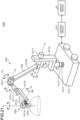
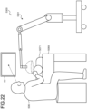
- FIG. 1 illustrates a scene in which a surgeon (doctor) 5061 is during surgery on a patient 5071 on a patient bed 5069 using the endoscopic surgery system 5000.
- An endoscope operator 5062 holds an endoscope 5001 and inserts the endoscope 5001 into the body cavity of the patient 5071.
- An assistant 5063 is holding a surgical tool 5017 and inserting the tool into the body cavity of the patient 5071.
- trocars 5025a to 5025d are punctured into an abdominal wall, instead of performing open surgery of cutting the abdominal wall.
- a lens barrel 5003 of the endoscope 5001 and other surgical tools 5017 are inserted into the body cavity of the patient 5071.
- an insufflation tube 5019, an energy treatment tool 5021 and forceps 5023 are being inserted into the body cavity of the patient 5071.
- the insufflation tube 5019 pumps gas into the body cavity of the patient 5071 to inflate the body cavity for the purpose of assuring the field of view for the endoscope 5001 and the work space for the surgeon 5061.
- the energy treatment tool 5021 is a treatment tool used for incision and detachment of tissues, blood vessel sealing, or the like, by using high-frequency current or ultrasonic vibration.
- the insufflation tube 5019 and the energy treatment tool 5021 are connected to a control device (not illustrated), and the surgical tool 5017 is used to perform predetermined operations, instructed by the surgeon 5061 or the like.
- the surgical tool 5017 illustrated in the figure is just an example, and other applicable examples of the surgical tool 5017 include various surgical tools generally used in endoscopic surgery, such as tweezers and a retractor.
- An image of the surgical field in the body cavity of the patient 5071 (hereinafter referred to as a surgical field image) captured by the endoscope 5001 is displayed on a display device 50.
- the surgeon 5061 While viewing the surgical field image displayed on the display device 50 in real time, the surgeon 5061 performs procedures such as resecting the affected part by using the energy treatment tool 5021 and the forceps 5023.
- the endoscope operator 5062 adjusts the position of the endoscope 5001 while viewing the surgical field image displayed on the display device 50 in real time so that the affected part is positioned within the surgical field image.
- the insufflation tube 5019, the energy treatment tool 5021, and the forceps 5023 are held by the surgeon 5061, the assistant 5063, or the like during the surgery.
- the endoscope 5001 includes: a lens barrel 5003 (also referred to as a scope), a region of a predetermined length from a distal end of which is inserted into the body cavity of the patient 5071; and a camera head 5005 connected to a proximal end of the lens barrel 5003.
- a lens barrel 5003 also referred to as a scope
- FIG. 1 illustrates the endoscope 5001 as a rigid scope having the lens barrel 5003 of a rigid type.
- the endoscope 5001 can be a flexible scope having the lens barrel 5003 of a flexible material.
- the distal end of the lens barrel 5003 has an aperture to which an objective lens is fitted.
- the endoscope 5001 is connected to a light source device (not illustrated).
- the light generated by the light source device is guided to the distal end of the lens barrel 5003 by a light guide extending inside the lens barrel 5003, and this guided light will be emitted toward an observation target in the body cavity of the patient 5071 through the objective lens.
- the endoscope 5001 may be a forward viewing endoscope, a forward-oblique viewing endoscope, or a side-viewing endoscope.
- An optical system and an imaging element are provided inside the camera head 5005.
- Reflected light (observation light) from the observation target is focused onto the imaging element by the optical system.
- the observation light is photoelectrically converted by the imaging element so as to generate an electric signal corresponding to the observation light, that is, an image signal corresponding to the observation image.
- the image signal is transmitted as RAW data to a camera control unit (CCU) 12a.
- the camera head 5005 has a function of adjusting a magnification and a focal length by appropriately driving the optical system.
- the camera head 5005 may include a plurality of imaging elements in order to support stereoscopic viewing (3D display) or the like.
- a plurality of relay optical systems is provided inside the lens barrel 5003 in order to guide the observation light to each of the plurality of imaging elements.
- the endoscopic surgery system 5000 includes an input device that receives various information inputs and instruction inputs from the user, namely, the surgeon 5061, the endoscope operator 5062, or the assistant 5063.
- the user inputs various types of information related to the surgery, such as physical information regarding the patient and information regarding the surgical procedure, via the input device.
- the user inputs, through the input device, an instruction to change imaging conditions (type of irradiation light, magnification, focal length, or the like) of the endoscope 5001, an instruction to drive the surgical tool 5017 such as the energy treatment tool 5021, for example.
- FIG. 1 illustrates an example in which an endoscope operator 5062 inputs information using a foot switch 5057, which is an example of the input device.
- the endoscope operator 5062 sets a region-of-interest in a surgical field image via the foot switch 5057. Details of this will be described below.
- the touch panel may be provided on a display surface of the display device 50.
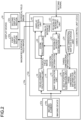
- FIG. 2 is a functional block diagram illustrating a functional configuration of a medical observation system 10a applicable to endoscopic surgery.
- the medical observation system 10a is a system applied to the endoscopic surgery system 5000 described above and configured to monitor a surgical field image by the endoscope 5001 inserted into the body cavity of the patient 5071 during surgery.
- the medical observation system 10a is a system that constantly displays a magnified surgical field image obtained by magnifying the set region-of-interest based on a three-dimensional position of the surgical field, regardless of the position and orientation of the endoscope 5001.
- the medical observation system 10a includes an imaging device 42a and a camera control unit 12a. Mounted on the camera head 5005 of the endoscope 5001 described above, the imaging device 42a images the surgical field in the body cavity of the patient 5071 to obtain a surgical field image. When the imaging device 42a captures an image, the camera control unit 12a generates a surgical field image as well as generating three-dimensional information regarding the surgical field.
- the imaging device 42a includes an imaging element 44a.
- the imaging element 44a is represented by an imaging element (photoelectric conversion element) such as a complementary metal oxide semiconductor (CMOS) image sensor or a charge coupled device (CCD) image sensor, and converts light from the surgical field into an electric signal.
- CMOS complementary metal oxide semiconductor
- CCD charge coupled device
- the camera control unit 12a includes a three-dimensional information generation unit 14, a development processing unit 18, a region-of-interest setting unit 20, a region-of-interest estimation unit 22, a three-dimensional map data storage unit 24, a zoom processing unit 26, and a display control unit 40.
- the camera control unit 12a constantly generates a magnified surgical field image in which the region-of-interest is magnified regardless of the position and orientation of the endoscope, and displays the generated image on the display device 50.
- the camera control unit 12a is an example of the medical observation apparatus in the present disclosure.
- the three-dimensional information generation unit 14 calculates a three-dimensional position of the surgical field image in the body cavity captured by the imaging element 44a, for example.
- the three-dimensional information generation unit 14 includes a map generation unit 15 and a self-position estimation unit 16.
- the map generation unit 15 generates a three-dimensional map (hereinafter, simply referred to as a map) indicating a three-dimensional position of the surgical field and a three-dimensional position of the region-of-interest described below. A method for generating a map will be described below.
- the self-position estimation unit 16 estimates the self-position and orientation of the endoscope 5001 at a predetermined timing based on the generated map and the surgical field image captured at the predetermined timing.
- the development processing unit 18 performs development processing of converting the captured data into a visible image.
- the development processing unit 18 applies various image processing for displaying an image, such as development processing (demosaic processing), on RAW data output by the imaging element 44a. More specifically, the development processing unit 18 converts the RAW data into visible image data by applying a preset digital gain or gamma curve to the RAW data. It is desirable to preliminarily adjust the digital gain and gamma curve to set in order to be able to generate image data having high visibility for the surgeon 5061 and the endoscope operator 5062.
- the region-of-interest setting unit 20 designate a region-of-interest, such as a tumor to be removed by surgery, from within the surgical field image captured by the imaging element 44a and converted into a visible image by the development processing unit 18. More specifically, a manipulator of the medical observation system 10a sets at least one region-of-interest from within the surgical field image while monitoring the surgical field image on the display device 50 such as a liquid crystal monitor. A specific method of setting the region-of-interest will be described below.
- the region-of-interest setting unit 20 is an example of a setting unit in the present disclosure.
- the region-of-interest estimation unit 22 estimates an existence position of the region-of-interest in the surgical field image at a certain timing.
- the region-of-interest estimation unit 22 is an example of an estimation unit in the present disclosure.
- the three-dimensional map data storage unit 24 stores the three-dimensional map of the surgical field generated by the map generation unit 15 described above.
- the three-dimensional map stored in the three-dimensional map data storage unit 24 is updated with the passage of time.
- the zoom processing unit 26 generates a magnified surgical field image obtained by magnifying the region-of-interest estimated at the timing, based on the existence position of the region-of-interest estimated by the region-of-interest estimation unit 22.
- the zoom processing unit 26 is an example of a magnified image generation unit in the present disclosure.
- the zoom processing unit 26 performs electronic zoom processing on the surgical field image by interpolating pixel values between pixels, for example, Pixel value interpolation may be performed by using a known method such as the nearest neighbor interpolation, the bilinear interpolation, the bicubic interpolation, or the Lanczos algorithm. Furthermore, the zoom processing unit 26 may perform electronic zooming by additionally using super-resolution processing.
- the zoom magnification may be a predetermined magnification set in advance, or may be automatically determined by the zoom processing unit 26 based on the size of the region-of-interest.
- a user such as the endoscope operator 5062, as a manipulator, may specify the magnification.
- the display control unit 40 performs display control of outputting the surgical field image generated by the development processing unit 18 and the magnified surgical field image generated by the zoom processing unit 26 to the display device 50.
- Examples of the applicable display device 50 include various known display devices such as a liquid crystal display device or an electro luminescence (EL) display device.
- the display device 50 includes a first display region 52a in which at least a magnified surgical field image is to be displayed.
- the display device 50 may include a second display region 52b in which the surgical field image is to be displayed, in addition to the first display region 52a.
- the display device 50 may include both the first display region 52a and the second display region 52b in one monitor.
- the display device 50 may be formed of two different monitors, each of which including the first display region 52a and the second display region 52b, individually.
- FIG. 3 is a diagram illustrating a method in which the map generation unit 15 generates a three-dimensional map of the surgical field.
- FIG. 3 illustrates a scene in which an object 100, which is a stationary object, is observed by the imaging device 42a in a three-dimensional space XYZ having a point in the space as a reference position O.
- This scene assume a case where the imaging device 42a captures a surgical field image K(x, y, t) at a predetermined timing, time t, for example, and captures a surgical field image K(x, y, t + ⁇ t) at a timing different from the predetermined timing, for example, at time t + ⁇ t.
- a time interval ⁇ t is set to 33 msec, for example.
- the reference position O may be set to any position, but is to be desirably set to a position that would not move with time, for example.
- x in the surgical field image K(x, y, t) represents coordinates of the image in the horizontal direction
- y represents coordinates of the image in the vertical direction.
- the map generation unit 15 first detects a feature point, which is a characteristic pixel, from within the surgical field image K(x, y, t) and the surgical field image K(x, y, t + ⁇ t).
- a feature point is a pixel having a pixel value different from the pixel values of adjacent pixels by a predetermined value or more.
- the feature point is desirably a point that exists stably even with a passage of time. For example, pixels forming an edge in an image are often used as the feature point.
- feature points A1, B1, C1, D1, E1, F1, and H1 which are the vertices of the object 100, have been detected from within the surgical field image K(x, y, t).
- the map generation unit 15 searches the surgical field image K(x, y, t + ⁇ t) for points corresponding to the feature points A1, B1, C1, D1, E1, F1, and H1, individually. Specifically, the map generation unit 15 searches the surgical field image K(x, y, t + ⁇ t) for a point having the similar feature based on the pixel value of the feature point A1 and the pixel values in the vicinity of the feature point A1, or the like. By this search process, it is assumed that feature points A2, B2, C2, D2, E2, F2, and H2 have been detected corresponding to the feature points A1, B1, C1, D1, E1, F1, and H1 respectively, from within the surgical field image K(x, y, t + ⁇ t).
- the map generation unit 15 calculates three-dimensional coordinates (X A , Y A , Z A ) of a point A in space using two-dimensional coordinates of the feature point A1 on the surgical field image K(x, y, t + ⁇ t) and the two-dimensional coordinates of the feature point A2 on the surgical field image K(x, y, t + ⁇ t).
- a three-dimensional map D(X, Y, Z) of the space in which the object 100 is located will be generated as a set of the three-dimensional coordinates (X A , Y A , Z A ) calculated in this manner.
- the generated three-dimensional map D(X, Y, Z) is stored in the three-dimensional map data storage unit 24.
- the three-dimensional map D(X, Y, Z) is an example of three-dimensional information in the present disclosure.
- the map generation unit 15 Since the position and orientation of the imaging device 42a have changed during a time interval ⁇ t, the map generation unit 15 also estimates the position and orientation of the imaging device 42a at the same time. Mathematically, based on the two-dimensional coordinates of the feature points individually observed on the surgical field image K(x, y, t) and the surgical field image K(x, y, t + ⁇ t), simultaneous equations are formulated using the three-dimensional coordinates of individual feature points constituting the object 100 and the position and orientation of the imaging device 42a, as unknown quantities. By solving this set of simultaneous equations, the map generation unit 15 estimates the three-dimensional coordinates of the individual feature points constituting the object 100 as well as the position and orientation of the imaging device 42a.
- SLAM simultaneous localization and mapping
- a region-of-interest is set by the operation of the region-of-interest setting unit 20.
- the region-of-interest setting unit 20 sets a region-of-interest by performing a display of a region-of-interest frame indicating a region-of-interest so as to be superimposed on a surgical field image and designating the size, shape, and position of the region-of-interest frame.
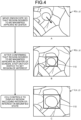
- FIG. 4 is a diagram illustrating an example of a method of setting the region-of-interest frame.
- FIG. 4A is a view illustrating an example of a surgical field image K(x, y) observed by the endoscope 5001.
- information regarding the timing (for example, time) of capturing the surgical field image will be omitted, and the surgical field image will be simply described as K(x, y).
- FIG. 4A is a view illustrating an example of a surgical field image K(x, y) observed by the endoscope 5001.
- FIG. 4b is a view illustrating an example of a state in which the orientation of the endoscope 5001 is adjusted so that the affected part desired to be set as the region-of-interest comes at the center of the surgical field image K(x, y), and the region-of-interest setting unit 20 has set a region-of-interest frame 110 indicating the region-of-interest.
- FIG. 4C is a view illustrating an example of a magnified surgical field image L(x, y) in which a region including the region-of-interest frame 110 is displayed in a state of being magnified at a predetermined magnification.
- the endoscope operator 5062 moves the endoscope 5001 so that the specific position desired to be magnified, such as the affected part, comes at the center (an example of a predetermined position) of the surgical field image K(x, y).
- the endoscope operator 5062 steps on the foot switch 5057 ( FIG. 1 ) to instruct the region-of-interest setting unit 20 to set the region-of-interest.
- a setting signal instructing the setting of the region-of-interest is generated.
- the region-of-interest setting unit 20 controls to display the region-of-interest frame 110 of a predetermined size at the center of the surgical field image K(x, y) as illustrated in FIG. 4B , thereby setting the region-of-interest.
- the size and shape of the region-of-interest frame 110 may be set flexibly, and details of which will be described below.
- the region-of-interest setting method performed by the region-of-interest setting unit 20 is not limited to the above-described method.
- a touch panel may be overlaid on the screen of the display device 50, and an operation on the touch panel may be detected to set a region-of-interest at a position where the touch panel has been operated.
- the position and shape of the region-of-interest may be set with a mouse.
- the region-of-interest setting unit 20 may set the position and shape of the region-of-interest based on an operation such as a gesture.
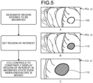
- FIG. 5 is a diagram illustrating another example of the method of setting the region-of-interest frame.
- FIG. 5A is a view illustrating an example of a surgical field image K(x, y) observed by the endoscope 5001.
- the endoscope operator 5062 designates the position of the region-of-interest by using an input device such as a touch panel or a mouse while monitoring the surgical field image K(x, y) displayed on the display device 50.
- the region-of-interest setting unit 20 controls to display region-of-interest instruction information 105 indicating the designated region so as to be superimposed on the surgical field image K(x, y).
- the region-of-interest setting unit 20 sets the region-of-interest frame 110 at the position of the input region-of-interest instruction information 105.
- the region-of-interest setting unit 20 controls to display the set region-of-interest frame 110 so as to be superimposed on the surgical field image K(x, y), as illustrated in FIG. 5B .
- the region-of-interest frame 110 may be a frame having a preset size and shape, or may be a closed region modeled upon the region-of-interest instruction information 105.
- the zoom processing unit 26 generates a magnified surgical field image L(x, y) obtained by magnifying the set region-of-interest frame 110 by a predetermined magnification, and displays the generated image as illustrated in FIG. 5C .
- the region-of-interest setting unit 20 may use the above-described three-dimensional map D(X, Y, Z) and may set the region-of-interest in consideration of conditions such that the distance in the three-dimensional space or the distance from the imaging system is within a certain range.
- the display mode of the region-of-interest frame 110 is not limited to that illustrated in FIGS. 4 and 5 . The variation of the display mode of the region-of-interest frame 110 will be described below (refer to FIG. 18 ).
- the region-of-interest setting unit 20 may set the position and shape of the region-of-interest based on an operation such as a gesture.
- the zoom processing unit 26 generates a magnified surgical field image L(x, y) obtained by magnifying the region including the region-of-interest frame 110 of the surgical field image K(x, y) by a predetermined magnification.
- the region-of-interest frame 110 is also displayed as an image magnified at a predetermined magnification.
- the display control unit 40 controls to output and display the generated magnified surgical field image L(x, y) to the display device 50.
- the surgeon 5061 performs an operation while observing the magnified surgical field image L(x, y) displayed on the display device 50.
- the medical observation system 10a repeats imaging/display of the surgical field image K(x, y) at a predetermined time interval ⁇ t. Every time the surgical field image K(x, y) is captured, the generation and display of a new magnified surgical field image L(x, y) will be repeated.
- the position and orientation of the endoscope 5001 might change in some cases together with the passage of observation time for the surgical field image K(x, y).
- the region-of-interest estimation unit 22 estimates the existence position of the region-of-interest on the surgical field image K(x, y).
- the zoom processing unit 26 generates a magnified surgical field image L(x, y) in which the estimated region-of-interest is magnified by a predetermined magnification.
- the display control unit 40 controls to output and display the magnified surgical field image L(x, y) to the display device 50.
- the medical observation system 10a continues to display the magnified surgical field image L(x, y) on the display device 50.
- the following is a description of a method of estimating, by the region-of-interest estimation unit 22, the existence position of the region-of-interest from within the surgical field image K(x, y) in a case where the position or orientation of the endoscope 5001 has changed.
- the region-of-interest estimation unit 22 estimates a to-be-observed position of the region-of-interest frame 110 within the surgical field image K(x, y, t + ⁇ t) at time t + ⁇ t, which is currently at a present position at time t.
- the region-of-interest estimation unit 22 specifies how a plurality of feature points in the vicinity of the set region-of-interest frame 110 has moved during a period from time t and time t + ⁇ t. Subsequently, the region-of-interest estimation unit 22 estimates the position of the region-of-interest based on the moving state of the specified feature point.
- the region set as a region-of-interest is typically the affected part as a target of operation.
- the affected part is likely to be surgically resected, bleeding, or severely deformed. Therefore, even when a feature point is set within a region-of-interest, the feature point might disappear with the passage of time. Therefore, when extracting a feature point from the surgical field image K(x, y) to which the region-of-interest has been set, it is desirable to extract the feature point from within the regions excluding the neighboring region of the region-of-interest.
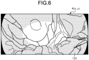
- FIG. 6 is an image illustrating an example in which a feature point extraction region has been set.
- the above-described map generation unit 15 sets a mask 120 at the periphery of the screen, avoiding the central portion of the screen on which the region-of-interest frame 110 has been set.
- the map generation unit 15 extracts a feature point only inside the set mask 120.
- the region of the mask 120 that has been set is distant from the region-of-interest frame 110 indicating the position of the region-of-interest, and thus is not likely to have a large deformation during an operation. Accordingly, it is possible, at inside portions of the mask 120, to stably detect feature points regardless of the passage of time. Since the feature points can be extracted stably, it is possible to enhance the stability of accuracy in estimating the three-dimensional map D(X, Y, Z) and the position and orientation of the endoscope 5001.
- the map generation unit 15 may have a function of removing objects such as surgical instruments and fingers registered in advance from the surgical field image K(x, y). This removal function is, for example, a function of performing image recognition for a pre-registered object and excluding the region in which the recognized object exists, from calculation.
- FIG. 7 is a view illustrating an example of an image displayed by the medical observation system 10a.
- the display control unit 40 controls to output and display the surgical field image K(x, y) monitored by the endoscope operator 5062 to a display device 50a (the second display region 52b).
- the display control unit 40 controls to output and display the magnified surgical field image L(x, y) monitored by the surgeon 5061 to a display device 50b (the first display region 52a) different from the display device 50a.
- the endoscope operator 5062 and the surgeon 5061 can dispose the display devices 50a and 50b respectively at positions that are easy to view.
- the surgeon 5061 can facilitate the progress of the surgery while observing the magnified surgical field image L(x, y).
- the endoscope operator 5062 can easily adjust the position of the endoscope 5001 while observing the surgical field image K(x, y).
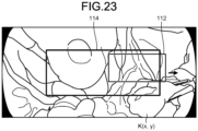
- the above-described region-of-interest frame 110 and a zoom frame 112 indicating the range of the magnified surgical field image L(x, y) may be displayed within the surgical field image K(x, y).
- the region-of-interest frame 110 and the zoom frame 112 move within the surgical field image K(x, y) together with the movement of the endoscope 5001.
- the endoscope operator 5062 can intensively confirm the surgical field image K(x, y) alone and can immediately confirm whether an appropriate range is being displayed in the magnified surgical field image L(x, y).
- displays of these may be independently turned ON/OFF by an operation instruction from the endoscope operator 5062.
- the medical observation system 10a generates the three-dimensional map D(X, Y, Z) and estimates the position and orientation of the endoscope 5001, and thus, can calculate the three-dimensional position of the feature points in the vicinity of the region-of-interest. Accordingly, by applying perspective-transform and/or rotational transform on the captured surgical field image K(x, y), it is also possible to generate and display a magnified surgical field image L(x, y) in which the region-of-interest is constantly viewed in a same direction.
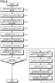
- FIG. 7 is a flowchart illustrating an example of the process flow performed by the medical observation system 10a.
- the imaging element 44a captures a surgical field image K(x, y) (step S10).
- the map generation unit 15 extracts feature points from the captured surgical field image K(x, y) (step S11) .
- the imaging element 44a captures the surgical field image K(x, y) at a predetermined timing, for example, after the passage of ⁇ t seconds (step S12).
- the map generation unit 15 extracts feature points from the captured surgical field image K(x, y) after the passage of ⁇ t seconds (step S13).
- the map generation unit 15 calculates the three-dimensional positions of the feature points and generates a three-dimensional map D(X, Y, Z) (step S14).
- the self-position estimation unit 16 estimates the position and orientation of the endoscope 5001 (step S15) .
- the region-of-interest setting unit 20 sets the region-of-interest in the surgical field image K(x, y) (step S16).
- the zoom processing unit 26 generates a magnified surgical field image L(x, y). Subsequently, the display control unit 40 controls to display the generated magnified surgical field image L(x, y) on the display device 50 (step S17) .
- the display control unit 40 determines whether there is an instruction to end the process (step S18). When it is determined that there is an end instruction (step S18: Yes), the medical observation system 10a ends the process of FIG. 8 . In contrast, when it is not determined that there is an end instruction (step S18: No), the process proceeds to step S19.
- the processing end instruction is determined by detecting an operation such as turning off the power switch (not illustrated) of the camera control unit 12a, for example.
- step S18 the imaging element 44a captures a surgical field image K(x, y) at a predetermined timing, for example, after the passage of ⁇ t seconds (step S19).
- the map generation unit 15 extracts feature points from the captured surgical field image K(x, y) after the passage of ⁇ t seconds (step S20).
- the map generation unit 15 calculates the three-dimensional position of the feature point and updates the three-dimensional map D(X, Y, Z) generated in step S14 (step S21).
- the self-position estimation unit 16 estimates the position and orientation of the endoscope 5001 (step S22) .
- the region-of-interest estimation unit 22 estimates the position of the region-of-interest in the surgical field image K(x, y) after the passage of ⁇ t seconds captured in step S19 (step S23). Thereafter, the process returns to step S17.
- the three-dimensional information generation unit 14 generates the three-dimensional map D(X, Y, Z) (three-dimensional information) regarding the surgical field, based on the surgical field image K(x, y) captured by the imaging device 42a.
- the region-of-interest setting unit 20 sets at least one region-of-interest in the surgical field image K(x, y) captured at a predetermined timing.
- the region-of-interest estimation unit 22 estimates the existence position of the region-of-interest in the surgical field image K(x, y) captured at a timing different from the predetermined timing.
- the zoom processing unit 26 magnified image generation unit
- the display control unit 40 outputs at least the magnified surgical field image L(x, y). Accordingly, even when the endoscope 5001 on which the imaging device 42a is mounted has changed its position or orientation, it is possible to continuously observe the affected part in a magnified state from a distant position.
- the display control unit 40 controls to display the surgical field image K(x, y) and the magnified surgical field image L(x, y). This enables display of both the magnified surgical field image L(x, y) that the surgeon 5061 desires to view and the surgical field image K(x, y) that the endoscope operator 5062 desires to view.
- the display control unit 40 controls to display the magnified surgical field image L(x, y) and the surgical field image K(x, y) on the two display devices 50a and 50b, respectively. Therefore, the surgeon 5061 and the endoscope operator 5062 can dispose the display devices 50a and 50b respectively at positions that are easy to view.
- the region-of-interest setting unit 20 designates a specific position of the surgical field image K(x, y) displayed on the display device 50 by the display control unit 40, as a region-of-interest, in a state where the specific position is aligned with a predetermined position of the display device 50 and on condition that the setting signal instructing the setting of the region-of-interest has occurred. Accordingly, the region-of-interest can be easily and reliably set by regular operations.
- the region-of-interest setting unit 20 sets a region-of-interest on the position instructed by the input device, on the surgical field image K(x, y) displayed on the display device 50 by the display control unit 40. Therefore, the region-of-interest can be easily and reliably set by an intuitive operation.
- the imaging device 42a includes one imaging element 44a, and the three-dimensional information generation unit 14 generates the three-dimensional map D(X, Y, Z) (three-dimensional information) of the surgical field based on at least two surgical field images K(x, y) captured by the imaging device 42a at different times.
- This makes it possible to continuously observe the affected part in a magnified state from a distant position by using the imaging device 42a having a simple configuration with a monocular camera alone.
- the imaging device 42a is mounted on the endoscope 5001. Therefore, when performing an operation or the like using the endoscope 5001, the surgeon 5061 can stably observe the affected part in a magnified state.
- the three-dimensional information generation unit 14 generates the three-dimensional map D(X, Y, Z) (three-dimensional information) of the surgical field based on the surgical field image K(x, y) obtained by capturing the surgical field. Subsequently, the region-of-interest setting unit 20 (setting unit) sets at least one region-of-interest within the surgical field image K(x, y) captured at a certain time.
- the region-of-interest estimation unit 22 estimates the existence position of the region-of-interest from within the surgical field image K(x, y) captured at a time different from the above-described time.
- the zoom processing unit 26 magnified image generation unit
- the display control unit 40 controls to display at least the magnified surgical field image L(x, y). This makes it possible to continuously observe the affected part in a magnified state.
- the endoscope 5001 incorporating the imaging device 42a may be equipped with an acceleration sensor such as a gyro sensor. By monitoring the output of the acceleration sensor, the position and orientation of the endoscope 5001 can be measured in real time. This would make it possible to measure the position and orientation of the endoscope 5001 without capturing two images at different times by the imaging device 42a, enabling estimation of the position of the region-of-interest.
- an acceleration sensor such as a gyro sensor
- the configuration of the medical observation system 10a is not limited to the configuration described in the first embodiment, and various modifications can be implemented. Hereinafter, other embodiments of the medical observation system will be described one by one.
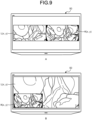
- FIG. 9 is a view illustrating an example of a display mode of an image output by the display control unit 40 to the display device 50. That is, the first embodiment includes exemplary cases where the display control unit 40 outputs the magnified surgical field image L(x, y) alone to the display device 50, and where the magnified surgical field image L(x, y) and the surgical field image K(x, y) are output to the mutually different display devices 50a and 50b, respectively.
- the display modes of output images are not limited to these.
- FIG. 9A illustrates an example in which the display control unit 40 controls to display the surgical field image K(x, y) and the magnified surgical field image L(x, y) adjacent to each other (side by side) on the display device 50. That is, the magnified surgical field image L(x, y) is displayed in the first display region 52a and the surgical field image K(x, y) is displayed in the second display region 52b, which are set on the display screen of the display device 50.
- the surgeon 5061 can proceed with the operation while observing the magnified surgical field image L(x, y), and the endoscope operator 5062 can adjust the position of the endoscope 5001 while observing the surgical field image K(x, y).
- FIG. 9B is an example in which the display control unit 40 controls to display, on the display device 50, an image obtained by superimposing (using PinP) the surgical field image K(x, y) on a part of the magnified surgical field image L(x, y).
- the second display region 52b is superimposed on a part of the first display region 52a.
- the surgeon 5061 can proceed with the operation while observing the magnified surgical field image L(x, y), and the endoscope operator 5062 can adjust the position of the endoscope 5001 while observing the surgical field image K(x, y).
- the position where the surgical field image K(x, y) is superimposed is not limited to the example of FIG. 9B , and may be any of the upper left, upper right, and lower right positions of the magnified surgical field image L(x, y).
- the display control unit 40 controls to display the surgical field image K(x, y) and the magnified surgical field image L(x, y) on one display device 50, with the two images adjacent to each other. This enables display of both the magnified surgical field image L(x, y) that the surgeon 5061 desires to view and the surgical field image K(x, y) that the endoscope operator 5062 desires to view.
- the display control unit 40 controls to display the surgical field image K(x, y) so as to be superimposed on a part of the magnified surgical field image L(x, y), on one display device 50.
- This enables display of both the magnified surgical field image L(x, y) that the surgeon 5061 desires to view and the surgical field image K(x, y) that the endoscope operator 5062 desires to view.
- the magnified surgical field image L(x, y) can be displayed as large as possible.
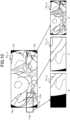
- FIG. 10 is a view illustrating an example of a process performed when a zoom frame reaches an edge of the surgical field image K(x, y) with the movement of the endoscope 5001.
- the zoom frame is a frame indicating a display range of the magnified surgical field image L(x, y).
- the surgical field image K(x, y) observed by the endoscope 5001 includes vignetting regions 130 having circular shadings, in peripheral portions in the image. Since the vignetting regions 130 are regions formed by the absence of light, they are observed as black regions as illustrated in FIG. 10A .
- the zoom frame might reach the edge of the surgical field image K(x, y).
- the medical observation system 10a takes one of three processing modes prepared in advance.
- FIG. 10B is an example in which when a zoom frame 112a reaches the edge of the surgical field image K(x, y), the region without image information is displayed in black. That is, the zoom processing unit 26 generates a magnified surgical field image L(x, y) in which a predetermined pixel value (for example, pixel value zero representing black) is stored in the region of the zoom frame 112a exceeding the edge of the surgical field image K(x, y) and overlapping with the vignetting region 130. Subsequently, the display control unit 40 controls to display the generated magnified surgical field image L(x, y).
- a predetermined pixel value for example, pixel value zero representing black
- the display control unit 40 controls to display the magnified surgical field image L(x, y) in which a pixel value of zero indicating the color of black is interpolated to the region inside the zoom frame 112a where the image information is missing.
- the endoscope operator 5062 can immediately recognize that the position of the endoscope 5001 has reached the edge of the surgical field image K(x, y) because of expansion of the black region.
- the endoscope operator 5062 can regenerate the magnified surgical field image L(x, y) without any vignetting by adjusting the position of the endoscope 5001.
- FIG. 10C is an example in which the screen edge is continuously displayed as it is when the zoom frame 112a has reached the edge of the surgical field image K(x, y). That is, in a case where the edge of the zoom frame 112a, that is, the edge of the magnified surgical field image L(x, y) is aligned with the edge of the surgical field image K(x, y), the zoom processing unit 26 generates the magnified surgical field image L(x, y) while holding the position of the zoom frame 112a even in a case where the endoscope 5001 has further moved beyond the edge of the surgical field image K(x, y). Subsequently, the display control unit 40 controls to display the generated magnified surgical field image L(x, y).
- the display control unit 40 controls to move the zoom frame 112a to the position of a zoom frame 112b so as to display the image inside the moved zoom frame 112b as a magnified surgical field image L(x, y). That is, at this time, the left end of the zoom frame 112b is aligned with the left end of the surgical field image K(x, y).
- the display region of the magnified surgical field image L(x, y) can be held at the end of the surgical field image K(x, y) regardless of the movement of the endoscope 5001.
- FIG. 10D illustrates an example in which the zoom processing unit 26 stops the generation of the magnified surgical field image L(x, y) in a case where the zoom frame 112a has reached the end of the surgical field image K(x, y). At this time, the display control unit 40 controls to display the surgical field image K(x, y).
- the display of the magnified surgical field image L(x, y) is canceled, and whereby the endoscope operator 5062 can immediately recognize the fact that the imaging range of the endoscope 5001 has reached the end of the surgical field image K(x, y).
- the endoscope operator 5062 can regenerate the magnified surgical field image L(x, y) without any vignetting by adjusting the position of the endoscope 5001.
- the zoom processing unit 26 (magnified image generation unit) generates the magnified surgical field image L(x, y) that stores a predetermined pixel value in the region beyond the edge and the region overlapping the vignetting region in the zoom frame 112a. Therefore, the endoscope operator 5062 can immediately recognize the fact that the zoom frame 112a has reached the edge of the surgical field image K(x, y). The endoscope operator 5062 can also adjust the position of the endoscope 5001 to suppress an occurrence of vignetting.
- the zoom processing unit 26 (magnified image generation unit) generates a magnified surgical field image L(x, y) in which the edge of the magnified surgical field image L(x, y) is aligned with the edge of the surgical field image K (x, y). Therefore, it is possible to continuously display the magnified surgical field image L (x, y) without any vignetting.
- the zoom processing unit 26 stops generation of the magnified surgical field image L(x, y) in a case where the zoom frame 112a has reached the edge of the surgical field image K(x, y) or comes to a position overlapping the vignetting region of the surgical field image K(x, y). Therefore, the endoscope operator 5062 can immediately recognize the fact that the imaging range of the endoscope 5001 has reached the edge of the surgical field image K(x, y). The endoscope operator 5062 can also adjust the position of the endoscope 5001 to suppress an occurrence of vignetting.
- the medical observation system 10a has been described assuming that the imaging device 42a has one imaging element 44a.
- the configuration of the imaging device is not limited to this.
- FIG. 11 is a diagram illustrating an example of a schematic configuration of a medical observation system 10b in which an imaging device 42b includes an imaging element 44b having an image plane phase difference sensor 46. Note that a part of illustration corresponding to FIG. 2 is omitted in FIG. 11 . Accordingly, unless otherwise specified, the omitted portion has the same configuration as that of FIG. 2 .
- the image plane phase difference sensor 46 has a configuration in which pixels for distance measurement are discretely arranged in the imaging element 44b.
- the map generation unit 15 can extract depth information (distance information), that is, information regarding a depth (distance) to an imaged object 100 from the image plane phase difference information output by the image plane phase difference sensor 46. This leads to effective utilization of SLAM technology. Note that the image plane phase difference sensor 46 can obtain depth information from a single captured image.
- the depth information can be obtained from one captured surgical field image K(x, y). This makes it possible to measure the three-dimensional position of an object with high accuracy even when the object is moving.
- FIG. 12 is a diagram illustrating an example of a schematic configuration of a medical observation system 10c in which an imaging device 42c includes two imaging elements 44c and 44d.
- the two imaging elements 44c and 44d are arranged in a state of maintaining a predetermined relative relationship and capture images of different locations of an affected part so as to partially overlap each other. More specifically, the imaging elements 44c and 44d respectively acquire image signals for the right eye and the left eye, corresponding to stereoscopic vision.
- Note that a part of illustration corresponding to FIG. 2 is omitted in FIG. 12 . Accordingly, unless otherwise specified, the omitted portion has the same configuration as that of FIG. 2 .
- the camera control unit 12b includes a depth information generation unit 30 in addition to the configuration described with reference to FIG. 2 .
- the depth information generation unit 30 generates depth information by matching two surgical field images individually captured by the two imaging elements 44c and 44d.
- the map generation unit 15 can generate the three-dimensional map D(X, Y, Z) by using the depth information generated by the depth information generation unit 30 and the surgical field images individually captured by the imaging elements 44c and 44d, with application of the SLAM technology. Furthermore, since the two imaging elements 44c and 44d can perform imaging at the same time, depth information can be obtained from the two images obtained by one shot of imaging. Therefore, even when the object is moving, the three-dimensional position of the object can be measured with high accuracy.
- the imaging device 42c includes the two imaging elements 44c and 44d that image different ranges partially overlapping each other, and the three-dimensional information generation unit 14 generates three-dimensional information of the surgical field based on the two surgical field images K(x, y) captured by the two imaging elements 44c and 44d at the same time. Therefore, depth information can be obtained from the two surgical field images K(x, y) obtained by one imaging, making it possible to measure the three-dimensional position of the surgical field with high accuracy even when the surgical field is moving.
- FIG. 13 is a diagram illustrating an example of a schematic configuration of a medical observation system 10d in which the imaging device 42c includes two imaging elements, and a camera control unit 12c includes a tracking processing unit 34. Note that a part of illustration corresponding to FIG. 2 is omitted in FIG. 13 . Accordingly, unless otherwise specified, the omitted portion has the same configuration as that of FIG. 2 .
- the camera control unit 12c of the medical observation system 10d includes a depth information generation unit 30, a three-dimensional information generation unit 32, a tracking processing unit 34, and a zoom region calculation unit 36.
- the three-dimensional information generation unit 32 is provided in place of the three-dimensional information generation unit 14 ( FIG. 2 ), and generates three-dimensional information of the surgical field image K(x, y) based on the depth information generated by the depth information generation unit 30.
- the tracking processing unit 34 is provided in place of the three-dimensional map data storage unit 24 ( FIG. 2 ), and calculates a difference in position and orientation of the imaging device 42c using a method of superimposing two point clouds, such as iterative closest point (ICP) method, based on three-dimensional information of the immediately preceding frame and three-dimensional information of the current frame.
- the zoom region calculation unit 36 is provided in place of the region-of-interest estimation unit 22 ( FIG.
- the zoom processing unit 26 ( FIG. 2 ) described above performs zoom processing on the region calculated by the zoom region calculation unit 36, and generates a magnified surgical field image L(x, y).
- the region-of-interest in the surgical field image K(x, y) can be stably tracked (followed) regardless of the movement of the imaging device 42c.
- FIG. 14 is a diagram illustrating an example of a schematic configuration of a medical observation system 10e in which an imaging device 42d includes an imaging element 44a and a depth sensor 48. Note that a part of illustration corresponding to FIG. 2 is omitted in FIG. 14 . Accordingly, unless otherwise specified, the omitted portion has the same configuration as that of FIG. 2 .
- the depth sensor 48 is also referred to as a 3D sensor that measures the distance to the subject.
- the depth sensor 48 is also referred to as a time of flight (ToF) sensor that receives reflected light of infrared light, for example, emitted toward the subject, and thereby measures the flight time of light to obtain the distance to the subject.
- the depth sensor 48 is actualized by using a pattern projection method (Structured Light projection) in which an image of projected light having a plurality of different geometric patterns applied to the subject is captured so as to measure the distance to the subject.
- the map generation unit 15 extracts depth information (distance information) to the captured object 100 based on the surgical field image K(x, y) captured by the imaging element 44a and the distance output by the depth sensor 48. More specifically, the map generation unit 15 calculates which pixel of the surgical field image K(x, y) captured by the imaging element 44a corresponds to the point measured by the depth sensor 48. Subsequently, the map generation unit 15 generates a three-dimensional map D(X, Y, Z) (three-dimensional information) of the surgical field. This leads to effective utilization of SLAM technology.
- the imaging device 42d includes the one imaging element 44a and the depth sensor 48 (distance measuring device) that measures the distance to the object, and the three-dimensional information generation unit 14 generates the three-dimensional map D(X, Y, Z) (three-dimensional information) of the surgical field based on the image captured by the imaging element 44a and the distance measured by the depth sensor 48. This makes it possible to measure the distance to the surgical field easily and reliably.
- FIG. 15 is a diagram illustrating an example of a schematic configuration of a medical observation system 10f in which an imaging device 42d includes an imaging element 44a and a depth sensor 48, and a camera control unit 12d includes a tracking processing unit 34. Note that a part of illustration corresponding to FIG. 2 is omitted in FIG. 15 . Accordingly, unless otherwise specified, the omitted portion has the same configuration as that of FIG. 2 .
- the camera control unit 12d of the medical observation system 10f includes a three-dimensional information generation unit 32, a tracking processing unit 34, and a zoom region calculation unit 36.
- the three-dimensional information generation unit 32 is provided in place of the three-dimensional information generation unit 14 ( FIG. 2 ), and performs matching of two pieces of distance information (for example, distance images storing pixel values corresponding to the distance to the subject) measured by the depth sensor 48 from different positions, thereby obtaining the moving state of the surgical field.
- the tracking processing unit 34 is provided in place of the three-dimensional map data storage unit 24 ( FIG. 2 ), and calculates a difference in position/orientation of the imaging device 42c based on the moving state of the surgical field described above.
- the zoom region calculation unit 36 is provided in place of the region-of-interest estimation unit 22 ( FIG.
- the zoom processing unit 26 ( FIG. 2 ) described above performs zoom processing on the region calculated by the zoom region calculation unit 36, and generates a magnified surgical field image L(x, y).
- the region-of-interest in the surgical field image K(x, y) can be stably tracked (followed) regardless of the movement of the imaging device 42d.
- FIG. 16 is a view illustrating an example in which a plurality of region-of-interest frames 110a and 110b is set in the surgical field image K(x, y).
- the region-of-interest setting unit 20 may set a plurality of regions-of-interest in the surgical field image K(x, y). For example, when it is necessary to pay attention to a plurality of affected parts, the region-of-interest setting unit 20 sets region-of-interest frames 110a and 110b indicating individual regions-of-interest based on an instruction from the endoscope operator 5062. Subsequently, the display control unit 40 controls to individually display, on the display device 50, two magnified surgical field images L(x, y) in which the region of the zoom frame corresponding to each of the region-of-interest frames 110a and 110b is magnified.
- the region-of-interest setting unit 20 sets a plurality of regions-of-interest. Therefore, it is possible to display the magnified surgical field image L(x, y) in which a plurality of regions-of-interest is magnified.
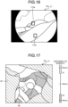
- FIG. 17 is a view illustrating an example in which a region in a predetermined distance range is presented by highlighted display in a surgical field image K(x, y).
- the region-of-interest setting unit 20 displays a predetermined distance range region in the surgical field image K(x, y) with a predetermined coloring, as illustrated in FIG. 17.
- FIG. 17 illustrates an example in which a region R1 having a distance shorter than a distance d1 and a region R2 having a distance longer than a distance d2 are displayed in different colors. Note that this is a process performed to restrict a distance range to the region-of-interest to a range from the distance d1 to the distance d2, for the purpose of facilitating the setting of the region-of-interest.
- the values of the distance d1 and the distance d2 can be preferably set, as illustrated in FIG. 17 , using a method in which the region-of-interest setting unit 20 controls to display a distance scale in the vicinity of the surgical field image K(x, y), and the endoscope operator 5062 manipulates an input device such as a mouse or a touch panel.
- the region-of-interest setting unit 20 performs real time coloring display of the region R1 and the region R2 on the surgical field image K(x, y).
- the manipulator points, with the input device, to the position of the distance to be set on the distance scale so as to set the distance d1 or the distance d2.
- the manipulator next drags the input device toward the farther direction or the closer direction on the distance scale while performing the pointing with the input device.
- the region-of-interest setting unit 20 displays a color attached in the dragged distance range on the distance scale as illustrated in FIG. 17 .
- GUI graphical user interface
- the manipulator can easily recognize the region corresponding to the distance range set by oneself, in the surgical field image K(x, y). Note that the method of displaying the set distance range on the distance scale is not limited to the method illustrated in FIG. 17 , and other display modes may be used as long as the set distance range is clearly indicated.
- the display control unit 40 controls to display, on the display device 50, the surgical field image K(x, y) in which the region R1 and the region R2 are displayed with individual colors.
- the endoscope operator 5062 sets the region-of-interest following the above procedure (refer to FIG. 4 ) while viewing the surgical field image K(x, y) in which the region R1 and the region R2 are displayed in individual colors.
- the region-of-interest setting unit 20 (setting unit) further includes a function of designating a distance range containing a region-of-interest, and sets the region-of-interest within the designated distance range. Accordingly, the endoscope operator 5062 can set the region-of-interest more easily.
- FIG. 18 is a view illustrating an example of a display mode of region-of-interest frames 110c to 110g set in the surgical field image K(x, y).
- FIG. 18A is an example in which the region-of-interest frame 110c is displayed in a circular region.
- FIG. 18B is an example in which the region-of-interest frame 110d is illustrated as a colored (highlighted) closed region.
- FIG. 18C is an example in which the region-of-interest frame 110e is illustrated as a symbol.
- FIG. 18D is an example in which the region-of-interest frame 110f is illustrated as a closed curve.
- FIG. 18E is an example in which the region-of-interest frame 110g and regions having the same distance as the set position of the region-of-interest frame 110g are both displayed with coloring. According to the display mode of FIG.
- the endoscope operator 5062 can recognize that other regions exist at a same distance position as the region-of-interest. This enables gripping the endoscope 5001 further carefully so as to avoid interrupting the tracking to the region-of-interest in a case where the endoscope 5001 is erroneously oriented in a direction of another region.
- the endoscope operator 5062 is only required to preliminarily set, in the region-of-interest setting unit 20, in which mode the region-of-interest frame is to be displayed.
- the method of setting the region-of-interest frames 110c to 110g are to preferably be set following the method described with reference to FIG. 4 or 5 .
- the region-of-interest frame is set as a closed region having an arbitrary shape, in particular, as illustrated in FIGS. 18B, 18D, and 18E , it is efficient to directly set the position and shape of the region-of-interest frame on the surgical field image K(x, y) displayed on the display device 50, as illustrated in FIG. 5 .
- the region-of-interest frames 110c to 110g of a mode with high visibility for the manipulator can be displayed in the set region-of-interest.
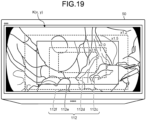
- FIG. 19 is a diagram illustrating an example of a method for setting the zoom frame 112.
- the endoscope operator 5062 may set the magnification used for magnifying the surgical field image K(x, y).
- Setting of magnification can be performed by a method, for example, in which the zoom processing unit 26 in FIG. 2 causes the display control unit 40 to display a plurality of selectable zoom frames 112 (112c to 112f) to be superimposed on the surgical field image K(x, y) on the display device 50 so as to allow the manipulator to designate one of the zoom frames.
- FIG. 19 illustrates an example in which the zoom frame 112e indicating 1.5x magnification is designated.
- the zoom frame 112 can be selected, for example, by operating an input device such as a hand switch provided near the endoscope 5001.
- the zoom processing unit 26 may generate the magnified surgical field image L(x, y) at a magnification appropriate for the distance to the region-of-interest. That is, the zoom processing unit 26 calculates the distance to the region-of-interest, for example, based on the three-dimensional map D(X, Y, Z) generated by the three-dimensional information generation unit 14 and stored in the three-dimensional map data storage unit 24. Subsequently, the magnification used for generating the magnified surgical field image L(x, y) is determined in accordance with the calculated distance to the region-of-interest.
- the imaging device 42a may include an auto focus (AF) function and the distance to the region-of-interest may be calculated by focusing, by the imaging device 42a, on the position of the region-of-interest estimated by the region-of-interest estimation unit 22.
- the magnification can be set to high magnification when the distance to the region-of-interest is long, and can be set to low magnification when the distance to the region-of-interest is short, for example.
- the endoscope operator 5062 can easily set the magnification by selecting one zoom frame from the plurality of zoom frames 112c to 112f displayed on the display device 50.
- the zoom processing unit 26 (magnified image generation unit) generates the magnified surgical field image L(x, y) at a magnification appropriate for the distance to the region-of-interest. Therefore, even when the endoscope 5001 moves in the anteroposterior direction with respect to the affected part, the affected part can be continuously observed with a constant size.
- FIG. 20 is a view illustrating an example of a method of displaying the zoom frame 112 when the medical observation system 10a is applied.
- the zoom processing unit 26 may cause the display control unit 40 to display the zoom frame 112 to be superimposed on the surgical field image K(x, y) displayed on the display device 50.
- FIG. 20A is an example in which the zoom frame 112 is displayed within the surgical field image K(x, y) displayed to be superimposed on a part of the magnified surgical field image L(x, y).
- FIG. 20B is an example in which the zoom frame 112 is displayed within the surgical field image K(x, y) displayed adjacent to the magnified surgical field image L (x, y).
- FIG. 20C is an example in which the zoom frame 112 is displayed within the surgical field image K(x, y) displayed on the display device 50a different from the display device 50b displaying the magnified surgical field image L(x, y).
- the endoscope operator 5062 can easily confirm the position of the zoom frame 112. This enables the endoscope operator 5062 to predict the arrival of the zoom frame 112 at the screen edge, making it possible to prevent an occurrence of vignetting that occurs when the display range of the magnified surgical field image L(x, y) exceeds the edge of the surgical field image K(x, y).
- the medical observation system 10a described in the first embodiment in order to improve the visibility of the surgical field image K(x, y) and the magnified surgical field image L(x, y) displayed on the display device 50, it is allowable to perform camera shake correction processing and exposure amount adjustment for these images.
- the camera shake correction processing is performed by the zoom processing unit 26 of FIG. 2 , for example, and the exposure amount adjustment is performed by the development processing unit 18 of FIG. 2 .
- the zoom processing unit 26 calculates the movement amount and movement direction of an object appearing in the image across a plurality of captured images, with respect to the surgical field image K(x, y) and the magnified surgical field image L(x, y).
- the captured image is electronically shifted in accordance with the calculated movement amount and movement direction, thereby generating an image in which camera shake has been corrected.
- the magnified surgical field image L(x, y) is an observation image of a region narrower than the surgical field image K(x, y), and thus, has a larger amount of image blurring caused by camera shake. Therefore, it is desirable that the camera shake correction on the magnified surgical field image L(x, y) performed by the zoom processing unit 26 will have higher camera shake correction effects compared to the camera shake correction for the surgical field image K(x, y).
- the development processing unit 18 may set a digital gain and a gamma curve separately for the surgical field image K(x, y) and the magnified surgical field image L(x, y), thereby individually adjusting the exposure amount.
- the zoom processing unit 26 performs camera shake correction onto the surgical field image K(x, y) and the magnified surgical field image L(x, y). Therefore, even in a case where camera shake occurs in the surgical field image K(x, y) captured by the endoscope 5001, it is possible to obtain a surgical field image K(x, y) and a magnified surgical field image L(x, y) having high visibility due to camera shake correction.
- FIG. 21 is a view illustrating an example of a schematic configuration of a microscopic surgery system 5300 to which the techniques according to the present disclosure is applicable.
- the microscopic surgery system 5300 includes a microscope device 5301, a control device 5317, and a display device 50.
- a "user" means a surgeon, an operator, an assistant, or any other medical staff who uses the microscopic surgery system 5300.
- the microscope device 5301 includes a microscope unit 5303 for performing magnified observation of an observation target (patient's surgical site), an arm unit 5309 that supports, at its distal end, the microscope unit 5303, and a base unit 5315 that supports the proximal end of the arm unit 5309.
- the microscope unit 5303 includes a tubular portion 5305 that has a substantially cylindrical shape, and an imaging unit (not illustrated) provided inside the tubular portion 5305.
- the microscope unit 5303 is an electronic imaging microscope unit (also referred to as a video microscope unit) that electronically captures an image using the imaging unit.
- the imaging unit is an example of an imaging device in the present disclosure.
- a cover glass slip is provided to protect the imaging unit inside.
- the light coming from the observation target (hereinafter, also referred to as observation light) passes through the cover glass slip and is incident on the imaging unit inside the tubular portion 5305.
- a light source being a light emitting diode (LED) may be provided inside the tubular portion 5305, and light may be applied to the observation target from the light source through the cover glass slip, at the time of imaging.
- LED light emitting diode
- the imaging unit includes: an optical system that collects observation light; and an imaging element that receives the observation light collected by the optical system.
- the optical system includes a combination of a plurality of lenses such as a zoom lens and a focus lens, and its optical characteristics are adjusted so that observation light is focused on a light receiving surface of the imaging element.
- the imaging element receives the observation light and photoelectrically converts the received light to generate a signal corresponding to the observation light, that is, an image signal corresponding to the observation image.
- An example of an applicable imaging element is a device capable of color imaging having a Bayer array.
- the imaging element may be various known imaging elements such as a CMOS image sensor or a CCD image sensor.
- the image signal generated by the imaging element is transmitted to the control device 5317 as RAW data.
- the transmission of this image signal may be preferably performed by optical communication. This is because, at the surgical site, the surgeon performs surgery while observing the condition of the affected part using captured images, and thus displaying moving images of the surgical field in real time as much as possible is demanded for safer and more reliable surgery.
- optical communication By transmitting the image signal by optical communication, it is possible to display the captured image with low latency.
- the imaging unit may include a drive mechanism that moves the zoom lens and the focus lens of the optical system along the optical axis. By appropriately moving the zoom lens and the focus lens by the drive mechanism, it is possible to adjust the magnification of the captured image and the focal length at the time of imaging. Furthermore, the imaging unit may be equipped with various functions that can be generally provided in an electronic imaging microscope unit, such as an auto exposure (AE) function and an AF function.
- AE auto exposure
- AF AF function
- the imaging unit may be configured as a single-plate imaging unit having one imaging element, or may be configured as a multi-plate imaging unit having a plurality of imaging elements.
- each of imaging elements may generate an image signal corresponding to one color of RGB, and a color image may be obtained by combining these individual color image signals.
- the imaging unit may include a pair of imaging elements for acquiring image signals individually for the right eye and the left eye corresponding to stereoscopic vision (3D display). The 3D display enables the surgeon to grasp the depth of the living tissue more accurately in the surgical field.
- a plurality of optical systems may be provided corresponding to each of the imaging elements.
- the arm unit 5309 has a configuration in which a plurality of links (first link 5313a to sixth link 5313f) is swivelably coupled to each other via a plurality of joints (first joint 5311a to sixth joint 5311f).
- the first joint 5311a has a substantially columnar shape, and swivelably supports, at its distal end (lower end), an upper end of the tubular portion 5305 of the microscope unit 5303 about a rotation axis (first axis O 1 ) parallel to the central axis of the tubular portion 5305.
- first axis O 1 a rotation axis
- the first joint 5311a can be configured such that the first axis O 1 is aligned with the optical axis of the imaging unit of the microscope unit 5303. With this configuration, swivel movement of the microscope unit 5303 about the first axis O 1 will make it possible to change the field of view so as to rotate the captured image.
- the first link 5313a fixedly supports the first joint 5311a at the distal end.
- the first link 5313a is a rod-shaped member having a substantially L-shape. Having one side of the distal end side extending in a direction orthogonal to the first axis O 1 , the first link 5313a is connected to the first joint 5311a with an end of the one side being in contact with an upper end of an outer circumference of the first joint 5311a.
- the second joint 5311b is connected to the end of the other side on the proximal end side of the substantially L-shape of the first link 5313a.
- the second joint 5311b has a substantially columnar shape, and swivelably supports, at its distal end, the proximal end of the first link 5313a about a rotation axis (second axis O 2 ) orthogonal to the first axis O 1 .
- the distal end of the second link 5313b is fixedly connected to the proximal end of the second joint 5311b.
- the second link 5313b is a rod-shaped member having a substantially L-shape. Having one side of the distal end side extending in a direction orthogonal to the second axis O 2 , the second link 5313b has an end of the one side fixedly connected to the proximal end of the second joint 5311b.
- the third joint 5311c is connected to the other side of the proximal end side of the substantially L-shape of the second link 5313b.
- the third joint 5311c has a substantially columnar shape, and swivelably supports, at its distal end, the proximal end of the second link 5313b about a rotation axis (third axis O 3 ) orthogonal to the first axis O 1 and the second axis O 2 .
- the distal end of the third link 5313c is fixedly connected to the proximal end of the third joint 5311c.
- the third link 5313c is configured so that its distal end side has a substantially columnar shape, and the proximal end of the third joint 5311c is fixedly connected to the distal end of the columnar shape so as to have a substantially same central axis.
- the proximal end side of the third link 5313c has a prismatic shape, with its end being connected to the fourth joint 5311d.
- the fourth joint 5311d has a substantially columnar shape, and swivelably supports, at its distal end, the proximal end of the third link 5313c about a rotation axis (fourth axis O 4 ) orthogonal to the third axis O 3 .
- the distal end of the fourth link 5313d is fixedly connected to the proximal end of the fourth joint 5311d.
- the fourth link 5313d is a rod-shaped member that extends substantially linearly. Extending so as to be orthogonal to the fourth axis O 4 , the fourth link 5313d is fixedly connected to the fourth joint 5311d so as to bring an end of the distal end in contact with a substantially columnar side surface of the fourth joint 5311d.
- the fifth joint 5311e is connected to the proximal end of the fourth link 5313d.
- the fifth joint 5311e has a substantially columnar shape, and swivelably supports, at its distal end, the proximal end of the fourth link 5313d about a rotation axis (fifth axis O 5 ) parallel to the fourth axis O 4 .
- the distal end of the fifth link 5313e is fixedly connected to the proximal end of the fifth joint 5311e.
- the fourth axis O 4 and the fifth axis O 5 are rotation axes that allows movement of the microscope unit 5303 in the up-down direction.
- the fifth link 5313e has a configuration including a combination of a first member having a substantially L-shape and having one side extending in the vertical direction and the other side extending in the horizontal direction, and a rod-shaped second member and extending vertically downward from a portion of the first member extending in the horizontal direction.
- the proximal end of the fifth joint 5311e is fixedly connected to the vicinity of the upper end of the portion extending in the vertical direction of the first member of the fifth link 5313e.
- the sixth joint 5311f is connected to the proximal end (lower end) of the second member of the fifth link 5313e.
- the sixth joint 5311f has a substantially columnar shape, and swivelably supports, at its distal end, the proximal end of the fifth link 5313e about a rotation axis (sixth axis O 6 ) parallel to the vertical direction.
- the distal end of the sixth link 5313f is fixedly connected to the proximal end of the sixth joint 5311f.
- the sixth link 5313f is a rod-shaped member extending in the vertical direction, with a proximal end of which being fixedly connected to the upper surface of the base unit 5315.
- the rotatable ranges of the first joint 5311a to the sixth joint 5311f are appropriately set so as to enable a desired movement of the microscope unit 5303.
- the arm unit 5309 having the configuration described above can achieve a movement of six degrees of freedom, namely, three degrees of freedom of translation and three degrees of freedom of rotation regarding the movement of the microscope unit 5303.
- the configuration of the arm unit 5309 that achieves six degrees of freedom regarding the movement of the microscope unit 5303 it is possible to freely control the position and orientation of the microscope unit 5303 within a movable range of the arm unit 5309. This makes it possible to observe the surgical field from any angle, enabling execution of the surgery further smoothly.
- the configuration of the arm unit 5309 illustrated in the figure is only an example, and the number and shape (length) of the links constituting the arm unit 5309, the number of joints, the arrangement position, the direction of the rotation axis, or the like, may be appropriately designed so that the desired degree of freedom can be achieved.
- the arm unit 5309 in order to freely move the microscope unit 5303, the arm unit 5309 is preferably configured to have six degrees of freedom.
- the arm unit 5309 may be configured to have more degrees of freedom (namely, a redundant degree of freedom). In a case where the redundant degree of freedom exists, it is possible, in the arm unit 5309, to change the orientation of the arm unit 5309 while the position and orientation of the microscope unit 5303 are fixed. This makes it possible to achieve more convenient control for the surgeon, including controlling the orientation of the arm unit 5309 so as to prevent the arm unit 5309 from interfering with the field of view of the surgeon viewing the display device 50.
- the first joint 5311a to the sixth joint 5311f can include an actuator equipped with a drive mechanism such as a motor, and an encoder to detect a rotation angle at each of the joints, or the like.
- a drive mechanism such as a motor
- an encoder to detect a rotation angle at each of the joints, or the like.
- the control device 5317 can grasp the current orientation of the arm unit 5309 and the current position and orientation of the microscope unit 5303 based on the information regarding the rotation angle of each of joints detected by the encoder.
- control device 5317 uses the grasped information to calculate control values (for example, rotation angle or generated torque) for each of joints so that the microscope unit 5303 achieves a desired movement, and drives the drive mechanism of each of joints based on the control values.
- control values for example, rotation angle or generated torque
- the method for controlling the arm unit 5309 by the control device 5317 is not limited, and various known control methods such as force control or position control may be applied.
- the surgeon appropriately performs operation input through an input device (not illustrated), and the control device 5317 appropriately controls the drive of the arm unit 5309 based on the operation input, so as to control the position and orientation of the microscope unit 5303.
- the control device 5317 appropriately controls the drive of the arm unit 5309 based on the operation input, so as to control the position and orientation of the microscope unit 5303.
- an input device such as a foot switch that can be operated even when the surgeon is holding the surgical tool by hand.
- the operation input may be performed in a noncontact operation based on a gesture detection or line-of-sight detection using a wearable device or a camera provided in the operating room.
- the arm unit 5309 may be operated by a master-slave method.
- the arm unit 5309 can be remotely controlled by the user via an input device installed at a location away from the operating room.
- a power assist control in which the actuators of the first joint 5311a to the sixth joint 5311f are driven so as to achieve smooth movement of the arm unit 5309 in response to an external force received from the user.
- the drive of the arm unit 5309 may be controlled so as to perform a pivot operation.
- the pivot operation is an operation of moving the microscope unit 5303 so that the optical axis of the microscope unit 5303 constantly faces a predetermined point in space (hereinafter, referred to as a pivot point). With the pivot operation, it is possible to observe an identical observation position from various directions, enabling observation of the affected part in more detail.
- focal length adjustment is disabled in the microscope unit 5303
- the microscope unit 5303 will move on a hemisphere (schematically illustrated in FIG. 21 ) having a radius corresponding to the focal length centered on the pivot point, leading to acquisition of a clear image even when the observation direction is changed.
- focal length adjustment it is allowable to perform the pivot operation with a variable distance between the microscope unit 5303 and the pivot point.
- the control device 5317 calculates the distance between the microscope unit 5303 and the pivot point based on the information regarding the rotation angle of individual joints detected by the encoder, and automatically adjusts the focal length of the microscope unit 5303 based on the calculation result.
- the microscope unit 5303 includes an AF function
- the focal length may be automatically adjusted by the AF function each time the distance between the microscope unit 5303 and the pivot point changes due to the pivot operation.
- the control device 5317 By controlling the operations of the microscope device 5301 and the display device 50, the control device 5317 comprehensively controls the operation of the microscopic surgery system 5300. For example, by controlling to operate the actuators of the first joint 5311a to the sixth joint 5311f with a predetermined control method, the control device 5317 controls the drive of the arm unit 5309. Furthermore, for example, by controlling the operation of the brakes of the first joint 5311a to the sixth joint 5311f, the control device 5317 changes the operation mode of the arm unit 5309. Furthermore, the control device 5317 has the function of the camera control unit 12a described in the first embodiment.
- control device 5317 From within the surgical field image K(x, y) captured by the imaging unit of the microscope unit 5303, the control device 5317 generates the magnified surgical field image L(x, y) in which the region-of-interest is magnified and controls to display the generated image on the display device 50.
- the control device 5317 may perform various known signal processing procedures such as development processing (demosaic processing) and image quality improvement processing (band enhancement processing, super-resolution processing, noise reduction (NR) processing, and/or camera shake correction processing) on the surgical field image K(x, y) acquired by the imaging unit of the microscope unit 5303 in the microscope device 5301.
- the communication between the control device 5317 and the microscope unit 5303 and the communication between the control device 5317 and the first joint 5311a to the sixth joint 5311f may be wired communication or wireless communication.
- the communication may be electric signal communication, or optical communication.
- the transmission cable used for wired communication can be configured as an electric signal cable, an optical fiber, or a composite cable thereof depending on the communication method.
- wireless communication there is no need to install a transmission cable in the operating room, making it possible to suppress the situation in which the transmission cable hinders movement of the medical staff in the operating room.
- the control device 5317 may be a processor such as a central processing unit (CPU) or a graphics processing unit (GPU), or a microcomputer or a control board including both the processor and storage elements such as memory.
- the various functions described above can be actualized by operation of the processor of the control device 5317 based on a predetermined program.
- the control device 5317 is provided as a separate device from the microscope device 5301.
- the control device 5317 may be installed inside the base unit 5315 of the microscope device 5301 so as to be integrated with the microscope device 5301.
- the control device 5317 may be composed of a plurality of devices.
- a microcomputer and a control board are arranged individually in the microscope unit 5303 and the first joint 5311a to the sixth joint 5311f of the arm unit 5309, having communicable connection to each other, thereby achieving functionality similar to the control device 5317.
- the display device 50 is provided in the operating room and displays an image corresponding to the image data generated by the control device 5317 under the control of the control device 5317. That is, at least the magnified surgical field image L(x, y), out of the surgical field image K(x, y) and the magnified surgical field image L(x, y) captured by the microscope unit 5303, is displayed on the display device 50. Note that, in place of the surgical field image K(x, y) or together with the surgical field image K(x, y), the display device 50 may display various types of surgical information such as physical information of the patient and information regarding the surgical procedure. In this case, the display of the display device 50 may be appropriately switched by an operation by the user.
- the display device 50 may be provided in plurality and each of the plurality of display devices 50 may display the surgical field image K(x, y), the magnified surgical field image L(x, y), and various type of information related to surgery.
- the display device 50 may be provided as various known display devices such as a liquid crystal display device or an EL display device.
- FIG. 22 is a diagram illustrating a scene of surgery using the microscopic surgery system 5300 illustrated in FIG. 21 .
- FIG. 22 schematically illustrates a scene in which the surgeon 5061 is during surgery on a patient 5071 on a patient bed 5069 using the microscopic surgery system 5300.
- FIG. 22 omits illustration of the control device 5317 out of the configuration of the microscopic surgery system 5300, and simplifies illustration of the microscope device 5301 including the microscope unit 5303 ( FIG. 21 ).
- the magnified surgical field image L(x, y), out of the surgical field image L(x, y) and the magnified surgical field image L(x, y) captured by the microscope device 5301 will be displayed using the microscopic surgery system 5300 as magnified images on the display device 50 installed on the wall surface of the operating room.
- the display device 50 is installed at a position facing the surgeon 5061.
- the surgeon 5061 performs various types of procedures such as resecting the affected part, or the like, while observing the state of the surgical site by viewing the image projected on the display device 50.
- FIG. 23 is a view illustrating an example of a control state in which a zoom frame 112 is held in a central portion of a screen provided in the microscopic surgery system 5300.
- the control device 5317 constantly monitors the position of the zoom frame 112 in the surgical field image K(x, y). Specifically, the control device 5317 constantly monitors whether the zoom frame 112 extends outside a control determination frame 114 set at the substantially central portion of the surgical field image K(x, y).
- the control device 5317 controls angles of the first joints 5311a to the sixth joint 5311f so that the zoom frame 112 stays inside the control determination frame 114, thereby controlling the position and orientation of the microscope unit 5303.
- the zoom frame 112 extends outside on the right side of the control determination frame 114.
- the control device 5317 controls the position and orientation of the microscope unit 5303 so that the zoom frame 112 stays inside the control determination frame 114. That is, in the example of FIG. 23 , the control device 5317 moves the position and orientation of the microscope unit 5303 to the right and thereby keeps the zoom frame 112 inside the control determination frame 114.
- the control device 5317 controls the position and orientation of the microscope unit 5303 so that the zoom frame 112 stays inside the control determination frame 114 in a similar manner.
- the control device 5317 controls the position and orientation of the microscope unit 5303 so that the zoom frame 112 stays inside the control determination frame 114. Therefore, when the surgeon 5061 performs the surgery alone, the surgeon 5061 would not need to hold the microscope unit 5303 and can concentrate on the surgery.
- the control of the position and orientation of the microscope unit 5303 described in the fifteenth embodiment is also applicable to the medical observation system 10a described in the first embodiment, for example. That is, in the medical observation system 10a, the position and orientation of the endoscope 5001 can be controlled so that the zoom frame 112 constantly stays at a predetermined position of the display device 50.
- the imaging unit is mounted on the microscope unit 5303. Therefore, when performing surgery using a microscope, or the like, the surgeon 5061 can stably observe the affected part in a magnified state.
- the microscopic surgery system 5300 to which the technique according to the present disclosure can be applied has been described above.
- the microscope device 5301 can also function as a support arm device that supports, at its distal end, other observation devices or other surgical tools, instead of the microscope unit 5303.
- An example of the other applicable observation devices is an endoscope.
- examples of the other applicable surgical tools include forceps, tweezers, an insufflation tube for insufflation, or energy treatment tools for tissue incision or blood vessel sealing using ablation, or the like.
- a support arm device By supporting these observation devices and surgical tools with a support arm device, it is possible to fix the position of the devices or tools more stably and reduce the burden on the medical staff as compared with the case where the medical staff grasps them manually.
- the technique according to the present disclosure may be applied to such a support arm device that supports a configuration other than a microscope unit.
Landscapes
- Health & Medical Sciences (AREA)
- Life Sciences & Earth Sciences (AREA)
- Surgery (AREA)
- Physics & Mathematics (AREA)
- Engineering & Computer Science (AREA)
- General Health & Medical Sciences (AREA)
- Optics & Photonics (AREA)
- Heart & Thoracic Surgery (AREA)
- Veterinary Medicine (AREA)
- Nuclear Medicine, Radiotherapy & Molecular Imaging (AREA)
- Biomedical Technology (AREA)
- Medical Informatics (AREA)
- Molecular Biology (AREA)
- Animal Behavior & Ethology (AREA)
- Pathology (AREA)
- Public Health (AREA)
- Radiology & Medical Imaging (AREA)
- Biophysics (AREA)
- General Physics & Mathematics (AREA)
- Oral & Maxillofacial Surgery (AREA)
- Signal Processing (AREA)
- Astronomy & Astrophysics (AREA)
- Chemical & Material Sciences (AREA)
- Analytical Chemistry (AREA)
- Multimedia (AREA)
- Endoscopes (AREA)
Applications Claiming Priority (2)
| Application Number | Priority Date | Filing Date | Title |
|---|---|---|---|
| JP2018169877 | 2018-09-11 | ||
| PCT/JP2019/034929 WO2020054566A1 (ja) | 2018-09-11 | 2019-09-05 | 医療用観察システム、医療用観察装置及び医療用観察方法 |
Publications (3)
| Publication Number | Publication Date |
|---|---|
| EP3851024A1 EP3851024A1 (en) | 2021-07-21 |
| EP3851024A4 EP3851024A4 (en) | 2021-11-10 |
| EP3851024B1 true EP3851024B1 (en) | 2024-10-30 |
Family
ID=69778314
Family Applications (1)
| Application Number | Title | Priority Date | Filing Date |
|---|---|---|---|
| EP19860561.0A Active EP3851024B1 (en) | 2018-09-11 | 2019-09-05 | Medical observation system, medical observation device and medical observation method |
Country Status (5)
| Country | Link |
|---|---|
| US (2) | US11969144B2 (enExample) |
| EP (1) | EP3851024B1 (enExample) |
| JP (2) | JP7444065B2 (enExample) |
| CN (1) | CN112654280A (enExample) |
| WO (1) | WO2020054566A1 (enExample) |
Families Citing this family (12)
| Publication number | Priority date | Publication date | Assignee | Title |
|---|---|---|---|---|
| JP7392654B2 (ja) * | 2018-10-18 | 2023-12-06 | ソニーグループ株式会社 | 医療用観察システム、医療用観察装置及び医療用観察方法 |
| US11070745B2 (en) * | 2019-10-28 | 2021-07-20 | Karl Storz Imaging, Inc. | Automatic image orientation based on use |
| JP7376677B2 (ja) * | 2020-02-21 | 2023-11-08 | オリンパス株式会社 | 画像処理システム、内視鏡システム及び内視鏡システムの作動方法 |
| DE102020214824B4 (de) * | 2020-11-25 | 2025-03-20 | Carl Zeiss Meditec Ag | Verfahren zum Betreiben eines Visualisierungssystems bei einer chirurgischen Anwendung und Visualisierungssystem für eine chirurgische Anwendung |
| US12042121B2 (en) * | 2020-12-29 | 2024-07-23 | Canon U.S.A., Inc. | Medical system with medical device overlay display |
| DE102021102274A1 (de) * | 2021-02-01 | 2022-08-04 | B. Braun New Ventures GmbH | Chirurgisches Assistenzsystem mit Operationsmikroskop und Kamera und Darstellungsverfahren |
| JP7779313B2 (ja) * | 2021-04-27 | 2025-12-03 | ソニーグループ株式会社 | 情報処理装置、プログラム及び情報処理方法 |
| WO2023277065A1 (ja) * | 2021-06-30 | 2023-01-05 | 川崎重工業株式会社 | 操作者側装置および手術支援システム |
| CN117957567A (zh) * | 2021-09-10 | 2024-04-30 | 波士顿科学医学有限公司 | 多个图像重建与配准的方法 |
| CN114066781B (zh) * | 2022-01-18 | 2022-05-10 | 浙江鸿禾医疗科技有限责任公司 | 胶囊内窥镜肠道图像的识别定位方法、存储介质和设备 |
| WO2024180644A1 (ja) * | 2023-02-28 | 2024-09-06 | 日本電気株式会社 | 画像処理装置、画像処理方法、及び、記録媒体 |
| JP2025051113A (ja) * | 2023-09-25 | 2025-04-04 | 株式会社エビデント | 3次元データ生成システム、3次元データ生成方法、およびプログラム |
Citations (1)
| Publication number | Priority date | Publication date | Assignee | Title |
|---|---|---|---|---|
| EP3151720B1 (en) * | 2014-06-04 | 2020-04-15 | Sony Corporation | Image processing apparatus and image processing method |
Family Cites Families (40)
| Publication number | Priority date | Publication date | Assignee | Title |
|---|---|---|---|---|
| US5261404A (en) * | 1991-07-08 | 1993-11-16 | Mick Peter R | Three-dimensional mammal anatomy imaging system and method |
| JPH05337077A (ja) * | 1992-06-12 | 1993-12-21 | Toshiba Corp | 電子内視鏡装置 |
| IL120135A0 (en) | 1997-02-03 | 1997-06-10 | Dentop Systems Ltd | A video system for three dimensional imaging and photogrammetry |
| JP3791714B2 (ja) * | 1997-02-04 | 2006-06-28 | オリンパス株式会社 | 内視鏡用画像処理装置 |
| JP4510952B2 (ja) * | 1999-05-21 | 2010-07-28 | オリンパス株式会社 | 実体顕微鏡 |
| US20010055062A1 (en) * | 2000-04-20 | 2001-12-27 | Keiji Shioda | Operation microscope |
| JP2002306509A (ja) * | 2001-04-10 | 2002-10-22 | Olympus Optical Co Ltd | 遠隔手術支援システム |
| WO2003069913A1 (en) * | 2002-02-12 | 2003-08-21 | Given Imaging Ltd. | System and method for displaying an image stream |
| US7282723B2 (en) * | 2002-07-09 | 2007-10-16 | Medispectra, Inc. | Methods and apparatus for processing spectral data for use in tissue characterization |
| EP2417903A1 (en) * | 2005-01-21 | 2012-02-15 | Massachusetts Institute of Technology | Methods and apparatus for optical coherence tomography scanning |
| KR101320379B1 (ko) * | 2005-10-20 | 2013-10-22 | 인튜어티브 서지컬 인코포레이티드 | 의료용 로봇 시스템의 컴퓨터 표시부 상에 보조 이미지의표시 및 조작 |
| GB0624242D0 (en) * | 2006-12-05 | 2007-01-10 | Oliver Crispin Robotics Ltd | Improvements in and relating to robotic arms |
| WO2008125870A2 (en) * | 2007-04-11 | 2008-10-23 | Forth-Photonics Limited | A supporting structure and a workstation incorporating the supporting structure for improving, objectifying and documenting in vivo examinations of the uterus |
| JP5190944B2 (ja) * | 2008-06-26 | 2013-04-24 | 富士フイルム株式会社 | 内視鏡装置および内視鏡装置の作動方法 |
| JP2010172673A (ja) | 2009-02-02 | 2010-08-12 | Fujifilm Corp | 内視鏡システム、内視鏡用プロセッサ装置、並びに内視鏡検査支援方法 |
| JP2013509902A (ja) * | 2009-11-04 | 2013-03-21 | コーニンクレッカ フィリップス エレクトロニクス エヌ ヴィ | 距離センサを使用した衝突の回避と探知 |
| JP5763666B2 (ja) * | 2009-11-19 | 2015-08-12 | ザ・ジョンズ・ホプキンス・ユニバーシティー | 局所センサの協調セットを使用した低コストの画像誘導ナビゲーション/介入システム |
| JP5337077B2 (ja) * | 2010-02-26 | 2013-11-06 | 三菱重工業株式会社 | 脱硝装置の制御装置、これを備えた脱硝装置、およびこれを備えたボイラプラント、ならびに脱硝装置の制御方法 |
| US20120113239A1 (en) * | 2010-11-08 | 2012-05-10 | Hagai Krupnik | System and method for displaying an image stream |
| WO2013145010A1 (ja) * | 2012-03-29 | 2013-10-03 | 株式会社島津製作所 | 医療用x線装置 |
| US20130338493A1 (en) * | 2012-06-19 | 2013-12-19 | Covidien Lp | Surgical devices, systems and methods for highlighting and measuring regions of interest |
| DE102012220116A1 (de) * | 2012-06-29 | 2014-01-02 | Fraunhofer-Gesellschaft zur Förderung der angewandten Forschung e.V. | Mobil handhabbare Vorrichtung, insbesondere zur Bearbeitung oder Beobachtung eines Körpers, und Verfahren zur Handhabung, insbesondere Kalibrierung, einer Vorrichtung |
| EP2996544B1 (en) * | 2013-05-15 | 2017-09-27 | Koninklijke Philips N.V. | Imaging a patient's interior |
| JP6392570B2 (ja) * | 2014-07-11 | 2018-09-19 | オリンパス株式会社 | 画像処理装置、画像処理装置の作動方法、画像処理プログラム、及び内視鏡システム |
| JP6430880B2 (ja) * | 2015-03-31 | 2018-11-28 | 富士フイルム株式会社 | 内視鏡システム、及び、内視鏡システムの作動方法 |
| US20170035268A1 (en) * | 2015-08-07 | 2017-02-09 | Ming Shi CO., LTD. | Stereo display system and method for endoscope using shape-from-shading algorithm |
| WO2017057574A1 (ja) * | 2015-09-29 | 2017-04-06 | 富士フイルム株式会社 | 画像処理装置、内視鏡システム、及び画像処理方法 |
| JP6704255B2 (ja) * | 2016-01-19 | 2020-06-03 | ソニー・オリンパスメディカルソリューションズ株式会社 | 医療用観察装置、医療用観察システム及び画揺れ補正方法 |
| WO2017216922A1 (ja) | 2016-06-16 | 2017-12-21 | オリンパス株式会社 | 画像処理装置及び画像処理方法 |
| WO2018078724A1 (ja) * | 2016-10-25 | 2018-05-03 | オリンパス株式会社 | 内視鏡画像処理装置及び内視鏡画像処理方法 |
| JPWO2018159328A1 (ja) * | 2017-02-28 | 2019-12-19 | ソニー株式会社 | 医療用アームシステム、制御装置及び制御方法 |
| US11478662B2 (en) * | 2017-04-05 | 2022-10-25 | Accuray Incorporated | Sequential monoscopic tracking |
| US11625093B2 (en) * | 2018-01-25 | 2023-04-11 | Sharon Ehrlich | Device, method, and system of high-speed eye tracking |
| JP7392654B2 (ja) * | 2018-10-18 | 2023-12-06 | ソニーグループ株式会社 | 医療用観察システム、医療用観察装置及び医療用観察方法 |
| US11172184B2 (en) * | 2018-12-13 | 2021-11-09 | Covidien Lp | Systems and methods for imaging a patient |
| US11484384B2 (en) * | 2019-02-21 | 2022-11-01 | Theator inc. | Compilation video of differing events in surgeries on different patients |
| US10729502B1 (en) * | 2019-02-21 | 2020-08-04 | Theator inc. | Intraoperative surgical event summary |
| EP4380491A1 (en) * | 2021-08-02 | 2024-06-12 | Covidien LP | Surgical trocar with integrated cameras |
| JP7763274B2 (ja) * | 2022-01-28 | 2025-10-31 | オリンパス株式会社 | 内視鏡システム、制御方法および記録媒体 |
| EP4427659A1 (en) * | 2023-03-07 | 2024-09-11 | Erbe Vision GmbH | Device and method for medical imaging |
-
2019
- 2019-09-05 JP JP2020545965A patent/JP7444065B2/ja active Active
- 2019-09-05 EP EP19860561.0A patent/EP3851024B1/en active Active
- 2019-09-05 US US17/263,557 patent/US11969144B2/en active Active
- 2019-09-05 WO PCT/JP2019/034929 patent/WO2020054566A1/ja not_active Ceased
- 2019-09-05 CN CN201980057939.2A patent/CN112654280A/zh active Pending
-
2024
- 2024-02-22 JP JP2024025331A patent/JP7697551B2/ja active Active
- 2024-04-12 US US18/633,560 patent/US20240252019A1/en active Pending
Patent Citations (1)
| Publication number | Priority date | Publication date | Assignee | Title |
|---|---|---|---|---|
| EP3151720B1 (en) * | 2014-06-04 | 2020-04-15 | Sony Corporation | Image processing apparatus and image processing method |
Also Published As
| Publication number | Publication date |
|---|---|
| US20210244260A1 (en) | 2021-08-12 |
| EP3851024A4 (en) | 2021-11-10 |
| JP2024051017A (ja) | 2024-04-10 |
| CN112654280A (zh) | 2021-04-13 |
| US20240252019A1 (en) | 2024-08-01 |
| WO2020054566A1 (ja) | 2020-03-19 |
| EP3851024A1 (en) | 2021-07-21 |
| JP7697551B2 (ja) | 2025-06-24 |
| JP7444065B2 (ja) | 2024-03-06 |
| US11969144B2 (en) | 2024-04-30 |
| JPWO2020054566A1 (ja) | 2021-08-30 |
Similar Documents
| Publication | Publication Date | Title |
|---|---|---|
| EP3851024B1 (en) | Medical observation system, medical observation device and medical observation method | |
| JP7392654B2 (ja) | 医療用観察システム、医療用観察装置及び医療用観察方法 | |
| US11033338B2 (en) | Medical information processing apparatus, information processing method, and medical information processing system | |
| US20220192777A1 (en) | Medical observation system, control device, and control method | |
| US10904437B2 (en) | Control apparatus and control method | |
| WO2018123613A1 (ja) | 医療用画像処理装置、医療用画像処理方法、プログラム | |
| US20210398304A1 (en) | Medical observation system configured to generate three-dimensional information and to calculate an estimated region and a corresponding method | |
| WO2018088105A1 (ja) | 医療用支持アーム及び医療用システム | |
| US20230172438A1 (en) | Medical arm control system, medical arm control method, medical arm simulator, medical arm learning model, and associated programs | |
| EP3603562B1 (en) | Medical observation apparatus and observation field correction method | |
| JP2004041778A (ja) | 体腔内観察システム | |
| US20230293258A1 (en) | Medical arm control system, medical arm control method, and program | |
| WO2017145606A1 (ja) | 画像処理装置、画像処理方法及び内視鏡システム | |
| US12396634B2 (en) | Medical observation device, observation device, observation method, and adapter | |
| US12136196B2 (en) | Medical system, information processing device, and information processing method | |
| WO2018043205A1 (ja) | 医療用画像処理装置、医療用画像処理方法、プログラム |
Legal Events
| Date | Code | Title | Description |
|---|---|---|---|
| STAA | Information on the status of an ep patent application or granted ep patent |
Free format text: STATUS: THE INTERNATIONAL PUBLICATION HAS BEEN MADE |
|
| PUAI | Public reference made under article 153(3) epc to a published international application that has entered the european phase |
Free format text: ORIGINAL CODE: 0009012 |
|
| STAA | Information on the status of an ep patent application or granted ep patent |
Free format text: STATUS: REQUEST FOR EXAMINATION WAS MADE |
|
| 17P | Request for examination filed |
Effective date: 20210226 |
|
| AK | Designated contracting states |
Kind code of ref document: A1 Designated state(s): AL AT BE BG CH CY CZ DE DK EE ES FI FR GB GR HR HU IE IS IT LI LT LU LV MC MK MT NL NO PL PT RO RS SE SI SK SM TR |
|
| RAP3 | Party data changed (applicant data changed or rights of an application transferred) |
Owner name: SONY GROUP CORPORATION |
|
| A4 | Supplementary search report drawn up and despatched |
Effective date: 20211008 |
|
| RIC1 | Information provided on ipc code assigned before grant |
Ipc: A61B 90/30 20160101ALN20211004BHEP Ipc: A61B 17/00 20060101ALN20211004BHEP Ipc: A61B 90/20 20160101ALI20211004BHEP Ipc: A61B 90/00 20160101ALI20211004BHEP Ipc: A61B 1/00 20060101AFI20211004BHEP |
|
| DAV | Request for validation of the european patent (deleted) | ||
| DAX | Request for extension of the european patent (deleted) | ||
| REG | Reference to a national code |
Free format text: PREVIOUS MAIN CLASS: A61B0001045000 Ref country code: DE Ref legal event code: R079 Ref document number: 602019061275 Country of ref document: DE Free format text: PREVIOUS MAIN CLASS: A61B0001045000 Ipc: A61B0001000000 |
|
| GRAP | Despatch of communication of intention to grant a patent |
Free format text: ORIGINAL CODE: EPIDOSNIGR1 |
|
| STAA | Information on the status of an ep patent application or granted ep patent |
Free format text: STATUS: GRANT OF PATENT IS INTENDED |
|
| RIC1 | Information provided on ipc code assigned before grant |
Ipc: A61B 90/30 20160101ALN20240419BHEP Ipc: A61B 17/00 20060101ALN20240419BHEP Ipc: G02B 27/64 20060101ALI20240419BHEP Ipc: G02B 23/24 20060101ALI20240419BHEP Ipc: G02B 21/36 20060101ALI20240419BHEP Ipc: G02B 21/00 20060101ALI20240419BHEP Ipc: A61B 90/20 20160101ALI20240419BHEP Ipc: A61B 90/00 20160101ALI20240419BHEP Ipc: A61B 1/00 20060101AFI20240419BHEP |
|
| INTG | Intention to grant announced |
Effective date: 20240510 |
|
| GRAS | Grant fee paid |
Free format text: ORIGINAL CODE: EPIDOSNIGR3 |
|
| P01 | Opt-out of the competence of the unified patent court (upc) registered |
Free format text: CASE NUMBER: APP_45430/2024 Effective date: 20240806 |
|
| GRAA | (expected) grant |
Free format text: ORIGINAL CODE: 0009210 |
|
| STAA | Information on the status of an ep patent application or granted ep patent |
Free format text: STATUS: THE PATENT HAS BEEN GRANTED |
|
| AK | Designated contracting states |
Kind code of ref document: B1 Designated state(s): AL AT BE BG CH CY CZ DE DK EE ES FI FR GB GR HR HU IE IS IT LI LT LU LV MC MK MT NL NO PL PT RO RS SE SI SK SM TR |
|
| REG | Reference to a national code |
Ref country code: GB Ref legal event code: FG4D |
|
| REG | Reference to a national code |
Ref country code: CH Ref legal event code: EP |
|
| REG | Reference to a national code |
Ref country code: DE Ref legal event code: R096 Ref document number: 602019061275 Country of ref document: DE |
|
| REG | Reference to a national code |
Ref country code: IE Ref legal event code: FG4D |
|
| REG | Reference to a national code |
Ref country code: NL Ref legal event code: FP |
|
| REG | Reference to a national code |
Ref country code: LT Ref legal event code: MG9D |
|
| PG25 | Lapsed in a contracting state [announced via postgrant information from national office to epo] |
Ref country code: PT Free format text: LAPSE BECAUSE OF FAILURE TO SUBMIT A TRANSLATION OF THE DESCRIPTION OR TO PAY THE FEE WITHIN THE PRESCRIBED TIME-LIMIT Effective date: 20250228 Ref country code: HR Free format text: LAPSE BECAUSE OF FAILURE TO SUBMIT A TRANSLATION OF THE DESCRIPTION OR TO PAY THE FEE WITHIN THE PRESCRIBED TIME-LIMIT Effective date: 20241030 Ref country code: IS Free format text: LAPSE BECAUSE OF FAILURE TO SUBMIT A TRANSLATION OF THE DESCRIPTION OR TO PAY THE FEE WITHIN THE PRESCRIBED TIME-LIMIT Effective date: 20250228 |
|
| PG25 | Lapsed in a contracting state [announced via postgrant information from national office to epo] |
Ref country code: FI Free format text: LAPSE BECAUSE OF FAILURE TO SUBMIT A TRANSLATION OF THE DESCRIPTION OR TO PAY THE FEE WITHIN THE PRESCRIBED TIME-LIMIT Effective date: 20241030 |
|
| REG | Reference to a national code |
Ref country code: AT Ref legal event code: MK05 Ref document number: 1736074 Country of ref document: AT Kind code of ref document: T Effective date: 20241030 |
|
| PG25 | Lapsed in a contracting state [announced via postgrant information from national office to epo] |
Ref country code: BG Free format text: LAPSE BECAUSE OF FAILURE TO SUBMIT A TRANSLATION OF THE DESCRIPTION OR TO PAY THE FEE WITHIN THE PRESCRIBED TIME-LIMIT Effective date: 20241030 |
|
| PG25 | Lapsed in a contracting state [announced via postgrant information from national office to epo] |
Ref country code: ES Free format text: LAPSE BECAUSE OF FAILURE TO SUBMIT A TRANSLATION OF THE DESCRIPTION OR TO PAY THE FEE WITHIN THE PRESCRIBED TIME-LIMIT Effective date: 20241030 |
|
| PG25 | Lapsed in a contracting state [announced via postgrant information from national office to epo] |
Ref country code: NO Free format text: LAPSE BECAUSE OF FAILURE TO SUBMIT A TRANSLATION OF THE DESCRIPTION OR TO PAY THE FEE WITHIN THE PRESCRIBED TIME-LIMIT Effective date: 20250130 |
|
| PG25 | Lapsed in a contracting state [announced via postgrant information from national office to epo] |
Ref country code: LV Free format text: LAPSE BECAUSE OF FAILURE TO SUBMIT A TRANSLATION OF THE DESCRIPTION OR TO PAY THE FEE WITHIN THE PRESCRIBED TIME-LIMIT Effective date: 20241030 Ref country code: GR Free format text: LAPSE BECAUSE OF FAILURE TO SUBMIT A TRANSLATION OF THE DESCRIPTION OR TO PAY THE FEE WITHIN THE PRESCRIBED TIME-LIMIT Effective date: 20250131 Ref country code: AT Free format text: LAPSE BECAUSE OF FAILURE TO SUBMIT A TRANSLATION OF THE DESCRIPTION OR TO PAY THE FEE WITHIN THE PRESCRIBED TIME-LIMIT Effective date: 20241030 |
|
| PG25 | Lapsed in a contracting state [announced via postgrant information from national office to epo] |
Ref country code: PL Free format text: LAPSE BECAUSE OF FAILURE TO SUBMIT A TRANSLATION OF THE DESCRIPTION OR TO PAY THE FEE WITHIN THE PRESCRIBED TIME-LIMIT Effective date: 20241030 |
|
| PG25 | Lapsed in a contracting state [announced via postgrant information from national office to epo] |
Ref country code: RS Free format text: LAPSE BECAUSE OF FAILURE TO SUBMIT A TRANSLATION OF THE DESCRIPTION OR TO PAY THE FEE WITHIN THE PRESCRIBED TIME-LIMIT Effective date: 20250130 |
|
| PG25 | Lapsed in a contracting state [announced via postgrant information from national office to epo] |
Ref country code: SM Free format text: LAPSE BECAUSE OF FAILURE TO SUBMIT A TRANSLATION OF THE DESCRIPTION OR TO PAY THE FEE WITHIN THE PRESCRIBED TIME-LIMIT Effective date: 20241030 |
|
| PG25 | Lapsed in a contracting state [announced via postgrant information from national office to epo] |
Ref country code: DK Free format text: LAPSE BECAUSE OF FAILURE TO SUBMIT A TRANSLATION OF THE DESCRIPTION OR TO PAY THE FEE WITHIN THE PRESCRIBED TIME-LIMIT Effective date: 20241030 |
|
| PG25 | Lapsed in a contracting state [announced via postgrant information from national office to epo] |
Ref country code: EE Free format text: LAPSE BECAUSE OF FAILURE TO SUBMIT A TRANSLATION OF THE DESCRIPTION OR TO PAY THE FEE WITHIN THE PRESCRIBED TIME-LIMIT Effective date: 20241030 |
|
| PG25 | Lapsed in a contracting state [announced via postgrant information from national office to epo] |
Ref country code: RO Free format text: LAPSE BECAUSE OF FAILURE TO SUBMIT A TRANSLATION OF THE DESCRIPTION OR TO PAY THE FEE WITHIN THE PRESCRIBED TIME-LIMIT Effective date: 20241030 |
|
| PG25 | Lapsed in a contracting state [announced via postgrant information from national office to epo] |
Ref country code: SK Free format text: LAPSE BECAUSE OF FAILURE TO SUBMIT A TRANSLATION OF THE DESCRIPTION OR TO PAY THE FEE WITHIN THE PRESCRIBED TIME-LIMIT Effective date: 20241030 |
|
| PG25 | Lapsed in a contracting state [announced via postgrant information from national office to epo] |
Ref country code: CZ Free format text: LAPSE BECAUSE OF FAILURE TO SUBMIT A TRANSLATION OF THE DESCRIPTION OR TO PAY THE FEE WITHIN THE PRESCRIBED TIME-LIMIT Effective date: 20241030 |
|
| PG25 | Lapsed in a contracting state [announced via postgrant information from national office to epo] |
Ref country code: IT Free format text: LAPSE BECAUSE OF FAILURE TO SUBMIT A TRANSLATION OF THE DESCRIPTION OR TO PAY THE FEE WITHIN THE PRESCRIBED TIME-LIMIT Effective date: 20241030 |
|
| REG | Reference to a national code |
Ref country code: DE Ref legal event code: R097 Ref document number: 602019061275 Country of ref document: DE |
|
| PLBE | No opposition filed within time limit |
Free format text: ORIGINAL CODE: 0009261 |
|
| STAA | Information on the status of an ep patent application or granted ep patent |
Free format text: STATUS: NO OPPOSITION FILED WITHIN TIME LIMIT |
|
| PG25 | Lapsed in a contracting state [announced via postgrant information from national office to epo] |
Ref country code: SE Free format text: LAPSE BECAUSE OF FAILURE TO SUBMIT A TRANSLATION OF THE DESCRIPTION OR TO PAY THE FEE WITHIN THE PRESCRIBED TIME-LIMIT Effective date: 20241030 |
|
| PGFP | Annual fee paid to national office [announced via postgrant information from national office to epo] |
Ref country code: NL Payment date: 20250820 Year of fee payment: 7 |
|
| 26N | No opposition filed |
Effective date: 20250731 |
|
| PGFP | Annual fee paid to national office [announced via postgrant information from national office to epo] |
Ref country code: DE Payment date: 20250820 Year of fee payment: 7 |