WO2020054566A1 - 医療用観察システム、医療用観察装置及び医療用観察方法 - Google Patents
医療用観察システム、医療用観察装置及び医療用観察方法 Download PDFInfo
- Publication number
- WO2020054566A1 WO2020054566A1 PCT/JP2019/034929 JP2019034929W WO2020054566A1 WO 2020054566 A1 WO2020054566 A1 WO 2020054566A1 JP 2019034929 W JP2019034929 W JP 2019034929W WO 2020054566 A1 WO2020054566 A1 WO 2020054566A1
- Authority
- WO
- WIPO (PCT)
- Prior art keywords
- field image
- enlarged
- image
- medical observation
- unit
- Prior art date
- Legal status (The legal status is an assumption and is not a legal conclusion. Google has not performed a legal analysis and makes no representation as to the accuracy of the status listed.)
- Ceased
Links
- 0 C(C1)C1C1=CC(C=C2C*=*C2)C=C1 Chemical compound C(C1)C1C1=CC(C=C2C*=*C2)C=C1 0.000 description 2
Images


Classifications
-
- A—HUMAN NECESSITIES
- A61—MEDICAL OR VETERINARY SCIENCE; HYGIENE
- A61B—DIAGNOSIS; SURGERY; IDENTIFICATION
- A61B1/00—Instruments for performing medical examinations of the interior of cavities or tubes of the body by visual or photographical inspection, e.g. endoscopes; Illuminating arrangements therefor
- A61B1/00002—Operational features of endoscopes
- A61B1/00004—Operational features of endoscopes characterised by electronic signal processing
- A61B1/00009—Operational features of endoscopes characterised by electronic signal processing of image signals during a use of endoscope
- A61B1/000094—Operational features of endoscopes characterised by electronic signal processing of image signals during a use of endoscope extracting biological structures
-
- A—HUMAN NECESSITIES
- A61—MEDICAL OR VETERINARY SCIENCE; HYGIENE
- A61B—DIAGNOSIS; SURGERY; IDENTIFICATION
- A61B1/00—Instruments for performing medical examinations of the interior of cavities or tubes of the body by visual or photographical inspection, e.g. endoscopes; Illuminating arrangements therefor
- A61B1/00002—Operational features of endoscopes
- A61B1/00043—Operational features of endoscopes provided with output arrangements
- A61B1/00045—Display arrangement
- A61B1/00048—Constructional features of the display
-
- A—HUMAN NECESSITIES
- A61—MEDICAL OR VETERINARY SCIENCE; HYGIENE
- A61B—DIAGNOSIS; SURGERY; IDENTIFICATION
- A61B1/00—Instruments for performing medical examinations of the interior of cavities or tubes of the body by visual or photographical inspection, e.g. endoscopes; Illuminating arrangements therefor
- A61B1/00002—Operational features of endoscopes
- A61B1/00043—Operational features of endoscopes provided with output arrangements
- A61B1/00045—Display arrangement
- A61B1/0005—Display arrangement combining images e.g. side-by-side, superimposed or tiled
-
- A—HUMAN NECESSITIES
- A61—MEDICAL OR VETERINARY SCIENCE; HYGIENE
- A61B—DIAGNOSIS; SURGERY; IDENTIFICATION
- A61B1/00—Instruments for performing medical examinations of the interior of cavities or tubes of the body by visual or photographical inspection, e.g. endoscopes; Illuminating arrangements therefor
- A61B1/00163—Optical arrangements
- A61B1/00188—Optical arrangements with focusing or zooming features
-
- A—HUMAN NECESSITIES
- A61—MEDICAL OR VETERINARY SCIENCE; HYGIENE
- A61B—DIAGNOSIS; SURGERY; IDENTIFICATION
- A61B1/00—Instruments for performing medical examinations of the interior of cavities or tubes of the body by visual or photographical inspection, e.g. endoscopes; Illuminating arrangements therefor
- A61B1/00163—Optical arrangements
- A61B1/00194—Optical arrangements adapted for three-dimensional imaging
-
- A—HUMAN NECESSITIES
- A61—MEDICAL OR VETERINARY SCIENCE; HYGIENE
- A61B—DIAGNOSIS; SURGERY; IDENTIFICATION
- A61B90/00—Instruments, implements or accessories specially adapted for surgery or diagnosis and not covered by any of the groups A61B1/00 - A61B50/00, e.g. for luxation treatment or for protecting wound edges
- A61B90/20—Surgical microscopes characterised by non-optical aspects
-
- A—HUMAN NECESSITIES
- A61—MEDICAL OR VETERINARY SCIENCE; HYGIENE
- A61B—DIAGNOSIS; SURGERY; IDENTIFICATION
- A61B90/00—Instruments, implements or accessories specially adapted for surgery or diagnosis and not covered by any of the groups A61B1/00 - A61B50/00, e.g. for luxation treatment or for protecting wound edges
- A61B90/36—Image-producing devices or illumination devices not otherwise provided for
- A61B90/361—Image-producing devices, e.g. surgical cameras
-
- G—PHYSICS
- G02—OPTICS
- G02B—OPTICAL ELEMENTS, SYSTEMS OR APPARATUS
- G02B21/00—Microscopes
- G02B21/0004—Microscopes specially adapted for specific applications
- G02B21/0012—Surgical microscopes
-
- G—PHYSICS
- G02—OPTICS
- G02B—OPTICAL ELEMENTS, SYSTEMS OR APPARATUS
- G02B21/00—Microscopes
- G02B21/36—Microscopes arranged for photographic purposes or projection purposes or digital imaging or video purposes including associated control and data processing arrangements
-
- G—PHYSICS
- G02—OPTICS
- G02B—OPTICAL ELEMENTS, SYSTEMS OR APPARATUS
- G02B23/00—Telescopes, e.g. binoculars; Periscopes; Instruments for viewing the inside of hollow bodies; Viewfinders; Optical aiming or sighting devices
- G02B23/24—Instruments or systems for viewing the inside of hollow bodies, e.g. fibrescopes
- G02B23/2407—Optical details
- G02B23/2423—Optical details of the distal end
-
- G—PHYSICS
- G02—OPTICS
- G02B—OPTICAL ELEMENTS, SYSTEMS OR APPARATUS
- G02B23/00—Telescopes, e.g. binoculars; Periscopes; Instruments for viewing the inside of hollow bodies; Viewfinders; Optical aiming or sighting devices
- G02B23/24—Instruments or systems for viewing the inside of hollow bodies, e.g. fibrescopes
- G02B23/2476—Non-optical details, e.g. housings, mountings, supports
- G02B23/2484—Arrangements in relation to a camera or imaging device
-
- G—PHYSICS
- G02—OPTICS
- G02B—OPTICAL ELEMENTS, SYSTEMS OR APPARATUS
- G02B27/00—Optical systems or apparatus not provided for by any of the groups G02B1/00 - G02B26/00, G02B30/00
- G02B27/64—Imaging systems using optical elements for stabilisation of the lateral and angular position of the image
- G02B27/646—Imaging systems using optical elements for stabilisation of the lateral and angular position of the image compensating for small deviations, e.g. due to vibration or shake
-
- A—HUMAN NECESSITIES
- A61—MEDICAL OR VETERINARY SCIENCE; HYGIENE
- A61B—DIAGNOSIS; SURGERY; IDENTIFICATION
- A61B1/00—Instruments for performing medical examinations of the interior of cavities or tubes of the body by visual or photographical inspection, e.g. endoscopes; Illuminating arrangements therefor
- A61B1/00002—Operational features of endoscopes
- A61B1/00004—Operational features of endoscopes characterised by electronic signal processing
- A61B1/00006—Operational features of endoscopes characterised by electronic signal processing of control signals
-
- A—HUMAN NECESSITIES
- A61—MEDICAL OR VETERINARY SCIENCE; HYGIENE
- A61B—DIAGNOSIS; SURGERY; IDENTIFICATION
- A61B17/00—Surgical instruments, devices or methods
- A61B2017/00017—Electrical control of surgical instruments
- A61B2017/00207—Electrical control of surgical instruments with hand gesture control or hand gesture recognition
-
- A—HUMAN NECESSITIES
- A61—MEDICAL OR VETERINARY SCIENCE; HYGIENE
- A61B—DIAGNOSIS; SURGERY; IDENTIFICATION
- A61B90/00—Instruments, implements or accessories specially adapted for surgery or diagnosis and not covered by any of the groups A61B1/00 - A61B50/00, e.g. for luxation treatment or for protecting wound edges
- A61B90/30—Devices for illuminating a surgical field, the devices having an interrelation with other surgical devices or with a surgical procedure
- A61B2090/309—Devices for illuminating a surgical field, the devices having an interrelation with other surgical devices or with a surgical procedure using white LEDs
-
- A—HUMAN NECESSITIES
- A61—MEDICAL OR VETERINARY SCIENCE; HYGIENE
- A61B—DIAGNOSIS; SURGERY; IDENTIFICATION
- A61B90/00—Instruments, implements or accessories specially adapted for surgery or diagnosis and not covered by any of the groups A61B1/00 - A61B50/00, e.g. for luxation treatment or for protecting wound edges
- A61B90/36—Image-producing devices or illumination devices not otherwise provided for
- A61B90/361—Image-producing devices, e.g. surgical cameras
- A61B2090/3616—Magnifying glass
-
- A—HUMAN NECESSITIES
- A61—MEDICAL OR VETERINARY SCIENCE; HYGIENE
- A61B—DIAGNOSIS; SURGERY; IDENTIFICATION
- A61B90/00—Instruments, implements or accessories specially adapted for surgery or diagnosis and not covered by any of the groups A61B1/00 - A61B50/00, e.g. for luxation treatment or for protecting wound edges
- A61B90/36—Image-producing devices or illumination devices not otherwise provided for
- A61B2090/364—Correlation of different images or relation of image positions in respect to the body
- A61B2090/367—Correlation of different images or relation of image positions in respect to the body creating a 3D dataset from 2D images using position information
-
- A—HUMAN NECESSITIES
- A61—MEDICAL OR VETERINARY SCIENCE; HYGIENE
- A61B—DIAGNOSIS; SURGERY; IDENTIFICATION
- A61B2560/00—Constructional details of operational features of apparatus; Accessories for medical measuring apparatus
- A61B2560/04—Constructional details of apparatus
- A61B2560/0437—Trolley or cart-type apparatus
-
- A—HUMAN NECESSITIES
- A61—MEDICAL OR VETERINARY SCIENCE; HYGIENE
- A61B—DIAGNOSIS; SURGERY; IDENTIFICATION
- A61B34/00—Computer-aided surgery; Manipulators or robots specially adapted for use in surgery
- A61B34/25—User interfaces for surgical systems
-
- A—HUMAN NECESSITIES
- A61—MEDICAL OR VETERINARY SCIENCE; HYGIENE
- A61B—DIAGNOSIS; SURGERY; IDENTIFICATION
- A61B90/00—Instruments, implements or accessories specially adapted for surgery or diagnosis and not covered by any of the groups A61B1/00 - A61B50/00, e.g. for luxation treatment or for protecting wound edges
- A61B90/20—Surgical microscopes characterised by non-optical aspects
- A61B90/25—Supports therefor
Definitions
- the present disclosure relates to a medical observation system, a medical observation device, and a medical observation method.
- Patent Literature 1 uses a feature point to track the electronic zoom at that location. Therefore, for example, in a surgical operation, when an endoscope inserted into a body cavity is frequently moved during observation in various directions for observation, an image captured by the endoscope involves a large movement, and tracking of a feature point is performed. Performance was not enough. In addition, when a treatment is applied to a target tissue, the appearance of the portion changes, and there is a problem that tracking of a feature point becomes difficult. As a result, it was not possible to stably observe a portion to be enlarged.
- the present disclosure proposes a medical observation system, a medical observation device, and a medical observation method capable of stably observing an enlarged affected part from a remote position.
- a medical observation system includes an imaging device that captures an operative field to obtain an operative field image, and an operative field image obtained from the operative field image captured by the imaging device.
- a setting unit configured to set at least one region of interest in at least one of the operative field images captured by the imaging device at a predetermined timing;
- An estimating unit for estimating an existing position of the attention area from an operation field image captured at a timing different from the predetermined timing based on the three-dimensional information and the position of the attention area set by the setting unit;
- An enlarged image generating unit that generates an enlarged operation field image obtained by enlarging the estimated attention area at a predetermined magnification, and a display control unit that outputs at least the enlarged operation field image.
- FIG. 1 is a diagram illustrating an example of a schematic configuration of an endoscopic operation system to which a medical observation system according to a first embodiment of the present disclosure can be applied.
- 1 is a diagram illustrating an example of a schematic configuration of a medical observation system according to a first embodiment of the present disclosure. It is a figure explaining an example of the method by which a map generation part generates a three-dimensional map of an operation field. It is a figure showing an example of a setting method of an attention frame. It is a figure showing another example of the setting method of an attention frame.
- FIG. 7 is a diagram illustrating an example in which a region from which a feature point is extracted is set. It is a figure showing an example of the picture which a medical observation system displays.
- FIG. 5 is a diagram illustrating an example of a display mode of an image output to a display device by a display control unit.
- FIG. 11 is a diagram illustrating an example of a process performed when a zoom frame reaches an end of an operation field image with movement of an endoscope.
- 1 is a diagram illustrating an example of a schematic configuration of a medical observation system in which an imaging device includes an imaging element including an image plane phase difference sensor.
- FIG. 1 is a diagram illustrating an example of a schematic configuration of a medical observation system in which an imaging apparatus includes two imaging elements.
- FIG. 1 is a diagram illustrating an example of a schematic configuration of a medical observation system in which an imaging device includes two imaging elements and a camera control unit includes a tracking processing unit.
- FIG. 1 is a diagram illustrating an example of a schematic configuration of a medical observation system in which an imaging device includes an imaging element and a depth sensor.
- FIG. 1 is a diagram illustrating an example of a schematic configuration of a medical observation system in which an imaging device includes an imaging element and a depth sensor and a camera control unit includes a tracking processing unit.
- FIG. 9 is a diagram illustrating an example in which a plurality of attention areas are set in an operation field image. It is a figure showing the example which highlighted the field of the predetermined distance range from the operative field image.
- FIG. 4 is a diagram illustrating an example of a setting method of a zoom frame. It is a figure showing an example of the display method of the zoom frame at the time of operating the medical observation system.
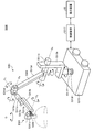
- FIG. 1 is a diagram illustrating an example of a schematic configuration of a microsurgery system to which the technology according to the present disclosure can be applied. It is a figure showing a situation of operation using a microscope operation system. It is a figure which shows an example of the control state which holds a zoom frame in the center part of a screen with which a microscope operation system is provided.
- FIG. 1 is a diagram illustrating an example of a schematic configuration of an endoscopic surgery system 5000 to which a medical observation system according to the present disclosure may be applied.
- FIG. 1 shows a state in which an operator (doctor) 5061 performs an operation on a patient 5071 on a patient bed 5069 using the endoscopic surgery system 5000.
- the scopist 5062 grasps the endoscope 5001 and inserts it into the body cavity of the patient 5071.
- the assistant 5063 grasps the surgical instrument 5017 and inserts it into the body cavity of the patient 5071.
- trocars 5025a to 5025d are punctured into the abdominal wall. Then, the lens barrel 5003 of the endoscope 5001 and other surgical tools 5017 are inserted into the body cavity of the patient 5071 from the trocars 5025a to 5025d.
- an insufflation tube 5019, an energy treatment tool 5021, and forceps 5023 are inserted into the body cavity of the patient 5071 as other operation tools 5017.
- the insufflation tube 5019 sends gas into the body cavity to inflate the body cavity of the patient 5071 for the purpose of securing the visual field by the endoscope 5001 and securing the working space of the operator 5061.
- the energy treatment device 5021 is a treatment device that performs incision and exfoliation of tissue, sealing of blood vessels, and the like by using high-frequency current and ultrasonic vibration.
- the insufflation tube 5019 and the energy treatment device 5021 are connected to a control device (not shown), and the operation device 5017 receiving an instruction from the operator 5061 or the like performs a predetermined operation.
- the illustrated surgical tool 5017 is merely an example, and various surgical tools generally used in an endoscopic operation, such as a set and a retractor, may be used as the surgical tool 5017.
- An image of an operation field in the body cavity of the patient 5071 captured by the endoscope 5001 (hereinafter, referred to as an operation field image) is displayed on the display device 50.
- the operator 5061 performs a procedure such as excision of an affected part using the energy treatment tool 5021 and the forceps 5023 while viewing the operation field image displayed on the display device 50 in real time.
- the scopist 5062 adjusts the position of the endoscope 5001 so that the affected area is displayed in the operative field image while viewing the operative field image displayed on the display device 50 in real time.
- the insufflation tube 5019, the energy treatment tool 5021, and the forceps 5023 are gripped by an operator 5061, an assistant 5063, and the like during the operation.
- the endoscope 5001 includes a lens barrel 5003 (also referred to as a scope) in which a region of a predetermined length from the distal end is inserted into a body cavity of the patient 5071, and a camera head 5005 connected to a proximal end of the lens barrel 5003. Be composed.
- a lens barrel 5003 also referred to as a scope
- a camera head 5005 connected to a proximal end of the lens barrel 5003.
- An opening in which the objective lens is fitted is provided at the tip of the lens barrel 5003.
- a light source device (not shown) is connected to the endoscope 5001, and light generated by the light source device is guided to the distal end of the lens barrel 5003 by a light guide extending inside the lens barrel 5003. Irradiation is performed toward an observation target in a body cavity of the patient 5071 through an objective lens.
- the endoscope 5001 may be a direct view, a perspective view, or a side view.
- An optical system and an image sensor are provided inside the camera head 5005, and the reflected light (observation light) from the observation target is focused on the image sensor by the optical system.
- the observation light is photoelectrically converted by the imaging element, and an electric signal corresponding to the observation light, that is, an image signal corresponding to the observation image is generated.
- the image signal is transmitted as raw data to a camera control unit (CCU) 12a.
- the camera head 5005 has a function of adjusting the magnification and the focal length by appropriately driving the optical system.
- the camera head 5005 may be provided with a plurality of image pickup devices.
- a plurality of relay optical systems are provided inside the lens barrel 5003 to guide observation light to each of the plurality of imaging elements.
- the endoscopic surgery system 5000 includes an input device that receives various information inputs and instruction inputs from a surgeon 5061, a scopist 5062, or an assistant 5063, which is a user.
- the user inputs various kinds of information related to surgery, such as patient's physical information and information about a surgical procedure, via an input device.
- the user drives the operation tool 5017 such as the energy treatment tool 5021 or the like via the input device, by instructing to change the imaging conditions (the type of irradiation light, the magnification, the focal length, and the like) by the endoscope 5001.
- the user inputs an instruction or the like that the user is to be made.
- the type of the input device is not limited, and the input device may be various known input devices.
- the input device for example, a mouse, a keyboard, a touch panel, a switch, and / or a lever can be applied.
- FIG. 1 shows an example in which a scopist 5062 inputs information using a foot switch 5057 which is an example of an input device.
- the scopist 5062 sets a region of interest in the operative field image via the foot switch 5057, and the like. Details will be described later.
- the touch panel may be provided on the display surface of the display device 50.
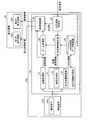
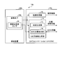
- FIG. 2 is a functional block diagram showing a functional configuration of the medical observation system 10a applied to the endoscopic operation.
- the medical observation system 10a is a system that is applied to, for example, the above-described endoscopic surgery system 5000 and monitors an operation field image using an endoscope 5001 inserted into a body cavity of a patient 5071 during a surgery.
- the medical observation system 10a is a system that displays an enlarged operation field image in which a set attention area is always enlarged based on the three-dimensional position of the operation field, regardless of the position and orientation of the endoscope 5001. .
- the medical observation system 10a includes an imaging device 42a and a camera control unit 12a.
- the imaging device 42a is mounted on the camera head 5005 of the endoscope 5001 and captures an operation field in a body cavity of the patient 5071 to obtain an operation field image.
- the camera control unit 12a generates an operation field image and generates three-dimensional information of the operation field when the imaging device 42a performs imaging.
- the imaging device 42a includes an imaging element 44a.
- the imaging element 44a is configured by an imaging element (photoelectric conversion element) such as a CMOS (Complementary Metal Oxide Semiconductor) image sensor or a CCD (Charge Coupled Device) image sensor, and converts light from an operation field into an electric signal. .
- CMOS Complementary Metal Oxide Semiconductor
- CCD Charge Coupled Device
- the camera control unit 12a includes a three-dimensional information generation unit 14, a development processing unit 18, an attention area setting unit 20, an attention area estimation unit 22, a three-dimensional map data storage unit 24, a zoom processing unit 26, And a control unit 40.
- the camera control unit 12a always generates an enlarged operation field image in which the region of interest is enlarged irrespective of the position and orientation of the endoscope, and causes the display device 50 to display the image.
- the camera control unit 12a is an example of the medical observation device according to the present disclosure.
- the three-dimensional information generation unit 14 calculates a three-dimensional position of, for example, an operation field image in a body cavity captured by the imaging element 44a.
- the three-dimensional information generator 14 includes a map generator 15 and a self-position estimator 16.
- the map generation unit 15 generates a three-dimensional map (hereinafter, simply referred to as a map) indicating a three-dimensional position of an operation field and a three-dimensional position of a region of interest described below. A method for generating a map will be described later.
- the self-position estimating unit 16 estimates the self-position and posture of the endoscope 5001 at the predetermined timing based on the generated map and the operation field image captured at a predetermined timing.
- the development processing unit 18 performs a development process for converting the imaging data into a viewable image.
- the development processing unit 18 performs various types of image processing for displaying an image, such as a development process (demosaicing process), on the RAW data output from the image sensor 44a. More specifically, the development processing unit 18 converts the RAW data into visible image data by applying a preset digital gain or gamma curve to the RAW data. It is desirable that the digital gain and the gamma curve to be set are adjusted in advance so that image data that is easy for the operator 5061 and the scopist 5062 to see is generated.
- the attention area setting unit 20 designates, for example, an area of interest, such as a tumor to be removed by surgery, from an operative field image captured by the imaging element 44a and converted to be visible by the development processing unit 18. More specifically, the operator of the medical observation system 10a sets at least one region of interest from the operative field image while monitoring the operative field image on the display device 50 such as a liquid crystal monitor. A specific method of setting the attention area will be described later. Note that the attention area setting unit 20 is an example of a setting unit according to the present disclosure.
- the attention area estimation unit 22 estimates the position of the attention area in the surgical field image at an arbitrary timing. Note that the attention area estimation unit 22 is an example of an estimation unit in the present disclosure.
- the three-dimensional map data storage unit 24 stores the three-dimensional map of the surgical field generated by the map generation unit 15 described above. Note that the three-dimensional map stored in the three-dimensional map data storage unit 24 is updated over time.
- the zoom processing unit 26 generates an enlarged operation field image obtained by enlarging the attention area estimated at the timing based on the position of the attention area estimated by the attention area estimation unit 22.
- the zoom processing unit 26 is an example of an enlarged image generation unit according to the present disclosure.
- the zoom processing unit 26 performs electronic zoom processing on the operative field image by, for example, interpolating pixel values between pixels. Interpolation of the pixel values may be performed using a known method such as the nearest neighbor method, the bilinear method, the bicubic method, and the Lanczos method. Further, the zoom processing unit 26 may perform the electronic zoom by performing the super-resolution processing.
- the zoom magnification may be a predetermined magnification set in advance, or may be automatically determined by the zoom processing unit 26 from the size of the attention area. Further, a user such as a scopist 5062 who is an operator may specify the magnification.
- the display control unit 40 performs display control to output the operation field image generated by the development processing unit 18 and the enlarged operation field image generated by the zoom processing unit 26 to the display device 50.
- the display device 50 various known display devices such as a liquid crystal display device or an EL (Electro Luminescence) display device can be applied.
- the display device 50 includes at least a first display area 52a for displaying an enlarged operation field image. Further, as shown in FIG. 2, the display device 50 may include a second display area 52b for displaying an operation field image, in addition to the first display area 52a.
- the display device 50 may include a first display region 52a and a second display region 52b in one monitor, or the display device 50 is configured by two different monitors, and The monitors may each include a first display area 52a and a second display area 52b.
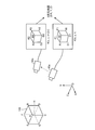
- FIG. 3 is a diagram illustrating a method in which the map generation unit 15 generates a three-dimensional map of an operation field.
- FIG. 3 illustrates a state in which the imaging device 42a observes the stationary object 100 in the three-dimensional space XYZ in which a point on the space is set as the reference position O. Then, the imaging device 42a captures the operation field image K (x, y, t) at a predetermined timing, for example, time t, and at a timing different from the predetermined timing, for example, time t + ⁇ t. , Y, t + ⁇ t). Note that the time interval ⁇ t is set to, for example, 33 msec.
- the reference position O may be set arbitrarily, but is desirably set, for example, to a position that does not move with time. Note that x in the surgical field image K (x, y, t) represents the horizontal coordinate of the image, and y represents the vertical coordinate of the image.
- the map generation unit 15 detects a feature point, which is a pixel serving as a feature, from the operative field image K (x, y, t) and the operative field image K (x, y, t + ⁇ t).
- the feature point is, for example, a pixel whose pixel value differs from an adjacent pixel by a predetermined value or more. Note that it is desirable that the feature points are points that exist stably even after a lapse of time. For example, pixels forming edges in an image are often used.
- feature points A1, B1, C1, D1, E1, F1, and H1, which are vertices of the object 100 are detected from the operative field image K (x, y, t). Suppose it was done.
- the map generation unit 15 searches the surgical field image K (x, y, t + ⁇ t) for points respectively corresponding to the feature points A1, B1, C1, D1, E1, F1, and H1. Specifically, based on the pixel value of the feature point A1, the pixel value near the feature point A1, and the like, a point having the same feature is searched for in the surgical field image K (x, y, t + ⁇ t). By this search processing, feature points A2, B2, C2, D2, E2 corresponding to feature points A1, B1, C1, D1, E1, F1, and H1 from the surgical field image K (x, y, t + ⁇ t). It is assumed that F2 and H2 are respectively detected.
- the map generation unit 15 for example, two-dimensional coordinates of the feature point A1 on the operative field image K (x, y, t + ⁇ t) and the operative field image K of the feature point A2 From the two-dimensional coordinates on (x, y, t + ⁇ t), the three-dimensional coordinates (X A , Y A , Z A ) of the point A in space are calculated. As a set of the three-dimensional coordinates (X A , Y A , Z A ) calculated in this way, a three-dimensional map D (X, Y, Z) of the space where the object 100 is placed is generated. The generated three-dimensional map D (X, Y, Z) is stored in the three-dimensional map data storage unit 24. Note that the three-dimensional map D (X, Y, Z) is an example of three-dimensional information in the present disclosure.
- the map generation unit 15 also estimates the position and orientation of the imaging device 42a at the same time.
- the operative field image K (x, y, t) and the operative field image K (x) are set as unknowns with the three-dimensional coordinates of each feature point constituting the object 100, the position and the posture of the imaging device 42a as unknowns.
- Y, t + ⁇ t a simultaneous equation is established based on the two-dimensional coordinates of the feature points respectively observed.
- the map generating unit 15 estimates the three-dimensional coordinates of each feature point constituting the object 100 and the position and orientation of the imaging device 42a by solving the simultaneous equations.
- a plurality of feature points are detected from the operative field image K (x, y, t) captured by the imaging device 42a, and those feature points are detected from the operative field image K (x, y, t + ⁇ t).
- a point corresponding to the feature point a three-dimensional map D (X, Y, Z) of the environment observed by the imaging device 42a can be generated.
- the position and orientation of the imaging device 42a that is, the self-position can be estimated.
- a feature point that was initially invisible becomes visible, so that the three-dimensional map D (X, Y, Z) can be expanded.
- the three-dimensional position of the same feature point can be repeatedly calculated. For example, by performing averaging processing, a calculation error can be reduced.
- the three-dimensional map D (X, Y, Z) stored in the three-dimensional map data storage unit 24 is updated as needed.
- the technique for creating a three-dimensional map of the environment and specifying the self-position of the imaging device 42a is generally called SLAM (Simultaneous Localization and Mapping) technology.
- the basic principle of SLAM technology using a monocular camera is described in, for example, "Andrew J. Davison," Real-Time Simultaneous Localization and Mapping with with a Single Camera "," Proceedings of the 9th IEEE IEEE International Conference on Computer Vision Volume 2, 2003. pp. 1403-1410 ".
- the SLAM technique for estimating the three-dimensional position of a subject using a camera image of the subject is also called Visual @ SLAM.
- the attention area is set by the operation of the attention area setting unit 20. Specifically, the attention area setting unit 20 superimposes and displays an attention frame indicating the attention area on the surgical field image, and specifies the size, shape, and position of the attention frame.
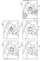
- FIG. 4 is a diagram showing an example of a method of setting a frame of interest.
- FIG. 4A is a diagram showing an example of an operation field image K (x, y) observed by the endoscope 5001.
- the information of the timing (for example, time) at which the operative field image was captured is omitted, and the operative field image is simply described as K (x, y).
- FIG. 4B shows an example in which the orientation of the endoscope 5001 is adjusted so that the affected area to be set as the attention area is displayed in the center of the surgical field image K (x, y), and the attention area setting unit 20 sets the attention area indicating the attention area.
- FIG. 3 is a diagram illustrating an example of a state in which a frame 110 is set.
- FIG. 4C is a diagram illustrating an example of an enlarged operative field image L (x, y) in which an area including the attention frame 110 is enlarged and displayed at a predetermined magnification.
- the scopist 5062 sets the specific position to be enlarged such as the affected part at the center (an example of a predetermined position) of the operation field image K (x, y).
- the endoscope 5001 is moved so as to be reflected.
- the scopist 5062 depresses the foot switch 5057 (FIG. 1) and The region setting unit 20 is instructed to set the region of interest.
- the setting signal instructing the setting of the attention area is generated with the stepping on of the foot switch 5057 as a trigger.
- the attention area setting unit 20 places an attention frame 110 of a predetermined size in the center of the surgical field image K (x, y), as shown in FIG. 4B. By displaying, the attention area is set.
- the size and shape of the attention frame 110 may be set arbitrarily, but will be described later in detail.
- the method of setting the attention area by the attention area setting unit 20 is not limited to the above-described method.
- a touch panel may be provided by being stacked on the screen of the display device 50, and by detecting an operation of the touch panel, the attention area may be set at a position where the touch panel is pressed. Further, the position and shape of the attention area may be set by a mouse. Furthermore, the attention area setting unit 20 may set the position and shape of the attention area based on an operation such as a gesture.
- FIG. 5 is a diagram showing another example of a method of setting the attention frame.
- FIG. 5A is a diagram showing an example of an operation field image K (x, y) observed by the endoscope 5001. While viewing the operation field image K (x, y) displayed on the display device 50, the scopist 5062 specifies the position of the region of interest using an input device such as a touch panel or a mouse.
- the attention area setting unit 20 displays the attention area instruction information 105 indicating the designated area by superimposing the attention area image K (x, y).
- the attention area setting unit 20 sets the attention frame 110 at the position of the input attention area instruction information 105.
- the attention area setting unit 20 displays the set attention frame 110 as shown in FIG. 5B so as to be superimposed on the operation field image K (x, y).
- the attention frame 110 may be a frame of a preset size and shape, or may be a closed region imitating the attention region instruction information 105.
- the zoom processing unit 26 enlarges the set attention frame 110 at a predetermined magnification, as shown in FIG. 5C, at the enlarged operation field image L (x, y). Is generated and displayed.
- the attention area setting unit 20 uses the three-dimensional map D (X, Y, Z) to take into account conditions such as a distance in a three-dimensional space and a distance from an imaging system within a certain range. To set the attention area.
- the display form of the attention frame 110 is not limited to those shown in FIGS. Variations of the display form of the attention frame 110 will be described later (see FIG. 18).
- the attention area setting unit 20 may set the position and shape of the attention area based on an operation such as a gesture.
- the zoom processing unit 26 enlarges an area including the attention frame 110 of the operation field image K (x, y) at a predetermined magnification, and enlarges the operation field image L (x, y). Generate At this time, as shown in FIG. 4C, the attention frame 110 is also enlarged and displayed at a predetermined magnification. Then, the display control unit 40 outputs the generated enlarged operative field image L (x, y) to the display device 50 and displays it. The surgeon 5061 performs an operation while observing the enlarged operation field image L (x, y) displayed on the display device 50.
- the medical observation system 10a captures the operation field image K (x, y) at a predetermined time interval ⁇ t. Is repeated. Then, each time the operation field image K (x, y) is captured, generation and display of a new enlarged operation field image L (x, y) are repeated.
- the attention area estimation unit 22 estimates the location of the attention area from the operative field image K (x, y).
- the zoom processing unit 26 generates an enlarged operation field image L (x, y) in which the estimated attention area is enlarged at a predetermined magnification.
- the display control unit 40 outputs the enlarged operative field image L (x, y) to the display device 50 to be displayed, as shown in FIG. 4C.
- the medical observation system 10a continues to display the enlarged operative field image L (x, y) on the display device 50.
- the attention area estimation unit 22 estimates the location of the attention area from the operative field image K (x, y) when the position or orientation of the endoscope 5001 changes.
- the attention area estimation unit 22 determines the position and orientation of the endoscope 5001 at a predetermined timing, for example, time t, the timing and the position of the endoscope 5001 at a time different from the predetermined timing, for example, time t + ⁇ t, Based on the map D (X, Y, Z), it is estimated at which position of the attention frame 110 at time t in the surgical field image K (x, y, t + ⁇ t) at time t + ⁇ t. .
- the attention area estimation unit 22 determines how the plurality of feature points near the set attention frame 110 move between time t and time t + ⁇ t. Identify what you have done. Then, the attention area estimation unit 22 estimates the position of the attention area based on the movement state of the specified feature point.
- the region set as the region of interest is generally an affected part to be operated.
- the affected area is likely to be resected, bleeding, or significantly deformed by surgery. Therefore, even if a feature point is set inside the attention area, the feature point may disappear with the passage of time. Therefore, it is desirable to extract a feature point from an area excluding the periphery of the attention area from the operative field image K (x, y) after the attention area is set.
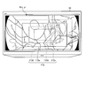
- FIG. 6 is an image showing an example in which a region for extracting a feature point is set.
- the map generation unit 15 sets the mask 120 around the screen, avoiding the center of the screen where the attention frame 110 is set, as shown in FIG. Then, the map generation unit 15 extracts a feature point only inside the set mask 120. Since the set area of the mask 120 is apart from the attention frame 110 indicating the position of the attention area, it is assumed that the deformation during the operation is small. Therefore, the feature points can be stably detected inside the mask 120 regardless of the passage of time. Since the feature points can be stably extracted, the stability of the estimation accuracy of the three-dimensional map D (X, Y, Z) and the position and orientation of the endoscope 5001 is improved.
- the map generation unit 15 may have a function of removing a previously registered object such as a surgical instrument or a finger from the operative field image K (x, y). This removal function is, for example, a function of recognizing an image of a previously registered object and excluding a region where the recognized object exists from being calculated.
- FIG. 7 is a diagram illustrating an example of an image displayed by the medical observation system 10a.
- the display control unit 40 outputs the operative field image K (x, y) monitored by the scopist 5062 to the display device 50a (the second display area 52b) and displays it.
- the display control unit 40 outputs the enlarged operation field image L (x, y) monitored by the operator 5061 to a display device 50b (first display area 52a) different from the display device 50a and displays the same.
- the surgeon 5061 and the scopist 5062 can arrange the display devices 50a and 50b at positions that are easy to see. Therefore, the surgeon 5061 can facilitate the operation while observing the enlarged operation field image L (x, y). Further, the scopist 5062 can easily adjust the position of the endoscope 5001 while observing the operation field image K (x, y).
- the above-mentioned attention frame 110 and a zoom frame 112 indicating the range of the enlarged operation field image L (x, y) are displayed. You may.
- the attention frame 110 and the zoom frame 112 move in the operation field image K (x, y) according to the movement of the endoscope 5001.
- the scopist 5062 checks only the operation field image K (x, y) and performs the enlargement operation. It is possible to immediately confirm whether an appropriate range is displayed in the field image L (x, y). If it is not necessary to display the attention frame 110 and the zoom frame 112, these displays may be turned on / off independently by an operation instruction of the scopist 5062.
- the medical observation system 10a generates the three-dimensional map D (X, Y, Z) and estimates the position and orientation of the endoscope 5001, so that the three-dimensional position of a feature point near the attention area is determined. Can be calculated. Therefore, by performing perspective transformation and / or rotation transformation of the captured operation field image K (x, y), an enlarged operation field image L (x, y) in which the attention area is always viewed from the same direction is generated and displayed. It can also be done.
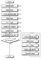
- FIG. 7 is a flowchart illustrating an example of the flow of a process performed by the medical observation system 10a.
- the imaging element 44a captures an operation field image K (x, y) (Step S10).
- the map generation unit 15 extracts a feature point from the captured surgical field image K (x, y) (step S11).
- the imaging element 44a captures an operation field image K (x, y) at a predetermined timing, for example, ⁇ t seconds later (step S12).
- the map generation unit 15 extracts a feature point from the captured operative field image K (x, y) after ⁇ t seconds (step S13).
- the map generation unit 15 generates a three-dimensional map D (X, Y, Z) by calculating a three-dimensional position of a feature point (step S14).
- the self-position estimating unit 16 estimates the position and orientation of the endoscope 5001 (Step S15).
- the attention area setting unit 20 sets an attention area in the operative field image K (x, y) (step S16).
- the zoom processing unit 26 generates the enlarged operation field image L (x, y). Then, the display control unit 40 causes the display device 50 to display the generated enlarged operative field image L (x, y) (Step S17).
- the display control unit 40 determines whether there is an instruction to end the process (Step S18). If it is determined that there is an end instruction (step S18: Yes), the medical observation system 10a ends the processing in FIG. On the other hand, if it is not determined that there is an end instruction (step S18: No), the process proceeds to step S19.
- the instruction to end the process is performed by detecting an operation such as turning off a power switch (not shown) of the camera control unit 12a.
- step S18 the imaging element 44a captures an operation field image K (x, y) at a predetermined timing, for example, ⁇ t seconds later (step S19).
- the map generation unit 15 extracts a feature point from the photographed surgical field image K (x, y) after ⁇ t seconds (step S20).
- the map generation unit 15 updates the three-dimensional map D (X, Y, Z) generated in step S14 by calculating the three-dimensional position of the feature point (step S21).
- the self-position estimating unit 16 estimates the position and orientation of the endoscope 5001 (Step S22).
- the attention area estimation unit 22 estimates the position of the attention area in the surgical field image K (x, y) after ⁇ t seconds captured in step S19 (step S23). Thereafter, the process returns to step S17.
- the three-dimensional information generation unit 14 converts the three-dimensional information of the surgical field from the surgical field image K (x, y) captured by the imaging device 42a.
- a dimensional map D (X, Y, Z) (three-dimensional information) is generated.
- the attention area setting section 20 sets at least one attention area in the surgical field image K (x, y) captured at a predetermined timing.
- the attention area estimation unit 22 (estimation unit) performs imaging at a timing different from the predetermined timing based on the three-dimensional map D (X, Y, Z) and the position of the attention area set by the attention area setting unit 20.
- the existence position of the attention area is estimated from the obtained operation field image K (x, y). Then, the zoom processing unit 26 (enlarged image generation unit) generates an enlarged operation field image L (x, y) in which the estimated attention area is enlarged at a predetermined magnification, and the display control unit 40 performs at least the enlargement operation. A field image L (x, y) is output. Therefore, even when the endoscope 5001 on which the imaging device 42a is mounted changes its position or posture, it is possible to continue observing the diseased part in an enlarged manner from a remote position.
- the display control unit 40 displays the operative field image K (x, y) and the enlarged operative field image L (x, y). Therefore, both the enlarged operation field image L (x, y) that the operator 5061 wants to see and the operation field image K (x, y) that the scopist 5062 wants to see can be displayed.
- the display control unit 40 controls the two display devices 50a and 50b to display the operative field image K (x, y) and the enlarged operative field image L ( x, y). Therefore, the surgeon 5061 and the scopist 5062 can arrange the display devices 50a and 50b at positions that are easy to see.
- the attention area setting unit 20 sets the operation field image K (x, y) displayed on the display device 50 by the display control unit 40.
- the specific position is designated as the region of interest on condition that a setting signal instructing the setting of the region of interest is generated in a state where the specific position matches the predetermined position of the display device 50. Therefore, the attention area can be set easily and surely by the routine operation.
- the attention area setting unit 20 sets the operation area image K (x, y) displayed on the display device 50 by the display control unit 40. At the position specified by the input device. Therefore, the attention area can be easily and reliably set by an intuitive operation.
- the imaging device 42a includes one imaging element 44a, and the three-dimensional information generation unit 14 determines at least two images captured by the imaging device 42a at different times.
- a three-dimensional map D (X, Y, Z) (three-dimensional information) of the operative field is generated based on the operative field images K (x, y). Therefore, using the imaging device 42a having a simple configuration including only the single-lens camera, the affected part can be continuously observed while being enlarged from a distant position.
- the imaging device 42a is mounted on the endoscope 5001. Therefore, when performing an operation or the like using the endoscope 5001, the operator 5061 can enlarge the affected part and observe it stably.
- the three-dimensional information generating unit 14 converts the three-dimensional information of the surgical field from the surgical field image K (x, y) obtained by capturing the surgical field.
- a map D (X, Y, Z) (three-dimensional information) is generated.
- the attention area setting unit 20 sets at least one attention area in the operative field image K (x, y) captured at a certain time.
- the attention area estimation unit 22 (estimation unit) is imaged at a time different from the time based on the three-dimensional map D (X, Y, Z) and the position of the attention area set by the attention area setting unit 20.
- the zoom processing unit 26 (enlarged image generation unit) generates an enlarged operation field image L (x, y) obtained by enlarging the estimated attention area at a predetermined magnification, and the display control unit 40 performs at least the enlargement operation.
- the field image L (x, y) is displayed. Therefore, the affected part can be continuously observed while being enlarged.
- the endoscope 5001 including the imaging device 42a may include an acceleration sensor such as a gyro sensor.
- an acceleration sensor such as a gyro sensor.
- the position and orientation of the endoscope 5001 can be measured in real time. Therefore, the position and orientation of the endoscope 5001 can be measured without the imaging device 42a capturing two images at different times, and thereby, the position of the attention area can be estimated.
- the configuration of the medical observation system 10a is not limited to the configuration described in the first embodiment, and various modifications can be realized.
- another embodiment of the medical observation system will be described step by step.
- FIG. 9 is a diagram illustrating an example of a display mode of an image output from the display control unit 40 to the display device 50. That is, in the first embodiment, the display control unit 40 outputs only the enlarged operative field image L (x, y) to the display device 50, and the display device 50 displays the operative field image K on different display devices 50a and 50b. An example in which (x, y) and the enlarged operation field image L (x, y) are output has been described, but the display form of the output image is not limited thereto.
- 9A is an example in which the display control unit 40 causes the display device 50 to display the operation field image K (x, y) and the enlarged operation field image L (x, y) adjacent to each other (side-by-side). That is, the enlarged operation field image L (x, y) is displayed on the first display area 52a set on the display screen of the display device 50, and the operation field image K (x, y) is displayed on the second display area 52b. Is displayed.
- the operator 5061 can proceed with the surgery while observing the enlarged operation field image L (x, y), and the scopist 5062 can perform the operation field image K (x, y).
- the position of the endoscope 5001 can be adjusted.
- FIG. 9B shows an example in which the display control unit 40 superimposes (in PinP) an operation field image K (x, y) on a part of the enlarged operation field image L (x, y) and displays the image on the display device 50. It is. In this case, the second display area 52b is superimposed on a part of the first display area 52a.
- the operator 5061 can proceed with the surgery while observing the enlarged operation field image L (x, y), and the scopist 5062 can perform the operation field image K (x, y).
- the position of the endoscope 5001 can be adjusted.
- the position at which the operation field image K (x, y) is superimposed is not limited to the example of FIG. 9B, and may be any of the upper left, upper right, and lower right positions of the enlarged operation field image L (x, y). May be superimposed.
- the display control unit 40 displays the operative field image K (x, y) and the enlarged operative field image L (x, y) on one display device 50 adjacent to each other. And display it. Therefore, both the enlarged operation field image L (x, y) that the operator 5061 wants to see and the operation field image K (x, y) that the scopist 5062 wants to see can be displayed.
- the display control unit 40 superimposes the operation field image K (x, y) on a part of the enlarged operation field image L (x, y) on one display device 50. To display. Therefore, both the enlarged operation field image L (x, y) that the operator 5061 wants to see and the operation field image K (x, y) that the scopist 5062 wants to see can be displayed. In particular, the enlarged operation field image L (x, y) can be displayed as large as possible.
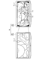
- FIG. 10 is a diagram illustrating an example of a process performed when the zoom frame reaches an end of the operation field image K (x, y) as the endoscope 5001 moves.
- the zoom frame is a frame indicating a display range of the enlarged operative field image L (x, y).
- the surgical field image K (x, y) observed by the endoscope 5001 has a circular shading area 130 around it. Since the shading area 130 is an area where light does not reach, it is observed as a black area as shown in FIG. 10A.
- the zoom frame may reach the end of the operation field image K (x, y).
- the medical observation system 10a takes one of the three processing modes prepared in advance.
- FIG. 10B is an example in which, when the zoom frame 112a reaches the end of the operative field image K (x, y), an area without image information is displayed in black. That is, the zoom processing unit 26 sets a predetermined pixel value (for example, a black pixel) in an area of the zoom frame 112a that exceeds the edge of the surgical field image K (x, y) and an area that overlaps the shaded area 130. An enlarged operative field image L (x, y) that stores the pixel value 0) is generated. Then, the display control unit 40 displays the generated enlarged operation field image L (x, y).
- a predetermined pixel value for example, a black pixel
- the zoom frame 112a reaches the position shown in FIG. 10A
- the enlarged surgical field image L ( (x, y) is displayed.
- the scopist 5062 immediately recognizes that the position of the endoscope 5001 has reached the end of the operation field image K (x, y) since the black region is enlarged. be able to. Then, by adjusting the position of the endoscope 5001, the scopist 5062 can regenerate the enlarged operative field image L (x, y).
- FIG. 10C is an example in which, when the zoom frame 112a reaches the end of the operation field image K (x, y), the screen end is kept displayed as it is. That is, the zoom processing unit 26 determines that the edge of the zoom frame 112a, that is, the edge of the enlarged operative field image L (x, y) matches the edge of the operative field image K (x, y). Even if the endoscope 5001 further moves beyond the edge of the operation field image K (x, y), the position of the zoom frame 112a is maintained and the enlarged operation field image L (x, y) is maintained. Generate Then, the display control unit 40 displays the generated enlarged operation field image L (x, y).
- the zoom frame 112a when the zoom frame 112a reaches the position shown in FIG. 10A, the zoom frame 112a is moved to the position of the zoom frame 112b, and the image inside the moved zoom frame 112b is enlarged. (X, y). That is, at this time, the left end of the zoom frame 112b matches the left end of the operation field image K (x, y). With this display mode, the display area of the enlarged operative field image L (x, y) is held at the end of the operative field image K (x, y) regardless of the movement of the endoscope 5001. be able to.
- FIG. 10D is an example in which the zoom processing unit 26 stops generating the enlarged operative field image L (x, y) when the zoom frame 112a reaches the end of the operative field image K (x, y). Then, at this time, the display control unit 40 displays the operation field image K (x, y).
- the display of the enlarged operative field image L (x, y) is released by the scopist 5062, so that the imaging range of the endoscope 5001 is changed to the operative field image K (x, y).
- the end can be immediately recognized.
- the scopist 5062 can regenerate the enlarged operative field image L (x, y).
- the zoom processing unit 26 determines whether the zoom frame 112a has reached the edge of the operative field image K (x, y), or When the image K (x, y) overlaps with the shaded area, the enlarged operation field storing a predetermined pixel value is stored in the area of the zoom frame 112a that exceeds the edge and overlaps with the shaded area. Generate an image L (x, y). Therefore, the scopist 5062 can immediately recognize that the zoom frame 112a has reached the edge of the operation field image K (x, y). Then, the scopist 5062 can adjust the position of the endoscope 5001 so that the scoring does not occur.
- the zoom processing unit 26 (enlarged image generation unit) An enlarged operative field image L (x, y) in which the edge of L (x, y) matches the edge of the operative field image K (x, y) is generated. Therefore, it is possible to continue to display the enlarged surgical field image L (x, y) without any shading.
- the zoom processing unit 26 determines whether the zoom frame 112a has reached the edge of the operative field image K (x, y) or the operative field image K If the area overlaps the (x, y) shaded area, the generation of the enlarged operative field image L (x, y) is stopped. Therefore, the scopist 5062 can immediately recognize that the imaging range of the endoscope 5001 has reached the end of the operation field image K (x, y). Then, the scopist 5062 can adjust the position of the endoscope 5001 so that the scoring does not occur.
- the medical observation system 10a has been described assuming that the imaging device 42a has one imaging element 44a.
- the configuration of the imaging device is not limited to this.
- FIG. 11 is a diagram illustrating an example of a schematic configuration of a medical observation system 10b in which the imaging device 42b includes an imaging element 44b including an image plane phase difference sensor 46.
- FIG. 11 FIG. 2 is partially omitted, and unless otherwise noted, the omitted portions have the same configuration as FIG.
- the image plane phase difference sensor 46 has a configuration in which pixels for distance measurement are discretely arranged in the image sensor 44b.
- the map generation unit 15 uses the image plane phase difference information output from the image plane phase difference sensor 46 to obtain depth information (distance) to the imaged object 100. Information). Therefore, the SLAM technology can be effectively used.
- the image plane phase difference sensor 46 can obtain depth information from only one captured image.
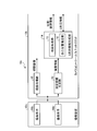
- FIG. 12 is a diagram illustrating an example of a schematic configuration of a medical observation system 10c in which the imaging device 42c includes two imaging elements 44c and 44d.
- the two image sensors 44c and 44d are arranged in a state where a predetermined relative relationship is maintained, and image different places of the affected part so as to partially overlap. More specifically, the imaging elements 44c and 44d respectively acquire right-eye and left-eye image signals corresponding to stereoscopic vision.
- FIG. 2 is partially omitted, and unless otherwise specified, the omitted portions have the same configuration as FIG.
- the camera control unit 12b includes a depth information generation unit 30 in addition to the configuration described with reference to FIG.
- the depth information generation unit 30 generates depth information by performing matching between two operation field images captured by the two imaging elements 44c and 44d, respectively.
- the map generation unit 15 uses the depth information generated by the depth information generation unit 30 and the operation field images captured by the imaging elements 44c and 44d, respectively.
- the three-dimensional map D (X, Y, Z) can be generated by utilizing the SLAM technology.
- the two imaging elements 44c and 44d can perform imaging simultaneously, depth information can be obtained from two images obtained by one imaging. Therefore, even when the object is moving, the three-dimensional position of the object can be measured with high accuracy.
- the imaging device 42c includes the two imaging elements 44c and 44d that capture images in different ranges where a part of the imaging device 42c overlaps, and the three-dimensional information generation unit 14 performs two imaging operations.
- the elements 44c and 44d generate three-dimensional information of the operation field based on the two operation field images K (x, y) captured at the same time. Therefore, since depth information can be obtained from two operation field images K (x, y) obtained by one imaging, even when the operation field is moving, the three-dimensional position of the operation field can be obtained. Can be measured with high accuracy.
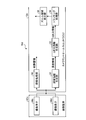
- FIG. 13 is a diagram illustrating an example of a schematic configuration of a medical observation system 10d in which the imaging device 42c includes two imaging elements and the camera control unit 12c includes the tracking processing unit 34. Note that FIG. 13 partially illustrates FIG. 2 and omits parts having the same configuration as FIG. 2 unless otherwise specified.
- the camera control unit 12c of the medical observation system 10d includes a depth information generation unit 30, a three-dimensional information generation unit 32, a tracking processing unit 34, and a zoom area calculation unit 36.
- the three-dimensional information generation unit 32 is provided in place of the three-dimensional information generation unit 14 (FIG. 2), and based on the depth information generated by the depth information generation unit 30, the three-dimensional information K (x, y) Generate dimensional information.
- the tracking processing unit 34 is provided in place of the three-dimensional map data storage unit 24 (FIG. 2), and superimposes two point groups based on the three-dimensional information of the immediately preceding frame and the three-dimensional information of the current frame.
- the difference between the position and orientation of the imaging device 42c is calculated by using the ICP (Iterative @ Closest @ Point) method or the like.
- the zoom area calculation unit 36 is provided in place of the attention area estimation unit 22 (FIG.
- the zoom area calculation unit 36 displays the attention area on the screen. Calculate the coordinates. Then, the above-described zoom processing unit 26 (FIG. 2) performs a zoom process on the region calculated by the zoom region calculation unit 36, and generates an enlarged operation field image L (x, y).
- the attention area in the surgical field image K (x, y) can be stably tracked without depending on the movement of the imaging device 42c.
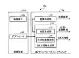
- FIG. 14 is a diagram illustrating an example of a schematic configuration of a medical observation system 10e in which the imaging device 42d includes the imaging element 44a and the depth sensor 48.
- FIG. 2 is partially omitted, and unless otherwise specified, the omitted portions have the same configuration as FIG.
- the ⁇ depth sensor 48 is a so-called 3D sensor that measures the distance to the subject.
- the depth sensor 48 is a so-called ToF (Time @ of @ Flight) sensor that measures the flight time of light and measures the distance to the object by receiving reflected light, such as infrared light, radiated toward the object. is there.
- the depth sensor 48 is realized by a so-called pattern projection method (Structured @ Light) that measures the distance to the subject by capturing images of projection light having a plurality of different geometric patterns applied to the subject.
- the map generation unit 15 extracts depth information (distance information) up to the imaged object 100 based on the operation field image K (x, y) captured by the imaging element 44a and the distance output by the depth sensor 48. More specifically, the map generation unit 15 calculates which pixel of the surgical field image K (x, y) captured by the image sensor 44a corresponds to the point measured by the depth sensor 48. Then, the map generator 15 generates a three-dimensional map D (X, Y, Z) (three-dimensional information) of the surgical field. Therefore, the SLAM technology can be effectively used.
- the imaging device 42d includes the one imaging element 44a and the depth sensor 48 (distance measurement device) that measures the distance to the target, and includes the three-dimensional information generation unit 14 Generates a three-dimensional map D (X, Y, Z) (three-dimensional information) of the operation field based on the image captured by the image sensor 44a and the distance measured by the depth sensor 48. Therefore, the distance to the operation field can be easily and reliably measured.
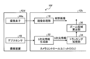
- FIG. 15 is a diagram illustrating an example of a schematic configuration of a medical observation system 10f in which the imaging device 42d includes the imaging element 44a and the depth sensor 48 and the camera control unit 12d includes the tracking processing unit 34.
- FIG. 2 is partially omitted, and unless otherwise specified, the omitted portions have the same configuration as FIG.
- the camera control unit 12d of the medical observation system 10f includes a three-dimensional information generation unit 32, a tracking processing unit 34, and a zoom area calculation unit 36.
- the three-dimensional information generation unit 32 is provided in place of the three-dimensional information generation unit 14 (FIG. 2), and two pieces of distance information measured by the depth sensor 48 from different positions (for example, a pixel value corresponding to the distance to the subject is displayed).
- the moving state of the operation field is obtained by matching the stored distance images.
- the tracking processing unit 34 is provided in place of the three-dimensional map data storage unit 24 (FIG. 2), and calculates a difference between the position and the posture of the imaging device 42c based on the above-described moving state of the operation field.
- the zoom area calculation unit 36 is provided in place of the attention area estimation unit 22 (FIG.
- the zoom area calculation unit 36 displays the attention area on the screen. Calculate the coordinates. Then, the above-described zoom processing unit 26 (FIG. 2) performs a zoom process on the region calculated by the zoom region calculation unit 36, and generates an enlarged operation field image L (x, y).
- the attention area in the surgical field image K (x, y) can be stably tracked without depending on the movement of the imaging device 42d.
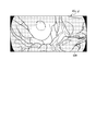
- FIG. 16 is a diagram illustrating an example in which a plurality of attention frames 110a and 110b are set in the operative field image K (x, y).
- the attention area setting unit 20 may set a plurality of attention areas in the surgical field image K (x, y). For example, when it is necessary to pay attention to a plurality of affected areas, the attention area setting unit 20 sets attention frames 110a and 110b indicating each attention area based on the instruction of the scopist 5062. Then, the display control unit 40 causes the display device 50 to display two enlarged operation field images L (x, y) obtained by enlarging the area of the zoom frame corresponding to each of the attention frames 110a and 110b.
- the region of interest setting unit 20 sets a plurality of regions of interest. Therefore, it is possible to display an enlarged operation field image L (x, y) in which a plurality of attention areas are enlarged.
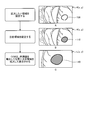
- FIG. 17 is a diagram showing an example in which a region within a predetermined distance range is highlighted from the surgical field image K (x, y).
- the attention area setting unit 20 displays a predetermined distance range area in the operation field image K (x, y) with a predetermined coloring as shown in FIG.
- FIG. 17 is an example in which a region R1 having a distance shorter than the distance d1 and a region R2 having a distance longer than the distance d2 are displayed in different colors. Note that this is a process performed to limit the distance range to the attention area between the distance d1 and the distance d2 in order to facilitate setting of the attention area.
- the values of the distance d1 and the distance d2 are, for example, as shown in FIG. 17, the attention area setting unit 20 displays a distance scale near the operative field image K (x, y), and the scopist 5062
- the setting may be made by operating an input device such as a touch panel. Then, according to the set values of the distance d1 and the distance d2, the attention area setting unit 20 displays the area R1 and the area R2 on the operation field image K (x, y) in real time by coloring. At this time, the operator points the input device at a position of a desired distance on the distance scale to set the distance d1 or the distance d2.
- the attention area setting unit 20 displays a color colored in the dragged distance range on the distance scale as shown in FIG.
- the GUI Graphic User Interface
- the operator can easily recognize a region corresponding to the distance range set by the operator in the operation field image K (x, y).
- the method of displaying the set distance range on the distance scale is not limited to the method shown in FIG. 17, and other display forms may be used as long as the set distance range is clearly indicated. May be taken.
- the display control unit 40 causes the display device 50 to display the operative field image K (x, y) in which the region R1 and the region R2 are displayed in color. Then, the scopist 5062 sets a region of interest according to the above-described procedure (see FIG. 4) while viewing the surgical field image K (x, y) in which the region R1 and the region R2 are displayed in color.
- the attention area setting unit 20 (setting unit) further includes the function of specifying the distance range in which the attention area exists, and the attention area setting unit 20 (setting unit) Set the area. Therefore, the scopist 5062 can more easily set the attention area.
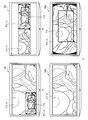
- FIG. 18 is a diagram showing an example of a display form of the attention frames 110c to 110g set in the operation field image K (x, y).
- FIG. 18A is an example in which the attention frame 110c is displayed as a circular area.
- FIG. 18B is an example in which the attention frame 110d is indicated by a colored (highlighted) closed region.
- FIG. 18C is an example in which the attention frame 110e is indicated by a symbol.
- FIG. 18D is an example in which the attention frame 110f is indicated by a closed curve.
- FIG. 18E is an example in which both the attention frame 110g and the area having the same distance as the position where the attention frame 110g is set are colored and displayed.
- the scopist 5062 can recognize that another area exists at a position at the same distance as the attention area. Therefore, the endoscope 5001 can be more carefully grasped so that the tracking of the attention area is not deviated by erroneously turning the endoscope 5001 in the direction of another area.
- the form of the attention frame to be displayed may be set in the attention area setting unit 20 in advance by the scopist 5062.
- the method of setting the attention frames 110c to 110g may follow the method described with reference to FIG. 4 or FIG.
- FIG. 18B, FIG. 18D, and FIG. 18E when the attention frame is set as a closed region of an arbitrary shape, as described with reference to FIG. , Y), it is efficient to directly set the position and shape of the frame of interest.
- the attention frames 110c to 110g in a form that is easy for the operator to see can be displayed in the set attention area.
- FIG. 19 is a diagram illustrating an example of a setting method of the zoom frame 112.
- the scopist 5062 may set a magnification for enlarging the operation field image K (x, y).
- the setting of the magnification is performed, for example, by the zoom processing unit 26 of FIG. 2 instructing the display control unit 40 to superimpose the operation field image K (x, y) on the display device 50 and select a plurality of selectable zoom frames 112. (112c to 112f) may be displayed, and the operator may designate one of the zoom frames.
- FIG. 19 shows an example in which a zoom frame 112e indicating a magnification of 1.5 is specified. Note that the selection of the zoom frame 112 may be performed by, for example, operating an input device such as a switch provided near the endoscope 5001.
- the zoom processing unit 26 may generate the enlarged operative field image L (x, y) at a magnification according to the distance to the attention area. That is, based on the three-dimensional map D (X, Y, Z) generated by the three-dimensional information generation unit 14 and stored in the three-dimensional map data storage unit 24, the zoom processing unit 26 calculates, for example, the distance to the attention area. Is calculated. Then, a magnification for generating the enlarged operative field image L (x, y) is determined according to the calculated distance to the attention area. Also, an AF (Auto Focus) function is implemented in the imaging device 42a, and the imaging device 42a calculates a distance to the attention area by focusing on the position of the attention area estimated by the attention area estimation unit 22. You may. For example, when the distance to the attention area is long, the magnification can be set high, and when the distance to the attention area is short, the magnification can be set low.
- the scopist 5062 easily sets the magnification by selecting one zoom frame from the plurality of zoom frames 112c to 112f displayed on the display device 50. be able to.
- the zoom processing unit 26 (the enlarged image generation unit) generates the enlarged operation field image L (x, y) at a magnification corresponding to the distance to the attention area. Therefore, even when the endoscope 5001 moves in the front-rear direction with respect to the diseased part, the diseased part can be continuously observed at a fixed size.
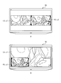
- FIG. 20 is a diagram illustrating an example of a display method of the zoom frame 112 when the medical observation system 10a is operated.
- the zoom processing unit 26 may cause the display control unit 40 to display the zoom frame 112 so as to be superimposed on the operation field image K (x, y) displayed on the display device 50.
- FIG. 20A is an example in which the zoom frame 112 is displayed in the operation field image K (x, y) displayed so as to be superimposed on a part of the enlarged operation field image L (x, y).
- FIG. 20B is an example in which the zoom frame 112 is displayed in the operation field image K (x, y) displayed adjacent to the enlarged operation field image L (x, y).
- FIG. 20C shows the zoom frame 112 displayed in the operative field image K (x, y) displayed on a display device 50a different from the display device 50b displaying the enlarged operative field image L (x, y). It is an example.
- the scopist 5062 can easily confirm the position of the zoom frame 112. Therefore, since the scopist 5062 can predict in advance that the zoom frame 112 will reach the edge of the screen, the display range of the enlarged operative field image L (x, y) is smaller than that of the operative field image K (x, y). It is possible to prevent the occurrence of skewing due to exceeding the margin.
- the image may be subjected to camera shake correction processing or exposure amount adjustment.
- the camera shake correction processing is performed by, for example, the zoom processing unit 26 in FIG. 2, and the adjustment of the exposure amount is performed by the development processing unit 18 in FIG.
- the zoom processing unit 26 performs an operation on the operative field image K (x, y) and the enlarged operative field image L (x, y) between a plurality of captured images. And the like, and the movement amount and the movement direction. Then, by electronically shifting the captured image according to the calculated moving amount and moving direction, an image in which camera shake is corrected is generated. Since the enlarged operative field image L (x, y) is an image obtained by observing a smaller area than the operative field image K (x, y), the blurring of the image caused by camera shake increases. Therefore, it is desirable that the zoom processing unit 26 performs a camera shake correction with a higher correction effect than the camera shake correction on the operation field image K (x, y) on the enlarged operation field image L (x, y).
- the development processing unit 18 separately sets the digital gain and the gamma curve for the operation field image K (x, y) and the enlarged operation field image L (x, y), thereby individually setting the exposure amount. May be adjusted.
- the zoom processing unit 26 shakes the operative field image K (x, y) and the enlarged operative field image L (x, y). Make corrections. Therefore, even if a camera shake occurs in the surgical field image K (x, y) captured by the endoscope 5001, the easy-to-view surgical field image K (x, y) in which the camera shake is corrected and the enlarged surgical field are displayed. An image L (x, y) can be obtained.
- FIG. 21 is a diagram illustrating an example of a schematic configuration of a microsurgery system 5300 to which the technology according to the present disclosure can be applied.
- the microsurgery system 5300 includes a microscope device 5301, a control device 5317, and a display device 50.
- the “user” means any medical staff using the microsurgery system 5300, such as an operator and an assistant.
- the microscope apparatus 5301 includes a microscope section 5303 for magnifying and observing an observation target (operated part of a patient), an arm section 5309 supporting the microscope section 5303 at the distal end, and a base section 5315 supporting a base end of the arm section 5309. And
- the microscope section 5303 includes a substantially cylindrical tubular section 5305 and an imaging section (not shown) provided inside the tubular section 5305.
- the microscope unit 5303 is an electronic imaging microscope unit (a so-called video microscope unit) that electronically captures a captured image using the imaging unit.
- the imaging unit is an example of an imaging device according to the present disclosure.
- a cover glass for protecting the internal imaging unit is provided on the opening surface at the lower end of the cylindrical portion 5305.
- Light from the observation target (hereinafter, also referred to as observation light) passes through the cover glass and enters the imaging unit inside the cylindrical portion 5305.
- a light source made of, for example, an LED (Light Emitting Diode) may be provided inside the cylindrical portion 5305. At the time of imaging, light is emitted from the light source to the observation target via the cover glass. You may.
- the imaging unit includes an optical system that collects observation light, and an imaging device that receives the observation light collected by the optical system.
- the optical system is configured by combining a plurality of lenses including a zoom lens and a focus lens, and the optical characteristics thereof are adjusted so that the observation light forms an image on the light receiving surface of the image sensor.
- the imaging device receives the observation light and performs photoelectric conversion to generate a signal corresponding to the observation light, that is, an image signal corresponding to an observation image.
- an imaging device having a Bayer array and capable of taking a color image is used.
- the image sensor may be various known image sensors such as a CMOS image sensor or a CCD image sensor.
- the image signal generated by the image sensor is transmitted to the control device 5317 as RAW data.
- the transmission of the image signal may be suitably performed by optical communication.
- the surgeon performs the operation while observing the condition of the affected area with the captured image, so for a safer and more reliable operation, it is necessary that the moving image of the operating field be displayed in real time as much as possible. Because it can be done.
- a captured image can be displayed with low latency.
- the imaging unit may have a drive mechanism for moving the zoom lens and the focus lens of the optical system along the optical axis. By appropriately moving the zoom lens and the focus lens by the driving mechanism, the magnification of the captured image and the focal length during imaging can be adjusted. Further, the imaging unit may be equipped with various functions that can be generally provided in an electronic imaging type microscope unit, such as an AE (Auto Exposure) function and an AF function.
- AE Auto Exposure
- the imaging unit may be configured as a so-called single-panel imaging unit having one imaging element, or may be configured as a so-called multi-panel imaging unit having a plurality of imaging elements.
- image signals corresponding to RGB may be generated by the respective image pickup devices, and a color image may be obtained by combining the image signals.
- the imaging unit may be configured to include a pair of imaging elements for acquiring right-eye and left-eye image signals corresponding to stereoscopic viewing (3D display). By performing the 3D display, the surgeon can more accurately grasp the depth of the living tissue in the operation field.
- a plurality of optical systems may be provided corresponding to each imaging device.
- the arm portion 5309 is configured by a plurality of links (first link 5313a to sixth link 5313f) being rotatably connected to each other by a plurality of joint portions (first joint portion 5311a to sixth joint portion 5311f). Is done.
- the first joint portion 5311a has a substantially columnar shape, and has a tip (lower end) at which the upper end of the cylindrical portion 5305 of the microscope portion 5303 is rotated by a rotation axis (first axis) parallel to the central axis of the cylindrical portion 5305. O 1 ) It is supported to be rotatable around.
- the first joint portion 5311a, the first shaft O 1 can be configured to match the optical axis of the imaging unit of the microscope unit 5303.
- the first link 5313a fixedly supports the first joint 5311a at the distal end. More specifically, the first link 5313a is a rod-shaped member having a substantially L-shaped, while stretching in the direction in which one side of the front end side is perpendicular to the first axis O 1, the end portion of the one side is first
- the first joint 5311a is connected to the upper end of the outer periphery of the joint 5311a.
- the second joint 5311b is connected to the other end of the first link 5313a on the other side of the substantially L-shaped base end.
- Second joint 5311b has a substantially cylindrical shape, at its distal end, a proximal end of the first link 5313A, the rotation axis orthogonal to the first axis O 1 to be rotatable (the second axis O 2) around To support.
- the distal end of the second link 5313b is fixedly connected to the proximal end of the second joint 5311b.
- the second link 5313b is a rod-shaped member having a substantially L-shaped, while stretching in the direction in which one side of the front end side is perpendicular to the second axis O 2, the ends of the one side of the second joint portion 5311b Fixedly connected to the proximal end.
- a third joint 5311c is connected to the other side of the substantially L-shaped base end of the second link 5313b.
- Third joint portion 5311c has a generally cylindrical shape, with its tip, the proximal end of the second link 5313B, the first shaft O 1 and the second shaft O 2 and the rotation axes perpendicular to one another (third axis O 3 ) Support so as to be rotatable around.
- the distal end of the third link 5313c is fixedly connected to the proximal end of the third joint 5311c.
- the third link 5313c is configured such that the distal end has a substantially cylindrical shape, and the proximal end of the third joint 5311c has a substantially same central axis at the distal end of the cylindrical shape. Fixedly connected.
- the proximal end of the third link 5313c has a prismatic shape, and the fourth joint 5311d is connected to the end thereof.
- the fourth joint 5311d has a substantially columnar shape, and allows the base end of the third link 5313c to be rotatable around the rotation axis (the fourth axis O 4 ) orthogonal to the third axis O 3 at the distal end. To support. The distal end of the fourth link 5313d is fixedly connected to the proximal end of the fourth joint 5311d.
- Fourth link 5313d is a rod-shaped member extending substantially in a straight line, while stretched so as to be orthogonal to the fourth axis O 4, the end of the tip side of the substantially cylindrical shape of the fourth joint portion 5311d It is fixedly connected to the fourth joint 5311d so as to abut.
- the fifth joint 5311e is connected to the base end of the fourth link 5313d.
- the fifth joint 5311e has a substantially columnar shape, and can pivot the base end of the fourth link 5313d around a rotation axis (fifth axis O 5 ) parallel to the fourth axis O 4 on the distal end side. To support.
- the distal end of the fifth link 5313e is fixedly connected to the proximal end of the fifth joint 5311e.
- the fourth axis O 4 and the fifth axis O 5 are rotation axes that can move the microscope unit 5303 in the vertical direction. By rotating the distal end of the side structure including a microscope unit 5303 about the fourth shaft O 4 and the fifth axis O 5, the height of the microscope unit 5303, i.e. by adjusting the distance between the observation target and the microscope section 5303 Can be.
- the fifth link 5313e includes a first member having a substantially L-shape in which one side extends in the vertical direction and the other side extends in the horizontal direction, and a vertically downward portion extending from a portion of the first member extending in the horizontal direction. And a second rod-shaped member that extends.
- the base end of the fifth joint 5311e is fixedly connected to the vicinity of the upper end of the vertically extending portion of the first member of the fifth link 5313e.
- the sixth joint 5311f is connected to the proximal end (lower end) of the second member of the fifth link 5313e.
- the sixth joint 5311f has a substantially columnar shape, and supports the proximal end of the fifth link 5313e at its distal end so as to be rotatable around a rotation axis (sixth axis O 6 ) parallel to the vertical direction. .
- the distal end of the sixth link 5313f is fixedly connected to the proximal end of the sixth joint 5311f.
- the sixth link 5313f is a rod-shaped member extending in the vertical direction, and its base end is fixedly connected to the upper surface of the base portion 5315.
- the rotatable range of the first joint portion 5311a to the sixth joint portion 5311f is appropriately set so that the microscope portion 5303 can perform a desired movement.
- the movement of the microscope unit 5303 can be realized with a total of six degrees of freedom including three translational degrees of freedom and three rotational degrees of freedom.
- the position and orientation of the microscope unit 5303 can be freely controlled within the movable range of the arm unit 5309. Will be possible. Therefore, the operation field can be observed from any angle, and the operation can be performed more smoothly.
- the configuration of the illustrated arm portion 5309 is merely an example, and the number and shape (length) of the links constituting the arm portion 5309, the number of joints, the arrangement position, the direction of the rotation axis, and the like are freely determined.
- the degree may be appropriately designed so that the degree can be realized.
- the arm section 5309 in order to freely move the microscope section 5303, the arm section 5309 is preferably configured to have 6 degrees of freedom, but the arm section 5309 has a larger degree of freedom (that is, redundant freedom). Degree).
- the posture of the arm 5309 can be changed in the arm 5309 with the position and posture of the microscope 5303 fixed. Therefore, control with higher convenience for the operator can be realized, for example, by controlling the posture of the arm 5309 so that the arm 5309 does not interfere with the field of view of the operator looking at the display device 50.
- the first joint portion 5311a to the sixth joint portion 5311f may be provided with a drive mechanism such as a motor and an actuator mounted with an encoder for detecting a rotation angle of each joint. Then, by controlling the driving of each actuator provided in the first joint portion 5311a to the sixth joint portion 5311f as appropriate by the control device 5317, the posture of the arm portion 5309, that is, the position and posture of the microscope portion 5303 can be controlled. . Specifically, the control device 5317 grasps the current posture of the arm unit 5309 and the current position and posture of the microscope unit 5303 based on the information about the rotation angle of each joint detected by the encoder. Can be.
- the control device 5317 calculates a control value (for example, a rotation angle or a generated torque, etc.) for each joint so that the microscope unit 5303 achieves a desired movement by using the obtained information, and the control value.
- the drive mechanism of each joint is driven in accordance with.
- the control method of the arm unit 5309 by the control device 5317 is not limited, and various known control methods such as force control or position control may be applied.
- the driving of the arm unit 5309 is appropriately controlled by the control device 5317 according to the operation input, and the position and the posture of the microscope unit 5303 are changed. It may be controlled. With this control, after the microscope portion 5303 is moved from an arbitrary position to an arbitrary position, the microscope portion 5303 can be fixedly supported at the moved position.
- the input device in consideration of the convenience of the operator, it is preferable that a device such as a foot switch that can be operated even if the operator has the surgical tool in his hand is applied. Further, an operation input may be performed in a non-contact manner based on gesture detection or gaze detection using a wearable device or a camera provided in an operating room.
- the arm 5309 may be operated in a so-called master slave system.
- the arm unit 5309 can be remotely operated by the user via an input device installed at a location away from the operating room.
- the actuator of the first joint portion 5311a to the sixth joint portion 5311f is driven such that the arm portion 5309 moves smoothly following the external force from the user. That is, so-called power assist control may be performed.
- This allows the user to move the microscope section 5303 with a relatively light force when the user grips the microscope section 5303 and attempts to move the position directly. Therefore, the microscope unit 5303 can be moved more intuitively and with a simpler operation, and user convenience can be improved.
- the driving of the arm 5309 may be controlled so as to perform a pivot operation.
- the pivot operation is an operation of moving the microscope unit 5303 so that the optical axis of the microscope unit 5303 always faces a predetermined point in space (hereinafter, referred to as a pivot point). According to the pivoting operation, the same observation position can be observed from various directions, so that more detailed observation of the affected part is possible.
- the microscope section 5303 is configured such that its focal length cannot be adjusted, it is preferable that the pivot operation is performed in a state where the distance between the microscope section 5303 and the pivot point is fixed. In this case, the distance between the microscope section 5303 and the pivot point may be adjusted to a fixed focal length of the microscope section 5303.
- the microscope unit 5303 moves on a hemisphere (schematically illustrated in FIG. 21) having a radius corresponding to the focal length centered on the pivot point, and is sharp even when the observation direction is changed. A captured image is obtained.
- the pivot operation may be performed in a state where the distance between the microscope section 5303 and the pivot point is variable.
- the control device 5317 calculates the distance between the microscope unit 5303 and the pivot point based on the information on the rotation angle of each joint detected by the encoder, and based on the calculation result, The focal length of the unit 5303 may be automatically adjusted.
- the microscope section 5303 is provided with an AF function
- the focal length may be automatically adjusted by the AF function whenever the distance between the microscope section 5303 and the pivot point is changed by the pivot operation. .
- the control device 5317 controls the operation of the microscope device 5301 and the display device 50 to control the operation of the microsurgery system 5300 overall.
- the control device 5317 controls the driving of the arm unit 5309 by operating the actuators of the first joint unit 5311a to the sixth joint unit 5311f according to a predetermined control method.
- the control device 5317 changes the operation mode of the arm unit 5309 by controlling the operation of the brake of the first joint unit 5311a to the sixth joint unit 5311f.
- the control device 5317 has the function of the camera control unit 12a described in the first embodiment.
- control device 5317 generates and displays an enlarged operation field image L (x, y) in which the attention area is enlarged from the operation field image K (x, y) captured by the imaging unit of the microscope unit 5303. It is displayed on the device 50.
- the control device 5317 applies, for example, a development process (demosaicing process), a high image quality improvement process (band enhancement process, super solution
- Various known signal processing such as image processing, NR (Noise Reduction) processing and / or camera shake correction processing, etc. may be performed.
- the communication between the control device 5317 and the microscope unit 5303 and the communication between the control device 5317 and the first to sixth joint units 5311a to 5311f may be wired communication or wireless communication.
- wired communication communication using an electric signal may be performed, or optical communication may be performed.
- the transmission cable used for the wired communication may be configured as an electric signal cable, an optical fiber, or a composite cable thereof according to the communication system.
- wireless communication there is no need to lay a transmission cable in the operating room, so that a situation in which the transmission cable prevents the medical staff from moving in the operating room can be solved.
- the control device 5317 may be a processor such as a CPU (Central Processing Unit) or a GPU (Graphics Processing Unit), or a microcomputer or a control board on which a storage element such as a processor and a memory is mounted.
- a processor such as a CPU (Central Processing Unit) or a GPU (Graphics Processing Unit), or a microcomputer or a control board on which a storage element such as a processor and a memory is mounted.
- Various functions described above can be realized by the processor of control device 5317 operating according to a predetermined program.
- the control device 5317 is provided as a device separate from the microscope device 5301. However, the control device 5317 is installed inside the base portion 5315 of the microscope device 5301 and is integrated with the microscope device 5301. It may be configured in a typical manner. Alternatively, control device 5317 may be configured by a plurality of devices.
- a microcomputer, a control board, and the like are provided in the microscope section 5303 and the first to sixth joint sections 5311a to 5311f of the arm section 5309, respectively, and these are connected to each other so that they can communicate with each other.
- a similar function may be realized.
- the display device 50 is provided in the operating room, and displays an image corresponding to the image data generated by the control device 5317 under the control of the control device 5317. That is, the display device 50 displays at least the enlarged operative field image L (x, y) of the operative field image K (x, y) and the enlarged operative field image L (x, y) captured by the microscope unit 5303. Is displayed. In addition, the display device 50 replaces the surgical field image K (x, y) or together with the surgical field image K (x, y), for example, various types of information related to the surgery, such as patient's physical information and information on the surgical procedure. May be displayed. In this case, the display on the display device 50 may be appropriately switched by an operation by the user.
- a plurality of display devices 50 may be provided, and the operative field image K (x, y) and the enlarged operative field image L (x, y), and various types of information related to the operation are displayed on each of the plurality of display devices 50. May be displayed.
- the display device 50 various known display devices such as a liquid crystal display device or an EL display device may be applied.
- FIG. 22 is a diagram showing a state of an operation using the microsurgery system 5300 shown in FIG. FIG. 22 schematically illustrates a situation in which an operator 5061 is performing an operation on a patient 5071 on a patient bed 5069 using the microsurgery system 5300.
- the control device 5317 is omitted from the configuration of the microsurgery system 5300, and the microscope device 5301 including the microscope unit 5303 (FIG. 21) is simplified.
- the operation field image L (x, y) is enlarged and displayed on the display device 50 installed on the wall surface of the operating room.
- the display device 50 is installed at a position facing the operator 5061, and the operator 5061 observes the state of the operation site by using the image projected on the display device 50, and performs, for example, resection of the affected site. Perform various treatments.
- FIG. 23 is a diagram illustrating an example of a control state of the microsurgery system 5300 that holds the zoom frame 112 at the center of the screen.
- the control device 5317 constantly monitors the position of the zoom frame 112 in the operation field image K (x, y). Specifically, the control device 5317 constantly monitors whether the zoom frame 112 protrudes from the control determination frame 114 set substantially at the center of the operation field image K (x, y).
- the control device 5317 controls the first joints 5311a to 5311a so that the zoom frame 112 stays inside the control determination frame 114.
- the angle of the joint 5311f By controlling the angle of the joint 5311f, the position and orientation of the microscope 5303 are controlled.
- the zoom frame 112 extends to the right of the control determination frame 114.
- the control device 5317 controls the position and orientation of the microscope unit 5303 so that the zoom frame 112 remains inside the control determination frame 114. That is, in the example of FIG. 23, the control device 5317 keeps the zoom frame 112 inside the control determination frame 114 by moving the position and orientation of the microscope unit 5303 rightward. Similarly, when the zoom frame 112 protrudes in a direction other than the right side of the control determination frame 114, the control device 5317 sets the position and orientation of the microscope unit 5303 so that the zoom frame 112 stays inside the control determination frame 114. Control.
- the control device 5317 controls the position and orientation of the microscope unit 5303 so that the zoom frame 112 remains inside the control determination frame 114. Therefore, when the operator 5061 performs an operation alone, the operator 5061 does not need to hold the microscope section 5303, and can concentrate on the operation.
- the control of the position and orientation of the microscope unit 5303 described in the fifteenth embodiment can be applied to, for example, the medical observation system 10a described in the first embodiment. That is, in the medical observation system 10a, the position and orientation of the endoscope 5001 can be controlled such that the zoom frame 112 always remains at a predetermined position on the display device 50.
- the imaging unit is mounted on the microscope unit 5303. Therefore, when performing an operation using a microscope or the like, the operator 5061 can enlarge the affected part and observe it stably.
- the microscope device 5301 can also function as a support arm device that supports another observation device or another surgical tool at the tip instead of the microscope unit 5303.
- an endoscope may be applied as the other observation device.
- forceps, forceps, a pneumoperitoneum tube for pneumoperitoneum, an energy treatment tool that cuts tissue or seals a blood vessel by cauterization, or the like can be applied as the other surgical tool.
- the technology according to the present disclosure may be applied to a support arm device that supports a configuration other than such a microscope unit.
- An imaging device that obtains an operation field image by imaging an operation field
- a three-dimensional information generation unit that generates three-dimensional information of an operation field from an operation field image captured by the imaging device
- a setting unit configured to set at least one region of interest, based on at least one operative field image captured at a predetermined timing
- An estimating unit that estimates an existing position of the attention area from an operation field image captured at a timing different from the predetermined timing based on the three-dimensional information and the position of the attention area set by the setting unit.
- An enlarged image generation unit that generates an enlarged operation field image obtained by enlarging the estimated attention area at a predetermined magnification
- a display control unit that outputs at least the enlarged surgical field image, Medical observation system comprising: (2) The display control unit displays the surgical field image and the enlarged surgical field image, The medical observation system according to (1). (3) The display control unit, on one display device, displays the operative field image and the enlarged operative field image adjacent to each other, The medical observation system according to (2). (4) The display control unit, on one display device, displays the operation field image superimposed on a part of the enlarged operation field image, The medical observation system according to (2). (5) The display control unit causes the two display devices to display the operative field image and the enlarged operative field image, respectively.
- the medical observation system according to (2).
- the setting unit in a state where the specific position of the surgical field image displayed by the display control unit is matched with a predetermined position, on the condition that a setting signal instructing the setting of the attention area is generated, Designate the position as the attention area,
- the medical observation system according to any one of (1) to (5).
- the setting unit sets a region of interest at a position instructed by an input device in an operation field image displayed by the display control unit.
- the medical observation system according to any one of (1) to (5).
- the enlarged image generation unit when the attention area reaches the edge of the operative field image, or when overlapped with a blurred area of the operative field image, In the region of interest, a region exceeding the edge and a region overlapping with the blurred region generate an enlarged operation field image storing a predetermined pixel value, The medical observation system according to any one of (1) to (7).
- the enlarged image generation unit when the attention area reaches the periphery of the surgical field image, Generating an enlarged operative field image in which the edges of the enlarged operative field image match the edges of the operative field image, The medical observation system according to any one of (1) to (7).
- the enlarged image generation unit when the attention area reaches the edge of the operative field image, or when overlapped with a blurred area of the operative field image, Stop generating the enlarged surgical field image,
- the medical observation system according to any one of (1) to (7).
- the imaging device includes one imaging device,
- the three-dimensional information generation unit generates three-dimensional information of an operation field based on at least two operation field images captured by the imaging device at different times.
- the imaging apparatus includes two imaging elements that capture images of different ranges that partially overlap,
- the three-dimensional information generation unit generates three-dimensional information of an operation field based on two operation field images captured by the imaging device at the same time.
- the medical observation system according to any one of (1) to (10).
- the imaging device includes a single image sensor and a distance measuring device that measures a distance to a target object
- the three-dimensional information generation unit generates three-dimensional information of an operation field based on an image captured by the imaging element and a distance measured by the distance measurement device.
- the medical observation system according to any one of (1) to (10).
- the setting unit further includes a function of designating a distance range in which the region of interest exists, and causes the region of interest to be set within the designated distance range.
- the medical observation system according to any one of (1) to (13).
- the enlarged image generating unit generates the enlarged surgical field image at a magnification according to a distance to the attention area, The medical observation system according to any one of (1) to (14).
- the enlarged image generation unit performs a camera shake correction on the operative field image and the enlarged operative field image,
- the imaging device is mounted on an endoscope, The medical observation system according to any one of (1) to (16).
- the imaging device is mounted on a microscope, The medical observation system according to any one of (1) to (16).
- a three-dimensional information generation unit configured to generate three-dimensional information of the operation field from an operation field image obtained by imaging the operation field;
- a setting unit that sets at least one region of interest based on at least one operative field image captured at a predetermined timing;
- An estimating unit that estimates an existing position of the attention area from an operation field image captured at a timing different from the predetermined timing based on the three-dimensional information and the position of the attention area set by the setting unit.
- An enlarged image generation unit that generates an enlarged operation field image obtained by enlarging the estimated attention area at a predetermined magnification
- a display control unit that outputs at least the enlarged surgical field image
- Medical observation device comprising: (20) Generating three-dimensional information of an operation field from an operation field image obtained by imaging the operation field; Based on at least one operative field image taken at a predetermined timing, a step of setting at least one attention area, Based on the three-dimensional information and the position of the attention area, a step of estimating the location of the attention area from an operation field image captured at a timing different from the predetermined timing; Generating an enlarged surgical field image obtained by enlarging the estimated attention area at a predetermined magnification, Outputting at least the magnified surgical field image; Medical observation method comprising:
Landscapes
- Health & Medical Sciences (AREA)
- Life Sciences & Earth Sciences (AREA)
- Surgery (AREA)
- Physics & Mathematics (AREA)
- Engineering & Computer Science (AREA)
- General Health & Medical Sciences (AREA)
- Optics & Photonics (AREA)
- Medical Informatics (AREA)
- Public Health (AREA)
- Pathology (AREA)
- Biomedical Technology (AREA)
- Heart & Thoracic Surgery (AREA)
- Nuclear Medicine, Radiotherapy & Molecular Imaging (AREA)
- Molecular Biology (AREA)
- Animal Behavior & Ethology (AREA)
- Veterinary Medicine (AREA)
- Radiology & Medical Imaging (AREA)
- Biophysics (AREA)
- General Physics & Mathematics (AREA)
- Oral & Maxillofacial Surgery (AREA)
- Signal Processing (AREA)
- Multimedia (AREA)
- Astronomy & Astrophysics (AREA)
- Chemical & Material Sciences (AREA)
- Analytical Chemistry (AREA)
- Endoscopes (AREA)
Priority Applications (6)
| Application Number | Priority Date | Filing Date | Title |
|---|---|---|---|
| JP2020545965A JP7444065B2 (ja) | 2018-09-11 | 2019-09-05 | 医療用観察システム、医療用観察装置及び医療用観察方法 |
| EP19860561.0A EP3851024B1 (en) | 2018-09-11 | 2019-09-05 | Medical observation system, medical observation device and medical observation method |
| CN201980057939.2A CN112654280A (zh) | 2018-09-11 | 2019-09-05 | 医学观察系统、医学观察装置和医学观察方法 |
| US17/263,557 US11969144B2 (en) | 2018-09-11 | 2019-09-05 | Medical observation system, medical observation apparatus and medical observation method |
| JP2024025331A JP7697551B2 (ja) | 2018-09-11 | 2024-02-22 | 医療用観察システム、医療用観察装置及び医療用観察方法 |
| US18/633,560 US20240252019A1 (en) | 2018-09-11 | 2024-04-12 | Medical observation system, medical observation apparatus and medical observation method |
Applications Claiming Priority (2)
| Application Number | Priority Date | Filing Date | Title |
|---|---|---|---|
| JP2018-169877 | 2018-09-11 | ||
| JP2018169877 | 2018-09-11 |
Related Child Applications (2)
| Application Number | Title | Priority Date | Filing Date |
|---|---|---|---|
| US17/263,557 A-371-Of-International US11969144B2 (en) | 2018-09-11 | 2019-09-05 | Medical observation system, medical observation apparatus and medical observation method |
| US18/633,560 Continuation US20240252019A1 (en) | 2018-09-11 | 2024-04-12 | Medical observation system, medical observation apparatus and medical observation method |
Publications (1)
| Publication Number | Publication Date |
|---|---|
| WO2020054566A1 true WO2020054566A1 (ja) | 2020-03-19 |
Family
ID=69778314
Family Applications (1)
| Application Number | Title | Priority Date | Filing Date |
|---|---|---|---|
| PCT/JP2019/034929 Ceased WO2020054566A1 (ja) | 2018-09-11 | 2019-09-05 | 医療用観察システム、医療用観察装置及び医療用観察方法 |
Country Status (5)
| Country | Link |
|---|---|
| US (2) | US11969144B2 (enExample) |
| EP (1) | EP3851024B1 (enExample) |
| JP (2) | JP7444065B2 (enExample) |
| CN (1) | CN112654280A (enExample) |
| WO (1) | WO2020054566A1 (enExample) |
Cited By (5)
| Publication number | Priority date | Publication date | Assignee | Title |
|---|---|---|---|---|
| WO2022162217A1 (de) * | 2021-02-01 | 2022-08-04 | B. Braun New Ventures GmbH | Chirurgisches assistenzsystem mit operationsmikroskop und kamera und darstellungsverfahren |
| JPWO2022230247A1 (enExample) * | 2021-04-27 | 2022-11-03 | ||
| JP2024531627A (ja) * | 2021-09-10 | 2024-08-29 | ボストン サイエンティフィック サイムド,インコーポレイテッド | マルチ画像再構成及び位置合わせの方法 |
| WO2024180644A1 (ja) * | 2023-02-28 | 2024-09-06 | 日本電気株式会社 | 画像処理装置、画像処理方法、及び、記録媒体 |
| EP4364690A4 (en) * | 2021-06-30 | 2025-07-09 | Kawasaki Heavy Ind Ltd | SURGICAL ASSISTANCE SYSTEM, AND MANIPULATOR-SIDE DEVICE |
Families Citing this family (7)
| Publication number | Priority date | Publication date | Assignee | Title |
|---|---|---|---|---|
| JP7392654B2 (ja) * | 2018-10-18 | 2023-12-06 | ソニーグループ株式会社 | 医療用観察システム、医療用観察装置及び医療用観察方法 |
| US11070745B2 (en) * | 2019-10-28 | 2021-07-20 | Karl Storz Imaging, Inc. | Automatic image orientation based on use |
| WO2021166208A1 (ja) * | 2020-02-21 | 2021-08-26 | オリンパス株式会社 | 画像処理システム、内視鏡システム及び画像処理方法 |
| DE102020214824B4 (de) * | 2020-11-25 | 2025-03-20 | Carl Zeiss Meditec Ag | Verfahren zum Betreiben eines Visualisierungssystems bei einer chirurgischen Anwendung und Visualisierungssystem für eine chirurgische Anwendung |
| US12042121B2 (en) * | 2020-12-29 | 2024-07-23 | Canon U.S.A., Inc. | Medical system with medical device overlay display |
| CN114066781B (zh) * | 2022-01-18 | 2022-05-10 | 浙江鸿禾医疗科技有限责任公司 | 胶囊内窥镜肠道图像的识别定位方法、存储介质和设备 |
| JP2025051113A (ja) * | 2023-09-25 | 2025-04-04 | 株式会社エビデント | 3次元データ生成システム、3次元データ生成方法、およびプログラム |
Citations (6)
| Publication number | Priority date | Publication date | Assignee | Title |
|---|---|---|---|---|
| JPH05337077A (ja) * | 1992-06-12 | 1993-12-21 | Toshiba Corp | 電子内視鏡装置 |
| JP2010172673A (ja) * | 2009-02-02 | 2010-08-12 | Fujifilm Corp | 内視鏡システム、内視鏡用プロセッサ装置、並びに内視鏡検査支援方法 |
| JP2015228954A (ja) * | 2014-06-04 | 2015-12-21 | ソニー株式会社 | 画像処理装置および画像処理方法 |
| JP2016192986A (ja) | 2015-03-31 | 2016-11-17 | 富士フイルム株式会社 | 内視鏡システム、及び、内視鏡システムの作動方法 |
| WO2017057574A1 (ja) * | 2015-09-29 | 2017-04-06 | 富士フイルム株式会社 | 画像処理装置、内視鏡システム、及び画像処理方法 |
| WO2017216922A1 (ja) * | 2016-06-16 | 2017-12-21 | オリンパス株式会社 | 画像処理装置及び画像処理方法 |
Family Cites Families (35)
| Publication number | Priority date | Publication date | Assignee | Title |
|---|---|---|---|---|
| US5261404A (en) * | 1991-07-08 | 1993-11-16 | Mick Peter R | Three-dimensional mammal anatomy imaging system and method |
| IL120135A0 (en) * | 1997-02-03 | 1997-06-10 | Dentop Systems Ltd | A video system for three dimensional imaging and photogrammetry |
| JP3791714B2 (ja) * | 1997-02-04 | 2006-06-28 | オリンパス株式会社 | 内視鏡用画像処理装置 |
| JP4510952B2 (ja) * | 1999-05-21 | 2010-07-28 | オリンパス株式会社 | 実体顕微鏡 |
| US20010055062A1 (en) * | 2000-04-20 | 2001-12-27 | Keiji Shioda | Operation microscope |
| JP2002306509A (ja) * | 2001-04-10 | 2002-10-22 | Olympus Optical Co Ltd | 遠隔手術支援システム |
| US7505062B2 (en) * | 2002-02-12 | 2009-03-17 | Given Imaging Ltd. | System and method for displaying an image stream |
| US7282723B2 (en) * | 2002-07-09 | 2007-10-16 | Medispectra, Inc. | Methods and apparatus for processing spectral data for use in tissue characterization |
| EP1858402B1 (en) * | 2005-01-21 | 2017-11-29 | Massachusetts Institute Of Technology | Methods and apparatus for optical coherence tomography scanning |
| WO2007047782A2 (en) * | 2005-10-20 | 2007-04-26 | Intuitive Surgical, Inc | Auxiliary image display and manipulation on a computer display in a medical robotic system |
| GB0624242D0 (en) * | 2006-12-05 | 2007-01-10 | Oliver Crispin Robotics Ltd | Improvements in and relating to robotic arms |
| CA2682940A1 (en) * | 2007-04-11 | 2008-10-23 | Forth Photonics Limited | A supporting structure and a workstation incorporating the supporting structure for improving, objectifying and documenting in vivo examinations of the uterus |
| JP5190944B2 (ja) * | 2008-06-26 | 2013-04-24 | 富士フイルム株式会社 | 内視鏡装置および内視鏡装置の作動方法 |
| JP2013509902A (ja) * | 2009-11-04 | 2013-03-21 | コーニンクレッカ フィリップス エレクトロニクス エヌ ヴィ | 距離センサを使用した衝突の回避と探知 |
| US20130016185A1 (en) * | 2009-11-19 | 2013-01-17 | The John Hopkins University | Low-cost image-guided navigation and intervention systems using cooperative sets of local sensors |
| JP5337077B2 (ja) * | 2010-02-26 | 2013-11-06 | 三菱重工業株式会社 | 脱硝装置の制御装置、これを備えた脱硝装置、およびこれを備えたボイラプラント、ならびに脱硝装置の制御方法 |
| US20120113239A1 (en) * | 2010-11-08 | 2012-05-10 | Hagai Krupnik | System and method for displaying an image stream |
| JP5787030B2 (ja) * | 2012-03-29 | 2015-09-30 | 株式会社島津製作所 | 医療用x線装置 |
| US20130338493A1 (en) * | 2012-06-19 | 2013-12-19 | Covidien Lp | Surgical devices, systems and methods for highlighting and measuring regions of interest |
| DE102012220116A1 (de) * | 2012-06-29 | 2014-01-02 | Fraunhofer-Gesellschaft zur Förderung der angewandten Forschung e.V. | Mobil handhabbare Vorrichtung, insbesondere zur Bearbeitung oder Beobachtung eines Körpers, und Verfahren zur Handhabung, insbesondere Kalibrierung, einer Vorrichtung |
| WO2014184274A1 (en) * | 2013-05-15 | 2014-11-20 | Koninklijke Philips N.V. | Imaging a patient's interior |
| JP6392570B2 (ja) * | 2014-07-11 | 2018-09-19 | オリンパス株式会社 | 画像処理装置、画像処理装置の作動方法、画像処理プログラム、及び内視鏡システム |
| US20170035268A1 (en) * | 2015-08-07 | 2017-02-09 | Ming Shi CO., LTD. | Stereo display system and method for endoscope using shape-from-shading algorithm |
| JP6704255B2 (ja) * | 2016-01-19 | 2020-06-03 | ソニー・オリンパスメディカルソリューションズ株式会社 | 医療用観察装置、医療用観察システム及び画揺れ補正方法 |
| WO2018078724A1 (ja) * | 2016-10-25 | 2018-05-03 | オリンパス株式会社 | 内視鏡画像処理装置及び内視鏡画像処理方法 |
| EP3590405B1 (en) * | 2017-02-28 | 2024-01-10 | Sony Group Corporation | Medical arm system, control device, and control method |
| US11478662B2 (en) * | 2017-04-05 | 2022-10-25 | Accuray Incorporated | Sequential monoscopic tracking |
| WO2019145954A1 (en) * | 2018-01-25 | 2019-08-01 | Sharon Ehrlich | Device, method, and system of high-speed eye tracking |
| JP7392654B2 (ja) * | 2018-10-18 | 2023-12-06 | ソニーグループ株式会社 | 医療用観察システム、医療用観察装置及び医療用観察方法 |
| US11172184B2 (en) * | 2018-12-13 | 2021-11-09 | Covidien Lp | Systems and methods for imaging a patient |
| US10729502B1 (en) * | 2019-02-21 | 2020-08-04 | Theator inc. | Intraoperative surgical event summary |
| US11798092B2 (en) * | 2019-02-21 | 2023-10-24 | Theator inc. | Estimating a source and extent of fluid leakage during surgery |
| EP4380491A1 (en) * | 2021-08-02 | 2024-06-12 | Covidien LP | Surgical trocar with integrated cameras |
| JP7763274B2 (ja) * | 2022-01-28 | 2025-10-31 | オリンパス株式会社 | 内視鏡システム、制御方法および記録媒体 |
| EP4427659A1 (en) * | 2023-03-07 | 2024-09-11 | Erbe Vision GmbH | Device and method for medical imaging |
-
2019
- 2019-09-05 US US17/263,557 patent/US11969144B2/en active Active
- 2019-09-05 WO PCT/JP2019/034929 patent/WO2020054566A1/ja not_active Ceased
- 2019-09-05 CN CN201980057939.2A patent/CN112654280A/zh active Pending
- 2019-09-05 JP JP2020545965A patent/JP7444065B2/ja active Active
- 2019-09-05 EP EP19860561.0A patent/EP3851024B1/en active Active
-
2024
- 2024-02-22 JP JP2024025331A patent/JP7697551B2/ja active Active
- 2024-04-12 US US18/633,560 patent/US20240252019A1/en active Pending
Patent Citations (6)
| Publication number | Priority date | Publication date | Assignee | Title |
|---|---|---|---|---|
| JPH05337077A (ja) * | 1992-06-12 | 1993-12-21 | Toshiba Corp | 電子内視鏡装置 |
| JP2010172673A (ja) * | 2009-02-02 | 2010-08-12 | Fujifilm Corp | 内視鏡システム、内視鏡用プロセッサ装置、並びに内視鏡検査支援方法 |
| JP2015228954A (ja) * | 2014-06-04 | 2015-12-21 | ソニー株式会社 | 画像処理装置および画像処理方法 |
| JP2016192986A (ja) | 2015-03-31 | 2016-11-17 | 富士フイルム株式会社 | 内視鏡システム、及び、内視鏡システムの作動方法 |
| WO2017057574A1 (ja) * | 2015-09-29 | 2017-04-06 | 富士フイルム株式会社 | 画像処理装置、内視鏡システム、及び画像処理方法 |
| WO2017216922A1 (ja) * | 2016-06-16 | 2017-12-21 | オリンパス株式会社 | 画像処理装置及び画像処理方法 |
Non-Patent Citations (2)
| Title |
|---|
| ANDREW J. DAVISON: "Proceedings of the 9th IEEE International Conference on Computer Vision", vol. 2, 2003, article "Real-Time Simultaneous Localization and Mapping with a Single Camera", pages: 1403 - 1410 |
| See also references of EP3851024A4 |
Cited By (7)
| Publication number | Priority date | Publication date | Assignee | Title |
|---|---|---|---|---|
| WO2022162217A1 (de) * | 2021-02-01 | 2022-08-04 | B. Braun New Ventures GmbH | Chirurgisches assistenzsystem mit operationsmikroskop und kamera und darstellungsverfahren |
| JPWO2022230247A1 (enExample) * | 2021-04-27 | 2022-11-03 | ||
| JP7779313B2 (ja) | 2021-04-27 | 2025-12-03 | ソニーグループ株式会社 | 情報処理装置、プログラム及び情報処理方法 |
| EP4364690A4 (en) * | 2021-06-30 | 2025-07-09 | Kawasaki Heavy Ind Ltd | SURGICAL ASSISTANCE SYSTEM, AND MANIPULATOR-SIDE DEVICE |
| JP2024531627A (ja) * | 2021-09-10 | 2024-08-29 | ボストン サイエンティフィック サイムド,インコーポレイテッド | マルチ画像再構成及び位置合わせの方法 |
| JP7766184B2 (ja) | 2021-09-10 | 2025-11-07 | ボストン サイエンティフィック サイムド,インコーポレイテッド | マルチ画像再構成及び位置合わせの方法 |
| WO2024180644A1 (ja) * | 2023-02-28 | 2024-09-06 | 日本電気株式会社 | 画像処理装置、画像処理方法、及び、記録媒体 |
Also Published As
| Publication number | Publication date |
|---|---|
| US20240252019A1 (en) | 2024-08-01 |
| JP7697551B2 (ja) | 2025-06-24 |
| EP3851024B1 (en) | 2024-10-30 |
| JP2024051017A (ja) | 2024-04-10 |
| EP3851024A4 (en) | 2021-11-10 |
| JPWO2020054566A1 (ja) | 2021-08-30 |
| EP3851024A1 (en) | 2021-07-21 |
| US11969144B2 (en) | 2024-04-30 |
| CN112654280A (zh) | 2021-04-13 |
| US20210244260A1 (en) | 2021-08-12 |
| JP7444065B2 (ja) | 2024-03-06 |
Similar Documents
| Publication | Publication Date | Title |
|---|---|---|
| JP7697551B2 (ja) | 医療用観察システム、医療用観察装置及び医療用観察方法 | |
| JP7392654B2 (ja) | 医療用観察システム、医療用観察装置及び医療用観察方法 | |
| JP7480477B2 (ja) | 医療用観察システム、制御装置及び制御方法 | |
| KR101374709B1 (ko) | 컴퓨터 디스플레이 스크린의 경계구역에 표시된 수술기구 위치 및 수술기구 확인 표시장치 | |
| US20250375095A1 (en) | Wireless laparoscopic device with gimballed camera | |
| KR102117273B1 (ko) | 수술 로봇 시스템 및 그 제어 방법 | |
| KR102358967B1 (ko) | 이미징 기기의 방향 제어 시스템 및 방법 | |
| EP2903551B1 (en) | Digital system for surgical video capturing and display | |
| US20220168047A1 (en) | Medical arm system, control device, and control method | |
| JP7115493B2 (ja) | 手術アームシステム及び手術アーム制御システム | |
| JP2022514635A (ja) | デュアル画像センサを有する内視鏡 | |
| WO2020045015A1 (ja) | 医療システム、情報処理装置及び情報処理方法 | |
| JP7286948B2 (ja) | 医療用観察システム、信号処理装置及び医療用観察方法 | |
| WO2018088105A1 (ja) | 医療用支持アーム及び医療用システム | |
| JP2023507063A (ja) | 手術中に画像取込装置を制御するための方法、装置、およびシステム | |
| JPWO2019012857A1 (ja) | 撮像装置、画像生成方法 | |
| WO2020045014A1 (ja) | 医療システム、情報処理装置及び情報処理方法 | |
| JP7544033B2 (ja) | 医療システム、情報処理装置及び情報処理方法 | |
| WO2022269992A1 (ja) | 医療用観察システム、情報処理装置及び情報処理方法 | |
| WO2018043205A1 (ja) | 医療用画像処理装置、医療用画像処理方法、プログラム | |
| WO2022219878A1 (ja) | 医療用観察システム、医療用画像処理方法及び情報処理装置 | |
| WO2020050187A1 (ja) | 医療システム、情報処理装置及び情報処理方法 |
Legal Events
| Date | Code | Title | Description |
|---|---|---|---|
| 121 | Ep: the epo has been informed by wipo that ep was designated in this application |
Ref document number: 19860561 Country of ref document: EP Kind code of ref document: A1 |
|
| ENP | Entry into the national phase |
Ref document number: 2020545965 Country of ref document: JP Kind code of ref document: A |
|
| NENP | Non-entry into the national phase |
Ref country code: DE |
|
| ENP | Entry into the national phase |
Ref document number: 2019860561 Country of ref document: EP Effective date: 20210412 |