WO2020054566A1 - Medical observation system, medical observation device and medical observation method - Google Patents
Medical observation system, medical observation device and medical observation method Download PDFInfo
- Publication number
- WO2020054566A1 WO2020054566A1 PCT/JP2019/034929 JP2019034929W WO2020054566A1 WO 2020054566 A1 WO2020054566 A1 WO 2020054566A1 JP 2019034929 W JP2019034929 W JP 2019034929W WO 2020054566 A1 WO2020054566 A1 WO 2020054566A1
- Authority
- WO
- WIPO (PCT)
- Prior art keywords
- field image
- enlarged
- image
- medical observation
- unit
- Prior art date
Links
- 0 C(C1)C1C1=CC(C=C2C*=*C2)C=C1 Chemical compound C(C1)C1C1=CC(C=C2C*=*C2)C=C1 0.000 description 2
Images


Classifications
-
- A—HUMAN NECESSITIES
- A61—MEDICAL OR VETERINARY SCIENCE; HYGIENE
- A61B—DIAGNOSIS; SURGERY; IDENTIFICATION
- A61B1/00—Instruments for performing medical examinations of the interior of cavities or tubes of the body by visual or photographical inspection, e.g. endoscopes; Illuminating arrangements therefor
- A61B1/00002—Operational features of endoscopes
- A61B1/00004—Operational features of endoscopes characterised by electronic signal processing
- A61B1/00009—Operational features of endoscopes characterised by electronic signal processing of image signals during a use of endoscope
- A61B1/000094—Operational features of endoscopes characterised by electronic signal processing of image signals during a use of endoscope extracting biological structures
-
- A—HUMAN NECESSITIES
- A61—MEDICAL OR VETERINARY SCIENCE; HYGIENE
- A61B—DIAGNOSIS; SURGERY; IDENTIFICATION
- A61B1/00—Instruments for performing medical examinations of the interior of cavities or tubes of the body by visual or photographical inspection, e.g. endoscopes; Illuminating arrangements therefor
- A61B1/00002—Operational features of endoscopes
- A61B1/00043—Operational features of endoscopes provided with output arrangements
- A61B1/00045—Display arrangement
- A61B1/00048—Constructional features of the display
-
- A—HUMAN NECESSITIES
- A61—MEDICAL OR VETERINARY SCIENCE; HYGIENE
- A61B—DIAGNOSIS; SURGERY; IDENTIFICATION
- A61B1/00—Instruments for performing medical examinations of the interior of cavities or tubes of the body by visual or photographical inspection, e.g. endoscopes; Illuminating arrangements therefor
- A61B1/00002—Operational features of endoscopes
- A61B1/00043—Operational features of endoscopes provided with output arrangements
- A61B1/00045—Display arrangement
- A61B1/0005—Display arrangement combining images e.g. side-by-side, superimposed or tiled
-
- A—HUMAN NECESSITIES
- A61—MEDICAL OR VETERINARY SCIENCE; HYGIENE
- A61B—DIAGNOSIS; SURGERY; IDENTIFICATION
- A61B1/00—Instruments for performing medical examinations of the interior of cavities or tubes of the body by visual or photographical inspection, e.g. endoscopes; Illuminating arrangements therefor
- A61B1/00163—Optical arrangements
- A61B1/00188—Optical arrangements with focusing or zooming features
-
- A—HUMAN NECESSITIES
- A61—MEDICAL OR VETERINARY SCIENCE; HYGIENE
- A61B—DIAGNOSIS; SURGERY; IDENTIFICATION
- A61B1/00—Instruments for performing medical examinations of the interior of cavities or tubes of the body by visual or photographical inspection, e.g. endoscopes; Illuminating arrangements therefor
- A61B1/00163—Optical arrangements
- A61B1/00194—Optical arrangements adapted for three-dimensional imaging
-
- A—HUMAN NECESSITIES
- A61—MEDICAL OR VETERINARY SCIENCE; HYGIENE
- A61B—DIAGNOSIS; SURGERY; IDENTIFICATION
- A61B90/00—Instruments, implements or accessories specially adapted for surgery or diagnosis and not covered by any of the groups A61B1/00 - A61B50/00, e.g. for luxation treatment or for protecting wound edges
- A61B90/20—Surgical microscopes characterised by non-optical aspects
-
- A—HUMAN NECESSITIES
- A61—MEDICAL OR VETERINARY SCIENCE; HYGIENE
- A61B—DIAGNOSIS; SURGERY; IDENTIFICATION
- A61B90/00—Instruments, implements or accessories specially adapted for surgery or diagnosis and not covered by any of the groups A61B1/00 - A61B50/00, e.g. for luxation treatment or for protecting wound edges
- A61B90/36—Image-producing devices or illumination devices not otherwise provided for
- A61B90/361—Image-producing devices, e.g. surgical cameras
-
- G—PHYSICS
- G02—OPTICS
- G02B—OPTICAL ELEMENTS, SYSTEMS OR APPARATUS
- G02B21/00—Microscopes
- G02B21/0004—Microscopes specially adapted for specific applications
- G02B21/0012—Surgical microscopes
-
- G—PHYSICS
- G02—OPTICS
- G02B—OPTICAL ELEMENTS, SYSTEMS OR APPARATUS
- G02B21/00—Microscopes
- G02B21/36—Microscopes arranged for photographic purposes or projection purposes or digital imaging or video purposes including associated control and data processing arrangements
-
- G—PHYSICS
- G02—OPTICS
- G02B—OPTICAL ELEMENTS, SYSTEMS OR APPARATUS
- G02B23/00—Telescopes, e.g. binoculars; Periscopes; Instruments for viewing the inside of hollow bodies; Viewfinders; Optical aiming or sighting devices
- G02B23/24—Instruments or systems for viewing the inside of hollow bodies, e.g. fibrescopes
- G02B23/2407—Optical details
- G02B23/2423—Optical details of the distal end
-
- G—PHYSICS
- G02—OPTICS
- G02B—OPTICAL ELEMENTS, SYSTEMS OR APPARATUS
- G02B23/00—Telescopes, e.g. binoculars; Periscopes; Instruments for viewing the inside of hollow bodies; Viewfinders; Optical aiming or sighting devices
- G02B23/24—Instruments or systems for viewing the inside of hollow bodies, e.g. fibrescopes
- G02B23/2476—Non-optical details, e.g. housings, mountings, supports
- G02B23/2484—Arrangements in relation to a camera or imaging device
-
- G—PHYSICS
- G02—OPTICS
- G02B—OPTICAL ELEMENTS, SYSTEMS OR APPARATUS
- G02B27/00—Optical systems or apparatus not provided for by any of the groups G02B1/00 - G02B26/00, G02B30/00
- G02B27/64—Imaging systems using optical elements for stabilisation of the lateral and angular position of the image
- G02B27/646—Imaging systems using optical elements for stabilisation of the lateral and angular position of the image compensating for small deviations, e.g. due to vibration or shake
-
- A—HUMAN NECESSITIES
- A61—MEDICAL OR VETERINARY SCIENCE; HYGIENE
- A61B—DIAGNOSIS; SURGERY; IDENTIFICATION
- A61B1/00—Instruments for performing medical examinations of the interior of cavities or tubes of the body by visual or photographical inspection, e.g. endoscopes; Illuminating arrangements therefor
- A61B1/00002—Operational features of endoscopes
- A61B1/00004—Operational features of endoscopes characterised by electronic signal processing
- A61B1/00006—Operational features of endoscopes characterised by electronic signal processing of control signals
-
- A—HUMAN NECESSITIES
- A61—MEDICAL OR VETERINARY SCIENCE; HYGIENE
- A61B—DIAGNOSIS; SURGERY; IDENTIFICATION
- A61B17/00—Surgical instruments, devices or methods, e.g. tourniquets
- A61B2017/00017—Electrical control of surgical instruments
- A61B2017/00207—Electrical control of surgical instruments with hand gesture control or hand gesture recognition
-
- A—HUMAN NECESSITIES
- A61—MEDICAL OR VETERINARY SCIENCE; HYGIENE
- A61B—DIAGNOSIS; SURGERY; IDENTIFICATION
- A61B90/00—Instruments, implements or accessories specially adapted for surgery or diagnosis and not covered by any of the groups A61B1/00 - A61B50/00, e.g. for luxation treatment or for protecting wound edges
- A61B90/30—Devices for illuminating a surgical field, the devices having an interrelation with other surgical devices or with a surgical procedure
- A61B2090/309—Devices for illuminating a surgical field, the devices having an interrelation with other surgical devices or with a surgical procedure using white LEDs
-
- A—HUMAN NECESSITIES
- A61—MEDICAL OR VETERINARY SCIENCE; HYGIENE
- A61B—DIAGNOSIS; SURGERY; IDENTIFICATION
- A61B90/00—Instruments, implements or accessories specially adapted for surgery or diagnosis and not covered by any of the groups A61B1/00 - A61B50/00, e.g. for luxation treatment or for protecting wound edges
- A61B90/36—Image-producing devices or illumination devices not otherwise provided for
- A61B90/361—Image-producing devices, e.g. surgical cameras
- A61B2090/3616—Magnifying glass
-
- A—HUMAN NECESSITIES
- A61—MEDICAL OR VETERINARY SCIENCE; HYGIENE
- A61B—DIAGNOSIS; SURGERY; IDENTIFICATION
- A61B90/00—Instruments, implements or accessories specially adapted for surgery or diagnosis and not covered by any of the groups A61B1/00 - A61B50/00, e.g. for luxation treatment or for protecting wound edges
- A61B90/36—Image-producing devices or illumination devices not otherwise provided for
- A61B2090/364—Correlation of different images or relation of image positions in respect to the body
- A61B2090/367—Correlation of different images or relation of image positions in respect to the body creating a 3D dataset from 2D images using position information
-
- A—HUMAN NECESSITIES
- A61—MEDICAL OR VETERINARY SCIENCE; HYGIENE
- A61B—DIAGNOSIS; SURGERY; IDENTIFICATION
- A61B2560/00—Constructional details of operational features of apparatus; Accessories for medical measuring apparatus
- A61B2560/04—Constructional details of apparatus
- A61B2560/0437—Trolley or cart-type apparatus
-
- A—HUMAN NECESSITIES
- A61—MEDICAL OR VETERINARY SCIENCE; HYGIENE
- A61B—DIAGNOSIS; SURGERY; IDENTIFICATION
- A61B34/00—Computer-aided surgery; Manipulators or robots specially adapted for use in surgery
- A61B34/25—User interfaces for surgical systems
-
- A—HUMAN NECESSITIES
- A61—MEDICAL OR VETERINARY SCIENCE; HYGIENE
- A61B—DIAGNOSIS; SURGERY; IDENTIFICATION
- A61B90/00—Instruments, implements or accessories specially adapted for surgery or diagnosis and not covered by any of the groups A61B1/00 - A61B50/00, e.g. for luxation treatment or for protecting wound edges
- A61B90/20—Surgical microscopes characterised by non-optical aspects
- A61B90/25—Supports therefor
Definitions
- the present disclosure relates to a medical observation system, a medical observation device, and a medical observation method.
- Patent Literature 1 uses a feature point to track the electronic zoom at that location. Therefore, for example, in a surgical operation, when an endoscope inserted into a body cavity is frequently moved during observation in various directions for observation, an image captured by the endoscope involves a large movement, and tracking of a feature point is performed. Performance was not enough. In addition, when a treatment is applied to a target tissue, the appearance of the portion changes, and there is a problem that tracking of a feature point becomes difficult. As a result, it was not possible to stably observe a portion to be enlarged.
- the present disclosure proposes a medical observation system, a medical observation device, and a medical observation method capable of stably observing an enlarged affected part from a remote position.
- a medical observation system includes an imaging device that captures an operative field to obtain an operative field image, and an operative field image obtained from the operative field image captured by the imaging device.
- a setting unit configured to set at least one region of interest in at least one of the operative field images captured by the imaging device at a predetermined timing;
- An estimating unit for estimating an existing position of the attention area from an operation field image captured at a timing different from the predetermined timing based on the three-dimensional information and the position of the attention area set by the setting unit;
- An enlarged image generating unit that generates an enlarged operation field image obtained by enlarging the estimated attention area at a predetermined magnification, and a display control unit that outputs at least the enlarged operation field image.
- FIG. 1 is a diagram illustrating an example of a schematic configuration of an endoscopic operation system to which a medical observation system according to a first embodiment of the present disclosure can be applied.
- 1 is a diagram illustrating an example of a schematic configuration of a medical observation system according to a first embodiment of the present disclosure. It is a figure explaining an example of the method by which a map generation part generates a three-dimensional map of an operation field. It is a figure showing an example of a setting method of an attention frame. It is a figure showing another example of the setting method of an attention frame.
- FIG. 7 is a diagram illustrating an example in which a region from which a feature point is extracted is set. It is a figure showing an example of the picture which a medical observation system displays.
- FIG. 5 is a diagram illustrating an example of a display mode of an image output to a display device by a display control unit.
- FIG. 11 is a diagram illustrating an example of a process performed when a zoom frame reaches an end of an operation field image with movement of an endoscope.
- 1 is a diagram illustrating an example of a schematic configuration of a medical observation system in which an imaging device includes an imaging element including an image plane phase difference sensor.
- FIG. 1 is a diagram illustrating an example of a schematic configuration of a medical observation system in which an imaging apparatus includes two imaging elements.
- FIG. 1 is a diagram illustrating an example of a schematic configuration of a medical observation system in which an imaging device includes two imaging elements and a camera control unit includes a tracking processing unit.
- FIG. 1 is a diagram illustrating an example of a schematic configuration of a medical observation system in which an imaging device includes an imaging element and a depth sensor.
- FIG. 1 is a diagram illustrating an example of a schematic configuration of a medical observation system in which an imaging device includes an imaging element and a depth sensor and a camera control unit includes a tracking processing unit.
- FIG. 9 is a diagram illustrating an example in which a plurality of attention areas are set in an operation field image. It is a figure showing the example which highlighted the field of the predetermined distance range from the operative field image.
- FIG. 4 is a diagram illustrating an example of a setting method of a zoom frame. It is a figure showing an example of the display method of the zoom frame at the time of operating the medical observation system.
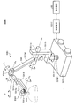
- FIG. 1 is a diagram illustrating an example of a schematic configuration of a microsurgery system to which the technology according to the present disclosure can be applied. It is a figure showing a situation of operation using a microscope operation system. It is a figure which shows an example of the control state which holds a zoom frame in the center part of a screen with which a microscope operation system is provided.
- FIG. 1 is a diagram illustrating an example of a schematic configuration of an endoscopic surgery system 5000 to which a medical observation system according to the present disclosure may be applied.
- FIG. 1 shows a state in which an operator (doctor) 5061 performs an operation on a patient 5071 on a patient bed 5069 using the endoscopic surgery system 5000.
- the scopist 5062 grasps the endoscope 5001 and inserts it into the body cavity of the patient 5071.
- the assistant 5063 grasps the surgical instrument 5017 and inserts it into the body cavity of the patient 5071.
- trocars 5025a to 5025d are punctured into the abdominal wall. Then, the lens barrel 5003 of the endoscope 5001 and other surgical tools 5017 are inserted into the body cavity of the patient 5071 from the trocars 5025a to 5025d.
- an insufflation tube 5019, an energy treatment tool 5021, and forceps 5023 are inserted into the body cavity of the patient 5071 as other operation tools 5017.
- the insufflation tube 5019 sends gas into the body cavity to inflate the body cavity of the patient 5071 for the purpose of securing the visual field by the endoscope 5001 and securing the working space of the operator 5061.
- the energy treatment device 5021 is a treatment device that performs incision and exfoliation of tissue, sealing of blood vessels, and the like by using high-frequency current and ultrasonic vibration.
- the insufflation tube 5019 and the energy treatment device 5021 are connected to a control device (not shown), and the operation device 5017 receiving an instruction from the operator 5061 or the like performs a predetermined operation.
- the illustrated surgical tool 5017 is merely an example, and various surgical tools generally used in an endoscopic operation, such as a set and a retractor, may be used as the surgical tool 5017.
- An image of an operation field in the body cavity of the patient 5071 captured by the endoscope 5001 (hereinafter, referred to as an operation field image) is displayed on the display device 50.
- the operator 5061 performs a procedure such as excision of an affected part using the energy treatment tool 5021 and the forceps 5023 while viewing the operation field image displayed on the display device 50 in real time.
- the scopist 5062 adjusts the position of the endoscope 5001 so that the affected area is displayed in the operative field image while viewing the operative field image displayed on the display device 50 in real time.
- the insufflation tube 5019, the energy treatment tool 5021, and the forceps 5023 are gripped by an operator 5061, an assistant 5063, and the like during the operation.
- the endoscope 5001 includes a lens barrel 5003 (also referred to as a scope) in which a region of a predetermined length from the distal end is inserted into a body cavity of the patient 5071, and a camera head 5005 connected to a proximal end of the lens barrel 5003. Be composed.
- a lens barrel 5003 also referred to as a scope
- a camera head 5005 connected to a proximal end of the lens barrel 5003.
- An opening in which the objective lens is fitted is provided at the tip of the lens barrel 5003.
- a light source device (not shown) is connected to the endoscope 5001, and light generated by the light source device is guided to the distal end of the lens barrel 5003 by a light guide extending inside the lens barrel 5003. Irradiation is performed toward an observation target in a body cavity of the patient 5071 through an objective lens.
- the endoscope 5001 may be a direct view, a perspective view, or a side view.
- An optical system and an image sensor are provided inside the camera head 5005, and the reflected light (observation light) from the observation target is focused on the image sensor by the optical system.
- the observation light is photoelectrically converted by the imaging element, and an electric signal corresponding to the observation light, that is, an image signal corresponding to the observation image is generated.
- the image signal is transmitted as raw data to a camera control unit (CCU) 12a.
- the camera head 5005 has a function of adjusting the magnification and the focal length by appropriately driving the optical system.
- the camera head 5005 may be provided with a plurality of image pickup devices.
- a plurality of relay optical systems are provided inside the lens barrel 5003 to guide observation light to each of the plurality of imaging elements.
- the endoscopic surgery system 5000 includes an input device that receives various information inputs and instruction inputs from a surgeon 5061, a scopist 5062, or an assistant 5063, which is a user.
- the user inputs various kinds of information related to surgery, such as patient's physical information and information about a surgical procedure, via an input device.
- the user drives the operation tool 5017 such as the energy treatment tool 5021 or the like via the input device, by instructing to change the imaging conditions (the type of irradiation light, the magnification, the focal length, and the like) by the endoscope 5001.
- the user inputs an instruction or the like that the user is to be made.
- the type of the input device is not limited, and the input device may be various known input devices.
- the input device for example, a mouse, a keyboard, a touch panel, a switch, and / or a lever can be applied.
- FIG. 1 shows an example in which a scopist 5062 inputs information using a foot switch 5057 which is an example of an input device.
- the scopist 5062 sets a region of interest in the operative field image via the foot switch 5057, and the like. Details will be described later.
- the touch panel may be provided on the display surface of the display device 50.
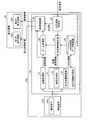
- FIG. 2 is a functional block diagram showing a functional configuration of the medical observation system 10a applied to the endoscopic operation.
- the medical observation system 10a is a system that is applied to, for example, the above-described endoscopic surgery system 5000 and monitors an operation field image using an endoscope 5001 inserted into a body cavity of a patient 5071 during a surgery.
- the medical observation system 10a is a system that displays an enlarged operation field image in which a set attention area is always enlarged based on the three-dimensional position of the operation field, regardless of the position and orientation of the endoscope 5001. .
- the medical observation system 10a includes an imaging device 42a and a camera control unit 12a.
- the imaging device 42a is mounted on the camera head 5005 of the endoscope 5001 and captures an operation field in a body cavity of the patient 5071 to obtain an operation field image.
- the camera control unit 12a generates an operation field image and generates three-dimensional information of the operation field when the imaging device 42a performs imaging.
- the imaging device 42a includes an imaging element 44a.
- the imaging element 44a is configured by an imaging element (photoelectric conversion element) such as a CMOS (Complementary Metal Oxide Semiconductor) image sensor or a CCD (Charge Coupled Device) image sensor, and converts light from an operation field into an electric signal. .
- CMOS Complementary Metal Oxide Semiconductor
- CCD Charge Coupled Device
- the camera control unit 12a includes a three-dimensional information generation unit 14, a development processing unit 18, an attention area setting unit 20, an attention area estimation unit 22, a three-dimensional map data storage unit 24, a zoom processing unit 26, And a control unit 40.
- the camera control unit 12a always generates an enlarged operation field image in which the region of interest is enlarged irrespective of the position and orientation of the endoscope, and causes the display device 50 to display the image.
- the camera control unit 12a is an example of the medical observation device according to the present disclosure.
- the three-dimensional information generation unit 14 calculates a three-dimensional position of, for example, an operation field image in a body cavity captured by the imaging element 44a.
- the three-dimensional information generator 14 includes a map generator 15 and a self-position estimator 16.
- the map generation unit 15 generates a three-dimensional map (hereinafter, simply referred to as a map) indicating a three-dimensional position of an operation field and a three-dimensional position of a region of interest described below. A method for generating a map will be described later.
- the self-position estimating unit 16 estimates the self-position and posture of the endoscope 5001 at the predetermined timing based on the generated map and the operation field image captured at a predetermined timing.
- the development processing unit 18 performs a development process for converting the imaging data into a viewable image.
- the development processing unit 18 performs various types of image processing for displaying an image, such as a development process (demosaicing process), on the RAW data output from the image sensor 44a. More specifically, the development processing unit 18 converts the RAW data into visible image data by applying a preset digital gain or gamma curve to the RAW data. It is desirable that the digital gain and the gamma curve to be set are adjusted in advance so that image data that is easy for the operator 5061 and the scopist 5062 to see is generated.
- the attention area setting unit 20 designates, for example, an area of interest, such as a tumor to be removed by surgery, from an operative field image captured by the imaging element 44a and converted to be visible by the development processing unit 18. More specifically, the operator of the medical observation system 10a sets at least one region of interest from the operative field image while monitoring the operative field image on the display device 50 such as a liquid crystal monitor. A specific method of setting the attention area will be described later. Note that the attention area setting unit 20 is an example of a setting unit according to the present disclosure.
- the attention area estimation unit 22 estimates the position of the attention area in the surgical field image at an arbitrary timing. Note that the attention area estimation unit 22 is an example of an estimation unit in the present disclosure.
- the three-dimensional map data storage unit 24 stores the three-dimensional map of the surgical field generated by the map generation unit 15 described above. Note that the three-dimensional map stored in the three-dimensional map data storage unit 24 is updated over time.
- the zoom processing unit 26 generates an enlarged operation field image obtained by enlarging the attention area estimated at the timing based on the position of the attention area estimated by the attention area estimation unit 22.
- the zoom processing unit 26 is an example of an enlarged image generation unit according to the present disclosure.
- the zoom processing unit 26 performs electronic zoom processing on the operative field image by, for example, interpolating pixel values between pixels. Interpolation of the pixel values may be performed using a known method such as the nearest neighbor method, the bilinear method, the bicubic method, and the Lanczos method. Further, the zoom processing unit 26 may perform the electronic zoom by performing the super-resolution processing.
- the zoom magnification may be a predetermined magnification set in advance, or may be automatically determined by the zoom processing unit 26 from the size of the attention area. Further, a user such as a scopist 5062 who is an operator may specify the magnification.
- the display control unit 40 performs display control to output the operation field image generated by the development processing unit 18 and the enlarged operation field image generated by the zoom processing unit 26 to the display device 50.
- the display device 50 various known display devices such as a liquid crystal display device or an EL (Electro Luminescence) display device can be applied.
- the display device 50 includes at least a first display area 52a for displaying an enlarged operation field image. Further, as shown in FIG. 2, the display device 50 may include a second display area 52b for displaying an operation field image, in addition to the first display area 52a.
- the display device 50 may include a first display region 52a and a second display region 52b in one monitor, or the display device 50 is configured by two different monitors, and The monitors may each include a first display area 52a and a second display area 52b.
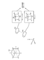
- FIG. 3 is a diagram illustrating a method in which the map generation unit 15 generates a three-dimensional map of an operation field.
- FIG. 3 illustrates a state in which the imaging device 42a observes the stationary object 100 in the three-dimensional space XYZ in which a point on the space is set as the reference position O. Then, the imaging device 42a captures the operation field image K (x, y, t) at a predetermined timing, for example, time t, and at a timing different from the predetermined timing, for example, time t + ⁇ t. , Y, t + ⁇ t). Note that the time interval ⁇ t is set to, for example, 33 msec.
- the reference position O may be set arbitrarily, but is desirably set, for example, to a position that does not move with time. Note that x in the surgical field image K (x, y, t) represents the horizontal coordinate of the image, and y represents the vertical coordinate of the image.
- the map generation unit 15 detects a feature point, which is a pixel serving as a feature, from the operative field image K (x, y, t) and the operative field image K (x, y, t + ⁇ t).
- the feature point is, for example, a pixel whose pixel value differs from an adjacent pixel by a predetermined value or more. Note that it is desirable that the feature points are points that exist stably even after a lapse of time. For example, pixels forming edges in an image are often used.
- feature points A1, B1, C1, D1, E1, F1, and H1, which are vertices of the object 100 are detected from the operative field image K (x, y, t). Suppose it was done.
- the map generation unit 15 searches the surgical field image K (x, y, t + ⁇ t) for points respectively corresponding to the feature points A1, B1, C1, D1, E1, F1, and H1. Specifically, based on the pixel value of the feature point A1, the pixel value near the feature point A1, and the like, a point having the same feature is searched for in the surgical field image K (x, y, t + ⁇ t). By this search processing, feature points A2, B2, C2, D2, E2 corresponding to feature points A1, B1, C1, D1, E1, F1, and H1 from the surgical field image K (x, y, t + ⁇ t). It is assumed that F2 and H2 are respectively detected.
- the map generation unit 15 for example, two-dimensional coordinates of the feature point A1 on the operative field image K (x, y, t + ⁇ t) and the operative field image K of the feature point A2 From the two-dimensional coordinates on (x, y, t + ⁇ t), the three-dimensional coordinates (X A , Y A , Z A ) of the point A in space are calculated. As a set of the three-dimensional coordinates (X A , Y A , Z A ) calculated in this way, a three-dimensional map D (X, Y, Z) of the space where the object 100 is placed is generated. The generated three-dimensional map D (X, Y, Z) is stored in the three-dimensional map data storage unit 24. Note that the three-dimensional map D (X, Y, Z) is an example of three-dimensional information in the present disclosure.
- the map generation unit 15 also estimates the position and orientation of the imaging device 42a at the same time.
- the operative field image K (x, y, t) and the operative field image K (x) are set as unknowns with the three-dimensional coordinates of each feature point constituting the object 100, the position and the posture of the imaging device 42a as unknowns.
- Y, t + ⁇ t a simultaneous equation is established based on the two-dimensional coordinates of the feature points respectively observed.
- the map generating unit 15 estimates the three-dimensional coordinates of each feature point constituting the object 100 and the position and orientation of the imaging device 42a by solving the simultaneous equations.
- a plurality of feature points are detected from the operative field image K (x, y, t) captured by the imaging device 42a, and those feature points are detected from the operative field image K (x, y, t + ⁇ t).
- a point corresponding to the feature point a three-dimensional map D (X, Y, Z) of the environment observed by the imaging device 42a can be generated.
- the position and orientation of the imaging device 42a that is, the self-position can be estimated.
- a feature point that was initially invisible becomes visible, so that the three-dimensional map D (X, Y, Z) can be expanded.
- the three-dimensional position of the same feature point can be repeatedly calculated. For example, by performing averaging processing, a calculation error can be reduced.
- the three-dimensional map D (X, Y, Z) stored in the three-dimensional map data storage unit 24 is updated as needed.
- the technique for creating a three-dimensional map of the environment and specifying the self-position of the imaging device 42a is generally called SLAM (Simultaneous Localization and Mapping) technology.
- the basic principle of SLAM technology using a monocular camera is described in, for example, "Andrew J. Davison," Real-Time Simultaneous Localization and Mapping with with a Single Camera "," Proceedings of the 9th IEEE IEEE International Conference on Computer Vision Volume 2, 2003. pp. 1403-1410 ".
- the SLAM technique for estimating the three-dimensional position of a subject using a camera image of the subject is also called Visual @ SLAM.
- the attention area is set by the operation of the attention area setting unit 20. Specifically, the attention area setting unit 20 superimposes and displays an attention frame indicating the attention area on the surgical field image, and specifies the size, shape, and position of the attention frame.
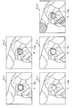
- FIG. 4 is a diagram showing an example of a method of setting a frame of interest.
- FIG. 4A is a diagram showing an example of an operation field image K (x, y) observed by the endoscope 5001.
- the information of the timing (for example, time) at which the operative field image was captured is omitted, and the operative field image is simply described as K (x, y).
- FIG. 4B shows an example in which the orientation of the endoscope 5001 is adjusted so that the affected area to be set as the attention area is displayed in the center of the surgical field image K (x, y), and the attention area setting unit 20 sets the attention area indicating the attention area.
- FIG. 3 is a diagram illustrating an example of a state in which a frame 110 is set.
- FIG. 4C is a diagram illustrating an example of an enlarged operative field image L (x, y) in which an area including the attention frame 110 is enlarged and displayed at a predetermined magnification.
- the scopist 5062 sets the specific position to be enlarged such as the affected part at the center (an example of a predetermined position) of the operation field image K (x, y).
- the endoscope 5001 is moved so as to be reflected.
- the scopist 5062 depresses the foot switch 5057 (FIG. 1) and The region setting unit 20 is instructed to set the region of interest.
- the setting signal instructing the setting of the attention area is generated with the stepping on of the foot switch 5057 as a trigger.
- the attention area setting unit 20 places an attention frame 110 of a predetermined size in the center of the surgical field image K (x, y), as shown in FIG. 4B. By displaying, the attention area is set.
- the size and shape of the attention frame 110 may be set arbitrarily, but will be described later in detail.
- the method of setting the attention area by the attention area setting unit 20 is not limited to the above-described method.
- a touch panel may be provided by being stacked on the screen of the display device 50, and by detecting an operation of the touch panel, the attention area may be set at a position where the touch panel is pressed. Further, the position and shape of the attention area may be set by a mouse. Furthermore, the attention area setting unit 20 may set the position and shape of the attention area based on an operation such as a gesture.
- FIG. 5 is a diagram showing another example of a method of setting the attention frame.
- FIG. 5A is a diagram showing an example of an operation field image K (x, y) observed by the endoscope 5001. While viewing the operation field image K (x, y) displayed on the display device 50, the scopist 5062 specifies the position of the region of interest using an input device such as a touch panel or a mouse.
- the attention area setting unit 20 displays the attention area instruction information 105 indicating the designated area by superimposing the attention area image K (x, y).
- the attention area setting unit 20 sets the attention frame 110 at the position of the input attention area instruction information 105.
- the attention area setting unit 20 displays the set attention frame 110 as shown in FIG. 5B so as to be superimposed on the operation field image K (x, y).
- the attention frame 110 may be a frame of a preset size and shape, or may be a closed region imitating the attention region instruction information 105.
- the zoom processing unit 26 enlarges the set attention frame 110 at a predetermined magnification, as shown in FIG. 5C, at the enlarged operation field image L (x, y). Is generated and displayed.
- the attention area setting unit 20 uses the three-dimensional map D (X, Y, Z) to take into account conditions such as a distance in a three-dimensional space and a distance from an imaging system within a certain range. To set the attention area.
- the display form of the attention frame 110 is not limited to those shown in FIGS. Variations of the display form of the attention frame 110 will be described later (see FIG. 18).
- the attention area setting unit 20 may set the position and shape of the attention area based on an operation such as a gesture.
- the zoom processing unit 26 enlarges an area including the attention frame 110 of the operation field image K (x, y) at a predetermined magnification, and enlarges the operation field image L (x, y). Generate At this time, as shown in FIG. 4C, the attention frame 110 is also enlarged and displayed at a predetermined magnification. Then, the display control unit 40 outputs the generated enlarged operative field image L (x, y) to the display device 50 and displays it. The surgeon 5061 performs an operation while observing the enlarged operation field image L (x, y) displayed on the display device 50.
- the medical observation system 10a captures the operation field image K (x, y) at a predetermined time interval ⁇ t. Is repeated. Then, each time the operation field image K (x, y) is captured, generation and display of a new enlarged operation field image L (x, y) are repeated.
- the attention area estimation unit 22 estimates the location of the attention area from the operative field image K (x, y).
- the zoom processing unit 26 generates an enlarged operation field image L (x, y) in which the estimated attention area is enlarged at a predetermined magnification.
- the display control unit 40 outputs the enlarged operative field image L (x, y) to the display device 50 to be displayed, as shown in FIG. 4C.
- the medical observation system 10a continues to display the enlarged operative field image L (x, y) on the display device 50.
- the attention area estimation unit 22 estimates the location of the attention area from the operative field image K (x, y) when the position or orientation of the endoscope 5001 changes.
- the attention area estimation unit 22 determines the position and orientation of the endoscope 5001 at a predetermined timing, for example, time t, the timing and the position of the endoscope 5001 at a time different from the predetermined timing, for example, time t + ⁇ t, Based on the map D (X, Y, Z), it is estimated at which position of the attention frame 110 at time t in the surgical field image K (x, y, t + ⁇ t) at time t + ⁇ t. .
- the attention area estimation unit 22 determines how the plurality of feature points near the set attention frame 110 move between time t and time t + ⁇ t. Identify what you have done. Then, the attention area estimation unit 22 estimates the position of the attention area based on the movement state of the specified feature point.
- the region set as the region of interest is generally an affected part to be operated.
- the affected area is likely to be resected, bleeding, or significantly deformed by surgery. Therefore, even if a feature point is set inside the attention area, the feature point may disappear with the passage of time. Therefore, it is desirable to extract a feature point from an area excluding the periphery of the attention area from the operative field image K (x, y) after the attention area is set.
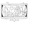
- FIG. 6 is an image showing an example in which a region for extracting a feature point is set.
- the map generation unit 15 sets the mask 120 around the screen, avoiding the center of the screen where the attention frame 110 is set, as shown in FIG. Then, the map generation unit 15 extracts a feature point only inside the set mask 120. Since the set area of the mask 120 is apart from the attention frame 110 indicating the position of the attention area, it is assumed that the deformation during the operation is small. Therefore, the feature points can be stably detected inside the mask 120 regardless of the passage of time. Since the feature points can be stably extracted, the stability of the estimation accuracy of the three-dimensional map D (X, Y, Z) and the position and orientation of the endoscope 5001 is improved.
- the map generation unit 15 may have a function of removing a previously registered object such as a surgical instrument or a finger from the operative field image K (x, y). This removal function is, for example, a function of recognizing an image of a previously registered object and excluding a region where the recognized object exists from being calculated.
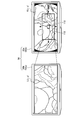
- FIG. 7 is a diagram illustrating an example of an image displayed by the medical observation system 10a.
- the display control unit 40 outputs the operative field image K (x, y) monitored by the scopist 5062 to the display device 50a (the second display area 52b) and displays it.
- the display control unit 40 outputs the enlarged operation field image L (x, y) monitored by the operator 5061 to a display device 50b (first display area 52a) different from the display device 50a and displays the same.
- the surgeon 5061 and the scopist 5062 can arrange the display devices 50a and 50b at positions that are easy to see. Therefore, the surgeon 5061 can facilitate the operation while observing the enlarged operation field image L (x, y). Further, the scopist 5062 can easily adjust the position of the endoscope 5001 while observing the operation field image K (x, y).
- the above-mentioned attention frame 110 and a zoom frame 112 indicating the range of the enlarged operation field image L (x, y) are displayed. You may.
- the attention frame 110 and the zoom frame 112 move in the operation field image K (x, y) according to the movement of the endoscope 5001.
- the scopist 5062 checks only the operation field image K (x, y) and performs the enlargement operation. It is possible to immediately confirm whether an appropriate range is displayed in the field image L (x, y). If it is not necessary to display the attention frame 110 and the zoom frame 112, these displays may be turned on / off independently by an operation instruction of the scopist 5062.
- the medical observation system 10a generates the three-dimensional map D (X, Y, Z) and estimates the position and orientation of the endoscope 5001, so that the three-dimensional position of a feature point near the attention area is determined. Can be calculated. Therefore, by performing perspective transformation and / or rotation transformation of the captured operation field image K (x, y), an enlarged operation field image L (x, y) in which the attention area is always viewed from the same direction is generated and displayed. It can also be done.
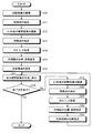
- FIG. 7 is a flowchart illustrating an example of the flow of a process performed by the medical observation system 10a.
- the imaging element 44a captures an operation field image K (x, y) (Step S10).
- the map generation unit 15 extracts a feature point from the captured surgical field image K (x, y) (step S11).
- the imaging element 44a captures an operation field image K (x, y) at a predetermined timing, for example, ⁇ t seconds later (step S12).
- the map generation unit 15 extracts a feature point from the captured operative field image K (x, y) after ⁇ t seconds (step S13).
- the map generation unit 15 generates a three-dimensional map D (X, Y, Z) by calculating a three-dimensional position of a feature point (step S14).
- the self-position estimating unit 16 estimates the position and orientation of the endoscope 5001 (Step S15).
- the attention area setting unit 20 sets an attention area in the operative field image K (x, y) (step S16).
- the zoom processing unit 26 generates the enlarged operation field image L (x, y). Then, the display control unit 40 causes the display device 50 to display the generated enlarged operative field image L (x, y) (Step S17).
- the display control unit 40 determines whether there is an instruction to end the process (Step S18). If it is determined that there is an end instruction (step S18: Yes), the medical observation system 10a ends the processing in FIG. On the other hand, if it is not determined that there is an end instruction (step S18: No), the process proceeds to step S19.
- the instruction to end the process is performed by detecting an operation such as turning off a power switch (not shown) of the camera control unit 12a.
- step S18 the imaging element 44a captures an operation field image K (x, y) at a predetermined timing, for example, ⁇ t seconds later (step S19).
- the map generation unit 15 extracts a feature point from the photographed surgical field image K (x, y) after ⁇ t seconds (step S20).
- the map generation unit 15 updates the three-dimensional map D (X, Y, Z) generated in step S14 by calculating the three-dimensional position of the feature point (step S21).
- the self-position estimating unit 16 estimates the position and orientation of the endoscope 5001 (Step S22).
- the attention area estimation unit 22 estimates the position of the attention area in the surgical field image K (x, y) after ⁇ t seconds captured in step S19 (step S23). Thereafter, the process returns to step S17.
- the three-dimensional information generation unit 14 converts the three-dimensional information of the surgical field from the surgical field image K (x, y) captured by the imaging device 42a.
- a dimensional map D (X, Y, Z) (three-dimensional information) is generated.
- the attention area setting section 20 sets at least one attention area in the surgical field image K (x, y) captured at a predetermined timing.
- the attention area estimation unit 22 (estimation unit) performs imaging at a timing different from the predetermined timing based on the three-dimensional map D (X, Y, Z) and the position of the attention area set by the attention area setting unit 20.
- the existence position of the attention area is estimated from the obtained operation field image K (x, y). Then, the zoom processing unit 26 (enlarged image generation unit) generates an enlarged operation field image L (x, y) in which the estimated attention area is enlarged at a predetermined magnification, and the display control unit 40 performs at least the enlargement operation. A field image L (x, y) is output. Therefore, even when the endoscope 5001 on which the imaging device 42a is mounted changes its position or posture, it is possible to continue observing the diseased part in an enlarged manner from a remote position.
- the display control unit 40 displays the operative field image K (x, y) and the enlarged operative field image L (x, y). Therefore, both the enlarged operation field image L (x, y) that the operator 5061 wants to see and the operation field image K (x, y) that the scopist 5062 wants to see can be displayed.
- the display control unit 40 controls the two display devices 50a and 50b to display the operative field image K (x, y) and the enlarged operative field image L ( x, y). Therefore, the surgeon 5061 and the scopist 5062 can arrange the display devices 50a and 50b at positions that are easy to see.
- the attention area setting unit 20 sets the operation field image K (x, y) displayed on the display device 50 by the display control unit 40.
- the specific position is designated as the region of interest on condition that a setting signal instructing the setting of the region of interest is generated in a state where the specific position matches the predetermined position of the display device 50. Therefore, the attention area can be set easily and surely by the routine operation.
- the attention area setting unit 20 sets the operation area image K (x, y) displayed on the display device 50 by the display control unit 40. At the position specified by the input device. Therefore, the attention area can be easily and reliably set by an intuitive operation.
- the imaging device 42a includes one imaging element 44a, and the three-dimensional information generation unit 14 determines at least two images captured by the imaging device 42a at different times.
- a three-dimensional map D (X, Y, Z) (three-dimensional information) of the operative field is generated based on the operative field images K (x, y). Therefore, using the imaging device 42a having a simple configuration including only the single-lens camera, the affected part can be continuously observed while being enlarged from a distant position.
- the imaging device 42a is mounted on the endoscope 5001. Therefore, when performing an operation or the like using the endoscope 5001, the operator 5061 can enlarge the affected part and observe it stably.
- the three-dimensional information generating unit 14 converts the three-dimensional information of the surgical field from the surgical field image K (x, y) obtained by capturing the surgical field.
- a map D (X, Y, Z) (three-dimensional information) is generated.
- the attention area setting unit 20 sets at least one attention area in the operative field image K (x, y) captured at a certain time.
- the attention area estimation unit 22 (estimation unit) is imaged at a time different from the time based on the three-dimensional map D (X, Y, Z) and the position of the attention area set by the attention area setting unit 20.
- the zoom processing unit 26 (enlarged image generation unit) generates an enlarged operation field image L (x, y) obtained by enlarging the estimated attention area at a predetermined magnification, and the display control unit 40 performs at least the enlargement operation.
- the field image L (x, y) is displayed. Therefore, the affected part can be continuously observed while being enlarged.
- the endoscope 5001 including the imaging device 42a may include an acceleration sensor such as a gyro sensor.
- an acceleration sensor such as a gyro sensor.
- the position and orientation of the endoscope 5001 can be measured in real time. Therefore, the position and orientation of the endoscope 5001 can be measured without the imaging device 42a capturing two images at different times, and thereby, the position of the attention area can be estimated.
- the configuration of the medical observation system 10a is not limited to the configuration described in the first embodiment, and various modifications can be realized.
- another embodiment of the medical observation system will be described step by step.
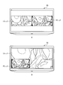
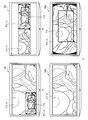
- FIG. 9 is a diagram illustrating an example of a display mode of an image output from the display control unit 40 to the display device 50. That is, in the first embodiment, the display control unit 40 outputs only the enlarged operative field image L (x, y) to the display device 50, and the display device 50 displays the operative field image K on different display devices 50a and 50b. An example in which (x, y) and the enlarged operation field image L (x, y) are output has been described, but the display form of the output image is not limited thereto.
- 9A is an example in which the display control unit 40 causes the display device 50 to display the operation field image K (x, y) and the enlarged operation field image L (x, y) adjacent to each other (side-by-side). That is, the enlarged operation field image L (x, y) is displayed on the first display area 52a set on the display screen of the display device 50, and the operation field image K (x, y) is displayed on the second display area 52b. Is displayed.
- the operator 5061 can proceed with the surgery while observing the enlarged operation field image L (x, y), and the scopist 5062 can perform the operation field image K (x, y).
- the position of the endoscope 5001 can be adjusted.
- FIG. 9B shows an example in which the display control unit 40 superimposes (in PinP) an operation field image K (x, y) on a part of the enlarged operation field image L (x, y) and displays the image on the display device 50. It is. In this case, the second display area 52b is superimposed on a part of the first display area 52a.
- the operator 5061 can proceed with the surgery while observing the enlarged operation field image L (x, y), and the scopist 5062 can perform the operation field image K (x, y).
- the position of the endoscope 5001 can be adjusted.
- the position at which the operation field image K (x, y) is superimposed is not limited to the example of FIG. 9B, and may be any of the upper left, upper right, and lower right positions of the enlarged operation field image L (x, y). May be superimposed.
- the display control unit 40 displays the operative field image K (x, y) and the enlarged operative field image L (x, y) on one display device 50 adjacent to each other. And display it. Therefore, both the enlarged operation field image L (x, y) that the operator 5061 wants to see and the operation field image K (x, y) that the scopist 5062 wants to see can be displayed.
- the display control unit 40 superimposes the operation field image K (x, y) on a part of the enlarged operation field image L (x, y) on one display device 50. To display. Therefore, both the enlarged operation field image L (x, y) that the operator 5061 wants to see and the operation field image K (x, y) that the scopist 5062 wants to see can be displayed. In particular, the enlarged operation field image L (x, y) can be displayed as large as possible.
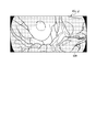
- FIG. 10 is a diagram illustrating an example of a process performed when the zoom frame reaches an end of the operation field image K (x, y) as the endoscope 5001 moves.
- the zoom frame is a frame indicating a display range of the enlarged operative field image L (x, y).
- the surgical field image K (x, y) observed by the endoscope 5001 has a circular shading area 130 around it. Since the shading area 130 is an area where light does not reach, it is observed as a black area as shown in FIG. 10A.
- the zoom frame may reach the end of the operation field image K (x, y).
- the medical observation system 10a takes one of the three processing modes prepared in advance.
- FIG. 10B is an example in which, when the zoom frame 112a reaches the end of the operative field image K (x, y), an area without image information is displayed in black. That is, the zoom processing unit 26 sets a predetermined pixel value (for example, a black pixel) in an area of the zoom frame 112a that exceeds the edge of the surgical field image K (x, y) and an area that overlaps the shaded area 130. An enlarged operative field image L (x, y) that stores the pixel value 0) is generated. Then, the display control unit 40 displays the generated enlarged operation field image L (x, y).
- a predetermined pixel value for example, a black pixel
- the zoom frame 112a reaches the position shown in FIG. 10A
- the enlarged surgical field image L ( (x, y) is displayed.
- the scopist 5062 immediately recognizes that the position of the endoscope 5001 has reached the end of the operation field image K (x, y) since the black region is enlarged. be able to. Then, by adjusting the position of the endoscope 5001, the scopist 5062 can regenerate the enlarged operative field image L (x, y).
- FIG. 10C is an example in which, when the zoom frame 112a reaches the end of the operation field image K (x, y), the screen end is kept displayed as it is. That is, the zoom processing unit 26 determines that the edge of the zoom frame 112a, that is, the edge of the enlarged operative field image L (x, y) matches the edge of the operative field image K (x, y). Even if the endoscope 5001 further moves beyond the edge of the operation field image K (x, y), the position of the zoom frame 112a is maintained and the enlarged operation field image L (x, y) is maintained. Generate Then, the display control unit 40 displays the generated enlarged operation field image L (x, y).
- the zoom frame 112a when the zoom frame 112a reaches the position shown in FIG. 10A, the zoom frame 112a is moved to the position of the zoom frame 112b, and the image inside the moved zoom frame 112b is enlarged. (X, y). That is, at this time, the left end of the zoom frame 112b matches the left end of the operation field image K (x, y). With this display mode, the display area of the enlarged operative field image L (x, y) is held at the end of the operative field image K (x, y) regardless of the movement of the endoscope 5001. be able to.
- FIG. 10D is an example in which the zoom processing unit 26 stops generating the enlarged operative field image L (x, y) when the zoom frame 112a reaches the end of the operative field image K (x, y). Then, at this time, the display control unit 40 displays the operation field image K (x, y).
- the display of the enlarged operative field image L (x, y) is released by the scopist 5062, so that the imaging range of the endoscope 5001 is changed to the operative field image K (x, y).
- the end can be immediately recognized.
- the scopist 5062 can regenerate the enlarged operative field image L (x, y).
- the zoom processing unit 26 determines whether the zoom frame 112a has reached the edge of the operative field image K (x, y), or When the image K (x, y) overlaps with the shaded area, the enlarged operation field storing a predetermined pixel value is stored in the area of the zoom frame 112a that exceeds the edge and overlaps with the shaded area. Generate an image L (x, y). Therefore, the scopist 5062 can immediately recognize that the zoom frame 112a has reached the edge of the operation field image K (x, y). Then, the scopist 5062 can adjust the position of the endoscope 5001 so that the scoring does not occur.
- the zoom processing unit 26 (enlarged image generation unit) An enlarged operative field image L (x, y) in which the edge of L (x, y) matches the edge of the operative field image K (x, y) is generated. Therefore, it is possible to continue to display the enlarged surgical field image L (x, y) without any shading.
- the zoom processing unit 26 determines whether the zoom frame 112a has reached the edge of the operative field image K (x, y) or the operative field image K If the area overlaps the (x, y) shaded area, the generation of the enlarged operative field image L (x, y) is stopped. Therefore, the scopist 5062 can immediately recognize that the imaging range of the endoscope 5001 has reached the end of the operation field image K (x, y). Then, the scopist 5062 can adjust the position of the endoscope 5001 so that the scoring does not occur.
- the medical observation system 10a has been described assuming that the imaging device 42a has one imaging element 44a.
- the configuration of the imaging device is not limited to this.
- FIG. 11 is a diagram illustrating an example of a schematic configuration of a medical observation system 10b in which the imaging device 42b includes an imaging element 44b including an image plane phase difference sensor 46.
- FIG. 11 FIG. 2 is partially omitted, and unless otherwise noted, the omitted portions have the same configuration as FIG.
- the image plane phase difference sensor 46 has a configuration in which pixels for distance measurement are discretely arranged in the image sensor 44b.
- the map generation unit 15 uses the image plane phase difference information output from the image plane phase difference sensor 46 to obtain depth information (distance) to the imaged object 100. Information). Therefore, the SLAM technology can be effectively used.
- the image plane phase difference sensor 46 can obtain depth information from only one captured image.
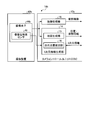
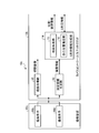
- FIG. 12 is a diagram illustrating an example of a schematic configuration of a medical observation system 10c in which the imaging device 42c includes two imaging elements 44c and 44d.
- the two image sensors 44c and 44d are arranged in a state where a predetermined relative relationship is maintained, and image different places of the affected part so as to partially overlap. More specifically, the imaging elements 44c and 44d respectively acquire right-eye and left-eye image signals corresponding to stereoscopic vision.
- FIG. 2 is partially omitted, and unless otherwise specified, the omitted portions have the same configuration as FIG.
- the camera control unit 12b includes a depth information generation unit 30 in addition to the configuration described with reference to FIG.
- the depth information generation unit 30 generates depth information by performing matching between two operation field images captured by the two imaging elements 44c and 44d, respectively.
- the map generation unit 15 uses the depth information generated by the depth information generation unit 30 and the operation field images captured by the imaging elements 44c and 44d, respectively.
- the three-dimensional map D (X, Y, Z) can be generated by utilizing the SLAM technology.
- the two imaging elements 44c and 44d can perform imaging simultaneously, depth information can be obtained from two images obtained by one imaging. Therefore, even when the object is moving, the three-dimensional position of the object can be measured with high accuracy.
- the imaging device 42c includes the two imaging elements 44c and 44d that capture images in different ranges where a part of the imaging device 42c overlaps, and the three-dimensional information generation unit 14 performs two imaging operations.
- the elements 44c and 44d generate three-dimensional information of the operation field based on the two operation field images K (x, y) captured at the same time. Therefore, since depth information can be obtained from two operation field images K (x, y) obtained by one imaging, even when the operation field is moving, the three-dimensional position of the operation field can be obtained. Can be measured with high accuracy.
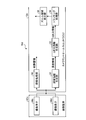
- FIG. 13 is a diagram illustrating an example of a schematic configuration of a medical observation system 10d in which the imaging device 42c includes two imaging elements and the camera control unit 12c includes the tracking processing unit 34. Note that FIG. 13 partially illustrates FIG. 2 and omits parts having the same configuration as FIG. 2 unless otherwise specified.
- the camera control unit 12c of the medical observation system 10d includes a depth information generation unit 30, a three-dimensional information generation unit 32, a tracking processing unit 34, and a zoom area calculation unit 36.
- the three-dimensional information generation unit 32 is provided in place of the three-dimensional information generation unit 14 (FIG. 2), and based on the depth information generated by the depth information generation unit 30, the three-dimensional information K (x, y) Generate dimensional information.
- the tracking processing unit 34 is provided in place of the three-dimensional map data storage unit 24 (FIG. 2), and superimposes two point groups based on the three-dimensional information of the immediately preceding frame and the three-dimensional information of the current frame.
- the difference between the position and orientation of the imaging device 42c is calculated by using the ICP (Iterative @ Closest @ Point) method or the like.
- the zoom area calculation unit 36 is provided in place of the attention area estimation unit 22 (FIG.
- the zoom area calculation unit 36 displays the attention area on the screen. Calculate the coordinates. Then, the above-described zoom processing unit 26 (FIG. 2) performs a zoom process on the region calculated by the zoom region calculation unit 36, and generates an enlarged operation field image L (x, y).
- the attention area in the surgical field image K (x, y) can be stably tracked without depending on the movement of the imaging device 42c.
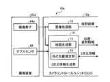
- FIG. 14 is a diagram illustrating an example of a schematic configuration of a medical observation system 10e in which the imaging device 42d includes the imaging element 44a and the depth sensor 48.
- FIG. 2 is partially omitted, and unless otherwise specified, the omitted portions have the same configuration as FIG.
- the ⁇ depth sensor 48 is a so-called 3D sensor that measures the distance to the subject.
- the depth sensor 48 is a so-called ToF (Time @ of @ Flight) sensor that measures the flight time of light and measures the distance to the object by receiving reflected light, such as infrared light, radiated toward the object. is there.
- the depth sensor 48 is realized by a so-called pattern projection method (Structured @ Light) that measures the distance to the subject by capturing images of projection light having a plurality of different geometric patterns applied to the subject.
- the map generation unit 15 extracts depth information (distance information) up to the imaged object 100 based on the operation field image K (x, y) captured by the imaging element 44a and the distance output by the depth sensor 48. More specifically, the map generation unit 15 calculates which pixel of the surgical field image K (x, y) captured by the image sensor 44a corresponds to the point measured by the depth sensor 48. Then, the map generator 15 generates a three-dimensional map D (X, Y, Z) (three-dimensional information) of the surgical field. Therefore, the SLAM technology can be effectively used.
- the imaging device 42d includes the one imaging element 44a and the depth sensor 48 (distance measurement device) that measures the distance to the target, and includes the three-dimensional information generation unit 14 Generates a three-dimensional map D (X, Y, Z) (three-dimensional information) of the operation field based on the image captured by the image sensor 44a and the distance measured by the depth sensor 48. Therefore, the distance to the operation field can be easily and reliably measured.
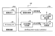
- FIG. 15 is a diagram illustrating an example of a schematic configuration of a medical observation system 10f in which the imaging device 42d includes the imaging element 44a and the depth sensor 48 and the camera control unit 12d includes the tracking processing unit 34.
- FIG. 2 is partially omitted, and unless otherwise specified, the omitted portions have the same configuration as FIG.
- the camera control unit 12d of the medical observation system 10f includes a three-dimensional information generation unit 32, a tracking processing unit 34, and a zoom area calculation unit 36.
- the three-dimensional information generation unit 32 is provided in place of the three-dimensional information generation unit 14 (FIG. 2), and two pieces of distance information measured by the depth sensor 48 from different positions (for example, a pixel value corresponding to the distance to the subject is displayed).
- the moving state of the operation field is obtained by matching the stored distance images.
- the tracking processing unit 34 is provided in place of the three-dimensional map data storage unit 24 (FIG. 2), and calculates a difference between the position and the posture of the imaging device 42c based on the above-described moving state of the operation field.
- the zoom area calculation unit 36 is provided in place of the attention area estimation unit 22 (FIG.
- the zoom area calculation unit 36 displays the attention area on the screen. Calculate the coordinates. Then, the above-described zoom processing unit 26 (FIG. 2) performs a zoom process on the region calculated by the zoom region calculation unit 36, and generates an enlarged operation field image L (x, y).
- the attention area in the surgical field image K (x, y) can be stably tracked without depending on the movement of the imaging device 42d.
- FIG. 16 is a diagram illustrating an example in which a plurality of attention frames 110a and 110b are set in the operative field image K (x, y).
- the attention area setting unit 20 may set a plurality of attention areas in the surgical field image K (x, y). For example, when it is necessary to pay attention to a plurality of affected areas, the attention area setting unit 20 sets attention frames 110a and 110b indicating each attention area based on the instruction of the scopist 5062. Then, the display control unit 40 causes the display device 50 to display two enlarged operation field images L (x, y) obtained by enlarging the area of the zoom frame corresponding to each of the attention frames 110a and 110b.
- the region of interest setting unit 20 sets a plurality of regions of interest. Therefore, it is possible to display an enlarged operation field image L (x, y) in which a plurality of attention areas are enlarged.
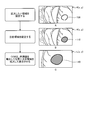
- FIG. 17 is a diagram showing an example in which a region within a predetermined distance range is highlighted from the surgical field image K (x, y).
- the attention area setting unit 20 displays a predetermined distance range area in the operation field image K (x, y) with a predetermined coloring as shown in FIG.
- FIG. 17 is an example in which a region R1 having a distance shorter than the distance d1 and a region R2 having a distance longer than the distance d2 are displayed in different colors. Note that this is a process performed to limit the distance range to the attention area between the distance d1 and the distance d2 in order to facilitate setting of the attention area.
- the values of the distance d1 and the distance d2 are, for example, as shown in FIG. 17, the attention area setting unit 20 displays a distance scale near the operative field image K (x, y), and the scopist 5062
- the setting may be made by operating an input device such as a touch panel. Then, according to the set values of the distance d1 and the distance d2, the attention area setting unit 20 displays the area R1 and the area R2 on the operation field image K (x, y) in real time by coloring. At this time, the operator points the input device at a position of a desired distance on the distance scale to set the distance d1 or the distance d2.
- the attention area setting unit 20 displays a color colored in the dragged distance range on the distance scale as shown in FIG.
- the GUI Graphic User Interface
- the operator can easily recognize a region corresponding to the distance range set by the operator in the operation field image K (x, y).
- the method of displaying the set distance range on the distance scale is not limited to the method shown in FIG. 17, and other display forms may be used as long as the set distance range is clearly indicated. May be taken.
- the display control unit 40 causes the display device 50 to display the operative field image K (x, y) in which the region R1 and the region R2 are displayed in color. Then, the scopist 5062 sets a region of interest according to the above-described procedure (see FIG. 4) while viewing the surgical field image K (x, y) in which the region R1 and the region R2 are displayed in color.
- the attention area setting unit 20 (setting unit) further includes the function of specifying the distance range in which the attention area exists, and the attention area setting unit 20 (setting unit) Set the area. Therefore, the scopist 5062 can more easily set the attention area.
- FIG. 18 is a diagram showing an example of a display form of the attention frames 110c to 110g set in the operation field image K (x, y).
- FIG. 18A is an example in which the attention frame 110c is displayed as a circular area.
- FIG. 18B is an example in which the attention frame 110d is indicated by a colored (highlighted) closed region.
- FIG. 18C is an example in which the attention frame 110e is indicated by a symbol.
- FIG. 18D is an example in which the attention frame 110f is indicated by a closed curve.
- FIG. 18E is an example in which both the attention frame 110g and the area having the same distance as the position where the attention frame 110g is set are colored and displayed.
- the scopist 5062 can recognize that another area exists at a position at the same distance as the attention area. Therefore, the endoscope 5001 can be more carefully grasped so that the tracking of the attention area is not deviated by erroneously turning the endoscope 5001 in the direction of another area.
- the form of the attention frame to be displayed may be set in the attention area setting unit 20 in advance by the scopist 5062.
- the method of setting the attention frames 110c to 110g may follow the method described with reference to FIG. 4 or FIG.
- FIG. 18B, FIG. 18D, and FIG. 18E when the attention frame is set as a closed region of an arbitrary shape, as described with reference to FIG. , Y), it is efficient to directly set the position and shape of the frame of interest.
- the attention frames 110c to 110g in a form that is easy for the operator to see can be displayed in the set attention area.
- FIG. 19 is a diagram illustrating an example of a setting method of the zoom frame 112.
- the scopist 5062 may set a magnification for enlarging the operation field image K (x, y).
- the setting of the magnification is performed, for example, by the zoom processing unit 26 of FIG. 2 instructing the display control unit 40 to superimpose the operation field image K (x, y) on the display device 50 and select a plurality of selectable zoom frames 112. (112c to 112f) may be displayed, and the operator may designate one of the zoom frames.
- FIG. 19 shows an example in which a zoom frame 112e indicating a magnification of 1.5 is specified. Note that the selection of the zoom frame 112 may be performed by, for example, operating an input device such as a switch provided near the endoscope 5001.
- the zoom processing unit 26 may generate the enlarged operative field image L (x, y) at a magnification according to the distance to the attention area. That is, based on the three-dimensional map D (X, Y, Z) generated by the three-dimensional information generation unit 14 and stored in the three-dimensional map data storage unit 24, the zoom processing unit 26 calculates, for example, the distance to the attention area. Is calculated. Then, a magnification for generating the enlarged operative field image L (x, y) is determined according to the calculated distance to the attention area. Also, an AF (Auto Focus) function is implemented in the imaging device 42a, and the imaging device 42a calculates a distance to the attention area by focusing on the position of the attention area estimated by the attention area estimation unit 22. You may. For example, when the distance to the attention area is long, the magnification can be set high, and when the distance to the attention area is short, the magnification can be set low.
- the scopist 5062 easily sets the magnification by selecting one zoom frame from the plurality of zoom frames 112c to 112f displayed on the display device 50. be able to.
- the zoom processing unit 26 (the enlarged image generation unit) generates the enlarged operation field image L (x, y) at a magnification corresponding to the distance to the attention area. Therefore, even when the endoscope 5001 moves in the front-rear direction with respect to the diseased part, the diseased part can be continuously observed at a fixed size.
- FIG. 20 is a diagram illustrating an example of a display method of the zoom frame 112 when the medical observation system 10a is operated.
- the zoom processing unit 26 may cause the display control unit 40 to display the zoom frame 112 so as to be superimposed on the operation field image K (x, y) displayed on the display device 50.
- FIG. 20A is an example in which the zoom frame 112 is displayed in the operation field image K (x, y) displayed so as to be superimposed on a part of the enlarged operation field image L (x, y).
- FIG. 20B is an example in which the zoom frame 112 is displayed in the operation field image K (x, y) displayed adjacent to the enlarged operation field image L (x, y).
- FIG. 20C shows the zoom frame 112 displayed in the operative field image K (x, y) displayed on a display device 50a different from the display device 50b displaying the enlarged operative field image L (x, y). It is an example.
- the scopist 5062 can easily confirm the position of the zoom frame 112. Therefore, since the scopist 5062 can predict in advance that the zoom frame 112 will reach the edge of the screen, the display range of the enlarged operative field image L (x, y) is smaller than that of the operative field image K (x, y). It is possible to prevent the occurrence of skewing due to exceeding the margin.
- the image may be subjected to camera shake correction processing or exposure amount adjustment.
- the camera shake correction processing is performed by, for example, the zoom processing unit 26 in FIG. 2, and the adjustment of the exposure amount is performed by the development processing unit 18 in FIG.
- the zoom processing unit 26 performs an operation on the operative field image K (x, y) and the enlarged operative field image L (x, y) between a plurality of captured images. And the like, and the movement amount and the movement direction. Then, by electronically shifting the captured image according to the calculated moving amount and moving direction, an image in which camera shake is corrected is generated. Since the enlarged operative field image L (x, y) is an image obtained by observing a smaller area than the operative field image K (x, y), the blurring of the image caused by camera shake increases. Therefore, it is desirable that the zoom processing unit 26 performs a camera shake correction with a higher correction effect than the camera shake correction on the operation field image K (x, y) on the enlarged operation field image L (x, y).
- the development processing unit 18 separately sets the digital gain and the gamma curve for the operation field image K (x, y) and the enlarged operation field image L (x, y), thereby individually setting the exposure amount. May be adjusted.
- the zoom processing unit 26 shakes the operative field image K (x, y) and the enlarged operative field image L (x, y). Make corrections. Therefore, even if a camera shake occurs in the surgical field image K (x, y) captured by the endoscope 5001, the easy-to-view surgical field image K (x, y) in which the camera shake is corrected and the enlarged surgical field are displayed. An image L (x, y) can be obtained.
- FIG. 21 is a diagram illustrating an example of a schematic configuration of a microsurgery system 5300 to which the technology according to the present disclosure can be applied.
- the microsurgery system 5300 includes a microscope device 5301, a control device 5317, and a display device 50.
- the “user” means any medical staff using the microsurgery system 5300, such as an operator and an assistant.
- the microscope apparatus 5301 includes a microscope section 5303 for magnifying and observing an observation target (operated part of a patient), an arm section 5309 supporting the microscope section 5303 at the distal end, and a base section 5315 supporting a base end of the arm section 5309. And
- the microscope section 5303 includes a substantially cylindrical tubular section 5305 and an imaging section (not shown) provided inside the tubular section 5305.
- the microscope unit 5303 is an electronic imaging microscope unit (a so-called video microscope unit) that electronically captures a captured image using the imaging unit.
- the imaging unit is an example of an imaging device according to the present disclosure.
- a cover glass for protecting the internal imaging unit is provided on the opening surface at the lower end of the cylindrical portion 5305.
- Light from the observation target (hereinafter, also referred to as observation light) passes through the cover glass and enters the imaging unit inside the cylindrical portion 5305.
- a light source made of, for example, an LED (Light Emitting Diode) may be provided inside the cylindrical portion 5305. At the time of imaging, light is emitted from the light source to the observation target via the cover glass. You may.
- the imaging unit includes an optical system that collects observation light, and an imaging device that receives the observation light collected by the optical system.
- the optical system is configured by combining a plurality of lenses including a zoom lens and a focus lens, and the optical characteristics thereof are adjusted so that the observation light forms an image on the light receiving surface of the image sensor.
- the imaging device receives the observation light and performs photoelectric conversion to generate a signal corresponding to the observation light, that is, an image signal corresponding to an observation image.
- an imaging device having a Bayer array and capable of taking a color image is used.
- the image sensor may be various known image sensors such as a CMOS image sensor or a CCD image sensor.
- the image signal generated by the image sensor is transmitted to the control device 5317 as RAW data.
- the transmission of the image signal may be suitably performed by optical communication.
- the surgeon performs the operation while observing the condition of the affected area with the captured image, so for a safer and more reliable operation, it is necessary that the moving image of the operating field be displayed in real time as much as possible. Because it can be done.
- a captured image can be displayed with low latency.
- the imaging unit may have a drive mechanism for moving the zoom lens and the focus lens of the optical system along the optical axis. By appropriately moving the zoom lens and the focus lens by the driving mechanism, the magnification of the captured image and the focal length during imaging can be adjusted. Further, the imaging unit may be equipped with various functions that can be generally provided in an electronic imaging type microscope unit, such as an AE (Auto Exposure) function and an AF function.
- AE Auto Exposure
- the imaging unit may be configured as a so-called single-panel imaging unit having one imaging element, or may be configured as a so-called multi-panel imaging unit having a plurality of imaging elements.
- image signals corresponding to RGB may be generated by the respective image pickup devices, and a color image may be obtained by combining the image signals.
- the imaging unit may be configured to include a pair of imaging elements for acquiring right-eye and left-eye image signals corresponding to stereoscopic viewing (3D display). By performing the 3D display, the surgeon can more accurately grasp the depth of the living tissue in the operation field.
- a plurality of optical systems may be provided corresponding to each imaging device.
- the arm portion 5309 is configured by a plurality of links (first link 5313a to sixth link 5313f) being rotatably connected to each other by a plurality of joint portions (first joint portion 5311a to sixth joint portion 5311f). Is done.
- the first joint portion 5311a has a substantially columnar shape, and has a tip (lower end) at which the upper end of the cylindrical portion 5305 of the microscope portion 5303 is rotated by a rotation axis (first axis) parallel to the central axis of the cylindrical portion 5305. O 1 ) It is supported to be rotatable around.
- the first joint portion 5311a, the first shaft O 1 can be configured to match the optical axis of the imaging unit of the microscope unit 5303.
- the first link 5313a fixedly supports the first joint 5311a at the distal end. More specifically, the first link 5313a is a rod-shaped member having a substantially L-shaped, while stretching in the direction in which one side of the front end side is perpendicular to the first axis O 1, the end portion of the one side is first
- the first joint 5311a is connected to the upper end of the outer periphery of the joint 5311a.
- the second joint 5311b is connected to the other end of the first link 5313a on the other side of the substantially L-shaped base end.
- Second joint 5311b has a substantially cylindrical shape, at its distal end, a proximal end of the first link 5313A, the rotation axis orthogonal to the first axis O 1 to be rotatable (the second axis O 2) around To support.
- the distal end of the second link 5313b is fixedly connected to the proximal end of the second joint 5311b.
- the second link 5313b is a rod-shaped member having a substantially L-shaped, while stretching in the direction in which one side of the front end side is perpendicular to the second axis O 2, the ends of the one side of the second joint portion 5311b Fixedly connected to the proximal end.
- a third joint 5311c is connected to the other side of the substantially L-shaped base end of the second link 5313b.
- Third joint portion 5311c has a generally cylindrical shape, with its tip, the proximal end of the second link 5313B, the first shaft O 1 and the second shaft O 2 and the rotation axes perpendicular to one another (third axis O 3 ) Support so as to be rotatable around.
- the distal end of the third link 5313c is fixedly connected to the proximal end of the third joint 5311c.
- the third link 5313c is configured such that the distal end has a substantially cylindrical shape, and the proximal end of the third joint 5311c has a substantially same central axis at the distal end of the cylindrical shape. Fixedly connected.
- the proximal end of the third link 5313c has a prismatic shape, and the fourth joint 5311d is connected to the end thereof.
- the fourth joint 5311d has a substantially columnar shape, and allows the base end of the third link 5313c to be rotatable around the rotation axis (the fourth axis O 4 ) orthogonal to the third axis O 3 at the distal end. To support. The distal end of the fourth link 5313d is fixedly connected to the proximal end of the fourth joint 5311d.
- Fourth link 5313d is a rod-shaped member extending substantially in a straight line, while stretched so as to be orthogonal to the fourth axis O 4, the end of the tip side of the substantially cylindrical shape of the fourth joint portion 5311d It is fixedly connected to the fourth joint 5311d so as to abut.
- the fifth joint 5311e is connected to the base end of the fourth link 5313d.
- the fifth joint 5311e has a substantially columnar shape, and can pivot the base end of the fourth link 5313d around a rotation axis (fifth axis O 5 ) parallel to the fourth axis O 4 on the distal end side. To support.
- the distal end of the fifth link 5313e is fixedly connected to the proximal end of the fifth joint 5311e.
- the fourth axis O 4 and the fifth axis O 5 are rotation axes that can move the microscope unit 5303 in the vertical direction. By rotating the distal end of the side structure including a microscope unit 5303 about the fourth shaft O 4 and the fifth axis O 5, the height of the microscope unit 5303, i.e. by adjusting the distance between the observation target and the microscope section 5303 Can be.
- the fifth link 5313e includes a first member having a substantially L-shape in which one side extends in the vertical direction and the other side extends in the horizontal direction, and a vertically downward portion extending from a portion of the first member extending in the horizontal direction. And a second rod-shaped member that extends.
- the base end of the fifth joint 5311e is fixedly connected to the vicinity of the upper end of the vertically extending portion of the first member of the fifth link 5313e.
- the sixth joint 5311f is connected to the proximal end (lower end) of the second member of the fifth link 5313e.
- the sixth joint 5311f has a substantially columnar shape, and supports the proximal end of the fifth link 5313e at its distal end so as to be rotatable around a rotation axis (sixth axis O 6 ) parallel to the vertical direction. .
- the distal end of the sixth link 5313f is fixedly connected to the proximal end of the sixth joint 5311f.
- the sixth link 5313f is a rod-shaped member extending in the vertical direction, and its base end is fixedly connected to the upper surface of the base portion 5315.
- the rotatable range of the first joint portion 5311a to the sixth joint portion 5311f is appropriately set so that the microscope portion 5303 can perform a desired movement.
- the movement of the microscope unit 5303 can be realized with a total of six degrees of freedom including three translational degrees of freedom and three rotational degrees of freedom.
- the position and orientation of the microscope unit 5303 can be freely controlled within the movable range of the arm unit 5309. Will be possible. Therefore, the operation field can be observed from any angle, and the operation can be performed more smoothly.
- the configuration of the illustrated arm portion 5309 is merely an example, and the number and shape (length) of the links constituting the arm portion 5309, the number of joints, the arrangement position, the direction of the rotation axis, and the like are freely determined.
- the degree may be appropriately designed so that the degree can be realized.
- the arm section 5309 in order to freely move the microscope section 5303, the arm section 5309 is preferably configured to have 6 degrees of freedom, but the arm section 5309 has a larger degree of freedom (that is, redundant freedom). Degree).
- the posture of the arm 5309 can be changed in the arm 5309 with the position and posture of the microscope 5303 fixed. Therefore, control with higher convenience for the operator can be realized, for example, by controlling the posture of the arm 5309 so that the arm 5309 does not interfere with the field of view of the operator looking at the display device 50.
- the first joint portion 5311a to the sixth joint portion 5311f may be provided with a drive mechanism such as a motor and an actuator mounted with an encoder for detecting a rotation angle of each joint. Then, by controlling the driving of each actuator provided in the first joint portion 5311a to the sixth joint portion 5311f as appropriate by the control device 5317, the posture of the arm portion 5309, that is, the position and posture of the microscope portion 5303 can be controlled. . Specifically, the control device 5317 grasps the current posture of the arm unit 5309 and the current position and posture of the microscope unit 5303 based on the information about the rotation angle of each joint detected by the encoder. Can be.
- the control device 5317 calculates a control value (for example, a rotation angle or a generated torque, etc.) for each joint so that the microscope unit 5303 achieves a desired movement by using the obtained information, and the control value.
- the drive mechanism of each joint is driven in accordance with.
- the control method of the arm unit 5309 by the control device 5317 is not limited, and various known control methods such as force control or position control may be applied.
- the driving of the arm unit 5309 is appropriately controlled by the control device 5317 according to the operation input, and the position and the posture of the microscope unit 5303 are changed. It may be controlled. With this control, after the microscope portion 5303 is moved from an arbitrary position to an arbitrary position, the microscope portion 5303 can be fixedly supported at the moved position.
- the input device in consideration of the convenience of the operator, it is preferable that a device such as a foot switch that can be operated even if the operator has the surgical tool in his hand is applied. Further, an operation input may be performed in a non-contact manner based on gesture detection or gaze detection using a wearable device or a camera provided in an operating room.
- the arm 5309 may be operated in a so-called master slave system.
- the arm unit 5309 can be remotely operated by the user via an input device installed at a location away from the operating room.
- the actuator of the first joint portion 5311a to the sixth joint portion 5311f is driven such that the arm portion 5309 moves smoothly following the external force from the user. That is, so-called power assist control may be performed.
- This allows the user to move the microscope section 5303 with a relatively light force when the user grips the microscope section 5303 and attempts to move the position directly. Therefore, the microscope unit 5303 can be moved more intuitively and with a simpler operation, and user convenience can be improved.
- the driving of the arm 5309 may be controlled so as to perform a pivot operation.
- the pivot operation is an operation of moving the microscope unit 5303 so that the optical axis of the microscope unit 5303 always faces a predetermined point in space (hereinafter, referred to as a pivot point). According to the pivoting operation, the same observation position can be observed from various directions, so that more detailed observation of the affected part is possible.
- the microscope section 5303 is configured such that its focal length cannot be adjusted, it is preferable that the pivot operation is performed in a state where the distance between the microscope section 5303 and the pivot point is fixed. In this case, the distance between the microscope section 5303 and the pivot point may be adjusted to a fixed focal length of the microscope section 5303.
- the microscope unit 5303 moves on a hemisphere (schematically illustrated in FIG. 21) having a radius corresponding to the focal length centered on the pivot point, and is sharp even when the observation direction is changed. A captured image is obtained.
- the pivot operation may be performed in a state where the distance between the microscope section 5303 and the pivot point is variable.
- the control device 5317 calculates the distance between the microscope unit 5303 and the pivot point based on the information on the rotation angle of each joint detected by the encoder, and based on the calculation result, The focal length of the unit 5303 may be automatically adjusted.
- the microscope section 5303 is provided with an AF function
- the focal length may be automatically adjusted by the AF function whenever the distance between the microscope section 5303 and the pivot point is changed by the pivot operation. .
- the control device 5317 controls the operation of the microscope device 5301 and the display device 50 to control the operation of the microsurgery system 5300 overall.
- the control device 5317 controls the driving of the arm unit 5309 by operating the actuators of the first joint unit 5311a to the sixth joint unit 5311f according to a predetermined control method.
- the control device 5317 changes the operation mode of the arm unit 5309 by controlling the operation of the brake of the first joint unit 5311a to the sixth joint unit 5311f.
- the control device 5317 has the function of the camera control unit 12a described in the first embodiment.
- control device 5317 generates and displays an enlarged operation field image L (x, y) in which the attention area is enlarged from the operation field image K (x, y) captured by the imaging unit of the microscope unit 5303. It is displayed on the device 50.
- the control device 5317 applies, for example, a development process (demosaicing process), a high image quality improvement process (band enhancement process, super solution
- Various known signal processing such as image processing, NR (Noise Reduction) processing and / or camera shake correction processing, etc. may be performed.
- the communication between the control device 5317 and the microscope unit 5303 and the communication between the control device 5317 and the first to sixth joint units 5311a to 5311f may be wired communication or wireless communication.
- wired communication communication using an electric signal may be performed, or optical communication may be performed.
- the transmission cable used for the wired communication may be configured as an electric signal cable, an optical fiber, or a composite cable thereof according to the communication system.
- wireless communication there is no need to lay a transmission cable in the operating room, so that a situation in which the transmission cable prevents the medical staff from moving in the operating room can be solved.
- the control device 5317 may be a processor such as a CPU (Central Processing Unit) or a GPU (Graphics Processing Unit), or a microcomputer or a control board on which a storage element such as a processor and a memory is mounted.
- a processor such as a CPU (Central Processing Unit) or a GPU (Graphics Processing Unit), or a microcomputer or a control board on which a storage element such as a processor and a memory is mounted.
- Various functions described above can be realized by the processor of control device 5317 operating according to a predetermined program.
- the control device 5317 is provided as a device separate from the microscope device 5301. However, the control device 5317 is installed inside the base portion 5315 of the microscope device 5301 and is integrated with the microscope device 5301. It may be configured in a typical manner. Alternatively, control device 5317 may be configured by a plurality of devices.
- a microcomputer, a control board, and the like are provided in the microscope section 5303 and the first to sixth joint sections 5311a to 5311f of the arm section 5309, respectively, and these are connected to each other so that they can communicate with each other.
- a similar function may be realized.
- the display device 50 is provided in the operating room, and displays an image corresponding to the image data generated by the control device 5317 under the control of the control device 5317. That is, the display device 50 displays at least the enlarged operative field image L (x, y) of the operative field image K (x, y) and the enlarged operative field image L (x, y) captured by the microscope unit 5303. Is displayed. In addition, the display device 50 replaces the surgical field image K (x, y) or together with the surgical field image K (x, y), for example, various types of information related to the surgery, such as patient's physical information and information on the surgical procedure. May be displayed. In this case, the display on the display device 50 may be appropriately switched by an operation by the user.
- a plurality of display devices 50 may be provided, and the operative field image K (x, y) and the enlarged operative field image L (x, y), and various types of information related to the operation are displayed on each of the plurality of display devices 50. May be displayed.
- the display device 50 various known display devices such as a liquid crystal display device or an EL display device may be applied.
- FIG. 22 is a diagram showing a state of an operation using the microsurgery system 5300 shown in FIG. FIG. 22 schematically illustrates a situation in which an operator 5061 is performing an operation on a patient 5071 on a patient bed 5069 using the microsurgery system 5300.
- the control device 5317 is omitted from the configuration of the microsurgery system 5300, and the microscope device 5301 including the microscope unit 5303 (FIG. 21) is simplified.
- the operation field image L (x, y) is enlarged and displayed on the display device 50 installed on the wall surface of the operating room.
- the display device 50 is installed at a position facing the operator 5061, and the operator 5061 observes the state of the operation site by using the image projected on the display device 50, and performs, for example, resection of the affected site. Perform various treatments.
- FIG. 23 is a diagram illustrating an example of a control state of the microsurgery system 5300 that holds the zoom frame 112 at the center of the screen.
- the control device 5317 constantly monitors the position of the zoom frame 112 in the operation field image K (x, y). Specifically, the control device 5317 constantly monitors whether the zoom frame 112 protrudes from the control determination frame 114 set substantially at the center of the operation field image K (x, y).
- the control device 5317 controls the first joints 5311a to 5311a so that the zoom frame 112 stays inside the control determination frame 114.
- the angle of the joint 5311f By controlling the angle of the joint 5311f, the position and orientation of the microscope 5303 are controlled.
- the zoom frame 112 extends to the right of the control determination frame 114.
- the control device 5317 controls the position and orientation of the microscope unit 5303 so that the zoom frame 112 remains inside the control determination frame 114. That is, in the example of FIG. 23, the control device 5317 keeps the zoom frame 112 inside the control determination frame 114 by moving the position and orientation of the microscope unit 5303 rightward. Similarly, when the zoom frame 112 protrudes in a direction other than the right side of the control determination frame 114, the control device 5317 sets the position and orientation of the microscope unit 5303 so that the zoom frame 112 stays inside the control determination frame 114. Control.
- the control device 5317 controls the position and orientation of the microscope unit 5303 so that the zoom frame 112 remains inside the control determination frame 114. Therefore, when the operator 5061 performs an operation alone, the operator 5061 does not need to hold the microscope section 5303, and can concentrate on the operation.
- the control of the position and orientation of the microscope unit 5303 described in the fifteenth embodiment can be applied to, for example, the medical observation system 10a described in the first embodiment. That is, in the medical observation system 10a, the position and orientation of the endoscope 5001 can be controlled such that the zoom frame 112 always remains at a predetermined position on the display device 50.
- the imaging unit is mounted on the microscope unit 5303. Therefore, when performing an operation using a microscope or the like, the operator 5061 can enlarge the affected part and observe it stably.
- the microscope device 5301 can also function as a support arm device that supports another observation device or another surgical tool at the tip instead of the microscope unit 5303.
- an endoscope may be applied as the other observation device.
- forceps, forceps, a pneumoperitoneum tube for pneumoperitoneum, an energy treatment tool that cuts tissue or seals a blood vessel by cauterization, or the like can be applied as the other surgical tool.
- the technology according to the present disclosure may be applied to a support arm device that supports a configuration other than such a microscope unit.
- An imaging device that obtains an operation field image by imaging an operation field
- a three-dimensional information generation unit that generates three-dimensional information of an operation field from an operation field image captured by the imaging device
- a setting unit configured to set at least one region of interest, based on at least one operative field image captured at a predetermined timing
- An estimating unit that estimates an existing position of the attention area from an operation field image captured at a timing different from the predetermined timing based on the three-dimensional information and the position of the attention area set by the setting unit.
- An enlarged image generation unit that generates an enlarged operation field image obtained by enlarging the estimated attention area at a predetermined magnification
- a display control unit that outputs at least the enlarged surgical field image, Medical observation system comprising: (2) The display control unit displays the surgical field image and the enlarged surgical field image, The medical observation system according to (1). (3) The display control unit, on one display device, displays the operative field image and the enlarged operative field image adjacent to each other, The medical observation system according to (2). (4) The display control unit, on one display device, displays the operation field image superimposed on a part of the enlarged operation field image, The medical observation system according to (2). (5) The display control unit causes the two display devices to display the operative field image and the enlarged operative field image, respectively.
- the medical observation system according to (2).
- the setting unit in a state where the specific position of the surgical field image displayed by the display control unit is matched with a predetermined position, on the condition that a setting signal instructing the setting of the attention area is generated, Designate the position as the attention area,
- the medical observation system according to any one of (1) to (5).
- the setting unit sets a region of interest at a position instructed by an input device in an operation field image displayed by the display control unit.
- the medical observation system according to any one of (1) to (5).
- the enlarged image generation unit when the attention area reaches the edge of the operative field image, or when overlapped with a blurred area of the operative field image, In the region of interest, a region exceeding the edge and a region overlapping with the blurred region generate an enlarged operation field image storing a predetermined pixel value, The medical observation system according to any one of (1) to (7).
- the enlarged image generation unit when the attention area reaches the periphery of the surgical field image, Generating an enlarged operative field image in which the edges of the enlarged operative field image match the edges of the operative field image, The medical observation system according to any one of (1) to (7).
- the enlarged image generation unit when the attention area reaches the edge of the operative field image, or when overlapped with a blurred area of the operative field image, Stop generating the enlarged surgical field image,
- the medical observation system according to any one of (1) to (7).
- the imaging device includes one imaging device,
- the three-dimensional information generation unit generates three-dimensional information of an operation field based on at least two operation field images captured by the imaging device at different times.
- the imaging apparatus includes two imaging elements that capture images of different ranges that partially overlap,
- the three-dimensional information generation unit generates three-dimensional information of an operation field based on two operation field images captured by the imaging device at the same time.
- the medical observation system according to any one of (1) to (10).
- the imaging device includes a single image sensor and a distance measuring device that measures a distance to a target object
- the three-dimensional information generation unit generates three-dimensional information of an operation field based on an image captured by the imaging element and a distance measured by the distance measurement device.
- the medical observation system according to any one of (1) to (10).
- the setting unit further includes a function of designating a distance range in which the region of interest exists, and causes the region of interest to be set within the designated distance range.
- the medical observation system according to any one of (1) to (13).
- the enlarged image generating unit generates the enlarged surgical field image at a magnification according to a distance to the attention area, The medical observation system according to any one of (1) to (14).
- the enlarged image generation unit performs a camera shake correction on the operative field image and the enlarged operative field image,
- the imaging device is mounted on an endoscope, The medical observation system according to any one of (1) to (16).
- the imaging device is mounted on a microscope, The medical observation system according to any one of (1) to (16).
- a three-dimensional information generation unit configured to generate three-dimensional information of the operation field from an operation field image obtained by imaging the operation field;
- a setting unit that sets at least one region of interest based on at least one operative field image captured at a predetermined timing;
- An estimating unit that estimates an existing position of the attention area from an operation field image captured at a timing different from the predetermined timing based on the three-dimensional information and the position of the attention area set by the setting unit.
- An enlarged image generation unit that generates an enlarged operation field image obtained by enlarging the estimated attention area at a predetermined magnification
- a display control unit that outputs at least the enlarged surgical field image
- Medical observation device comprising: (20) Generating three-dimensional information of an operation field from an operation field image obtained by imaging the operation field; Based on at least one operative field image taken at a predetermined timing, a step of setting at least one attention area, Based on the three-dimensional information and the position of the attention area, a step of estimating the location of the attention area from an operation field image captured at a timing different from the predetermined timing; Generating an enlarged surgical field image obtained by enlarging the estimated attention area at a predetermined magnification, Outputting at least the magnified surgical field image; Medical observation method comprising:
Abstract
In this invention, a three-dimensional information generation unit (14) generates an operative field three-dimensional map (D(X, Y, Z)) (three-dimensional information), from an operative field image (K(x, y)) imaged by an imaging device (42a). Then, a region of interest setting unit (20) (setting unit) sets at least one region of interest in an operative field image (K(x, y)) imaged at a predetermined timing. On the basis of the three-dimensional map (D(X, Y, Z)) and the position of the region of interest set by the region of interest setting unit (20), a region of interest estimation unit (22) (estimation unit) estimates from within an operative field image (K(x, y)) imaged at a different timing to the predetermined timing, the position where the region of interest is present. Then, a zoom processing unit (26) (magnified image generation unit) generates a magnified operative field image (L(x, y)) comprising the estimated region of interest magnified by a predetermined magnification factor, and a display control unit (40) outputs at least the magnified operative field image (L(x, y)).
Description
本開示は、医療用観察システム、医療用観察装置及び医療用観察方法に関する。
The present disclosure relates to a medical observation system, a medical observation device, and a medical observation method.
近年、手術用内視鏡や手術用顕微鏡といった医療用観察装置によって、術野画像を大画面の表示装置に表示して、術者が当該術野画像をモニタしながら手術を行う例が増加している。内視鏡は体内に挿入された状態で使用される。したがって、内視鏡のレンズには、体内からの出血や、高周波電流や超音波振動により、組織の切開及び剥離、又は血管の封止等を行うエナジーデバイスの使用に伴う煙や油分の飛散によって、汚れが付着したり、曇りが発生したりしていた。そのため、内視鏡を頻繁に抜き取って、レンズを清掃する必要があった。そこで、レンズの汚れや曇りを抑制するために、例えば特許文献1に示すように、離れた位置から手術視野(術野)を拡大して観察する技術が提案されている。
2. Description of the Related Art In recent years, the number of cases in which an operating field image is displayed on a large-screen display device by a medical observation device such as an operating endoscope or an operating microscope and an operator performs an operation while monitoring the operating field image has increased. ing. The endoscope is used while being inserted into the body. Therefore, the lens of the endoscope may cause bleeding from inside the body, high-frequency current or ultrasonic vibration, and the scattering of smoke or oil due to the use of an energy device that cuts and peels tissue or seals blood vessels. , Stains and fogging. Therefore, it was necessary to frequently remove the endoscope and clean the lens. Therefore, in order to suppress the dirt and fogging of the lens, for example, as disclosed in Patent Document 1, a technique for observing a surgical field (operating field) while expanding it from a remote position has been proposed.
しかしながら、特許文献1に開示された技術は、特徴点を使ってその箇所に電子ズームを追跡させている。したがって、例えば外科手術において、体腔内に挿入した内視鏡を術中に頻繁に様々な方向に動かして観察するような場合、内視鏡が撮像する画像は大きな動きを伴うため、特徴点に対する追跡性能が十分ではなかった。また対象としている組織に対して処置を加えた場合には、その部分の見え方が変化してしまうため、特徴点の追跡が困難になるという問題があった。これによって、拡大したい箇所を安定的に観察することができなかった。
However, the technology disclosed in Patent Literature 1 uses a feature point to track the electronic zoom at that location. Therefore, for example, in a surgical operation, when an endoscope inserted into a body cavity is frequently moved during observation in various directions for observation, an image captured by the endoscope involves a large movement, and tracking of a feature point is performed. Performance was not enough. In addition, when a treatment is applied to a target tissue, the appearance of the portion changes, and there is a problem that tracking of a feature point becomes difficult. As a result, it was not possible to stably observe a portion to be enlarged.
そこで、本開示では、離れた位置から患部を拡大して安定的に観察することができる医療用観察システム、医療用観察装置及び医療用観察方法を提案する。
Therefore, the present disclosure proposes a medical observation system, a medical observation device, and a medical observation method capable of stably observing an enlarged affected part from a remote position.
上記の課題を解決するために、本開示に係る一形態の医療用観察システムは、術野を撮像して術野画像を得る撮像装置と、前記撮像装置が撮像した術野画像から、術野の3次元情報を生成する3次元情報生成部と、前記撮像装置が、所定のタイミングで撮像した少なくとも一枚の前記術野画像の中に、少なくとも一つの注目領域を設定する設定部と、前記3次元情報と前記設定部が設定した注目領域の位置とに基づいて、前記所定のタイミングとは異なるタイミングで撮像された術野画像の中から、前記注目領域の存在位置を推定する推定部と、推定された注目領域を所定の倍率で拡大した拡大術野画像を生成する拡大画像生成部と、少なくとも前記拡大術野画像を出力する表示制御部と、を備える。
In order to solve the above-described problem, a medical observation system according to an embodiment of the present disclosure includes an imaging device that captures an operative field to obtain an operative field image, and an operative field image obtained from the operative field image captured by the imaging device. A setting unit configured to set at least one region of interest in at least one of the operative field images captured by the imaging device at a predetermined timing; An estimating unit for estimating an existing position of the attention area from an operation field image captured at a timing different from the predetermined timing based on the three-dimensional information and the position of the attention area set by the setting unit; An enlarged image generating unit that generates an enlarged operation field image obtained by enlarging the estimated attention area at a predetermined magnification, and a display control unit that outputs at least the enlarged operation field image.
以下に、本開示の実施の形態について図面に基づいて詳細に説明する。なお、以下の各実施の形態において、同一の部位には同一の符号を付することにより、重複する説明を省略する。
Hereinafter, embodiments of the present disclosure will be described in detail with reference to the drawings. In the following embodiments, the same portions will be denoted by the same reference numerals, and redundant description will be omitted.
(第1の実施の形態)
[第1の実施の形態に係る医療用観察システムの構成]
図1は、本開示に係る医療用観察システムが適用され得る内視鏡手術システム5000の概略的な構成の一例を示す図である。図1では、術者(医師)5061が、内視鏡手術システム5000を用いて、患者ベッド5069上の患者5071に手術を行っている様子が図示されている。スコピスト5062は、内視鏡5001を把持して、患者5071の体腔内に挿入している。助手5063は、術具5017を把持して、患者5071の体腔内に挿入している。 (First Embodiment)
[Configuration of the medical observation system according to the first embodiment]
FIG. 1 is a diagram illustrating an example of a schematic configuration of anendoscopic surgery system 5000 to which a medical observation system according to the present disclosure may be applied. FIG. 1 shows a state in which an operator (doctor) 5061 performs an operation on a patient 5071 on a patient bed 5069 using the endoscopic surgery system 5000. The scopist 5062 grasps the endoscope 5001 and inserts it into the body cavity of the patient 5071. The assistant 5063 grasps the surgical instrument 5017 and inserts it into the body cavity of the patient 5071.
[第1の実施の形態に係る医療用観察システムの構成]
図1は、本開示に係る医療用観察システムが適用され得る内視鏡手術システム5000の概略的な構成の一例を示す図である。図1では、術者(医師)5061が、内視鏡手術システム5000を用いて、患者ベッド5069上の患者5071に手術を行っている様子が図示されている。スコピスト5062は、内視鏡5001を把持して、患者5071の体腔内に挿入している。助手5063は、術具5017を把持して、患者5071の体腔内に挿入している。 (First Embodiment)
[Configuration of the medical observation system according to the first embodiment]
FIG. 1 is a diagram illustrating an example of a schematic configuration of an
内視鏡手術では、腹壁を切って開腹する代わりに、トロッカ5025a~5025dと呼ばれる筒状の開孔器具が腹壁に複数穿刺される。そして、トロッカ5025a~5025dから、内視鏡5001の鏡筒5003や、その他の術具5017が患者5071の体腔内に挿入される。図1の例では、その他の術具5017として、気腹チューブ5019、エネルギー処置具5021及び鉗子5023が、患者5071の体腔内に挿入されている。気腹チューブ5019は、内視鏡5001による視野の確保及び術者5061の作業空間の確保の目的で、患者5071の体腔を膨らめるために、体腔内にガスを送り込む。エネルギー処置具5021は、高周波電流や超音波振動により、組織の切開及び剥離、又は血管の封止等を行う処置具である。また、図1には図示しないが、気腹チューブ5019及びエネルギー処置具5021は、非図示の制御装置と接続されており、術者5061等の指示を受けた術具5017が、所定の動作を行う。なお、図示する術具5017はあくまで一例であり、術具5017としては、例えば攝子、レトラクタ等、一般的に内視鏡下手術において用いられる各種の術具が用いられてよい。
In endoscopic surgery, instead of cutting the abdominal wall to open the abdomen, a plurality of tubular opening instruments called trocars 5025a to 5025d are punctured into the abdominal wall. Then, the lens barrel 5003 of the endoscope 5001 and other surgical tools 5017 are inserted into the body cavity of the patient 5071 from the trocars 5025a to 5025d. In the example of FIG. 1, an insufflation tube 5019, an energy treatment tool 5021, and forceps 5023 are inserted into the body cavity of the patient 5071 as other operation tools 5017. The insufflation tube 5019 sends gas into the body cavity to inflate the body cavity of the patient 5071 for the purpose of securing the visual field by the endoscope 5001 and securing the working space of the operator 5061. The energy treatment device 5021 is a treatment device that performs incision and exfoliation of tissue, sealing of blood vessels, and the like by using high-frequency current and ultrasonic vibration. Although not shown in FIG. 1, the insufflation tube 5019 and the energy treatment device 5021 are connected to a control device (not shown), and the operation device 5017 receiving an instruction from the operator 5061 or the like performs a predetermined operation. Do. It should be noted that the illustrated surgical tool 5017 is merely an example, and various surgical tools generally used in an endoscopic operation, such as a set and a retractor, may be used as the surgical tool 5017.
内視鏡5001によって撮像された患者5071の体腔内の術野の画像(以下、術野画像と呼ぶ)が、表示装置50に表示される。術者5061は、表示装置50に表示された術野画像をリアルタイムで見ながら、エネルギー処置具5021や鉗子5023を用いて、例えば患部を切除する等の処置を行う。また、スコピスト5062は、表示装置50に表示された術野画像をリアルタイムで見ながら、術野画像の中に患部が映るように、内視鏡5001の位置を調整する。なお、気腹チューブ5019、エネルギー処置具5021及び鉗子5023は、手術中は、術者5061又は助手5063等によって把持される。
画像 An image of an operation field in the body cavity of the patient 5071 captured by the endoscope 5001 (hereinafter, referred to as an operation field image) is displayed on the display device 50. The operator 5061 performs a procedure such as excision of an affected part using the energy treatment tool 5021 and the forceps 5023 while viewing the operation field image displayed on the display device 50 in real time. Also, the scopist 5062 adjusts the position of the endoscope 5001 so that the affected area is displayed in the operative field image while viewing the operative field image displayed on the display device 50 in real time. The insufflation tube 5019, the energy treatment tool 5021, and the forceps 5023 are gripped by an operator 5061, an assistant 5063, and the like during the operation.
[内視鏡の概略構成]
内視鏡5001は、先端から所定の長さの領域が患者5071の体腔内に挿入される鏡筒5003(スコープともいう)と、鏡筒5003の基端に接続されるカメラヘッド5005と、から構成される。図1の例では、硬性の鏡筒5003を有するいわゆる硬性鏡として構成される内視鏡5001を図示しているが、内視鏡5001は、軟性の鏡筒5003を有するいわゆる軟性鏡として構成されてもよい。 [Schematic configuration of endoscope]
Theendoscope 5001 includes a lens barrel 5003 (also referred to as a scope) in which a region of a predetermined length from the distal end is inserted into a body cavity of the patient 5071, and a camera head 5005 connected to a proximal end of the lens barrel 5003. Be composed. In the example of FIG. 1, an endoscope 5001 configured as a so-called rigid scope having a rigid barrel 5003 is illustrated, but the endoscope 5001 is configured as a so-called flexible scope having a flexible barrel 5003. You may.
内視鏡5001は、先端から所定の長さの領域が患者5071の体腔内に挿入される鏡筒5003(スコープともいう)と、鏡筒5003の基端に接続されるカメラヘッド5005と、から構成される。図1の例では、硬性の鏡筒5003を有するいわゆる硬性鏡として構成される内視鏡5001を図示しているが、内視鏡5001は、軟性の鏡筒5003を有するいわゆる軟性鏡として構成されてもよい。 [Schematic configuration of endoscope]
The
鏡筒5003の先端には、対物レンズが嵌め込まれた開口部が設けられている。内視鏡5001には、図示しない光源装置が接続されており、当該光源装置によって生成された光が、鏡筒5003の内部に延設されるライトガイドによって当該鏡筒5003の先端まで導光され、対物レンズを介して患者5071の体腔内の観察対象に向かって照射される。なお、内視鏡5001は、直視鏡であってもよいし、斜視鏡又は側視鏡であってもよい。
開口 An opening in which the objective lens is fitted is provided at the tip of the lens barrel 5003. A light source device (not shown) is connected to the endoscope 5001, and light generated by the light source device is guided to the distal end of the lens barrel 5003 by a light guide extending inside the lens barrel 5003. Irradiation is performed toward an observation target in a body cavity of the patient 5071 through an objective lens. Note that the endoscope 5001 may be a direct view, a perspective view, or a side view.
カメラヘッド5005の内部には光学系及び撮像素子が設けられており、観察対象からの反射光(観察光)は当該光学系によって当該撮像素子に集光される。当該撮像素子によって観察光が光電変換され、観察光に対応する電気信号、すなわち観察像に対応する画像信号が生成される。当該画像信号は、RAWデータとしてカメラコントロールユニット(CCU:Camera Control Unit)12aに送信される。なお、カメラヘッド5005には、その光学系を適宜駆動させることにより、倍率及び焦点距離を調整する機能が搭載される。
光学 An optical system and an image sensor are provided inside the camera head 5005, and the reflected light (observation light) from the observation target is focused on the image sensor by the optical system. The observation light is photoelectrically converted by the imaging element, and an electric signal corresponding to the observation light, that is, an image signal corresponding to the observation image is generated. The image signal is transmitted as raw data to a camera control unit (CCU) 12a. Note that the camera head 5005 has a function of adjusting the magnification and the focal length by appropriately driving the optical system.
また、例えば立体視(3D表示)等に対応するために、カメラヘッド5005には撮像素子が複数設けられてもよい。この場合、鏡筒5003の内部には、当該複数の撮像素子のそれぞれに観察光を導光するために、リレー光学系が複数系統設けられる。
カ メ ラ Further, in order to cope with, for example, stereoscopic viewing (3D display), the camera head 5005 may be provided with a plurality of image pickup devices. In this case, a plurality of relay optical systems are provided inside the lens barrel 5003 to guide observation light to each of the plurality of imaging elements.
内視鏡手術システム5000は、ユーザである術者5061、スコピスト5062、又は助手5063から各種の情報入力や指示入力を受け付ける入力デバイスを備える。例えば、ユーザは、入力デバイスを介して、患者の身体情報や、手術の術式についての情報等、手術に関する各種の情報を入力する。また、例えば、ユーザは、入力デバイスを介して、内視鏡5001による撮像条件(照射光の種類、倍率及び焦点距離等)を変更する旨の指示、エネルギー処置具5021等の術具5017を駆動させる旨の指示等を入力する。
The endoscopic surgery system 5000 includes an input device that receives various information inputs and instruction inputs from a surgeon 5061, a scopist 5062, or an assistant 5063, which is a user. For example, the user inputs various kinds of information related to surgery, such as patient's physical information and information about a surgical procedure, via an input device. In addition, for example, the user drives the operation tool 5017 such as the energy treatment tool 5021 or the like via the input device, by instructing to change the imaging conditions (the type of irradiation light, the magnification, the focal length, and the like) by the endoscope 5001. The user inputs an instruction or the like that the user is to be made.
入力デバイスの種類は限定されず、入力デバイスは各種の公知の入力デバイスであってよい。入力デバイスとしては、例えば、マウス、キーボード、タッチパネル、スイッチ及び/又はレバー等が適用され得る。図1は、スコピスト5062が、入力デバイスの一例であるフットスイッチ5057を用いて情報入力を行う例を示している。例えば、スコピスト5062は、フットスイッチ5057を介して、術野画像に中に注目領域の設定等を行う。詳しくは後述する。なお、入力デバイスとしてタッチパネルが用いられる場合には、当該タッチパネルは表示装置50の表示面上に設けられてもよい。
The type of the input device is not limited, and the input device may be various known input devices. As the input device, for example, a mouse, a keyboard, a touch panel, a switch, and / or a lever can be applied. FIG. 1 shows an example in which a scopist 5062 inputs information using a foot switch 5057 which is an example of an input device. For example, the scopist 5062 sets a region of interest in the operative field image via the foot switch 5057, and the like. Details will be described later. When a touch panel is used as an input device, the touch panel may be provided on the display surface of the display device 50.
[第1の実施の形態に係る医療用観察システムの構成の説明]
図2は、内視鏡手術に適用される医療用観察システム10aの機能構成を示す機能ブロック図である。医療用観察システム10aは、例えば、前記した内視鏡手術システム5000に適用されて、手術中に患者5071の体腔内に挿入された内視鏡5001によって、術野画像をモニタするシステムである。特に、医療用観察システム10aは、術野の3次元位置に基づいて、内視鏡5001の位置・姿勢によらずに、常に設定した注目領域を拡大した拡大術野画像を表示させるシステムである。 [Description of Configuration of Medical Observation System According to First Embodiment]
FIG. 2 is a functional block diagram showing a functional configuration of themedical observation system 10a applied to the endoscopic operation. The medical observation system 10a is a system that is applied to, for example, the above-described endoscopic surgery system 5000 and monitors an operation field image using an endoscope 5001 inserted into a body cavity of a patient 5071 during a surgery. In particular, the medical observation system 10a is a system that displays an enlarged operation field image in which a set attention area is always enlarged based on the three-dimensional position of the operation field, regardless of the position and orientation of the endoscope 5001. .
図2は、内視鏡手術に適用される医療用観察システム10aの機能構成を示す機能ブロック図である。医療用観察システム10aは、例えば、前記した内視鏡手術システム5000に適用されて、手術中に患者5071の体腔内に挿入された内視鏡5001によって、術野画像をモニタするシステムである。特に、医療用観察システム10aは、術野の3次元位置に基づいて、内視鏡5001の位置・姿勢によらずに、常に設定した注目領域を拡大した拡大術野画像を表示させるシステムである。 [Description of Configuration of Medical Observation System According to First Embodiment]
FIG. 2 is a functional block diagram showing a functional configuration of the
医療用観察システム10aは、撮像装置42aと、カメラコントロールユニット12aとを備える。撮像装置42aは、前記した内視鏡5001のカメラヘッド5005に実装されて、患者5071の体腔内の術野を撮像して術野画像を得る。カメラコントロールユニット12aは、撮像装置42aが撮像を行う際に、術野画像を生成するとともに、術野の3次元情報を生成する。
The medical observation system 10a includes an imaging device 42a and a camera control unit 12a. The imaging device 42a is mounted on the camera head 5005 of the endoscope 5001 and captures an operation field in a body cavity of the patient 5071 to obtain an operation field image. The camera control unit 12a generates an operation field image and generates three-dimensional information of the operation field when the imaging device 42a performs imaging.
撮像装置42aは、撮像素子44aを備える。撮像素子44aは、例えば、CMOS(Complementary Metal Oxide Semiconductor)イメージセンサやCCD(Charge Coupled Device)イメージセンサ等の撮像素子(光電変換素子)で構成されて、術野からの光を電気信号に変換する。
The imaging device 42a includes an imaging element 44a. The imaging element 44a is configured by an imaging element (photoelectric conversion element) such as a CMOS (Complementary Metal Oxide Semiconductor) image sensor or a CCD (Charge Coupled Device) image sensor, and converts light from an operation field into an electric signal. .
カメラコントロールユニット12aは、3次元情報生成部14と、現像処理部18と、注目領域設定部20と、注目領域推定部22と、3次元地図データ格納部24と、ズーム処理部26と、表示制御部40とを備える。カメラコントロールユニット12aは、内視鏡の位置・姿勢によらずに、常に注目領域が拡大された拡大術野画像を生成して、表示装置50に表示させる。なお、カメラコントロールユニット12aは、本開示における医療用観察装置の一例である。
The camera control unit 12a includes a three-dimensional information generation unit 14, a development processing unit 18, an attention area setting unit 20, an attention area estimation unit 22, a three-dimensional map data storage unit 24, a zoom processing unit 26, And a control unit 40. The camera control unit 12a always generates an enlarged operation field image in which the region of interest is enlarged irrespective of the position and orientation of the endoscope, and causes the display device 50 to display the image. The camera control unit 12a is an example of the medical observation device according to the present disclosure.
3次元情報生成部14は、撮像素子44aが撮像した、例えば体腔内の術野画像の3次元位置を算出する。3次元情報生成部14は、地図生成部15と、自己位置推定部16とを備える。地図生成部15は、術野の3次元位置、及び後述する注目領域の3次元位置を示す3次元地図(以下、単に地図と呼ぶ)を生成する。地図の生成方法は後述する。自己位置推定部16は、生成された地図と、所定のタイミングで撮像された術野画像とに基づいて、当該所定のタイミングにおける内視鏡5001の自己位置及び姿勢を推定する。
The three-dimensional information generation unit 14 calculates a three-dimensional position of, for example, an operation field image in a body cavity captured by the imaging element 44a. The three-dimensional information generator 14 includes a map generator 15 and a self-position estimator 16. The map generation unit 15 generates a three-dimensional map (hereinafter, simply referred to as a map) indicating a three-dimensional position of an operation field and a three-dimensional position of a region of interest described below. A method for generating a map will be described later. The self-position estimating unit 16 estimates the self-position and posture of the endoscope 5001 at the predetermined timing based on the generated map and the operation field image captured at a predetermined timing.
現像処理部18は、撮像データを視認可能な画像に変換する現像処理を行う。現像処理部18は、撮像素子44aが出力したRAWデータに対して、現像処理(デモザイク処理)等の、画像を表示するための各種の画像処理を施す。より具体的には、現像処理部18は、RAWデータに対して、予め設定されたデジタルゲインやガンマカーブを適用することによって、RAWデータを可視可能な画像データとする。なお、設定するデジタルゲインやガンマカーブは、術者5061やスコピスト5062が見やすい画像データが生成されるように、予め調整しておくのが望ましい。
(4) The development processing unit 18 performs a development process for converting the imaging data into a viewable image. The development processing unit 18 performs various types of image processing for displaying an image, such as a development process (demosaicing process), on the RAW data output from the image sensor 44a. More specifically, the development processing unit 18 converts the RAW data into visible image data by applying a preset digital gain or gamma curve to the RAW data. It is desirable that the digital gain and the gamma curve to be set are adjusted in advance so that image data that is easy for the operator 5061 and the scopist 5062 to see is generated.
注目領域設定部20は、撮像素子44aが撮像して現像処理部18が視認可能に変換した術野画像の中から、例えば、手術によって摘出する腫瘍等の注目したい領域を指定する。より具体的には、医療用観察システム10aの操作者が、液晶モニタ等の表示装置50で術野画像をモニタしながら、術野画像の中から、少なくとも一つの注目領域を設定する。注目領域の具体的な設定方法は後述する。なお、注目領域設定部20は、本開示における設定部の一例である。
The attention area setting unit 20 designates, for example, an area of interest, such as a tumor to be removed by surgery, from an operative field image captured by the imaging element 44a and converted to be visible by the development processing unit 18. More specifically, the operator of the medical observation system 10a sets at least one region of interest from the operative field image while monitoring the operative field image on the display device 50 such as a liquid crystal monitor. A specific method of setting the attention area will be described later. Note that the attention area setting unit 20 is an example of a setting unit according to the present disclosure.
注目領域推定部22は、任意のタイミングにおける術野画像の中の注目領域の存在位置を推定する。なお、注目領域推定部22は、本開示における推定部の一例である。
The attention area estimation unit 22 estimates the position of the attention area in the surgical field image at an arbitrary timing. Note that the attention area estimation unit 22 is an example of an estimation unit in the present disclosure.
3次元地図データ格納部24は、前記した地図生成部15が生成した術野の3次元地図を格納する。なお、3次元地図データ格納部24に格納される3次元地図は、時間の経過とともに更新される。
The three-dimensional map data storage unit 24 stores the three-dimensional map of the surgical field generated by the map generation unit 15 described above. Note that the three-dimensional map stored in the three-dimensional map data storage unit 24 is updated over time.
ズーム処理部26は、注目領域推定部22が推定した注目領域の存在位置に基づいて、当該タイミングにおいて推定される注目領域を拡大した拡大術野画像を生成する。なお、ズーム処理部26は、本開示における拡大画像生成部の一例である。ズーム処理部26は、例えば、画素間の画素値を補間することによって、術野画像に対して電子的なズーム処理を行う。画素値の補間は、例えば、二アレストネイバー法、バイリニア法、バイキュービック法、ランチョス法等の公知の手法を用いて行えばよい。また、ズーム処理部26は、超解像処理を加えて電子ズームを行ってもよい。
The zoom processing unit 26 generates an enlarged operation field image obtained by enlarging the attention area estimated at the timing based on the position of the attention area estimated by the attention area estimation unit 22. Note that the zoom processing unit 26 is an example of an enlarged image generation unit according to the present disclosure. The zoom processing unit 26 performs electronic zoom processing on the operative field image by, for example, interpolating pixel values between pixels. Interpolation of the pixel values may be performed using a known method such as the nearest neighbor method, the bilinear method, the bicubic method, and the Lanczos method. Further, the zoom processing unit 26 may perform the electronic zoom by performing the super-resolution processing.
なお、ズームの拡大率は、予め設定された所定の倍率にしてもよいし、注目領域の大きさから、ズーム処理部26が自動的に決定してもよい。また、操作者であるスコピスト5062等のユーザが倍率を指定してもよい。
The zoom magnification may be a predetermined magnification set in advance, or may be automatically determined by the zoom processing unit 26 from the size of the attention area. Further, a user such as a scopist 5062 who is an operator may specify the magnification.
表示制御部40は、現像処理部18が生成した術野画像と、ズーム処理部26が生成した拡大術野画像と、を表示装置50に出力する表示制御を行う。表示装置50としては、液晶ディスプレイ装置、又はEL(Electro Luminescence)ディスプレイ装置等、各種の公知の表示装置が適用可能である。なお、表示装置50は、少なくとも、拡大術野画像を表示させる第1の表示領域52aを備えている。また、表示装置50は、図2に示すように、第1の表示領域52aとともに、術野画像を表示させる第2の表示領域52bを備えてもよい。その場合、表示装置50は1台のモニタの中に第1の表示領域52aと第2の表示領域52bを備えてもよいし、表示装置50が、異なる2台のモニタで構成されて、各モニタが、それぞれ、第1の表示領域52aと第2の表示領域52bを備えていてもよい。
The display control unit 40 performs display control to output the operation field image generated by the development processing unit 18 and the enlarged operation field image generated by the zoom processing unit 26 to the display device 50. As the display device 50, various known display devices such as a liquid crystal display device or an EL (Electro Luminescence) display device can be applied. The display device 50 includes at least a first display area 52a for displaying an enlarged operation field image. Further, as shown in FIG. 2, the display device 50 may include a second display area 52b for displaying an operation field image, in addition to the first display area 52a. In that case, the display device 50 may include a first display region 52a and a second display region 52b in one monitor, or the display device 50 is configured by two different monitors, and The monitors may each include a first display area 52a and a second display area 52b.
[3次元地図の生成方法の説明]
次に、地図生成部15が、術野の3次元地図を生成する方法について説明する。図3は、地図生成部15が術野の3次元地図を生成する方法を説明する図である。 [Explanation of 3D map generation method]
Next, a method in which themap generation unit 15 generates a three-dimensional map of the operation field will be described. FIG. 3 is a diagram illustrating a method in which the map generation unit 15 generates a three-dimensional map of an operation field.
次に、地図生成部15が、術野の3次元地図を生成する方法について説明する。図3は、地図生成部15が術野の3次元地図を生成する方法を説明する図である。 [Explanation of 3D map generation method]
Next, a method in which the
図3は、空間上の点を基準位置Oとする3次元空間XYZにおいて、撮像装置42aで静止した物体100を観測している様子を示している。そして、撮像装置42aは、所定のタイミング、例えば時刻tにおいて術野画像K(x,y,t)を撮像して、前記所定のタイミングとは異なるタイミング、例えば時刻t+Δtにおいて術野画像K(x,y,t+Δt)を撮像したものとする。なお、時間間隔Δtは、例えば33msec等に設定される。また、基準位置Oは任意に設定してよいが、例えば、時間とともに移動しない位置に設定するのが望ましい。なお、術野画像K(x,y,t)のxは、画像の水平方向の座標を表し、yは、画像の垂直方向の座標を表す。
FIG. 3 illustrates a state in which the imaging device 42a observes the stationary object 100 in the three-dimensional space XYZ in which a point on the space is set as the reference position O. Then, the imaging device 42a captures the operation field image K (x, y, t) at a predetermined timing, for example, time t, and at a timing different from the predetermined timing, for example, time t + Δt. , Y, t + Δt). Note that the time interval Δt is set to, for example, 33 msec. The reference position O may be set arbitrarily, but is desirably set, for example, to a position that does not move with time. Note that x in the surgical field image K (x, y, t) represents the horizontal coordinate of the image, and y represents the vertical coordinate of the image.
地図生成部15は、まず、術野画像K(x,y,t)及び術野画像K(x,y,t+Δt)の中から、特徴となる画素である特徴点を検出する。特徴点とは、例えば、隣接する画素との間で、画素値が所定値以上異なる画素である。なお、特徴点は、時間が経過しても安定して存在する点であることが望ましく、例えば、画像の中でエッジを構成する画素がよく利用される。ここで、以下の説明を簡単にするため、術野画像K(x,y,t)の中から、物体100の頂点である特徴点A1,B1,C1,D1,E1,F1,H1が検出されたとする。
First, the map generation unit 15 detects a feature point, which is a pixel serving as a feature, from the operative field image K (x, y, t) and the operative field image K (x, y, t + Δt). The feature point is, for example, a pixel whose pixel value differs from an adjacent pixel by a predetermined value or more. Note that it is desirable that the feature points are points that exist stably even after a lapse of time. For example, pixels forming edges in an image are often used. Here, in order to simplify the following description, feature points A1, B1, C1, D1, E1, F1, and H1, which are vertices of the object 100, are detected from the operative field image K (x, y, t). Suppose it was done.
次に、地図生成部15は、術野画像K(x,y,t+Δt)の中から、特徴点A1,B1,C1,D1,E1,F1,H1にそれぞれ対応する点を探索する。具体的には、特徴点A1の画素値、特徴点A1の近傍の画素値等に基づいて、同様の特徴を有する点を、術野画像K(x,y,t+Δt)の中から探索する。この探索処理によって、術野画像K(x,y,t+Δt)の中から、特徴点A1,B1,C1,D1,E1,F1,H1に対応する特徴点A2,B2,C2,D2,E2,F2,H2が、それぞれ検出されたとする。
Next, the map generation unit 15 searches the surgical field image K (x, y, t + Δt) for points respectively corresponding to the feature points A1, B1, C1, D1, E1, F1, and H1. Specifically, based on the pixel value of the feature point A1, the pixel value near the feature point A1, and the like, a point having the same feature is searched for in the surgical field image K (x, y, t + Δt). By this search processing, feature points A2, B2, C2, D2, E2 corresponding to feature points A1, B1, C1, D1, E1, F1, and H1 from the surgical field image K (x, y, t + Δt). It is assumed that F2 and H2 are respectively detected.
続いて、地図生成部15は、3次元測量の原理に基づいて、例えば、特徴点A1の術野画像K(x,y,t+Δt)上の2次元座標と、特徴点A2の術野画像K(x,y,t+Δt)上の2次元座標とから、空間上の点Aの3次元座標(XA,YA,ZA)を算出する。このようにして算出された3次元座標(XA,YA,ZA)の集合として、物体100が置かれた空間の3次元地図D(X,Y,Z)が生成される。生成された3次元地図D(X,Y,Z)は、3次元地図データ格納部24に記憶される。なお、3次元地図D(X,Y,Z)は、本開示における3次元情報の一例である。
Subsequently, based on the principle of three-dimensional surveying, the map generation unit 15, for example, two-dimensional coordinates of the feature point A1 on the operative field image K (x, y, t + Δt) and the operative field image K of the feature point A2 From the two-dimensional coordinates on (x, y, t + Δt), the three-dimensional coordinates (X A , Y A , Z A ) of the point A in space are calculated. As a set of the three-dimensional coordinates (X A , Y A , Z A ) calculated in this way, a three-dimensional map D (X, Y, Z) of the space where the object 100 is placed is generated. The generated three-dimensional map D (X, Y, Z) is stored in the three-dimensional map data storage unit 24. Note that the three-dimensional map D (X, Y, Z) is an example of three-dimensional information in the present disclosure.
なお、時間間隔Δtの間に、撮像装置42aの位置と姿勢が変化しているため、地図生成部15は、撮像装置42aの位置と姿勢も同時に推定する。数学的には、物体100を構成する各特徴点の3次元座標と、撮像装置42aの位置と、姿勢とを未知数として、術野画像K(x,y,t)と術野画像K(x,y,t+Δt)でそれぞれ観測された特徴点の2次元座標に基づいて連立方程式を立てる。地図生成部15は、この連立方程式を解くことによって、物体100を構成する各特徴点の3次元座標と、撮像装置42aの位置及び姿勢とを推定する。
Since the position and orientation of the imaging device 42a have changed during the time interval Δt, the map generation unit 15 also estimates the position and orientation of the imaging device 42a at the same time. Mathematically, the operative field image K (x, y, t) and the operative field image K (x) are set as unknowns with the three-dimensional coordinates of each feature point constituting the object 100, the position and the posture of the imaging device 42a as unknowns. , Y, t + Δt), a simultaneous equation is established based on the two-dimensional coordinates of the feature points respectively observed. The map generating unit 15 estimates the three-dimensional coordinates of each feature point constituting the object 100 and the position and orientation of the imaging device 42a by solving the simultaneous equations.
このように、撮像装置42aが撮像した術野画像K(x,y,t)の中から複数の特徴点を検出して、術野画像K(x,y,t+Δt)の中から、それらの特徴点に対応する点を検出することによって、撮像装置42aが観測している環境の3次元地図D(X,Y,Z)を生成することができる。さらに、撮像装置42aの位置と姿勢、すなわち自己位置を推定することができる。また、前記した処理を繰り返して実行することによって、例えば、当初は見えなかった特徴点が見えるようになることによって、3次元地図D(X,Y,Z)を拡充することができる。また、処理を繰り返すことによって、同じ特徴点の3次元位置を繰り返し算出することができるため、例えば平均化処理を行うことによって、算出誤差を低減することができる。このように、3次元地図データ格納部24に記憶された3次元地図D(X,Y,Z)は、随時更新される。なお、環境の3次元地図を作成するとともに、撮像装置42aの自己位置を特定する技術は、一般にSLAM(Simultaneous Localization and Mapping)技術と呼ばれている。
As described above, a plurality of feature points are detected from the operative field image K (x, y, t) captured by the imaging device 42a, and those feature points are detected from the operative field image K (x, y, t + Δt). By detecting a point corresponding to the feature point, a three-dimensional map D (X, Y, Z) of the environment observed by the imaging device 42a can be generated. Further, the position and orientation of the imaging device 42a, that is, the self-position can be estimated. In addition, by repeatedly executing the above-described processing, for example, a feature point that was initially invisible becomes visible, so that the three-dimensional map D (X, Y, Z) can be expanded. Further, by repeating the processing, the three-dimensional position of the same feature point can be repeatedly calculated. For example, by performing averaging processing, a calculation error can be reduced. As described above, the three-dimensional map D (X, Y, Z) stored in the three-dimensional map data storage unit 24 is updated as needed. The technique for creating a three-dimensional map of the environment and specifying the self-position of the imaging device 42a is generally called SLAM (Simultaneous Localization and Mapping) technology.
単眼カメラを用いたSLAM技術の基本的な原理は、例えば「Andrew J.Davison, “Real-Time Simultaneous Localization and Mapping with a Single Camera”, Proceedings of the 9th IEEE International Conference on Computer Vision Volume 2, 2003, pp.1403-1410」において説明されている。また、被写体のカメラ画像を用いて被写体の3次元位置を推定するSLAM技術は、特にVisual SLAMとも称される。
The basic principle of SLAM technology using a monocular camera is described in, for example, "Andrew J. Davison," Real-Time Simultaneous Localization and Mapping with with a Single Camera "," Proceedings of the 9th IEEE IEEE International Conference on Computer Vision Volume 2, 2003. pp. 1403-1410 ". The SLAM technique for estimating the three-dimensional position of a subject using a camera image of the subject is also called Visual @ SLAM.
[注目領域の設定方法の説明]
注目領域は、注目領域設定部20の作用によって設定する。具体的には、注目領域設定部20は、注目領域を示す注目枠を術野画像に重畳して表示させて、当該注目枠の大きさ・形状・位置を指定することによって行う。 [Description of setting method of attention area]
The attention area is set by the operation of the attention area setting unit 20. Specifically, the attention area setting unit 20 superimposes and displays an attention frame indicating the attention area on the surgical field image, and specifies the size, shape, and position of the attention frame.
図4は、注目枠の設定方法の一例を示す図である。図4Aは、内視鏡5001で観察された術野画像K(x,y)の一例を示す図である。なお、以下の説明において、術野画像を撮像したタイミング(例えば時刻)の情報は省略して、術野画像は単にK(x,y)と記載して説明する。図4bは、注目領域に設定したい患部が術野画像K(x,y)の中央に映るように、内視鏡5001の向きを調整するとともに、注目領域設定部20が、注目領域を示す注目枠110を設定した状態の一例を示す図である。図4Cは、注目枠110を含む領域を所定の倍率で拡大表示した拡大術野画像L(x,y)の一例を示す図である。
FIG. 4 is a diagram showing an example of a method of setting a frame of interest. FIG. 4A is a diagram showing an example of an operation field image K (x, y) observed by the endoscope 5001. In the following description, the information of the timing (for example, time) at which the operative field image was captured is omitted, and the operative field image is simply described as K (x, y). FIG. 4B shows an example in which the orientation of the endoscope 5001 is adjusted so that the affected area to be set as the attention area is displayed in the center of the surgical field image K (x, y), and the attention area setting unit 20 sets the attention area indicating the attention area. FIG. 3 is a diagram illustrating an example of a state in which a frame 110 is set. FIG. 4C is a diagram illustrating an example of an enlarged operative field image L (x, y) in which an area including the attention frame 110 is enlarged and displayed at a predetermined magnification.
スコピスト5062は、例えば、図4Aに示す術野画像K(x,y)を見ながら、患部等の拡大したい特定位置が術野画像K(x,y)の中央(所定の位置の一例)に映るように、内視鏡5001を移動させる。
For example, while viewing the operation field image K (x, y) shown in FIG. 4A, the scopist 5062 sets the specific position to be enlarged such as the affected part at the center (an example of a predetermined position) of the operation field image K (x, y). The endoscope 5001 is moved so as to be reflected.
図4Bに示すように、注目したい特定位置が術野画像K(x,y)の中央(所定の位置の一例)に映ったら、スコピスト5062は、フットスイッチ5057(図1)を踏んで、注目領域設定部20に対して、注目領域の設定を指示する。このとき、フットスイッチ5057が踏まれたことをトリガとして注目領域の設定を指示する設定信号が発生する。そして、注目領域設定部20は、設定信号が入力されたことを条件として、図4Bに示すように、術野画像K(x,y)の中央に、予め決められたサイズの注目枠110を表示させることによって、注目領域を設定する。なお、注目枠110のサイズ、形状は任意に設定してよいが、詳しくは後述する。
As shown in FIG. 4B, when the specific position to be focused on is displayed in the center of the operation field image K (x, y) (an example of a predetermined position), the scopist 5062 depresses the foot switch 5057 (FIG. 1) and The region setting unit 20 is instructed to set the region of interest. At this time, the setting signal instructing the setting of the attention area is generated with the stepping on of the foot switch 5057 as a trigger. Then, on condition that the setting signal is input, the attention area setting unit 20 places an attention frame 110 of a predetermined size in the center of the surgical field image K (x, y), as shown in FIG. 4B. By displaying, the attention area is set. The size and shape of the attention frame 110 may be set arbitrarily, but will be described later in detail.
なお、注目領域設定部20が注目領域を設定させる方法は、前記した方法に限定されるものではない。例えば、表示装置50の画面に積層させてタッチパネルを設置して、当該タッチパネルの操作を検出することによって、タッチパネルが押下された位置に注目領域を設定してもよい。また、マウスによって、注目領域の位置や形状を設定してもよい。さらに、注目領域設定部20は、ジェスチャー等の操作に基づいて、注目領域の位置や形状を設定してもよい。
The method of setting the attention area by the attention area setting unit 20 is not limited to the above-described method. For example, a touch panel may be provided by being stacked on the screen of the display device 50, and by detecting an operation of the touch panel, the attention area may be set at a position where the touch panel is pressed. Further, the position and shape of the attention area may be set by a mouse. Furthermore, the attention area setting unit 20 may set the position and shape of the attention area based on an operation such as a gesture.
図5は、注目枠の設定方法の別の一例を示す図である。図5Aは、内視鏡5001で観測された術野画像K(x,y)の一例を示す図である。スコピスト5062は、表示装置50に表示された術野画像K(x,y)を見ながら、注目したい領域の位置を、タッチパネルやマウス等の入力デバイスによって指定する。注目領域設定部20は、術野画像K(x,y)に重畳させて、指定された領域を示す注目領域指示情報105を表示させる。
FIG. 5 is a diagram showing another example of a method of setting the attention frame. FIG. 5A is a diagram showing an example of an operation field image K (x, y) observed by the endoscope 5001. While viewing the operation field image K (x, y) displayed on the display device 50, the scopist 5062 specifies the position of the region of interest using an input device such as a touch panel or a mouse. The attention area setting unit 20 displays the attention area instruction information 105 indicating the designated area by superimposing the attention area image K (x, y).
続いて、注目領域設定部20は、入力された注目領域指示情報105の位置に、注目枠110を設定する。注目領域設定部20は、術野画像K(x,y)に重畳させて、図5Bに示すように、設定された注目枠110を表示させる。なお、注目枠110は、予め設定された大きさ、形状の枠であってもよいし、注目領域指示情報105を模した閉領域であってもよい。
Subsequently, the attention area setting unit 20 sets the attention frame 110 at the position of the input attention area instruction information 105. The attention area setting unit 20 displays the set attention frame 110 as shown in FIG. 5B so as to be superimposed on the operation field image K (x, y). Note that the attention frame 110 may be a frame of a preset size and shape, or may be a closed region imitating the attention region instruction information 105.
その後、ズーム処理部26は、内視鏡5001の位置と姿勢に関わらず、図5Cに示すように、設定された注目枠110を所定の倍率で拡大した拡大術野画像L(x,y)を生成して表示させる。
Thereafter, regardless of the position and orientation of the endoscope 5001, the zoom processing unit 26 enlarges the set attention frame 110 at a predetermined magnification, as shown in FIG. 5C, at the enlarged operation field image L (x, y). Is generated and displayed.
なお、注目領域設定部20は、前記した3次元地図D(X,Y,Z)を利用して、3次元空間内での距離や撮像系からの距離が一定範囲にある等の条件を加味して注目領域を設定してもよい。また、注目枠110の表示形態は、図4、図5に示したものに限定される訳ではない。注目枠110の表示形態のバリエーションについては後述する(図18参照)。さらに、注目領域設定部20は、ジェスチャー等の操作に基づいて、注目領域の位置や形状を設定してもよい。
The attention area setting unit 20 uses the three-dimensional map D (X, Y, Z) to take into account conditions such as a distance in a three-dimensional space and a distance from an imaging system within a certain range. To set the attention area. Further, the display form of the attention frame 110 is not limited to those shown in FIGS. Variations of the display form of the attention frame 110 will be described later (see FIG. 18). Furthermore, the attention area setting unit 20 may set the position and shape of the attention area based on an operation such as a gesture.
続いて、ズーム処理部26は、図4Cに示すように、術野画像K(x,y)の注目枠110を含む領域を所定の倍率で拡大した、拡大術野画像L(x,y)を生成する。このとき、図4Cに示すように、注目枠110も所定の倍率で拡大して表示する。そして、表示制御部40は、生成された拡大術野画像L(x,y)を表示装置50に出力して表示させる。術者5061は、表示装置50に表示された拡大術野画像L(x,y)を観察しながら、手術を行う。
Subsequently, as shown in FIG. 4C, the zoom processing unit 26 enlarges an area including the attention frame 110 of the operation field image K (x, y) at a predetermined magnification, and enlarges the operation field image L (x, y). Generate At this time, as shown in FIG. 4C, the attention frame 110 is also enlarged and displayed at a predetermined magnification. Then, the display control unit 40 outputs the generated enlarged operative field image L (x, y) to the display device 50 and displays it. The surgeon 5061 performs an operation while observing the enlarged operation field image L (x, y) displayed on the display device 50.
なお、図4には図示しないが、医療用観察システム10aは、拡大術野画像L(x,y)を生成した後は、所定の時間間隔Δtで術野画像K(x,y)の撮像と表示を繰り返す。そして、術野画像K(x,y)が撮像される都度、新たな拡大術野画像L(x,y)の生成と表示が繰り返される。
Although not shown in FIG. 4, after generating the enlarged operation field image L (x, y), the medical observation system 10a captures the operation field image K (x, y) at a predetermined time interval Δt. Is repeated. Then, each time the operation field image K (x, y) is captured, generation and display of a new enlarged operation field image L (x, y) are repeated.
[注目領域の存在位置の推定方法の説明]
その後、術野画像K(x,y)の観察時間が経過すると、時刻とともに内視鏡5001の位置や姿勢が変化する場合がある。そして、注目領域推定部22は、術野画像K(x,y)の中から注目領域の存在位置を推定する。ズーム処理部26は、推定した注目領域を所定の倍率で拡大した拡大術野画像L(x,y)を生成する。表示制御部40は、図4Cに示すように、拡大術野画像L(x,y)を表示装置50に出力して表示させる。このような処理を継続することによって、医療用観察システム10aは、表示装置50に拡大術野画像L(x,y)を表示し続ける。 [Description of method for estimating location of attention area]
After that, when the observation time of the operation field image K (x, y) elapses, the position and posture of theendoscope 5001 may change with time. Then, the attention area estimation unit 22 estimates the location of the attention area from the operative field image K (x, y). The zoom processing unit 26 generates an enlarged operation field image L (x, y) in which the estimated attention area is enlarged at a predetermined magnification. The display control unit 40 outputs the enlarged operative field image L (x, y) to the display device 50 to be displayed, as shown in FIG. 4C. By continuing such processing, the medical observation system 10a continues to display the enlarged operative field image L (x, y) on the display device 50.
その後、術野画像K(x,y)の観察時間が経過すると、時刻とともに内視鏡5001の位置や姿勢が変化する場合がある。そして、注目領域推定部22は、術野画像K(x,y)の中から注目領域の存在位置を推定する。ズーム処理部26は、推定した注目領域を所定の倍率で拡大した拡大術野画像L(x,y)を生成する。表示制御部40は、図4Cに示すように、拡大術野画像L(x,y)を表示装置50に出力して表示させる。このような処理を継続することによって、医療用観察システム10aは、表示装置50に拡大術野画像L(x,y)を表示し続ける。 [Description of method for estimating location of attention area]
After that, when the observation time of the operation field image K (x, y) elapses, the position and posture of the
ここで、内視鏡5001の位置や姿勢が変化した場合に、注目領域推定部22が、術野画像K(x,y)の中から注目領域の存在位置を推定する方法について説明する。
Here, a description will be given of a method in which the attention area estimation unit 22 estimates the location of the attention area from the operative field image K (x, y) when the position or orientation of the endoscope 5001 changes.
注目領域推定部22は、所定のタイミング、例えば時刻tにおける内視鏡5001の位置及び姿勢と、前記所定のタイミングとは異なるタイミング、例えば時刻t+Δtにおける内視鏡5001の位置及び姿勢と、3次元地図D(X,Y,Z)とに基づいて、時刻tにおける注目枠110が、時刻t+Δtにおいて、術野画像K(x,y、t+Δt)のどの位置に観測されるかを推定する。
The attention area estimation unit 22 determines the position and orientation of the endoscope 5001 at a predetermined timing, for example, time t, the timing and the position of the endoscope 5001 at a time different from the predetermined timing, for example, time t + Δt, Based on the map D (X, Y, Z), it is estimated at which position of the attention frame 110 at time t in the surgical field image K (x, y, t + Δt) at time t + Δt. .
具体的には、注目領域推定部22は、内視鏡5001の位置及び姿勢に基づいて、設定した注目枠110の近傍の複数の特徴点が、時刻tから時刻t+Δtの間にどのように移動したかを特定する。そして、注目領域推定部22は、特定した特徴点の移動状態に基づいて、注目領域の位置を推定する。
Specifically, based on the position and orientation of the endoscope 5001, the attention area estimation unit 22 determines how the plurality of feature points near the set attention frame 110 move between time t and time t + Δt. Identify what you have done. Then, the attention area estimation unit 22 estimates the position of the attention area based on the movement state of the specified feature point.
なお、注目領域として設定した領域は、一般に、手術の対象となる患部であることが多い。患部は、手術によって切除されたり、出血したり、大きく変形したりする可能性が高い。したがって、仮に注目領域の内部に特徴点を設定しても、時間の経過とともに、その特徴点が消失する可能性がある。したがって、注目領域を設定した後の術野画像K(x,y)からは、注目領域の周囲を除いた領域の中から特徴点を抽出するのが望ましい。
In general, the region set as the region of interest is generally an affected part to be operated. The affected area is likely to be resected, bleeding, or significantly deformed by surgery. Therefore, even if a feature point is set inside the attention area, the feature point may disappear with the passage of time. Therefore, it is desirable to extract a feature point from an area excluding the periphery of the attention area from the operative field image K (x, y) after the attention area is set.
図6は、特徴点を抽出する領域を設定した例を示す画像である。前記した地図生成部15は、図6に示すように、注目枠110を設定した画面の中央部を避けて、画面の周囲にマスク120を設定する。そして、地図生成部15は、設定したマスク120の内部のみで特徴点を抽出する。設定されたマスク120の領域は、注目領域の位置を示す注目枠110から離れているため、手術中の変形が少ないと想定される。したがって、マスク120の内部は、時間の経過に関わらずに、安定して特徴点を検出することができる。そして、特徴点が安定して抽出できるため、3次元地図D(X,Y,Z)や内視鏡5001の位置及び姿勢の推定精度の安定性が向上する。
FIG. 6 is an image showing an example in which a region for extracting a feature point is set. The map generation unit 15 sets the mask 120 around the screen, avoiding the center of the screen where the attention frame 110 is set, as shown in FIG. Then, the map generation unit 15 extracts a feature point only inside the set mask 120. Since the set area of the mask 120 is apart from the attention frame 110 indicating the position of the attention area, it is assumed that the deformation during the operation is small. Therefore, the feature points can be stably detected inside the mask 120 regardless of the passage of time. Since the feature points can be stably extracted, the stability of the estimation accuracy of the three-dimensional map D (X, Y, Z) and the position and orientation of the endoscope 5001 is improved.
なお、術野画像K(x,y)において、マスク120の内部に、鉗子5023等の手術器具又は術者の指等の術野に関係しない物体が写り込む場合がある。これらの物体を構成する特徴点は、時間の経過とともに不規則に移動する可能性が高い。すなわち、術野画像K(x,y)の中に安定して存在する保証がないため、これらの物体を除去した上で特徴点を抽出するのが望ましい。そのため、地図生成部15は、術野画像K(x,y)の中から、予め登録した、手術器具や指等の物体を除去する機能を備えてもよい。この除去機能は、例えば予め登録した物体を画像認識して、認識した物体が存在する領域は、計算対象としない機能である。
In the operative field image K (x, y), an object that is not related to the operative field, such as a surgical instrument such as forceps 5023 or an operator's finger, may appear in the mask 120. There is a high possibility that the feature points constituting these objects move irregularly with the passage of time. That is, since there is no guarantee that the object exists stably in the operative field image K (x, y), it is desirable to extract the feature points after removing these objects. Therefore, the map generation unit 15 may have a function of removing a previously registered object such as a surgical instrument or a finger from the operative field image K (x, y). This removal function is, for example, a function of recognizing an image of a previously registered object and excluding a region where the recognized object exists from being calculated.
[第1の実施の形態に係る医療用観察システムが表示させる画像の説明]
図7は、医療用観察システム10aが表示させる画像の一例を示す図である。図7に示すように、表示制御部40は、スコピスト5062がモニタする術野画像K(x,y)を表示装置50a(第2の表示領域52b)に出力して表示させる。また、表示制御部40は、術者5061がモニタする拡大術野画像L(x,y)を、表示装置50aとは異なる表示装置50b(第1の表示領域52a)に出力して表示させる。このような表示形態とすることにより、術者5061とスコピスト5062は、それぞれ見易い位置に表示装置50a、50bを配置することができる。したがって、術者5061は、拡大術野画像L(x,y)を観察しながら手術を進行させやすくすることができる。また、スコピスト5062は、術野画像K(x,y)を観察しながら内視鏡5001の位置の調整等を行い易くなる。 [Explanation of Image Displayed by Medical Observation System According to First Embodiment]
FIG. 7 is a diagram illustrating an example of an image displayed by themedical observation system 10a. As illustrated in FIG. 7, the display control unit 40 outputs the operative field image K (x, y) monitored by the scopist 5062 to the display device 50a (the second display area 52b) and displays it. Further, the display control unit 40 outputs the enlarged operation field image L (x, y) monitored by the operator 5061 to a display device 50b (first display area 52a) different from the display device 50a and displays the same. With such a display mode, the surgeon 5061 and the scopist 5062 can arrange the display devices 50a and 50b at positions that are easy to see. Therefore, the surgeon 5061 can facilitate the operation while observing the enlarged operation field image L (x, y). Further, the scopist 5062 can easily adjust the position of the endoscope 5001 while observing the operation field image K (x, y).
図7は、医療用観察システム10aが表示させる画像の一例を示す図である。図7に示すように、表示制御部40は、スコピスト5062がモニタする術野画像K(x,y)を表示装置50a(第2の表示領域52b)に出力して表示させる。また、表示制御部40は、術者5061がモニタする拡大術野画像L(x,y)を、表示装置50aとは異なる表示装置50b(第1の表示領域52a)に出力して表示させる。このような表示形態とすることにより、術者5061とスコピスト5062は、それぞれ見易い位置に表示装置50a、50bを配置することができる。したがって、術者5061は、拡大術野画像L(x,y)を観察しながら手術を進行させやすくすることができる。また、スコピスト5062は、術野画像K(x,y)を観察しながら内視鏡5001の位置の調整等を行い易くなる。 [Explanation of Image Displayed by Medical Observation System According to First Embodiment]
FIG. 7 is a diagram illustrating an example of an image displayed by the
なお、図7に示すように、術野画像K(x,y)の中には、前記した注目枠110と、拡大術野画像L(x,y)の範囲を示すズーム枠112を表示してもよい。注目枠110とズーム枠112は、内視鏡5001の動きに応じて、術野画像K(x,y)の中で移動する。このように、術野画像K(x,y)の中に注目枠110とズーム枠112を表示することによって、スコピスト5062は、術野画像K(x,y)のみを確認して、拡大術野画像L(x,y)に適切な範囲が表示されているかを即座に確認することができる。また、注目枠110とズーム枠112とを表示する必要がない場合は、スコピスト5062の操作指示によって、これらの表示を独立してON/OFFしてもよい。
As shown in FIG. 7, in the operation field image K (x, y), the above-mentioned attention frame 110 and a zoom frame 112 indicating the range of the enlarged operation field image L (x, y) are displayed. You may. The attention frame 110 and the zoom frame 112 move in the operation field image K (x, y) according to the movement of the endoscope 5001. In this way, by displaying the attention frame 110 and the zoom frame 112 in the operation field image K (x, y), the scopist 5062 checks only the operation field image K (x, y) and performs the enlargement operation. It is possible to immediately confirm whether an appropriate range is displayed in the field image L (x, y). If it is not necessary to display the attention frame 110 and the zoom frame 112, these displays may be turned on / off independently by an operation instruction of the scopist 5062.
なお、医療用観察システム10aは、3次元地図D(X,Y,Z)を生成するとともに、内視鏡5001の位置及び姿勢の推定を行うため、注目領域の近傍の特徴点の3次元位置を算出することができる。したがって、撮像された術野画像K(x,y)を透視変換または/および回転変換することによって、注目領域を常に同じ方向から見た拡大術野画像L(x,y)を生成して表示させることもできる。
Note that the medical observation system 10a generates the three-dimensional map D (X, Y, Z) and estimates the position and orientation of the endoscope 5001, so that the three-dimensional position of a feature point near the attention area is determined. Can be calculated. Therefore, by performing perspective transformation and / or rotation transformation of the captured operation field image K (x, y), an enlarged operation field image L (x, y) in which the attention area is always viewed from the same direction is generated and displayed. It can also be done.
[第1の実施の形態に係る医療用観察システムが行う処理の流れの説明]
次に、第1の実施の形態の医療用観察システム10aが行う処理の流れを説明する。図7は、医療用観察システム10aが行う処理の流れの一例を示すフローチャートである。 [Description of Process Flow Performed by Medical Observation System According to First Embodiment]
Next, a flow of processing performed by themedical observation system 10a according to the first embodiment will be described. FIG. 7 is a flowchart illustrating an example of the flow of a process performed by the medical observation system 10a.
次に、第1の実施の形態の医療用観察システム10aが行う処理の流れを説明する。図7は、医療用観察システム10aが行う処理の流れの一例を示すフローチャートである。 [Description of Process Flow Performed by Medical Observation System According to First Embodiment]
Next, a flow of processing performed by the
以下、図8のフローチャートについて説明する。まず、撮像素子44aは、術野画像K(x,y)を撮像する(ステップS10)。
Hereinafter, the flowchart of FIG. 8 will be described. First, the imaging element 44a captures an operation field image K (x, y) (Step S10).
地図生成部15は、撮像した術野画像K(x,y)の中から特徴点を抽出する(ステップS11)。
The map generation unit 15 extracts a feature point from the captured surgical field image K (x, y) (step S11).
さらに、撮像素子44aは、所定のタイミング、例えばΔt秒後の術野画像K(x,y)を撮像する(ステップS12)。
Furthermore, the imaging element 44a captures an operation field image K (x, y) at a predetermined timing, for example, Δt seconds later (step S12).
地図生成部15は、撮像したΔt秒後の術野画像K(x,y)の中から特徴点を抽出する(ステップS13)。
The map generation unit 15 extracts a feature point from the captured operative field image K (x, y) after Δt seconds (step S13).
地図生成部15は、特徴点の3次元位置を算出することによって、3次元地図D(X,Y,Z)を生成する(ステップS14)。
The map generation unit 15 generates a three-dimensional map D (X, Y, Z) by calculating a three-dimensional position of a feature point (step S14).
自己位置推定部16は、内視鏡5001の位置及び姿勢を推定する(ステップS15)。
The self-position estimating unit 16 estimates the position and orientation of the endoscope 5001 (Step S15).
注目領域設定部20は、術野画像K(x,y)の中に注目領域を設定する(ステップS16)。
The attention area setting unit 20 sets an attention area in the operative field image K (x, y) (step S16).
ズーム処理部26は、拡大術野画像L(x,y)を生成する。そして、表示制御部40は、生成された拡大術野画像L(x,y)を表示装置50に表示させる(ステップS17)。
The zoom processing unit 26 generates the enlarged operation field image L (x, y). Then, the display control unit 40 causes the display device 50 to display the generated enlarged operative field image L (x, y) (Step S17).
表示制御部40は、処理の終了指示があるかを判定する(ステップS18)。終了指示があると判定される(ステップS18:Yes)と、医療用観察システム10aは、図8の処理を終了する。一方、終了指示があると判定されない(ステップS18:No)と、ステップS19に移行する。なお、処理の終了指示は、例えば、カメラコントロールユニット12aの電源スイッチ(非図示)をOFFにする等の操作を検出することによって行われる。
The display control unit 40 determines whether there is an instruction to end the process (Step S18). If it is determined that there is an end instruction (step S18: Yes), the medical observation system 10a ends the processing in FIG. On the other hand, if it is not determined that there is an end instruction (step S18: No), the process proceeds to step S19. The instruction to end the process is performed by detecting an operation such as turning off a power switch (not shown) of the camera control unit 12a.
ステップS18においてNoと判定されると、撮像素子44aは、所定のタイミング、例えばΔt秒後の術野画像K(x,y)を撮像する(ステップS19)。
(4) If No is determined in step S18, the imaging element 44a captures an operation field image K (x, y) at a predetermined timing, for example, Δt seconds later (step S19).
地図生成部15は、撮像されたΔt秒後の術野画像K(x,y)の中から特徴点を抽出する(ステップS20)。
The map generation unit 15 extracts a feature point from the photographed surgical field image K (x, y) after Δt seconds (step S20).
地図生成部15は、特徴点の3次元位置を算出することによって、ステップS14で生成した3次元地図D(X,Y,Z)を更新する(ステップS21)。
The map generation unit 15 updates the three-dimensional map D (X, Y, Z) generated in step S14 by calculating the three-dimensional position of the feature point (step S21).
自己位置推定部16は、内視鏡5001の位置及び姿勢を推定する(ステップS22)。
The self-position estimating unit 16 estimates the position and orientation of the endoscope 5001 (Step S22).
注目領域推定部22は、ステップS19で撮像したΔt秒後の術野画像K(x,y)における注目領域の位置を推定する(ステップS23)。その後、ステップS17に戻る。
The attention area estimation unit 22 estimates the position of the attention area in the surgical field image K (x, y) after Δt seconds captured in step S19 (step S23). Thereafter, the process returns to step S17.
[第1の実施の形態の作用効果の説明]
以上説明したように、第1の実施の形態の医療用観察システム10aによると、3次元情報生成部14は、撮像装置42aが撮像した術野画像K(x,y)から、術野の3次元地図D(X,Y,Z)(3次元情報)を生成する。そして、注目領域設定部20(設定部)は、所定のタイミングで撮像された術野画像K(x,y)の中に、少なくとも一つの注目領域を設定する。注目領域推定部22(推定部)は、3次元地図D(X,Y,Z)と注目領域設定部20が設定した注目領域の位置とに基づいて、前記所定のタイミングとは異なるタイミングで撮像された術野画像K(x,y)の中から、注目領域の存在位置を推定する。そして、ズーム処理部26(拡大画像生成部)は、推定された注目領域を所定の倍率で拡大した拡大術野画像L(x,y)を生成して、表示制御部40は、少なくとも拡大術野画像L(x,y)を出力する。したがって、撮像装置42aが実装された内視鏡5001が位置や姿勢を変化させた場合であっても、離れた位置から患部を拡大して観察し続けることができる。 [Explanation of Operation and Effect of First Embodiment]
As described above, according to themedical observation system 10a of the first embodiment, the three-dimensional information generation unit 14 converts the three-dimensional information of the surgical field from the surgical field image K (x, y) captured by the imaging device 42a. A dimensional map D (X, Y, Z) (three-dimensional information) is generated. Then, the attention area setting section 20 (setting section) sets at least one attention area in the surgical field image K (x, y) captured at a predetermined timing. The attention area estimation unit 22 (estimation unit) performs imaging at a timing different from the predetermined timing based on the three-dimensional map D (X, Y, Z) and the position of the attention area set by the attention area setting unit 20. The existence position of the attention area is estimated from the obtained operation field image K (x, y). Then, the zoom processing unit 26 (enlarged image generation unit) generates an enlarged operation field image L (x, y) in which the estimated attention area is enlarged at a predetermined magnification, and the display control unit 40 performs at least the enlargement operation. A field image L (x, y) is output. Therefore, even when the endoscope 5001 on which the imaging device 42a is mounted changes its position or posture, it is possible to continue observing the diseased part in an enlarged manner from a remote position.
以上説明したように、第1の実施の形態の医療用観察システム10aによると、3次元情報生成部14は、撮像装置42aが撮像した術野画像K(x,y)から、術野の3次元地図D(X,Y,Z)(3次元情報)を生成する。そして、注目領域設定部20(設定部)は、所定のタイミングで撮像された術野画像K(x,y)の中に、少なくとも一つの注目領域を設定する。注目領域推定部22(推定部)は、3次元地図D(X,Y,Z)と注目領域設定部20が設定した注目領域の位置とに基づいて、前記所定のタイミングとは異なるタイミングで撮像された術野画像K(x,y)の中から、注目領域の存在位置を推定する。そして、ズーム処理部26(拡大画像生成部)は、推定された注目領域を所定の倍率で拡大した拡大術野画像L(x,y)を生成して、表示制御部40は、少なくとも拡大術野画像L(x,y)を出力する。したがって、撮像装置42aが実装された内視鏡5001が位置や姿勢を変化させた場合であっても、離れた位置から患部を拡大して観察し続けることができる。 [Explanation of Operation and Effect of First Embodiment]
As described above, according to the
また、第1の実施の形態の医療用観察システム10aによると、表示制御部40は、術野画像K(x,y)と、拡大術野画像L(x,y)と、を表示させる。したがって、術者5061が見たい拡大術野画像L(x,y)と、スコピスト5062が見たい術野画像K(x,y)と、をともに表示することができる。
According to the medical observation system 10a of the first embodiment, the display control unit 40 displays the operative field image K (x, y) and the enlarged operative field image L (x, y). Therefore, both the enlarged operation field image L (x, y) that the operator 5061 wants to see and the operation field image K (x, y) that the scopist 5062 wants to see can be displayed.
また、第1の実施の形態の医療用観察システム10aによると、表示制御部40は、2つの表示装置50a、50bに、それぞれ、術野画像K(x,y)と拡大術野画像L(x,y)とを表示させる。したがって、術者5061とスコピスト5062は、それぞれ見易い位置に表示装置50a、50bを配置することができる。
Further, according to the medical observation system 10a of the first embodiment, the display control unit 40 controls the two display devices 50a and 50b to display the operative field image K (x, y) and the enlarged operative field image L ( x, y). Therefore, the surgeon 5061 and the scopist 5062 can arrange the display devices 50a and 50b at positions that are easy to see.
また、第1の実施の形態の医療用観察システム10aによると、注目領域設定部20(設定部)は、表示制御部40が表示装置50に表示させた術野画像K(x,y)の特定位置を、当該表示装置50の所定の位置に合致させた状態で、注目領域の設定を指示する設定信号が発生したことを条件として、前記特定位置を注目領域に指定する。したがって、定型的な操作によって、注目領域を容易かつ確実に設定することができる。
Further, according to the medical observation system 10a of the first embodiment, the attention area setting unit 20 (setting unit) sets the operation field image K (x, y) displayed on the display device 50 by the display control unit 40. The specific position is designated as the region of interest on condition that a setting signal instructing the setting of the region of interest is generated in a state where the specific position matches the predetermined position of the display device 50. Therefore, the attention area can be set easily and surely by the routine operation.
また、第1の実施の形態の医療用観察システム10aによると、注目領域設定部20(設定部)は、表示制御部40が表示装置50に表示させた術野画像K(x,y)上の、入力デバイスによって指示された位置に注目領域を設定する。したがって、直観的な操作によって、注目領域を容易かつ確実に設定することができる。
Further, according to the medical observation system 10a of the first embodiment, the attention area setting unit 20 (setting unit) sets the operation area image K (x, y) displayed on the display device 50 by the display control unit 40. At the position specified by the input device. Therefore, the attention area can be easily and reliably set by an intuitive operation.
また、第1の実施の形態の医療用観察システム10aによると、撮像装置42aは、1つの撮像素子44aを備えて、3次元情報生成部14は、撮像装置42aが異なる時刻に撮像した少なくとも2枚の術野画像K(x,y)に基づいて、術野の3次元地図D(X,Y,Z)(3次元情報)を生成する。したがって、単眼カメラのみという簡易な構成の撮像装置42aを用いて、離れた位置から患部を拡大して観察し続けることができる。
Further, according to the medical observation system 10a of the first embodiment, the imaging device 42a includes one imaging element 44a, and the three-dimensional information generation unit 14 determines at least two images captured by the imaging device 42a at different times. A three-dimensional map D (X, Y, Z) (three-dimensional information) of the operative field is generated based on the operative field images K (x, y). Therefore, using the imaging device 42a having a simple configuration including only the single-lens camera, the affected part can be continuously observed while being enlarged from a distant position.
また、第1の実施の形態の医療用観察システム10aによると、撮像装置42aは内視鏡5001に実装される。したがって、内視鏡5001を利用した手術等を行う際に、術者5061は患部を拡大して安定的に観察することができる。
According to the medical observation system 10a of the first embodiment, the imaging device 42a is mounted on the endoscope 5001. Therefore, when performing an operation or the like using the endoscope 5001, the operator 5061 can enlarge the affected part and observe it stably.
また、第1の実施の形態のカメラコントロールユニット12a(医療用観察装置)によると、術野を撮像した術野画像K(x,y)から、3次元情報生成部14が術野の3次元地図D(X,Y,Z)(3次元情報)を生成する。そして、注目領域設定部20(設定部)が、ある時刻に撮像された術野画像K(x,y)の中に、少なくとも一つの注目領域を設定する。注目領域推定部22(推定部)は、3次元地図D(X,Y,Z)と注目領域設定部20が設定した注目領域の位置とに基づいて、前記時刻とは異なる時刻に撮像された術野画像K(x,y)の中から、注目領域の存在位置を推定する。そして、ズーム処理部26(拡大画像生成部)が、推定された注目領域を所定の倍率で拡大した拡大術野画像L(x,y)を生成して、表示制御部40が、少なくとも拡大術野画像L(x,y)を表示させる。したがって、患部を拡大して観察し続けることができる。
Further, according to the camera control unit 12a (medical observation device) of the first embodiment, the three-dimensional information generating unit 14 converts the three-dimensional information of the surgical field from the surgical field image K (x, y) obtained by capturing the surgical field. A map D (X, Y, Z) (three-dimensional information) is generated. Then, the attention area setting unit 20 (setting unit) sets at least one attention area in the operative field image K (x, y) captured at a certain time. The attention area estimation unit 22 (estimation unit) is imaged at a time different from the time based on the three-dimensional map D (X, Y, Z) and the position of the attention area set by the attention area setting unit 20. From the operative field image K (x, y), the location of the region of interest is estimated. Then, the zoom processing unit 26 (enlarged image generation unit) generates an enlarged operation field image L (x, y) obtained by enlarging the estimated attention area at a predetermined magnification, and the display control unit 40 performs at least the enlargement operation. The field image L (x, y) is displayed. Therefore, the affected part can be continuously observed while being enlarged.
なお、医療用観察システム10aにおいて、撮像装置42aを内蔵する内視鏡5001が、ジャイロセンサ等の加速度センサを実装してもよい。加速度センサの出力をモニタすることによって、内視鏡5001の位置と姿勢をリアルタイムで計測することができる。したがって、撮像装置42aが異なる時刻に2枚の画像を撮像することなく、内視鏡5001の位置と姿勢を計測することができ、これによって、注目領域の位置を推定することができる。
In the medical observation system 10a, the endoscope 5001 including the imaging device 42a may include an acceleration sensor such as a gyro sensor. By monitoring the output of the acceleration sensor, the position and orientation of the endoscope 5001 can be measured in real time. Therefore, the position and orientation of the endoscope 5001 can be measured without the imaging device 42a capturing two images at different times, and thereby, the position of the attention area can be estimated.
(第2の実施の形態)
医療用観察システム10aの構成は、第1の実施の形態で説明した構成に限定されるものではなく、様々な変形例を実現することができる。以下、医療用観察システムの別の実施の形態について、順を追って説明する。 (Second embodiment)
The configuration of themedical observation system 10a is not limited to the configuration described in the first embodiment, and various modifications can be realized. Hereinafter, another embodiment of the medical observation system will be described step by step.
医療用観察システム10aの構成は、第1の実施の形態で説明した構成に限定されるものではなく、様々な変形例を実現することができる。以下、医療用観察システムの別の実施の形態について、順を追って説明する。 (Second embodiment)
The configuration of the
図9は、表示制御部40が表示装置50に出力する画像の表示形態の一例を示す図である。すなわち、第1の実施の形態では、表示制御部40が、拡大術野画像L(x,y)のみを表示装置50に出力する例、及び異なる表示装置50a、50bに、それぞれ術野画像K(x,y)、拡大術野画像L(x,y)を出力する例について説明したが、出力した画像の表示形態は、これらに限定されるものではない。
FIG. 9 is a diagram illustrating an example of a display mode of an image output from the display control unit 40 to the display device 50. That is, in the first embodiment, the display control unit 40 outputs only the enlarged operative field image L (x, y) to the display device 50, and the display device 50 displays the operative field image K on different display devices 50a and 50b. An example in which (x, y) and the enlarged operation field image L (x, y) are output has been described, but the display form of the output image is not limited thereto.
図9Aは、表示制御部40が、術野画像K(x,y)と拡大術野画像L(x,y)とを隣接させて(サイドバイサイドで)表示装置50に表示させた例である。すなわち、表示装置50の表示画面上に設定した第1の表示領域52aに拡大術野画像L(x,y)を表示させて、第2の表示領域52bに術野画像K(x,y)を表示させる。このような表示形態とすることにより、術者5061は、拡大術野画像L(x,y)を観察しながら手術を進行させることができ、スコピスト5062は、術野画像K(x,y)を観察しながら内視鏡5001の位置を調整することができる。
9A is an example in which the display control unit 40 causes the display device 50 to display the operation field image K (x, y) and the enlarged operation field image L (x, y) adjacent to each other (side-by-side). That is, the enlarged operation field image L (x, y) is displayed on the first display area 52a set on the display screen of the display device 50, and the operation field image K (x, y) is displayed on the second display area 52b. Is displayed. By adopting such a display mode, the operator 5061 can proceed with the surgery while observing the enlarged operation field image L (x, y), and the scopist 5062 can perform the operation field image K (x, y). , The position of the endoscope 5001 can be adjusted.
図9Bは、表示制御部40が、拡大術野画像L(x,y)の一部に術野画像K(x,y)を重畳させて(PinPで)、表示装置50に表示させた例である。この場合、第2の表示領域52bが第1の表示領域52aの一部に重畳される。このような表示形態とすることにより、術者5061は、拡大術野画像L(x,y)を観察しながら手術を進行させることができ、スコピスト5062は、術野画像K(x,y)を観察しながら内視鏡5001の位置を調整することができる。なお、術野画像K(x,y)を重畳させる位置は、図9Bの例に限定されるものではなく、拡大術野画像L(x,y)の左上、右上、右下のいずれの場所に重畳してもよい。
FIG. 9B shows an example in which the display control unit 40 superimposes (in PinP) an operation field image K (x, y) on a part of the enlarged operation field image L (x, y) and displays the image on the display device 50. It is. In this case, the second display area 52b is superimposed on a part of the first display area 52a. By adopting such a display mode, the operator 5061 can proceed with the surgery while observing the enlarged operation field image L (x, y), and the scopist 5062 can perform the operation field image K (x, y). , The position of the endoscope 5001 can be adjusted. The position at which the operation field image K (x, y) is superimposed is not limited to the example of FIG. 9B, and may be any of the upper left, upper right, and lower right positions of the enlarged operation field image L (x, y). May be superimposed.
[第2の実施の形態の作用効果の説明]
このように、第2の実施の形態によると、表示制御部40は、1つの表示装置50に、術野画像K(x,y)と拡大術野画像L(x,y)とを、隣接させて表示させる。したがって、術者5061が見たい拡大術野画像L(x,y)と、スコピスト5062が見たい術野画像K(x,y)と、をともに表示することができる。 [Explanation of operation and effect of second embodiment]
As described above, according to the second embodiment, thedisplay control unit 40 displays the operative field image K (x, y) and the enlarged operative field image L (x, y) on one display device 50 adjacent to each other. And display it. Therefore, both the enlarged operation field image L (x, y) that the operator 5061 wants to see and the operation field image K (x, y) that the scopist 5062 wants to see can be displayed.
このように、第2の実施の形態によると、表示制御部40は、1つの表示装置50に、術野画像K(x,y)と拡大術野画像L(x,y)とを、隣接させて表示させる。したがって、術者5061が見たい拡大術野画像L(x,y)と、スコピスト5062が見たい術野画像K(x,y)と、をともに表示することができる。 [Explanation of operation and effect of second embodiment]
As described above, according to the second embodiment, the
また、第2の実施の形態によると、表示制御部40は、1つの表示装置50に、拡大術野画像L(x,y)の一部に術野画像K(x,y)を重畳させて表示させる。したがって、術者5061が見たい拡大術野画像L(x,y)と、スコピスト5062が見たい術野画像K(x,y)と、をともに表示することができる。特に、拡大術野画像L(x,y)をできるだけ大きく表示することができる。
Further, according to the second embodiment, the display control unit 40 superimposes the operation field image K (x, y) on a part of the enlarged operation field image L (x, y) on one display device 50. To display. Therefore, both the enlarged operation field image L (x, y) that the operator 5061 wants to see and the operation field image K (x, y) that the scopist 5062 wants to see can be displayed. In particular, the enlarged operation field image L (x, y) can be displayed as large as possible.
(第3の実施の形態)
図10は、内視鏡5001の移動に伴って、ズーム枠が術野画像K(x,y)の端に達した場合に行われる処理の一例を示す図である。ズーム枠とは、拡大術野画像L(x,y)の表示範囲を示す枠である。 (Third embodiment)
FIG. 10 is a diagram illustrating an example of a process performed when the zoom frame reaches an end of the operation field image K (x, y) as theendoscope 5001 moves. The zoom frame is a frame indicating a display range of the enlarged operative field image L (x, y).
図10は、内視鏡5001の移動に伴って、ズーム枠が術野画像K(x,y)の端に達した場合に行われる処理の一例を示す図である。ズーム枠とは、拡大術野画像L(x,y)の表示範囲を示す枠である。 (Third embodiment)
FIG. 10 is a diagram illustrating an example of a process performed when the zoom frame reaches an end of the operation field image K (x, y) as the
ここで、内視鏡5001は、円形断面を有するチューブ状であるため、内視鏡5001で観察した術野画像K(x,y)は、周囲に円形のけられ領域130を伴う。けられ領域130は光が達しない領域であるため、図10Aに示すように黒色領域として観察される。
Here, since the endoscope 5001 is a tube having a circular cross section, the surgical field image K (x, y) observed by the endoscope 5001 has a circular shading area 130 around it. Since the shading area 130 is an area where light does not reach, it is observed as a black area as shown in FIG. 10A.
スコピスト5062が内視鏡5001を移動させた場合、ズーム枠が術野画像K(x,y)の端に達する可能性がある。このような場合、医療用観察システム10aは、予め用意された3つの処理形態のうち、一つの処理形態をとる。
When the ピ pist 5062 moves the endoscope 5001, the zoom frame may reach the end of the operation field image K (x, y). In such a case, the medical observation system 10a takes one of the three processing modes prepared in advance.
図10Bは、ズーム枠112aが術野画像K(x,y)の端に達した場合に、画像情報のない領域を黒塗りして表示する例である。すなわち、ズーム処理部26は、ズーム枠112aのうち、術野画像K(x,y)の辺縁を超える領域及びけられ領域130に重複する領域には、所定の画素値(例えば、黒を表す画素値0)を格納した拡大術野画像L(x,y)を生成する。そして、表示制御部40は、生成された拡大術野画像L(x,y)を表示させる。
FIG. 10B is an example in which, when the zoom frame 112a reaches the end of the operative field image K (x, y), an area without image information is displayed in black. That is, the zoom processing unit 26 sets a predetermined pixel value (for example, a black pixel) in an area of the zoom frame 112a that exceeds the edge of the surgical field image K (x, y) and an area that overlaps the shaded area 130. An enlarged operative field image L (x, y) that stores the pixel value 0) is generated. Then, the display control unit 40 displays the generated enlarged operation field image L (x, y).
具体的には、ズーム枠112aが、図10Aの位置に達した場合には、ズーム枠112aの内部の画像情報が欠落した領域に、黒を表す画素値0を補った拡大術野画像L(x,y)を表示させる。このような表示形態とすることによって、スコピスト5062は、黒色の領域が拡大することから、内視鏡5001の位置が術野画像K(x,y)の端に達したことを即座に認識することができる。そして、スコピスト5062は、内視鏡5001の位置を調整することによって、けられのない拡大術野画像L(x,y)を再び生成させることができる。
Specifically, when the zoom frame 112a reaches the position shown in FIG. 10A, the enlarged surgical field image L ( (x, y) is displayed. With such a display mode, the scopist 5062 immediately recognizes that the position of the endoscope 5001 has reached the end of the operation field image K (x, y) since the black region is enlarged. be able to. Then, by adjusting the position of the endoscope 5001, the scopist 5062 can regenerate the enlarged operative field image L (x, y).
図10Cは、ズーム枠112aが術野画像K(x,y)の端に達した場合に、画面端をそのまま表示し続ける例である。すなわち、ズーム処理部26は、ズーム枠112aの辺縁、すなわち拡大術野画像L(x,y)の辺縁と、術野画像K(x,y)の辺縁と、が一致した場合に、内視鏡5001が、更に術野画像K(x,y)の辺縁を超えて移動した場合であっても、ズーム枠112aの位置を保持して拡大術野画像L(x,y)を生成する。そして、表示制御部40は、生成された拡大術野画像L(x,y)を表示させる。
FIG. 10C is an example in which, when the zoom frame 112a reaches the end of the operation field image K (x, y), the screen end is kept displayed as it is. That is, the zoom processing unit 26 determines that the edge of the zoom frame 112a, that is, the edge of the enlarged operative field image L (x, y) matches the edge of the operative field image K (x, y). Even if the endoscope 5001 further moves beyond the edge of the operation field image K (x, y), the position of the zoom frame 112a is maintained and the enlarged operation field image L (x, y) is maintained. Generate Then, the display control unit 40 displays the generated enlarged operation field image L (x, y).
具体的には、ズーム枠112aが図10Aの位置に達した場合には、ズーム枠112aをズーム枠112bの位置に移動させて、移動させたズーム枠112bの内部の画像を拡大術野画像L(x,y)として表示させる。すなわち、このときズーム枠112bの左端部は、術野画像K(x,y)の左端と一致する。このような表示形態とすることによって、内視鏡5001の動きによらずに、拡大術野画像L(x,y)の表示領域を術野画像K(x,y)の端部に保持することができる。
More specifically, when the zoom frame 112a reaches the position shown in FIG. 10A, the zoom frame 112a is moved to the position of the zoom frame 112b, and the image inside the moved zoom frame 112b is enlarged. (X, y). That is, at this time, the left end of the zoom frame 112b matches the left end of the operation field image K (x, y). With this display mode, the display area of the enlarged operative field image L (x, y) is held at the end of the operative field image K (x, y) regardless of the movement of the endoscope 5001. be able to.
図10Dは、ズーム枠112aが術野画像K(x,y)の端に達した場合に、ズーム処理部26は、拡大術野画像L(x,y)の生成を中止する例である。そして、このとき、表示制御部40は、術野画像K(x,y)を表示させる。
FIG. 10D is an example in which the zoom processing unit 26 stops generating the enlarged operative field image L (x, y) when the zoom frame 112a reaches the end of the operative field image K (x, y). Then, at this time, the display control unit 40 displays the operation field image K (x, y).
このような表示形態とすることによって、スコピスト5062は、拡大術野画像L(x,y)の表示が解除されるため、内視鏡5001の撮像範囲が術野画像K(x,y)の端に達したことを即座に認識することができる。そして、スコピスト5062は、内視鏡5001の位置を調整することによって、けられのない拡大術野画像L(x,y)を再び生成させることができる。
With such a display mode, the display of the enlarged operative field image L (x, y) is released by the scopist 5062, so that the imaging range of the endoscope 5001 is changed to the operative field image K (x, y). The end can be immediately recognized. Then, by adjusting the position of the endoscope 5001, the scopist 5062 can regenerate the enlarged operative field image L (x, y).
なお、ズーム枠112aが術野画像K(x,y)の端に達した場合に、前記したいずれの処理を行うかは、予め、ズーム処理部26に設定しておけばよい。
When the zoom frame 112a reaches the end of the operation field image K (x, y), which of the above-described processes is performed may be set in the zoom processing unit 26 in advance.
[第3の実施の形態の作用効果の説明]
このように、第3の実施の形態によると、ズーム処理部26(拡大画像生成部)は、ズーム枠112aが、術野画像K(x,y)の辺縁に達した場合、又は術野画像K(x,y)のけられ領域に重複した場合には、ズーム枠112aのうち、辺縁を超える領域及びけられ領域に重複する領域には、所定の画素値を格納した拡大術野画像L(x,y)を生成する。したがって、スコピスト5062は、ズーム枠112aが術野画像K(x,y)の辺縁に達したことを即座に認識することができる。そして、スコピスト5062は、けられが発生しないように、内視鏡5001の位置を調整することができる。 [Description of Operation and Effect of Third Embodiment]
As described above, according to the third embodiment, the zoom processing unit 26 (enlarged image generation unit) determines whether thezoom frame 112a has reached the edge of the operative field image K (x, y), or When the image K (x, y) overlaps with the shaded area, the enlarged operation field storing a predetermined pixel value is stored in the area of the zoom frame 112a that exceeds the edge and overlaps with the shaded area. Generate an image L (x, y). Therefore, the scopist 5062 can immediately recognize that the zoom frame 112a has reached the edge of the operation field image K (x, y). Then, the scopist 5062 can adjust the position of the endoscope 5001 so that the scoring does not occur.
このように、第3の実施の形態によると、ズーム処理部26(拡大画像生成部)は、ズーム枠112aが、術野画像K(x,y)の辺縁に達した場合、又は術野画像K(x,y)のけられ領域に重複した場合には、ズーム枠112aのうち、辺縁を超える領域及びけられ領域に重複する領域には、所定の画素値を格納した拡大術野画像L(x,y)を生成する。したがって、スコピスト5062は、ズーム枠112aが術野画像K(x,y)の辺縁に達したことを即座に認識することができる。そして、スコピスト5062は、けられが発生しないように、内視鏡5001の位置を調整することができる。 [Description of Operation and Effect of Third Embodiment]
As described above, according to the third embodiment, the zoom processing unit 26 (enlarged image generation unit) determines whether the
また、第3の実施の形態によると、ズーム処理部26(拡大画像生成部)は、ズーム枠112aが術野画像K(x,y)の辺縁に達した場合には、拡大術野画像L(x,y)の辺縁と術野画像K(x,y)の辺縁とが一致する拡大術野画像L(x,y)を生成する。したがって、けられのない拡大術野画像L(x,y)を表示させ続けることができる。
According to the third embodiment, when the zoom frame 112a reaches the edge of the operation field image K (x, y), the zoom processing unit 26 (enlarged image generation unit) An enlarged operative field image L (x, y) in which the edge of L (x, y) matches the edge of the operative field image K (x, y) is generated. Therefore, it is possible to continue to display the enlarged surgical field image L (x, y) without any shading.
また、第3の実施の形態によると、ズーム処理部26(拡大画像生成部)は、ズーム枠112aが、術野画像K(x,y)の辺縁に達した場合、又は術野画像K(x,y)のけられ領域に重複した場合には、拡大術野画像L(x,y)の生成を中止する。したがって、スコピスト5062は、内視鏡5001の撮像範囲が術野画像K(x,y)の端に達したことを即座に認識することができる。そして、スコピスト5062は、けられが発生しないように、内視鏡5001の位置を調整することができる。
Further, according to the third embodiment, the zoom processing unit 26 (enlarged image generation unit) determines whether the zoom frame 112a has reached the edge of the operative field image K (x, y) or the operative field image K If the area overlaps the (x, y) shaded area, the generation of the enlarged operative field image L (x, y) is stopped. Therefore, the scopist 5062 can immediately recognize that the imaging range of the endoscope 5001 has reached the end of the operation field image K (x, y). Then, the scopist 5062 can adjust the position of the endoscope 5001 so that the scoring does not occur.
(第4の実施の形態)
第1の実施の形態において、医療用観察システム10aは、撮像装置42aが1つの撮像素子44aを有するものとして説明した。しかしながら、撮像装置の構成は、これに限定されるものではない。 (Fourth embodiment)
In the first embodiment, themedical observation system 10a has been described assuming that the imaging device 42a has one imaging element 44a. However, the configuration of the imaging device is not limited to this.
第1の実施の形態において、医療用観察システム10aは、撮像装置42aが1つの撮像素子44aを有するものとして説明した。しかしながら、撮像装置の構成は、これに限定されるものではない。 (Fourth embodiment)
In the first embodiment, the
図11は、撮像装置42bが像面位相差センサ46を備える撮像素子44bで構成された医療用観察システム10bの概略的な構成の一例を示す図である。なお、図11は、図2を一部省略して描いており、特に断りのない限り、省略された箇所は図2と同じ構成を有している。
FIG. 11 is a diagram illustrating an example of a schematic configuration of a medical observation system 10b in which the imaging device 42b includes an imaging element 44b including an image plane phase difference sensor 46. In FIG. 11, FIG. 2 is partially omitted, and unless otherwise noted, the omitted portions have the same configuration as FIG.
像面位相差センサ46は、撮像素子44bの中に、測距を行う画素を離散配置した構成を有している。図11のように構成された医療用観察システム10bを用いることによって、地図生成部15は、像面位相差センサ46が出力する像面位相差情報から、撮像した物体100までの深度情報(距離情報)を取り出すことができる。したがって、SLAM技術を有効に活用することができる。なお、像面位相差センサ46は、撮像した1枚の画像のみから深度情報を得ることができる。
The image plane phase difference sensor 46 has a configuration in which pixels for distance measurement are discretely arranged in the image sensor 44b. By using the medical observation system 10b configured as shown in FIG. 11, the map generation unit 15 uses the image plane phase difference information output from the image plane phase difference sensor 46 to obtain depth information (distance) to the imaged object 100. Information). Therefore, the SLAM technology can be effectively used. The image plane phase difference sensor 46 can obtain depth information from only one captured image.
このように、第4の実施の形態によると、撮像した1枚の術野画像K(x,y)から深度情報を得ることができるため、物体が動いている場合であっても、当該物体の3次元位置を高精度に計測することができる。
As described above, according to the fourth embodiment, it is possible to obtain depth information from a single captured operative field image K (x, y). Therefore, even when an object is moving, Can be measured with high accuracy.
(第5の実施の形態)
図12は、撮像装置42cが2つの撮像素子44c、44dで構成された医療用観察システム10cの概略的な構成の一例を示す図である。なお、2つの撮像素子44c、44dは、予め決められた相対関係を保った状態で配置されて、患部の異なる場所を、一部が重複するように撮像する。より具体的には、撮像素子44c、44dは、立体視に対応する右目用及び左目用の画像信号をそれぞれ取得する。なお、図12は、図2を一部省略して描いており、特に断りのない限り、省略された箇所は図2と同じ構成を有している。 (Fifth embodiment)
FIG. 12 is a diagram illustrating an example of a schematic configuration of a medical observation system 10c in which theimaging device 42c includes two imaging elements 44c and 44d. The two image sensors 44c and 44d are arranged in a state where a predetermined relative relationship is maintained, and image different places of the affected part so as to partially overlap. More specifically, the imaging elements 44c and 44d respectively acquire right-eye and left-eye image signals corresponding to stereoscopic vision. In FIG. 12, FIG. 2 is partially omitted, and unless otherwise specified, the omitted portions have the same configuration as FIG.
図12は、撮像装置42cが2つの撮像素子44c、44dで構成された医療用観察システム10cの概略的な構成の一例を示す図である。なお、2つの撮像素子44c、44dは、予め決められた相対関係を保った状態で配置されて、患部の異なる場所を、一部が重複するように撮像する。より具体的には、撮像素子44c、44dは、立体視に対応する右目用及び左目用の画像信号をそれぞれ取得する。なお、図12は、図2を一部省略して描いており、特に断りのない限り、省略された箇所は図2と同じ構成を有している。 (Fifth embodiment)
FIG. 12 is a diagram illustrating an example of a schematic configuration of a medical observation system 10c in which the
また、医療用観察システム10cにおいて、カメラコントロールユニット12bは、図2で説明した構成に加えて、深度情報生成部30を備える。深度情報生成部30は、2つの撮像素子44c、44dでそれぞれ撮像された2枚の術野画像のマッチングを行って、深度情報を生成する。
In the medical observation system 10c, the camera control unit 12b includes a depth information generation unit 30 in addition to the configuration described with reference to FIG. The depth information generation unit 30 generates depth information by performing matching between two operation field images captured by the two imaging elements 44c and 44d, respectively.
図12のように構成された医療用観察システム10cを用いることによって、地図生成部15は、深度情報生成部30が生成した深度情報と、撮像素子44c、44dがそれぞれ撮像した術野画像とにより、SLAM技術を活用して3次元地図D(X,Y,Z)を生成することができる。また、2つの撮像素子44c、44dは、同時に撮像を行うことができるため、1回の撮像で得た2枚の画像から深度情報を得ることができる。したがって、物体が動いている場合であっても、当該物体の3次元位置を高精度に計測することができる。
By using the medical observation system 10c configured as shown in FIG. 12, the map generation unit 15 uses the depth information generated by the depth information generation unit 30 and the operation field images captured by the imaging elements 44c and 44d, respectively. The three-dimensional map D (X, Y, Z) can be generated by utilizing the SLAM technology. In addition, since the two imaging elements 44c and 44d can perform imaging simultaneously, depth information can be obtained from two images obtained by one imaging. Therefore, even when the object is moving, the three-dimensional position of the object can be measured with high accuracy.
このように、第5の実施の形態によると、撮像装置42cは、一部が重複する異なる範囲を撮像する2つの撮像素子44c、44dを備えて、3次元情報生成部14は、2つの撮像素子44c、44dが同じ時刻に撮像した2枚の術野画像K(x,y)に基づいて、術野の3次元情報を生成する。したがって、1回の撮像で得た2枚の術野画像K(x,y)から深度情報を得ることができるため、術野が動いている場合であっても、当該術野の3次元位置を高精度に計測することができる。
As described above, according to the fifth embodiment, the imaging device 42c includes the two imaging elements 44c and 44d that capture images in different ranges where a part of the imaging device 42c overlaps, and the three-dimensional information generation unit 14 performs two imaging operations. The elements 44c and 44d generate three-dimensional information of the operation field based on the two operation field images K (x, y) captured at the same time. Therefore, since depth information can be obtained from two operation field images K (x, y) obtained by one imaging, even when the operation field is moving, the three-dimensional position of the operation field can be obtained. Can be measured with high accuracy.
(第6の実施の形態)
図13は、撮像装置42cが2つの撮像素子で構成されるとともに、カメラコントロールユニット12cがトラッキング処理部34を備える医療用観察システム10dの概略的な構成の一例を示す図である。なお、図13は、図2を一部省略して描いており、特に断りのない限り、省略された箇所は図2と同じ構成を有している。 (Sixth embodiment)
FIG. 13 is a diagram illustrating an example of a schematic configuration of amedical observation system 10d in which the imaging device 42c includes two imaging elements and the camera control unit 12c includes the tracking processing unit 34. Note that FIG. 13 partially illustrates FIG. 2 and omits parts having the same configuration as FIG. 2 unless otherwise specified.
図13は、撮像装置42cが2つの撮像素子で構成されるとともに、カメラコントロールユニット12cがトラッキング処理部34を備える医療用観察システム10dの概略的な構成の一例を示す図である。なお、図13は、図2を一部省略して描いており、特に断りのない限り、省略された箇所は図2と同じ構成を有している。 (Sixth embodiment)
FIG. 13 is a diagram illustrating an example of a schematic configuration of a
医療用観察システム10dのカメラコントロールユニット12cは、深度情報生成部30と、3次元情報生成部32と、トラッキング処理部34と、ズーム領域算出部36を備える。
The camera control unit 12c of the medical observation system 10d includes a depth information generation unit 30, a three-dimensional information generation unit 32, a tracking processing unit 34, and a zoom area calculation unit 36.
3次元情報生成部32は、3次元情報生成部14(図2)に代わって備えられて、深度情報生成部30が生成した深度情報に基づいて、術野画像K(x,y)の3次元情報を生成する。トラッキング処理部34は、3次元地図データ格納部24(図2)に代わって備えられて、直前フレームの3次元情報と現フレームの3次元情報とに基づいて、2つの点群を重ね合わせる手法であるICP(Iterative Closest Point)法等を用いることによって撮像装置42cの位置・姿勢の差分を算出する。ズーム領域算出部36は、注目領域推定部22(図2)に代わって備えられて、トラッキング処理部34が算出した撮像装置42cの位置・姿勢の差分値に基づいて、注目領域の画面上の座標を算出する。そして、前記したズーム処理部26(図2)が、ズーム領域算出部36が算出した領域に対してズーム処理を行い、拡大術野画像L(x,y)を生成する。
The three-dimensional information generation unit 32 is provided in place of the three-dimensional information generation unit 14 (FIG. 2), and based on the depth information generated by the depth information generation unit 30, the three-dimensional information K (x, y) Generate dimensional information. The tracking processing unit 34 is provided in place of the three-dimensional map data storage unit 24 (FIG. 2), and superimposes two point groups based on the three-dimensional information of the immediately preceding frame and the three-dimensional information of the current frame. The difference between the position and orientation of the imaging device 42c is calculated by using the ICP (Iterative @ Closest @ Point) method or the like. The zoom area calculation unit 36 is provided in place of the attention area estimation unit 22 (FIG. 2), and based on the position / posture difference value of the imaging device 42c calculated by the tracking processing unit 34, the zoom area calculation unit 36 displays the attention area on the screen. Calculate the coordinates. Then, the above-described zoom processing unit 26 (FIG. 2) performs a zoom process on the region calculated by the zoom region calculation unit 36, and generates an enlarged operation field image L (x, y).
このように、第6の実施の形態によると、撮像装置42cの動きによらずに、術野画像K(x,y)の中の注目領域を安定してトラッキング(追尾)することができる。
As described above, according to the sixth embodiment, the attention area in the surgical field image K (x, y) can be stably tracked without depending on the movement of the imaging device 42c.
(第7の実施の形態)
図14は、撮像装置42dが撮像素子44aとデプスセンサ48で構成された医療用観察システム10eの概略的な構成の一例を示す図である。なお、図14は、図2を一部省略して描いており、特に断りのない限り、省略された箇所は図2と同じ構成を有している。 (Seventh embodiment)
FIG. 14 is a diagram illustrating an example of a schematic configuration of amedical observation system 10e in which the imaging device 42d includes the imaging element 44a and the depth sensor 48. In FIG. 14, FIG. 2 is partially omitted, and unless otherwise specified, the omitted portions have the same configuration as FIG.
図14は、撮像装置42dが撮像素子44aとデプスセンサ48で構成された医療用観察システム10eの概略的な構成の一例を示す図である。なお、図14は、図2を一部省略して描いており、特に断りのない限り、省略された箇所は図2と同じ構成を有している。 (Seventh embodiment)
FIG. 14 is a diagram illustrating an example of a schematic configuration of a
デプスセンサ48は、被写体までの距離を測定する、いわゆる3Dセンサである。デプスセンサ48は、被写体に向けて照射した、例えば赤外光等の反射光を受光することによって、光の飛行時間を計測して被写体までの距離を測定する、いわゆるToF(Time of Flight)センサである。また、デプスセンサ48は、被写体に照射された複数の異なる幾何パターンを有する投影光の像を撮像することによって、被写体までの距離を測定する、いわゆるパターン投影法(Structured Light)によって実現される。
The は depth sensor 48 is a so-called 3D sensor that measures the distance to the subject. The depth sensor 48 is a so-called ToF (Time @ of @ Flight) sensor that measures the flight time of light and measures the distance to the object by receiving reflected light, such as infrared light, radiated toward the object. is there. Further, the depth sensor 48 is realized by a so-called pattern projection method (Structured @ Light) that measures the distance to the subject by capturing images of projection light having a plurality of different geometric patterns applied to the subject.
地図生成部15は、撮像素子44aが撮像した術野画像K(x,y)と、デプスセンサ48が出力する距離とに基づいて、撮像した物体100までの深度情報(距離情報)を取り出す。より具体的には、地図生成部15は、デプスセンサ48が測距した点が、撮像素子44aが撮像した術野画像K(x,y)のどの画素に対応するかを算出する。そして、地図生成部15は、術野の3次元地図D(X,Y,Z)(3次元情報)を生成する。したがって、SLAM技術を有効に活用することができる。
The map generation unit 15 extracts depth information (distance information) up to the imaged object 100 based on the operation field image K (x, y) captured by the imaging element 44a and the distance output by the depth sensor 48. More specifically, the map generation unit 15 calculates which pixel of the surgical field image K (x, y) captured by the image sensor 44a corresponds to the point measured by the depth sensor 48. Then, the map generator 15 generates a three-dimensional map D (X, Y, Z) (three-dimensional information) of the surgical field. Therefore, the SLAM technology can be effectively used.
このように、第7の実施の形態によると、撮像装置42dは、1つの撮像素子44aと対象物までの距離を計測するデプスセンサ48(測距装置)とを備えて、3次元情報生成部14は、撮像素子44aが撮像した画像とデプスセンサ48が計測した距離とに基づいて、術野の3次元地図D(X,Y,Z)(3次元情報)を生成する。したがって、術野までの距離を容易且つ確実に測定することができる。
As described above, according to the seventh embodiment, the imaging device 42d includes the one imaging element 44a and the depth sensor 48 (distance measurement device) that measures the distance to the target, and includes the three-dimensional information generation unit 14 Generates a three-dimensional map D (X, Y, Z) (three-dimensional information) of the operation field based on the image captured by the image sensor 44a and the distance measured by the depth sensor 48. Therefore, the distance to the operation field can be easily and reliably measured.
(第8の実施の形態)
図15は、撮像装置42dが撮像素子44aとデプスセンサ48で構成されるとともに、カメラコントロールユニット12dがトラッキング処理部34を備える医療用観察システム10fの概略的な構成の一例を示す図である。なお、図15は、図2を一部省略して描いており、特に断りのない限り、省略された箇所は図2と同じ構成を有している。 (Eighth embodiment)
FIG. 15 is a diagram illustrating an example of a schematic configuration of amedical observation system 10f in which the imaging device 42d includes the imaging element 44a and the depth sensor 48 and the camera control unit 12d includes the tracking processing unit 34. In FIG. 15, FIG. 2 is partially omitted, and unless otherwise specified, the omitted portions have the same configuration as FIG.
図15は、撮像装置42dが撮像素子44aとデプスセンサ48で構成されるとともに、カメラコントロールユニット12dがトラッキング処理部34を備える医療用観察システム10fの概略的な構成の一例を示す図である。なお、図15は、図2を一部省略して描いており、特に断りのない限り、省略された箇所は図2と同じ構成を有している。 (Eighth embodiment)
FIG. 15 is a diagram illustrating an example of a schematic configuration of a
医療用観察システム10fのカメラコントロールユニット12dは、3次元情報生成部32と、トラッキング処理部34と、ズーム領域算出部36を備える。
The camera control unit 12d of the medical observation system 10f includes a three-dimensional information generation unit 32, a tracking processing unit 34, and a zoom area calculation unit 36.
3次元情報生成部32は、3次元情報生成部14(図2)に代わって備えられて、デプスセンサ48が異なる位置から測定した2つの距離情報(例えば、被写体までの距離に対応する画素値が格納された距離画像)をマッチングさせることによって、術野の移動状態を求める。トラッキング処理部34は、3次元地図データ格納部24(図2)に代わって備えられて、前記した術野の移動状態に基づいて、撮像装置42cの位置・姿勢の差分を算出する。ズーム領域算出部36は、注目領域推定部22(図2)に代わって備えられて、トラッキング処理部34が算出した撮像装置42cの位置・姿勢の差分値に基づいて、注目領域の画面上の座標を算出する。そして、前記したズーム処理部26(図2)が、ズーム領域算出部36が算出した領域に対してズーム処理を行い、拡大術野画像L(x,y)を生成する。
The three-dimensional information generation unit 32 is provided in place of the three-dimensional information generation unit 14 (FIG. 2), and two pieces of distance information measured by the depth sensor 48 from different positions (for example, a pixel value corresponding to the distance to the subject is displayed). The moving state of the operation field is obtained by matching the stored distance images. The tracking processing unit 34 is provided in place of the three-dimensional map data storage unit 24 (FIG. 2), and calculates a difference between the position and the posture of the imaging device 42c based on the above-described moving state of the operation field. The zoom area calculation unit 36 is provided in place of the attention area estimation unit 22 (FIG. 2), and based on the position / posture difference value of the imaging device 42c calculated by the tracking processing unit 34, the zoom area calculation unit 36 displays the attention area on the screen. Calculate the coordinates. Then, the above-described zoom processing unit 26 (FIG. 2) performs a zoom process on the region calculated by the zoom region calculation unit 36, and generates an enlarged operation field image L (x, y).
このように、第8の実施の形態によると、撮像装置42dの動きによらずに、術野画像K(x,y)の中の注目領域を安定してトラッキング(追尾)することができる。
As described above, according to the eighth embodiment, the attention area in the surgical field image K (x, y) can be stably tracked without depending on the movement of the imaging device 42d.
(第9の実施の形態)
図16は、術野画像K(x,y)の中に複数の注目枠110a、110bを設定した例を示す図である。 (Ninth embodiment)
FIG. 16 is a diagram illustrating an example in which a plurality of attention frames 110a and 110b are set in the operative field image K (x, y).
図16は、術野画像K(x,y)の中に複数の注目枠110a、110bを設定した例を示す図である。 (Ninth embodiment)
FIG. 16 is a diagram illustrating an example in which a plurality of
図16に示すように、注目領域設定部20(図2)は、術野画像K(x,y)の中に複数の注目領域を設定してもよい。例えば、複数の患部に注目する必要がある場合、注目領域設定部20は、スコピスト5062の指示に基づいて、各注目領域を示す注目枠110a、110bを設定する。そして、表示制御部40は、各注目枠110a、110bに対応するズーム枠の領域を拡大した2枚の拡大術野画像L(x,y)を、それぞれ表示装置50に表示させる。
As shown in FIG. 16, the attention area setting unit 20 (FIG. 2) may set a plurality of attention areas in the surgical field image K (x, y). For example, when it is necessary to pay attention to a plurality of affected areas, the attention area setting unit 20 sets attention frames 110a and 110b indicating each attention area based on the instruction of the scopist 5062. Then, the display control unit 40 causes the display device 50 to display two enlarged operation field images L (x, y) obtained by enlarging the area of the zoom frame corresponding to each of the attention frames 110a and 110b.
このように、第9の実施の形態によると、術野の中に複数の注目したい領域がある場合に、注目領域設定部20は、複数の注目領域を設定する。したがって、複数の注目領域を拡大した拡大術野画像L(x,y)を表示させることができる。
According to the ninth embodiment, as described above, when there are a plurality of regions of interest in the operative field, the region of interest setting unit 20 sets a plurality of regions of interest. Therefore, it is possible to display an enlarged operation field image L (x, y) in which a plurality of attention areas are enlarged.
(第10の実施の形態)
図17は、術野画像K(x,y)の中から、所定の距離範囲の領域を強調表示させた例を示す図である。 (Tenth embodiment)
FIG. 17 is a diagram showing an example in which a region within a predetermined distance range is highlighted from the surgical field image K (x, y).
図17は、術野画像K(x,y)の中から、所定の距離範囲の領域を強調表示させた例を示す図である。 (Tenth embodiment)
FIG. 17 is a diagram showing an example in which a region within a predetermined distance range is highlighted from the surgical field image K (x, y).
注目領域設定部20は、注目領域を設定する際に、図17に示すように、術野画像K(x,y)の中の所定の距離範囲領域に所定の着色をして表示させる。図17は、距離d1よりも近い距離を有する領域R1と、距離d2よりも遠い距離を有する領域R2と、にそれぞれ異なる着色をさせた表示した例である。なお、これは、注目領域の設定を行い易くする目的で、注目領域までの距離範囲を、距離d1から距離d2の間に制限するために行う処理である。
When setting the attention area, the attention area setting unit 20 displays a predetermined distance range area in the operation field image K (x, y) with a predetermined coloring as shown in FIG. FIG. 17 is an example in which a region R1 having a distance shorter than the distance d1 and a region R2 having a distance longer than the distance d2 are displayed in different colors. Note that this is a process performed to limit the distance range to the attention area between the distance d1 and the distance d2 in order to facilitate setting of the attention area.
距離d1及び距離d2の値は、例えば、図17に示すように、注目領域設定部20が、術野画像K(x,y)の近傍に、距離目盛を表示させて、スコピスト5062がマウスやタッチパネル等の入力デバイスを操作することによって設定すればよい。そして、設定された距離d1及び距離d2の値に応じて、注目領域設定部20は、術野画像K(x,y)上の領域R1及び領域R2を、リアルタイムで着色表示する。このとき、操作者は、距離目盛上の設定したい距離の位置で入力デバイスをポインティングして、距離d1又は距離d2を設定する。そして、操作者は、入力デバイスをポインティングしたまま距離目盛上の遠方方向又は近接方向に向かって入力デバイスをドラッグする。注目領域設定部20は、このドラッグ操作を検出することによって、図17に示すように、距離目盛上に、ドラッグされた距離範囲に着色される色を表示する。このようなGUI(Graphical User Interface)とすることによって、操作者は、術野画像K(x,y)において、自身が設定した距離範囲に対応する領域を認識しやすくなる。なお、距離目盛上に、設定された距離範囲を表示する方法は、図17に示した方法に限定される訳ではなく、設定された距離範囲が明示されるものであれば、その他の表示形態をとってもよい。
The values of the distance d1 and the distance d2 are, for example, as shown in FIG. 17, the attention area setting unit 20 displays a distance scale near the operative field image K (x, y), and the scopist 5062 The setting may be made by operating an input device such as a touch panel. Then, according to the set values of the distance d1 and the distance d2, the attention area setting unit 20 displays the area R1 and the area R2 on the operation field image K (x, y) in real time by coloring. At this time, the operator points the input device at a position of a desired distance on the distance scale to set the distance d1 or the distance d2. Then, the operator drags the input device in a far direction or a close direction on the distance scale while pointing the input device. By detecting this drag operation, the attention area setting unit 20 displays a color colored in the dragged distance range on the distance scale as shown in FIG. With such a GUI (Graphical User Interface), the operator can easily recognize a region corresponding to the distance range set by the operator in the operation field image K (x, y). Note that the method of displaying the set distance range on the distance scale is not limited to the method shown in FIG. 17, and other display forms may be used as long as the set distance range is clearly indicated. May be taken.
表示制御部40は、領域R1及び領域R2が着色表示された術野画像K(x,y)を表示装置50に表示させる。そして、スコピスト5062は、領域R1及び領域R2が着色表示された術野画像K(x,y)を見ながら、前記した手順(図4参照)に従って、注目領域を設定する。
The display control unit 40 causes the display device 50 to display the operative field image K (x, y) in which the region R1 and the region R2 are displayed in color. Then, the scopist 5062 sets a region of interest according to the above-described procedure (see FIG. 4) while viewing the surgical field image K (x, y) in which the region R1 and the region R2 are displayed in color.
このように、第10の実施の形態によると、注目領域設定部20(設定部)は、注目領域が存在する距離範囲を指定する機能を、更に備えて、指定された距離範囲の中で注目領域を設定させる。したがって、スコピスト5062は、注目領域の設定をより容易に行うことができる。
As described above, according to the tenth embodiment, the attention area setting unit 20 (setting unit) further includes the function of specifying the distance range in which the attention area exists, and the attention area setting unit 20 (setting unit) Set the area. Therefore, the scopist 5062 can more easily set the attention area.
(第11の実施の形態)
図18は、術野画像K(x,y)の中に設定する注目枠110c~110gの表示形態の一例を示す図である。 (Eleventh embodiment)
FIG. 18 is a diagram showing an example of a display form of the attention frames 110c to 110g set in the operation field image K (x, y).
図18は、術野画像K(x,y)の中に設定する注目枠110c~110gの表示形態の一例を示す図である。 (Eleventh embodiment)
FIG. 18 is a diagram showing an example of a display form of the attention frames 110c to 110g set in the operation field image K (x, y).
注目枠の表示形態は、図4に示した矩形状の枠に限定されるものではない。図18Aは、注目枠110cを円形領域で表示した例である。図18Bは、注目枠110dを着色(ハイライト)された閉領域で示した例である。図18Cは、注目枠110eを記号で示した例である。図18Dは、注目枠110fを閉曲線で示した例である。図18Eは、注目枠110g及び注目枠110gを設定した位置と等しい距離を有する領域を、ともに着色して表示した例である。特に、図18Eの表示形態によると、スコピスト5062は、注目領域と等しい距離の位置に別の領域が存在することを認識することができる。したがって、内視鏡5001が誤って別の領域の方向を向くことによって、注目領域に対する追尾が外れないように、内視鏡5001をより一層注意深く把持することができる。
(4) The display form of the attention frame is not limited to the rectangular frame shown in FIG. FIG. 18A is an example in which the attention frame 110c is displayed as a circular area. FIG. 18B is an example in which the attention frame 110d is indicated by a colored (highlighted) closed region. FIG. 18C is an example in which the attention frame 110e is indicated by a symbol. FIG. 18D is an example in which the attention frame 110f is indicated by a closed curve. FIG. 18E is an example in which both the attention frame 110g and the area having the same distance as the position where the attention frame 110g is set are colored and displayed. In particular, according to the display mode of FIG. 18E, the scopist 5062 can recognize that another area exists at a position at the same distance as the attention area. Therefore, the endoscope 5001 can be more carefully grasped so that the tracking of the attention area is not deviated by erroneously turning the endoscope 5001 in the direction of another area.
なお、注目枠をいずれの形態で表示するかは、スコピスト5062が、予め注目領域設定部20に設定しておけばよい。なお、注目枠110c~110gの設定方法は、図4または図5で説明した方法に従えばよい。特に、図18B、図18D、図18Eに示すように、注目枠を任意形状の閉領域として設定する場合は、図5で説明したように、表示装置50に表示された術野画像K(x,y)の上で、注目枠の位置と形状を直接設定するのが効率的である。
ス コ Note that the form of the attention frame to be displayed may be set in the attention area setting unit 20 in advance by the scopist 5062. Note that the method of setting the attention frames 110c to 110g may follow the method described with reference to FIG. 4 or FIG. In particular, as shown in FIG. 18B, FIG. 18D, and FIG. 18E, when the attention frame is set as a closed region of an arbitrary shape, as described with reference to FIG. , Y), it is efficient to directly set the position and shape of the frame of interest.
このように、第11の実施の形態によると、設定された注目領域に、操作者が見やすい形態の注目枠110c~110gを表示することができる。
As described above, according to the eleventh embodiment, the attention frames 110c to 110g in a form that is easy for the operator to see can be displayed in the set attention area.
(第12の実施の形態)
図19は、ズーム枠112の設定方法の一例を示す図である。 (Twelfth embodiment)
FIG. 19 is a diagram illustrating an example of a setting method of thezoom frame 112.
図19は、ズーム枠112の設定方法の一例を示す図である。 (Twelfth embodiment)
FIG. 19 is a diagram illustrating an example of a setting method of the
医療用観察システム10aの使用開始時に、スコピスト5062が、術野画像K(x,y)を拡大する際の倍率を設定するようにしてもよい。倍率の設定は、例えば、図2のズーム処理部26が、表示制御部40に対して、表示装置50に術野画像K(x,y)に重畳させて、選択可能な複数のズーム枠112(112c~112f)を表示させて、その中から1つのズーム枠を操作者に指定させればよい。図19は、倍率1.5倍を示すズーム枠112eが指定された例を示している。なお、ズーム枠112の選択は、例えば、内視鏡5001の手元に備えたスイッチ等の入力デバイスの操作によって行えばよい。
ス コ At the start of use of the medical observation system 10a, the scopist 5062 may set a magnification for enlarging the operation field image K (x, y). The setting of the magnification is performed, for example, by the zoom processing unit 26 of FIG. 2 instructing the display control unit 40 to superimpose the operation field image K (x, y) on the display device 50 and select a plurality of selectable zoom frames 112. (112c to 112f) may be displayed, and the operator may designate one of the zoom frames. FIG. 19 shows an example in which a zoom frame 112e indicating a magnification of 1.5 is specified. Note that the selection of the zoom frame 112 may be performed by, for example, operating an input device such as a switch provided near the endoscope 5001.
また、ズーム処理部26は、注目領域までの距離に応じた倍率で、拡大術野画像L(x,y)を生成してもよい。すなわち、ズーム処理部26は、3次元情報生成部14が生成して3次元地図データ格納部24に格納された3次元地図D(X,Y,Z)に基づいて、例えば注目領域までの距離を算出する。そして、算出された注目領域までの距離に応じて、拡大術野画像L(x,y)を生成する際の倍率を決定する。また、撮像装置42aにAF(Auto Focus)機能を実装して、当該撮像装置42aが、注目領域推定部22が推定した注目領域の位置にフォーカスを合わせることによって、注目領域までの距離を算出してもよい。そして、例えば注目領域までの距離が遠い場合は、倍率を高く設定して、注目領域までの距離が近い場合は、倍率を低く設定することができる。
The zoom processing unit 26 may generate the enlarged operative field image L (x, y) at a magnification according to the distance to the attention area. That is, based on the three-dimensional map D (X, Y, Z) generated by the three-dimensional information generation unit 14 and stored in the three-dimensional map data storage unit 24, the zoom processing unit 26 calculates, for example, the distance to the attention area. Is calculated. Then, a magnification for generating the enlarged operative field image L (x, y) is determined according to the calculated distance to the attention area. Also, an AF (Auto Focus) function is implemented in the imaging device 42a, and the imaging device 42a calculates a distance to the attention area by focusing on the position of the attention area estimated by the attention area estimation unit 22. You may. For example, when the distance to the attention area is long, the magnification can be set high, and when the distance to the attention area is short, the magnification can be set low.
このように、第12の実施の形態によると、スコピスト5062は、表示装置50に表示された複数のズーム枠112c~112fの中から一つのズーム枠を選択することによって、倍率を容易に設定することができる。
As described above, according to the twelfth embodiment, the scopist 5062 easily sets the magnification by selecting one zoom frame from the plurality of zoom frames 112c to 112f displayed on the display device 50. be able to.
また、第12の実施の形態によると、ズーム処理部26(拡大画像生成部)は、注目領域までの距離に応じた倍率で、拡大術野画像L(x,y)を生成する。したがって、内視鏡5001が患部に対して前後方向に移動した場合であっても、患部を一定の大きさで観察し続けることができる。
According to the twelfth embodiment, the zoom processing unit 26 (the enlarged image generation unit) generates the enlarged operation field image L (x, y) at a magnification corresponding to the distance to the attention area. Therefore, even when the endoscope 5001 moves in the front-rear direction with respect to the diseased part, the diseased part can be continuously observed at a fixed size.
(第13の実施の形態)
図20は、医療用観察システム10aを運用している際のズーム枠112の表示方法の一例を示す図である。 (Thirteenth embodiment)
FIG. 20 is a diagram illustrating an example of a display method of thezoom frame 112 when the medical observation system 10a is operated.
図20は、医療用観察システム10aを運用している際のズーム枠112の表示方法の一例を示す図である。 (Thirteenth embodiment)
FIG. 20 is a diagram illustrating an example of a display method of the
ズーム処理部26は、表示制御部40に対して、表示装置50に表示した術野画像K(x,y)に重畳させてズーム枠112を表示させてもよい。
The zoom processing unit 26 may cause the display control unit 40 to display the zoom frame 112 so as to be superimposed on the operation field image K (x, y) displayed on the display device 50.
図20Aは、拡大術野画像L(x,y)の一部に重畳させて表示された術野画像K(x,y)の中にズーム枠112を表示させた例である。
FIG. 20A is an example in which the zoom frame 112 is displayed in the operation field image K (x, y) displayed so as to be superimposed on a part of the enlarged operation field image L (x, y).
図20Bは、拡大術野画像L(x,y)と隣接させて表示させた術野画像K(x,y)の中にズーム枠112を表示させた例である。
FIG. 20B is an example in which the zoom frame 112 is displayed in the operation field image K (x, y) displayed adjacent to the enlarged operation field image L (x, y).
図20Cは、拡大術野画像L(x,y)を表示させた表示装置50bとは別の表示装置50aに表示した術野画像K(x,y)の中にズーム枠112を表示させた例である。
FIG. 20C shows the zoom frame 112 displayed in the operative field image K (x, y) displayed on a display device 50a different from the display device 50b displaying the enlarged operative field image L (x, y). It is an example.
このように、第13の実施の形態によると、スコピスト5062は、ズーム枠112の位置を容易に確認することができる。したがって、スコピスト5062は、ズーム枠112の画面端への到達を事前に予測することができるため、拡大術野画像L(x,y)の表示範囲が、術野画像K(x,y)の辺縁を超えることによる、けられの発生を防止することができる。
As described above, according to the thirteenth embodiment, the scopist 5062 can easily confirm the position of the zoom frame 112. Therefore, since the scopist 5062 can predict in advance that the zoom frame 112 will reach the edge of the screen, the display range of the enlarged operative field image L (x, y) is smaller than that of the operative field image K (x, y). It is possible to prevent the occurrence of skewing due to exceeding the margin.
(第14の実施の形態)
第1の実施の形態で説明した医療用観察システム10aにおいて、表示装置50に表示する術野画像K(x,y)及び拡大術野画像L(x,y)をより見やすくするために、これらの画像に対して、手振れ補正処理や露出量の調整を行ってもよい。手振れ補正処理は、例えば図2のズーム処理部26が行い、露光量の調整は、図2の現像処理部18が行う。 (14th embodiment)
In themedical observation system 10a described in the first embodiment, in order to make the operative field image K (x, y) and the enlarged operative field image L (x, y) displayed on the display device 50 more easily viewable, The image may be subjected to camera shake correction processing or exposure amount adjustment. The camera shake correction processing is performed by, for example, the zoom processing unit 26 in FIG. 2, and the adjustment of the exposure amount is performed by the development processing unit 18 in FIG.
第1の実施の形態で説明した医療用観察システム10aにおいて、表示装置50に表示する術野画像K(x,y)及び拡大術野画像L(x,y)をより見やすくするために、これらの画像に対して、手振れ補正処理や露出量の調整を行ってもよい。手振れ補正処理は、例えば図2のズーム処理部26が行い、露光量の調整は、図2の現像処理部18が行う。 (14th embodiment)
In the
より具体的には、ズーム処理部26は、術野画像K(x,y)及び拡大術野画像L(x,y)に対して、撮像された複数の画像間で、画像に映った物体等の移動量と移動方向を算出する。そして、算出された移動量と移動方向に応じて、撮像された画像を電子的にシフトさせることによって、手振れが補正された画像を生成する。なお、拡大術野画像L(x,y)は術野画像K(x,y)よりも狭い領域を観察した画像であるため、手振れに伴って発生する画像のブレが大きくなる。したがって、ズーム処理部26は、拡大術野画像L(x,y)に対して、術野画像K(x,y)に対する手振れ補正よりも補正効果の高い手振れ補正を行うのが望ましい。
More specifically, the zoom processing unit 26 performs an operation on the operative field image K (x, y) and the enlarged operative field image L (x, y) between a plurality of captured images. And the like, and the movement amount and the movement direction. Then, by electronically shifting the captured image according to the calculated moving amount and moving direction, an image in which camera shake is corrected is generated. Since the enlarged operative field image L (x, y) is an image obtained by observing a smaller area than the operative field image K (x, y), the blurring of the image caused by camera shake increases. Therefore, it is desirable that the zoom processing unit 26 performs a camera shake correction with a higher correction effect than the camera shake correction on the operation field image K (x, y) on the enlarged operation field image L (x, y).
また、現像処理部18は、術野画像K(x,y)と拡大術野画像L(x,y)に対して、それぞれ別々にデジタルゲインやガンマカーブを設定することによって、露光量を個別に調整してもよい。
Further, the development processing unit 18 separately sets the digital gain and the gamma curve for the operation field image K (x, y) and the enlarged operation field image L (x, y), thereby individually setting the exposure amount. May be adjusted.
このように、第14の実施の形態によると、ズーム処理部26(拡大画像生成部)は、術野画像K(x,y)及び拡大術野画像L(x,y)に対して、手振れ補正を行う。したがって、内視鏡5001で撮像した術野画像K(x,y)に手振れが発生した場合であっても、当該手振れが補正された、見やすい術野画像K(x,y)及び拡大術野画像L(x,y)を得ることができる。
As described above, according to the fourteenth embodiment, the zoom processing unit 26 (enlarged image generation unit) shakes the operative field image K (x, y) and the enlarged operative field image L (x, y). Make corrections. Therefore, even if a camera shake occurs in the surgical field image K (x, y) captured by the endoscope 5001, the easy-to-view surgical field image K (x, y) in which the camera shake is corrected and the enlarged surgical field are displayed. An image L (x, y) can be obtained.
(第15の実施の形態)
図21は、本開示に係る技術が適用され得る顕微鏡手術システム5300の概略的な構成の一例を示す図である。図21を参照すると、顕微鏡手術システム5300は、顕微鏡装置5301と、制御装置5317と、表示装置50と、から構成される。なお、以下の顕微鏡手術システム5300についての説明において、「ユーザ」とは、術者及び助手等、顕微鏡手術システム5300を使用する任意の医療スタッフのことを意味する。 (Fifteenth embodiment)
FIG. 21 is a diagram illustrating an example of a schematic configuration of amicrosurgery system 5300 to which the technology according to the present disclosure can be applied. Referring to FIG. 21, the microsurgery system 5300 includes a microscope device 5301, a control device 5317, and a display device 50. In the following description of the microsurgery system 5300, the “user” means any medical staff using the microsurgery system 5300, such as an operator and an assistant.
図21は、本開示に係る技術が適用され得る顕微鏡手術システム5300の概略的な構成の一例を示す図である。図21を参照すると、顕微鏡手術システム5300は、顕微鏡装置5301と、制御装置5317と、表示装置50と、から構成される。なお、以下の顕微鏡手術システム5300についての説明において、「ユーザ」とは、術者及び助手等、顕微鏡手術システム5300を使用する任意の医療スタッフのことを意味する。 (Fifteenth embodiment)
FIG. 21 is a diagram illustrating an example of a schematic configuration of a
顕微鏡装置5301は、観察対象(患者の術部)を拡大観察するための顕微鏡部5303と、顕微鏡部5303を先端で支持するアーム部5309と、アーム部5309の基端を支持するベース部5315と、を有する。
The microscope apparatus 5301 includes a microscope section 5303 for magnifying and observing an observation target (operated part of a patient), an arm section 5309 supporting the microscope section 5303 at the distal end, and a base section 5315 supporting a base end of the arm section 5309. And
顕微鏡部5303は、略円筒形状の筒状部5305と、当該筒状部5305の内部に設けられる撮像部(図示せず)と、から構成される。顕微鏡部5303は、撮像部によって電子的に撮像画像を撮像する、電子撮像式の顕微鏡部(いわゆるビデオ式の顕微鏡部)である。なお、撮像部は、本開示における撮像装置の一例である。
The microscope section 5303 includes a substantially cylindrical tubular section 5305 and an imaging section (not shown) provided inside the tubular section 5305. The microscope unit 5303 is an electronic imaging microscope unit (a so-called video microscope unit) that electronically captures a captured image using the imaging unit. Note that the imaging unit is an example of an imaging device according to the present disclosure.
筒状部5305の下端の開口面には、内部の撮像部を保護するカバーガラスが設けられる。観察対象からの光(以下、観察光ともいう)は、当該カバーガラスを通過して、筒状部5305の内部の撮像部に入射する。なお、筒状部5305の内部には例えばLED(Light Emitting Diode)等からなる光源が設けられてもよく、撮像時には、当該カバーガラスを介して、当該光源から観察対象に対して光が照射されてもよい。
カ バ ー A cover glass for protecting the internal imaging unit is provided on the opening surface at the lower end of the cylindrical portion 5305. Light from the observation target (hereinafter, also referred to as observation light) passes through the cover glass and enters the imaging unit inside the cylindrical portion 5305. Note that a light source made of, for example, an LED (Light Emitting Diode) may be provided inside the cylindrical portion 5305. At the time of imaging, light is emitted from the light source to the observation target via the cover glass. You may.
撮像部は、観察光を集光する光学系と、当該光学系が集光した観察光を受光する撮像素子と、から構成される。当該光学系は、ズームレンズ及びフォーカスレンズを含む複数のレンズが組み合わされて構成され、その光学特性は、観察光を撮像素子の受光面上に結像するように調整されている。当該撮像素子は、観察光を受光して光電変換することにより、観察光に対応した信号、すなわち観察像に対応した画像信号を生成する。当該撮像素子としては、例えばBayer配列を有するカラー撮影可能なものが用いられる。当該撮像素子は、CMOSイメージセンサ又はCCDイメージセンサ等、各種の公知の撮像素子であってよい。撮像素子によって生成された画像信号は、RAWデータとして制御装置5317に送信される。ここで、この画像信号の送信は、好適に光通信によって行われてもよい。手術現場では、術者が撮像画像によって患部の状態を観察しながら手術を行うため、より安全で確実な手術のためには、術野の動画像が可能な限りリアルタイムに表示されることが求められるからである。光通信で画像信号が送信されることにより、低レイテンシで撮像画像を表示することが可能となる。
(4) The imaging unit includes an optical system that collects observation light, and an imaging device that receives the observation light collected by the optical system. The optical system is configured by combining a plurality of lenses including a zoom lens and a focus lens, and the optical characteristics thereof are adjusted so that the observation light forms an image on the light receiving surface of the image sensor. The imaging device receives the observation light and performs photoelectric conversion to generate a signal corresponding to the observation light, that is, an image signal corresponding to an observation image. As the imaging device, for example, an imaging device having a Bayer array and capable of taking a color image is used. The image sensor may be various known image sensors such as a CMOS image sensor or a CCD image sensor. The image signal generated by the image sensor is transmitted to the control device 5317 as RAW data. Here, the transmission of the image signal may be suitably performed by optical communication. At the operating site, the surgeon performs the operation while observing the condition of the affected area with the captured image, so for a safer and more reliable operation, it is necessary that the moving image of the operating field be displayed in real time as much as possible. Because it can be done. By transmitting an image signal by optical communication, a captured image can be displayed with low latency.
なお、撮像部は、その光学系のズームレンズ及びフォーカスレンズを光軸に沿って移動させる駆動機構を有してもよい。当該駆動機構によってズームレンズ及びフォーカスレンズが適宜移動されることにより、撮像画像の拡大倍率及び撮像時の焦点距離が調整され得る。また、撮像部には、AE(Auto Exposure)機能やAF機能等、一般的に電子撮像式の顕微鏡部に備えられ得る各種の機能が搭載されてもよい。
Note that the imaging unit may have a drive mechanism for moving the zoom lens and the focus lens of the optical system along the optical axis. By appropriately moving the zoom lens and the focus lens by the driving mechanism, the magnification of the captured image and the focal length during imaging can be adjusted. Further, the imaging unit may be equipped with various functions that can be generally provided in an electronic imaging type microscope unit, such as an AE (Auto Exposure) function and an AF function.
また、撮像部は、1つの撮像素子を有するいわゆる単板式の撮像部として構成されてもよいし、複数の撮像素子を有するいわゆる多板式の撮像部として構成されてもよい。撮像部が多板式で構成される場合には、例えば各撮像素子によってRGBそれぞれに対応する画像信号が生成され、それらが合成されることによりカラー画像が得られてもよい。あるいは、当該撮像部は、立体視(3D表示)に対応する右目用及び左目用の画像信号をそれぞれ取得するための1対の撮像素子を有するように構成されてもよい。3D表示が行われることにより、術者は術野における生体組織の奥行きをより正確に把握することが可能になる。なお、当該撮像部が多板式で構成される場合には、各撮像素子に対応して、光学系も複数系統が設けられ得る。
The imaging unit may be configured as a so-called single-panel imaging unit having one imaging element, or may be configured as a so-called multi-panel imaging unit having a plurality of imaging elements. In the case where the image pickup unit is configured of a multi-plate type, for example, image signals corresponding to RGB may be generated by the respective image pickup devices, and a color image may be obtained by combining the image signals. Alternatively, the imaging unit may be configured to include a pair of imaging elements for acquiring right-eye and left-eye image signals corresponding to stereoscopic viewing (3D display). By performing the 3D display, the surgeon can more accurately grasp the depth of the living tissue in the operation field. When the imaging unit is configured as a multi-plate system, a plurality of optical systems may be provided corresponding to each imaging device.
アーム部5309は、複数のリンク(第1リンク5313a~第6リンク5313f)が、複数の関節部(第1関節部5311a~第6関節部5311f)によって互いに回動可能に連結されることによって構成される。
The arm portion 5309 is configured by a plurality of links (first link 5313a to sixth link 5313f) being rotatably connected to each other by a plurality of joint portions (first joint portion 5311a to sixth joint portion 5311f). Is done.
第1関節部5311aは、略円柱形状を有し、その先端(下端)で、顕微鏡部5303の筒状部5305の上端を、当該筒状部5305の中心軸と平行な回転軸(第1軸O1)まわりに回動可能に支持する。ここで、第1関節部5311aは、第1軸O1が顕微鏡部5303の撮像部の光軸と一致するように構成され得る。これにより、第1軸O1まわりに顕微鏡部5303を回動させることにより、撮像画像を回転させるように視野を変更することが可能になる。
The first joint portion 5311a has a substantially columnar shape, and has a tip (lower end) at which the upper end of the cylindrical portion 5305 of the microscope portion 5303 is rotated by a rotation axis (first axis) parallel to the central axis of the cylindrical portion 5305. O 1 ) It is supported to be rotatable around. Here, the first joint portion 5311a, the first shaft O 1 can be configured to match the optical axis of the imaging unit of the microscope unit 5303. Thus, by rotating the microscope section 5303 to the first about the shaft O 1, it is possible to change the view to rotate the captured image.
第1リンク5313aは、先端で第1関節部5311aを固定的に支持する。具体的には、第1リンク5313aは略L字形状を有する棒状の部材であり、その先端側の一辺が第1軸O1と直交する方向に延伸しつつ、当該一辺の端部が第1関節部5311aの外周の上端部に当接するように、第1関節部5311aに接続される。第1リンク5313aの略L字形状の基端側の他辺の端部に第2関節部5311bが接続される。
The first link 5313a fixedly supports the first joint 5311a at the distal end. More specifically, the first link 5313a is a rod-shaped member having a substantially L-shaped, while stretching in the direction in which one side of the front end side is perpendicular to the first axis O 1, the end portion of the one side is first The first joint 5311a is connected to the upper end of the outer periphery of the joint 5311a. The second joint 5311b is connected to the other end of the first link 5313a on the other side of the substantially L-shaped base end.
第2関節部5311bは、略円柱形状を有し、その先端で、第1リンク5313aの基端を、第1軸O1と直交する回転軸(第2軸O2)まわりに回動可能に支持する。第2関節部5311bの基端には、第2リンク5313bの先端が固定的に接続される。
Second joint 5311b has a substantially cylindrical shape, at its distal end, a proximal end of the first link 5313A, the rotation axis orthogonal to the first axis O 1 to be rotatable (the second axis O 2) around To support. The distal end of the second link 5313b is fixedly connected to the proximal end of the second joint 5311b.
第2リンク5313bは、略L字形状を有する棒状の部材であり、その先端側の一辺が第2軸O2と直交する方向に延伸しつつ、当該一辺の端部が第2関節部5311bの基端に固定的に接続される。第2リンク5313bの略L字形状の基端側の他辺には、第3関節部5311cが接続される。
The second link 5313b is a rod-shaped member having a substantially L-shaped, while stretching in the direction in which one side of the front end side is perpendicular to the second axis O 2, the ends of the one side of the second joint portion 5311b Fixedly connected to the proximal end. A third joint 5311c is connected to the other side of the substantially L-shaped base end of the second link 5313b.
第3関節部5311cは、略円柱形状を有し、その先端で、第2リンク5313bの基端を、第1軸O1及び第2軸O2と互いに直交する回転軸(第3軸O3)まわりに回動可能に支持する。第3関節部5311cの基端には、第3リンク5313cの先端が固定的に接続される。第2軸O2及び第3軸O3まわりに顕微鏡部5303を含む先端側の構成を回動させることにより、水平面内での顕微鏡部5303の位置を変更するように、当該顕微鏡部5303を移動させることができる。つまり、第2軸O2及び第3軸O3まわりの回転を制御することにより、撮像画像の視野を平面内で移動させることが可能になる。
Third joint portion 5311c has a generally cylindrical shape, with its tip, the proximal end of the second link 5313B, the first shaft O 1 and the second shaft O 2 and the rotation axes perpendicular to one another (third axis O 3 ) Support so as to be rotatable around. The distal end of the third link 5313c is fixedly connected to the proximal end of the third joint 5311c. By rotating the distal end configuration including the microscope unit 5303 around the second axis O 2 and the third axis O 3 , the microscope unit 5303 is moved so as to change the position of the microscope unit 5303 in the horizontal plane. Can be done. That is, by controlling the rotation around the second axis O 2 and the third axis O 3, becomes a field of view of the captured image can be moved in a plane.
第3リンク5313cは、その先端側が略円柱形状を有するように構成されており、当該円柱形状の先端に、第3関節部5311cの基端が、両者が略同一の中心軸を有するように、固定的に接続される。第3リンク5313cの基端側は角柱形状を有し、その端部に第4関節部5311dが接続される。
The third link 5313c is configured such that the distal end has a substantially cylindrical shape, and the proximal end of the third joint 5311c has a substantially same central axis at the distal end of the cylindrical shape. Fixedly connected. The proximal end of the third link 5313c has a prismatic shape, and the fourth joint 5311d is connected to the end thereof.
第4関節部5311dは、略円柱形状を有し、その先端で、第3リンク5313cの基端を、第3軸O3と直交する回転軸(第4軸O4)まわりに回動可能に支持する。第4関節部5311dの基端には、第4リンク5313dの先端が固定的に接続される。
The fourth joint 5311d has a substantially columnar shape, and allows the base end of the third link 5313c to be rotatable around the rotation axis (the fourth axis O 4 ) orthogonal to the third axis O 3 at the distal end. To support. The distal end of the fourth link 5313d is fixedly connected to the proximal end of the fourth joint 5311d.
第4リンク5313dは、略直線状に延伸する棒状の部材であり、第4軸O4と直交するように延伸しつつ、その先端の端部が第4関節部5311dの略円柱形状の側面に当接するように、第4関節部5311dに固定的に接続される。第4リンク5313dの基端には、第5関節部5311eが接続される。
Fourth link 5313d is a rod-shaped member extending substantially in a straight line, while stretched so as to be orthogonal to the fourth axis O 4, the end of the tip side of the substantially cylindrical shape of the fourth joint portion 5311d It is fixedly connected to the fourth joint 5311d so as to abut. The fifth joint 5311e is connected to the base end of the fourth link 5313d.
第5関節部5311eは、略円柱形状を有し、その先端側で、第4リンク5313dの基端を、第4軸O4と平行な回転軸(第5軸O5)まわりに回動可能に支持する。第5関節部5311eの基端には、第5リンク5313eの先端が固定的に接続される。第4軸O4及び第5軸O5は、顕微鏡部5303を上下方向に移動させ得る回転軸である。第4軸O4及び第5軸O5まわりに顕微鏡部5303を含む先端側の構成を回動させることにより、顕微鏡部5303の高さ、すなわち顕微鏡部5303と観察対象との距離を調整することができる。
The fifth joint 5311e has a substantially columnar shape, and can pivot the base end of the fourth link 5313d around a rotation axis (fifth axis O 5 ) parallel to the fourth axis O 4 on the distal end side. To support. The distal end of the fifth link 5313e is fixedly connected to the proximal end of the fifth joint 5311e. The fourth axis O 4 and the fifth axis O 5 are rotation axes that can move the microscope unit 5303 in the vertical direction. By rotating the distal end of the side structure including a microscope unit 5303 about the fourth shaft O 4 and the fifth axis O 5, the height of the microscope unit 5303, i.e. by adjusting the distance between the observation target and the microscope section 5303 Can be.
第5リンク5313eは、一辺が鉛直方向に延伸するとともに他辺が水平方向に延伸する略L字形状を有する第1の部材と、当該第1の部材の水平方向に延伸する部位から鉛直下向きに延伸する棒状の第2の部材と、が組み合わされて構成される。第5リンク5313eの第1の部材の鉛直方向に延伸する部位の上端近傍に、第5関節部5311eの基端が固定的に接続される。第5リンク5313eの第2の部材の基端(下端)には、第6関節部5311fが接続される。
The fifth link 5313e includes a first member having a substantially L-shape in which one side extends in the vertical direction and the other side extends in the horizontal direction, and a vertically downward portion extending from a portion of the first member extending in the horizontal direction. And a second rod-shaped member that extends. The base end of the fifth joint 5311e is fixedly connected to the vicinity of the upper end of the vertically extending portion of the first member of the fifth link 5313e. The sixth joint 5311f is connected to the proximal end (lower end) of the second member of the fifth link 5313e.
第6関節部5311fは、略円柱形状を有し、その先端側で、第5リンク5313eの基端を、鉛直方向と平行な回転軸(第6軸O6)まわりに回動可能に支持する。第6関節部5311fの基端には、第6リンク5313fの先端が固定的に接続される。
The sixth joint 5311f has a substantially columnar shape, and supports the proximal end of the fifth link 5313e at its distal end so as to be rotatable around a rotation axis (sixth axis O 6 ) parallel to the vertical direction. . The distal end of the sixth link 5313f is fixedly connected to the proximal end of the sixth joint 5311f.
第6リンク5313fは鉛直方向に延伸する棒状の部材であり、その基端はベース部5315の上面に固定的に接続される。
6The sixth link 5313f is a rod-shaped member extending in the vertical direction, and its base end is fixedly connected to the upper surface of the base portion 5315.
第1関節部5311a~第6関節部5311fの回転可能範囲は、顕微鏡部5303が所望の動きを可能であるように適宜設定されている。これにより、以上説明した構成を有するアーム部5309においては、顕微鏡部5303の動きに関して、並進3自由度及び回転3自由度の計6自由度の動きが実現され得る。このように、顕微鏡部5303の動きに関して6自由度が実現されるようにアーム部5309を構成することにより、アーム部5309の可動範囲内において顕微鏡部5303の位置及び姿勢を自由に制御することが可能になる。従って、あらゆる角度から術野を観察することが可能となり、手術をより円滑に実行することができる。
回 転 The rotatable range of the first joint portion 5311a to the sixth joint portion 5311f is appropriately set so that the microscope portion 5303 can perform a desired movement. Thus, in the arm unit 5309 having the above-described configuration, the movement of the microscope unit 5303 can be realized with a total of six degrees of freedom including three translational degrees of freedom and three rotational degrees of freedom. As described above, by configuring the arm unit 5309 so as to realize six degrees of freedom with respect to the movement of the microscope unit 5303, the position and orientation of the microscope unit 5303 can be freely controlled within the movable range of the arm unit 5309. Will be possible. Therefore, the operation field can be observed from any angle, and the operation can be performed more smoothly.
なお、図示するアーム部5309の構成はあくまで一例であり、アーム部5309を構成するリンクの数及び形状(長さ)、並びに関節部の数、配置位置及び回転軸の方向等は、所望の自由度が実現され得るように適宜設計されてよい。例えば、上述したように、顕微鏡部5303を自由に動かすためには、アーム部5309は6自由度を有するように構成されることが好ましいが、アーム部5309はより大きな自由度(すなわち、冗長自由度)を有するように構成されてもよい。冗長自由度が存在する場合には、アーム部5309においては、顕微鏡部5303の位置及び姿勢が固定された状態で、アーム部5309の姿勢を変更することが可能となる。従って、例えば表示装置50を見る術者の視界にアーム部5309が干渉しないように当該アーム部5309の姿勢を制御する等、術者にとってより利便性の高い制御が実現され得る。
Note that the configuration of the illustrated arm portion 5309 is merely an example, and the number and shape (length) of the links constituting the arm portion 5309, the number of joints, the arrangement position, the direction of the rotation axis, and the like are freely determined. The degree may be appropriately designed so that the degree can be realized. For example, as described above, in order to freely move the microscope section 5303, the arm section 5309 is preferably configured to have 6 degrees of freedom, but the arm section 5309 has a larger degree of freedom (that is, redundant freedom). Degree). In the case where there is a degree of redundancy, the posture of the arm 5309 can be changed in the arm 5309 with the position and posture of the microscope 5303 fixed. Therefore, control with higher convenience for the operator can be realized, for example, by controlling the posture of the arm 5309 so that the arm 5309 does not interfere with the field of view of the operator looking at the display device 50.
ここで、第1関節部5311a~第6関節部5311fには、モータ等の駆動機構、及び各関節部における回転角度を検出するエンコーダ等が搭載されたアクチュエータが設けられ得る。そして、第1関節部5311a~第6関節部5311fに設けられる各アクチュエータの駆動が制御装置5317によって適宜制御されることにより、アーム部5309の姿勢、すなわち顕微鏡部5303の位置及び姿勢が制御され得る。具体的には、制御装置5317は、エンコーダによって検出された各関節部の回転角度についての情報に基づいて、アーム部5309の現在の姿勢、並びに顕微鏡部5303の現在の位置及び姿勢を把握することができる。制御装置5317は、把握したこれらの情報を用いて、顕微鏡部5303が所望の移動を実現するように、各関節部に対する制御値(例えば、回転角度又は発生トルク等)を算出し、当該制御値に応じて各関節部の駆動機構を駆動させる。なお、この際、制御装置5317によるアーム部5309の制御方式は限定されず、力制御又は位置制御等、各種の公知の制御方式が適用されてよい。
Here, the first joint portion 5311a to the sixth joint portion 5311f may be provided with a drive mechanism such as a motor and an actuator mounted with an encoder for detecting a rotation angle of each joint. Then, by controlling the driving of each actuator provided in the first joint portion 5311a to the sixth joint portion 5311f as appropriate by the control device 5317, the posture of the arm portion 5309, that is, the position and posture of the microscope portion 5303 can be controlled. . Specifically, the control device 5317 grasps the current posture of the arm unit 5309 and the current position and posture of the microscope unit 5303 based on the information about the rotation angle of each joint detected by the encoder. Can be. The control device 5317 calculates a control value (for example, a rotation angle or a generated torque, etc.) for each joint so that the microscope unit 5303 achieves a desired movement by using the obtained information, and the control value. The drive mechanism of each joint is driven in accordance with. At this time, the control method of the arm unit 5309 by the control device 5317 is not limited, and various known control methods such as force control or position control may be applied.
例えば、術者が、図示しない入力装置を介して適宜操作入力を行うことにより、当該操作入力に応じて、制御装置5317によってアーム部5309の駆動が適宜制御され、顕微鏡部5303の位置及び姿勢が制御されてもよい。当該制御により、顕微鏡部5303を任意の位置から任意の位置まで移動させた後、その移動後の位置で固定的に支持することができる。なお、当該入力装置としては、術者の利便性を考慮して、例えばフットスイッチ等、術者が手に術具を有していても操作可能なものが適用されることが好ましい。また、ウェアラブルデバイスや手術室内に設けられるカメラを用いたジェスチャー検出や視線検出に基づいて、非接触で操作入力が行われてもよい。これにより、清潔域に属するユーザであっても、不潔域に属する機器をより自由度高く操作することが可能になる。あるいは、アーム部5309は、いわゆるマスタースレイブ方式で操作されてもよい。この場合、アーム部5309は、手術室から離れた場所に設置される入力装置を介してユーザによって遠隔操作され得る。
For example, when the operator appropriately performs an operation input via an input device (not shown), the driving of the arm unit 5309 is appropriately controlled by the control device 5317 according to the operation input, and the position and the posture of the microscope unit 5303 are changed. It may be controlled. With this control, after the microscope portion 5303 is moved from an arbitrary position to an arbitrary position, the microscope portion 5303 can be fixedly supported at the moved position. In addition, as the input device, in consideration of the convenience of the operator, it is preferable that a device such as a foot switch that can be operated even if the operator has the surgical tool in his hand is applied. Further, an operation input may be performed in a non-contact manner based on gesture detection or gaze detection using a wearable device or a camera provided in an operating room. As a result, even a user belonging to a clean area can operate a device belonging to a dirty area with a higher degree of freedom. Alternatively, the arm 5309 may be operated in a so-called master slave system. In this case, the arm unit 5309 can be remotely operated by the user via an input device installed at a location away from the operating room.
また、力制御が適用される場合には、ユーザからの外力を受け、その外力にならってスムーズにアーム部5309が移動するように第1関節部5311a~第6関節部5311fのアクチュエータが駆動される、いわゆるパワーアシスト制御が行われてもよい。これにより、ユーザが、顕微鏡部5303を把持して直接その位置を移動させようとする際に、比較的軽い力で顕微鏡部5303を移動させることができる。従って、より直感的に、より簡易な操作で顕微鏡部5303を移動させることが可能となり、ユーザの利便性を向上させることができる。
When the force control is applied, the actuator of the first joint portion 5311a to the sixth joint portion 5311f is driven such that the arm portion 5309 moves smoothly following the external force from the user. That is, so-called power assist control may be performed. This allows the user to move the microscope section 5303 with a relatively light force when the user grips the microscope section 5303 and attempts to move the position directly. Therefore, the microscope unit 5303 can be moved more intuitively and with a simpler operation, and user convenience can be improved.
また、アーム部5309は、ピボット動作をするようにその駆動が制御されてもよい。ここで、ピボット動作とは、顕微鏡部5303の光軸が空間上の所定の点(以下、ピボット点という)を常に向くように、顕微鏡部5303を移動させる動作である。ピボット動作によれば、同一の観察位置を様々な方向から観察することが可能となるため、より詳細な患部の観察が可能となる。なお、顕微鏡部5303が、その焦点距離を調整不可能に構成される場合には、顕微鏡部5303とピボット点との距離が固定された状態でピボット動作が行われることが好ましい。この場合には、顕微鏡部5303とピボット点との距離を、顕微鏡部5303の固定的な焦点距離に調整しておけばよい。これにより、顕微鏡部5303は、ピボット点を中心とする焦点距離に対応する半径を有する半球面(図21に概略的に図示する)上を移動することとなり、観察方向を変更しても鮮明な撮像画像が得られることとなる。一方、顕微鏡部5303が、その焦点距離を調整可能に構成される場合には、顕微鏡部5303とピボット点との距離が可変な状態でピボット動作が行われてもよい。この場合には、例えば、制御装置5317は、エンコーダによって検出された各関節部の回転角度についての情報に基づいて、顕微鏡部5303とピボット点との距離を算出し、その算出結果に基づいて顕微鏡部5303の焦点距離を自動で調整してもよい。あるいは、顕微鏡部5303にAF機能が設けられる場合であれば、ピボット動作によって顕微鏡部5303とピボット点との距離が変化するごとに、当該AF機能によって自動で焦点距離の調整が行われてもよい。
The driving of the arm 5309 may be controlled so as to perform a pivot operation. Here, the pivot operation is an operation of moving the microscope unit 5303 so that the optical axis of the microscope unit 5303 always faces a predetermined point in space (hereinafter, referred to as a pivot point). According to the pivoting operation, the same observation position can be observed from various directions, so that more detailed observation of the affected part is possible. When the microscope section 5303 is configured such that its focal length cannot be adjusted, it is preferable that the pivot operation is performed in a state where the distance between the microscope section 5303 and the pivot point is fixed. In this case, the distance between the microscope section 5303 and the pivot point may be adjusted to a fixed focal length of the microscope section 5303. As a result, the microscope unit 5303 moves on a hemisphere (schematically illustrated in FIG. 21) having a radius corresponding to the focal length centered on the pivot point, and is sharp even when the observation direction is changed. A captured image is obtained. On the other hand, when the microscope section 5303 is configured to be able to adjust the focal length, the pivot operation may be performed in a state where the distance between the microscope section 5303 and the pivot point is variable. In this case, for example, the control device 5317 calculates the distance between the microscope unit 5303 and the pivot point based on the information on the rotation angle of each joint detected by the encoder, and based on the calculation result, The focal length of the unit 5303 may be automatically adjusted. Alternatively, if the microscope section 5303 is provided with an AF function, the focal length may be automatically adjusted by the AF function whenever the distance between the microscope section 5303 and the pivot point is changed by the pivot operation. .
制御装置5317は、顕微鏡装置5301及び表示装置50の動作を制御することにより、顕微鏡手術システム5300の動作を統括的に制御する。例えば、制御装置5317は、所定の制御方式に従って第1関節部5311a~第6関節部5311fのアクチュエータを動作させることにより、アーム部5309の駆動を制御する。また、例えば、制御装置5317は、第1関節部5311a~第6関節部5311fのブレーキの動作を制御することにより、アーム部5309の動作モードを変更する。また、制御装置5317は、第1の実施の形態で説明したカメラコントロールユニット12aの機能を備えている。そして、制御装置5317は、顕微鏡部5303の撮像部が撮像した術野画像K(x,y)の中から、注目領域を拡大した拡大術野画像L(x,y)を生成して、表示装置50に表示させる。なお、制御装置5317は、顕微鏡装置5301の顕微鏡部5303の撮像部が取得した術野画像K(x,y)に、例えば現像処理(デモザイク処理)、高画質化処理(帯域強調処理、超解像処理、NR(Noise reduction)処理及び/又は手ブレ補正処理等)等、各種の公知の信号処理が行ってもよい。
The control device 5317 controls the operation of the microscope device 5301 and the display device 50 to control the operation of the microsurgery system 5300 overall. For example, the control device 5317 controls the driving of the arm unit 5309 by operating the actuators of the first joint unit 5311a to the sixth joint unit 5311f according to a predetermined control method. Further, for example, the control device 5317 changes the operation mode of the arm unit 5309 by controlling the operation of the brake of the first joint unit 5311a to the sixth joint unit 5311f. The control device 5317 has the function of the camera control unit 12a described in the first embodiment. Then, the control device 5317 generates and displays an enlarged operation field image L (x, y) in which the attention area is enlarged from the operation field image K (x, y) captured by the imaging unit of the microscope unit 5303. It is displayed on the device 50. Note that the control device 5317 applies, for example, a development process (demosaicing process), a high image quality improvement process (band enhancement process, super solution Various known signal processing such as image processing, NR (Noise Reduction) processing and / or camera shake correction processing, etc. may be performed.
制御装置5317と顕微鏡部5303との通信、及び制御装置5317と第1関節部5311a~第6関節部5311fとの通信は、有線通信であってもよいし無線通信であってもよい。有線通信の場合には、電気信号による通信が行われてもよいし、光通信が行われてもよい。この場合、有線通信に用いられる伝送用のケーブルは、その通信方式に応じて電気信号ケーブル、光ファイバ、又はこれらの複合ケーブルとして構成され得る。一方、無線通信の場合には、手術室内に伝送ケーブルを敷設する必要がなくなるため、当該伝送ケーブルによって医療スタッフの手術室内の移動が妨げられる事態が解消され得る。
The communication between the control device 5317 and the microscope unit 5303 and the communication between the control device 5317 and the first to sixth joint units 5311a to 5311f may be wired communication or wireless communication. In the case of wired communication, communication using an electric signal may be performed, or optical communication may be performed. In this case, the transmission cable used for the wired communication may be configured as an electric signal cable, an optical fiber, or a composite cable thereof according to the communication system. On the other hand, in the case of wireless communication, there is no need to lay a transmission cable in the operating room, so that a situation in which the transmission cable prevents the medical staff from moving in the operating room can be solved.
制御装置5317は、CPU(Central Processing Unit)、GPU(Graphics Processing Unit)等のプロセッサ、又はプロセッサとメモリ等の記憶素子が混載されたマイコン若しくは制御基板等であり得る。制御装置5317のプロセッサが所定のプログラムに従って動作することにより、上述した各種の機能が実現され得る。なお、図示する例では、制御装置5317は、顕微鏡装置5301と別体の装置として設けられているが、制御装置5317は、顕微鏡装置5301のベース部5315の内部に設置され、顕微鏡装置5301と一体的に構成されてもよい。あるいは、制御装置5317は、複数の装置によって構成されてもよい。例えば、顕微鏡部5303や、アーム部5309の第1関節部5311a~第6関節部5311fにそれぞれマイコンや制御基板等が配設され、これらが互いに通信可能に接続されることにより、制御装置5317と同様の機能が実現されてもよい。
The control device 5317 may be a processor such as a CPU (Central Processing Unit) or a GPU (Graphics Processing Unit), or a microcomputer or a control board on which a storage element such as a processor and a memory is mounted. Various functions described above can be realized by the processor of control device 5317 operating according to a predetermined program. In the illustrated example, the control device 5317 is provided as a device separate from the microscope device 5301. However, the control device 5317 is installed inside the base portion 5315 of the microscope device 5301 and is integrated with the microscope device 5301. It may be configured in a typical manner. Alternatively, control device 5317 may be configured by a plurality of devices. For example, a microcomputer, a control board, and the like are provided in the microscope section 5303 and the first to sixth joint sections 5311a to 5311f of the arm section 5309, respectively, and these are connected to each other so that they can communicate with each other. A similar function may be realized.
表示装置50は、手術室内に設けられ、制御装置5317からの制御により、当該制御装置5317によって生成された画像データに対応する画像を表示する。つまり、表示装置50には、顕微鏡部5303によって撮像された術野画像K(x,y)と拡大術野画像L(x,y)のうち、少なくとも拡大術野画像L(x,y)が表示される。なお、表示装置50は、術野画像K(x,y)に代えて、又は術野画像K(x,y)とともに、例えば患者の身体情報や手術の術式についての情報等、手術に関する各種の情報を表示してもよい。この場合、表示装置50の表示は、ユーザによる操作によって適宜切り替えられてよい。あるいは、表示装置50は複数設けられてもよく、複数の表示装置50のそれぞれに、術野画像K(x,y)及び拡大術野画像L(x,y)や、手術に関する各種の情報が、それぞれ表示されてもよい。なお、表示装置50としては、液晶ディスプレイ装置又はELディスプレイ装置等、各種の公知の表示装置が適用されてよい。
The display device 50 is provided in the operating room, and displays an image corresponding to the image data generated by the control device 5317 under the control of the control device 5317. That is, the display device 50 displays at least the enlarged operative field image L (x, y) of the operative field image K (x, y) and the enlarged operative field image L (x, y) captured by the microscope unit 5303. Is displayed. In addition, the display device 50 replaces the surgical field image K (x, y) or together with the surgical field image K (x, y), for example, various types of information related to the surgery, such as patient's physical information and information on the surgical procedure. May be displayed. In this case, the display on the display device 50 may be appropriately switched by an operation by the user. Alternatively, a plurality of display devices 50 may be provided, and the operative field image K (x, y) and the enlarged operative field image L (x, y), and various types of information related to the operation are displayed on each of the plurality of display devices 50. May be displayed. Note that, as the display device 50, various known display devices such as a liquid crystal display device or an EL display device may be applied.
図22は、図21に示す顕微鏡手術システム5300を用いた手術の様子を示す図である。図22では、術者5061が、顕微鏡手術システム5300を用いて、患者ベッド5069上の患者5071に対して手術を行っている様子を概略的に示している。なお、図22では、簡単のため、顕微鏡手術システム5300の構成のうち制御装置5317の図示を省略するとともに、顕微鏡部5303(図21)を含む顕微鏡装置5301を簡略化して図示している。
FIG. 22 is a diagram showing a state of an operation using the microsurgery system 5300 shown in FIG. FIG. 22 schematically illustrates a situation in which an operator 5061 is performing an operation on a patient 5071 on a patient bed 5069 using the microsurgery system 5300. In FIG. 22, for simplicity, the control device 5317 is omitted from the configuration of the microsurgery system 5300, and the microscope device 5301 including the microscope unit 5303 (FIG. 21) is simplified.
図22に示すように、手術時には、顕微鏡手術システム5300を用いて、顕微鏡装置5301によって撮像された術野画像K(x,y)と拡大術野画像L(x,y)のうち、少なくとも拡大術野画像L(x,y)が、手術室の壁面に設置される表示装置50に拡大表示される。表示装置50は、術者5061と対向する位置に設置されており、術者5061は、表示装置50に映し出された映像によって術部の様子を観察しながら、例えば患部の切除等、当該術部に対して各種の処置を行う。
As shown in FIG. 22, at the time of surgery, at least the enlarged surgical field image L (x, y) out of the surgical field image K (x, y) and the enlarged surgical field image L (x, y) captured by the microscope device 5301 using the microscope operating system 5300 The operation field image L (x, y) is enlarged and displayed on the display device 50 installed on the wall surface of the operating room. The display device 50 is installed at a position facing the operator 5061, and the operator 5061 observes the state of the operation site by using the image projected on the display device 50, and performs, for example, resection of the affected site. Perform various treatments.
図23は、顕微鏡手術システム5300が備える、ズーム枠112を画面の中央部に保持する制御状態の一例を示す図である。
FIG. 23 is a diagram illustrating an example of a control state of the microsurgery system 5300 that holds the zoom frame 112 at the center of the screen.
制御装置5317は、術野画像K(x,y)におけるズーム枠112の位置を常時モニタする。具体的には、制御装置5317は、ズーム枠112が、術野画像K(x,y)の略中央部に設定した制御判定枠114からはみ出しているか否かを常時モニタする。
The control device 5317 constantly monitors the position of the zoom frame 112 in the operation field image K (x, y). Specifically, the control device 5317 constantly monitors whether the zoom frame 112 protrudes from the control determination frame 114 set substantially at the center of the operation field image K (x, y).
そして、ズーム枠112が、制御判定枠114からはみ出したことが検出された場合、制御装置5317は、ズーム枠112が、制御判定枠114の内部に留まるように、第1関節部5311a~第6関節部5311fの角度を制御することによって、顕微鏡部5303の位置と姿勢を制御する。
When it is detected that the zoom frame 112 has protruded from the control determination frame 114, the control device 5317 controls the first joints 5311a to 5311a so that the zoom frame 112 stays inside the control determination frame 114. By controlling the angle of the joint 5311f, the position and orientation of the microscope 5303 are controlled.
図23の例では、ズーム枠112が制御判定枠114の右側にはみ出している。この場合、制御装置5317は、顕微鏡部5303の位置と姿勢を、ズーム枠112が、制御判定枠114の内部に留まるように制御する。すなわち、図23の例では、制御装置5317は、顕微鏡部5303の位置と姿勢を、右方向に移動させることによって、ズーム枠112を制御判定枠114の内部に留める。ズーム枠112が制御判定枠114の右側以外の方向にはみ出した場合も同様にして、制御装置5317は、顕微鏡部5303の位置と姿勢を、ズーム枠112が制御判定枠114の内部に留まるように制御する。
In the example of FIG. 23, the zoom frame 112 extends to the right of the control determination frame 114. In this case, the control device 5317 controls the position and orientation of the microscope unit 5303 so that the zoom frame 112 remains inside the control determination frame 114. That is, in the example of FIG. 23, the control device 5317 keeps the zoom frame 112 inside the control determination frame 114 by moving the position and orientation of the microscope unit 5303 rightward. Similarly, when the zoom frame 112 protrudes in a direction other than the right side of the control determination frame 114, the control device 5317 sets the position and orientation of the microscope unit 5303 so that the zoom frame 112 stays inside the control determination frame 114. Control.
このように、第15の実施の形態によると、制御装置5317は、ズーム枠112が制御判定枠114の内部に留まるように、顕微鏡部5303の位置と姿勢を制御する。したがって、術者5061が一人で手術を行う場合、術者5061は顕微鏡部5303を把持する必要がないため、手術に専念することができる。なお、第15の実施の形態に記載した顕微鏡部5303の位置と姿勢の制御は、例えば、第1の実施の形態に記載した医療用観察システム10aに適用することもできる。すなわち、医療用観察システム10aにおいて、ズーム枠112が常に表示装置50の所定の位置に留まるように、内視鏡5001の位置と姿勢を制御することができる。
As described above, according to the fifteenth embodiment, the control device 5317 controls the position and orientation of the microscope unit 5303 so that the zoom frame 112 remains inside the control determination frame 114. Therefore, when the operator 5061 performs an operation alone, the operator 5061 does not need to hold the microscope section 5303, and can concentrate on the operation. The control of the position and orientation of the microscope unit 5303 described in the fifteenth embodiment can be applied to, for example, the medical observation system 10a described in the first embodiment. That is, in the medical observation system 10a, the position and orientation of the endoscope 5001 can be controlled such that the zoom frame 112 always remains at a predetermined position on the display device 50.
また、第15の実施の形態によると、撮像部は顕微鏡部5303に実装される。したがって、顕微鏡を利用した手術等を行う際に、術者5061は患部を拡大して安定的に観察することができる。
According to the fifteenth embodiment, the imaging unit is mounted on the microscope unit 5303. Therefore, when performing an operation using a microscope or the like, the operator 5061 can enlarge the affected part and observe it stably.
以上、本開示に係る技術が適用され得る顕微鏡手術システム5300の一例について説明した。なお、ここでは、一例として顕微鏡手術システム5300について説明したが、本開示に係る技術が適用され得るシステムはかかる例に限定されない。例えば、顕微鏡装置5301は、その先端に顕微鏡部5303に代えて他の観察装置や他の術具を支持する、支持アーム装置としても機能し得る。当該他の観察装置としては、例えば内視鏡が適用され得る。また、当該他の術具としては、鉗子、攝子、気腹のための気腹チューブ、又は焼灼によって組織の切開や血管の封止を行うエネルギー処置具等が適用され得る。これらの観察装置や術具を支持アーム装置によって支持することにより、医療スタッフが人手で把持する場合に比べて、より安定的に位置を固定することが可能となるとともに、医療スタッフの負担を軽減することが可能となる。本開示に係る技術は、このような顕微鏡部以外の構成を支持する支持アーム装置に適用されてもよい。
The example of the microsurgery system 5300 to which the technology according to the present disclosure can be applied has been described above. Although the microsurgery system 5300 has been described here as an example, the system to which the technology according to the present disclosure can be applied is not limited to such an example. For example, the microscope device 5301 can also function as a support arm device that supports another observation device or another surgical tool at the tip instead of the microscope unit 5303. For example, an endoscope may be applied as the other observation device. In addition, forceps, forceps, a pneumoperitoneum tube for pneumoperitoneum, an energy treatment tool that cuts tissue or seals a blood vessel by cauterization, or the like can be applied as the other surgical tool. By supporting these observation devices and surgical instruments with the support arm device, it is possible to fix the position more stably and reduce the burden on medical staff as compared with the case where medical staff grasps them manually. It is possible to do. The technology according to the present disclosure may be applied to a support arm device that supports a configuration other than such a microscope unit.
なお、本明細書に記載された効果はあくまで例示であって限定されるものではなく、他の効果があってもよい。
The effects described in this specification are merely examples and are not limited. Other effects may be provided.
また、本開示の実施の形態は、上述した実施の形態に限定されるものではなく、本開示の要旨を逸脱しない範囲において種々の変更が可能である。
The embodiments of the present disclosure are not limited to the above-described embodiments, and various modifications can be made without departing from the gist of the present disclosure.
なお、本開示は、以下のような構成もとることができる。
(1)
術野を撮像して術野画像を得る撮像装置と、
前記撮像装置が撮像した術野画像から、術野の3次元情報を生成する3次元情報生成部と、
前記撮像装置が、所定のタイミングで撮像した少なくとも一枚の前記術野画像に基づいて、少なくとも一つの注目領域を設定する設定部と、
前記3次元情報と前記設定部が設定した注目領域の位置とに基づいて、前記所定のタイミングとは異なるタイミングで撮像された術野画像の中から、前記注目領域の存在位置を推定する推定部と、
推定された注目領域を所定の倍率で拡大した拡大術野画像を生成する拡大画像生成部と、
少なくとも前記拡大術野画像を出力する表示制御部と、
を備える医療用観察システム。
(2)
前記表示制御部は、前記術野画像と、前記拡大術野画像と、を表示させる、
前記(1)に記載の医療用観察システム。
(3)
前記表示制御部は、1つの表示装置に、前記術野画像と前記拡大術野画像とを、隣接させて表示させる、
前記(2)に記載の医療用観察システム。
(4)
前記表示制御部は、1つの表示装置に、前記拡大術野画像の一部に前記術野画像を重畳させて表示させる、
前記(2)に記載の医療用観察システム。
(5)
前記表示制御部は、2つの表示装置に、それぞれ、前記術野画像と前記拡大術野画像とを表示させる、
前記(2)に記載の医療用観察システム。
(6)
前記設定部は、前記表示制御部が表示させた術野画像の特定位置を、所定の位置に合致させた状態で、注目領域の設定を指示する設定信号が発生したことを条件として、前記特定位置を注目領域に指定する、
前記(1)乃至(5)のいずれかに記載の医療用観察システム。
(7)
前記設定部は、前記表示制御部が表示させた術野画像の、入力デバイスによって指示された位置に注目領域を設定する、
前記(1)乃至(5)のいずれかに記載の医療用観察システム。
(8)
前記拡大画像生成部は、前記注目領域が、術野画像の辺縁に達した場合、又は術野画像のけられ領域に重複した場合には、
前記注目領域のうち、前記辺縁を超える領域及び前記けられ領域に重複する領域には、所定の画素値を格納した拡大術野画像を生成する、
前記(1)乃至(7)のいずれかに記載の医療用観察システム。
(9)
前記拡大画像生成部は、前記注目領域が、術野画像の辺縁に達した場合には、
拡大術野画像の辺縁と術野画像の辺縁とが一致する拡大術野画像を生成する、
前記(1)乃至(7)のいずれかに記載の医療用観察システム。
(10)
前記拡大画像生成部は、前記注目領域が、術野画像の辺縁に達した場合、又は術野画像のけられ領域に重複した場合には、
拡大術野画像の生成を中止する、
前記(1)乃至(7)のいずれかに記載の医療用観察システム。
(11)
前記撮像装置は、1つの撮像素子を備えて、
前記3次元情報生成部は、前記撮像装置が異なる時刻に撮像した少なくとも2枚の術野画像に基づいて、術野の3次元情報を生成する、
前記(1)乃至(10)のいずれかに記載の医療用観察システム。
(12)
前記撮像装置は、一部が重複する異なる範囲を撮像する2つの撮像素子を備えて、
前記3次元情報生成部は、前記撮像素子が同じ時刻に撮像した2枚の術野画像に基づいて、術野の3次元情報を生成する、
前記(1)乃至(10)のいずれかに記載の医療用観察システム。
(13)
前記撮像装置は、1つの撮像素子と対象物までの距離を計測する測距装置とを備えて、
前記3次元情報生成部は、前記撮像素子が撮像した画像と前記測距装置が計測した距離とに基づいて、術野の3次元情報を生成する、
前記(1)乃至(10)のいずれかに記載の医療用観察システム。
(14)
前記設定部は、前記注目領域が存在する距離範囲を指定する機能を、更に備えて、指定された距離範囲の中で注目領域を設定させる、
前記(1)乃至(13)のいずれかに記載の医療用観察システム。
(15)
前記拡大画像生成部は、前記注目領域までの距離に応じた倍率で、前記拡大術野画像を生成する、
前記(1)乃至(14)のいずれかに記載の医療用観察システム。
(16)
前記拡大画像生成部は、前記術野画像及び前記拡大術野画像に対して、手振れ補正を行う、
前記(1)乃至(15)のいずれかに記載の医療用観察システム。
(17)
前記撮像装置は、内視鏡に実装される、
前記(1)乃至(16)のいずれかに記載の医療用観察システム。
(18)
前記撮像装置は、顕微鏡に実装される、
前記(1)乃至(16)のいずれかに記載の医療用観察システム。
(19)
術野を撮像した術野画像から、術野の3次元情報を生成する3次元情報生成部と、
所定のタイミングで撮像した少なくとも一枚の前記術野画像に基づいて、少なくとも一つの注目領域を設定する設定部と、
前記3次元情報と前記設定部が設定した注目領域の位置とに基づいて、前記所定のタイミングとは異なるタイミングで撮像された術野画像の中から、前記注目領域の存在位置を推定する推定部と、
推定された注目領域を所定の倍率で拡大した拡大術野画像を生成する拡大画像生成部と、
少なくとも前記拡大術野画像を出力する表示制御部と、
を備える医療用観察装置。
(20)
術野を撮像した術野画像から、術野の3次元情報を生成するステップと、
所定のタイミングで撮像した少なくとも一枚の前記術野画像に基づいて、少なくとも一つの注目領域を設定するステップと、
前記3次元情報と前記注目領域の位置とに基づいて、前記所定のタイミングとは異なるタイミングで撮像された術野画像の中から、前記注目領域の存在位置を推定するステップと、
推定された注目領域を所定の倍率で拡大した拡大術野画像を生成するステップと、
少なくとも前記拡大術野画像を出力するステップと、
を備える医療用観察方法。 Note that the present disclosure may have the following configurations.
(1)
An imaging device that obtains an operation field image by imaging an operation field;
A three-dimensional information generation unit that generates three-dimensional information of an operation field from an operation field image captured by the imaging device;
A setting unit configured to set at least one region of interest, based on at least one operative field image captured at a predetermined timing,
An estimating unit that estimates an existing position of the attention area from an operation field image captured at a timing different from the predetermined timing based on the three-dimensional information and the position of the attention area set by the setting unit. When,
An enlarged image generation unit that generates an enlarged operation field image obtained by enlarging the estimated attention area at a predetermined magnification,
A display control unit that outputs at least the enlarged surgical field image,
Medical observation system comprising:
(2)
The display control unit displays the surgical field image and the enlarged surgical field image,
The medical observation system according to (1).
(3)
The display control unit, on one display device, displays the operative field image and the enlarged operative field image adjacent to each other,
The medical observation system according to (2).
(4)
The display control unit, on one display device, displays the operation field image superimposed on a part of the enlarged operation field image,
The medical observation system according to (2).
(5)
The display control unit causes the two display devices to display the operative field image and the enlarged operative field image, respectively.
The medical observation system according to (2).
(6)
The setting unit, in a state where the specific position of the surgical field image displayed by the display control unit is matched with a predetermined position, on the condition that a setting signal instructing the setting of the attention area is generated, Designate the position as the attention area,
The medical observation system according to any one of (1) to (5).
(7)
The setting unit sets a region of interest at a position instructed by an input device in an operation field image displayed by the display control unit.
The medical observation system according to any one of (1) to (5).
(8)
The enlarged image generation unit, when the attention area reaches the edge of the operative field image, or when overlapped with a blurred area of the operative field image,
In the region of interest, a region exceeding the edge and a region overlapping with the blurred region generate an enlarged operation field image storing a predetermined pixel value,
The medical observation system according to any one of (1) to (7).
(9)
The enlarged image generation unit, when the attention area reaches the periphery of the surgical field image,
Generating an enlarged operative field image in which the edges of the enlarged operative field image match the edges of the operative field image,
The medical observation system according to any one of (1) to (7).
(10)
The enlarged image generation unit, when the attention area reaches the edge of the operative field image, or when overlapped with a blurred area of the operative field image,
Stop generating the enlarged surgical field image,
The medical observation system according to any one of (1) to (7).
(11)
The imaging device includes one imaging device,
The three-dimensional information generation unit generates three-dimensional information of an operation field based on at least two operation field images captured by the imaging device at different times.
The medical observation system according to any one of (1) to (10).
(12)
The imaging apparatus includes two imaging elements that capture images of different ranges that partially overlap,
The three-dimensional information generation unit generates three-dimensional information of an operation field based on two operation field images captured by the imaging device at the same time.
The medical observation system according to any one of (1) to (10).
(13)
The imaging device includes a single image sensor and a distance measuring device that measures a distance to a target object,
The three-dimensional information generation unit generates three-dimensional information of an operation field based on an image captured by the imaging element and a distance measured by the distance measurement device.
The medical observation system according to any one of (1) to (10).
(14)
The setting unit further includes a function of designating a distance range in which the region of interest exists, and causes the region of interest to be set within the designated distance range.
The medical observation system according to any one of (1) to (13).
(15)
The enlarged image generating unit generates the enlarged surgical field image at a magnification according to a distance to the attention area,
The medical observation system according to any one of (1) to (14).
(16)
The enlarged image generation unit performs a camera shake correction on the operative field image and the enlarged operative field image,
The medical observation system according to any one of (1) to (15).
(17)
The imaging device is mounted on an endoscope,
The medical observation system according to any one of (1) to (16).
(18)
The imaging device is mounted on a microscope,
The medical observation system according to any one of (1) to (16).
(19)
A three-dimensional information generation unit configured to generate three-dimensional information of the operation field from an operation field image obtained by imaging the operation field;
A setting unit that sets at least one region of interest based on at least one operative field image captured at a predetermined timing;
An estimating unit that estimates an existing position of the attention area from an operation field image captured at a timing different from the predetermined timing based on the three-dimensional information and the position of the attention area set by the setting unit. When,
An enlarged image generation unit that generates an enlarged operation field image obtained by enlarging the estimated attention area at a predetermined magnification,
A display control unit that outputs at least the enlarged surgical field image,
Medical observation device comprising:
(20)
Generating three-dimensional information of an operation field from an operation field image obtained by imaging the operation field;
Based on at least one operative field image taken at a predetermined timing, a step of setting at least one attention area,
Based on the three-dimensional information and the position of the attention area, a step of estimating the location of the attention area from an operation field image captured at a timing different from the predetermined timing;
Generating an enlarged surgical field image obtained by enlarging the estimated attention area at a predetermined magnification,
Outputting at least the magnified surgical field image;
Medical observation method comprising:
(1)
術野を撮像して術野画像を得る撮像装置と、
前記撮像装置が撮像した術野画像から、術野の3次元情報を生成する3次元情報生成部と、
前記撮像装置が、所定のタイミングで撮像した少なくとも一枚の前記術野画像に基づいて、少なくとも一つの注目領域を設定する設定部と、
前記3次元情報と前記設定部が設定した注目領域の位置とに基づいて、前記所定のタイミングとは異なるタイミングで撮像された術野画像の中から、前記注目領域の存在位置を推定する推定部と、
推定された注目領域を所定の倍率で拡大した拡大術野画像を生成する拡大画像生成部と、
少なくとも前記拡大術野画像を出力する表示制御部と、
を備える医療用観察システム。
(2)
前記表示制御部は、前記術野画像と、前記拡大術野画像と、を表示させる、
前記(1)に記載の医療用観察システム。
(3)
前記表示制御部は、1つの表示装置に、前記術野画像と前記拡大術野画像とを、隣接させて表示させる、
前記(2)に記載の医療用観察システム。
(4)
前記表示制御部は、1つの表示装置に、前記拡大術野画像の一部に前記術野画像を重畳させて表示させる、
前記(2)に記載の医療用観察システム。
(5)
前記表示制御部は、2つの表示装置に、それぞれ、前記術野画像と前記拡大術野画像とを表示させる、
前記(2)に記載の医療用観察システム。
(6)
前記設定部は、前記表示制御部が表示させた術野画像の特定位置を、所定の位置に合致させた状態で、注目領域の設定を指示する設定信号が発生したことを条件として、前記特定位置を注目領域に指定する、
前記(1)乃至(5)のいずれかに記載の医療用観察システム。
(7)
前記設定部は、前記表示制御部が表示させた術野画像の、入力デバイスによって指示された位置に注目領域を設定する、
前記(1)乃至(5)のいずれかに記載の医療用観察システム。
(8)
前記拡大画像生成部は、前記注目領域が、術野画像の辺縁に達した場合、又は術野画像のけられ領域に重複した場合には、
前記注目領域のうち、前記辺縁を超える領域及び前記けられ領域に重複する領域には、所定の画素値を格納した拡大術野画像を生成する、
前記(1)乃至(7)のいずれかに記載の医療用観察システム。
(9)
前記拡大画像生成部は、前記注目領域が、術野画像の辺縁に達した場合には、
拡大術野画像の辺縁と術野画像の辺縁とが一致する拡大術野画像を生成する、
前記(1)乃至(7)のいずれかに記載の医療用観察システム。
(10)
前記拡大画像生成部は、前記注目領域が、術野画像の辺縁に達した場合、又は術野画像のけられ領域に重複した場合には、
拡大術野画像の生成を中止する、
前記(1)乃至(7)のいずれかに記載の医療用観察システム。
(11)
前記撮像装置は、1つの撮像素子を備えて、
前記3次元情報生成部は、前記撮像装置が異なる時刻に撮像した少なくとも2枚の術野画像に基づいて、術野の3次元情報を生成する、
前記(1)乃至(10)のいずれかに記載の医療用観察システム。
(12)
前記撮像装置は、一部が重複する異なる範囲を撮像する2つの撮像素子を備えて、
前記3次元情報生成部は、前記撮像素子が同じ時刻に撮像した2枚の術野画像に基づいて、術野の3次元情報を生成する、
前記(1)乃至(10)のいずれかに記載の医療用観察システム。
(13)
前記撮像装置は、1つの撮像素子と対象物までの距離を計測する測距装置とを備えて、
前記3次元情報生成部は、前記撮像素子が撮像した画像と前記測距装置が計測した距離とに基づいて、術野の3次元情報を生成する、
前記(1)乃至(10)のいずれかに記載の医療用観察システム。
(14)
前記設定部は、前記注目領域が存在する距離範囲を指定する機能を、更に備えて、指定された距離範囲の中で注目領域を設定させる、
前記(1)乃至(13)のいずれかに記載の医療用観察システム。
(15)
前記拡大画像生成部は、前記注目領域までの距離に応じた倍率で、前記拡大術野画像を生成する、
前記(1)乃至(14)のいずれかに記載の医療用観察システム。
(16)
前記拡大画像生成部は、前記術野画像及び前記拡大術野画像に対して、手振れ補正を行う、
前記(1)乃至(15)のいずれかに記載の医療用観察システム。
(17)
前記撮像装置は、内視鏡に実装される、
前記(1)乃至(16)のいずれかに記載の医療用観察システム。
(18)
前記撮像装置は、顕微鏡に実装される、
前記(1)乃至(16)のいずれかに記載の医療用観察システム。
(19)
術野を撮像した術野画像から、術野の3次元情報を生成する3次元情報生成部と、
所定のタイミングで撮像した少なくとも一枚の前記術野画像に基づいて、少なくとも一つの注目領域を設定する設定部と、
前記3次元情報と前記設定部が設定した注目領域の位置とに基づいて、前記所定のタイミングとは異なるタイミングで撮像された術野画像の中から、前記注目領域の存在位置を推定する推定部と、
推定された注目領域を所定の倍率で拡大した拡大術野画像を生成する拡大画像生成部と、
少なくとも前記拡大術野画像を出力する表示制御部と、
を備える医療用観察装置。
(20)
術野を撮像した術野画像から、術野の3次元情報を生成するステップと、
所定のタイミングで撮像した少なくとも一枚の前記術野画像に基づいて、少なくとも一つの注目領域を設定するステップと、
前記3次元情報と前記注目領域の位置とに基づいて、前記所定のタイミングとは異なるタイミングで撮像された術野画像の中から、前記注目領域の存在位置を推定するステップと、
推定された注目領域を所定の倍率で拡大した拡大術野画像を生成するステップと、
少なくとも前記拡大術野画像を出力するステップと、
を備える医療用観察方法。 Note that the present disclosure may have the following configurations.
(1)
An imaging device that obtains an operation field image by imaging an operation field;
A three-dimensional information generation unit that generates three-dimensional information of an operation field from an operation field image captured by the imaging device;
A setting unit configured to set at least one region of interest, based on at least one operative field image captured at a predetermined timing,
An estimating unit that estimates an existing position of the attention area from an operation field image captured at a timing different from the predetermined timing based on the three-dimensional information and the position of the attention area set by the setting unit. When,
An enlarged image generation unit that generates an enlarged operation field image obtained by enlarging the estimated attention area at a predetermined magnification,
A display control unit that outputs at least the enlarged surgical field image,
Medical observation system comprising:
(2)
The display control unit displays the surgical field image and the enlarged surgical field image,
The medical observation system according to (1).
(3)
The display control unit, on one display device, displays the operative field image and the enlarged operative field image adjacent to each other,
The medical observation system according to (2).
(4)
The display control unit, on one display device, displays the operation field image superimposed on a part of the enlarged operation field image,
The medical observation system according to (2).
(5)
The display control unit causes the two display devices to display the operative field image and the enlarged operative field image, respectively.
The medical observation system according to (2).
(6)
The setting unit, in a state where the specific position of the surgical field image displayed by the display control unit is matched with a predetermined position, on the condition that a setting signal instructing the setting of the attention area is generated, Designate the position as the attention area,
The medical observation system according to any one of (1) to (5).
(7)
The setting unit sets a region of interest at a position instructed by an input device in an operation field image displayed by the display control unit.
The medical observation system according to any one of (1) to (5).
(8)
The enlarged image generation unit, when the attention area reaches the edge of the operative field image, or when overlapped with a blurred area of the operative field image,
In the region of interest, a region exceeding the edge and a region overlapping with the blurred region generate an enlarged operation field image storing a predetermined pixel value,
The medical observation system according to any one of (1) to (7).
(9)
The enlarged image generation unit, when the attention area reaches the periphery of the surgical field image,
Generating an enlarged operative field image in which the edges of the enlarged operative field image match the edges of the operative field image,
The medical observation system according to any one of (1) to (7).
(10)
The enlarged image generation unit, when the attention area reaches the edge of the operative field image, or when overlapped with a blurred area of the operative field image,
Stop generating the enlarged surgical field image,
The medical observation system according to any one of (1) to (7).
(11)
The imaging device includes one imaging device,
The three-dimensional information generation unit generates three-dimensional information of an operation field based on at least two operation field images captured by the imaging device at different times.
The medical observation system according to any one of (1) to (10).
(12)
The imaging apparatus includes two imaging elements that capture images of different ranges that partially overlap,
The three-dimensional information generation unit generates three-dimensional information of an operation field based on two operation field images captured by the imaging device at the same time.
The medical observation system according to any one of (1) to (10).
(13)
The imaging device includes a single image sensor and a distance measuring device that measures a distance to a target object,
The three-dimensional information generation unit generates three-dimensional information of an operation field based on an image captured by the imaging element and a distance measured by the distance measurement device.
The medical observation system according to any one of (1) to (10).
(14)
The setting unit further includes a function of designating a distance range in which the region of interest exists, and causes the region of interest to be set within the designated distance range.
The medical observation system according to any one of (1) to (13).
(15)
The enlarged image generating unit generates the enlarged surgical field image at a magnification according to a distance to the attention area,
The medical observation system according to any one of (1) to (14).
(16)
The enlarged image generation unit performs a camera shake correction on the operative field image and the enlarged operative field image,
The medical observation system according to any one of (1) to (15).
(17)
The imaging device is mounted on an endoscope,
The medical observation system according to any one of (1) to (16).
(18)
The imaging device is mounted on a microscope,
The medical observation system according to any one of (1) to (16).
(19)
A three-dimensional information generation unit configured to generate three-dimensional information of the operation field from an operation field image obtained by imaging the operation field;
A setting unit that sets at least one region of interest based on at least one operative field image captured at a predetermined timing;
An estimating unit that estimates an existing position of the attention area from an operation field image captured at a timing different from the predetermined timing based on the three-dimensional information and the position of the attention area set by the setting unit. When,
An enlarged image generation unit that generates an enlarged operation field image obtained by enlarging the estimated attention area at a predetermined magnification,
A display control unit that outputs at least the enlarged surgical field image,
Medical observation device comprising:
(20)
Generating three-dimensional information of an operation field from an operation field image obtained by imaging the operation field;
Based on at least one operative field image taken at a predetermined timing, a step of setting at least one attention area,
Based on the three-dimensional information and the position of the attention area, a step of estimating the location of the attention area from an operation field image captured at a timing different from the predetermined timing;
Generating an enlarged surgical field image obtained by enlarging the estimated attention area at a predetermined magnification,
Outputting at least the magnified surgical field image;
Medical observation method comprising:
10a、10b、10c、10d、10e、10f 医療用観察システム
12a、12b、12c カメラコントロールユニット(医療用観察装置)
14 3次元情報生成部
15 地図生成部
16 自己位置推定部
18 現像処理部
20 注目領域設定部(設定部)
22 注目領域推定部(推定部)
24 3次元地図データ格納部
26 ズーム処理部(拡大画像生成部)
40 表示制御部
42a、42b、42c、42d 撮像装置
44a、44b、44c、44d 撮像素子
46 像面位相差センサ
48 デプスセンサ(測距装置)
50、50a、50b 表示装置
52a 第1の表示領域
52b 第2の表示領域
110 注目枠
112、112a、112b ズーム枠
5001 内視鏡
5061 術者
5062 スコピスト
5063 助手
5300 顕微鏡手術システム
5303 顕微鏡部
5317 制御装置
D(X,Y,Z) 3次元地図(3次元情報)
K(x,y)、K(x,y,t) 術野画像
L(x,y) 拡大術野画像 10a, 10b, 10c, 10d, 10e, 10f Medical observation system 12a, 12b, 12c Camera control unit (medical observation device)
14 three-dimensionalinformation generation unit 15 map generation unit 16 self-position estimation unit 18 development processing unit 20 attention area setting unit (setting unit)
22 Attention area estimation unit (estimation unit)
24 3D map data storage unit 26 Zoom processing unit (enlarged image generation unit)
40 display control units 42a, 42b, 42c, 42d imaging device 44a, 44b, 44c, 44d imaging device 46 image plane phase difference sensor 48 depth sensor (distance measuring device)
50, 50a, 50b Display device 52a First display region 52bSecond display region 110 Attention frame 112, 112a, 112b Zoom frame 5001 Endoscope 5061 Surgeon 5062 Scopist 5063 Assistant 5300 Microscope operation system 5303 Microscope unit 5317 Control device D (X, Y, Z) 3D map (3D information)
K (x, y), K (x, y, t) Surgical field image L (x, y) Enlarged surgical field image
12a、12b、12c カメラコントロールユニット(医療用観察装置)
14 3次元情報生成部
15 地図生成部
16 自己位置推定部
18 現像処理部
20 注目領域設定部(設定部)
22 注目領域推定部(推定部)
24 3次元地図データ格納部
26 ズーム処理部(拡大画像生成部)
40 表示制御部
42a、42b、42c、42d 撮像装置
44a、44b、44c、44d 撮像素子
46 像面位相差センサ
48 デプスセンサ(測距装置)
50、50a、50b 表示装置
52a 第1の表示領域
52b 第2の表示領域
110 注目枠
112、112a、112b ズーム枠
5001 内視鏡
5061 術者
5062 スコピスト
5063 助手
5300 顕微鏡手術システム
5303 顕微鏡部
5317 制御装置
D(X,Y,Z) 3次元地図(3次元情報)
K(x,y)、K(x,y,t) 術野画像
L(x,y) 拡大術野画像 10a, 10b, 10c, 10d, 10e, 10f
14 three-dimensional
22 Attention area estimation unit (estimation unit)
24 3D map data storage unit 26 Zoom processing unit (enlarged image generation unit)
40
50, 50a, 50b Display device 52a First display region 52b
K (x, y), K (x, y, t) Surgical field image L (x, y) Enlarged surgical field image
Claims (20)
- 術野を撮像して術野画像を得る撮像装置と、
前記撮像装置が撮像した術野画像から、術野の3次元情報を生成する3次元情報生成部と、
前記撮像装置が、所定のタイミングで撮像した少なくとも一枚の前記術野画像に基づいて、少なくとも一つの注目領域を設定する設定部と、
前記3次元情報と前記設定部が設定した注目領域の位置とに基づいて、前記所定のタイミングとは異なるタイミングで撮像された術野画像の中から、前記注目領域の存在位置を推定する推定部と、
推定された注目領域を所定の倍率で拡大した拡大術野画像を生成する拡大画像生成部と、
少なくとも前記拡大術野画像を出力する表示制御部と、
を備える医療用観察システム。 An imaging device that obtains an operation field image by imaging an operation field;
A three-dimensional information generation unit that generates three-dimensional information of an operation field from an operation field image captured by the imaging device;
A setting unit configured to set at least one region of interest, based on at least one operative field image captured at a predetermined timing,
An estimating unit that estimates an existing position of the attention area from an operation field image captured at a timing different from the predetermined timing based on the three-dimensional information and the position of the attention area set by the setting unit. When,
An enlarged image generation unit that generates an enlarged operation field image obtained by enlarging the estimated attention area at a predetermined magnification,
A display control unit that outputs at least the enlarged surgical field image,
Medical observation system comprising: - 前記表示制御部は、前記術野画像と、前記拡大術野画像と、を表示させる、
請求項1に記載の医療用観察システム。 The display control unit displays the surgical field image and the enlarged surgical field image,
The medical observation system according to claim 1. - 前記表示制御部は、1つの表示装置に、前記術野画像と前記拡大術野画像とを、隣接させて表示させる、
請求項2に記載の医療用観察システム。 The display control unit, on one display device, displays the operative field image and the enlarged operative field image adjacent to each other,
The medical observation system according to claim 2. - 前記表示制御部は、1つの表示装置に、前記拡大術野画像の一部に前記術野画像を重畳させて表示させる、
請求項2に記載の医療用観察システム。 The display control unit, on one display device, displays the operation field image superimposed on a part of the enlarged operation field image,
The medical observation system according to claim 2. - 前記表示制御部は、2つの表示装置に、それぞれ、前記術野画像と前記拡大術野画像とを表示させる、
請求項2に記載の医療用観察システム。 The display control unit causes the two display devices to display the operative field image and the enlarged operative field image, respectively.
The medical observation system according to claim 2. - 前記設定部は、前記表示制御部が表示させた術野画像の特定位置を、所定の位置に合致させた状態で、注目領域の設定を指示する設定信号が発生したことを条件として、前記特定位置を注目領域に指定する、
請求項1に記載の医療用観察システム。 The setting unit, in a state where the specific position of the surgical field image displayed by the display control unit is matched with a predetermined position, on the condition that a setting signal instructing the setting of the attention area is generated, Designate the position as the attention area,
The medical observation system according to claim 1. - 前記設定部は、前記表示制御部が表示させた術野画像の、入力デバイスによって指示された位置に注目領域を設定する、
請求項1に記載の医療用観察システム。 The setting unit sets a region of interest at a position instructed by an input device in an operation field image displayed by the display control unit.
The medical observation system according to claim 1. - 前記拡大画像生成部は、前記注目領域が、術野画像の辺縁に達した場合、又は術野画像のけられ領域に重複した場合には、
前記注目領域のうち、前記辺縁を超える領域及び前記けられ領域に重複する領域には、所定の画素値を格納した拡大術野画像を生成する、
請求項1に記載の医療用観察システム。 The enlarged image generation unit, when the attention area reaches the edge of the operative field image, or when overlapped with a blurred area of the operative field image,
In the region of interest, a region exceeding the edge and a region overlapping with the blurred region generate an enlarged operation field image storing a predetermined pixel value,
The medical observation system according to claim 1. - 前記拡大画像生成部は、前記注目領域が、術野画像の辺縁に達した場合には、
拡大術野画像の辺縁と術野画像の辺縁とが一致する拡大術野画像を生成する、
請求項1に記載の医療用観察システム。 The enlarged image generation unit, when the attention area reaches the periphery of the surgical field image,
Generating an enlarged operative field image in which the edges of the enlarged operative field image match the edges of the operative field image,
The medical observation system according to claim 1. - 前記拡大画像生成部は、前記注目領域が、術野画像の辺縁に達した場合、又は術野画像のけられ領域に重複した場合には、
拡大術野画像の生成を中止する、
請求項1に記載の医療用観察システム。 The enlarged image generation unit, when the attention area reaches the edge of the operative field image, or when overlapped with a blurred area of the operative field image,
Stop generating the enlarged surgical field image,
The medical observation system according to claim 1. - 前記撮像装置は、1つの撮像素子を備えて、
前記3次元情報生成部は、前記撮像装置が異なる時刻に撮像した少なくとも2枚の術野画像に基づいて、術野の3次元情報を生成する、
請求項1に記載の医療用観察システム。 The imaging device includes one imaging device,
The three-dimensional information generation unit generates three-dimensional information of an operation field based on at least two operation field images captured by the imaging device at different times.
The medical observation system according to claim 1. - 前記撮像装置は、一部が重複する異なる範囲を撮像する2つの撮像素子を備えて、
前記3次元情報生成部は、前記撮像素子が同じ時刻に撮像した2枚の術野画像に基づいて、術野の3次元情報を生成する、
請求項1に記載の医療用観察システム。 The imaging apparatus includes two imaging elements that capture images of different ranges that partially overlap,
The three-dimensional information generation unit generates three-dimensional information of an operation field based on two operation field images captured by the imaging device at the same time.
The medical observation system according to claim 1. - 前記撮像装置は、1つの撮像素子と対象物までの距離を計測する測距装置とを備えて、
前記3次元情報生成部は、前記撮像素子が撮像した術野画像と前記測距装置が計測した距離とに基づいて、術野の3次元情報を生成する、
請求項1に記載の医療用観察システム。 The imaging device includes a single image sensor and a distance measuring device that measures a distance to a target object,
The three-dimensional information generation unit generates three-dimensional information of a surgical field based on a surgical field image captured by the imaging element and a distance measured by the distance measuring device.
The medical observation system according to claim 1. - 前記設定部は、前記注目領域が存在する距離範囲を指定する機能を、更に備えて、指定された距離範囲の中で注目領域を設定させる、
請求項1に記載の医療用観察システム。 The setting unit further includes a function of designating a distance range in which the region of interest exists, and causes the region of interest to be set within the designated distance range.
The medical observation system according to claim 1. - 前記拡大画像生成部は、前記注目領域までの距離に応じた倍率で、前記拡大術野画像を生成する、
請求項1に記載の医療用観察システム。 The enlarged image generating unit generates the enlarged surgical field image at a magnification according to a distance to the attention area,
The medical observation system according to claim 1. - 前記拡大画像生成部は、前記術野画像及び前記拡大術野画像に対して、手振れ補正を行う、
請求項1に記載の医療用観察システム。 The enlarged image generation unit performs a camera shake correction on the operative field image and the enlarged operative field image,
The medical observation system according to claim 1. - 前記撮像装置は、内視鏡に実装される、
請求項1に記載の医療用観察システム。 The imaging device is mounted on an endoscope,
The medical observation system according to claim 1. - 前記撮像装置は、顕微鏡に実装される、
請求項1に記載の医療用観察システム。 The imaging device is mounted on a microscope,
The medical observation system according to claim 1. - 術野を撮像した術野画像から、術野の3次元情報を生成する3次元情報生成部と、
所定のタイミングで撮像した少なくとも一枚の前記術野画像に基づいて、少なくとも一つの注目領域を設定する設定部と、
前記3次元情報と前記設定部が設定した注目領域の位置とに基づいて、前記所定のタイミングとは異なるタイミングで撮像された術野画像の中から、前記注目領域の存在位置を推定する推定部と、
推定された注目領域を所定の倍率で拡大した拡大術野画像を生成する拡大画像生成部と、
少なくとも前記拡大術野画像を出力する表示制御部と、
を備える医療用観察装置。 A three-dimensional information generation unit configured to generate three-dimensional information of the operation field from an operation field image obtained by imaging the operation field;
A setting unit that sets at least one region of interest based on at least one operative field image captured at a predetermined timing;
An estimating unit that estimates an existing position of the attention area from an operation field image captured at a timing different from the predetermined timing based on the three-dimensional information and the position of the attention area set by the setting unit. When,
An enlarged image generation unit that generates an enlarged operation field image obtained by enlarging the estimated attention area at a predetermined magnification,
A display control unit that outputs at least the enlarged surgical field image,
Medical observation device comprising: - 術野を撮像した術野画像から、術野の3次元情報を生成するステップと、
所定のタイミングで撮像した少なくとも一枚の前記術野画像に基づいて、少なくとも一つの注目領域を設定するステップと、
前記3次元情報と前記注目領域の位置とに基づいて、前記所定のタイミングとは異なるタイミングで撮像された術野画像の中から、前記注目領域の存在位置を推定するステップと、
推定された注目領域を所定の倍率で拡大した拡大術野画像を生成するステップと、
少なくとも前記拡大術野画像を出力するステップと、
を備える医療用観察方法。 Generating three-dimensional information of an operation field from an operation field image obtained by imaging the operation field;
Based on at least one operative field image taken at a predetermined timing, a step of setting at least one attention area,
Based on the three-dimensional information and the position of the region of interest, estimating the location of the region of interest from an operative field image captured at a timing different from the predetermined timing;
Generating an enlarged surgical field image obtained by enlarging the estimated attention area at a predetermined magnification,
Outputting at least the magnified surgical field image;
Medical observation method comprising:
Priority Applications (5)
| Application Number | Priority Date | Filing Date | Title |
|---|---|---|---|
| EP19860561.0A EP3851024A4 (en) | 2018-09-11 | 2019-09-05 | Medical observation system, medical observation device and medical observation method |
| US17/263,557 US11969144B2 (en) | 2018-09-11 | 2019-09-05 | Medical observation system, medical observation apparatus and medical observation method |
| CN201980057939.2A CN112654280A (en) | 2018-09-11 | 2019-09-05 | Medical observation system, medical observation apparatus, and medical observation method |
| JP2020545965A JP7444065B2 (en) | 2018-09-11 | 2019-09-05 | Medical observation system, medical observation device, and medical observation method |
| JP2024025331A JP2024051017A (en) | 2018-09-11 | 2024-02-22 | Medical observation system, medical observation device, and medical observation method |
Applications Claiming Priority (2)
| Application Number | Priority Date | Filing Date | Title |
|---|---|---|---|
| JP2018-169877 | 2018-09-11 | ||
| JP2018169877 | 2018-09-11 |
Publications (1)
| Publication Number | Publication Date |
|---|---|
| WO2020054566A1 true WO2020054566A1 (en) | 2020-03-19 |
Family
ID=69778314
Family Applications (1)
| Application Number | Title | Priority Date | Filing Date |
|---|---|---|---|
| PCT/JP2019/034929 WO2020054566A1 (en) | 2018-09-11 | 2019-09-05 | Medical observation system, medical observation device and medical observation method |
Country Status (4)
| Country | Link |
|---|---|
| EP (1) | EP3851024A4 (en) |
| JP (2) | JP7444065B2 (en) |
| CN (1) | CN112654280A (en) |
| WO (1) | WO2020054566A1 (en) |
Cited By (1)
| Publication number | Priority date | Publication date | Assignee | Title |
|---|---|---|---|---|
| WO2022162217A1 (en) * | 2021-02-01 | 2022-08-04 | B. Braun New Ventures GmbH | Surgical assistance system having surgical microscope and camera, and representation method |
Families Citing this family (2)
| Publication number | Priority date | Publication date | Assignee | Title |
|---|---|---|---|---|
| WO2020080209A1 (en) * | 2018-10-18 | 2020-04-23 | ソニー株式会社 | Medical-use observation system, medical-use observation device and medical-use observation method |
| CN114066781B (en) * | 2022-01-18 | 2022-05-10 | 浙江鸿禾医疗科技有限责任公司 | Capsule endoscope intestinal image identification and positioning method, storage medium and equipment |
Citations (6)
| Publication number | Priority date | Publication date | Assignee | Title |
|---|---|---|---|---|
| JPH05337077A (en) * | 1992-06-12 | 1993-12-21 | Toshiba Corp | Electronic endoscope device |
| JP2010172673A (en) * | 2009-02-02 | 2010-08-12 | Fujifilm Corp | Endoscope system, processor for endoscope, and endoscopy aiding method |
| JP2015228954A (en) * | 2014-06-04 | 2015-12-21 | ソニー株式会社 | Image processing device and image processing method |
| JP2016192986A (en) | 2015-03-31 | 2016-11-17 | 富士フイルム株式会社 | Endoscope system and operation method of endoscope system |
| WO2017057574A1 (en) * | 2015-09-29 | 2017-04-06 | 富士フイルム株式会社 | Image processing apparatus, endoscope system, and image processing method |
| WO2017216922A1 (en) * | 2016-06-16 | 2017-12-21 | オリンパス株式会社 | Image processing device and image processing method |
Family Cites Families (5)
| Publication number | Priority date | Publication date | Assignee | Title |
|---|---|---|---|---|
| IL120135A0 (en) * | 1997-02-03 | 1997-06-10 | Dentop Systems Ltd | A video system for three dimensional imaging and photogrammetry |
| JP4510952B2 (en) * | 1999-05-21 | 2010-07-28 | オリンパス株式会社 | Stereo microscope |
| JP5322648B2 (en) * | 2005-10-20 | 2013-10-23 | インテュイティブ サージカル, インコーポレイテッド | Display and operation of auxiliary images on computer display in medical robot system |
| BRPI0808578A2 (en) * | 2007-04-11 | 2014-09-09 | Forth Photonics Ltd | "A SUPPORT STRUCTURE AND WORK STATION INCORPORATED THE SUPPORT STRUCTURE TO PERFECT, OBJECTIVE AND DOCUMENT UTERUS EXAMS" |
| JP5337077B2 (en) * | 2010-02-26 | 2013-11-06 | 三菱重工業株式会社 | Denitration device control device, denitration device equipped with the same, boiler plant equipped with the same, and denitration device control method |
-
2019
- 2019-09-05 CN CN201980057939.2A patent/CN112654280A/en active Pending
- 2019-09-05 EP EP19860561.0A patent/EP3851024A4/en active Pending
- 2019-09-05 JP JP2020545965A patent/JP7444065B2/en active Active
- 2019-09-05 WO PCT/JP2019/034929 patent/WO2020054566A1/en unknown
-
2024
- 2024-02-22 JP JP2024025331A patent/JP2024051017A/en active Pending
Patent Citations (6)
| Publication number | Priority date | Publication date | Assignee | Title |
|---|---|---|---|---|
| JPH05337077A (en) * | 1992-06-12 | 1993-12-21 | Toshiba Corp | Electronic endoscope device |
| JP2010172673A (en) * | 2009-02-02 | 2010-08-12 | Fujifilm Corp | Endoscope system, processor for endoscope, and endoscopy aiding method |
| JP2015228954A (en) * | 2014-06-04 | 2015-12-21 | ソニー株式会社 | Image processing device and image processing method |
| JP2016192986A (en) | 2015-03-31 | 2016-11-17 | 富士フイルム株式会社 | Endoscope system and operation method of endoscope system |
| WO2017057574A1 (en) * | 2015-09-29 | 2017-04-06 | 富士フイルム株式会社 | Image processing apparatus, endoscope system, and image processing method |
| WO2017216922A1 (en) * | 2016-06-16 | 2017-12-21 | オリンパス株式会社 | Image processing device and image processing method |
Non-Patent Citations (2)
| Title |
|---|
| ANDREW J. DAVISON: "Proceedings of the 9th IEEE International Conference on Computer Vision", vol. 2, 2003, article "Real-Time Simultaneous Localization and Mapping with a Single Camera", pages: 1403 - 1410 |
| See also references of EP3851024A4 |
Cited By (1)
| Publication number | Priority date | Publication date | Assignee | Title |
|---|---|---|---|---|
| WO2022162217A1 (en) * | 2021-02-01 | 2022-08-04 | B. Braun New Ventures GmbH | Surgical assistance system having surgical microscope and camera, and representation method |
Also Published As
| Publication number | Publication date |
|---|---|
| JP2024051017A (en) | 2024-04-10 |
| JP7444065B2 (en) | 2024-03-06 |
| EP3851024A4 (en) | 2021-11-10 |
| US20210244260A1 (en) | 2021-08-12 |
| CN112654280A (en) | 2021-04-13 |
| EP3851024A1 (en) | 2021-07-21 |
| JPWO2020054566A1 (en) | 2021-08-30 |
Similar Documents
| Publication | Publication Date | Title |
|---|---|---|
| KR102358967B1 (en) | Systems and methods for control of imaging instrument orientation | |
| KR101374709B1 (en) | Surgical tool position and identification indicator displayed in a boundary area of a computer display screen | |
| KR102117273B1 (en) | Surgical robot system and method for controlling the same | |
| EP2903551B1 (en) | Digital system for surgical video capturing and display | |
| JP7392654B2 (en) | Medical observation system, medical observation device, and medical observation method | |
| JP7115493B2 (en) | Surgical arm system and surgical arm control system | |
| US20220168047A1 (en) | Medical arm system, control device, and control method | |
| WO2020045015A1 (en) | Medical system, information processing device and information processing method | |
| US20220192777A1 (en) | Medical observation system, control device, and control method | |
| JP2024051017A (en) | Medical observation system, medical observation device, and medical observation method | |
| KR20140139840A (en) | Display apparatus and control method thereof | |
| WO2018088105A1 (en) | Medical support arm and medical system | |
| JP7286948B2 (en) | Medical observation system, signal processing device and medical observation method | |
| JP2022514635A (en) | Endoscope with dual image sensors | |
| WO2022060801A1 (en) | Wireless swivel camera laparoscopic instrument with a virtual mapping and guidance system | |
| CN113905652A (en) | Medical observation system, control device, and control method | |
| WO2020203164A1 (en) | Medical system, information processing device, and information processing method | |
| US11969144B2 (en) | Medical observation system, medical observation apparatus and medical observation method | |
| JP2023507063A (en) | Methods, devices, and systems for controlling image capture devices during surgery | |
| WO2020045014A1 (en) | Medical system, information processing device and information processing method | |
| WO2018043205A1 (en) | Medical image processing device, medical image processing method, and program | |
| WO2022269992A1 (en) | Medical observation system, information processing device, and information processing method | |
| WO2022219878A1 (en) | Medical observation system, medical image processing method, and information processing device | |
| WO2020050187A1 (en) | Medical system, information processing device, and information processing method |
Legal Events
| Date | Code | Title | Description |
|---|---|---|---|
| 121 | Ep: the epo has been informed by wipo that ep was designated in this application |
Ref document number: 19860561 Country of ref document: EP Kind code of ref document: A1 |
|
| ENP | Entry into the national phase |
Ref document number: 2020545965 Country of ref document: JP Kind code of ref document: A |
|
| NENP | Non-entry into the national phase |
Ref country code: DE |
|
| ENP | Entry into the national phase |
Ref document number: 2019860561 Country of ref document: EP Effective date: 20210412 |