EP3850154B1 - Procédé et dispositif de contrôle pour commander et réguler un chauffage d'aiguillage - Google Patents
Procédé et dispositif de contrôle pour commander et réguler un chauffage d'aiguillage Download PDFInfo
- Publication number
- EP3850154B1 EP3850154B1 EP19787440.7A EP19787440A EP3850154B1 EP 3850154 B1 EP3850154 B1 EP 3850154B1 EP 19787440 A EP19787440 A EP 19787440A EP 3850154 B1 EP3850154 B1 EP 3850154B1
- Authority
- EP
- European Patent Office
- Prior art keywords
- switch
- power
- temperature
- heating
- segment
- Prior art date
- Legal status (The legal status is an assumption and is not a legal conclusion. Google has not performed a legal analysis and makes no representation as to the accuracy of the status listed.)
- Active
Links
- 238000010438 heat treatment Methods 0.000 title claims description 307
- 238000000034 method Methods 0.000 title claims description 43
- 230000008018 melting Effects 0.000 claims description 55
- 238000002844 melting Methods 0.000 claims description 55
- 238000004364 calculation method Methods 0.000 claims description 25
- 238000012423 maintenance Methods 0.000 claims description 25
- 230000005855 radiation Effects 0.000 claims description 20
- 238000011156 evaluation Methods 0.000 claims description 19
- 230000006735 deficit Effects 0.000 claims description 18
- 238000012546 transfer Methods 0.000 claims description 17
- XLYOFNOQVPJJNP-UHFFFAOYSA-N water Substances O XLYOFNOQVPJJNP-UHFFFAOYSA-N 0.000 claims description 14
- 238000001704 evaporation Methods 0.000 claims description 12
- 230000008020 evaporation Effects 0.000 claims description 10
- 230000001276 controlling effect Effects 0.000 claims description 9
- 230000001105 regulatory effect Effects 0.000 claims description 9
- 230000002123 temporal effect Effects 0.000 claims description 8
- 238000004891 communication Methods 0.000 claims description 7
- 238000012937 correction Methods 0.000 claims description 7
- 238000009413 insulation Methods 0.000 claims description 7
- 239000000463 material Substances 0.000 claims description 6
- FGUUSXIOTUKUDN-IBGZPJMESA-N C1(=CC=CC=C1)N1C2=C(NC([C@H](C1)NC=1OC(=NN=1)C1=CC=CC=C1)=O)C=CC=C2 Chemical compound C1(=CC=CC=C1)N1C2=C(NC([C@H](C1)NC=1OC(=NN=1)C1=CC=CC=C1)=O)C=CC=C2 FGUUSXIOTUKUDN-IBGZPJMESA-N 0.000 claims description 5
- 230000003213 activating effect Effects 0.000 claims description 5
- 238000001514 detection method Methods 0.000 claims description 4
- 230000003247 decreasing effect Effects 0.000 claims 2
- 238000001556 precipitation Methods 0.000 description 9
- 230000007613 environmental effect Effects 0.000 description 7
- 230000033228 biological regulation Effects 0.000 description 6
- 239000004020 conductor Substances 0.000 description 6
- 230000004927 fusion Effects 0.000 description 6
- 230000008569 process Effects 0.000 description 6
- 230000008901 benefit Effects 0.000 description 5
- 238000005338 heat storage Methods 0.000 description 5
- 238000005265 energy consumption Methods 0.000 description 4
- 239000000047 product Substances 0.000 description 4
- 230000008014 freezing Effects 0.000 description 3
- 238000007710 freezing Methods 0.000 description 3
- 230000020169 heat generation Effects 0.000 description 3
- 230000004913 activation Effects 0.000 description 2
- 239000002775 capsule Substances 0.000 description 2
- 230000008859 change Effects 0.000 description 2
- 230000001419 dependent effect Effects 0.000 description 2
- 238000011161 development Methods 0.000 description 2
- 238000004870 electrical engineering Methods 0.000 description 2
- 238000005538 encapsulation Methods 0.000 description 2
- 238000005516 engineering process Methods 0.000 description 2
- 230000006698 induction Effects 0.000 description 2
- 238000009434 installation Methods 0.000 description 2
- 239000000155 melt Substances 0.000 description 2
- 239000005413 snowmelt Substances 0.000 description 2
- 239000007787 solid Substances 0.000 description 2
- 241001136792 Alle Species 0.000 description 1
- 241000251323 Matthiola oxyceras Species 0.000 description 1
- 230000001133 acceleration Effects 0.000 description 1
- 230000009471 action Effects 0.000 description 1
- 230000000712 assembly Effects 0.000 description 1
- 238000000429 assembly Methods 0.000 description 1
- 239000003990 capacitor Substances 0.000 description 1
- 239000002826 coolant Substances 0.000 description 1
- 238000001816 cooling Methods 0.000 description 1
- 125000004122 cyclic group Chemical group 0.000 description 1
- 238000006073 displacement reaction Methods 0.000 description 1
- 238000001035 drying Methods 0.000 description 1
- 238000005485 electric heating Methods 0.000 description 1
- 230000005611 electricity Effects 0.000 description 1
- 230000009467 reduction Effects 0.000 description 1
- 230000010076 replication Effects 0.000 description 1
- 238000011160 research Methods 0.000 description 1
- 239000013589 supplement Substances 0.000 description 1
- 238000009834 vaporization Methods 0.000 description 1
- 230000008016 vaporization Effects 0.000 description 1
Images


Classifications
-
- E—FIXED CONSTRUCTIONS
- E01—CONSTRUCTION OF ROADS, RAILWAYS, OR BRIDGES
- E01B—PERMANENT WAY; PERMANENT-WAY TOOLS; MACHINES FOR MAKING RAILWAYS OF ALL KINDS
- E01B7/00—Switches; Crossings
- E01B7/24—Heating of switches
Definitions
- the present invention relates to a method and a control device for controlling and regulating a point temperature of a point heater, in particular as a function of the weather, rail profile and position of the movable tongue rail by calculating and evaluating the real point temperatures at functionally relevant points of the point in winter on at least one point segment between the tip of the switch and the end of the switch.
- Track elements, in particular points, of rail-bound vehicles such as railways (main lines, branch lines, narrow-gauge railways) or trams are heated with point heaters as required, especially in winter, to prevent the moving parts from freezing or being blocked by snow and ice, and thus operational safety to guarantee.
- point heaters are based on systems with hot steam, gas heating or electrical energy.
- Point heaters are intended to melt snow between the rails of the points in winter and prevent the movable tongue rail from freezing to the fixed stock rail and the slide chair plates, as well as preventing snow from being pressed together between the rails.
- heating devices with a specific output of, for example, 330 W per meter rail are arranged on the fixed stock rails of the points, and if the weather is suitable, the heating is activated by a weather station and thus the stock rails at the location of the points temperature sensor of the points up to a set point temperature in two-point control heated with hysteresis.
- point heaters are conventionally carried out by means of a point temperature sensor on a central point, which is arranged on the lower surface of the stock rail foot due to the function of the points.
- the disadvantage here is that, during operation, the point temperature only corresponds to the set point temperature at the location of the point temperature sensor, and the remaining parts of the point have temperature deficits as well as temperature deficits depending on the weather and the position of the tongue rail, which can be adjacent or external to the stock rail Temperature excesses can occur, which lead either to freezing and thus failure of the switch or to high (unnecessary) energy consumption.
- the conventional point heaters are currently switched on with 100% specific power when there is a heating request and switched off and on again after the set point temperature has been reached until a hysteresis of the real point temperature has been reached.
- the result in heating operation are power peaks between zero and maximum value and significant temperature differences on the stock rails, tongue rails and slide chair plates on the right and left side as well as over the length of the points.
- a reliable function of the points in winter, especially in extreme weather, wind, low ambient temperature and heavy snowfall is not possible in automatic operation with the prior art.
- State-of-the-art heating devices are arranged, for example, on the fixed stock rails on the left and right side of the points on the rail foot and have a specific output of usually 330 W per meter over the entire length of the points.
- the heat is transferred to the tongue rails and slide chair plates of the switch by heat conduction or heat radiation from the location of the stock rails, which are equipped with a heating device.
- different real point temperatures are reached on the stock rails and the tongue rails on the left and right side of the points depending on the environmental conditions and the point position, i.e. off or on tongue rails, as well as on the slide chair plates.
- Heat sources thermal resistances, heat capacities and fixed temperatures occur in a heat network. They represent heat generation, heat transport, heat storage and thermal boundary conditions.
- the power P generated in the conductors and the encapsulation is transmitted to the environment by radiation and convection and by thermal conduction along the conductor track or the encapsulation. Depending on the thermal resistance R th and the power P, an excess temperature ⁇ results.
- the transported thermal power P L varies linearly with the spatial change in temperature in the steady state if no additional heat source exists.
- the proportionality factor is called the thermal conductivity ⁇ .
- the section length L and the cross-sectional area A have a significant influence on the heat output transported.
- the thermal energy through convection is calculated using the relationships between the material properties of the cooling medium, the flow and the heat transfer to other media, arrangements and temperature ranges. Dimensionless similarity numbers are used for this Reynolds number (abstract from the forced convection) Grashof number (abstracted from free convection) Nusselt number (abstracted from heat transfer) Prandtl number (abstracted from the flow medium) with v as flow velocity, v as viscosity, ⁇ as volumetric expansion coefficient, g as gravitational acceleration, c p as specific capacity and ⁇ as density.
- the process can be calculated iteratively depending on the temperature in the heating network.
- Joule heat losses occur due to the operating current and capsule losses (hysteresis, induction and eddy current losses) due to induction in the capsule.
- the present invention is therefore based on the object of specifying a method for controlling and regulating points heating and providing a corresponding control device which overcomes the disadvantages of the prior art and with which additional outlay for sensors is avoided and the associated maintenance outlay is reduced.
- a points heating (1) depending on existing or predetermined project-specific parameters or weather conditions by means of the heating network model according to the invention for a point segment for the left side (5) of a point (3) and/or for the right side (6) a switch (3), in particular for adjacent ( on ) and remote ( ab ) switch rails (8), to be heated in the areas of the switch tip (16), the switch center (17) and the switch end (18).
- All specific power losses on the switch segments can be determined with the appropriate parameters, the optimum switch temperatures (T op ) at nodes (K), each representing a functionally relevant point (19) of the switch segment in winter, can be calculated.
- the method according to the invention is basically designed to create the heating network model according to the invention alone with a switch segment for the left side (5) of a switch (3) or for the right side (6) of a switch (3).
- a switch segment for the left side (5) of a switch (3) or for the right side (6) of a switch (3) is considered and it is assumed that the selected side (5, 6) of the switch (3) is the more positive of the two sides with regard to the heating process (5, 6) the switch (3) acts.
- a necessary reserve is included.
- the heat network model according to the invention is created with one switch segment each for the left side (5) of a switch (3) and for the right side (6) of a switch (3), since this further increases the potential of the present invention can be better exploited.
- the following is based on the particularly preferred variant, without excluding the possibility of solely considering a switch segment for only one side.
- the power of the individual heating devices (14) required during operation of the points heating (1) can be calculated via the specific power of the length of a points segment, by evaluating the points temperature of the points (3) on one point segment each on the left side (5) and the right side (6) determines the position of the switch, i.e. the point rail is adjacent or offset, and the power of the heating device (14) for the left side (5) and the right side (6) is adjusted so that the functionally relevant points ( 19) of the points (3) have the same points temperatures over their entire length and thus with a maximum of the same power of the heating device (14) compared to the prior art, greater availability in winter over the entire operating temperature range in automatic operation of the points heating (1) is achieved.
- the entire switch (3) is represented by at least one switch segment, which includes both the left side (5) of the switch (3) and the right side (6) of the switch (3).
- the heating network (26, 27) according to the invention can be formed over a representative cross section of the switch (3), with which the heating of the entire switch (3) is carried out as uniformly as possible and not just individual areas or one side of a switch as in State of the art.
- the present invention increases the availability of the points heating, whereas in mild winters or weather periods without extreme weather conditions, significant energy savings can be realized and power peaks in the network can be avoided.
- the method according to the invention is carried out as a function of existing or predetermined project-specific parameters or weather conditions, using the heating network model according to the invention for a switch segment for adjacent ( on ) and remote ( off ) tongue rails (8) in the areas of the switch tip (16), Turnout center (17) and turnout end (18). All specific power losses on the switch segment are determined with corresponding parameters and the calculated optimal switch temperatures (T op ) at nodes (K), each representing a functionally relevant point (19) in winter of the switch segment.
- the power required by the heating devices (14) during operation is calculated using the specific power (P) of the length of switch segments (I seg ) and by evaluating the calculated optimal switch temperature (T op ) on each switch segment on the left side (5) of the switch (3) and on the right side (6) of the switch (3) the position of the switch (3), i.e. the position of the tongue rail (8) adjacent ( on ) or off ( ab ) is determined, preferably at the assessment point head - Tongue rail (41).
- the power of the heating device (14) for the left side (5) of the switch (3) and the right side (6) of the switch (3) is adjusted in such a way that the functionally relevant points (19) on the switch segments, switch tip (16), Switch center (17) and switch end (18) of the left side (5) and the right side (6) have the same real switch temperatures (Tw), which correspond at least to the melting temperature of snow and/or the minimum switch temperature.
- the points heating (1) according to the invention is activated via an additional heating requirement "Pre-heating" with a second calculated target rail temperature (T set-before ) of the switch (3) is put into operation, so that the conditions are met when the heating requirement actually occurs. This means that action is taken in advance instead of just reacting to a changing weather condition, as is the case in the prior art.
- a first pair of heating devices (14), for example the heating devices (14) on the stock rails (7) with an optimal specific heating power (P op ) are activated and activated when it is reached the desired rail temperature (T desired ) of the switch (3) activates a second pair of heating devices (14), for example on the tongue rails (8) or the sliding chair plates (9).
- the first pair of heating devices (14) and the second pair of heating devices (14) being activated with a time delay or with a proportionate specific power, by two-point control in the heating pauses of a pair of heating devices (14) the other pair of heating devices (14) is activated or group operation or power reduction depending on the type of heating device (14) takes place.
- a switch segment is arranged in the vicinity of a switch temperature sensor (28) and the switch temperatures (Tw) of the switch (3) recorded over time are verified with calculated optimal switch temperatures (T op ).
- the calculated optimal switch temperatures (T op ) of the switch (3) are corrected via convection heat output (P K ) or radiation output (Pst).
- the calculation is carried out using a heat network model according to the invention for a switch segment using a microcontroller for a switch (3) or for several switches (3) of a switch heating system (1) according to the invention, with the microcontroller being arranged directly next to the switch (3) and via means of communication with the control device connected in the distribution.
- the microcontroller contains switching devices or control devices for switching and controlling the heating devices (14) depending on the type of heating devices (14).
- the method according to the invention comprises a further step h) Calculating the specific melting power for the amount of snow calculated on the switch segment during the heating-up time from a reported snow depth per unit of time and calculating the specific maintenance power to maintain the melting temperature on the switch segment and comparing the sum of these with the real specific power of the heating device (14) and, if the real specific output of the heating device (14) is lower, activating the points heating (1) with a second set point temperature that is so high that during operation the specific output of the heating device (14) is at least equal to the sum of the specific melting output and maintenance output.
- the heat-generating elements include the specific power of the at least one heating device (14) with a heat accumulator of the switch segment and heat transfer by thermal radiation.
- the heat transfer elements include thermal resistances on the switch (3) from the material properties, the geometric parameters and the prevailing loads due to heat transfer and the environment on the at least one switch segment.
- the heating-up time is long, e.g. longer than 20 minutes, the function of the point (3) is not only at risk in the 20 minutes, but also beyond that, because the snow forms a kind of igloo and the point heating (1) is not able to is to melt it afterwards.
- step f) The above-described calculation of the heating-up time in step f) enables functional deficits in the points heating (1) to be monitored and reported at an early stage instead of a fault occurring.
- the control device according to the invention basically has the same advantages as the method according to the invention.
- the control device according to the invention provides the basic equipment to represent a switch (3) by a switch segment that includes both the left side (5) of the switch (3) and the right side (6) of the switch (3). .
- the heating network (26, 27) according to the invention can be formed over a representative cross section of the switch (3), with which the heating of the entire switch (3) is carried out as uniformly as possible by the control device according to the invention.
- the present invention consists, among other things, in the control and regulation as well as the dimensioning of the heating devices 14 and the determination of operating limits of existing point heating systems by evaluating the point temperatures of the point 3 at the functionally relevant Places 19 of the switch 3 in winter for the switch heating 1 according to the invention by means of calculation.
- this takes place via the heating network 26 on the left-hand side 5 of the switch 3 and via the heating network 27 on the right-hand side 6 of the switch 3 for at least one switch segment in the same way as electric flow fields, in that the control and regulation of the specific power of the heating device 14 of the switch heating system 1 by evaluating the temperatures calculated by means of a heating network 26, 27 on the point segment point 34, point segment point center 35 and point segment point end 36 for the left side 5 of the point 3 and the right side 6 of the point 3 depending on the point position, i.e. for those lying on the stock rail Tongue rail 10 and for remote tongue rail 11, and depending on the weather.
- the calculated optimal switch temperatures T op of the switch 3 are compared with the time profile of the real switch temperature Tw of the switch 3 recorded by a switch temperature sensor 28 from at least three measured values after the dead time of a heated rail with the switch temperature sensor 28 of at least one switch 3 has expired.
- this time course is corrected via convection losses and radiation power.
- the inventive solution to the above-mentioned tasks is carried out with a thermal modeling of the temperature profile with the division of the switch 3 into switch segments on the left side 5 and the right side 6 for the characteristic areas for evaluating the function: switch tip 16, switch center 17 and switch end 18, taking into account the distance between the stock rail 7 and tongue rail 8 due to the point setting, the rail profile, the type of slide chair plate 9 with or without rollers, the type of precipitation and the Amount of precipitation, the wind speed and the ambient temperature as well as a possible thermal insulation or wind insulation.
- the time profile of the switch temperatures T op of the switch 3 and the specific power losses are calculated using iterative solution methods and compared with the time profile of the real switch temperatures Tw of the switch 3 recorded via switch temperature sensors 28. If there are differences, these are corrected, taking into account a tolerance, and evaluated at functionally relevant points 19 of the switch 3, which are decisive for the function of the switch 3 in winter, so that the heating device 14 is activated during operation with a determined, weather-dependent, optimum specific power and at this Set a minimum rail temperature T min of the switch is reached. This means that the left-hand side 5 of the switch 3 and the right-hand side 6 of the switch 3 are evenly heated over the entire length of the switch 3 with minimal energy consumption, thus ensuring high availability in winter.
- the required specific power of the heating device 14 is determined on the basis of local borderline environmental conditions.
- the point end temperatures T wn of the point 3 are determined at functionally relevant points 19 for existing point heating systems at maximum limit values of the environmental conditions at which the point heating system 1 in question with the existing specific power of the heating devices 14 is just still in operation in winter is working. The operator can thus decide whether this operating limit is sufficient or not for his weather conditions.
- the required specific power of the heating device 14 for a length of one meter, for example, is to be calculated with a program, which is required for the heating devices 14 so that the points heating according to the invention 1 works successfully with these limit values in winter. This means that the switch 3 is kept free of snow and does not freeze solid.
- minimum rail temperatures of the switch 3 are defined at the functionally relevant points 19 of the switch 3 and the power losses under these conditions from thermal radiation 30, convection 3), thermal conduction 33 and heat storage 32, taking into account the Installation location of the heating device 14 and the position of the tongue rail 8 on the switch segments of the left side 5 of the switch 3 and the right side 6 of the switch 3 at the point 16 of the points, the center of the points 17 and the end of the points 18 are calculated.
- the sum of the power losses of each switch segment on the left-hand side 5 of the switch 3 and/or the right-hand side 6 of the switch 3, at which the minimum rail temperatures of the switch 3 are reached and the amount of snow is melted corresponds to the required specific heating output for the respective side and the respective Area of points 3.
- the heating devices have a length of up to 6 m.
- the required specific heat output of the heating devices 14 is therefore advantageously determined from the calculated maximum sum of the power loss of the switch segments on the left side 5 of the switch 3 and the right side 6 of the switch 3 .
- the calculation of the final values of the power losses for the switch segment right side 6 of switch 3 and the switch segment left side 5 of switch 3 is carried out at a switch end temperature of switch 3 which is at least the absolute sum of the minimum rail temperature T min of switch 3 or the ambient temperature Tu and the lower set points temperature (e.g. 7 °C minus 4 °C hysteresis results in 3 °C) the minimum rail temperature of the points 3 of the heated rails, e.g. stock rails 7 left and right (e.g.
- node K stock rail base and/or the configured minimum temperature at the functionally relevant ones Digits 19, for example + 1 ° C corresponds to the sum of the power losses of the required specific power of the heater 14 in watts per meter for a length of the heater 14 corresponds.
- the horizontal surfaces of the switch segment and the mean density of snow e.g. 100 kg/m 3 at an air temperature below 0 °C and 200 kg/m 3 at an air temperature above 0 °C and a mean specific heat of fusion of e.g 335 kJ/Kg is the required melting capacity for the amount of snow in one hour.
- Snow starts to melt at 0°C.
- the total required specific power of the heating devices 14 results from the sum of the power losses at e.g. 0 °C and the melting power of the amount of snow that fell on the base stock rail between the start of heating and reaching the minimum rail temperature T min of the switch 3 of e.g. 0 °C is.
- the amount of snow that has fallen is determined from the detected amount of snow and the time it takes for the switch 3 to reach the minimum rail temperature T min , which corresponds to the melting temperature of snow.
- a successful function of the points heating 1 according to the invention in winter should ensure a minimum rail temperature T min of the points 3 on the left side 5 of the points 3 and right side 6 of the points 3 at the functionally relevant points 19 of the points 3, with the minimum rail temperature T min of the points 3 of the melting temperature of ice and snow.
- These functionally relevant positions are: stock rail head (Index Ko-Ba) stock rail foot (Index Fu-Ba) tongue rail head (Index Ko-Zu) Slide chair plate -outside (index GL-au) on the left-hand side 5 of the switch 3 and the right-hand side 6 of the switch 3.
- the function of the switch heating system 1 according to the invention is evaluated positively at these functionally relevant points 19 if the following conditions are met.
- Heating time t A ⁇ t A-max Amount of snow melted during the heating time t Am Larger amount of snow h s that has fallen by evaluating the existing specific power of the heating device 14 with the required maintenance power P erh plus melting power for the amount of snow that has fallen.
- the points heating 1 For the successful functioning of the points heating 1 according to the invention, a uniform heating of the functionally relevant points 19 of the points 3 of the adjacent and remote tongue rails 8 is required. Since the switch 3 is constantly switched over during operation depending on the direction of travel and no sensors for detecting the position of the tongue rail 8 are possible for the switch position, it is proposed by evaluating the calculated course over time of the switch temperature of the switch 3 on the left side 5 of the switch 3 and on the right side 6 of the points 3 to detect the position of the tongue rails 8
- Heating device assembly variants are: Heating device 14 on the stock rails 7 and additional heating device 29 on the tongue rails 8 and at the start of operation, heating of the first rails with 100% specific power of the heating device 14, the first rails being stock rails 7 or tongue rails 8 or slide chair plates 9, and when the Target rail temperature T set point 3 on the first rail Reduce the respective specific power of the heating device 14 or 29 to the maximum specific maintenance power P Erh or lower or switch it off and activate the additional heating device 29 on the tongue rail 7 or the slide chair plates 9 with the remaining specific power from this time and only in the heating breaks of the heating device 14 of the first rails, for example via group operation during cyclic cycle times with electric heating rods.
- additional heating regime "preheating" is activated, e.g switch 3 is calculated and the switch heating 1 according to the invention is switched on by preheating and is regulated to this second target rail temperature of the switch 3, with the second target rail temperature of the switch 3 being so high that when the actual weather extremes occur, the snow melts and the function of the Switch 3 ensures that the preheating is terminated if the weather extremes do not occur.
- the heating devices 14 are always activated one after the other during operation during the heating-up time, i.e. the heating device 14 of the first rail is activated first with a power ratio of 100% and after it has been reached the set rail temperature of switch 3 activation of the heating device 29 of the second rail in the heating pauses of the heating device 14 of the first rail and in regular operation, i.e.
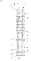
- a switch 3 is shown schematically in plan view.
- the switch 3 is divided into switch tip 16, switch center 17 and switch end 18.
- Stock rails 7 and tongue rails 8 are shown.
- the right-hand side 6 of the switch 3 is assigned from the tongue tip 16 in the direction of view (reference number 2) to the switch end 18.
- On the left-hand side 5 of the switch 3 is the off-lying tongue rail 11 and on the right-hand side 6 of the points 3, the adjacent switch rail 10 is shown.
- a switch temperature sensor 28 is arranged on a stock rail 7, here on the left side 5 of the switch 3.
- switch segment switch tip 34 In the area of the switch tip 16, for example, there is a switch segment switch tip 34, in the area of the switch center 17 there is a switch segment switch center 35 and in the area of switch end 18 a switch segment switch end 36 is arranged for the left side 5 of the switch 3 and the right side 6 of the switch 3 .
- the point temperature sensor 28 is located at the point tip on the right side 6 of the point 3 or on the left side 5 of the point 3.
- the support lugs 13 present in the area of the support lugs are also shown; these serve to support the tongue rail 8 on the side of the adjacent tongue rail 10 compared to the stock rail 7 when the train travels over the point rail 8.
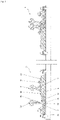
- figure 1 is a schematic sectional view of the switch 3 from figure 0 shown on the switch segment switch tip 34 with the left side 5 of the switch 3 and the right side 6 of the switch 3.
- the tongue rail 11 lying away and on the right-hand side 6 of the switch 3 the adjacent tongue rail 12 is shown.
- the functionally relevant points 19 of the switch 3 in winter are shown on the left side 6 of the switch 3 by the evaluation points (37 to 43.
- the points heating 1 according to the invention should make these functionally relevant points 19, characterized by the evaluation points 37 to 43, in winter at negative ambient temperatures be heated in such a way that the snow or ice on it is melted.
- the evaluation points 37 to 43 on the left side 5 and on the right side (69) of the switch of switch 3 are the evaluation points foot stock rail 37, web stock rail 38, Head stock rail 39, foot tongue rail 40, head tongue rail 41, middle slide chair plate 42 and outer slide chair plate 43, which are each represented by nodes K of the heating network 26, 27 and the functionally relevant points 19 on the right-hand side 6 of the points 3 and the left side 5 of the switch 3.
- the switch temperature sensor 28 is on the left stock rail 7 between two Thresholds 24 are arranged and the real switch temperatures Tw recorded with them on the stock rail 7 left side 5 of the switch 3 can be compared with the calculated optimal switch temperatures at this function-relevant point 19 with the calculated optimal switch temperatures T W-op and corrected if there are differences.
- the travel path of the switch 3 is constantly changed by adjusting the tongue rails 8 by the left side 5 of the switch 3 and the right side 6 of the switch 3 the tongue rail 8 is alternately on or off the stock rail 7.
- the detection of the position of the tongue rails 8 on or off the stock rails 7 is carried out by evaluating the calculated optimal switch temperatures T W-op at the respective assessment points of the functionally relevant points 19, preferably at the head-switch rail assessment point 41.
- the points are fitted with a heating device 14 on the stock rail foot heated.
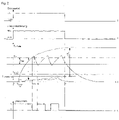
- the heating is switched off with two-point control and after a slight overshoot of the real point temperature due to the mass of the rail up to time t 7 , it cools down to time t 8 and the heating current (I N ) is increased switched on again at this time.
- the time from t 1 to t 6 is referred to as the heating-up time t A and the time from t 6 to t 9 as the control time.
- the slide chair plate that is away from the heating device and is not provided with the heating device 14 is only heated very slowly and at time t 6 has a very low real point temperature T W-outside GL, which is well below the set point temperature.
- the heating current for all heating devices of the switch is switched off by the parameterized hysteresis of, for example, 4° C., so that cooling also starts on the slide chair plate.
- the point temperature difference ⁇ T W at time t 6 between the base of the stock rails and the slide chair platform is very large. At an ambient temperature of -15 °C, for example, this point temperature difference ⁇ T W is so great that the point temperature on the outside of the slide chair plate is less than 0 °C even after a very long time and the points can accumulate ice and freeze solid at this point.
- FIG 2 shows the time course of the heating current I N when the heating request is ON, which switches on and off during operation between zero and the maximum heating current I N depending on the point temperature at the foot of the stock rail switched off, resulting in power peaks between zero and rated current.
- the temperatures at the points temperature sensor (28) are measured and used to evaluate or correct the calculated optimal points temperatures.
- FIG 3 is for switch segment of the switch 3 a heating network 26 according to the invention for the left side 5 of the switch 3 and partially an analogous heating network 27 for the right side 6 of the switch 3 according to a sectional view figure 1 shown at any area of the switch 3, which are connected via the node K ambient temperature K TU .
- Heating devices 14, 29 are arranged, for example, on the inside of the stock rail 7 on the stock rail foot.
- the heating network 26 for the left side 5 of the switch 3 and the heating network 27 for the right side 6 of the switch 3 are based on a sectional view along the slide chair plate 9 on the left side 5 of the switch 3 and the opposite slide chair plate 9 on the right side 6 of the switch 3 and the cross-section of the stock rail 7 and the tongue rail 8 on the left side 5 of the switch 3 and stock rail 7 and tongue rail 8 on the right side 6 of the switch 3 at any switch area 4 of the switch 3 with symbols for heating device 29, symbols for heat radiation 30 , symbols convection 31, symbols heat conduction 33 and symbols heat storage 32 between the functionally relevant points 19 of the switch 3, which are represented by node K.
- the heat network 26 on the left side 5 of the switch 3 there is a heat network between the ambient temperature Tu, which is represented by node K ambient temperature K TU , and functionally relevant points 19, which are also represented by node K, which is calculated using known rules .
- the nodes K for the functionally relevant points 19 of the switch 3 for the heating network 26 for the left side 5 of the switch 3 and for the heating network 27 for the right side 6 of the switch 3 are the same and correspond to the evaluation points 37 to 43, but the power losses of the adjacent tongue rail 10 and remote tongue rail 11 are different.
- the table below shows the relationship between the functionally relevant points 19, the corresponding nodes K and the required switch temperature T W , which is calculated at the respective node K with the designation T W-op and is evaluated in a separate program for the heating network 26 for the left-hand side 5 of the switch 3.
- the heating network 27 for the right-hand side 6 of the switch 3 is analogous to this and connected via the node K ambient temperature K TU .
- the points segment is broken down into sections and each section is represented by a node K, which indicates the mean points temperature Tw of the associated section.
- the size of the sections or the number of nodes K depend on the required replication accuracy.
- the power losses and thermal resistances and thermal capacities are calculated from the material properties, the geometric parameters and the prevailing loads from the heating current I N and the environment.
- the connection of the nodes K by means of resistors, capacitors and voltage sources results in a network that can be solved numerically with the help of the node and mesh theorem. If the power balance is created for a node K, Kirchhoff 's theorem (node theorem) applies.
- P S + P K + P L P lei + P c
- the heating-up time t A is shown first. If the conditions for heating operation are met, e.g. snow, the heating is activated via a heating request signal from the control device and the heating devices 14 on the stock rails 7 are switched on and, after the set points temperature T set point has been reached, controlled via two-point control with hysteresis and thus the parts of the Soft 3 heated.
- the tongue rails 8 and slide chair plates 9, which are not provided with a heating device 14, are heated by thermal conduction and radiation.
- the heating-up time t A begins with the activation of the heating and ends when the set point temperature T set point is reached at a point temperature sensor 28 which is arranged under the foot on a stock rail 7 .
- the duration of the heating-up time t A depends on many factors and should be calculated and monitored to ensure availability, and appropriate measures initiated if necessary.
- the heating time t A is calculated for at least one switch segment for the left side 5 of the switch 3 and the right side 6 of the switch 3 in several steps, taking into account the times in which the switch segment is heated up to the minimum switch temperature T W-min of the switch 3, snow melt, evaporation of water and then up to the set point temperature T set point 3 takes place.
- FIG 4 is the course over time of the switch temperature T W-Fu-Ba of the switch 3 at the foot of a stock rail 7 and the switch temperature T W-GL-au outside of the switch 3 of the slide chair plate 9 on one side, e.g. the left side 5 of the switch 3, shown.
- the individual time periods are explained below. Due to the mass inertia, there is a dead time t T from t 1 to t 2 during operation. The dead time t T is calculated.
- the heating-up time t A is the time until the melting temperature of snow is reached by time t 2.1 . From the time t 2 the switch 3 is heated up to the melting temperature Ts, which is reached at the time t 2.1 .
- the time taken to melt the amount of snow that has fallen or is required for the specific project consists of two partial times t A2 and t A3 .
- time t A2 the time for melting the amount of snow is calculated from time t A1 and during time t A3 the amount of snow fallen during time t A2 is calculated.
- the calculation of the melting capacity per hour is based on the amount of snow hs and the horizontal surfaces of the switch segment and an average density of snow , e.g average specific heat of fusion of e.g. 335 kJ/Kg. Snow starts to melt at 0°C.
- the specific power is therefore calculated, for example, at a point temperature of 0 °C on the stock rail 7, taking into account the required optimum specific power of the heating device 14 to maintain the melting temperature of the stock rail 7, which corresponds to the sum of the power losses at this melting temperature.
- the total heating-up time t A2 plus t ANH3 for melting the entire amount of snow from the heating-up time t A1 and the heating-up time t A2 is calculated from the product of the melting capacity per hour and the sum of time t ANH1 and time t ANH2 and dead time t T .
- the heating-up time t A4 begins at time t 2.3 and ends when the switch temperature sensor 28 reaches the target rail temperature T set point 3.
- the heating-up time t A4 is calculated using the thermal resistance R th and thermal capacity C th determined with the heat network model and the power loss based on the chronological progression starting from the melting temperature until the set point temperature is reached analogous to point 1 with the corresponding absolute set point temperature from the difference between the set point temperature and the melting temperature.
- the heating-up time t A5 the snow from the heating-up time t A4 is melted.
- the calculation is analogous to the heating-up time t A2 or t A3 .
- the entire heating-up time t A lasts from time t 1 to t 7 and is determined and evaluated from the sum of dead time and heating-up times t A1 to t A5 .
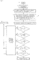
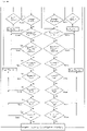
- FIG 6 is the program sequence for verifying the function of the point heating 1 according to the invention as a function of the minimum ambient temperature T u , the existing specific power of the heating device P, the set point temperature T set point 3 at maximum wind speed v max for the rail profile R of the point 3 and a possible maximum Amount of snow per hour h S-max and the location of the heating devices 14 on the stock rail 7 and/or the tongue rail 8 and/or the slide chair plate 9.
- the limit of the function of the points heating 1 according to the invention and thus the availability of the points 3 in winter for a standard point heating 1 can be determined and evaluated, even when operating with the current air temperature, amount of snow per hour and wind speed v.
- the present invention specifies a method in which the heat network model according to the invention changes the set point temperature and/or the specific power of at least one heating device 14 by comparing the calculated points temperatures with parameterized minimum points temperatures.
- the heat network model according to the invention verifies the calculated points temperatures by means of a comparison with points temperatures detected by a points temperature sensor 28 by correcting the convection power and/or the radiation power.
- the heating network model according to the invention also generates a warning message in the control device before the operating limit is exceeded for a control system and on site.
- the heating network determines the heating-up time before and during operation and activates an additional preheating heating regime via the control device if, depending on the forecast environmental conditions from the weather service, the maximum amount of snow is exceeded during the heating-up time and/or the amount of snow is not melted.
Landscapes
- Engineering & Computer Science (AREA)
- Mechanical Engineering (AREA)
- Architecture (AREA)
- Civil Engineering (AREA)
- Structural Engineering (AREA)
- Control Of Resistance Heating (AREA)
- Train Traffic Observation, Control, And Security (AREA)
- Central Heating Systems (AREA)
Claims (11)
- Procédé de commande et de régulation d'un chauffage d'aiguillage (1), dans lequel le chauffage d'aiguillage (1) présente au moins un dispositif de chauffage (14) disposé sur au moins un aiguillage (3), au moins un capteur de température d'aiguillage (28) sur l'au moins un aiguillage (3), au moins une distribution d'énergie pourvue d'au moins une sortie de chauffage par aiguillage (3) et au moins un dispositif de commande pour la commande et la régulation de la température d'aiguillage, au moins un boîtier de raccordement disposé à l'écart de l'aiguillage (3), qui présente au moins un appareil de commutation, qui est relié aux dispositifs de chauffage (14) de l'aiguillage (3) par le biais de conduites, ainsi que des moyens de mesure pour la détection dans le temps du courant de fonctionnement, de la tension et de la résistance d'isolation et des moyens de limitation de la puissance maximum, au moins un moyen de communication, qui est disposé dans le boîtier de raccordement et relié au dispositif de commande, et au moins un capteur de précipitations pour la détection du type de précipitation et de la quantité de précipitation, qui est relié au dispositif de commande, comprenant les étapes de :a) définition d'au moins un segment d'aiguillage pour le côté gauche (5) de l'au moins un aiguillage (3) et/ou pour le côté droit (6) de l'au moins un aiguillage (3) avec une longueur spécifique, dans lequel le segment d'aiguillage de l'au moins un aiguillage (3) présente une contre-aiguille (7), une lame d'aiguille (8), une plaque de coussinet de glissement (9) et au moins un dispositif de chauffage (14), et décomposition de l'au moins un segment d'aiguillage en différentes sections avec respectivement au moins un premier nœud, qui correspond au moins à un endroit important pour le fonctionnement (19) du segment d'aiguillage de l'au moins un aiguillage (3) en hiver, dans lequel l'endroit important pour le fonctionnement (19) présente au moins un point d'évaluation (37, 38, 39, 40, 41, 42, 43),
dans lequel l'au moins un segment d'aiguillage représente thermodynamiquement de manière représentative l'au moins un aiguillage (3), dans lequel l'au moins un segment d'aiguillage est disposé à proximité de l'au moins un capteur de température d'aiguillage (28),b) formation d'un réseau de chaleur (26) pour l'au moins un segment d'aiguillage pour le côté gauche (5) de l'au moins un aiguillage (3) et/ou formation d'un réseau de chaleur (27) pour l'au moins un segment d'aiguillage pour le côté droit (6) de l'au moins un aiguillage (3), dans lequel le réseau de chaleur (26, 27) présente des éléments de production de chaleur, des éléments de transmission de chaleur et des accumulateurs de chaleur (32), et association du respectivement au moins premier nœud (K) des sections respectives de l'au moins un segment d'aiguillage à au moins un point d'évaluation (37, 38, 39, 40, 41,42,43),
dans lequel tous les nœuds (K) des différentes sections sont reliés au réseau de chaleur (26, 27) par le biais de mailles de sorte que la différence de toutes les températures affectées d'un signe est égale à zéro.c) calcul de l'évolution dans le temps d'une puissance spécifique optimale (Pop) de l'au moins un segment d'aiguillage et de la température d'aiguillage optimale (Top) respective sur l'au moins un premier nœud du chauffage d'aiguillage (1) sur l'au moins un segment d'aiguillage par le biais d'une balance de puissance conformément à un jeu de nœuds, et lors du fonctionnement activation de cette puissance spécifique optimale (Pop) sur le dispositif de chauffage (14) afférant au moyen du produit de la puissance spécifique réelle (P) du dispositif de chauffage (14), qui correspond à la puissance spécifique maximum, et d'un rapport de puissance, dans lequel le rapport de puissance correspond de manière variable entre 25 % et 100 % de la puissance spécifique réelle (P),d) détection de l'évolution dans le temps de la température d'aiguillage réelle (Tw) sur l'au moins un segment d'aiguillage avec l'au moins un capteur de température d'aiguillage (28) et correction de la température d'aiguillage calculée sur un de l'au moins premier nœud de l'au moins un segment d'aiguillage par le biais de la puissance chaleur de convection (PK) lorsque la température d'aiguillage calculée est supérieure à la température d'aiguillage réelle (Tw) ou de la puissance chaleur de rayonnement (PSt) du réseau de chaleur lorsque la température d'aiguillage calculée est inférieure à la température d'aiguillage réelle,e) calcul de la température finale d'aiguillage sur au moins un deuxième nœud de l'au moins un segment d'aiguillage et comparaison de la température finale d'aiguillage calculée avec une température minimum d'aiguillage (Tmin) paramétrée pour cet au moins un deuxième nœud,
dans lequel lorsque la température minimum d'aiguillage (Tmin) de l'aiguillage (3) n'est pas atteinte, une température de consigne d'aiguillage (TSoll) paramétrable est augmentée d'un facteur de correction de la température de consigne d'aiguillage (y) jusqu'à ce que la température finale d'aiguillage calculée respective de l'aiguillage (3) corresponde au moins à la température minimum d'aiguillage (Tmin) de l'aiguillage (3),f) calcul du temps de préchauffage (tA) pour le réchauffement de l'au moins un segment d'aiguillage jusqu'à la température de consigne d'aiguillage (TSoll) paramétrable de l'aiguillage (3) et évaluation du temps de préchauffage (tA) calculé pour la température de consigne d'aiguillage (TSoll) paramétrable, dans lequel dans le cas d'un déficit, la puissance spécifique optimale (Pop) est augmentée et dans le cas d'un excédent, la puissance spécifique optimale (Pop) est diminuée,g) calcul du temps de préchauffage (tA) pour le réchauffement de l'au moins un segment d'aiguillage jusqu'à la température minimum d'aiguillage (Tmin) paramétrable de l'aiguillage (3) et évaluation de la puissance spécifique nécessaire (Perf) à partir de la puissance de maintien (Perh) et de la puissance de fonte (Psm) pour la neige (hs) tombée jusque-là avec la puissance spécifique (P) pour la température minimum d'aiguillage (Tmin) paramétrable,
dans lequel dans le cas d'un déficit, la puissance spécifique optimale (Pop) est augmentée ou un message « la quantité de neige tombée est trop importante et n'est pas fondue » est généré. - Procédé selon la revendication 1, comprenant en outre avant le fonctionnement par une demande de chauffage, l'étape de
h) calcul de la puissance de fonte spécifique (P) pour la quantité de neige calculée sur le segment d'aiguillage pendant le temps de préchauffage (tA) à partir d'une hauteur de neige signalée par unité de temps et calcul de la puissance de maintien spécifique (Perh) pour le maintien de la température de fonte (Psm) sur le segment d'aiguillage et comparaison de la somme de celles-ci avec la puissance spécifique réelle (P) du dispositif de chauffage (14) et, lorsque la puissance spécifique réelle (P) du dispositif de chauffage (14) est inférieure, activation du chauffage d'aiguillage (1) avec une deuxième température de consigne d'aiguillage (TSoll-Vor), qui est aussi grande que lors du fonctionnement, la puissance spécifique (P) du dispositif de chauffage (14) est au moins égale à la somme de la puissance de fonte (Psm) et de la puissance de maintien (Perh) spécifiques. - Procédé selon la revendication 1 ou 2, dans lequelles éléments de production de chaleur comprennent la puissance spécifique (P) de l'au moins un dispositif de chauffage (14) avec un accumulateur de chaleur du segment d'aiguillage et une transmission de chaleur par rayonnement thermique et/oules éléments de transmission de chaleur comprennent des résistances thermiques sur l'aiguillage (3) à partir des propriétés des substances, des grandeurs géométriques et des sollicitations prédominantes par la transmission de chaleur et l'environnement sur l'au moins un segment d'aiguillage.
- Procédé selon l'une quelconque des revendications 1 à 3, dans lequel dans l'étape f)le temps de préchauffage (tA) pour le réchauffement de l'au moins un segment d'aiguillage est calculé à partir de la somme des différents temps de chauffe pour l'au moins un segment d'aiguillage pour son réchauffement, pour la fonte de la neige et pour l'évaporation de l'eau sur celui-ci, et/oule temps de préchauffage (tA) est augmenté par augmentation du rapport de puissance et/ou commutation du mode de régulation au mode continu et/ou est diminué par diminution du rapport de puissance.
- Procédé selon l'une quelconque des revendications 1 à 4, comprenant en outre lorsque le chauffage est activé, les étapes dei) calcul d'une puissance de fonte (Psm) pour la neige (hS) tombée dans une période de temps paramétrable et comparaison de cette puissance de fonte avec la différence entre la puissance spécifique (P) et une puissance de maintien (Perh) calculée, dans lequel dans le cas d'un déficit de la puissance spécifique, la puissance (Perf) est augmentée et/ou un chauffage continu est lancé et/ou un premier message d'avertissement est émis,
et/ouj) comparaison du temps de préchauffage (tA) calculé avec un temps de préchauffage maximum paramétré, dans lequel dans le cas d'un déficit de la puissance spécifique, la puissance est augmentée et/ou un chauffage continu est lancé et/ou un deuxième message d'avertissement est émis,
et/ouk) calcul de la hauteur de neige (hs) à partir de la différence entre la hauteur de neige tombée et la hauteur de neige fondue par unité de temps et comparaison de la hauteur de neige calculée avec une hauteur de neige admissible maximum paramétrable, dans lequel dans le cas d'un déficit de la puissance spécifique, la puissance est augmentée et/ou un chauffage continu est lancé et/ou un troisième message d'avertissement est émis. - Procédé selon l'une quelconque des revendications 1 à 5, dans lequel le calcul du temps de préchauffage (tA) dans l'étape f) comprend les sous-étapes de :f1) calcul du temps mort (tT) pour l'au moins un segment d'aiguillage à partir de l'évolution dans le temps de la température d'aiguillage (Tw) de l'aiguillage (3) pour la puissance spécifique optimale (Pop) ou la puissance spécifique réelle (P),f2) calcul du temps tA1 pour le réchauffement de l'au moins un segment d'aiguillage de la température d'aiguillage du rail froid de l'aiguillage (3) et de la température de fonte (Ts) jusqu'à la température minimum d'aiguillage (Tmin) sur au moins un nœud,f3) calcul du temps tA2 pour la fonte de la quantité de neige pendant l'étape f2) à partir de la différence de la puissance spécifique présente déduction faite de la puissance (Perh) pour le maintien de la température minimum d'aiguillage (Tmin) de l'au moins un segment d'aiguillage,f4) calcul du temps tA3 pour la fonte de la neige tombée pendant l'étape f3) à partir de la différence de la puissance spécifique présente déduction faite de la puissance (Perh) pour le maintien de la température minimum d'aiguillage (Tmin) de l'au moins un segment d'aiguillage,f5) calcul du temps tA4 pour le réchauffement de l'au moins un segment d'aiguillage à partir de la différence de la température minimum d'aiguillage jusqu'à la température de consigne d'aiguillage (Tsoll) sur les nœuds avec le capteur de température d'aiguillage (28) de l'aiguillage (3),f6) calcul du temps tA5 pour la fonte de la neige tombée pendant l'étape f5) à partir de la différence de la puissance spécifique présente (P) déduction faite de la puissance (Perh) pour le maintien de la température minimum d'aiguillage (Tmin) de l'au moins un segment d'aiguillage.
- Procédé selon l'une quelconque des revendications 1 à 6, comprenant en outre une détermination de la limite de fonctionnement en rapport avec la température ambiante (GW-Tu) du chauffage d'aiguillage (1), comprenant- le calcul des températures finales d'aiguillage optionnelles (Top) sur deux nœuds spécifiques de l'au moins un segment d'aiguillage, lesquels correspondent à la contre-aiguille de tête (20) et à la lame d'aiguille de tête (21) en tant qu'endroits importants pour le fonctionnement (19) de l'au moins un aiguillage (3), dans lequel les températures d'aiguillage calculées pour la contre-aiguille de tête (20) et la lame d'aiguille de tête (21) sont soustraites de la température minimum d'aiguillage (Tmin) et la plus petite d'entre elles correspond à la température ambiante limite de fonctionnement.
- Procédé selon l'une quelconque des revendications 1 à 7, comprenant en outre une détermination de la limite de fonctionnement en rapport avec la quantité de neige (GW-hs) du chauffage d'aiguillage (1), comprenant- le calcul d'une puissance de maintien spécifique (Perh) pour la température minimum d'aiguillage (Tmin) de l'aiguillage (3), à laquelle s'ajoute une tolérance de température minimum d'aiguillage □Tmin, sur le pied de la contre-aiguille, d'une puissance de fonte (Psm) pour la quantité de neige maximum ou la quantité de neige (hs) détectée jusque-là ainsi que d'une puissance d'évaporation (Pv) pour l'eau de fonte, et comparaison de la somme de ces éléments avec la puissance spécifique nécessaire (Perf) du dispositif de chauffage (14) de l'au moins un segment d'aiguillage, lorsque la puissance spécifique nécessaire (P) du dispositif de chauffage est inférieure à la somme de la puissance de maintien (Perh) et de la puissance de fonte (Psm) et de la puissance d'évaporation et que la limite de fonctionnement en rapport avec la hauteur de neige est dépassée.
- Procédé selon l'une quelconque des revendications 1 à 8, comprenant en outre un dimensionnement spécifique au projet des dispositifs de chauffage (14) et de leur puissance spécifique nécessaire (Perf), comprenant- le calcul d'une puissance spécifique (P) du dispositif de chauffage pour atteindre une température de consigne d'aiguillage (Tsoll) de l'aiguillage (3) à l'emplacement du capteur de température d'aiguillage (28) et une température d'aiguillage minimum Tw-min de l'aiguillage (3) sur au moins une contre-aiguille de tête (20) et/ou une lame d'aiguille de tête (21) pour l'au moins un segment d'aiguillage par calcul de la somme de la conduction thermique, du rayonnement et de la convection dans l'environnement, de la capacité thermique et de la chaleur latente en cas de neige et de pluie, pour les valeurs limites de fonctionnement présentes de la température ambiante minimum (Tu), du profil de rail, de la vitesse de vent maximum (vmax) et de la hauteur de neige maximum par heure, et- l'augmentation de la puissance spécifique nécessaire (Perf), lorsque la puissance spécifique réelle (P) calculée est inférieure à la puissance spécifique, qui correspond à la puissance de fonte nécessaire (Psm) dans le temps de préchauffage (tA), qui est calculé à partir de la température ambiante minimum jusqu'à ce qu'une température de rail d'au moins 0°C soit atteinte, pour la quantité de neige, qui résulte du produit du temps de préchauffage (tA) et de la hauteur de neige (hs) par heure, et à la puissance d'évaporation (Pv) de l'eau de fonte résiduelle et à la puissance de maintien spécifique nécessaire (Perf) pour une température de rail de 0°C aux endroits importants pour le fonctionnement (19) de l'au moins un segment d'aiguillage.
- Procédé selon l'une quelconque des revendications 1 à 9, dans lequel- lors du fonctionnement du chauffage d'aiguillage (1), un réglage de la puissance spécifique optimale pour les dispositifs de chauffage (14), qui correspond au produit de la puissance spécifique et d'un rapport de puissance de 25 % à 100 %, a lieu par le biais des appareils de commutation respectifs pour la mise en circuit et la mise hors circuit des dispositifs de chauffage (14) par modification de la durée d'allumage ou de la fréquence ou de la largeur d'impulsion ou par commande par train d'ondes ou par fonctionnement en groupement,
et/ou- le rapport de puissance est entre 25 % et 100 %,
dans lequel lors du fonctionnement du chauffage d'aiguillage (1), la puissance spécifique (P) du côté gauche (5) de l'aiguillage (3) et du côté droit (6) de l'aiguillage (3) correspond au maximum à la valeur moyenne et/ou au méridien de la puissance spécifique du dispositif de chauffage (14),
et/ou- lors du fonctionnement du chauffage d'aiguillage (1), la puissance spécifique calculée (Pop) pour le côté gauche (5) de l'aiguillage (3) et le côté droit (6) de l'aiguillage (3) correspond au maximum à la puissance spécifique (P) des dispositifs de chauffage (14),
ou une différence de puissance spécifique pour le côté gauche (5) de l'aiguillage (3) ou le côté droit (6) de l'aiguillage (3) est calculée à partir de la différence de la puissance spécifique (P) des dispositifs de chauffage (14) déduction faite de la puissance spécifique calculée (Pop) et en cas de différence de puissance spécifique positive du côté gauche (5) de l'aiguillage (3) ou du côté droit (6) de l'aiguillage (3), cette différence de puissance spécifique est mise à la disposition de l'autre côté respectif de l'aiguillage (3) en plus de la puissance spécifique (P) du dispositif de chauffage (14) de sorte qu'une évolution régulière dans le temps des températures de rail de l'aiguillage (3) sur le côté gauche (5) de l'aiguillage (3) et sur le côté droit (6) de l'aiguillage (3) a lieu aux endroits importants pour le fonctionnement (19) de l'aiguillage (3). - Dispositif de commande pour la commande et la régulation d'une température d'aiguillage d'un chauffage d'aiguillage (1) aménagé pour la réalisation du procédé selon l'une quelconque des revendications 1 à 10, dans lequel le chauffage d'aiguillage (1) présente au moins un dispositif de chauffage (14) disposé sur au moins un aiguillage (3), au moins un capteur de température d'aiguillage (28) sur l'au moins un aiguillage (3) et au moins une distribution d'énergie pourvue d'au moins une sortie de chauffage par aiguillage (3), le dispositif de commande comprenant :- une CPU pour le calcul des températures d'aiguillage de l'aiguillage (3) pour au moins un segment d'aiguillage, qui est relié au dispositif de commande par le biais de moyens de communication,- au moins un boîtier de raccordement disposé à l'écart de l'aiguillage (3), qui présente au moins un appareil de commutation, qui est relié aux dispositifs de chauffage (14) de l'aiguillage (3) par le biais de conduites, ainsi que des moyens de mesure pour la détection dans le temps du courant de fonctionnement, de la tension et de la résistance d'isolation et des moyens de limitation de la puissance maximum,- au moins un moyen de communication, qui est disposé dans le boîtier de raccordement et relié au dispositif de commande,- au moins un capteur de précipitations pour la détection du type de précipitation et de la quantité de précipitation, qui est relié au dispositif de commande.
Applications Claiming Priority (2)
| Application Number | Priority Date | Filing Date | Title |
|---|---|---|---|
| DE102018007263.1A DE102018007263B4 (de) | 2018-09-16 | 2018-09-16 | Verfahren und Einrichtung zur Steuerung und Regelung einer Weichenheizung |
| PCT/IB2019/057768 WO2020053842A2 (fr) | 2018-09-16 | 2019-09-16 | Procédé et dispositif pour commander et réguler un chauffage d'aiguillage |
Publications (2)
| Publication Number | Publication Date |
|---|---|
| EP3850154A2 EP3850154A2 (fr) | 2021-07-21 |
| EP3850154B1 true EP3850154B1 (fr) | 2022-11-30 |
Family
ID=68242783
Family Applications (1)
| Application Number | Title | Priority Date | Filing Date |
|---|---|---|---|
| EP19787440.7A Active EP3850154B1 (fr) | 2018-09-16 | 2019-09-16 | Procédé et dispositif de contrôle pour commander et réguler un chauffage d'aiguillage |
Country Status (5)
| Country | Link |
|---|---|
| EP (1) | EP3850154B1 (fr) |
| CN (1) | CN112823224B (fr) |
| DE (1) | DE102018007263B4 (fr) |
| DK (1) | DK3850154T3 (fr) |
| WO (1) | WO2020053842A2 (fr) |
Families Citing this family (4)
| Publication number | Priority date | Publication date | Assignee | Title |
|---|---|---|---|---|
| DE102020129223B3 (de) | 2020-11-05 | 2022-04-21 | Esa Elektroschaltanlagen Grimma Gmbh | Verfahren und Einrichtung zum Beheizen von Fahrwegelementen |
| RU205831U1 (ru) * | 2021-04-30 | 2021-08-11 | Общество с ограниченной ответственностью "Информационные технологии" (ООО "ИнфоТех") | Стрелочный перевод с электрообогревом |
| CH720038A1 (de) | 2022-09-14 | 2024-03-28 | Backer Elc Ag | Weichenheizung mit integrierter Steuerung. |
| CN116289350B (zh) * | 2023-05-10 | 2023-10-24 | 华兴云通(北京)科技有限公司 | 一种道岔加热设备防护方法及装置 |
Family Cites Families (25)
| Publication number | Priority date | Publication date | Assignee | Title |
|---|---|---|---|---|
| US4391425A (en) * | 1978-03-20 | 1983-07-05 | Keep Jr Henry | Railroad switch heater |
| JPH05148801A (ja) * | 1991-11-29 | 1993-06-15 | Central Japan Railway Co | 鉄道ポイント融雪装置 |
| CN2200004Y (zh) * | 1994-06-25 | 1995-06-07 | 鞍山钢铁公司 | 铁路道岔电热融雪装置 |
| DE19742085B4 (de) * | 1997-09-24 | 2009-03-12 | Pintsch Aben B.V. | Weichenheizungssystem |
| KR100358407B1 (ko) * | 2000-08-04 | 2002-10-25 | (주)아비즈코퍼레이션 | 전철기용 텅레일부 융설장치 |
| EP1195467A3 (fr) * | 2000-10-05 | 2003-05-14 | Rail Product Design Ltd. | Système de chauffage pour coeur de voie |
| KR20040025497A (ko) * | 2002-09-19 | 2004-03-24 | 주식회사 대신상역엔지니어링 | 분기기 융설장치 및 “터치”식 통신제어 그 장치 |
| SE531380C2 (sv) * | 2007-05-04 | 2009-03-17 | Swedesafe Marketing Ab | Värmesystem |
| CN101311412A (zh) * | 2007-05-22 | 2008-11-26 | 上海奇谋能源技术开发有限公司 | 一种快速融化铁路道叉冰雪的方法及装置 |
| EP2265762A1 (fr) * | 2009-04-07 | 2010-12-29 | EAN Elektroschaltanlagen Grimma GmbH | Procede et dispositif de gestion energetique pour chauffages d'aiguilles electriques |
| CN101629402B (zh) * | 2009-08-07 | 2010-12-01 | 孙健 | 铁路道岔快速融雪装置 |
| RU97386U1 (ru) * | 2010-04-22 | 2010-09-10 | Общество с ограниченной ответственностью "КТН" (ООО "КТН") | Устройство для очистки стрелочного перевода от снега и льда путем электрообогрева "сэит-04" |
| CN201924317U (zh) * | 2010-12-17 | 2011-08-10 | 嘉纳尔科技(北京)有限公司 | 铁路道岔的除冰系统 |
| CA2787215C (fr) * | 2011-08-16 | 2019-12-31 | Railway Equipment Company, Inc. | Commutateur de chauffage a charge equilibree |
| CN102444058B (zh) * | 2011-08-30 | 2017-03-15 | 孙健 | 辐射式铁路道岔融冰除雪系统 |
| CN202374474U (zh) * | 2011-12-27 | 2012-08-08 | 彭建邦 | 一种可变功率道岔融雪装置 |
| DE102012215539A1 (de) * | 2012-08-31 | 2014-03-06 | Siemens Aktiengesellschaft | Vorrichtung zur Überwachung der Funktionsfähigkeit von Heizelementen einer beheizbaren Weiche |
| EP2720513B1 (fr) * | 2012-10-15 | 2015-04-22 | IFF GmbH | Dispositif inductif de chauffage d'aiguille et/ou de rail |
| CN104074165A (zh) * | 2013-03-27 | 2014-10-01 | 陈萌 | 一种道岔融雪控制系统 |
| EP3169138A1 (fr) * | 2015-11-16 | 2017-05-17 | IFF GmbH | Dispositif de chauffage inductif comprenant un dispositif de reglage de temperature a niveaux multiples adaptatif |
| DE102016011117A1 (de) * | 2016-09-17 | 2018-03-22 | Ean Elektroschaltanlagen Gmbh | Verfahren und Einrichtung zum Energiemanagement einer elektrischen Weichenheizungsanlage |
| CN106638443A (zh) * | 2016-12-30 | 2017-05-10 | 河南辉煌科技股份有限公司 | 智能铁路道岔融雪系统 |
| CN208283577U (zh) * | 2017-10-19 | 2018-12-25 | 西安铁路信号有限责任公司 | 一种用于道岔融雪检测的雨雪检测传感器 |
| CN207397032U (zh) * | 2017-10-23 | 2018-05-22 | 北京国铁路阳技术有限公司 | 一种铁路道岔融雪设备上使用的智能功率控制装置 |
| CN107815933B (zh) * | 2017-10-23 | 2019-12-10 | 华东交通大学 | 一种铁路道岔尖轨与基本轨冰、雪检测与融化装置 |
-
2018
- 2018-09-16 DE DE102018007263.1A patent/DE102018007263B4/de active Active
-
2019
- 2019-09-16 EP EP19787440.7A patent/EP3850154B1/fr active Active
- 2019-09-16 WO PCT/IB2019/057768 patent/WO2020053842A2/fr active Application Filing
- 2019-09-16 DK DK19787440.7T patent/DK3850154T3/da active
- 2019-09-16 CN CN201980060364.XA patent/CN112823224B/zh active Active
Also Published As
| Publication number | Publication date |
|---|---|
| CN112823224B (zh) | 2022-11-08 |
| WO2020053842A2 (fr) | 2020-03-19 |
| EP3850154A2 (fr) | 2021-07-21 |
| DE102018007263B4 (de) | 2023-03-30 |
| CN112823224A (zh) | 2021-05-18 |
| DE102018007263A1 (de) | 2020-03-19 |
| WO2020053842A3 (fr) | 2020-05-07 |
| DK3850154T3 (da) | 2023-02-20 |
Similar Documents
| Publication | Publication Date | Title |
|---|---|---|
| EP3850154B1 (fr) | Procédé et dispositif de contrôle pour commander et réguler un chauffage d'aiguillage | |
| EP2689466B1 (fr) | Procédé et appareil pour determiner la puissance fournie par un système photovoltaïque | |
| EP3048687B1 (fr) | Procede de commande d'un reseau de distribution d'energie electrique | |
| EP3391455A1 (fr) | Commande de durée de vie d'un accumulateur d'énergie | |
| EP3645865B1 (fr) | Système éolien et procédé de régulation d'une installation éolienne | |
| EP3107174A1 (fr) | Procédé, dispositif de commande et système de fonctionnement d'un sous-réseau d'un réseau de distribution d'énergie | |
| DE2059977A1 (de) | Verfahren und Vorrichtung zur Regelung eines Brammen-Nachwaermofens | |
| DE102015101738A1 (de) | Verfahren zum Betrieb einer Energieerzeugungsanlage und Energieerzeugungsanlage | |
| DE112018005230T5 (de) | Trendfunktionen zum vorhersagen der intaktheit von elektrischen energieanlagen | |
| EP2843788A2 (fr) | Procédé destiné au fonctionnement d'un système de centrale | |
| EP2265762A1 (fr) | Procede et dispositif de gestion energetique pour chauffages d'aiguilles electriques | |
| DE10257425A1 (de) | Einrichtung und Verfahren zum Schutz eines elektrischen Spannungsversorgungssystems | |
| DE3620929A1 (de) | Verfahren und einrichtung zur regelung mindestens einer heizung | |
| EP3839253B1 (fr) | Procédé de détermination d'une production d'énergie d'une éolienne | |
| WO2010142727A1 (fr) | Procédé de régulation d'un chauffage d'aiguilles de rail | |
| DE102015209452A1 (de) | Verfahren zum Betrieb einer Batterie | |
| DE2316341A1 (de) | Verfahren zum stufenlosen verteilen elektrischer energie | |
| EP1674667A1 (fr) | Procédé et dispositif pour le préchauffage d'une turbine à vapeur | |
| WO2021047907A1 (fr) | Procédé de régulation de la température d'une armoire de commande pour dispositifs de commutation à moyenne et haute tension | |
| EP3340413B1 (fr) | Procédé, dispositif de commande et système de détermination de données d'état d'un réseau d'alimentation électrique | |
| EP3455929B1 (fr) | Controle de refroidissement pour générateur | |
| DE102016006453B4 (de) | Verfahren zur automatischen Regelung eines Phasenumwandlungsvorganges und seine Verwendung | |
| EP3587666B1 (fr) | Procédé et dispositif de chauffage renforcé des éléments de voie de circulation | |
| EP3981053B1 (fr) | Procédé et dispositif de commande pour faire fonctionner une unité de réseau à base de convertisseurs | |
| DE102022210005A1 (de) | System und Verfahren zum Steuern/Regeln einer thermisch mit einem Kühlsystem gekoppelten elektrischen Vorrichtung zur Verbesserung eines Deratings |
Legal Events
| Date | Code | Title | Description |
|---|---|---|---|
| STAA | Information on the status of an ep patent application or granted ep patent |
Free format text: STATUS: UNKNOWN |
|
| STAA | Information on the status of an ep patent application or granted ep patent |
Free format text: STATUS: THE INTERNATIONAL PUBLICATION HAS BEEN MADE |
|
| STAA | Information on the status of an ep patent application or granted ep patent |
Free format text: STATUS: THE INTERNATIONAL PUBLICATION HAS BEEN MADE |
|
| PUAI | Public reference made under article 153(3) epc to a published international application that has entered the european phase |
Free format text: ORIGINAL CODE: 0009012 |
|
| STAA | Information on the status of an ep patent application or granted ep patent |
Free format text: STATUS: REQUEST FOR EXAMINATION WAS MADE |
|
| 17P | Request for examination filed |
Effective date: 20210412 |
|
| AK | Designated contracting states |
Kind code of ref document: A2 Designated state(s): AL AT BE BG CH CY CZ DE DK EE ES FI FR GB GR HR HU IE IS IT LI LT LU LV MC MK MT NL NO PL PT RO RS SE SI SK SM TR |
|
| DAV | Request for validation of the european patent (deleted) | ||
| DAX | Request for extension of the european patent (deleted) | ||
| GRAP | Despatch of communication of intention to grant a patent |
Free format text: ORIGINAL CODE: EPIDOSNIGR1 |
|
| STAA | Information on the status of an ep patent application or granted ep patent |
Free format text: STATUS: GRANT OF PATENT IS INTENDED |
|
| INTG | Intention to grant announced |
Effective date: 20220615 |
|
| GRAS | Grant fee paid |
Free format text: ORIGINAL CODE: EPIDOSNIGR3 |
|
| GRAA | (expected) grant |
Free format text: ORIGINAL CODE: 0009210 |
|
| STAA | Information on the status of an ep patent application or granted ep patent |
Free format text: STATUS: THE PATENT HAS BEEN GRANTED |
|
| AK | Designated contracting states |
Kind code of ref document: B1 Designated state(s): AL AT BE BG CH CY CZ DE DK EE ES FI FR GB GR HR HU IE IS IT LI LT LU LV MC MK MT NL NO PL PT RO RS SE SI SK SM TR |
|
| REG | Reference to a national code |
Ref country code: CH Ref legal event code: EP Ref country code: GB Ref legal event code: FG4D Free format text: NOT ENGLISH |
|
| REG | Reference to a national code |
Ref country code: AT Ref legal event code: REF Ref document number: 1534762 Country of ref document: AT Kind code of ref document: T Effective date: 20221215 Ref country code: DE Ref legal event code: R096 Ref document number: 502019006436 Country of ref document: DE |
|
| REG | Reference to a national code |
Ref country code: IE Ref legal event code: FG4D Free format text: LANGUAGE OF EP DOCUMENT: GERMAN |
|
| REG | Reference to a national code |
Ref country code: DK Ref legal event code: T3 Effective date: 20230217 |
|
| REG | Reference to a national code |
Ref country code: NL Ref legal event code: FP |
|
| REG | Reference to a national code |
Ref country code: SE Ref legal event code: TRGR |
|
| REG | Reference to a national code |
Ref country code: LT Ref legal event code: MG9D |
|
| REG | Reference to a national code |
Ref country code: NO Ref legal event code: T2 Effective date: 20221130 |
|
| PG25 | Lapsed in a contracting state [announced via postgrant information from national office to epo] |
Ref country code: PT Free format text: LAPSE BECAUSE OF FAILURE TO SUBMIT A TRANSLATION OF THE DESCRIPTION OR TO PAY THE FEE WITHIN THE PRESCRIBED TIME-LIMIT Effective date: 20230331 Ref country code: LT Free format text: LAPSE BECAUSE OF FAILURE TO SUBMIT A TRANSLATION OF THE DESCRIPTION OR TO PAY THE FEE WITHIN THE PRESCRIBED TIME-LIMIT Effective date: 20221130 Ref country code: FI Free format text: LAPSE BECAUSE OF FAILURE TO SUBMIT A TRANSLATION OF THE DESCRIPTION OR TO PAY THE FEE WITHIN THE PRESCRIBED TIME-LIMIT Effective date: 20221130 Ref country code: ES Free format text: LAPSE BECAUSE OF FAILURE TO SUBMIT A TRANSLATION OF THE DESCRIPTION OR TO PAY THE FEE WITHIN THE PRESCRIBED TIME-LIMIT Effective date: 20221130 |
|
| PG25 | Lapsed in a contracting state [announced via postgrant information from national office to epo] |
Ref country code: RS Free format text: LAPSE BECAUSE OF FAILURE TO SUBMIT A TRANSLATION OF THE DESCRIPTION OR TO PAY THE FEE WITHIN THE PRESCRIBED TIME-LIMIT Effective date: 20221130 Ref country code: PL Free format text: LAPSE BECAUSE OF FAILURE TO SUBMIT A TRANSLATION OF THE DESCRIPTION OR TO PAY THE FEE WITHIN THE PRESCRIBED TIME-LIMIT Effective date: 20221130 Ref country code: LV Free format text: LAPSE BECAUSE OF FAILURE TO SUBMIT A TRANSLATION OF THE DESCRIPTION OR TO PAY THE FEE WITHIN THE PRESCRIBED TIME-LIMIT Effective date: 20221130 Ref country code: IS Free format text: LAPSE BECAUSE OF FAILURE TO SUBMIT A TRANSLATION OF THE DESCRIPTION OR TO PAY THE FEE WITHIN THE PRESCRIBED TIME-LIMIT Effective date: 20230330 Ref country code: HR Free format text: LAPSE BECAUSE OF FAILURE TO SUBMIT A TRANSLATION OF THE DESCRIPTION OR TO PAY THE FEE WITHIN THE PRESCRIBED TIME-LIMIT Effective date: 20221130 Ref country code: GR Free format text: LAPSE BECAUSE OF FAILURE TO SUBMIT A TRANSLATION OF THE DESCRIPTION OR TO PAY THE FEE WITHIN THE PRESCRIBED TIME-LIMIT Effective date: 20230301 |
|
| PG25 | Lapsed in a contracting state [announced via postgrant information from national office to epo] |
Ref country code: SM Free format text: LAPSE BECAUSE OF FAILURE TO SUBMIT A TRANSLATION OF THE DESCRIPTION OR TO PAY THE FEE WITHIN THE PRESCRIBED TIME-LIMIT Effective date: 20221130 Ref country code: RO Free format text: LAPSE BECAUSE OF FAILURE TO SUBMIT A TRANSLATION OF THE DESCRIPTION OR TO PAY THE FEE WITHIN THE PRESCRIBED TIME-LIMIT Effective date: 20221130 Ref country code: EE Free format text: LAPSE BECAUSE OF FAILURE TO SUBMIT A TRANSLATION OF THE DESCRIPTION OR TO PAY THE FEE WITHIN THE PRESCRIBED TIME-LIMIT Effective date: 20221130 Ref country code: CZ Free format text: LAPSE BECAUSE OF FAILURE TO SUBMIT A TRANSLATION OF THE DESCRIPTION OR TO PAY THE FEE WITHIN THE PRESCRIBED TIME-LIMIT Effective date: 20221130 |
|
| PG25 | Lapsed in a contracting state [announced via postgrant information from national office to epo] |
Ref country code: SK Free format text: LAPSE BECAUSE OF FAILURE TO SUBMIT A TRANSLATION OF THE DESCRIPTION OR TO PAY THE FEE WITHIN THE PRESCRIBED TIME-LIMIT Effective date: 20221130 Ref country code: AL Free format text: LAPSE BECAUSE OF FAILURE TO SUBMIT A TRANSLATION OF THE DESCRIPTION OR TO PAY THE FEE WITHIN THE PRESCRIBED TIME-LIMIT Effective date: 20221130 |
|
| REG | Reference to a national code |
Ref country code: DE Ref legal event code: R097 Ref document number: 502019006436 Country of ref document: DE |
|
| PLBE | No opposition filed within time limit |
Free format text: ORIGINAL CODE: 0009261 |
|
| STAA | Information on the status of an ep patent application or granted ep patent |
Free format text: STATUS: NO OPPOSITION FILED WITHIN TIME LIMIT |
|
| PGFP | Annual fee paid to national office [announced via postgrant information from national office to epo] |
Ref country code: NO Payment date: 20230919 Year of fee payment: 5 Ref country code: NL Payment date: 20230920 Year of fee payment: 5 |
|
| 26N | No opposition filed |
Effective date: 20230831 |
|
| PG25 | Lapsed in a contracting state [announced via postgrant information from national office to epo] |
Ref country code: SI Free format text: LAPSE BECAUSE OF FAILURE TO SUBMIT A TRANSLATION OF THE DESCRIPTION OR TO PAY THE FEE WITHIN THE PRESCRIBED TIME-LIMIT Effective date: 20221130 |
|
| PGFP | Annual fee paid to national office [announced via postgrant information from national office to epo] |
Ref country code: SE Payment date: 20230921 Year of fee payment: 5 Ref country code: FR Payment date: 20230918 Year of fee payment: 5 Ref country code: DK Payment date: 20230921 Year of fee payment: 5 Ref country code: DE Payment date: 20230919 Year of fee payment: 5 Ref country code: BE Payment date: 20230918 Year of fee payment: 5 |
|
| PGFP | Annual fee paid to national office [announced via postgrant information from national office to epo] |
Ref country code: CH Payment date: 20231001 Year of fee payment: 5 |
|
| PG25 | Lapsed in a contracting state [announced via postgrant information from national office to epo] |
Ref country code: LU Free format text: LAPSE BECAUSE OF NON-PAYMENT OF DUE FEES Effective date: 20230916 |