EP3850154B1 - Method and control device for open-loop and closed-loop control of a points heating system - Google Patents
Method and control device for open-loop and closed-loop control of a points heating system Download PDFInfo
- Publication number
- EP3850154B1 EP3850154B1 EP19787440.7A EP19787440A EP3850154B1 EP 3850154 B1 EP3850154 B1 EP 3850154B1 EP 19787440 A EP19787440 A EP 19787440A EP 3850154 B1 EP3850154 B1 EP 3850154B1
- Authority
- EP
- European Patent Office
- Prior art keywords
- switch
- power
- temperature
- heating
- segment
- Prior art date
- Legal status (The legal status is an assumption and is not a legal conclusion. Google has not performed a legal analysis and makes no representation as to the accuracy of the status listed.)
- Active
Links
- 238000010438 heat treatment Methods 0.000 title claims description 307
- 238000000034 method Methods 0.000 title claims description 43
- 230000008018 melting Effects 0.000 claims description 55
- 238000002844 melting Methods 0.000 claims description 55
- 238000004364 calculation method Methods 0.000 claims description 25
- 238000012423 maintenance Methods 0.000 claims description 25
- 230000005855 radiation Effects 0.000 claims description 20
- 238000011156 evaluation Methods 0.000 claims description 19
- 230000006735 deficit Effects 0.000 claims description 18
- 238000012546 transfer Methods 0.000 claims description 17
- XLYOFNOQVPJJNP-UHFFFAOYSA-N water Substances O XLYOFNOQVPJJNP-UHFFFAOYSA-N 0.000 claims description 14
- 238000001704 evaporation Methods 0.000 claims description 12
- 230000008020 evaporation Effects 0.000 claims description 10
- 230000001276 controlling effect Effects 0.000 claims description 9
- 230000001105 regulatory effect Effects 0.000 claims description 9
- 230000002123 temporal effect Effects 0.000 claims description 8
- 238000004891 communication Methods 0.000 claims description 7
- 238000012937 correction Methods 0.000 claims description 7
- 238000009413 insulation Methods 0.000 claims description 7
- 239000000463 material Substances 0.000 claims description 6
- FGUUSXIOTUKUDN-IBGZPJMESA-N C1(=CC=CC=C1)N1C2=C(NC([C@H](C1)NC=1OC(=NN=1)C1=CC=CC=C1)=O)C=CC=C2 Chemical compound C1(=CC=CC=C1)N1C2=C(NC([C@H](C1)NC=1OC(=NN=1)C1=CC=CC=C1)=O)C=CC=C2 FGUUSXIOTUKUDN-IBGZPJMESA-N 0.000 claims description 5
- 230000003213 activating effect Effects 0.000 claims description 5
- 238000001514 detection method Methods 0.000 claims description 4
- 230000003247 decreasing effect Effects 0.000 claims 2
- 238000001556 precipitation Methods 0.000 description 9
- 230000007613 environmental effect Effects 0.000 description 7
- 230000033228 biological regulation Effects 0.000 description 6
- 239000004020 conductor Substances 0.000 description 6
- 230000004927 fusion Effects 0.000 description 6
- 230000008569 process Effects 0.000 description 6
- 230000008901 benefit Effects 0.000 description 5
- 238000005338 heat storage Methods 0.000 description 5
- 238000005265 energy consumption Methods 0.000 description 4
- 239000000047 product Substances 0.000 description 4
- 230000008014 freezing Effects 0.000 description 3
- 238000007710 freezing Methods 0.000 description 3
- 230000020169 heat generation Effects 0.000 description 3
- 230000004913 activation Effects 0.000 description 2
- 239000002775 capsule Substances 0.000 description 2
- 230000008859 change Effects 0.000 description 2
- 230000001419 dependent effect Effects 0.000 description 2
- 238000011161 development Methods 0.000 description 2
- 238000004870 electrical engineering Methods 0.000 description 2
- 238000005538 encapsulation Methods 0.000 description 2
- 238000005516 engineering process Methods 0.000 description 2
- 230000006698 induction Effects 0.000 description 2
- 238000009434 installation Methods 0.000 description 2
- 239000000155 melt Substances 0.000 description 2
- 239000005413 snowmelt Substances 0.000 description 2
- 239000007787 solid Substances 0.000 description 2
- 241001136792 Alle Species 0.000 description 1
- 241000251323 Matthiola oxyceras Species 0.000 description 1
- 230000001133 acceleration Effects 0.000 description 1
- 230000009471 action Effects 0.000 description 1
- 230000000712 assembly Effects 0.000 description 1
- 238000000429 assembly Methods 0.000 description 1
- 239000003990 capacitor Substances 0.000 description 1
- 239000002826 coolant Substances 0.000 description 1
- 238000001816 cooling Methods 0.000 description 1
- 125000004122 cyclic group Chemical group 0.000 description 1
- 238000006073 displacement reaction Methods 0.000 description 1
- 238000001035 drying Methods 0.000 description 1
- 238000005485 electric heating Methods 0.000 description 1
- 230000005611 electricity Effects 0.000 description 1
- 230000009467 reduction Effects 0.000 description 1
- 230000010076 replication Effects 0.000 description 1
- 238000011160 research Methods 0.000 description 1
- 239000013589 supplement Substances 0.000 description 1
- 238000009834 vaporization Methods 0.000 description 1
- 230000008016 vaporization Effects 0.000 description 1
Images


Classifications
-
- E—FIXED CONSTRUCTIONS
- E01—CONSTRUCTION OF ROADS, RAILWAYS, OR BRIDGES
- E01B—PERMANENT WAY; PERMANENT-WAY TOOLS; MACHINES FOR MAKING RAILWAYS OF ALL KINDS
- E01B7/00—Switches; Crossings
- E01B7/24—Heating of switches
Landscapes
- Engineering & Computer Science (AREA)
- Mechanical Engineering (AREA)
- Architecture (AREA)
- Civil Engineering (AREA)
- Structural Engineering (AREA)
- Control Of Resistance Heating (AREA)
- Train Traffic Observation, Control, And Security (AREA)
- Central Heating Systems (AREA)
Description
Die vorliegende Erfindung bezieht sich auf ein Verfahren und eine Steuereinrichtung zur Steuerung und Regelung einer Weichentemperatur einer Weichenheizung, insbesondere in Abhängigkeit von Witterung, Schienenprofil und Stellung der beweglichen Zungenschiene durch Berechnung und Bewertung der realen Weichentemperaturen an funktionsrelevanten Stellen der Weiche im Winter an mindestens einem Weichensegment zwischen Weichenspitze und Weichenende.The present invention relates to a method and a control device for controlling and regulating a point temperature of a point heater, in particular as a function of the weather, rail profile and position of the movable tongue rail by calculating and evaluating the real point temperatures at functionally relevant points of the point in winter on at least one point segment between the tip of the switch and the end of the switch.
Fahrwegelemente, insbesondere Weichen, von schienengebundenen Fahrzeugen wie Eisenbahnen (Vollbahnen, Nebenbahnen, Schmalspurbahnen) oder Straßenbahnen werden mit Weichenheizungen bedarfsabhängig beheizt, um vor allem im Winter ein Einfrieren der beweglichen Teile bzw. deren Blockieren durch eingedrungenen Schnee und Eis zu verhindern und damit die Betriebssicherheit zu gewährleisten. Bekannte Weichenheizungen beruhen auf Systemen mit Heißwasserdampf, Gasbeheizung oder elektrischer Energie.Track elements, in particular points, of rail-bound vehicles such as railways (main lines, branch lines, narrow-gauge railways) or trams are heated with point heaters as required, especially in winter, to prevent the moving parts from freezing or being blocked by snow and ice, and thus operational safety to guarantee. Known point heaters are based on systems with hot steam, gas heating or electrical energy.
Durch Weichenheizungen soll im Winter Schnee zwischen den Schienen der Weichen geschmolzen und das Festfrieren der beweglichen Zungenschiene an der festen Backenschiene und den Gleitstuhlplatten sowie das Zusammenpressen von Schnee zwischen den Schienen vermieden werden. Dazu werden Heizeinrichtungen mit spezifischer Leistung von beispielsweise 330 W pro Meter Schiene an den festen Backenschienen der Weiche angeordnet, und bei entsprechender Witterung wird die Heizung durch eine Wetterstation in Betrieb gesetzt und damit die Backenschiene am Standort des Weichentemperatursensors der Weiche bis auf eine Weichensolltemperatur in Zweipunktregelung mit Hysterese erwärmt.Point heaters are intended to melt snow between the rails of the points in winter and prevent the movable tongue rail from freezing to the fixed stock rail and the slide chair plates, as well as preventing snow from being pressed together between the rails. For this purpose, heating devices with a specific output of, for example, 330 W per meter rail are arranged on the fixed stock rails of the points, and if the weather is suitable, the heating is activated by a weather station and thus the stock rails at the location of the points temperature sensor of the points up to a set point temperature in two-point control heated with hysteresis.
Die Regelung solcher Weichenheizungen erfolgt herkömmlicherweise mittels eines Weichentemperatursensors an einer zentralen Weiche, der aufgrund der Funktion der Weiche an der unteren Fläche am Backenschienenfuß angeordnet ist. Hierbei besteht der Nachteil, dass im Betrieb nur am Standort des Weichentemperatursensors die Weichentemperatur der Weichensolltemperatur entspricht und die übrigen Teile der Weiche witterungsabhängige und von der Stellung der Zungenschiene, die an der Backenschiene anliegend oder abliegend sein kann, sowohl Temperaturdefizite als auch Temperaturüberschüsse auftreten können, die entweder zum Festfrieren und damit Versagen der Weiche oder zu hohem (unnötigen) Energieverbrauch führen.The control of such point heaters is conventionally carried out by means of a point temperature sensor on a central point, which is arranged on the lower surface of the stock rail foot due to the function of the points. The disadvantage here is that, during operation, the point temperature only corresponds to the set point temperature at the location of the point temperature sensor, and the remaining parts of the point have temperature deficits as well as temperature deficits depending on the weather and the position of the tongue rail, which can be adjacent or external to the stock rail Temperature excesses can occur, which lead either to freezing and thus failure of the switch or to high (unnecessary) energy consumption.
Die herkömmlichen Weichenheizungen werden derzeit bei Heizanforderung mit 100 % spezifischer Leistung eingeschaltet und nach Erreichen der Weichensolltemperatur bis zum Erreichen einer Hysterese der realen Weichentemperatur abgeschaltet und wieder eingeschaltet. Die Folge im Heizbetrieb sind Leistungsspitzen zwischen Null und Maximalwert und maßgebliche Temperaturunterschiede den Backenschienen, Zungenschienen und Gleitstuhlplatten der rechten Seite und linken Seite sowie über die Länge der Weiche. Eine sichere Funktion der Weichen im Winter, insbesondere bei Wetterextremen, bei Wind, tiefer Umgebungstemperatur und starken Schneefall im automatischen Betrieb mit dem Stand der Technik nicht möglich.The conventional point heaters are currently switched on with 100% specific power when there is a heating request and switched off and on again after the set point temperature has been reached until a hysteresis of the real point temperature has been reached. The result in heating operation are power peaks between zero and maximum value and significant temperature differences on the stock rails, tongue rails and slide chair plates on the right and left side as well as over the length of the points. A reliable function of the points in winter, especially in extreme weather, wind, low ambient temperature and heavy snowfall is not possible in automatic operation with the prior art.
Heizeinrichtungen nach dem Stand der Technik sind beispielsweise an den festen Backenschienen der linken und rechten Seite der Weiche auf dem Schienenfuß angeordnet und mit einer spezifischen Leistung von üblicherweise 330 W pro Meter über die gesamte Länge der Weiche ausgeführt. Die Wärmeübertragung auf die Zungenschienen und Gleitstuhlplatten der Weiche erfolgt durch Wärmeleitung bzw. Wärmestrahlung vom Standort der mit einer Heizeinrichtung versehenen Backenschienen. Im Betrieb werden an den Backenschienen und den Zungenschienen an linker Seite und rechter Seite der Weiche in Abhängigkeit der Umgebungsbedingungen und der Weichenstellung, d.h. abliegende bzw. anliegende Zungenschiene, sowie an den Gleitstuhlplatten unterschiedliche reale Weichentemperaturen erreicht. Bei tiefen Umgebungstemperaturen, Wettextremen und/oder Wind bestehen daher erhebliche Erwärmungsdefizite, so dass trotz Heizung funktionsrelevante Stellen der Weiche keine Null Grad bzw. keine positiven Weichentemperaturen erreichen und dadurch der Schnee an diesen Stellen nicht geschmolzen wird. In diesem Fall wird zunächst beim Stellen der Weiche der Schnee zwischen den Schienen, d.h. zwischen Zungenschiene und Backenschiene, verpresst und die Zungenschiene kann beim Stellen nicht mehr die Endlage erreichen bzw. friert fest und die Weiche kann nicht mehr umgestellt werden.State-of-the-art heating devices are arranged, for example, on the fixed stock rails on the left and right side of the points on the rail foot and have a specific output of usually 330 W per meter over the entire length of the points. The heat is transferred to the tongue rails and slide chair plates of the switch by heat conduction or heat radiation from the location of the stock rails, which are equipped with a heating device. During operation, different real point temperatures are reached on the stock rails and the tongue rails on the left and right side of the points depending on the environmental conditions and the point position, i.e. off or on tongue rails, as well as on the slide chair plates. At low ambient temperatures, extreme weather and/or wind, there are therefore significant heating deficits, so that despite heating, functionally relevant points of the switch do not reach zero degrees or do not reach positive switch temperatures and the snow is therefore not melted at these points. In this case, when the points are set, the snow is initially compressed between the rails, i.e. between the tongue rail and stock rail, and the tongue rail can no longer reach the end position when setting or freezes and the points can no longer be set.
Unter Ausnutzung der Analogie zwischen einem elektrischen Strömungsfeld und einem thermischen Strömungsfeld (vgl. Tab. 1) werden Wärmeerzeugungsprozesse, Wärmeübertragungsprozesse und Wärmespeicherprozesse mit aus der Elektrotechnik hinreichend bekannten Netzwerken berechenbar. Die in Wärmenetzen auftretenden Nichtlinearen der Prozesse verlangen ein rechnergestütztes iteratives Lösungsverfahren [1].
![]()
![]()
![]()
![]()
![]()
![]()
![]()
![]()
In einem Wärmenetz treten Wärmequellen, Wärmewiderstände, Wärmekapazitäten und feste Temperaturen auf. Sie repräsentieren die Wärmeerzeugung, den Wärmetransport, die Wärmespeicherung und die thermischen Randbedingungen. Die in den Leitern und der Kapselung erzeugten Leistungen P werden durch Strahlung und Konvektion an die Umwelt und durch Wärmeleitung entlang der Leiterbahn bzw. der Kapsel übertragen. Abhängig vom thermischen Widerstand Rth und der Leistung P ergibt sich eine Übertemperatur Δϑ.Heat sources, thermal resistances, heat capacities and fixed temperatures occur in a heat network. They represent heat generation, heat transport, heat storage and thermal boundary conditions. The power P generated in the conductors and the encapsulation is transmitted to the environment by radiation and convection and by thermal conduction along the conductor track or the encapsulation. Depending on the thermal resistance R th and the power P, an excess temperature Δϑ results.
In elektrotechnischen Anlagen wird die Leistung durch Strahlung, Wärmeleitung und Konvektion übertragen.In electrotechnical systems, power is transmitted by radiation, conduction and convection.
Die zwischen zwei Körpern 1 und 2 ausgetauschte Strahlungsleistung wird mit dem Stefan-Boltzmann-Gesetz mit Os als Oberfläche des strahlenden Körpers und Cs = 5,67 W/m2K4 als Strahlungskoeffizient des schwarzen Strahlers berechnet. ![]()

![]()
Nach dem Fourierschen Gesetz der Wärmeleitung ist im stationären Zustand die transportierte Wärmeleistung PL linear veränderlich mit der räumlichen Änderung der Temperatur, wenn keine zusätzliche Wärmequelle existiert. Der Proportionalitätsfaktor wird als Wärmeleitfähigkeit λ bezeichnet. Die Abschnittslänge L und die Querschnittsfläche A beeinflussen die transportierte Wärmeleistung wesentlich. Im homogenen eindimensionalen Wärmeströmungsfeld kann die Wärmeleistung durch Leitung wie folgt vereinfacht werden. ![]()
![]()
Die Wärmeenergie durch Konvektion wird über die Zusammenhänge zwischen den Stoffeigenschaften des Kühlmediums, der Strömung und dem Wärmeübergang auf andere Medien, Anordnungen und Temperaturbereiche berechnet. Dazu werden dimensionslose Ähnlichkeitszahlen
Der Zusammenhang zwischen dem konvektiven Wärmeübergangskoeffizient K und der Strömungsgeschwindigkeit v wird über die Nußelt-, Prandtl- und Reynolds-Zahl hergestellt: ![]()
![]()
Mit dem Newtonschen Wärmeübertragungsgesetz ![]()
![]()
Der Prozess kann temperaturabhängig m Wärmenetz iterativ berechnet werden.The process can be calculated iteratively depending on the temperature in the heating network.
Durch den Ohmschen Widerstand erwärmen sich alle stromdurchflossenen Abschnitte.All current-carrying sections heat up due to the ohmic resistance.
Es treten durch den Betriebsstrom Stromwärmeverluste und durch Induktion in der Kapsel Kapselverluste (Hysterese-, Induktions- und Wirbelstromverluste) auf.Joule heat losses occur due to the operating current and capsule losses (hysteresis, induction and eddy current losses) due to induction in the capsule.
Werden Betriebsmittel vom Strom I1 durchflossen, wird, hervorgerufen durch die Materialeigenschaft des Leiters, dem Stromfluss ein Widerstand entgegengesetzt. Die dabei umgesetzte Leistung kann mit ![]()
![]()
![]()
![]()
Die Wärmekapazität eines Leiterabschnittes geht in die kalorimetrische Gleichung ![]()
![]()
Die Wärmekapazität C ergibt sich aus ![]()
![]()
Die aus dem Stand der Technik bekannten Verfahren und Steuereinrichtungen haben folglich teilweise einen sehr hohen technischen Installations- und Wartungs-Aufwand bei gleichzeitig ungleichmäßiger und/oder unzureichender Beheizung wesentlicher funktioneller Teile von Fahrwegelementen. Es besteht daher die Notwendigkeit, die Nachteile des Standes der Technik zu beseitigen, ohne den technischen Aufwand weiter zu erhöhen.As a result, the methods and control devices known from the prior art sometimes have a very high technical installation and maintenance effort with simultaneous uneven and/or insufficient heating of essential functional parts of track elements. There is therefore a need to eliminate the disadvantages of the prior art without further increasing the technical complexity.
Als Stand der Technik werden die
Der vorliegenden Erfindung liegt daher die Aufgabe zugrunde, ein Verfahren zur Steuerung und Regelung einer Weichenheizung anzugeben und eine entsprechende Steuereinrichtung bereitzustellen, welche die Nachteile des Standes der Technik überwinden und mit denen ein Mehraufwand für Sensoren vermieden und der damit verbundene Wartungsaufwand verringert wird.The present invention is therefore based on the object of specifying a method for controlling and regulating points heating and providing a corresponding control device which overcomes the disadvantages of the prior art and with which additional outlay for sensors is avoided and the associated maintenance outlay is reduced.
Nachstehend wird die Erfindung im Detail beschrieben. Wenn in der Beschreibung des erfindungsgemäßen Verfahrens gegenständliche Merkmale genannt werden, so beziehen sich diese insbesondere auf die erfindungsgemäße Steuereinrichtung. Ebenso beziehen sich Verfahrensmerkmale, die in der Beschreibung der erfindungsgemäßen Steuereinrichtung angeführt werden, auf das erfindungsgemäße Verfahren.The invention will be described in detail below. If specific features are mentioned in the description of the method according to the invention, then these relate in particular to the control device according to the invention. Likewise, method features that are listed in the description of the control device according to the invention relate to the method according to the invention.
Die vorstehend genannte Aufgabe wird in einem ersten Aspekt der vorliegenden Erfindung durch ein Verfahren zur Steuerung und Regelung einer Weichenheizung (1) gelöst, wobei die Weichenheizung (1) mindestens eine an zumindest einer Weiche (3) angeordnete Heizeinrichtung (14), zumindest einen Weichentemperatursensor (28) an der zumindest einen Weiche (3), zumindest eine Energieverteilung mit mindestens einem Heizabgang pro Weiche (3) und zumindest eine Steuereinrichtung zum Steuern und Regeln der Weichentemperatur, zumindest einen abseits der Weiche (3) angeordneten Anschlusskasten, der mindestens ein Schaltgerät aufweist, das über Leitungen mit den Heizeinrichtungen (14) der Weiche (3) verbunden sind, sowie Messmittel zur zeitlichen Erfassung von Betriebsstrom, Spannung und Isolationswiderstand und Mittel zur Begrenzung der maximalen Leistung, zumindest ein Kommunikationsmittel, das in dem Anschlusskasten angeordnet und mit der Steuereinrichtung verbunden ist, und zumindest einen Niederschlagsensor zur Erfassung von Niederschlagsart und Niederschlagsmenge, der mit der Steuereinrichtung verbunden ist, aufweist, umfassend die Schritte:
- a) Definieren zumindest eines Weichensegments für die linke Seite (5) der zumindest einen Weiche (3) und/oder für die rechte Seite (6) der zumindest einen Weiche (3) mit einer spezifischen Länge, wobei das Weichensegment der zumindest einen Weiche (3) eine Backenschiene (7), eine Zungenschiene (8), eine Gleitstuhlplatte (9) und zumindest eine Heizeinrichtung (14) aufweist, und Zerlegen des zumindest einen Weichensegments in einzelne Abschnitte mit jeweils zumindest einem ersten Knoten, der zumindest einer funktionsrelevanten Stelle (19) des Weichensegmentes der zumindest einen Weiche (3) im Winter entspricht, wobei die funktionsrelevante Stelle (19) mindestens einen Bewertungspunkt (37, 38, 39, 40, 41, 42, 43) aufweist,
- wobei das zumindest eine Weichensegment repräsentativ die zumindest eine Weiche (3) thermodynamisch abbildet,
- wobei das zumindest eine Weichensegment in der Nähe des zumindest einen Weichentemperatursensors (28) angeordnet ist,
- b) Bilden eines Wärmenetzes (26) für das zumindest eine Weichensegment für die linke Seite (5) der zumindest einen Weiche (3) und/oder Bilden eines Wärmenetzes (27) für das zumindest eine Weichensegment für die rechte Seite (6) der zumindest einen Weiche (3), wobei das Wärmenetz (26, 27) Wärmeerzeugungselemente, Wärmeübertragungselemente und Wärmespeicher (32) aufweist, und Zuordnen des jeweils zumindest ersten Knoten (K) der jeweiligen Abschnitte des zumindest einen Weichensegments zu mindestens einem Bewertungspunkt (37, 38, 39, 40, 41, 42, 43),
wobei alle Knoten (K) der einzelnen Abschnitte über Maschen zu dem Wärmenetz (26, 27) so verbunden werden, dass die Differenz aller vorzeichenbehafteten Temperaturen gleich Null ist, - c) Berechnen des zeitlichen Verlaufs einer optimalen spezifischen Leistung (Pop) des zumindest einen Weichensegments und der jeweiligen optimalen Weichentemperatur an dem zumindest einen ersten Knoten der Weichenheizung (1) an dem zumindest einen Weichensegment über eine Leistungsbilanz gemäß eines Knotensatzes, und bei Betrieb Aktivieren dieser optimalen spezifischen Leistung an der zugehörigen Heizeinrichtung (14) mittels Produkt aus realer spezifischer Leistung der Heizeinrichtung (14), die der maximalen spezifischen Leistung entspricht, und einem Leistungsverhältnis, wobei das Leistungsverhältnis variabel zwischen 25 % und 100 % der realen spezifischen Leistung entspricht,
- d) Erfassen des zeitlichen Verlaufs der realen Weichentemperatur an dem zumindest einen Weichensegment mit dem zumindest einen Weichentemperatursensor (28) und Korrigieren der berechneten Weichentemperatur an einem der zumindest ersten Knoten des zumindest einen Weichensegments über Leistung Konvektionswärme wenn berechnete Weichentemperatur größer ist als reale Weichentemperatur oder Leistung Strahlungswärme des Wärmenetzes wenn berechnete Weichentemperatur kleiner ist als reale Weichentemperatur,
- e) Berechnen der Weichenendtemperatur an zumindest einem zweiten Knoten des zumindest einen Weichensegments und Vergleichen der berechneten Weichenendtemperatur mit einer parametrierten Weichenmindesttemperatur für diesen zumindest einen zweiten Knoten,
wobei bei Nichterreichen der Weichenmindesttemperatur der Weiche (3) eine parametrierbare Weichensolltemperatur um einen Weichensolltemperatur-Korrekturfaktor so lange erhöht wird, bis die jeweilige berechneten Weichenendtemperatur der Weiche (3) zumindest der Weichenmindesttemperatur der Weiche (3) entspricht, - f) Berechnen der Anheizzeit für das Erwärmen des zumindest einen Weichensegments bis zu der parametrierbaren Weichensolltemperatur der Weiche (3) und Bewerten der berechneten Anheizzeit bei parametrierbarer Weichensolltemperatur,
wobei bei einem Defizit die optimale spezifische Leistung erhöht und bei einem Überschuss die optimale spezifische Leistung verringert wird, - g) Berechnen der Anheizzeit für das Erwärmen des zumindest einen Weichensegments bis zu der parametrierbaren Weichenmindesttemperatur der Weiche (3) und Bewerten der erforderliche spezifische Leistung aus Erhaltungsleistung und Schmelzleistung für den bis dahin gefallenen Schnee mit der spezifischen Leistung (P) bei parametrierbarer Weichenmindesttemperatur,
wobei bei einem Defizit die optimale spezifische Leistung erhöht oder eine Meldung "gefallene Schneemenge ist zu groß und wird nicht geschmolzen" erzeugt wird.
- a) Defining at least one switch segment for the left side (5) of the at least one switch (3) and/or for the right side (6) of the at least one switch (3) with a specific length, the switch segment of the at least one switch ( 3) has a stock rail (7), a tongue rail (8), a slide chair plate (9) and at least one heating device (14), and disassembling the at least one switch segment into individual sections, each with at least one first node, which has at least one function-relevant point ( 19) of the switch segment corresponds to the at least one switch (3) in winter, with the functionally relevant point (19) having at least one evaluation point (37, 38, 39, 40, 41, 42, 43),
- wherein the at least one switch segment representatively maps the at least one switch (3) thermodynamically,
- wherein the at least one switch segment is arranged in the vicinity of the at least one switch temperature sensor (28),
- b) forming a heating network (26) for the at least one switch segment for the left side (5) of the at least one switch (3) and/or forming a heating network (27) for the at least one switch segment for the right side (6) of the at least a switch (3), wherein the heating network (26, 27) has heat generation elements, heat transfer elements and heat accumulators (32), and assignment of the respective at least first node (K) of the respective sections of the at least one switch segment to at least one evaluation point (37, 38, 39, 40, 41, 42, 43),
where all nodes (K) of the individual sections are connected via meshes to form the heating network (26, 27) in such a way that the difference between all signed temperatures is equal to zero, - c) Calculating the curve over time of an optimal specific power (P op ) of the at least one point segment and the respective optimal point temperature at the at least one first node of the point heating (1) at the at least one point segment via a power balance according to a node set, and activating during operation this optimum specific power at the associated heating device (14) by means of the product of the real specific power of the heating device (14), which corresponds to the maximum specific power, and a power ratio, the power ratio corresponding to a variable between 25% and 100% of the real specific power,
- d) detecting the time profile of the real point temperature at the at least one point segment with the at least one point temperature sensor (28) and correcting the calculated point temperature at one of the at least first nodes of the at least one point segment via power convection heat if the calculated point temperature is greater than the real point temperature or power Radiant heat from the heating network if the calculated point temperature is lower than the real point temperature,
- e) calculating the point end temperature at at least one second node of the at least one point segment and comparing the calculated point end temperature with a configured minimum point temperature for this at least one second node,
if the minimum point temperature of the point (3) is not reached, a parameterizable set point temperature by a set point temperature correction factor is increased until the respective calculated end point temperature of the points (3) corresponds at least to the minimum point temperature of the points (3), - f) calculating the heating-up time for heating the at least one switch segment up to the parameterizable switch target temperature of the switch (3) and evaluating the calculated heating-up time at the parameterizable switch target temperature,
where in the case of a deficit the optimal specific power is increased and in the case of an excess the optimal specific power is reduced, - g) Calculating the heating-up time for heating the at least one switch segment up to the parameterizable minimum switch temperature of the switch (3) and evaluating the required specific power from maintenance power and melting power for the snow that has fallen up to that point with the specific power (P) at the parameterizable minimum switch temperature,
in the event of a deficit, the optimum specific power is increased or a message "amount of snow that has fallen is too large and will not be melted" is generated.
Mit dem erfindungsgemäßen Verfahren ist es möglich, eine Weichenheizung (1) in Abhängigkeit vorhandener oder vorgegebener projektspezifischer Parameter bzw. Witterungsbedingungen mittels des erfindungsgemäßen Wärmenetzmodells für jeweils ein Weichensegment für die linke Seite (5) einer Weiche (3) und/oder für die rechte Seite (6) einer Weiche (3), insbesondere für anliegende (an) und abliegende (ab) Zungenschiene (8), in den Bereichen der Weichenspitze (16), der Weichenmitte (17) und des Weichenendes (18) zu beheizen. Dabei können alle spezifischen Verlustleistungen an den Weichensegmenten bei entsprechenden Parametern ermittelt die optimalen Weichentemperaturen (Top) an Knoten (K), die jeweils eine funktionsrelevante Stelle (19) des Weichensegmentes im Winter repräsentieren, berechnet werden.With the method according to the invention it is possible to use a points heating (1) depending on existing or predetermined project-specific parameters or weather conditions by means of the heating network model according to the invention for a point segment for the left side (5) of a point (3) and/or for the right side (6) a switch (3), in particular for adjacent ( on ) and remote ( ab ) switch rails (8), to be heated in the areas of the switch tip (16), the switch center (17) and the switch end (18). All specific power losses on the switch segments can be determined with the appropriate parameters, the optimum switch temperatures (T op ) at nodes (K), each representing a functionally relevant point (19) of the switch segment in winter, can be calculated.
Das erfindungsgemäße Verfahren ist grundsätzlich dazu ausgelegt, das erfindungsgemäße Wärmenetzmodell alleine mit einem Weichensegment für die linke Seite (5) einer Weiche (3) oder für die rechte Seite (6) einer Weiche (3) zu erstellen. In diesem Fall wird eine der beiden Seiten (5, 6) der Weiche (3) betrachtet und dabei davon ausgegangen, dass es sich bei der ausgewählten Seite (5, 6) der Weiche (3) um die bezüglich des Erwärmungsverlaufes positivere der beiden Seiten (5, 6) der Weiche (3) handelt. Somit wird eine notwendige Reserve eingerechnet.The method according to the invention is basically designed to create the heating network model according to the invention alone with a switch segment for the left side (5) of a switch (3) or for the right side (6) of a switch (3). In this case, one of the two sides (5, 6) of the switch (3) is considered and it is assumed that the selected side (5, 6) of the switch (3) is the more positive of the two sides with regard to the heating process (5, 6) the switch (3) acts. Thus, a necessary reserve is included.
Besonders bevorzugt ist es jedoch, wenn das erfindungsgemäße Wärmenetzmodell mit jeweils einem Weichensegment für die linke Seite (5) einer Weiche (3) und für die rechte Seite (6) einer Weiche (3) erstellt wird, da hiermit das Potential der vorliegenden Erfindung noch besser ausgeschöpft werden kann. Im Folgenden wird von der besonders bevorzugten Variante ausgegangen, ohne die Möglichkeit der alleinigen Betrachtung eines Weichensegments für nur eine Seite auszuschließen.It is particularly preferred, however, if the heat network model according to the invention is created with one switch segment each for the left side (5) of a switch (3) and for the right side (6) of a switch (3), since this further increases the potential of the present invention can be better exploited. The following is based on the particularly preferred variant, without excluding the possibility of solely considering a switch segment for only one side.
Darüber hinaus kann die bei Betrieb der Weichenheizung (1) erforderliche Leistung der einzelnen Heizeinrichtungen (14) über die spezifische Leistung der Länge eines Weichensegmentes berechnet, durch Bewertung der Weichentemperatur der Weiche (3) an jeweils einem Weichensegment der linken Seite (5) und der rechten Seite (6) die Stellung der Weiche, das heißt der Zungenschiene anliegend oder abliegend, ermittelt und die Leistung der Heizeinrichtung (14) für die linke Seite (5) und die rechte Seite (6) so angepasst werden, dass die funktionsrelevanten Stellen (19) der Weiche (3) über deren gesamte Länge gleiche Weichentemperaturen aufweisen und damit mit maximal gleicher Leistung der Heizeinrichtung (14) gegenüber dem Stand der Technik eine höhere Verfügbarkeit im Winter über den gesamten Betriebstemperaturbereich im automatischen Betrieb der Weichenheizung (1) erreicht wird.In addition, the power of the individual heating devices (14) required during operation of the points heating (1) can be calculated via the specific power of the length of a points segment, by evaluating the points temperature of the points (3) on one point segment each on the left side (5) and the right side (6) determines the position of the switch, i.e. the point rail is adjacent or offset, and the power of the heating device (14) for the left side (5) and the right side (6) is adjusted so that the functionally relevant points ( 19) of the points (3) have the same points temperatures over their entire length and thus with a maximum of the same power of the heating device (14) compared to the prior art, greater availability in winter over the entire operating temperature range in automatic operation of the points heating (1) is achieved.
Erfindungswesentlich ist, dass die gesamte Weiche (3) repräsentativ durch zumindest ein Weichensegment abgebildet wird, welches sowohl die linke Seite (5) der Weiche (3) als auch die rechte Seite (6) der Weiche (3) einbezieht. Auf diese Weise kann das erfindungsgemäße Wärmenetz (26, 27) über einen repräsentativen Querschnitt der Weiche (3) gebildet werden, mit welchem die Erwärmung der gesamten Weiche (3) möglichst gleichmäßig ausgeführt wird und nicht nur einzelner Bereiche oder einer Seite einer Weiche wie im Stand der Technik.It is essential to the invention that the entire switch (3) is represented by at least one switch segment, which includes both the left side (5) of the switch (3) and the right side (6) of the switch (3). In this way, the heating network (26, 27) according to the invention can be formed over a representative cross section of the switch (3), with which the heating of the entire switch (3) is carried out as uniformly as possible and not just individual areas or one side of a switch as in State of the art.
In kalten Wintern bzw. bei extremen Wetterbedingungen wird durch die vorliegende Erfindung die Verfügbarkeit der Weichenheizung erhöht, wohingegen in milden Wintern oder Wetterperioden ohne extreme Wetterbedingungen deutliche Energieeinsparungen realisiert und Leistungsspitzen im Netz vermieden werden können.In cold winters or in extreme weather conditions, the present invention increases the availability of the points heating, whereas in mild winters or weather periods without extreme weather conditions, significant energy savings can be realized and power peaks in the network can be avoided.
Das erfindungsgemäße Verfahren wird in Abhängigkeit vorhandener oder vorgegebener projektspezifischer Parameter bzw. Witterungsbedingungen durchgeführt, mittels des erfindungsgemäßen Wärmenetzmodells für jeweils ein Weichensegment für anliegende (an) und abliegende (ab) Zungenschiene (8) in den Bereichen Weichenspitze (16), Weichenmitte(17) und Weichenende (18). Es werden alle spezifischen Verlustleistungen an dem Weichensegment bei entsprechenden Parametern ermittelt und die berechneten optimalen Weichentemperaturen (Top) an Knoten (K), die jeweils eine funktionsrelevante Stelle (19) im Winter des Weichensegmentes repräsentieren, berechnet.The method according to the invention is carried out as a function of existing or predetermined project-specific parameters or weather conditions, using the heating network model according to the invention for a switch segment for adjacent ( on ) and remote ( off ) tongue rails (8) in the areas of the switch tip (16), Turnout center (17) and turnout end (18). All specific power losses on the switch segment are determined with corresponding parameters and the calculated optimal switch temperatures (T op ) at nodes (K), each representing a functionally relevant point (19) in winter of the switch segment.
Die bei Betrieb erforderliche Leistung der Heizeinrichtungen (14) wird über die spezifische Leistung (P) der Länge von Weichensegmenten (Iseg) berechnet und durch Bewertung der berechneten optimalen Weichentemperatur (Top) an jeweils einem Weichensegment auf der linken Seite (5) der Weiche (3) und auf der rechten Seite (6) der Weiche (3) die Stellung der Weiche (3), das heißt die Stellung der Zungenschiene (8) anliegend (an) oder abliegend (ab), ermittelt, vorzugsweise am Bewertungspunkt Kopf-Zungenschiene (41). Die Leistung der Heizeinrichtung (14) für die linke Seite (5) der Weiche (3) und die rechte Seite (6) der Weiche (3) wird so angepasst, dass die funktionsrelevanten Stellen (19) an den Weichensegmenten Weichenspitze (16), Weichenmitte (17) und Weichenende (18) der linken Seite (5) und der rechten Seite (6) gleiche reale Weichentemperaturen (Tw) aufweisen, die zumindest der Schmelztemperatur von Schnee und/oder der Weichenmindesttemperatur entsprechen.The power required by the heating devices (14) during operation is calculated using the specific power (P) of the length of switch segments (I seg ) and by evaluating the calculated optimal switch temperature (T op ) on each switch segment on the left side (5) of the switch (3) and on the right side (6) of the switch (3) the position of the switch (3), i.e. the position of the tongue rail (8) adjacent ( on ) or off ( ab ) is determined, preferably at the assessment point head - Tongue rail (41). The power of the heating device (14) for the left side (5) of the switch (3) and the right side (6) of the switch (3) is adjusted in such a way that the functionally relevant points (19) on the switch segments, switch tip (16), Switch center (17) and switch end (18) of the left side (5) and the right side (6) have the same real switch temperatures (Tw), which correspond at least to the melting temperature of snow and/or the minimum switch temperature.
Über den gesamten Winter (d.h. über die wesentliche Einsatzperiode der Weichenheizung (1)) wird die Zeit überwacht, die bei Betrieb benötigt wird, um die funktionsrelevanten Stellen (19) der Weiche (3) von der Weichentemperatur der Weiche (3) "kalte Schiene (TK)" bis zum Erreichen einer parametrierbaren Schienenmindesttemperatur (Tmin) der Weiche (3) zu beheizen, unter Berücksichtigung der Schmelzleistung (TSm) von Schnee und der Verdampfungsleistung von Wasser. Es werden dann Maßnahmen eingeleitet, wenn diese Zeit zu groß ist oder die während dieser Zeit vorhandene Schneemenge (hs) nicht vollständig geschmolzen wird.Over the entire winter (i.e. over the essential period of use of the points heating (1)), the time required during operation to cool the functionally relevant points (19) of the points (3) from the point temperature of the points (3) "cold rail (T K )" until a parameterizable minimum rail temperature (T min ) of the switch (3) is reached, taking into account the melting capacity (T Sm ) of snow and the evaporation capacity of water. Measures are then initiated if this time is too long or the amount of snow (hs) present during this time is not completely melted.
Wenn aufgrund von Wettervorhersagen mit der maximalen spezifischen Leistung der Heizeinrichtungen (14) die Schienenmindesttemperatur (Tmin) der Weiche (3) nicht erreicht wird oder die Schneemenge (hs) nicht vollständig geschmolzen wird, wird die erfindungsgemäße Weichenheizung (1) über ein zusätzliche Heizanforderung "Vorheizen" mit einer zweiten berechneten Schienensolltemperatur (TSoll-Vor) der Weiche (3) in Betrieb gesetzt, so dass bei tatsächlich eintretender Heizanforderung die Bedingungen erfüllt werden. Hiermit wird bereits im Vorfeld agiert, anstelle nur auf eine sich ändernde Wetterbeindung zu reagieren, wie das im Stand der Technik der Fall ist. Bei Beginn des Betriebes aufgrund einer Heizanforderung "Vorheizen", beispielsweise durch Schneefall, werden vorzugsweise ein erstes Paar Heizeinrichtungen (14), beispielsweise die Heizeinrichtungen (14) an den Backenschienen (7) mit einer optimalen spezifischen Heizleistung (Pop) aktiviert und bei Erreichen der Schienensolltemperatur (TSoll) der Weiche (3) ein zweites Paar Heizeinrichtung (14), beispielsweise an den Zungenschienen (8) oder den Gleitstuhlplatten (9) aktiviert. Auf diese Weise wird eine Erhöhung der Anschlussleistung der erfindungsgemäßen Weichenheizung (1) gegenüber dem Stand der Technik vermieden, indem das erste Paar Heizeinrichtung (14) und das zweite Paar Heizeinrichtung (14) zeitversetzt oder mit anteiliger spezifischer Leistung aktiviert werden, indem bei Zweipunktregelung in den Heizpausen eines Paares von Heizeinrichtungen (14) das andere Paar von Heizeinrichtungen (14) aktiviert wird oder Gruppenbetrieb oder Leistungsabsenkung in Abhängigkeit der Art der Heizeinrichtung (14) stattfindet.If, due to weather forecasts with the maximum specific power of the heating devices (14), the minimum rail temperature (T min ) of the points (3) is not reached or the amount of snow (hs) is not completely melted, the points heating (1) according to the invention is activated via an additional heating requirement "Pre-heating" with a second calculated target rail temperature (T set-before ) of the switch (3) is put into operation, so that the conditions are met when the heating requirement actually occurs. This means that action is taken in advance instead of just reacting to a changing weather condition, as is the case in the prior art. At the start of operation due to a heating request "preheating", for example due to snowfall, a first pair of heating devices (14), for example the heating devices (14) on the stock rails (7) with an optimal specific heating power (P op ) are activated and activated when it is reached the desired rail temperature (T desired ) of the switch (3) activates a second pair of heating devices (14), for example on the tongue rails (8) or the sliding chair plates (9). In this way, an increase in the connected load of the points heating (1) according to the invention compared to the prior art is avoided by the first pair of heating devices (14) and the second pair of heating devices (14) being activated with a time delay or with a proportionate specific power, by two-point control in the heating pauses of a pair of heating devices (14) the other pair of heating devices (14) is activated or group operation or power reduction depending on the type of heating device (14) takes place.
Ein Weichensegment wird in der Nähe eines Weichentemperatursensors (28) angeordnet und die damit zeitlich erfassten Weichentemperaturen (Tw) der Weiche (3) werden mit berechneten optimalen Weichentemperaturen (Top) verifiziert. Bei möglichen Weichentemperaturdifferenzen (ΔTW) werden die berechneten optimalen Weichentemperaturen (T op) der Weiche (3) über Leistung Konvektionswärme (PK) oder über Leistung Strahlung (Pst) korrigiert.A switch segment is arranged in the vicinity of a switch temperature sensor (28) and the switch temperatures (Tw) of the switch (3) recorded over time are verified with calculated optimal switch temperatures (T op ). In the case of possible switch temperature differences (ΔT W ), the calculated optimal switch temperatures (T op ) of the switch (3) are corrected via convection heat output (P K ) or radiation output (Pst).
Die Berechnung erfolgt mittels erfindungsgemäßem Wärmenetzmodell für ein Weichensegment unter Verwendung eines Mikrocontrollers für eine Weiche (3) oder für mehrere Weichen (3) einer erfindungsgemäßen Weichenheizung (1), wobei der Mikrocontroller unmittelbar neben der Weiche (3) angeordnet und über Kommunikationsmittel mit der Steuereinrichtung in der Verteilung verbunden ist. Der Mikrocontroller enthält Schaltgeräte oder Steuergeräte zum Schalten und Steuern der Heizeinrichtungen (14) in Abhängigkeit der Art der Heizeinrichtungen (14).The calculation is carried out using a heat network model according to the invention for a switch segment using a microcontroller for a switch (3) or for several switches (3) of a switch heating system (1) according to the invention, with the microcontroller being arranged directly next to the switch (3) and via means of communication with the control device connected in the distribution. The microcontroller contains switching devices or control devices for switching and controlling the heating devices (14) depending on the type of heating devices (14).
Für den speziellen Fall, dass für das Verfahren noch keine Heizanforderung und eine Wetterwarnung vorliegt, umfasst das erfindungsgemäße Verfahren Ferner Schritt
h) Berechnen der spezifischen Schmelzleistung für die während der Anheizzeit am Weichensegment berechneten Schneemenge aus einer gemeldeten Schneehöhe pro Zeiteinheit und Berechnen der spezifischen Erhaltungsleistung zur Erhaltung der Schmelztemperatur an dem Weichensegment und Vergleich der Summe dieser mit der realen spezifischen Leistung der Heizeinrichtung (14) und, wenn die reale spezifische Leistung der Heizeinrichtung (14) geringer ist, Aktivieren der Weichenheizung (1) mit einer zweiten Weichensolltemperatur, die so groß ist, dass bei Betrieb die spezifische Leistung der Heizeinrichtung (14) zumindest gleich der Summe aus spezifischer Schmelzleistung und Erhaltungsleistung ist.For the special case that there is still no heating request and a weather warning for the method, the method according to the invention comprises a further step
h) Calculating the specific melting power for the amount of snow calculated on the switch segment during the heating-up time from a reported snow depth per unit of time and calculating the specific maintenance power to maintain the melting temperature on the switch segment and comparing the sum of these with the real specific power of the heating device (14) and, if the real specific output of the heating device (14) is lower, activating the points heating (1) with a second set point temperature that is so high that during operation the specific output of the heating device (14) is at least equal to the sum of the specific melting output and maintenance output.
In einer Weiterbildung des erfindungsgemäßen Verfahrens umfassen die Wärmeerzeugungselemente die spezifische Leistung der zumindest einen Heizeinrichtung (14) mit einem Wärmespeicher des Weichensegments und eine Wärmeübertragung durch Wärmestrahlung. Alternativ oder zusätzlich und/oder umfassen die Wärmeübertragungselemente Wärmewiderstände an der Weiche (3) aus den Stoffeigenschaften, den geometrischen Größen und den vorherrschenden Belastungen durch Wärmeübertragung und Umwelt an dem zumindest einen Weichensegment. Durch diese Weiterbildung ergibt sich vorteilhafterweise ein geringerer Aufwand für die Berechnungssoftware.In a further development of the method according to the invention, the heat-generating elements include the specific power of the at least one heating device (14) with a heat accumulator of the switch segment and heat transfer by thermal radiation. Alternatively or additionally and/or the heat transfer elements include thermal resistances on the switch (3) from the material properties, the geometric parameters and the prevailing loads due to heat transfer and the environment on the at least one switch segment. This further development advantageously results in less effort for the calculation software.
In Schritt f) des erfindungsgemäßen Verfahrens kann vorzugsweise
- die Anheizzeit für das Erwärmen des zumindest einen Weichensegments aus der Summe einzelner Heizzeiten für das zumindest eine Weichensegment für dessen Erwärmen, für das Schmelzen von Schnee und für das Verdampfen von Wasser an diesem berechnet wird, und/oder
- die Anheizzeit durch Erhöhen des Leistungsverhältnisses und/oder Umschalten von Regelbetrieb auf Dauerbetrieb erhöht und/oder durch Verringern des Leistungsverhältnisses verringert wird.
- the heating time for heating the at least one switch segment is calculated from the sum of individual heating times for the at least one switch segment for heating it, for snow melting and for evaporating water on it, and/or
- the heating-up time is increased by increasing the power ratio and/or switching from control mode to continuous operation and/or reduced by reducing the power ratio.
Bei hoher Anheizzeit, bspw. größer als 20 Minuten, ist die Funktion der Weiche (3) im Winter nicht nur in den 20 Minuten, sondern darüber hinaus gefährdet, weil der Schnee eine Art Iglu bildet und die Weichenheizung (1) nicht in der Lage ist, dieses nachträglich zu schmelzen.If the heating-up time is long, e.g. longer than 20 minutes, the function of the point (3) is not only at risk in the 20 minutes, but also beyond that, because the snow forms a kind of igloo and the point heating (1) is not able to is to melt it afterwards.
In einer bevorzugten Ausführungsform umfasst das erfindungsgemäße Verfahren bei aktiver Heizung ferner die Schritte
- i) Berechnen einer Schmelzleistung für gefallenen Schnee in einer parametrierbaren Zeitspanne und Vergleichen dieser Schmelzleistung mit der Differenz aus spezifischer Leistung und einer berechneten Erhaltungsleistung, wobei bei einem Defizit der spezifischen Leistung die Leistung erhöht und/oder ein Dauerheizen begonnen und/oder eine erste Warnmeldung ausgegeben wird,
und/oder - j) Vergleichen der berechneten Anheizzeit mit einer parametrierten maximalen Anheizzeit, wobei bei einem Defizit der spezifischen Leistung die Leistung erhöht und/oder ein Dauerheizen begonnen und/oder eine zweite Warnmeldung ausgegeben wird,
und/oder - k) Berechnen der Schneehöhe aus der Differenz aus gefallener Schneehöhe und geschmolzener Schneehöhe pro Zeiteinheit und Vergleichen der berechneten Schneehöhe mit einer parametrierbaren maximal zulässigen Schneehöhe, wobei bei einem Defizit der spezifischen Leistung die Leistung erhöht und/oder ein Dauerheizen begonnen und/oder eine dritte Warnmeldung ausgegeben wird.
- i) Calculation of a melting power for fallen snow in a parameterizable period of time and comparing this melting power with the difference between specific power and a calculated maintenance power, with a deficit in specific power increasing the power and / or continuous heating started and / or a first warning message issued becomes,
and or - j) Comparing the calculated heating-up time with a parameterized maximum heating-up time, with the power being increased and/or continuous heating being started and/or a second warning being issued if there is a deficit in the specific power,
and or - k) Calculation of the snow depth from the difference between fallen snow depth and melted snow depth per unit of time and comparison of the calculated snow depth with a parameterizable maximum permissible snow depth, with a deficit in specific power increasing the power and/or continuous heating started and/or a third warning message is issued.
Im Stand der Technik wird bei Heizanforderung im Regelbetrieb geheizt und bei langer Anheizzeit ab tiefen Umgebungstemperaturen kann die Schneemenge nicht geschmolzen werden. Dadurch wird die Weiche zugeschneit und ist nicht mehr stellbar. Vorteil der Erfindung ist die Vermeidung des Zuschneiens der Weiche im Betriebstemperaturbereich.In the prior art, heating is required in regular operation when heating is required, and the amount of snow cannot be melted over a long heating-up time from low ambient temperatures. As a result, the switch is snowed over and can no longer be adjusted. Advantage of the invention is the avoidance of snowing of the switch in the operating temperature range.
Vorteilhafterweise kann das Berechnen der Anheizzeit in Schritt f) die Unterschritte umfassen
- f1) Berechnen der Totzeit für das zumindest eine Weichensegment aus dem zeitlichen Verlauf der Weichentemperatur der Weiche (3) bei optimaler oder realer spezifischer Leistung,
- f2) Berechnen der Zeit tA1 zum Erwärmen des zumindest einen Weichensegments von der Weichentemperatur der kalten Schiene der Weiche (3) und der Schmelztemperatur bis zur Weichenmindesttemperatur an zumindest einen Knoten,
- f3) Berechnen der Zeit tA2 zum Schmelzen der Schneemenge während des Schritts f2) aus der Differenz aus vorhandener spezifischer Leistung abzüglich der Leistung zur Erhaltung der Weichenmindesttemperatur des zumindest einen Weichensegments,
- f4) Berechnen der Zeit tA3 zum Schmelzen des gefallenen Schnees während des Schritts f3) aus der Differenz aus vorhandener spezifischer Leistung abzüglich der Leistung zur Erhaltung der Weichenmindesttemperatur des zumindest einen Weichensegments,
- f5) Berechnen der Zeit tA4 zum Erwärmen des zumindest einen Weichensegments von der Differenz Weichenmindesttemperatur bis zur Weichensolltemperatur an den Knoten mit dem Weichentemperatursensor der Weiche (3),
- f6) Berechnen der Zeit tA5 zum Schmelzen des gefallenen Schnees während des Schritts f5) aus der Differenz aus vorhandener spezifischer Leistung abzüglich der Leistung zur Erhaltung der Weichenmindesttemperatur des zumindest einen Weichensegments.
- f1) calculation of the dead time for the at least one switch segment from the course of the switch temperature of the switch (3) over time with optimal or real specific power,
- f2) calculating the time t A1 for heating the at least one switch segment from the switch temperature of the cold rail of the switch (3) and the melting temperature to the switch minimum temperature at at least one node,
- f3) calculating the time t A2 for melting the amount of snow during step f2) from the difference between the existing specific power minus the power to maintain the minimum switch temperature of the at least one switch segment,
- f4) calculating the time t A3 for melting the fallen snow during step f3) from the difference between the existing specific power minus the power to maintain the minimum switch temperature of the at least one switch segment,
- f5) calculating the time t A4 for heating the at least one switch segment from the difference between the minimum switch temperature and the target switch temperature at the nodes using the switch temperature sensor of the switch (3),
- f6) Calculating the time t A5 for melting the snow that has fallen during step f5) from the difference between the existing specific power minus the power to maintain the minimum switch temperature of the at least one switch segment.
Das vorstehend beschriebene Berechnen der Anheizzeit in Schritt f) ermöglicht ein Überwachen und frühzeitiges Melden von Funktionsdefiziten der Weichenheizung (1) anstelle des Eintretens einer Störung.The above-described calculation of the heating-up time in step f) enables functional deficits in the points heating (1) to be monitored and reported at an early stage instead of a fault occurring.
Ein Teilaspekt des erfindungsgemäßen Verfahrens bezieht sich auf eine Ermittlung der Betriebsgrenze Umgebungstemperatur (GW-Tu) der Weichenheizung (1), umfassend
- Berechnen der optionalen Weichenendtemperaturen an zwei spezifischen Knoten des zumindest einen Weichensegments, welche dem Kopf-Backenschiene (20) und dem Kopf-Zungenschiene (21) als funktionsrelevante Stellen (19) der zumindest einen Weiche (3) entsprechen, wobei von der Weichenmindesttemperatur die berechneten Weichentemperaturen Kopf-Backenschiene und Kopf-Zungenschiene subtrahiert werden und die geringste davon der Betriebsgrenze-Umgebungstemperatur entspricht. Ein erfindungsgemäßer Vorteil ist, dass vorhandene Weichenheizungen an die veränderten Witterungsbedingungen individuell und optimal angepasst werden können. Ein anderer Teilaspekt des erfindungsgemäßen Verfahrens bezieht sich auf eine Ermittlung der Betriebsgrenze Schneemenge (GW-hs) der Weichenheizung (1), umfassend
- Berechnen einer spezifischen Erhaltungsleistung bei Weichenmindesttemperatur Tmin der Weiche (3), zuzüglich einer Weichenmindesttemperatur Toleranz ΔTmin, am Backenschienenfuß, einer Schmelzleistung für die maximale Schneemenge oder die bis dahin erfasste Schneemenge sowie einer Verdampfungsleistung für Schmelzwasser, und Vergleich der Summe daraus mit der erforderlichen spezifischen Leistung der Heizeinrichtung (14) des zumindest einen Weichensegments, wenn die erforderliche spezifische Leistung der Heizeinrichtung kleiner ist als die Summe aus Erhaltungsleistung und Schmelzleistung und Verdampfungsleistung Betriebsgrenze Schneehöhe überschritten ist.
- Calculation of the optional switch end temperatures at two specific nodes of the at least one switch segment, which correspond to the head stock rail (20) and the head tongue rail (21) as functionally relevant points (19) of the at least one switch (3), the calculated minimum switch temperature Switch temperatures head stock rail and head tongue rail are subtracted and the lowest of these corresponds to the operating limit ambient temperature. An advantage of the invention is that existing point heaters can be individually and optimally adapted to the changed weather conditions. Another partial aspect of the method according to the invention relates to a determination of the operating limit snow quantity (G W-hs ) of the points heating (1), including
- Calculation of a specific maintenance performance at the minimum point temperature T min of the points (3), plus a minimum point temperature tolerance ΔT min , at the base of the stock rails, a melting capacity for the maximum amount of snow or the amount of snow recorded up to that point, and an evaporation capacity for melt water, and comparing the sum of these with the required one specific output of the heating device (14) of the at least one switch segment if the required specific output of the heating device is less than the sum of maintenance output and melting output and evaporation output, the snow depth operating limit is exceeded.
Ein weiterer Teilaspekt des erfindungsgemäßen Verfahrens bezieht sich auf eine projektspezifische Dimensionierung der Heizeinrichtungen (14) und deren erforderlicher spezifischer Leistung, umfassend
- Berechnen einer spezifischen Leistung (P) der Heizeinrichtung zum Erreichen einer Weichensolltemperatur der Weiche (3) am Standort des Weichentemperatursensors und einer minimalen Weichentemperatur Tw-min der Weiche (3) an mindestes einem Kopf-Backenschiene (20) und/oder einem Kopf-Zungenschiene (21) für das zumindest eine Weichensegment über Berechnen der Summe aus Wärmeleitung, Strahlung und Konvektion in die Umgebung, Wärmekapazität und Latenter Wärme bei Schnee und Beregnung, bei vorhandenen Betriebsgrenzwerten aus minimaler Umgebungstemperatur, Schienenprofil, maximaler Windgeschwindigkeit und maximaler Schneehöhe pro Stunde, und
- Erhöhen der erforderlichen spezifischen Leistung, wenn die berechnete reale spezifische Leistung kleiner ist als die spezifische Leistung, die der erforderlichen Schmelzleistung der in der Anheizzeit, die ab minimaler Umgebungstemperatur bis zum Erreichen einer
Schienentemperatur von mindestens 0 °C berechnet wird, für die Schneemenge, die sich aus dem Produkt aus Anheizzeit und Schneehöhe pro Stunde ergibt, und der Verdampfungsleistung von restlichem Schmelzwasser und der erforderlichen spezifischen Erhaltungsleistung für eineSchienentemperatur von 0 °C an den funktionsrelevanten Stellen des zumindest einen Weichensegments entspricht.
- Calculation of a specific power (P) of the heating device to achieve a setpoint temperature of the points (3) at the location of the points temperature sensor and a minimum point temperature T w-min of the points (3) on at least one head stock rail (20) and/or a head Switch rail (21) for the at least one switch segment by calculating the sum of heat conduction, radiation and convection in the environment, thermal capacity and latent heat in the case of snow and sprinkling, with existing operating limit values from the minimum ambient temperature, rail profile, maximum wind speed and maximum snow depth per hour, and
- Increasing the required specific power if the calculated real specific power is less than the specific power corresponding to the required melting power during the heating-up time, which is calculated from the minimum ambient temperature until a rail temperature of at least 0 °C is reached, for the amount of snow that results from the product of heating-up time and snow depth per hour, and corresponds to the evaporation capacity of the remaining melt water and the specific maintenance capacity required for a rail temperature of 0 °C at the functionally relevant points of the at least one switch segment.
Hierdurch ergibt sich der Vorteil, dass Weichenheizungen (1) entsprechend den speziellen lokalen Umgebungsbedingungen ausgeführt werden können, bspw. im Gebirge anders als im Flachland.This has the advantage that points heating (1) can be designed according to the special local environmental conditions, for example in the mountains differently than in the lowlands.
In einer bevorzugten Ausführungsform des erfindungsgemäßen Verfahrens
- bei Betrieb der Weichenheizung (1) ein Einstellen der optimalen spezifischen Leistung für die Heizeinrichtungen (14), die dem Produkt aus spezifischer Leistung und einem
Leistungsverhältnis von 25% bis 100 % entspricht, über die jeweiligen Schaltgeräte zum Einschalten und Ausschalten der Heizeinrichtungen (14) mittels Verändern der Einschaltdauer oder der Frequenz oder der Pulsweite oder Wellenpaketsteuerung oder Gruppenbetrieb erfolgt,
und/oder - das Leistungsverhältnis zwischen 25
% und 100 % beträgt,
wobei bei Betrieb der Weichenheizung (1) die spezifische Leistung (P) der linken Seite (5) der Weiche (3) und der rechten Seite (6) der Weiche (3) maximal dem Mittelwert und/oder Meridian der spezifischen Leistung der Heizeinrichtung (14) entspricht, und/oder - bei Betrieb der Weichenheizung (1) die berechnete spezifische Leistung Pop für die linke Seite (5) der Weiche (3) und die rechte Seite (6) der Weiche (3) maximal der spezifischen Leistung (P) der Heizeinrichtungen (14) entspricht, oder eine spezifische Leistungsdifferenz für die linke Seite (5) der Weiche (3) oder die rechte Seite (6) der Weiche (3) aus der Differenz von spezifischer Leistung (P) der Heizeinrichtungen (14) abzüglich berechneter spezifischer Leistung (Pop) berechnet wird und bei positiver spezifischer Leistungsdifferenz der linken Seite (5) der Weiche (3) oder der rechten Seite (6) der Weiche (3) diese spezifische Leistungsdifferenz der jeweiligen anderen Seite der Weiche (3) zusätzlich zur spezifischen Leistung (P) der Heizeinrichtung (14) zu Verfügung gestellt wird, so dass ein gleichmäßiger zeitlicher Verlauf der Schienentemperaturen der Weiche (3) an der linken Seite (5) der Weiche (3) und an der rechten Seite (6) der Weiche (3) an den funktionsrelevanten Stellen (19) der Weiche (3) erfolgt.
- when operating the points heating (1) setting the optimal specific power for the heating devices (14), which corresponds to the product of specific power and a power ratio of 25% to 100%, via the respective switching devices for switching on and off the heating devices (14) by changing the duty cycle or the frequency or the pulse width or wave packet control or group operation,
and or - the performance ratio is between 25% and 100%,
with the operation of the points heating (1) the specific power (P) of the left side (5) of the points (3) and the right side (6) of the points (3) at most Corresponds to mean value and/or meridian of the specific power of the heating device (14), and/or - When the points heating (1) is in operation, the calculated specific power P op for the left side (5) of the points (3) and the right side (6) of the points (3) corresponds at most to the specific power (P) of the heating devices (14). , or a specific power difference for the left side (5) of the switch (3) or the right side (6) of the switch (3) from the difference of specific power (P) of the heating devices (14) minus calculated specific power (P op ) is calculated and with a positive specific power difference of the left side (5) of the switch (3) or the right side (6) of the switch (3) this specific power difference of the respective other side of the switch (3) in addition to the specific power (P) the heating device (14) is made available, so that a uniform time profile of the rail temperatures of the switch (3) on the left side (5) of the switch (3) and on the right side (6) of the switch (3) at the functionally relevant positions (19) of the switch (3) takes place.
Die vorstehend genannte Aufgabe wird in einem zweiten Aspekt der vorliegenden Erfindung durch eine Steuereinrichtung zur Steuerung und Regelung einer Weichentemperatur einer Weichenheizung (1) eingerichtet zur Durchführung des Verfahrens nach einem der Ansprüche 1 bis 10, gelöst, wobei die Weichenheizung (1) mindestens eine an zumindest einer Weiche (3) angeordnete Heizeinrichtung (14), zumindest einen Weichentemperatursensor (28) an der zumindest einen Weiche (3) und zumindest eine Energieverteilung mit mindestens einem Heizabgang pro Weiche (3) aufweist, die Steuereinrichtung umfassend:
- eine CPU zur Berechnung der Weichentemperaturen der Weiche (3) für zumindest ein Weichensegment, die mit der Steuereinrichtung über Kommunikationsmittel verbunden ist,
- zumindest einen abseits der Weiche (3) angeordneten Anschlusskasten, der mindestens ein Schaltgerät aufweist, das über Leitungen mit den Heizeinrichtungen (14) der Weiche (3) verbunden sind, sowie Messmittel zur zeitlichen Erfassung von Betriebsstrom, Spannung und Isolationswiderstand und Mittel zur Begrenzung der maximalen Leistung aufweist,
- zumindest ein Kommunikationsmittel, das in dem Anschlusskasten angeordnet und mit der Steuereinrichtung verbunden ist,
- zumindest einen Niederschlagsensor zur Erfassung von Niederschlagsart und Niederschlagsmenge, der mit der Steuereinrichtung verbunden ist.
- a CPU for calculating the switch temperatures of the switch (3) for at least one switch segment, which is connected to the control device via communication means,
- at least one junction box arranged away from the points (3) and having at least one switching device which is connected to the heating devices (14) of the points (3) via lines, as well as measuring means for recording the time of operating current, voltage and insulation resistance and means of limiting the maximum power,
- at least one means of communication, which is arranged in the connection box and connected to the control device,
- at least one precipitation sensor for detecting the type and amount of precipitation, which is connected to the control device.
Die erfindungsgemäße Steuereinrichtung weist grundsätzlich die gleichen Vorteile auf wie das erfindungsgemäße Verfahren. Insbesondere stellt die die erfindungsgemäße Steuereinrichtung die apparative Grundlage bereit, um eine Weiche (3) repräsentativ durch ein Weichensegment abzubilden, welches sowohl die linke Seite (5) der Weiche (3) als auch die rechte Seite (6) der Weiche (3) einbezieht. Auf diese Weise kann das erfindungsgemäße Wärmenetz (26, 27) über einen repräsentativen Querschnitt der Weiche (3) gebildet werden, mit welchem durch die erfindungsgemäße Steuereinrichtung die Erwärmung der gesamten Weiche (3) möglichst gleichmäßig ausgeführt wird.The control device according to the invention basically has the same advantages as the method according to the invention. In particular, the control device according to the invention provides the basic equipment to represent a switch (3) by a switch segment that includes both the left side (5) of the switch (3) and the right side (6) of the switch (3). . In this way, the heating network (26, 27) according to the invention can be formed over a representative cross section of the switch (3), with which the heating of the entire switch (3) is carried out as uniformly as possible by the control device according to the invention.
Weitere Ziele, Merkmale, Vorteile und Anwendungsmöglichkeiten ergeben sich aus der nachfolgenden Beschreibung von die Erfindung nicht einschränkenden Ausführungsbeispielen anhand der Figuren. Dabei bilden alle beschriebenen und/oder bildlich dargestellten Merkmale für sich oder in beliebiger Kombination den Gegenstand der Erfindung, auch unabhängig von ihrer Zusammenfassung in den Ansprüchen oder deren Rückbeziehung. Es zeigen:
- Fig. 0
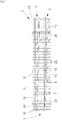
- eine schematische Draufsicht auf eine Weiche 3,
- Fig. 1
- eine schematische Schnittdarstellung eines Weichensegments
mit anliegender Zungenschiene 10 und abliegender Zungenschiene 11, - Fig. 2
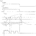
- eine zeitliche Darstellung der Erwärmung einer Weiche 3 mit einer Weichenheizung entsprechend dem Stand der Technik,
- Fig. 3
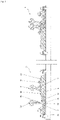
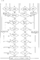
- eine schematische Darstellung eines erfindungsgemäßen Wärmenetzes 26, 27 für ein
Weichensegment der Weiche 3bestehend aus Backenschiene 7,Zungenschiene 8,Gleitstuhlplatte 9 und Heizeinrichtung 14, - Fig. 4
- ein Modell zur Berechnung der Anheizzeit mit und/ ohne Schnee,
- Fig. 5
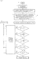
- ein Beispiel für einen Programmablaufplan zur Dimensionierung der Leistung einer Heizeinrichtung 14 in Abhängigkeit projektspezifischer Betriebsgrenzwerte.
- Fig. 6
- ein Beispiel für einen Programmablaufplan zur Bewertung der Funktion der Weichenheizung 1 in Abhängigkeit der Witterung und damit Nachweis der Verfügbarkeit der Weiche 3 im Winter mit vorhandener Leistung der Heizeinrichtung 14 und
- Fig. 7
- ein Beispiel für einen Programmablaufplan (zur besseren Übersicht auf zwei Seiten verteilt) zur Steuerung und Regelung einer erfindungsgemäßen Weichenheizung 1.
- 0
- a schematic plan view of a
switch 3, - 1
- a schematic sectional view of a switch segment with
adjacent tongue rail 10 andremote tongue rail 11, - 2
- a chronological representation of the heating of a
point 3 with a point heater according to the prior art, - 3
- a schematic representation of a
heating network switch 3 consisting ofstock rail 7,tongue rail 8,slide chair plate 9 andheating device 14, - 4
- a model for calculating the heating-up time with and/or without snow,
- figure 5
- an example of a program flow chart for dimensioning the power of a
heating device 14 depending on project-specific operating limits. - 6
- an example of a program flow chart for evaluating the function of the points heating 1 depending on the weather and thus proof of the availability of the
points 3 in winter with the existing power of theheating device 14 and - 7
- an example of a program flow chart (for a better overview on two Distributed on pages) for the control and regulation of points heating according to the
invention 1.
Nachstehend wird die Erfindung im Detail beschrieben, wobei diese Beschreibung anhand konkreter Ausführungsformen den Schutzbereich der Patentansprüche nicht einschränkt.The invention is described in detail below, this description not limiting the scope of protection of the patent claims on the basis of specific embodiments.
Um mit möglichst wenigen Weichentemperatursensoren 28 die vorstehend bereits benannten Ziele zu erreichen, besteht die vorliegende Erfindung unter anderem darin, die Steuerung und Regelung sowie die Dimensionierung der Heizeinrichtungen 14 und die die Ermittlung von Betriebsgrenzen bestehender Weichenheizungen durch Bewertung der Weichentemperaturen der Weiche 3 an den funktionsrelevanten Stellen 19 der Weiche 3 im Winter für die erfindungsgemäße Weichenheizung 1 mittels Berechnung vorzunehmen. Erfindungsgemäß erfolgt das über das Wärmenetz 26 der linken Seite 5 der Weiche 3 und über das Wärmenetz 27 der rechten Seite 6 der Weiche 3 für zumindest ein Weichensegment analog zu elektrischen Strömungsfeldern, indem die Steuerung und Regelung der spezifischen Leistung der Heizeinrichtung 14 der erfindungsgemäßen Weichenheizung 1 durch Bewertung über mittels Wärmenetz 26, 27 berechnete Temperaturen an Weichensegment Weichenspitze 34, Weichensegment Weichenmitte 35 und Weichensegment Weichenende 36 für die linke Seite 5 der Weiche 3 und die rechte Seite 6 der Weiche 3 in Abhängigkeit der Weichenstellung, das heißt für an der Backenschiene anliegende Zungenschiene 10 und für abliegende Zungenschiene 11, und in Abhängigkeit der Witterung erfolgt. Die berechneten optimalen Weichentemperaturen Top der Weiche 3 werden mit den über einen Weichentemperatursensor 28 erfassten zeitlichen Verlauf der realen Weichentemperatur Tw der Weiche 3 aus mindestens drei Messwerten nach Ablauf der Totzeit einer beheizten Schiene mit dem Weichentemperatursensor 28 zumindest einer Weiche 3 verglichen. Bei Differenzen einschließlich einer Toleranz, die bspw. aus Wind und Sonnenstrahlung entstehen können, wird dieser zeitliche Verlauf über Konvektionsverluste und Strahlungsleistung korrigiert.In order to achieve the goals already mentioned above with as few
Die erfindungsgemäße Lösung der vorstehend genannten Aufgaben erfolgt mit einer thermischen Modellierung des Temperaturverlaufs mit Aufteilung der Weiche 3 in Weichensegmente der linken Seite 5 und der rechten Seite 6 für die zur Bewertung der Funktion charakteristischen Bereiche Weichenspitze 16, Weichenmitte 17 und Weichenende 18 unter Berücksichtigung des Abstandes zwischen Backenschiene 7 und Zungenschiene 8 aufgrund der Weichenstellung, des Schienenprofils, der Art der Gleitstuhlplatte 9 mit oder ohne Rollen, der Niederschlagsart und der Niederschlagsmenge, der Windgeschwindigkeit und der Umgebungstemperatur sowie einer möglichen Wärmedämmung bzw. Winddämmung. Dabei werden für die Weichensegmente bei Betrieb mit jeweiliger spezifischen Leistung der Heizeinrichtung 14 der zeitliche Verlauf der Weichentemperaturen Top der Weiche 3 und der spezifischen Leistungsverluste mit iterativen Lösungsverfahren berechnet und mit über Weichentemperatursensoren 28 erfasstem zeitlichen Verlauf der realen Weichentemperaturen Tw der Weiche 3 verglichen. Bei Differenzen werden diese unter Berücksichtigung einer Toleranz korrigiert und an funktionsrelevanten Stellen 19 der Weiche 3, die im Winter für die Funktion der Weiche 3 maßgeblich sind, bewertet, so dass bei Betrieb mit ermittelter witterungsabhängiger optimaler spezifischer Leistung die Heizeinrichtung 14 aktiviert werden und an diesen Stellen eine Schienenmindesttemperatur Tmin der Weiche erreicht wird. Damit wird mit minimalem Energieeinsatz eine gleichmäßige Erwärmung der linken Seite 5 der Weiche 3 und rechten Seite 6 der Weiche 3 über die gesamte Länge der Weiche 3 erreicht und damit eine hohe Verfügbarkeit im Winter gewährleistet.The inventive solution to the above-mentioned tasks is carried out with a thermal modeling of the temperature profile with the division of the
Bei der Dimensionierung wird die erforderliche spezifische Leistung der Heizeinrichtung 14 aufgrund lokaler grenzwertiger Umgebungsbedingungen ermittelt. Bei der Ermittlung von Betriebsgrenzen der erfindungsgemäßen Weichenheizung 1 werden bei vorhandenen Weichenheizungen die Weichenendtemperaturen Twn der Weiche 3 an funktionsrelevanten Stellen 19 bei maximalen Grenzwerten der Umgebungsbedingen ermittelt, bei denen die betreffende Weichenheizung 1 mit vorhandener spezifischer Leistung der Heizeinrichtungen 14 im Betrieb im Winter gerade noch funktioniert. Damit kann der Betreiber entscheiden, ob diese Betriebsgrenze ausreichend oder nichtausreichend für seine Witterungsbedingungen ist.When dimensioning, the required specific power of the
Dafür soll für lokale, projektspezifische und charakteristische ungünstigste Umgebungsbedingungen und alle Typen von Weichen 3 mit entsprechendem jeweiligen Schienenprofil mit einem Programm die erforderliche spezifische Leistung der Heizeinrichtung 14 für beispielsweise einen Meter Länge berechnet werden, die für die Heizeinrichtungen 14 erforderlich sind, damit die erfindungsgemäße Weichenheizung 1 bei diesen Grenzwerten im Winter erfolgreich funktioniert. Das heißt, die Weiche 3 wird schneefrei gehalten wird und friert nicht fest. Zur Bewertung der Funktion werden an den funktionsrelevanten Stellen 19 der Weiche 3 Schienenmindesttemperaturen der Weiche 3 definiert und die Verlustleistungen bei diesen Bedingungen aus Wärmestrahlung 30, Konvektion 3), Wärmeleitung 33 und Wärmespeicher 32 unter Berücksichtigung des Einbauortes der Heizeinrichtung 14 und der Stellung der Zungenschiene 8 an den Weichensegmenten der linken Seite 5 der Weiche 3 und der rechten Seite 6 der Weiche 3 an Weichenspitze 16, Weichenmitte 17 und Weichenende 18 berechnet. Die Summe der Verlustleistungen jedes Weichensegments der linken Seite 5 der Wiche 3 und/oder der rechten Seite 6 der Weiche 3, bei der die Schienenmindesttemperaturen der Weiche 3 erreicht und die Schneemenge geschmolzen wird, entspricht der erforderlichen spezifischen Heizleistung für die jeweilige Seite und den jeweilige Bereich der Weiche 3. Die Heizeinrichtungen weisen eine Länge von bis zu 6 m auf. Deshalb wird vorteilhaft die erforderliche spezifische Heizleistung der Heizeinrichtungen 14 aus der berechneten maximalen Summe der Verlustleistung der Weichensegmente der linken Seite 5 der Weiche 3 und der rechten Seite 6 der Weiche 3 ermittelt.For local, project-specific and characteristic unfavorable environmental conditions and all types of
Diese Ermittlung erfolgt derart, dass u.a. für ein bestimmtes Schienenprofil, z.B. R54, minimale Umgebungstemperaturen und maximale Schneemenge vorgegeben werden und für funktionsrelevante Stellen 19 von Weichensegmenten an Weichenspitze 34, Weichenmitte 35 und Weichenende 36 der zeitliche Verlauf und die Verlustleistungen der Wärmleitung 33, der Schmelzleistungen und der Verdampfungsleistung Pv die optimalen Weichentemperaturen (Top) berechnet und bewertet sowie erkannt werden, ob die gesamte Schneemenge geschmolzen wird. Es werden folgende projektspezifische Eingaben eingegeben, die die Betriebsgrenze der erfindungsgemäßen Weichenheizung 1 darstellen, d.h. bei denen die Funktion der Weichen 3 im Winter noch gewährleistet sein soll:
- Weichenprofil, z.B. R54 mit unterschiedlichen Abmessungen und Gewicht an
Weichenspitze 16,Weichenmitte 17 und Weichenende 18, - Schienensolltemperatur TSoll der
Weiche 3, - Schienenmindesttemperatur Tmin der
Weiche 3 und/oder minimale Umgebungstemperatur Tu-min, - maximale Schneemenge hS-max,
- maximale Anheizzeit beheizte Schiene tAn-max,
- maximale Windgeschwindigkeit umax.
- Switch profile, e.g. R54 with different dimensions and weight at
switch tip 16, switch middle 17 and switchend 18, - Set rail temperature T set point 3,
- Minimum rail temperature T min of
points 3 and/or minimum ambient temperature Tu-min, - maximum amount of snow h S-max ,
- maximum heating time heated rail t An-max ,
- maximum wind speed u max .
Das Berechnen der Endwerte der Verlustleistungen für das Weichensegment rechte Seite 6 der Weiche 3 und das Weichensegment linke Seite 5 der Weiche 3 erfolgt bei einer Weichenendtemperatur der Weiche 3, die zumindest der absoluten Summe aus Schienenmindesttemperatur Tmin der Weiche 3 oder der Umgebungstemperatur Tu und der unteren Weichensolltemperatur (bspw. 7 °C abzüglich 4 °C Hysterese ergibt 3 °C) der Schienenmindesttemperatur der weiche 3 der beheizten Schienen, bspw. Backenschienen 7 links und rechts (z.B. Knoten K Backenschienenfuß) und/oder der parametrierten Mindesttemperatur an den funktionsrelevanten Stellen 19, z.B. + 1 °C entspricht, wobei die Summe der Verlustleistungen der erforderlichen spezifischen Leistung der Heizeinrichtung 14 in Watt pro Meter für eine Länge der Heizeinrichtung 14 entspricht.The calculation of the final values of the power losses for the switch segment
Aus maximaler Schneemenge hs, den waagerechten Flächen des Weichensegments und der mittleren Dichte von Schnee, z.B. von 100 kg/m3, bei Lufttemperatur kleiner 0 °C und 200 kg/m3 bei Lufttemperatur größer 0 °C und einer mittleren spezifischen Schmelzwärme von bspw. 335 kJ/Kg wird die erforderliche Schmelzleistung für die Schneemenge in einer Stunde ermittelt. Schnee beginnt bei 0 °C zu schmelzen. Die gesamte erforderliche spezifische Leistung der Heizeinrichtungen 14 ergibt sich aus der Summe der Verlustleistungen bei bspw. 0 °C und der Schmelzleistung der Schneemenge, die zwischen Heizbeginn und Erreichen der Schienenmindesttemperatur Tmin der Weiche 3 von bspw. 0 °C am Fuß-Backenschiene gefallen ist. Die gefallene Schneemenge ermittelt sich aus erfasster Schneemenge und der Zeit bis zum Erreichen der Schienenmindesttemperatur Tmin der Weiche 3, die der Schmelztemperatur von Schnee entspricht.From the maximum amount of snow hs, the horizontal surfaces of the switch segment and the mean density of snow, e.g. 100 kg/m 3 at an air temperature below 0 °C and 200 kg/m 3 at an air temperature above 0 °C and a mean specific heat of fusion of e.g 335 kJ/Kg is the required melting capacity for the amount of snow in one hour. Snow starts to melt at 0°C. The total required specific power of the
Eine erfolgreiche Funktion der erfindungsgemäßen Weichenheizung 1 im Winter soll an den funktionsrelevanten Stellen 19 der Weiche 3 eine Schienenmindesttemperatur Tmin der Weiche 3 an linker Seite 5 der Weiche 3 und rechter Seite 6 der Weiche 3 gewährleisten, wobei die Schienenmindesttemperatur Tmin der Weiche 3 der Schmelztemperatur von Eis und Schnee entspricht. Diese funktionsrelevanten Stellen sind:
Dabei berücksichtigt der Faktor k Temperaturdifferenzen aufgrund von Wärmeleitungen zwischen den Stellen ![]()
![]()
![]()
![]()
![]()
![]()
![]()
![]()
![]()
![]()
![]()
![]()
Damit für alle Weichentypen nur ein Programm erforderlich ist, erfolgt die Bewertung an typischen Weichensegmenten für die linke Seite 5 der Weiche 3 und die rechte Seite 6 der Weiche 3 über die Bereiche Weichenspitze 35, Weichenmitte 36 und Weichenende 37. Bewertet werden parametrierbare Werte für die linke Seite 5 der Weiche 3 und die rechte Seite 6 der Weiche 3 eines Weichensegments, bspw: ![]()
![]()
![]()
![]()
![]()
![]()
![]()
![]()
![]()
![]()
![]()
![]()
Anheizzeit tA <= t A-max geschmolzene Schneemenge während der Anheizzeit t Am größer gefallene Schneemenge hs durch Bewerten der vorhandenen spezifischen Leistung der Heizeinrichtung 14 mit der erforderlichen Erhaltungsleistung Perh zuzüglich Schmelzleistung für die gefallenen Schneemenge.Heating time t A <= t A-max Amount of snow melted during the heating time t Am Larger amount of snow h s that has fallen by evaluating the existing specific power of the
Mit dem Berechnungsverfahren in Verbindung mit einer Steuereinrichtung zu Steuerung und Regelung können folgende Maßnahmen zur Gewährleistung der Funktion der Weiche 3 bei minimalem Energieverbrauch über den gesamten Betriebsbereich aktiviert werden.With the calculation method in connection with a control device for control and regulation, the following measures to ensure the function of the
Anordnung von zusätzlichen Heizeinrichtungen 29 an der Zungenschiene 8 und/oder den Gleitstuhlplatten 9, die über das Berechnungsmodell zeitlich oder über Leistungsaufteilung so aktiviert und gesteuert werden, dass ohne Erhöhung der Anschlussleistung die funktionsrelevanten Stellen 19 zeitlich gleichmäßig erwärmt werden und damit keine zeitlichen Nachteile einzelner Teile der Weiche 3 eintreten.Arrangement of
Bei mittels Berechnungsverfahren prognostizierten Defiziten der Weichentemperaturen der Weiche 3 aufgrund unzureichend vorhandener spezifischer Leistung der Heizeinrichtung 14 an der abliegender Zungenschiene 11 erfolgt frühzeitige Warnmeldung oder Meldung möglichst Weiche 3 umstellen und/oder Vorheizen auf eine geringe Schienensolltemperatur der Weiche 3, so dass bei Wetterextremen durch bspw. starken Schneefall der Schnee sofort schmilzt.In the event of deficits in the point temperatures of
Zur erfolgreichen Funktion der erfindungsgemäßen Weichenheizung 1 ist eine gleichmäßige Erwärmung der funktionsrelevanten Stellen 19 der Weiche 3 der anliegenden und abliegenden Zungenschiene 8 erforderlich. Da die Weiche 3 im Betrieb laufend in Abhängigkeit der Fahrtrichtung umgestellt wird und für die Weichenstellung keine Sensoren zur Detektion der Lage der Zungenschiene 8 möglich sind, wird vorschlagen, durch Auswertung des berechneten zeitlichen Verlauf der Weichentemperatur der Weiche 3 an der linken Seite 5 der Weiche 3 und an der rechten Seite 6 der Weiche 3 die Lage der Zungenschienen 8 zu detektierenFor the successful functioning of the points heating 1 according to the invention, a uniform heating of the functionally
Heizeinrichtung-Bestückungsvarianten sind:
Heizeinrichtung 14 an den Backenschienen 7 und zusätzliche Heizeinrichtung 29 an den Zungenschienen 8 und bei Beginn des Betriebes Anheizen von ersten Schienen mit 100 % spezifischer Leistung der Heizeinrichtung 14, wobei erste Schienen Backenschienen 7 oder Zungenschiene 8 oder Gleitstuhlplatten 9 sein können, und bei Erreichen der Schienensolltemperatur TSoll der Weiche 3 an der ersten Schiene Reduzieren der jeweiligen spezifischen Leistung der Heizeinrichtung 14 oder 29 auf maximal spezifische Erhaltungsleistung PErh oder geringer oder Ausschalten derselben und Aktivieren der zusätzlichen Heizeinrichtung 29 an der Zungenschiene 7 oder den Gleitstuhlplatten 9 mit der verbleibenden spezifischen Leistung ab dieser Zeit und nur in den Heizpausen der Heizeinrichtung 14 der ersten Schienen bspw. über Gruppenbetrieb während zyklischer Taktzeiten bei elektrischen Heizstäben.Heating device assembly variants are:
Bei berechneten Defiziten vor einer Heizanforderung bspw. durch Schnee an der Wetterstation erfolgt Aktivieren von zusätzlichem Heizregime "Vorheizen", bspw. bei möglichen Wetterextremen über separate Wetterdaten aus einer örtlichen Wetterstation bzw. über einen Wetterdienst derart, dass ein zweite Schienensolltemperatur der Weiche 3 berechnet wird und die erfindungsgemäße Weichenheizung 1 über Vorheizen in Betrieb geschaltet wird und auf diese zweite Schienensolltemperatur der Weiche 3 geregelt wird, wobei die zweite Schienensolltemperatur der Weiche 3 so groß ist, dass bei Eintreten der tatsächlichen Wetterextreme der Schnee geschmolzen und die Funktion der Weiche 3 gewährleistet und bei Ausbleiben der Wetterextreme das Vorheizen beendet wird.If deficits are calculated before a heating requirement, e.g. due to snow at the weather station, additional heating regime "preheating" is activated,
Bei Bestückung der Backenschiene 7 und der Zungenschiene 8 und/oder der Gleitstuhlplatten 9 mit zusätzliche Heizelementen 29 erfolgt bei Betrieb während der Anheizzeit die Aktivierung der Heizeinrichtungen 14 immer nacheinander, d.h. zuerst Aktivieren der Heizeinrichtung 14 der ersten Schiene mit einem Leistungsverhältnis 100 % und nach Erreichen der Schienensolltemperatur der Weiche 3 Aktivieren der Heizeinrichtung 29 der zweiten Schiene in den Heizpausen der Heizeinrichtung 14 der ersten Schiene und im Regelbetrieb, d.h. wenn beide Schienen Schienensolltemperatur der Weiche 3 aufweisen, erfolgt Gruppenbetrieb oder Wellenpaketsteuerung oder gleichzeitiger Heizbetrieb aller Heizeinrichtungen 14, 29 mit verringerter spezifischer Leistung oder aktiver Heizzeit, wobei die Summe der spezifischen Leistung der Heizeinrichtungen 14, 29 der linken Seite 5 der Weiche 3 und der rechten Seite 6 der Weiche 3 maximal der spezifischen Leistung der Heizeinrichtung 14 entsprechen.When equipping the
Korrektur des berechneten zeitlichen Verlaufs der Schienensolltemperatur der Weiche 3 mit dem tatsächlich erfassten zeitlichen Verlauf der Weichentemperatur der Weiche 3 mittels Weichentemperatursensor 28 unter Berücksichtigung von Strahlungswärme durch Sonnenstrahlung und Windeinfluss über Konvektion.Correction of the calculated course over time of the target rail temperature of the
Nachfolgend wird eine detaillierte Beschreibung der Figuren gegeben.A detailed description of the figures is given below.
In
In
In
Zum Zeitpunkt t6 wird durch die parametrierte Hysterese von bspw. 4 °C der Heizstrom für alle Heizeinrichtungen der Weiche ausgeschaltet, so dass auch an der Gleitstuhlplatte die Kühlung einsetzt. Die Weichentemperaturdifferenz ΔTW zur Zeit t6 zwischen Fuß Backenschienen und Gleitstuhlplatt ist sehr groß. Diese Weichentemperaturdifferenz ΔTW ist bei einer Umgebungstemperatur von bspw. - 15 °C so groß, dass an der Gleitstuhlplatte außen die Weichentemperatur auch nach sehr langer Zeit kleiner 0 °C beträgt und die Weiche an dieser Stelle Eis ansetzt und festfrieren kann. In
In
Im Wärmenetz 26 der linken Seite 5 der Weiche 3 ist zwischen der Umgebungstemperatur Tu, die durch Knoten K Umgebungstemperatur KTU repräsentiert wird, und funktionsrelevanten Stellen 19, die ebenfalls durch Knoten K repräsentiert werden, ein Wärmenetz vorhanden, das mit bekannten Regeln berechnet werden wird. Die Knoten K für die funktionsrelevanten Stellen 19 der Weiche 3 für das Wärmenetz 26 für die linke Seite 5 der Weiche 3 und für das Wärmenetz 27 für die rechte Seite 6 der Weiche 3 sind gleich und entsprechend der Bewertungspunkte 37 bis 43, aber die Verlustleistungen der anliegende Zungenschiene 10 und abliegende Zungenschiene 11 sind unterschiedlich. Die folgende Tabelle zeigt den Zusammenhang zwischen den funktionsrelevanten Stellen 19, den entsprechenden Knoten K und der erforderlichen Weichentemperatur TW, die an den jeweiligen Knoten K mit der Bezeichnung T W-op berechnet wird und in einem separaten Programm bewertet wird für das Wärmenetz 26 für die linke Seite 5 der Weiche 3. Das Wärmenetz 27 für die rechte Seite 6 der Weiche 3ist analog dazu und über den Knoten K Umgebungstemperatur KTU verbunden.
Zur Berechnung der Weichentemperaturen der Weiche 3 und der Verlustleistungen wird das Weichensegment in Abschnitte zerlegt und jeder Abschnitt wird durch einen Knoten K repräsentiert, der die mittlere Weichentemperatur Tw des zugeordneten Abschnittes angibt. Die Größe der Abschnitte bzw. die Anzahl der Knoten K hängen von der geforderten Nachbildungsgenauigkeit ab. Für alle Knoten K werden die Verlustleistungen und Wärmewiderstände und Wärmekapazitäten aus den Stoffeigenschaften, den geometrischen Größen und den vorherrschenden Belastungen durch Heizstrom IN und Umwelt berechnet. Aus der Verbindung der Knoten K durch Widerstände, Kondensatoren und Spannungsquellen entsteht ein Netzwerk, das mit Hilfe des Knoten- und Maschensatzes numerisch gelöst werden kann. Wird die Leistungsbilanz für einen Knoten K erstellt, gilt der Kirchhoffsche Satz (Knotensatz). ![]()
![]()
Nach dem 2. Kirchhoffschen Satz (Maschensatz) folgt, dass entlang einer geschlossenen Linie, d. h. einer Masche, die Summe der vorzeichenbehafteten Temperaturdifferenzen gleich Null ist. Mit einem Softwareprogramm erfolgt die Berechnung der Verlustleistungen und der Wärmetransportvorgänge. Die temperaturabhängigen Wärmeleistungen und Wärmewiderstände werden entsprechend den bekannten Berechnungsgrundlagen berechnet und an den funktionsrelevanten Stellen 19 der Weiche 3, die im Wärmenetz 26, 27 durch Knoten K repräsentiert werden, und unter Einbeziehung der Wärmekapazitäten die Endtemperatur und der zeitliche Verlauf der Weichentemperaturen berechnet.According to Kirchhoff 's second theorem (mesh theorem), it follows that along a closed line, ie a mesh, the sum of the signed temperature difference is zero. The power loss and heat transport processes are calculated using a software program. The temperature-dependent thermal outputs and thermal resistances are calculated according to the known calculation bases and at the functionally
In
Die Berechnung der Anheizzeit tA erfolgt für zumindest ein Weichensegmente für die linke Seite 5 der Weiche 3 und die rechte Seite 6 der Weiche 3 in mehreren Schritten unter Berücksichtigung von Zeiten, in denen die Erwärmung des Weichensegments bis zur Weichenmindesttemperatur TW-min der Weiche 3, Schnee schmelzen, Verdampfen von Wasser und danach bis zur Weichensolltemperatur TSoll der Weiche 3 erfolgt. In
Die Anheizzeit tA ist die Zeit bis zum Erreichen der Schmelztemperatur von Schnee bis zur Zeit t 2.1. Ab der Zeit t2 wird die Weiche 3 bis zur Schmelztemperatur Ts erwärmt, die zur Zeit t 2.1 erreicht wird. Die Berechnung der Anheizzeit tA erfolgt über mit dem Wärmenetzmodell ermittelten Wärmewiderstand Rth und Wärmekapazität Cth und der Verlustleistung der Weiche 3 auf Grundlage des zeitlichen Verlaufs beginnend ab Weichentemperatur kalte Schiene TK der Weiche 3 bis zum Erreichender Schmelztemperatur Ts bspw. über die Formeln ![]()

![]()
Die Zeit zum Schmelzen der gefallenen oder projektspezifisch erforderlichen Schneemenge besteht aus zwei Teilzeiten tA2 und tA3. Während der Zeit tA2 wird die Zeit zum Schmelzen der Schneemenge aus der Zeit tA1 berechnet und während der Zeit tA3 wird die während der Zeit tA2 gefallene Schneemenge berechnet. Die Berechnung der Schmelzleistung pro Stunde erfolgt aus Schneemenge hs und den waagerechten Flächen des Weichensegments und einer mittleren Dichte von Schnee, z.B. von 100 kg/m3 bei Lufttemperatur kleiner 0 °C und 200 kg/m3 bei Lufttemperatur größer 0 °C und einer mittleren spezifischen Schmelzwärme von bspw. 335 kJ/Kg. Schnee beginnt bei 0 °C zu schmelzen. Die Berechnung der spezifischen Leistung erfolgt deshalb bspw. bei einer Weichentemperatur von 0 °C an der Backenschiene 7 unter Berücksichtigung der erforderlichen optimalen spezifischen Leistung der Heizeinrichtung 14 zur Erhaltung der Schmelztemperatur der Backenschiene 7, die der Summe der Verlustleistungen bei dieser Schmelztemperatur entspricht.The time taken to melt the amount of snow that has fallen or is required for the specific project consists of two partial times t A2 and t A3 . During time t A2 the time for melting the amount of snow is calculated from time t A1 and during time t A3 the amount of snow fallen during time t A2 is calculated. The calculation of the melting capacity per hour is based on the amount of snow hs and the horizontal surfaces of the switch segment and an average density of snow , e.g average specific heat of fusion of e.g. 335 kJ/Kg. Snow starts to melt at 0°C. The specific power is therefore calculated, for example, at a point temperature of 0 °C on the
Die Berechnung der gesamten Anheizzeit tA2 plus tANH3 zum Schmelzen des gesamten Schneemenge aus der Anheizzeit tA1 und der Anheizzeit tA2 erfolgt aus dem Produkt aus Schmelzleistung pro Stunde und der Summe aus Zeit tANH1 und Zeit tANH2 und Totzeit tT.The total heating-up time t A2 plus t ANH3 for melting the entire amount of snow from the heating-up time t A1 and the heating-up time t A2 is calculated from the product of the melting capacity per hour and the sum of time t ANH1 and time t ANH2 and dead time t T .
Nachdem der Schnee geschmolzen ist, wird die Weiche 3 weiter erwärmt. Die Anheizzeit tA4 beginnt zur Zeit t 2.3 und endet mit Erreichen der Schienensolltemperatur TSoll der Weiche 3 durch den Weichentemperatursensor 28. Die Berechnung der Anheizzeit tA4 erfolgt über das mit Wärmenetzmodell ermittelten Wärmewiderstand Rth und Wärmekapazität Cth und der Verlustleistung auf Grundlage des zeitlichen Verlaufs beginnend ab Schmelztemperatur bis zum Erreichen der Weichensolltemperatur analog Pkt. 1 mit entsprechend absoluter Weichentemperatur aus der Differenz Weichensolltemperatur und Schmelztemperatur.After the snow has melted, the
Während der Anheizzeit tA5 wird der Schnee aus der Anheizzeit tA4 geschmolzen. Die Berechnung erfolgt analog der Anheizzeit tA2 bzw. tA3.During the heating-up time t A5 the snow from the heating-up time t A4 is melted. The calculation is analogous to the heating-up time t A2 or t A3 .
Die gesamte Anheizzeit tA dauert von Zeit t1 bis t7 und wird aus der Summe aus Totzeit und Anheizzeiten tA1 bis tA5 ermittelt und bewertet.The entire heating-up time t A lasts from time t 1 to t 7 and is determined and evaluated from the sum of dead time and heating-up times t A1 to t A5 .
In
- 4. Schritt: Berechnen der Weichentemperaturen und spezifischen Verlustleistungen ΣPV1 für 1. Weichensegment mittels Wärmenetzmodell aus den Stoffeigenschaften, den geometrischen Größen und den eingegebenen Parametern und Ausgabe der Summe Verlustleistung des Weichensegments und der Weichentemperaturen für die
funktionsrelevanten Stellen 19 anliegende und abliegende Seite des Weichensegments - 5. Schritt: Berechnen spezifische Verlustleistungen ΣPVn für weitere Weichensegmente
analog 4. Schritt - 6. Schritt: Die erforderliche spezifische Heizleistung Perf ergibt sich aus der Summe der Verlustleistungen ΣPVn jedes Weichensegments.
- 7. Schritt: Prüfen, wird mit der berechneten spezifischen Leistung an dem Standort des Weichentemperatursensors, anliegende oder abliegende Seite, die Weichensolltemperatur erreicht? Bei "Ja" weiter zu Schritt 10., bei "Nein" weiter zu
Schritt 8. - 8. Schritt: Bewertung
Die berechnete Weichenendtemperatur der Weiche 3 am Fuß Backenschiene anliegende Seite TW-Fu-Ba-an oder abliegende Seite TW-Fu-Ba-ab ist kleiner als die Weichensolltemperatur TSoll derWeiche 3, Ergebnis istWeichenendtemperatur der Weiche 3 an Backenschienenfuß (T W-Fu-Ba) ist zu gering, die Weichensolltemperatur TSoll derWeiche 3 wird nicht erreicht, weitermit Schritt 9. - 9. Schritt: Erhöhen der spezifischen Leistung P der Heizeinrichtung 14 um einen Leistungszuschlag p von bspw. 10 Watt pro Meter und Wiederholung der Berechnung nach
Schritt 4. - 10. Schritt: Prüfen, ist die berechnete Weichenendtemperatur der Weiche 3 am Kopf Backenschiene anliegende Seite TW-Ko-Ba-an oder abliegende Seite TW-Ko-Ba-ab kleiner als die Weichenmindesttemperatur TW-Min der
Weiche 3? Ist bspw. die berechnete Weichentemperatur der Weiche 3 an Kopf-Backenschiene T op-Ko-Ba der anliegenden oder abliegende Seite kleiner als die parametrierte Weichenmindesttemperatur TW-Min,weiter mit Schritt 9. Ist die berechnete Weichentemperatur der Weiche 3 an Kopf-Backenschiene anliegende und abliegende Seite (T op-Ko-Ba-an, T op-Ko-Ba-ab ) größer oder gleich der Schienenmindesttemperatur derWeiche 3, weiter zuSchritt 11. - 11. Schritt: Prüfen, ist die berechnete Weichenendtemperatur der Weiche 3 am Kopf-Zungenschiene 21 anliegende Seite Top-Ko-Zu-an oder abliegende Seite TW-Ko-Zu-ab kleiner als die Weichenmindesttemperatur TW-Min der
Weiche 3? Bei "JA" weiter zu Schritt 9., bei "Nein" weiter zuSchritt 12. - 12. Schritt: Prüfen, ist die berechnete Weichenendtemperatur der Weiche 3 an Außen-Gleitstuhlplatte anliegende Seite TW-GL-au -an oder abliegende Seite TW-GL-au-ab kleiner als die Weichenmindesttemperatur TW-Min der
Weiche 3? Bei "JA" weiter zu Schritt 9., bei "Nein" weiter zuSchritt 13. - 13. Schritt: Schneemenge wird geschmolzen
Prüfen, wird die maximale Schneemenge geschmolzen oder nicht über Vergleich der Summe aus berechneter spezifischer Erhaltungsleistung PErh bei Weichenmindesttemperatur TW-Min derWeiche 3 und spezifischer Schmelzleistung Psm für die maximale Schneemenge hS mit der berechneten spezifischen Leistung (Pop)? Ist die berechnete spezifische Leistung Pop größer oder gleich der Summe aus Erhaltungsleistung PErh und Schmelzleistung PSm, weiter zu Schritt 14., sonst weiter zuSchritt 9. - 14. Schritt: Ausgabe der erforderlichen spezifischen Leistung Heizeinrichtung P für eine Weichenheizung 1, die im automatischen Betrieb bis zu den Eingabeparametern die Verfügbarkeit der Weiche im Winter bei geringen Energieverbrauch gewährleistet.
- 4th step: Calculation of the switch temperatures and specific power losses ΣP V1 for the 1st switch segment using a heat network model from the material properties, the geometric variables and the entered parameters and output of the total power loss of the switch segment and the switch temperatures for the functionally
relevant points 19 adjacent and remote side of the switch segment - 5th step: Calculate specific power losses ΣP Vn for further switch segments analogous to 4th step
- 6th step: The required specific heating power Perf results from the sum of the power losses ΣP Vn of each switch segment.
- 7th step: Check, is the set point temperature reached with the calculated specific power at the location of the point temperature sensor, adjacent or remote side? If "yes" continue to step 10., if "no" continue to step 8.
- 8th step: evaluation
The calculated point end temperature ofpoint 3 at the foot of the stock rail lying side T W-Fu-Ba-an or the opposite side T W-Fu-Ba-down is lower than the set point temperature T set point 3, the result is the point end temperature ofpoint 3 at the stock rail foot ( T W-Fu-Ba ) is too low, the set point temperature T set point 3 is not reached, continue withstep 9. - 9th step: Increase the specific power P of the
heating device 14 by a power supplement p of e.g. 10 watts per meter and repeat the calculation according tostep 4. - 10th step: Check, is the calculated final point temperature of
point 3 on the side T W-Ko-Ba-on or the side T W-Ko-Ba-down lying on the head of the stock rail less than the minimum point temperature T W-Min ofpoint 3? If, for example, the calculated switch temperature ofswitch 3 on the head stock rail T op-Ko-Ba on the adjacent or remote side is lower than the configured minimum switch temperature T W-Min , continue withstep 9. Is the calculated switch temperature ofswitch 3 on the head stock rail adjacent and opposite sides (T op-Ko-Ba-an , T op-Ko-Ba-ab ) greater than or equal to minimum rail temperature ofswitch 3, go to step 11. - 11th step: Check whether the calculated point end temperature of
point 3 on the head tongue rail 21 adjacent side T op-Ko-Zu-an or remote side T W-Ko-Zu-ab is smaller than the minimum point temperature T W-Min ofpoint 3 ? If "YES" continue to step 9., if "No" continue to step 12. - 12th step: Check, is the calculated end point temperature of
switch 3 on the side T W-GL-au -on or on the opposite side T W-GL-au-ab lower than the minimum point temperature T W-Min ofswitch 3? If "YES" continue to step 9., if "No" continue to step 13. - 13th step: amount of snow is melted
Check whether the maximum amount of snow is melted or not by comparing the sum of the calculated specific maintenance power P Erh at the minimum switch temperature T W-Min ofswitch 3 and the specific melting power Psm for the maximum amount of snow h S with the calculated specific power (P op )? If the calculated specific power P op is greater than or equal to the sum of maintenance power P Erh and melting power P Sm , go to step 14, otherwise go tostep 9. - 14th step: Output of the required specific output of heating device P for
points heating 1, which, in automatic operation up to the input parameters, ensures the availability of the points in winter with low energy consumption.
In
Nachfolgend werden die Schritte für die Bewertung einer vorhandenen Weichenheizung 1 bei minimaler Umgebungstemperatur Tu-min, maximaler Schneemenge pro Stunde hS und max. Windgeschwindigkeit vmax dargestellt.
- Schritt1: Start des Programmes
- Schritt 2: Eingabe von minimal zu erwartender Umgebungstemperatur Tumin, spezifischen Leistungen Heizeinrichtung P, Weichensolltemperatur TSoll, maximaler Windgeschwindigkeit Vmax, Schienenprofil R der
Weiche 3, maximaler Schneemenge pro Stunde hs und Standort der Heizeinrichtungen 14 anBackenschiene 7 und/oder Zungenschiene 8 und/oder Gleitstuhlplatte 9, Weichenmindesttemperatur Tmin. - Schritt 3: Die optimale spezifische Leistung Heizeinrichtung anliegende (linke) Seite P op-Li und die optimale spezifische Leistung Heizeinrichtung abliegende (rechte) Seite P op-Re ergibt sich aus der spezifischen Leistung Heizeinrichtung P an
den jeweiligen Backenschienen 7,Zungenschienen 8 bzw.Gleitstuhlplatten 9. - Schritt 4: Für anliegende (linke)
Seite 5der Weiche 3 und abliegende (rechte)Seite 6der Weiche 3 wird je ein Weichensegment mit je einem Wärmenetzmodell gebildet, wobei für die anliegende (linke)Seite 5der Weiche 3die Zungenschiene 8 bspw. anliegend und für die abliegende (rechte)Seite 6der Weiche 3die Zungenschiene 8 abliegend dargestellt ist, und es erfolgt über Berechnung der Verlustleistungen Strahlung Pst, Konvektion PK, Wärmeleitung PL, Schmelzwärme PSm und Wärmespeicherung Pc bei spezifischer Leistung Heizeinrichtung P die Berechnung der Weichentemperatur T derWeiche 3 zur Zeit t6 der Anheizzeit tA bei Erreichen der Weichensolltemperatur TSoll derWeiche 3 und über Berechnung der Erhaltungsleistung zum Zeit t2.1 der Anheizzeit tA bei Erreichen der Weichenmindesttemperatur Tmin derWeiche 3. - Schritt 5: Ausgabe der Weichentemperaturen T und der Summe der Verlustleistungen anliegenden (linken) Seite ΣPV-Li und der Summe der Verlustleistungen abliegende (rechte) Seite ΣPV-Re
- Schritt 6: Prüfen, ist die berechnete optimale Weichentemperatur
T der Weiche 3am Weichentemperatursensor 28, bspw. an Fuß-Backenschiene anliegende (linke) Seite, anliegend, und abliegende (rechte)Seite 6, größer als die Weichensolltemperatur TSoll derWeiche 3 unter Berücksichtigung eines Faktors k, bspw.von - Schritt 7: Prüfen, ist die berechnete optimale Weichentemperatur
T der Weiche 3 am Kopf-Zungenschiene anliegend (linke Seite 5) und abliegend (rechte Seite 6) größer oder gleich der Weichenmindesttemperatur der Weiche 3? Wenn "JA" weiter zu Schritt 8., wenn "NEIN" weiter zu Schritt 13.. - Schritt 8: Prüfen, ist die berechnete optimale Weichentemperatur
T der Weiche 3 an Außen-Gleitstuhlplatte anliegend (linke Seite 5) und abliegend (rechte Seite 6) größer oder gleich der Weichenmindesttemperatur der Weiche 3? Wenn "JA" weiter zu Schritt 14., wenn "NEIN" weiter zu Schritt 13.. - Schritt 9: Ermitteln der erforderlichen spezifischen Leistung aus der Summe von Erhaltungsleistung zur Erhaltung der Weichenmindesttemperatur der Weiche 3 an
Backenschiene 7 und Schmelzleistung anliegende (linke) Seite PSm-Li und Schmelzleistung abliegende (rechte) Seite PSm-Li zum Schmelzen der bisher gesamten Schneemenge, die sich aus erfasster Schneemenge pro Zeiteinheit und der Zeit t2.3 der Anheizzeit tA ergibt. - Schritt 10: Prüfen, ist die erforderliche spezifische Leistung der anliegenden (linken) Seite P erf-Li oder die erforderliche spezifische Leistung der abliegenden (rechten) Seite P erf-Re kleiner gleich der spezifischen Leistung Heizeinrichtung P? Wenn "JA" weiter zu Schritt 11., wenn "NEIN" weiter zu Schritt 12..
- Schritt 11: Die gefallene Schneemenge ist kleiner oder gleich der geschmolzenen Schneemenge. Der gefallene Schnee wird während der Anheizzeit geschmolzen. Schritt 12: Die gefallene Schneemenge ist größer der geschmolzenen Schneemenge. Der gefallene Schnee wird während der Anheizzeit nicht geschmolzen. Schritt 13: Ausgabe Defizit für anliegende und abliegende Seite mit hier nicht näher angeführtem Text.
- Schritt 14: Ausgabe der Betriebsgrenzwerte mit bspw. Minimalwerten aus Weichentemperaturen der Weiche 3 anliegende (linke) Seiten 5 und abliegende (rechte)
Seiten 6 Kopf-Backenschienen, Kopf-Zungenschienen sowie geschmolzene Schneemenge.
- Step 1: Start the program
- Step 2: Enter the minimum expected ambient temperature Tumin, specific output of the heating device P, set point temperature T set , maximum wind speed V max , rail profile R of the
points 3, maximum amount of snow per hour hs and location of theheating devices 14 on thestock rail 7 and/ortongue rail 8 and /or slidechair plate 9, switch minimum temperature T min . - Step 3: The optimum specific output of the heating device on the (left) side P op-Li and the optimum specific output of the heating device on the opposite (right) side P op-Re result from the specific output of the heating device P on the
respective stock rails 7, tongue rails 8 or slidechair plates 9. - Step 4: For adjacent (left)
side 5 ofswitch 3 and remote (right)side 6 ofswitch 3, a switch segment is formed, each with a heat network model, whereby for the adjacent (left)side 5 ofswitch 3,switch rail 8, for example adjacent and for the remote (right)side 6 of theswitch 3 theswitch rail 8 is shown remote, and the power losses of radiation Pst, convection P K , heat conduction P L , heat of fusion P Sm and heat storage Pc are calculated for the specific power of the heating device P die Calculation of the point temperature T ofpoint 3 at time t6 of the heating time t A when the point setpoint temperature T set ofpoint 3 is reached and via calculation of the maintenance power at time t2.1 of the heating time t A when the point minimum temperature T min ofpoint 3 is reached. - Step 5: Output of the switch temperatures T and the sum of the power losses on the adjacent (left) side ΣP V-Li and the sum of the power losses on the opposite (right) side ΣP V-Re
- Step 6: Check if the calculated optimum point temperature T of
point 3 at thepoint temperature sensor 28, e.g. the (left) side adjacent to the base stock rail, adjacent, and remote (right)side 6, is greater than the set point temperature T set point 3 below Consideration of a factor k, e.g. 1.5? If "YES" continue to step 7., if "NO" continue to step 13.. - Step 7: Check, is the calculated optimum point temperature T of
point 3 adjacent to the head tongue rail (left side 5) and aside (right side 6) greater than or equal to the minimum point temperature ofpoint 3? If "YES" continue to step 8., if "NO" continue to step 13.. - Step 8: Check, is the calculated optimal switch temperature T of
switch 3 adjacent to the outer slide chair plate (left side 5) and off (right side 6) greater than or equal to the minimum switch temperature ofswitch 3? If "YES" go to step 14., if "NO" go to step 13.. - Step 9: Determining the required specific power from the sum of maintenance power to maintain the
minimum point 3 temperature onstock rail 7 and melting power on the (left) side P Sm-Li and melting power on the remote (right) side P Sm-Li for melting the total Amount of snow resulting from the amount of snow recorded per unit of time and the time t2.3 of the heating-up time t A . - Step 10: Check, is the required specific power of the adjacent (left) side Perf-Li or the required specific power of the remote (right) side Perf -Re less than or equal to the specific power of the heating device P? If "YES" continue to step 11., if "NO" continue to step 12..
- Step 11: The amount of snow that has fallen is less than or equal to the amount of snow that has melted. The fallen snow is melted during the heating up period. Step 12: The amount of snow that has fallen is greater than the amount of snow that has melted. The fallen snow is not melted during the heating up period. Step 13: Issue deficit for attached and attached page with text not detailed here.
- Step 14: Output of the operating limit values with, for example, minimum values from switch temperatures of the
switch 3 adjacent (left) sides 5 and remote (right) sides 6 head stock rails, head tongue rails and the amount of melted snow.
Das gleiche Programm kann in die Steuerung und Regelung integriert werden, indem anstelle von Minimalwerten bzw. Maximalwerten die aktuelle Umgebungstemperatur, Windgeschwindigkeit und Schneemenge eingelesen werden und geeignete Korrekturmaßnahmen oder Warnmeldungen aktiviert werden. Eine geeignete Korrektur ist bspw. zusätzliche Heizeinrichtungen an den Gleitstuhlplatten 9 oder Zungenschienen 8 anzuordnen und die Heizeinrichtungen an diesen zuerst zu aktivieren, so dass aufgrund der geringen Masse die möglichen Probleme gelöst werden. In
Schritt 1. Eingabe
Beispielhaft erfolgt die Eingabe für eine Weiche 3mit Heizeinrichtung 14 mit spezifischer Leistung P von 330 Watt pro Meter anden Backenschienen 7. DieWeichensolltemperatur der Weiche 3beträgt 7 °C, die Weichenmindesttemperatur TW-min derWeiche 3 für das Schmelzen von Schnee ander Weiche 3 wird mit +/- 0 °C und einem minimalen Leistungsverhältnis Lv von 40 % parametriert, so dass die optimale spezifische Leistung Pop der Heizeinrichtung 14 mit 330 W/m multipliziert mit 40 % gleich 132 W/m zu Beginn des Betriebes eingestellt wird. Der Standort des Weichentemperatursensor 28 wT ist bspw. dielinke Seite 5der Weiche 3. Die Betriebsbereichswerte sind vom Betreiber der Weiche 3 mit Schienenprofil R54 für eine Umgebungstemperatur bis - 20 °C bei einer maximalen Windgeschwindigkeitbis 0,8 m/s und einer maximalen Schneemengebis 5 cm/h festgelegt. Bis zu diesen Betriebswerten soll die Funktion derWeiche 3 durch dieerfindungsgemäße Weichenheizung 1 durch Gewährleistung der erforderlichen Weichenmindesttemperatur T W-min anden funktionsrelevanten Stellen 19 und entsprechender optimaler spezifischer Leistung Pop zum Schmelzen der Schneemenge hS sichergestellt werden.Schritt 2. Wahl des Weichensegments und Berechnen der spezifischen Leistung des Weichensegments linke Seite und rechte Seite mit 330 W/m * 40 % = 132 W/m.Schritt 3.Einlesen Weichsegment 1 linke Seite und rechte Seite der aktuellen Umgebungstemperatur, Weichentemperatur, Schneemenge, Niederschlagsart, Niederschlagsmenge und Windgeschwindigkeit.Schritt 4. Berechnen der Weichentemperaturen der Weiche 3 und Verlustleistungen im Leistungsgleichgewicht (stationärer Endwert) an 6 Knotenpunkten indem Wärmenetzmodell 26 für dielinke Seite 5der Weiche 3und im Wärmenetzmodell 27 der rechten Seite 6der Weiche 3. Zusätzlich Berechnen der Erhaltungsleistung zum Zeitpunkt t2.1. (benötigte Leistung zum Aufrechterhalten derTemperatur von 0 °C).Schritt 5. Prüfen, ob Heizanforderung durch Schneefall oder niedrige Umgebungstemperaturen besteht. Wenn Ja weitermit Schritt 6 wenn nein weitermit Schritt 2.Schritt 6. Prüfen ob die aktuelle Zeit größer als die Totzeit ist. Wenn Ja weitermit Schritt 7, wenn nein weitermit Schritt 8Schritt 7. Bei abgelaufener Totzeit Messen der Weichentemperatur der Weiche 3 mittels Weichentemperatursensor und Vergleichen mit berechneten Weichentemperatur am jeweiligen Knoten K und Berechnen der Weichenendtemperaturüber Zeitkonstante oder Modellparameter.Schritt 8. Prüfen, obWeichentemperatur der Weiche 3 Kopf-Zungenschiene linke Seite größer als dieWeichentemperatur der Weiche 3 Kopf-Zungenschiene rechte Seite ist. Bei "Ja" ist die linke Seitedie anliegende Zungenschiene 8, (Annahme Weichentemperatur Kopf Zungenschiene ist höher, damit wird erkannt, ob die Weiche inzwischen umgestellt wurde).Schritt 9. Prüfen, ob linke Seite oder rechte Seite Standort des Weichentemperatursensors ist. Im Beispiel ist die Linke Seite der Standort desWeichentemperatursensor 28. Auf derSeite mit Weichentemperatursensor 28weiter mit Schritt 10 auf der Seite ohne Weichentemperatursensor weitermit Schritt 12. Eine Ausrüstung beider Seiten mit Weichentemperatursensoren ist möglich.Schritt 10. Zuweisen Weichentemperatur linke Seite ist anliegend und Weichentemperatur rechte Seite ist abliegendSchritt 11. Prüfen, ob die errechnete Weichentemperatur der Weiche 3 Fuß-Backenschiene anliegend gleich der realen Weichentemperatur der Weiche 3 Fuß-Backenschiene unter Berücksichtigung einer Weichentemperaturtoleranz ist, wenn "Nein" weiter zu Schritt 19., wenn "Ja" weiter zuSchritt 12.Schritt 12. Prüfen, ob berechnete Weichentemperatur der Weiche 3 Fuß-Backenschiene größer ist als dieWeichensolltemperatur der Weiche 3 zuzüglich einer Konstante und abzüglich der Umgebungstemperatur ist. Wenn "Nein" erhöhen des Leistungsverhältnisses Lv um den Faktor x (imBeispiel 10%) und weiter zu Schritt 2, wenn "Ja" weiter zuSchritt 13.Schritt 13. Prüfen, ob Erhaltungsleistung zuzüglich derLeistung Schmelzwärme PSm kleiner oder gleich der optimalen Leistung zur Zeit t2.3 ist. Wenn "Nein" erhöhen des Leistungsverhältnisses Lv um den Faktor x (imBeispiel 10%) und weiter zu Schritt 2, wenn "Ja" weiter zuSchritt 14.Schritt 14. Prüfen, ob die Aufheizzeit des Fuß der Backenschiene tA-Fu-Ba kleiner oder gleich der maximalen Aufheizzeit tA-max ist. Wenn "Nein" erhöhen des Leistungsverhältnisses Lv um den Faktor x (imBeispiel 10%) und weiter zu Schritt 2, wenn "Ja" weiter zuSchritt 15.Schritt 15. Prüfen, ob die Temperatur des Kopfes der Zungenschiene TKο-Zu größer oder gleich der minimalen Weichentemperatur Tmin ist. Wenn "Nein" erhöhen der Weichensolltemperatur TSoll um den Faktor y (im Beispiel 0,5 K) und weiter zu Schritt 2, wenn "Ja" weiter zuSchritt 16.Schritt 16. Prüfen, ob die Temperatur am Fuß der Zungenschiene TFu-Zu größer oder gleich der minimalen Weichentemperatur Tmin ist. Wenn "Nein" erhöhen der Weichensolltemperatur TSoll um den Faktor y (im Beispiel 0,5 K) und weiter zu Schritt 2, wenn "Ja" weiter zuSchritt 17.Schritt 17. Prüfen, ob die Temperatur in der Mitte des Gleitstuhles TGL-mi größer oder gleich der minimalen Weichentemperatur Tmin ist. Wenn "Nein" erhöhen der Weichensolltemperatur TSoll um den Faktor y (im Beispiel 0,5 K) und weiter zu Schritt 2, wenn "Ja" weiter zuSchritt 18.Schritt 18. Prüfen, ob die Temperatur am äußeren Rand des Gleitstuhles TGL-au größer oder gleich der minimalen Weichentemperatur Tmin ist. Wenn "Nein" erhöhen der Weichensolltemperatur TSoll um den Faktor y (im Beispiel 0,5 K) und weiter zu Schritt 2, wenn "Ja" weiter zu Schritt 20.Schritt 19. Korrektur der Berechnung aus Schritt 4 mit Hilfe eines Korrekturfaktors für Anpassung der Konvektionsverluste oder Strahlungsleistung. Ist die errechnete Weichentemperatur der Weiche 3 Fuß-Backenschiene anliegend kleiner als die realeWeichentemperatur der Weiche 3 Fuß-Backenschiene unter Berücksichtigung einer Weichentemperaturtoleranz so wird die Wärmeübergangszahl Konvektion α um den Faktor n (im Beispiel 1) verringert und weiter zuSchritt 4. Ist die errechnete Weichentemperatur der Weiche 3 Fuß-Backenschiene anliegend größer als die realeWeichentemperatur der Weiche 3 Fuß-Backenschiene unter Berücksichtigung einer Weichentemperaturtoleranz so wird die Windgeschwindigkeit V um den Faktor n (im Beispiel 1) erhöht und weiter zuSchritt 4.- Schritt 20. Ausgabe der optimalen Leistung Pop-Li für die linke Seite der
Weiche 3 und der optimalen Leistung Pop-Re für die Rechte Seite derWeiche 3 für die folgende Zykluszeit tz.
-
Step 1. Input
By way of example, the input is for apoint 3 with aheating device 14 with a specific power P of 330 watts per meter on the stock rails 7. The set point temperature for thepoint 3 is 7 °C, the minimum point temperature T W-min for thepoint 3 for melting snow theswitch 3 is parameterized with +/- 0 °C and a minimum power ratio L v of 40%, so that the optimal specific power P op of theheating device 14 with 330 W/m multiplied by 40% equals 132 W/m at the beginning of the operation is discontinued. The location of the point temperature sensor 28 w T is, for example, theleft side 5 of thepoint 3. The operating range values are from the operator of thepoint 3 with rail profile R54 for an ambient temperature of up to - 20 °C at a maximum wind speed of up to 0.8 m/s and a maximum amount of snow up to 5 cm/h. Up to these operating values, the function of theswitch 3 should be ensured by theswitch heating 1 according to the invention by ensuring the required minimum switch temperature T W-min at the functionallyrelevant points 19 and corresponding optimal specific power P op for melting the amount of snow h S . -
Step 2. Choosing the switch segment and calculating the specific power of the switch segment left side and right side with 330 W/m * 40% = 132 W/m.Step 3. Read inswitch segment 1 left side and right side of the current ambient temperature, switch temperature, amount of snow, type of precipitation, amount of precipitation and wind speed. -
Step 4. Calculation of the point temperatures ofpoint 3 and power losses in power equilibrium (stationary final value) at 6 nodes in theheat network model 26 for theleft side 5 of theswitch 3 and in theheat network model 27 for theright side 6 of theswitch 3. Additionally calculating the maintenance power at time t 2.1 . (power needed to maintain 0°C temperature).Step 5. Check if there is a heating demand due to snowfall or low ambient temperatures. If yes continue withstep 6 if no continue withstep 2. -
Step 6. Check if the current time is greater than the dead time. If yes, go tostep 7, if no, go tostep 8 -
Step 7. When the dead time has elapsed, measuring the switch temperature ofswitch 3 using the switch temperature sensor and comparing it with the calculated switch temperature at the respective node K and calculating the switch end temperature using a time constant or model parameters. -
Step 8. Check whether the point temperature of thepoint 3 head tongue rail on the left side is greater than the point temperature of thepoint 3 head tongue rail on the right side. If "yes", the left side is the adjacent tongue rail 8 (assuming the point temperature at the head of the tongue rail is higher, so that it is recognized whether the point has been switched over in the meantime). -
Step 9. Check whether the left side or right side is the location of the point temperature sensor. In the example, the left side is the location of thepoint temperature sensor 28. On the side with thepoint temperature sensor 28 continue withstep 10 on the side without the point temperature sensor continue withstep 12. It is possible to equip both sides with point temperature sensors. -
Step 10. Assign point temperature left side is on and point temperature right side is off -
Step 11. Check whether the calculated point temperature of the 3-foot point stock rail is the same as the real point temperature of the 3-foot point stock rail, taking into account a point temperature tolerance, if "No" continue to step 19. If "Yes" continue to step 12 . -
Step 12. Check whether the calculated point temperature ofpoint 3 foot stock rail is greater than the set point temperature ofpoint 3 plus a constant and minus the ambient temperature. If "No" increase the power ratio Lv by a factor of x (in the example 10%) and go tostep 2, if "Yes" go to step 13. -
Step 13. Check whether conservation power plus power of fusion heat P Sm is less than or equal to the optimal power at time t 2.3 . If "No" increase the power ratio Lv by a factor of x (in the example 10%) and go tostep 2, if "Yes" go to step 14. -
Step 14. Check whether the heating time of the foot of the stock rail t A-Fu-Ba is less than or equal to the maximum heating time t A-max . If "No" increase the power ratio Lv by a factor of x (in the example 10%) and go tostep 2, if "Yes" go to step 15. -
Step 15. Check whether the temperature of the tongue rail head T Kο-Zu is greater than or equal to the minimum point temperature T min . If "No" increase the set point temperature T set by the factor y (in the example 0.5 K) and go tostep 2, if "Yes" go to step 16. -
Step 16. Check whether the temperature at the foot of the tongue rail T Fu-Zu is greater than or equal to the minimum point temperature T min . If "No" increase the set point temperature T set by the factor y (in the example 0.5 K) and go tostep 2, if "Yes" go to step 17. -
Step 17. Check whether the temperature in the center of the sliding chair T GL-mi is greater than or equal to the minimum point temperature T min . If "No" increase the set point temperature T set by the factor y (in the example 0.5 K) and go tostep 2, if "Yes" go to step 18. -
Step 18. Check whether the temperature at the outer edge of the sliding chair T GL-au is greater than or equal to the minimum points temperature T min . If "No" increase the set point temperature T set by the factor y (in the example 0.5 K) and go tostep 2, if "Yes" go to step 20. -
Step 19. Correct the calculation fromStep 4 using a correction factor to adjust for convection losses or radiant power. If the calculated turnout temperature of the 3-foot turnout stock rail is smaller than the real turnout temperature of the 3-foot turnout stock rail, taking into account a turnout temperature tolerance, the convection heat transfer coefficient α is reduced by the factor n (in the example 1) and continue to step 4. If the calculated switch temperature of the 3-foot switch stock rail is greater than the real switch temperature of the 3-foot switch stock rail, taking into account a switch temperature tolerance, the wind speed V is increased by the factor n (in the example 1) and continue to step 4. - Step 20. Output of the optimal power P op-Li for the left side of the
switch 3 and the optimal power P op-Re for the right side of theswitch 3 for the following cycle time t z .
Zusammenfassend ist festzuhalten, dass die vorliegende Erfindung ein Verfahren angibt, bei welchem das erfindungsgemäße Wärmenetzmodell über einen Vergleich der berechneten Weichentemperaturen mit parametrierten Weichenmindesttemperaturen die Weichensolltemperatur und/oder die spezifische Leistung zumindest eine Heizeinrichtung 14 verändert.In summary, it can be stated that the present invention specifies a method in which the heat network model according to the invention changes the set point temperature and/or the specific power of at least one
Ferner verifiziert das erfindungsgemäße Wärmenetzmodell über einen Vergleich mit über einen Weichentemperatursensor 28 erfassten Weichentemperaturen mittels Korrektur der Leistung Konvektion und/oder der Leistung Strahlung die berechneten Weichentemperaturen.Furthermore, the heat network model according to the invention verifies the calculated points temperatures by means of a comparison with points temperatures detected by a
Das erfindungsgemäße Wärmenetzmodell erzeugt darüber hinaus in der Steuereinrichtung eine Warnmeldung vor Überschreiten der Betriebsgrenze für ein Leitsystem und vor Ort.The heating network model according to the invention also generates a warning message in the control device before the operating limit is exceeded for a control system and on site.
Schließlich ermittelt das erfindungsgemäße Wärmenetz vor und bei Betrieb die Anheizzeit und aktiviert ein zusätzliches Heizregime Vorheizen über die Steuereinrichtung, wenn in Abhängigkeit der prognostizierten Umgebungsbedingungen über Wetterdienst die maximale Schneemenge während der Anheizzeit überschritten und/oder die Schneemenge nicht geschmolzen wird.Finally, the heating network according to the invention determines the heating-up time before and during operation and activates an additional preheating heating regime via the control device if, depending on the forecast environmental conditions from the weather service, the maximum amount of snow is exceeded during the heating-up time and/or the amount of snow is not melted.
- 11
- Weichenheizungpoints heating
- 22
- Betrachtungsrichtung Weicheviewing direction Soft
- 33
- Weichesoft
- 44
- Weichenbereichswitch area
- 55
- linke Seiteleft side
- 66
- rechte Seiteright side
- 77
- Backenschienestock rail
- 88th
- Zungenschienetongue splint
- 99
- Gleitstuhlplatteslide chair plate
- 1010
- anliegende Zungenschieneattached tongue rail
- 1111
- abliegende Zungenschieneoff tongue rail
- 1212
- anliegender Bereichadjacent area
- 1313
- Stützknaggensupport lugs
- 1414
- Heizeinrichtungheating device
- 1616
- Weichenspitzeswitch tip
- 1717
- Weichenmittepoint center
- 1818
- Weichenendeswitch end
- 1919
- Funktionsrelevante StelleFunctionally relevant position
- 2020
- Kopf-Backenschienehead stock rail
- 2121
- Kopf-ZungenschieneHead tongue splint
- 2222
- Mitte-Gleitstuhlplattecenter slide chair plate
- 2323
- Außen-GleitstuhlplatteOutside slide chair plate
- 2424
- Schwellethreshold
- 2525
- Schwellenabstandthreshold distance
- 2626
- Wärmenetz linke SeiteHeat network left side
- 2727
- Wärmenetz rechte Seiteheating network on the right side
- 2828
- Weichentemperatursensorpoint temperature sensor
- 2929
- Symbol HeizeinrichtungHeating device icon
- 3030
- Symbol WärmestrahlungThermal radiation icon
- 3131
- Symbol KonvektionConvection icon
- 3232
- Symbol WärmespeicherHeat accumulator icon
- 3333
- Symbol WärmeleitungHeat conduction icon
- 3434
- Weichensegment WeichenspitzeTurnout segment turnout tip
- 3535
- Weichensegment WeichenmitteTurnout segment turnout center
- 3636
- Weichensegment WeichenendeTurnout segment Turnout end
- 3737
- Bewertungspunkt Fuß-BackenschieneEvaluation point foot stock rail
- 3838
- Bewertungspunkt Steg-BackenschieneEvaluation point bridge stock rail
- 3939
- Bewertungspunkt Kopf-BackenschieneEvaluation point head-stock rail
- 4040
- Bewertungspunkt Fuß-ZungenschieneEvaluation point foot-tongue splint
- 4141
- Bewertungspunkt Kopf-ZungenschieneEvaluation point head-tongue splint
- 4242
- Bewertungspunkt Mitte-GleitstuhlplatteEvaluation point center slide chair plate
- 4343
- Bewertungspunkt Außen-GleitstuhlplatteEvaluation point outside sliding chair plate
- Psthush
- Leistung Strahlungswärmepower radiant heat
- PLpl
- Leistung Wärmeleitungperformance heat conduction
- PKPC
- Leistung Konvektionswärmeperformance convection heat
- Poppop
- optimale spezifische Leistungoptimal specific power
- PP
- reale spezifische Leistung Heizeinrichtungreal specific power heating device
- Perfperf
- erforderliche spezifische Leistungrequired specific power
- ξLξL
- Korrekturfaktor LängeCorrection factor length
- PCpersonal computer
- Leistung Wärmekapazitätperformance heat capacity
- Pvpv
- Leistung Verdampfungswärmeperformance heat of vaporization
- PsmPsm
- Leistung Schmelzwärmeperformance heat of fusion
- PErhPEh
- Erhaltungsleistungconservation performance
- RR
- Weichenprofilswitch profile
- Tudo
- Umgebungstemperaturambient temperature
- TU-minTU min
- minimale Umgebungstemperaturminimum ambient temperature
- Twpart
- reale Weichentemperaturreal point temperature
- ΔTWΔTW
- reale Weichentemperaturdifferenzreal point temperature difference
- T minT min
- WeichenmindesttemperaturSwitch minimum temperature
- T opTop
- optimale Weichentemperaturoptimal switch temperature
- T SollT target
- Weichensolltemperaturset point temperature
- TSoll-VorTtarget pre
- zweite Weichensolltemperatursecond set point temperature
- Tsts
- Schmelztemperaturmelting temperature
- TVtv
- Verdampfungstemperaturevaporation temperature
- TKTC
- Weichentemperatur kalte SchieneSwitch temperature cold rail
- NINO
- Niederschlagsartprecipitation type
- Lvlv
- Leistungsverhältnisperformance ratio
- LspLsp
- spezifische Länge Heizeinrichtungspecific length heating device
- KK
- Knoten (K)knot (K)
- ININ
- Heizstromheating current
- tAtA
- Anheizzeitheating up time
- tEte
- Einschaltzeiton time
- tztz
- Zeitzyklustime cycle
- kk
- Faktorfactor
- αa
- Wärmeübergangszahl Konvektionheat transfer coefficient convection
- K Fu-Ba-LiK Fu-Ba-Li
- Knoten (K) Fuß-Backenschiene-linke SeiteKnot (K) foot stock rail left side
- K Ko-Ba-anK Ko-Ba-an
- Knoten (K) Kopf-Backenschiene-anliegende ZungenschieneNode (K) Head-stock rail-adjacent tongue rail
- TKo-BaTKo-Ba
- Weichentemperatur - Kopf-BackenschieneSwitch temperature - head stock rail
- TKo-Ba-LiTKo-Ba-Li
- Weichentemperatur-kopf-Backenschiene Linke Seite der WeicheTurnout temperature head stock rail Left side of the turnout
- TKo-ZuTKo Zu
- Weichentemperatur - Kopf-ZungenschieneSwitch temperature - head tongue rail
- TGl-miTGl-mi
- Weichentemperatur - Mitte-GleitstuhlplatteSwitch temperature - middle slide chair plate
- TGL-auTGL-au
- Weichentemperatur - Außen-GleitstuhlplatteSwitch temperature - outside sliding chair plate
- tTtT
- Totzeitdead time
- tAtA
- Anheizzeitheating up time
- tmaxtmax
- maximale Anheizzeitmaximum heating time
- hshs
- Schneemenge pro Stundeamount of snow per hour
- vv
- Windgeschwindigkeitwind speed
- vmaxvmax
- maximale Windgeschwindigkeitmaximum wind speed
- nn
- Zyklusfaktorcycle factor
- tntn
- Zeittime
- tztz
- Zykluszeitcycle time
- yy
- Weichensolltemperatur-KorrekturfaktorPoint setpoint temperature correction factor
- wTwT
- Standort WeichentemperatursensorPoint temperature sensor location
- anon
- anliegendfitting
- abaway
- abliegendlying off
- Rere
- rechte Seiteright side
- LiLi
- linke Seiteleft side
- Baba
- Backenschienestock rail
- Zuto
- Zungenschienetongue splint
- GLGL
- Gleitstuhlplatteslide chair plate
- Koknockout
- Kopfhead
- Fufoot
- FußFoot
- stSt
- Schienenstegrail bridge
- auouch
- außenOutside
- miwed
- mittecenter
- opop
- optimaloptimal
- ww
- realreal
-
[1]
Löbl. H.: Strombelastbarkeit des Transformators in einer Kompaktstation Elektrizitätswirtschaft, H. 17/18 96. S. 1154-1163 Loebl. H.: Ampacity of the transformer in a compact station electricity industry, H. 17/18 96. S. 1154-1163 -
[2]
Quelle 2 Elsner, N.: Grundlagen der Technischen Thermodynamik, Berlin: Akademie Verl. 1988 Source 2 Elsner, N.: Fundamentals of Technical Thermodynamics, Berlin: Akademie Verl. 1988 -
[3]
Bömer,H.; Über den Wärme- und Stoffübergang an umspülten Einzelkörpern bei Überlagerung von freier und erzwungener Konvektion, Düsseldorf: VDI-Verl. 1965 (VDI-Forschungsheft 512 Bömer,H.; On the heat and mass transfer of individual bodies washed around when free and forced convection superimpose, Dusseldorf: VDI-Verl. 1965 (VDI Research Booklet 512 -
[4]
Krischer, 0.: Die wissenschaftlichen Grundlagen der Trocknungstechnik, Berlin: Springer Verl. 1956 Krischer, 0.: The scientific foundations of drying technology, Berlin: Springer Verlag 1956 -
[5]
Philippow, E.: Taschenbuch Elektrotechnik Bd. 5: Elemente und Baugruppen der Elektroenergietechnik, Berlin: Verl. Technik 1979 Philippow, E.: Paperback Electrical Engineering Vol. 5: Elements and assemblies of electrical power engineering, Berlin: Verl. Technology 1979 -
[6]
Gremmel, H.: Schaltanlagen, Hrsg. ABB Schaltanlagen GmbH Mannheim, Düsseldorf: Cornelsen Verl. Schwann-Girardet 1992 Gremmel, H.: Switchgear, ed. ABB Schaltanlagen GmbH Mannheim, Düsseldorf: Cornelsen Verl. Schwann-Girardet 1992
Claims (11)
- A method for controlling and regulating a switch heater (1), the switch heater (1) having at least one heating device (14) arranged on at least one switch (3), at least one switch temperature sensor (28) on the at least one switch (3), at least one power distribution with at least one heat output per switch (3) and at least one control device for controlling and regulating the switch temperature, at least one terminal box arranged away from the switch (3), which has at least one switching device, which is connected via lines to the heating devices (14) of the switch (3), as well as measuring means for the temporal detection of operating current, voltage and insulation resistance and means for limiting the maximum power, at least one communication means which is arranged in the terminal box and is connected to the control device, and at least one rainfall sensor for detecting rainfall type and rainfall quantity, which is connected to the control device, comprising the steps:a) defining at least one switch segment for the left side (5) of said at least one switch (3) and/or for the right side (6) of said at least one switch (3) having a specific length, said switch segment of said at least one switch (3) comprising a stock rail (7), a tongue rail (8), a slide chair plate (9) and at least one heating device (14) and dividing the at least one switch segment into individual sections each having at least one first node which corresponds to at least one functionally relevant point (19) of the switch segment of the at least one switch (3) in winter, the functionally relevant point (19) having at least one evaluation point (37, 38, 39, 40, 41, 42, 43),the at least one switch segment representing the at least one switch (3) thermodynamically,said at least one switch segment being located in proximity to said at least one switch temperature sensor (28),b) forming a heat grid (26) for the at least one switch segment for the left side (5) of the at least one switch (3) and/or forming a heat grid (27) for the at least one switch segment for the right side (6) of the at least one switch (3), wherein the heat grid (26, 27) comprises heat generating elements, heat transfer elements and heat accumulators (32), and assigning the respective at least first node (K) of the respective sections of the at least one switch segment to at least one evaluation point (37, 38, 39, 40, 41, 42, 43),
wherein all nodes (K) of the individual sections are connected via meshes to the heat grid (26, 27) such that the difference of all signed temperatures is equal to zero,c) calculating the temporal course of an optimum specific power (Pop) of the at least one switch segment and the respective optimum switch temperature (Top) at the at least one first node of the switch heater (1) at the at least one switch segment via a power balance according to a node set, and, in operation, activating this optimum specific power (Pop) at the associated heating device (14) by means of the product of real specific power (P) of the heating device (14), which corresponds to the maximum specific power, and a power ratio, the power ratio corresponding variably between 25% and 100% of the real specific power (P),d) detecting the temporal course of the real switch temperature (TW) at the at least one switch segment with the at least one switch temperature sensor (28) and correcting the calculated switch temperature at one of the at least first nodes of the at least one switch segment via power convection heat (PK) if the calculated switch temperature is greater than the real switch temperature (Tw) or power radiation heat (PSt) of the heat grid if the calculated switch temperature is smaller than the real switch temperature,e) calculating the switch end temperature at at least one second node of the at least one switch segment and comparing the calculated switch end temperature with a parameterised switch minimum temperature (Tmin) for this at least one second node,
wherein, if the switch minimum temperature (Tmin) of the switch (3) is not reached, a parameterisable switch set temperature (Tsoll) is increased by a switch set temperature correction factor (y) until the respective calculated switch end temperature of the switch (3) corresponds at least to the switch minimum temperature (Tmin) of the switch (3),f) calculating the heating time (tA) for heating the at least one switch segment up to the parameterisable switch set temperature (TSoll) of the switch (3) and evaluating the calculated heating time (tA) at parameterisable switch set temperature (TSoll),
increasing the optimum specific power (Pop) in the event of a deficit and decreasing the optimum specific power (Pop) in the event of a surplus,g) calculating the heating time (tA) for heating the at least one switch segment up to the parameterisable switch minimum temperature (Tmin) of the switch (3) and evaluating the required specific power (Perf) from maintenance power (Perh) and melting power (Psm) for the snow (hs) which has fallen up to that point with the specific power (P) at the parameterisable switch minimum temperature (Tmin), whereby in the event of a deficit, the optimum specific power (Pop) is increased or a message "fallen snow quantity is too large and will not be melted" is generated. - The method according to claim 1, further comprising, prior to operation by a heating request, the step of
h) calculating the specific melting power (P) for the amount of snow calculated during the heating time (tA) at the switch segment from a reported snow height per time unit and calculating the specific maintenance power (Perh) for maintaining the melting temperature (Psm) at the switch segment and comparing the sum of these with the real specific power (P) of the heating device (14) and, if the real specific power (P) of the heating device (14) is lower, activating the switch heater (1) with a second switch set temperature (TSoll-Vor) which is so large that, in operation, the specific power (P) of the heating device (14) is at least equal to the sum of the specific melting power (Psm) and the maintenance power (Perh). - The method according to claim 1 or 2, whereinthe heat generating elements comprise the specific power (P) of the at least one heating device (14) with a heat accumulator of the switch segment and a heat transfer by thermal radiation and/orthe heat transfer elements comprise thermal resistances at the switch (3) from the material properties, the geometric quantities and the prevailing loads by heat transfer and environment at the at least one switch segment.
- The method according to one of claims 1 to 3, wherein in step f)the heating time (tA) for heating the at least one switch segment is calculated from the sum of individual heating times for the at least one switch segment for heating it, for melting snow and for evaporating water on it, and/orthe heating time (tA) is increased by increasing the power ratio and/or switching from control operation to continuous operation and/or is reduced by decreasing the power ratio.
- The method according to any one of claims 1 to 4, with active heating further comprising the steps ofi) calculating a melting power (Psm) for fallen snow (hS) in a parameterisable time period and comparing this melting power with the difference between specific power (P) and a calculated maintenance power (Perh), wherein in the event of a deficit in the specific power the power (Perf) is increased and/or continuous heating is started and/or a first warning message is issued
and/orj) comparing the calculated heating time (tA) with a parameterised maximum heating time, whereby in the event of a deficit in the specific power, the power is increased and/or continuous heating is started and/or a second warning message is issued,
and/ork) calculating the snow height (hs) from the difference between the fallen snow height and the melted snow height per time unit and comparing the calculated snow height with a parameterisable maximum permissible snow height, whereby in the event of a deficit in the specific power, the power is increased and/or continuous heating is started and/or a third warning message is issued. - The method according to one of claims 1 to 5, wherein the calculation of the heating time (tA) in step f) comprises the substeps:f1) calculating the dead time (tT) for the at least one switch segment from the temporal course of the switch temperature (Tw) of the switch (3) at optimal (Pop) or real specific power (P),f2) calculating the time tA1 for heating the at least one switch segment from the switch temperature of the cold rail of the switch (3) and the melting temperature (Ts) to the minimum switch temperature (Tmin) at at least one node,f3) calculating the time tA2 to melt the amount of snow during step f2) from the difference of available specific power minus the power (Perh) to maintain the switch minimum temperature (Tmin) of the at least one switch segment,f4) calculating the time tA3 for melting the fallen snow during the step f3) from the difference of the available specific power minus the power (Perh) for maintaining the minimum switch temperature (Tmin) of the at least one switch segment,f5) calculating the time tA4 for heating the at least one switch segment from the difference between the switch minimum temperature and the switch set temperature (Tsoll) at the nodes with the switch temperature sensor (28) of the switch (3),f6) calculating the time tA5 for melting the fallen snow during step f5) from the difference of available specific power (P) minus the power (Perh) for maintaining the switch minimum temperature (Tmin) of the at least one switch segment.
- The method according to one of claims 1 to 6, further comprising determining the ambient temperature operating limit (GW-Tu) of the switch heater (1), comprising- calculating the optional switch end temperatures (Top) at two specific nodes of the at least one switch segment corresponding to the head stock rail (20) and the head tongue rail (21) as functionally relevant points (19) of the at least one switch (3), wherein the calculated switch temperatures head stock rail (20) and head tongue rail (21) are subtracted from the switch minimum temperature (Tmin) and the lowest one thereof corresponds to the operating limit ambient temperature.
- The method according to one of claims 1 to 7, further comprising a determination of the operating limit snow amount (GW-hs) of the switch heater (1), comprising- calculating a specific maintenance power (Perh) at the switch minimum temperature (Tmin) of the switch (3), plus a switch minimum temperature tolerance ΔTmin, at the stock rail foot, a melting power (Psm) for the maximum amount of snow or the amount of snow (hs) recorded up to that point, and an evaporation power (Pv) for melt water and comparison of the sum thereof with the required specific power (Pert) of the heating device (14) of the at least one switch segment, if the required specific power (P) of the heating device is smaller than the sum of maintenance power (Perh) and melting power (Psm) and the evaporation power the operating limit snow height is exceeded.
- The method according to one of claims 1 to 8, further comprising a project-specific dimensioning of the heating devices (14) and their required specific power (Pert), comprising- calculating a specific power (P) of the heating device to achieve a switch set temperature (Tsoll) of the switch (3) at the location of the switch temperature sensor (28) and a minimum switch temperature Tw-min of the switch (3) at at least one head stock rail (20) and/or head tongue rail (21) for the at least one switch segment by calculating the sum of heat conduction, radiation and convection into the environment, heat capacity and latent heat in the case of snow and sprinkling, with existing operating limit values from minimum ambient temperature (TU), rail profile, maximum wind speed (vmax) and maximum snow height per hour, and- increasing the required specific power (Perf) if the calculated real specific power (P) is less than the specific power corresponding to the required melting power (Psm) in the heating time (tA) calculated from minimum ambient temperature until a rail temperature of at least 0 °C is reached, for the amount of snow which results from the product of heating time (tA) and snow height (hs) per hour, and the evaporation power (Pv) of residual melt water and the required specific maintenance power (Perf) for a rail temperature of 0 °C at the functionally relevant points (19) of the at least one switch segment.
- The method according to one of claims 1 to 9, wherein- during operation of the switch heater (1), an adjustment of the optimum specific power for the heating devices (14), which corresponds to the product of specific power and a power ratio of 25% to 100%, takes place via the respective switching devices for switching the heating devices (14) on and off by means of changing the duty cycle or the frequency or the pulse width or wave packet control or group operation,
and/or- the power ratio is between 25% and 100%,
wherein, during operation of the switch heater (1), the specific power (P) of the left side (5) of the switch (3) and of the right side (6) of the switch (3) corresponds at most to the mean value and/or meridian of the specific power of the heating device (14)
and/or- when the switch heater (1) is in operation, the calculated specific power (Pop) for the left side (5) of the switch (3) and the right side (6) of the switch (3) corresponds at most to the specific power (P) of the heating devices (14)
or a specific power difference for the left side (5) of the switch (3) or the right side (6) of the switch (3) is calculated from the difference of specific power (P) of the heating devices (14) minus calculated specific power (Pop) and in the case of a positive specific power difference of the left side (5) of the switch (3) or the right side (6) of the switch (3) this specific power difference is made available to the respective other side of the switch (3) in addition to the specific power (P) of the heating devices (14), so that a uniform temporal course of the rail temperatures of the switch (3) takes place on the left side (5) of the switch (3) and on the right side (6) of the switch (3) at the points (19) of the switch (3) which are relevant to the function. - Control device for controlling and regulating a switch temperature of a switch heater (1) set up for carrying out the method according to one of claims 1 to 10, the switch heater (1) having at least one heating device (14) arranged on at least one switch (3), at least one switch temperature sensor (28) on the at least one switch (3) and at least one power distribution with at least one heat output per switch (3), the control device comprising:- a CPU for calculating the switch temperatures of the switch (3) for at least one switch segment, which is connected to the control device via communication means,- at least one terminal box which is arranged away from the switch (3) and has at least one switching device which is connected to the heating devices (14) of the switch (3) via lines, as well as measuring means for the temporal detection of operating current, voltage and insulation resistance and means for limiting the maximum power,- at least one communication means arranged in the terminal box and connected to the control device,- at least one rainfall sensor for detecting the type and amount of rainfall, which is connected to the control device.
Applications Claiming Priority (2)
| Application Number | Priority Date | Filing Date | Title |
|---|---|---|---|
| DE102018007263.1A DE102018007263B4 (en) | 2018-09-16 | 2018-09-16 | Process and device for controlling and regulating points heating |
| PCT/IB2019/057768 WO2020053842A2 (en) | 2018-09-16 | 2019-09-16 | Method and device for open-loop and closed-loop control of a points heating system |
Publications (2)
| Publication Number | Publication Date |
|---|---|
| EP3850154A2 EP3850154A2 (en) | 2021-07-21 |
| EP3850154B1 true EP3850154B1 (en) | 2022-11-30 |
Family
ID=68242783
Family Applications (1)
| Application Number | Title | Priority Date | Filing Date |
|---|---|---|---|
| EP19787440.7A Active EP3850154B1 (en) | 2018-09-16 | 2019-09-16 | Method and control device for open-loop and closed-loop control of a points heating system |
Country Status (5)
| Country | Link |
|---|---|
| EP (1) | EP3850154B1 (en) |
| CN (1) | CN112823224B (en) |
| DE (1) | DE102018007263B4 (en) |
| DK (1) | DK3850154T3 (en) |
| WO (1) | WO2020053842A2 (en) |
Families Citing this family (4)
| Publication number | Priority date | Publication date | Assignee | Title |
|---|---|---|---|---|
| DE102020129223B3 (en) | 2020-11-05 | 2022-04-21 | Esa Elektroschaltanlagen Grimma Gmbh | Method and device for heating track elements |
| RU205831U1 (en) * | 2021-04-30 | 2021-08-11 | Общество с ограниченной ответственностью "Информационные технологии" (ООО "ИнфоТех") | ELECTRIC HEATED POINTS |
| CH720038A1 (en) * | 2022-09-14 | 2024-03-28 | Backer Elc Ag | Switch heating with integrated control. |
| CN116289350B (en) * | 2023-05-10 | 2023-10-24 | 华兴云通(北京)科技有限公司 | Switch heating equipment protection method and device |
Family Cites Families (25)
| Publication number | Priority date | Publication date | Assignee | Title |
|---|---|---|---|---|
| US4391425A (en) * | 1978-03-20 | 1983-07-05 | Keep Jr Henry | Railroad switch heater |
| JPH05148801A (en) * | 1991-11-29 | 1993-06-15 | Central Japan Railway Co | Snow-melting apparatus for railway point |
| CN2200004Y (en) * | 1994-06-25 | 1995-06-07 | 鞍山钢铁公司 | Electric heating snow thawing device for railway points |
| DE19742085B4 (en) * | 1997-09-24 | 2009-03-12 | Pintsch Aben B.V. | Points heating system |
| KR100358407B1 (en) * | 2000-08-04 | 2002-10-25 | (주)아비즈코퍼레이션 | Electric Heating Device for Switch Points |
| GB2367580B (en) * | 2000-10-05 | 2004-04-28 | Rail Prod Design Ltd | Points heating system |
| KR20040025497A (en) * | 2002-09-19 | 2004-03-24 | 주식회사 대신상역엔지니어링 | Switch Point Heating System |
| SE531380C2 (en) * | 2007-05-04 | 2009-03-17 | Swedesafe Marketing Ab | Heating |
| CN101311412A (en) * | 2007-05-22 | 2008-11-26 | 上海奇谋能源技术开发有限公司 | Process and device for rapidly thawing ice and snow on railway turnout |
| WO2010115436A1 (en) * | 2009-04-07 | 2010-10-14 | Ean Elektroschaltanlagen Gmbh | Method and device for energy management for electrical point heating |
| CN101629402B (en) * | 2009-08-07 | 2010-12-01 | 孙健 | Fast snow melting device of railroad switch |
| RU97386U1 (en) * | 2010-04-22 | 2010-09-10 | Общество с ограниченной ответственностью "КТН" (ООО "КТН") | DEVICE FOR CLEANING THE ARROW TRANSFER FROM SNOW AND ICE BY ELECTRIC HEATING "SEIT-04" |
| CN201924317U (en) * | 2010-12-17 | 2011-08-10 | 嘉纳尔科技(北京)有限公司 | Deicing system for railway turnout |
| US9353486B2 (en) * | 2011-08-16 | 2016-05-31 | Railway Equipment Company, Inc. | Load balanced track switch heating |
| CN102444058B (en) * | 2011-08-30 | 2017-03-15 | 孙健 | Radiant railway switch de-icing/snow removing system |
| CN202374474U (en) * | 2011-12-27 | 2012-08-08 | 彭建邦 | Power-variable turnout snowmelt device |
| DE102012215539A1 (en) * | 2012-08-31 | 2014-03-06 | Siemens Aktiengesellschaft | Device for monitoring the functionality of heating elements of a heatable switch |
| PL2720513T3 (en) * | 2012-10-15 | 2015-10-30 | Iff Gmbh | Inductive heating device for points and/or rails |
| CN104074165A (en) * | 2013-03-27 | 2014-10-01 | 陈萌 | System for controlling snow melting at switches |
| EP3169138A1 (en) * | 2015-11-16 | 2017-05-17 | IFF GmbH | Inductive heating device with adaptive multi-point temperature control |
| DE102016011117A1 (en) * | 2016-09-17 | 2018-03-22 | Ean Elektroschaltanlagen Gmbh | Method and device for energy management of an electrical point heating system |
| CN106638443A (en) * | 2016-12-30 | 2017-05-10 | 河南辉煌科技股份有限公司 | Intelligent railway turnout snow melting system |
| CN208283577U (en) * | 2017-10-19 | 2018-12-25 | 西安铁路信号有限责任公司 | A kind of sleet detection sensor for melting snow on turnout junction detection |
| CN207397032U (en) * | 2017-10-23 | 2018-05-22 | 北京国铁路阳技术有限公司 | A kind of intelligent power control device used on railway turnout snow melting equipment |
| CN107815933B (en) * | 2017-10-23 | 2019-12-10 | 华东交通大学 | Ice and snow detection and melting device for railway turnout switch rail and stock rail |
-
2018
- 2018-09-16 DE DE102018007263.1A patent/DE102018007263B4/en active Active
-
2019
- 2019-09-16 EP EP19787440.7A patent/EP3850154B1/en active Active
- 2019-09-16 CN CN201980060364.XA patent/CN112823224B/en active Active
- 2019-09-16 DK DK19787440.7T patent/DK3850154T3/en active
- 2019-09-16 WO PCT/IB2019/057768 patent/WO2020053842A2/en active Application Filing
Also Published As
| Publication number | Publication date |
|---|---|
| WO2020053842A3 (en) | 2020-05-07 |
| DE102018007263A1 (en) | 2020-03-19 |
| DK3850154T3 (en) | 2023-02-20 |
| DE102018007263B4 (en) | 2023-03-30 |
| WO2020053842A2 (en) | 2020-03-19 |
| CN112823224B (en) | 2022-11-08 |
| CN112823224A (en) | 2021-05-18 |
| EP3850154A2 (en) | 2021-07-21 |
Similar Documents
| Publication | Publication Date | Title |
|---|---|---|
| EP3850154B1 (en) | Method and control device for open-loop and closed-loop control of a points heating system | |
| EP2689466B1 (en) | Method and apparatus for determining the output power of a photovoltaic system | |
| EP3048687B1 (en) | Method for controlling an electrical energy distribution network | |
| EP3391455A1 (en) | Service life control for energy stores | |
| EP3645865B1 (en) | Wind energy system and method for controlling a wind energy system | |
| EP3107174A1 (en) | Method, control device and system for operating a sub- network of an energy supply network | |
| DE102015101738A1 (en) | Method for operating a power generation plant and power generation plant | |
| DE112014000638B4 (en) | Solar control device | |
| DE112018005230T5 (en) | TREND FUNCTIONS TO PREDICT THE INTAKITY OF ELECTRICAL POWER PLANTS | |
| EP2843788A2 (en) | Method for operating a power plant system | |
| DE10257425A1 (en) | Electrical voltage supply monitoring arrangement for protecting a system against overloading, e.g. in a motor vehicle, whereby thermodynamic models of cables or components are used to predict over-heating | |
| EP2265762A1 (en) | Method and device for energy management for electrical point heating | |
| DE3620929A1 (en) | Method and device for controlling at least one heating installation | |
| EP3839253B1 (en) | Method for determining the energy production of a wind turbine | |
| DE102016110188A1 (en) | Method for operating an electrical distribution network | |
| EP2440707A1 (en) | Method for regulating a switch heater | |
| DE2316341A1 (en) | PROCESS FOR CONTINUOUSLY DISTRIBUTING ELECTRIC ENERGY | |
| EP1674667A1 (en) | Method and apparatus for warming up a steam turbine | |
| WO2021047907A1 (en) | Method for controlling the temperature of a control cabinet for medium- and high-voltage switching devices | |
| EP3340413B1 (en) | Method, control device and system for determining condition data of an electrical energy supply network | |
| DE102015209452A1 (en) | Method for operating a battery | |
| EP3455929B1 (en) | Generator cooling control | |
| DE102016006453B4 (en) | Method for the automatic regulation of a phase change process and its use | |
| EP3981053B1 (en) | Method and control device for operating a converter-based grid unit | |
| DE102022210005A1 (en) | System and method for controlling an electrical device thermally coupled to a cooling system to improve derating |
Legal Events
| Date | Code | Title | Description |
|---|---|---|---|
| STAA | Information on the status of an ep patent application or granted ep patent |
Free format text: STATUS: UNKNOWN |
|
| STAA | Information on the status of an ep patent application or granted ep patent |
Free format text: STATUS: THE INTERNATIONAL PUBLICATION HAS BEEN MADE |
|
| STAA | Information on the status of an ep patent application or granted ep patent |
Free format text: STATUS: THE INTERNATIONAL PUBLICATION HAS BEEN MADE |
|
| PUAI | Public reference made under article 153(3) epc to a published international application that has entered the european phase |
Free format text: ORIGINAL CODE: 0009012 |
|
| STAA | Information on the status of an ep patent application or granted ep patent |
Free format text: STATUS: REQUEST FOR EXAMINATION WAS MADE |
|
| 17P | Request for examination filed |
Effective date: 20210412 |
|
| AK | Designated contracting states |
Kind code of ref document: A2 Designated state(s): AL AT BE BG CH CY CZ DE DK EE ES FI FR GB GR HR HU IE IS IT LI LT LU LV MC MK MT NL NO PL PT RO RS SE SI SK SM TR |
|
| DAV | Request for validation of the european patent (deleted) | ||
| DAX | Request for extension of the european patent (deleted) | ||
| GRAP | Despatch of communication of intention to grant a patent |
Free format text: ORIGINAL CODE: EPIDOSNIGR1 |
|
| STAA | Information on the status of an ep patent application or granted ep patent |
Free format text: STATUS: GRANT OF PATENT IS INTENDED |
|
| INTG | Intention to grant announced |
Effective date: 20220615 |
|
| GRAS | Grant fee paid |
Free format text: ORIGINAL CODE: EPIDOSNIGR3 |
|
| GRAA | (expected) grant |
Free format text: ORIGINAL CODE: 0009210 |
|
| STAA | Information on the status of an ep patent application or granted ep patent |
Free format text: STATUS: THE PATENT HAS BEEN GRANTED |
|
| AK | Designated contracting states |
Kind code of ref document: B1 Designated state(s): AL AT BE BG CH CY CZ DE DK EE ES FI FR GB GR HR HU IE IS IT LI LT LU LV MC MK MT NL NO PL PT RO RS SE SI SK SM TR |
|
| REG | Reference to a national code |
Ref country code: CH Ref legal event code: EP Ref country code: GB Ref legal event code: FG4D Free format text: NOT ENGLISH |
|
| REG | Reference to a national code |
Ref country code: AT Ref legal event code: REF Ref document number: 1534762 Country of ref document: AT Kind code of ref document: T Effective date: 20221215 Ref country code: DE Ref legal event code: R096 Ref document number: 502019006436 Country of ref document: DE |
|
| REG | Reference to a national code |
Ref country code: IE Ref legal event code: FG4D Free format text: LANGUAGE OF EP DOCUMENT: GERMAN |
|
| REG | Reference to a national code |
Ref country code: DK Ref legal event code: T3 Effective date: 20230217 |
|
| REG | Reference to a national code |
Ref country code: NL Ref legal event code: FP |
|
| REG | Reference to a national code |
Ref country code: SE Ref legal event code: TRGR |
|
| REG | Reference to a national code |
Ref country code: LT Ref legal event code: MG9D |
|
| REG | Reference to a national code |
Ref country code: NO Ref legal event code: T2 Effective date: 20221130 |
|
| PG25 | Lapsed in a contracting state [announced via postgrant information from national office to epo] |
Ref country code: PT Free format text: LAPSE BECAUSE OF FAILURE TO SUBMIT A TRANSLATION OF THE DESCRIPTION OR TO PAY THE FEE WITHIN THE PRESCRIBED TIME-LIMIT Effective date: 20230331 Ref country code: LT Free format text: LAPSE BECAUSE OF FAILURE TO SUBMIT A TRANSLATION OF THE DESCRIPTION OR TO PAY THE FEE WITHIN THE PRESCRIBED TIME-LIMIT Effective date: 20221130 Ref country code: FI Free format text: LAPSE BECAUSE OF FAILURE TO SUBMIT A TRANSLATION OF THE DESCRIPTION OR TO PAY THE FEE WITHIN THE PRESCRIBED TIME-LIMIT Effective date: 20221130 Ref country code: ES Free format text: LAPSE BECAUSE OF FAILURE TO SUBMIT A TRANSLATION OF THE DESCRIPTION OR TO PAY THE FEE WITHIN THE PRESCRIBED TIME-LIMIT Effective date: 20221130 |
|
| PG25 | Lapsed in a contracting state [announced via postgrant information from national office to epo] |
Ref country code: RS Free format text: LAPSE BECAUSE OF FAILURE TO SUBMIT A TRANSLATION OF THE DESCRIPTION OR TO PAY THE FEE WITHIN THE PRESCRIBED TIME-LIMIT Effective date: 20221130 Ref country code: PL Free format text: LAPSE BECAUSE OF FAILURE TO SUBMIT A TRANSLATION OF THE DESCRIPTION OR TO PAY THE FEE WITHIN THE PRESCRIBED TIME-LIMIT Effective date: 20221130 Ref country code: LV Free format text: LAPSE BECAUSE OF FAILURE TO SUBMIT A TRANSLATION OF THE DESCRIPTION OR TO PAY THE FEE WITHIN THE PRESCRIBED TIME-LIMIT Effective date: 20221130 Ref country code: IS Free format text: LAPSE BECAUSE OF FAILURE TO SUBMIT A TRANSLATION OF THE DESCRIPTION OR TO PAY THE FEE WITHIN THE PRESCRIBED TIME-LIMIT Effective date: 20230330 Ref country code: HR Free format text: LAPSE BECAUSE OF FAILURE TO SUBMIT A TRANSLATION OF THE DESCRIPTION OR TO PAY THE FEE WITHIN THE PRESCRIBED TIME-LIMIT Effective date: 20221130 Ref country code: GR Free format text: LAPSE BECAUSE OF FAILURE TO SUBMIT A TRANSLATION OF THE DESCRIPTION OR TO PAY THE FEE WITHIN THE PRESCRIBED TIME-LIMIT Effective date: 20230301 |
|
| PG25 | Lapsed in a contracting state [announced via postgrant information from national office to epo] |
Ref country code: SM Free format text: LAPSE BECAUSE OF FAILURE TO SUBMIT A TRANSLATION OF THE DESCRIPTION OR TO PAY THE FEE WITHIN THE PRESCRIBED TIME-LIMIT Effective date: 20221130 Ref country code: RO Free format text: LAPSE BECAUSE OF FAILURE TO SUBMIT A TRANSLATION OF THE DESCRIPTION OR TO PAY THE FEE WITHIN THE PRESCRIBED TIME-LIMIT Effective date: 20221130 Ref country code: EE Free format text: LAPSE BECAUSE OF FAILURE TO SUBMIT A TRANSLATION OF THE DESCRIPTION OR TO PAY THE FEE WITHIN THE PRESCRIBED TIME-LIMIT Effective date: 20221130 Ref country code: CZ Free format text: LAPSE BECAUSE OF FAILURE TO SUBMIT A TRANSLATION OF THE DESCRIPTION OR TO PAY THE FEE WITHIN THE PRESCRIBED TIME-LIMIT Effective date: 20221130 |
|
| PG25 | Lapsed in a contracting state [announced via postgrant information from national office to epo] |
Ref country code: SK Free format text: LAPSE BECAUSE OF FAILURE TO SUBMIT A TRANSLATION OF THE DESCRIPTION OR TO PAY THE FEE WITHIN THE PRESCRIBED TIME-LIMIT Effective date: 20221130 Ref country code: AL Free format text: LAPSE BECAUSE OF FAILURE TO SUBMIT A TRANSLATION OF THE DESCRIPTION OR TO PAY THE FEE WITHIN THE PRESCRIBED TIME-LIMIT Effective date: 20221130 |
|
| REG | Reference to a national code |
Ref country code: DE Ref legal event code: R097 Ref document number: 502019006436 Country of ref document: DE |
|
| PLBE | No opposition filed within time limit |
Free format text: ORIGINAL CODE: 0009261 |
|
| STAA | Information on the status of an ep patent application or granted ep patent |
Free format text: STATUS: NO OPPOSITION FILED WITHIN TIME LIMIT |
|
| PGFP | Annual fee paid to national office [announced via postgrant information from national office to epo] |
Ref country code: NO Payment date: 20230919 Year of fee payment: 5 Ref country code: NL Payment date: 20230920 Year of fee payment: 5 |
|
| 26N | No opposition filed |
Effective date: 20230831 |
|
| PG25 | Lapsed in a contracting state [announced via postgrant information from national office to epo] |
Ref country code: SI Free format text: LAPSE BECAUSE OF FAILURE TO SUBMIT A TRANSLATION OF THE DESCRIPTION OR TO PAY THE FEE WITHIN THE PRESCRIBED TIME-LIMIT Effective date: 20221130 |
|
| PGFP | Annual fee paid to national office [announced via postgrant information from national office to epo] |
Ref country code: SE Payment date: 20230921 Year of fee payment: 5 Ref country code: FR Payment date: 20230918 Year of fee payment: 5 Ref country code: DK Payment date: 20230921 Year of fee payment: 5 Ref country code: DE Payment date: 20230919 Year of fee payment: 5 Ref country code: BE Payment date: 20230918 Year of fee payment: 5 |
|
| PGFP | Annual fee paid to national office [announced via postgrant information from national office to epo] |
Ref country code: CH Payment date: 20231001 Year of fee payment: 5 |