EP3048687B1 - Method for controlling an electrical energy distribution network - Google Patents
Method for controlling an electrical energy distribution network Download PDFInfo
- Publication number
- EP3048687B1 EP3048687B1 EP15201965.9A EP15201965A EP3048687B1 EP 3048687 B1 EP3048687 B1 EP 3048687B1 EP 15201965 A EP15201965 A EP 15201965A EP 3048687 B1 EP3048687 B1 EP 3048687B1
- Authority
- EP
- European Patent Office
- Prior art keywords
- network
- power
- energy
- energy distribution
- distribution network
- Prior art date
- Legal status (The legal status is an assumption and is not a legal conclusion. Google has not performed a legal analysis and makes no representation as to the accuracy of the status listed.)
- Active
Links
- 238000000034 method Methods 0.000 title claims description 42
- 230000005540 biological transmission Effects 0.000 claims description 66
- 230000008878 coupling Effects 0.000 claims description 45
- 238000010168 coupling process Methods 0.000 claims description 45
- 238000005859 coupling reaction Methods 0.000 claims description 45
- 238000004891 communication Methods 0.000 claims description 11
- 230000001172 regenerating effect Effects 0.000 claims description 5
- 239000002028 Biomass Substances 0.000 claims description 3
- 239000002803 fossil fuel Substances 0.000 claims description 3
- 238000009434 installation Methods 0.000 claims 2
- 238000001816 cooling Methods 0.000 claims 1
- 230000005611 electricity Effects 0.000 description 3
- 230000003044 adaptive effect Effects 0.000 description 2
- 230000001419 dependent effect Effects 0.000 description 2
- 230000010354 integration Effects 0.000 description 2
- 238000012544 monitoring process Methods 0.000 description 2
- 241001672018 Cercomela melanura Species 0.000 description 1
- 238000013459 approach Methods 0.000 description 1
- 238000013461 design Methods 0.000 description 1
- 238000001514 detection method Methods 0.000 description 1
- 238000011161 development Methods 0.000 description 1
- 230000018109 developmental process Effects 0.000 description 1
- 238000010586 diagram Methods 0.000 description 1
- 238000010248 power generation Methods 0.000 description 1
- 238000012545 processing Methods 0.000 description 1
Images

Classifications
-
- H—ELECTRICITY
- H02—GENERATION; CONVERSION OR DISTRIBUTION OF ELECTRIC POWER
- H02J—CIRCUIT ARRANGEMENTS OR SYSTEMS FOR SUPPLYING OR DISTRIBUTING ELECTRIC POWER; SYSTEMS FOR STORING ELECTRIC ENERGY
- H02J3/00—Circuit arrangements for ac mains or ac distribution networks
- H02J3/003—Load forecast, e.g. methods or systems for forecasting future load demand
-
- H—ELECTRICITY
- H02—GENERATION; CONVERSION OR DISTRIBUTION OF ELECTRIC POWER
- H02J—CIRCUIT ARRANGEMENTS OR SYSTEMS FOR SUPPLYING OR DISTRIBUTING ELECTRIC POWER; SYSTEMS FOR STORING ELECTRIC ENERGY
- H02J13/00—Circuit arrangements for providing remote indication of network conditions, e.g. an instantaneous record of the open or closed condition of each circuitbreaker in the network; Circuit arrangements for providing remote control of switching means in a power distribution network, e.g. switching in and out of current consumers by using a pulse code signal carried by the network
- H02J13/00032—Systems characterised by the controlled or operated power network elements or equipment, the power network elements or equipment not otherwise provided for
- H02J13/00034—Systems characterised by the controlled or operated power network elements or equipment, the power network elements or equipment not otherwise provided for the elements or equipment being or involving an electric power substation
-
- H—ELECTRICITY
- H02—GENERATION; CONVERSION OR DISTRIBUTION OF ELECTRIC POWER
- H02J—CIRCUIT ARRANGEMENTS OR SYSTEMS FOR SUPPLYING OR DISTRIBUTING ELECTRIC POWER; SYSTEMS FOR STORING ELECTRIC ENERGY
- H02J3/00—Circuit arrangements for ac mains or ac distribution networks
-
- H—ELECTRICITY
- H02—GENERATION; CONVERSION OR DISTRIBUTION OF ELECTRIC POWER
- H02J—CIRCUIT ARRANGEMENTS OR SYSTEMS FOR SUPPLYING OR DISTRIBUTING ELECTRIC POWER; SYSTEMS FOR STORING ELECTRIC ENERGY
- H02J3/00—Circuit arrangements for ac mains or ac distribution networks
- H02J3/12—Circuit arrangements for ac mains or ac distribution networks for adjusting voltage in ac networks by changing a characteristic of the network load
-
- H—ELECTRICITY
- H02—GENERATION; CONVERSION OR DISTRIBUTION OF ELECTRIC POWER
- H02J—CIRCUIT ARRANGEMENTS OR SYSTEMS FOR SUPPLYING OR DISTRIBUTING ELECTRIC POWER; SYSTEMS FOR STORING ELECTRIC ENERGY
- H02J3/00—Circuit arrangements for ac mains or ac distribution networks
- H02J3/38—Arrangements for parallely feeding a single network by two or more generators, converters or transformers
- H02J3/381—Dispersed generators
-
- H—ELECTRICITY
- H02—GENERATION; CONVERSION OR DISTRIBUTION OF ELECTRIC POWER
- H02J—CIRCUIT ARRANGEMENTS OR SYSTEMS FOR SUPPLYING OR DISTRIBUTING ELECTRIC POWER; SYSTEMS FOR STORING ELECTRIC ENERGY
- H02J3/00—Circuit arrangements for ac mains or ac distribution networks
- H02J3/38—Arrangements for parallely feeding a single network by two or more generators, converters or transformers
- H02J3/388—Islanding, i.e. disconnection of local power supply from the network
-
- H—ELECTRICITY
- H02—GENERATION; CONVERSION OR DISTRIBUTION OF ELECTRIC POWER
- H02J—CIRCUIT ARRANGEMENTS OR SYSTEMS FOR SUPPLYING OR DISTRIBUTING ELECTRIC POWER; SYSTEMS FOR STORING ELECTRIC ENERGY
- H02J3/00—Circuit arrangements for ac mains or ac distribution networks
- H02J3/38—Arrangements for parallely feeding a single network by two or more generators, converters or transformers
- H02J3/46—Controlling of the sharing of output between the generators, converters, or transformers
- H02J3/466—Scheduling the operation of the generators, e.g. connecting or disconnecting generators to meet a given demand
-
- H—ELECTRICITY
- H02—GENERATION; CONVERSION OR DISTRIBUTION OF ELECTRIC POWER
- H02J—CIRCUIT ARRANGEMENTS OR SYSTEMS FOR SUPPLYING OR DISTRIBUTING ELECTRIC POWER; SYSTEMS FOR STORING ELECTRIC ENERGY
- H02J3/00—Circuit arrangements for ac mains or ac distribution networks
- H02J3/38—Arrangements for parallely feeding a single network by two or more generators, converters or transformers
- H02J3/46—Controlling of the sharing of output between the generators, converters, or transformers
- H02J3/50—Controlling the sharing of the out-of-phase component
-
- H—ELECTRICITY
- H04—ELECTRIC COMMUNICATION TECHNIQUE
- H04B—TRANSMISSION
- H04B3/00—Line transmission systems
- H04B3/54—Systems for transmission via power distribution lines
-
- G—PHYSICS
- G05—CONTROLLING; REGULATING
- G05B—CONTROL OR REGULATING SYSTEMS IN GENERAL; FUNCTIONAL ELEMENTS OF SUCH SYSTEMS; MONITORING OR TESTING ARRANGEMENTS FOR SUCH SYSTEMS OR ELEMENTS
- G05B15/00—Systems controlled by a computer
- G05B15/02—Systems controlled by a computer electric
-
- G—PHYSICS
- G05—CONTROLLING; REGULATING
- G05F—SYSTEMS FOR REGULATING ELECTRIC OR MAGNETIC VARIABLES
- G05F1/00—Automatic systems in which deviations of an electric quantity from one or more predetermined values are detected at the output of the system and fed back to a device within the system to restore the detected quantity to its predetermined value or values, i.e. retroactive systems
- G05F1/66—Regulating electric power
-
- G—PHYSICS
- G06—COMPUTING; CALCULATING OR COUNTING
- G06Q—INFORMATION AND COMMUNICATION TECHNOLOGY [ICT] SPECIALLY ADAPTED FOR ADMINISTRATIVE, COMMERCIAL, FINANCIAL, MANAGERIAL OR SUPERVISORY PURPOSES; SYSTEMS OR METHODS SPECIALLY ADAPTED FOR ADMINISTRATIVE, COMMERCIAL, FINANCIAL, MANAGERIAL OR SUPERVISORY PURPOSES, NOT OTHERWISE PROVIDED FOR
- G06Q50/00—Systems or methods specially adapted for specific business sectors, e.g. utilities or tourism
- G06Q50/06—Electricity, gas or water supply
-
- H—ELECTRICITY
- H02—GENERATION; CONVERSION OR DISTRIBUTION OF ELECTRIC POWER
- H02J—CIRCUIT ARRANGEMENTS OR SYSTEMS FOR SUPPLYING OR DISTRIBUTING ELECTRIC POWER; SYSTEMS FOR STORING ELECTRIC ENERGY
- H02J2203/00—Indexing scheme relating to details of circuit arrangements for AC mains or AC distribution networks
- H02J2203/20—Simulating, e g planning, reliability check, modelling or computer assisted design [CAD]
-
- H—ELECTRICITY
- H02—GENERATION; CONVERSION OR DISTRIBUTION OF ELECTRIC POWER
- H02J—CIRCUIT ARRANGEMENTS OR SYSTEMS FOR SUPPLYING OR DISTRIBUTING ELECTRIC POWER; SYSTEMS FOR STORING ELECTRIC ENERGY
- H02J2300/00—Systems for supplying or distributing electric power characterised by decentralized, dispersed, or local generation
- H02J2300/20—The dispersed energy generation being of renewable origin
-
- H—ELECTRICITY
- H02—GENERATION; CONVERSION OR DISTRIBUTION OF ELECTRIC POWER
- H02J—CIRCUIT ARRANGEMENTS OR SYSTEMS FOR SUPPLYING OR DISTRIBUTING ELECTRIC POWER; SYSTEMS FOR STORING ELECTRIC ENERGY
- H02J3/00—Circuit arrangements for ac mains or ac distribution networks
- H02J3/38—Arrangements for parallely feeding a single network by two or more generators, converters or transformers
- H02J3/40—Synchronising a generator for connection to a network or to another generator
-
- Y—GENERAL TAGGING OF NEW TECHNOLOGICAL DEVELOPMENTS; GENERAL TAGGING OF CROSS-SECTIONAL TECHNOLOGIES SPANNING OVER SEVERAL SECTIONS OF THE IPC; TECHNICAL SUBJECTS COVERED BY FORMER USPC CROSS-REFERENCE ART COLLECTIONS [XRACs] AND DIGESTS
- Y02—TECHNOLOGIES OR APPLICATIONS FOR MITIGATION OR ADAPTATION AGAINST CLIMATE CHANGE
- Y02E—REDUCTION OF GREENHOUSE GAS [GHG] EMISSIONS, RELATED TO ENERGY GENERATION, TRANSMISSION OR DISTRIBUTION
- Y02E40/00—Technologies for an efficient electrical power generation, transmission or distribution
- Y02E40/70—Smart grids as climate change mitigation technology in the energy generation sector
-
- Y—GENERAL TAGGING OF NEW TECHNOLOGICAL DEVELOPMENTS; GENERAL TAGGING OF CROSS-SECTIONAL TECHNOLOGIES SPANNING OVER SEVERAL SECTIONS OF THE IPC; TECHNICAL SUBJECTS COVERED BY FORMER USPC CROSS-REFERENCE ART COLLECTIONS [XRACs] AND DIGESTS
- Y02—TECHNOLOGIES OR APPLICATIONS FOR MITIGATION OR ADAPTATION AGAINST CLIMATE CHANGE
- Y02E—REDUCTION OF GREENHOUSE GAS [GHG] EMISSIONS, RELATED TO ENERGY GENERATION, TRANSMISSION OR DISTRIBUTION
- Y02E60/00—Enabling technologies; Technologies with a potential or indirect contribution to GHG emissions mitigation
-
- Y—GENERAL TAGGING OF NEW TECHNOLOGICAL DEVELOPMENTS; GENERAL TAGGING OF CROSS-SECTIONAL TECHNOLOGIES SPANNING OVER SEVERAL SECTIONS OF THE IPC; TECHNICAL SUBJECTS COVERED BY FORMER USPC CROSS-REFERENCE ART COLLECTIONS [XRACs] AND DIGESTS
- Y02—TECHNOLOGIES OR APPLICATIONS FOR MITIGATION OR ADAPTATION AGAINST CLIMATE CHANGE
- Y02P—CLIMATE CHANGE MITIGATION TECHNOLOGIES IN THE PRODUCTION OR PROCESSING OF GOODS
- Y02P80/00—Climate change mitigation technologies for sector-wide applications
- Y02P80/10—Efficient use of energy, e.g. using compressed air or pressurized fluid as energy carrier
- Y02P80/14—District level solutions, i.e. local energy networks
-
- Y—GENERAL TAGGING OF NEW TECHNOLOGICAL DEVELOPMENTS; GENERAL TAGGING OF CROSS-SECTIONAL TECHNOLOGIES SPANNING OVER SEVERAL SECTIONS OF THE IPC; TECHNICAL SUBJECTS COVERED BY FORMER USPC CROSS-REFERENCE ART COLLECTIONS [XRACs] AND DIGESTS
- Y04—INFORMATION OR COMMUNICATION TECHNOLOGIES HAVING AN IMPACT ON OTHER TECHNOLOGY AREAS
- Y04S—SYSTEMS INTEGRATING TECHNOLOGIES RELATED TO POWER NETWORK OPERATION, COMMUNICATION OR INFORMATION TECHNOLOGIES FOR IMPROVING THE ELECTRICAL POWER GENERATION, TRANSMISSION, DISTRIBUTION, MANAGEMENT OR USAGE, i.e. SMART GRIDS
- Y04S10/00—Systems supporting electrical power generation, transmission or distribution
- Y04S10/12—Monitoring or controlling equipment for energy generation units, e.g. distributed energy generation [DER] or load-side generation
- Y04S10/123—Monitoring or controlling equipment for energy generation units, e.g. distributed energy generation [DER] or load-side generation the energy generation units being or involving renewable energy sources
-
- Y—GENERAL TAGGING OF NEW TECHNOLOGICAL DEVELOPMENTS; GENERAL TAGGING OF CROSS-SECTIONAL TECHNOLOGIES SPANNING OVER SEVERAL SECTIONS OF THE IPC; TECHNICAL SUBJECTS COVERED BY FORMER USPC CROSS-REFERENCE ART COLLECTIONS [XRACs] AND DIGESTS
- Y04—INFORMATION OR COMMUNICATION TECHNOLOGIES HAVING AN IMPACT ON OTHER TECHNOLOGY AREAS
- Y04S—SYSTEMS INTEGRATING TECHNOLOGIES RELATED TO POWER NETWORK OPERATION, COMMUNICATION OR INFORMATION TECHNOLOGIES FOR IMPROVING THE ELECTRICAL POWER GENERATION, TRANSMISSION, DISTRIBUTION, MANAGEMENT OR USAGE, i.e. SMART GRIDS
- Y04S40/00—Systems for electrical power generation, transmission, distribution or end-user application management characterised by the use of communication or information technologies, or communication or information technology specific aspects supporting them
- Y04S40/12—Systems for electrical power generation, transmission, distribution or end-user application management characterised by the use of communication or information technologies, or communication or information technology specific aspects supporting them characterised by data transport means between the monitoring, controlling or managing units and monitored, controlled or operated electrical equipment
- Y04S40/121—Systems for electrical power generation, transmission, distribution or end-user application management characterised by the use of communication or information technologies, or communication or information technology specific aspects supporting them characterised by data transport means between the monitoring, controlling or managing units and monitored, controlled or operated electrical equipment using the power network as support for the transmission
Definitions
- the invention relates to a method for controlling an electrical energy distribution network as well as a corresponding energy distribution network and a control unit.
- an energy allocation method in which an adaptive energy control of energy sources and consumers is carried out by means of an allocation component and a network monitoring component.
- the network monitoring component checks the feasibility of the energy allocation determined by the allocation component.
- the object of the invention is to create a method for controlling an electrical energy distribution network which enables the provision of essential system services for an energy transmission network.
- the method according to the invention is used to control an electrical energy distribution network in which electrical power or energy is provided via a large number of network nodes connected via power lines.
- the term electrical power includes both real and reactive power.
- At least some of the network nodes are controllable network nodes with respective local control units.
- at least some of these controllable network nodes are decentralized electrical energy generators, which generate corresponding power.
- one or more of the controllable network nodes in the energy distribution network can also not be energy producers.
- Such network nodes can represent controllable decentralized electrical energy consumers or voltage regulators, for example. Examples of variants of controllable network nodes are given below.
- the energy distribution network is coupled to an energy transmission network at a coupling point (point of common coupling) and at this coupling point provides the energy transmission network with electrical power that comes from the controllable network nodes of the energy distribution network. If necessary, several such crosspoints can be provided.
- a central control unit in the energy distribution network communicates with the local control units of the controllable network nodes and the energy transmission network (or a corresponding control component of this energy transmission network).
- the method according to the invention is characterized in that the central control unit represents the energy distribution network, which is a topological power plant with the network nodes in a clearly defined network area and with the coupling point as a clear coupling point to the superimposed energy transmission network, using communication with the local control units and controls the energy transmission network in such a way that primary control power and short-circuit power for the energy transmission network are held at the unique coupling point.
- the method according to the invention thus makes it possible for the first time to provide essential system services in the form of primary control power and short-circuit power. These types of services are known per se.
- the primary control power is used to maintain the network frequency and the short-circuit power enables a high current in the event of a short circuit in the energy transmission network.
- the primary control power is usually provided based on proportional control as a function of frequency fluctuations, as will be explained in more detail below.
- the central control unit also controls the energy distribution network in such a way that secondary control power and / or tertiary control power for the energy transmission network is provided at the coupling point and / or that harmonics and / or subharmonics of the voltage at the coupling point are compensated.
- the energy distribution network even more extensive system services are provided by the energy distribution network.
- the central control unit also controls the energy distribution network in such a way that reactive power for the energy transmission network is held as a further system service at the coupling point, this reactive power being able to compensate for voltage fluctuations at the coupling point if necessary.
- This type of reactive power provision corresponds to the control and active principle of the so-called primary control power, which influences the frequency as active power. Because of the analogy, the term "control reactive power" is used in the following. Similar to the primary control power, the control reactive power can be provided based on a proportional control, this proportional control now being dependent on voltage fluctuations at the coupling point.
- the central control unit also controls the energy distribution network in such a way that, if the energy transmission network fails is operated as an island network.
- the central control unit also resynchronizes the energy distribution network with the energy transmission network when it resumes operation. According to the variant just described, the more extensive system service of black start capability is provided.
- setpoint values for the primary control power and short-circuit power to be kept available and, if necessary, also for the secondary control power or tertiary control power or reactive control power described above are transmitted from the energy transmission network to the central control unit.
- the primary control power and short-circuit power offered by the controllable network nodes and possibly also the respective secondary control power or tertiary control power or control reactive power offered by the local control units are communicated to the central control unit. With this exchanged information, the corresponding system service can be provided to the energy transmission network as required.
- the current network load of the energy distribution network is estimated in the central control unit and / or the future network load is predicted, the central control unit taking into account the current and / or future network load when controlling the energy distribution network in such a way that a certain load limit of the energy distribution network is not is exceeded.
- actual values and / or predictions of parameters of the controllable network nodes are used to estimate the current network load and / or to predict the future network load transmitted from the respective local control units to the central control unit.
- setpoint values of the parameters of the controllable network nodes are transmitted from the central control unit to the respective control units.
- the parameters whose actual or setpoint values are transmitted can be different depending on the design of the method. In particular, they relate to voltages or currents or active and reactive powers in the respective controllable network nodes.
- actual values from voltage and / or current sensors, which are arranged in the energy distribution network outside the controllable network nodes, and / or weather forecasts are transmitted to the central control unit to estimate the current network load and / or to predict the future network load .
- the central control unit can use the weather forecasts to determine forecasts for parameters of the distribution network, e.g. consumption or generation of renewable energy.
- the weather forecasts can optionally also be transmitted to the local control units, which use them to determine a forecast of their own consumption or their own generation.
- the coupling point is provided at a substation, wherein the central control unit can be arranged in the substation, but does not have to be.
- the energy distribution network comprises a low-voltage or medium-voltage network, the voltage of which is transformed into a higher voltage of the energy transmission network via the substation.
- controllable network nodes of the energy distribution network which are energy producers, include one or more regenerative energy producers, in particular one or more wind power plants and / or one or more photovoltaic plants and / or one or more hydropower plants and / or one or more biomass power plants with respective local control units.
- controllable network nodes can include one or more fossil fuel power plants and / or one or more combined heat and power plants or combined heat and power plants with respective local control units. All local control units of the aforementioned controllable network nodes communicate with the central control unit within the scope of controlling the energy distribution network and are thus included in the control method according to the invention.
- controllable network nodes of the energy distribution network include, in addition to energy generators, one or more controllable electrical energy consumers and / or one or more electrical energy stores and / or one or more microgrids with respective local control units. These local control units communicate with the central control unit as part of the control of the energy distribution network and are thus included in the control method according to the invention.
- controllable network nodes of the energy distribution network also include one or more voltage regulators with respective local control units, which communicate with the central control unit as part of the control of the energy distribution network and are thus also included in the control method according to the invention.
- the voltage regulator or regulators preferably comprise one or more transformers and / or one or more capacitance banks and / or one or more series regulators.
- the invention also relates to an electrical power distribution network which comprises a plurality of network nodes connected via power lines to provide electrical power, at least some of the network nodes being controllable network nodes with respective local control units and at least some of these controllable network nodes are decentralized electrical energy generators or decentralized electrical energy stores.
- the energy distribution network is coupled to an energy transmission network at a coupling point and at this coupling point can provide the energy transmission network with electrical power that originates from the controllable network nodes of the energy distribution network.
- a central control unit in the energy distribution network can communicate with the local control units of the controllable network nodes and the energy transmission network.
- the electrical energy distribution network according to the invention is characterized in that the central control unit is designed in such a way that it represents the energy distribution network, which is a topological power plant with the network nodes in a clearly defined network area and with the coupling point as a clear coupling point to the superimposed energy transmission network, with the aid of communication controls with the local control units and the energy transmission network in such a way that primary control power and short-circuit power for the energy transmission network are kept at the clear coupling point.
- the central control unit is designed in such a way that it represents the energy distribution network, which is a topological power plant with the network nodes in a clearly defined network area and with the coupling point as a clear coupling point to the superimposed energy transmission network, with the aid of communication controls with the local control units and the energy transmission network in such a way that primary control power and short-circuit power for the energy transmission network are kept at the clear coupling point.
- the energy distribution network according to the invention is preferably set up to carry out one or more preferred variants of the method according to the invention.
- the invention also relates to a control unit for the electrical power distribution network just described.
- the control unit represents the central control unit of the energy distribution network explained above, which is designed in such a way that it communicates with the local control units of the controllable network nodes, which are decentralized electrical energy generators or decentralized electrical energy stores, and the energy transmission network and, with the help of this communication, the energy distribution network, which a topological power plant with the network nodes in a clearly defined network area and with the coupling point as a unique coupling point to the superimposed energy transmission network, controls in such a way that primary control power and short-circuit power for the energy transmission network are kept at the unique coupling point.
- Respective features of the above-described preferred variants of the method according to the invention which are related to the control unit, can be implemented in the control unit in the form of corresponding device features.
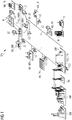
- Fig. 1 shows a schematic representation of the structure of an energy distribution network DN in which a variant of the control method according to the invention is carried out.
- the power distribution network DN is in the right part of the Fig. 1 reproduced and comprises a substation UW and a large number of controllable network nodes N1, N2, ..., N9 and some non-controllable network nodes N '. These network nodes are connected to one another via power lines L.
- the power lines are in Fig. 1 indicated as solid lines and only partially specified with the reference character L.
- there is an exchange of heat between some units in the power distribution network which is shown by dashed lines between the corresponding units. The heat exchange does not play a direct role in the method according to the invention and is therefore not explained further.
- the energy distribution network DN is in particular a medium or low voltage network, the voltage of which is converted by the transformer substation UW into a higher voltage for the transmission network TN.
- Fig. 1 is also another conventional substation UW ', via which a conventional power plant feeds KW power into the transmission network TN.
- a central control unit CO is provided in the substation UW.
- This control unit has the same interfaces to an energy management system of the energy transmission network TN as conventional large power plants. Furthermore, the central control unit communicates with a multiplicity of local control units LC, these local control units being provided in the controllable network nodes N1 to N9 and not in the further non-controllable network nodes N '.
- the communication between the central control unit CO and the local control units LC can be wired or possibly also wirelessly by radio. If necessary, an existing network infrastructure, such as the Internet, can also be used.
- the individual controllable network nodes N1 to N9 are decentralized electrical energy generators or electrical energy stores or transformers or controllable loads.
- the network node N1 represents an industrial photovoltaic system PV
- the network node N2 is an industrial energy wind farm WP
- the network node N3 represents a biomass power plant BM.
- the network nodes N1 to N3 are therefore regenerative energy generation systems.
- network nodes N4 and N5 are fossil-fuel power plants based on combined heat and power.
- the network node N6 is in turn a regenerative energy generation system in the form of a photovoltaic system PV, this system now being installed in a private household.
- a wind turbine for example, can also be used as a regenerative energy generation system.
- the further controllable network node N7 represents an electrical energy store ST, for example in the form of storage batteries.
- the energy distribution network also contains the network node N8, which represents a controllable load LA, which in Fig. 1 is an electric vehicle charging infrastructure.
- the network node N9 is a controllable transformer to convert voltage in the energy distribution network.
- the network nodes N 'do not contain any local control units LC. These can be energy consumers in the form of buildings or households.
- the central control unit CO exchanges information with the local control units LC and with the transmission network TN in order, based thereon, to provide power in the form of active power P and reactive power Q via the coupling point PCC to the transmission network.
- the provision of so-called system services in the form of control power and short-circuit power is also enabled, as is shown by Fig. 2 is explained.
- the energy distribution network DN represents a topological power plant with network nodes in a clearly defined network area and with a clear coupling point to the superimposed energy transmission network.
- Fig. 2 The control shown is based on the principle of adaptive energy control of the document WO 2013/189552 A1 . In addition, the control also enables the above-mentioned system services to be provided.
- Fig. 2 receives a control component CON in the central control unit CO indicated by the dashed rectangle setpoint values SW from the energy transmission network TN.
- the setpoint values SW include, inter alia, the time profile P (t) or Q (t) of the active power or reactive power to be provided by the energy distribution network DN. In other words, schedules for the active power and reactive power generation of the energy distribution network DN are transmitted to the control component CON.
- setpoints for the primary control power PRL, the secondary control power SRL, the control reactive power RBL and the short-circuit power KSL are also specified.
- the variables of the primary control power, secondary control power and short-circuit power are known per se to the person skilled in the art and are therefore not explained in further detail.
- the primary control power is usually controlled by a proportional controller, which provides active power based on fluctuations in the nominal frequency of the network, taking into account a proportionality factor.
- P 0 draws a given active power value
- ⁇ f is the deviation from the nominal frequency
- k f is the mentioned proportionality factor
- the primary control reserve is made available within a few seconds. In contrast to this, a longer period of time is specified for the provision of the secondary control power.
- the short circuit power enables the energy distribution network to provide sufficient current in the event of a short circuit in the energy transmission network, so that the detection of the short circuit is possible via a correspondingly high short circuit current in the transmission network.
- the mentioned control reactive power can be controlled analogously to the primary control power via a proportional controller, but the proportional control now depends on the voltage at the coupling point PCC.
- Q 0 is a specified reactive power value and ⁇ U denotes the deviation of the voltage in the coupling point from a nominal voltage value.
- k U is in turn a proportionality factor of this regulation.
- the component CON carries out the actual control of the energy distribution network and receives the above-mentioned for this purpose Setpoint values SW from the energy transmission network TN. Furthermore, the component CON receives offers AN from the local control units LC of the respective network nodes N1 to N9 for active power P (t), reactive power Q (t) and primary control power PRL, secondary control power SRL, control reactive power BRL and short-circuit power KSL available in the individual network nodes. These offers can be purchased from the control CON for a monetary payment.
- the control component CON processes the setpoint values SW and the offers AN, whereby it also takes into account the results of a network load estimator EST, which is part of the central control unit CO.
- the network load estimator EST uses known methods to estimate the load on the energy distribution network using actual values IW of corresponding parameters from network nodes N1 to N9 or actual values IW (i.e. measured values) of corresponding voltage and / or current sensors SE outside the network nodes.
- the parameters of the network nodes can relate to any power-related variables of the individual network nodes and relate in particular to the active powers, reactive powers, voltages and currents occurring in the individual network nodes.
- These actual values IW are processed by the network load estimator EST in order to thereby determine a network load indication NI which is given to the control component CON. If necessary, there is also the possibility that the network load estimator EST predicts the network load for the future using methods known per se using suitable models and transfers the corresponding forecast value to the control component CON in addition to the network load indicator NI.
- the control component CON takes the network load indicator into account in the control in such a way that a predetermined network load limit is maintained, which, if exceeded, can damage the energy distribution network or lead to a network failure.
- the principle of the control carried out via the component CON taking into account the results of the network load estimator EST, can be found in the above-mentioned publication [2]. Taking recourse the provision of primary control power, secondary control power, control reactive power and short-circuit power is now also taken into account in the process of this publication. An implementation of these additional performance values can be implemented without problems for the person skilled in the art in view of the disclosure of the document [2].
- the power values corresponding to the setpoint values SW are made available for the transmission network TN.
- setpoint values SW 'of the above-mentioned parameters the actual values of which were transmitted to the network load estimator EST, are given to the individual local control units LC.
- the setpoint values SW from the transmission network TN are appropriately divided into setpoint values SW 'for the local network nodes, which are transmitted to the respective local control units. This makes it possible to coordinate the integrated energy producers, energy stores, controllable loads and possibly microgrids in the voltage range of the energy distribution network so that the energy distribution network as a whole participates in the provision of primary control power, secondary control power, control reactive power and short-circuit power and via the simultaneous Avoidance of bottlenecks within the energy distribution network the above-mentioned system services can be reliably provided.
- the classic use cases such as the marketing of electricity products on the electricity market, are covered by processing corresponding timetables.
- the network voltage regulator NVR is optionally provided, which exchanges information with the network load estimator EST in order to determine the voltage in the power distribution network in a suitable manner.
- the network voltage regulator NVR receives control parameters RP, such as reactive power setpoints, from the control component CON and uses them to calculate control values or setpoint values RW for the voltage regulation, which are then passed on to the local controls LC of the network nodes N1 to N9 or to the voltage regulators VC, which are again shown separately
- the voltage regulators can represent, among other things, transformers TR or possibly also capacitance banks KB.
- the embodiment of the invention described above has a number of advantages.
- the control of an energy distribution network is created in such a way that the energy distribution network represents a topological power plant up to the transmission network, which for the first time enables the full system integration of decentralized systems including their participation in all relevant system services (in particular the provision of primary control power, secondary control power and short-circuit power).
Description
Die Erfindung betrifft ein Verfahren zur Steuerung eines elektrischen Energieverteilnetzes sowie ein entsprechendes Energieverteilnetz und eine Steuereinheit.The invention relates to a method for controlling an electrical energy distribution network as well as a corresponding energy distribution network and a control unit.
Aus dem Stand der Technik sind Ansätze bekannt, mit denen die Bereitstellung von Leistung durch Energieverteilnetze mit dezentralen Energieerzeugern für ein daran gekoppeltes Energieübertragungsnetz geeignet gesteuert wird. In der Druckschrift [1] wird das Konzept eines sog. virtuellen Kraftwerks beschrieben, bei dem die Informationen von dezentralen Energieerzeugern eines Energieverteilnetz in einer zentralen Steuereinheit aggregiert werden, die mit einem Energieübertragungsnetz kommuniziert, so dass das Energieverteilnetz gegenüber dem Energieübertragungsnetz als ein einzelnes virtuelles Kraftwerk fungiert. Dieses Kraftwerk stellt dem Energieübertragungsnetz Wirkleistung bzw. Blindleistung bereit, beschreibt jedoch kein vollumfängliches Konzept, um wesentliche Systemdienstleistungen für das Energieübertragungsnetz zu realisieren.Approaches are known from the prior art with which the provision of power through energy distribution networks with decentralized energy generators is suitably controlled for an energy transmission network coupled thereto. In the document [1] the concept of a so-called virtual power plant is described, in which the information from decentralized energy producers of an energy distribution network is aggregated in a central control unit that communicates with an energy transmission network, so that the energy distribution network compared to the energy transmission network as a single virtual power plant acts. This power plant provides active power or reactive power to the energy transmission network, but does not describe a comprehensive concept for realizing essential system services for the energy transmission network.
In der Druckschrift [2] wird ein Energiezuteilungsverfahren beschrieben, bei dem eine adaptive Energiesteuerung von Energiequellen und Verbrauchern mittels einer Zuteilungskomponente und einer Netzüberwachungskomponente durchgeführt wird. Die Netzüberwachungskomponente überprüft eine Machbarkeit der von der Zuteilungskomponente ermittelten Energiezuteilung.In the document [2], an energy allocation method is described in which an adaptive energy control of energy sources and consumers is carried out by means of an allocation component and a network monitoring component. The network monitoring component checks the feasibility of the energy allocation determined by the allocation component.
Aufgabe der Erfindung ist es, ein Verfahren zur Steuerung eines elektrischen Energieverteilnetzes zu schaffen, welches die Bereitstellung von wesentlichen Systemdienstleistungen für ein Energieübertragungsnetz ermöglicht.The object of the invention is to create a method for controlling an electrical energy distribution network which enables the provision of essential system services for an energy transmission network.
Diese Aufgabe wird durch das Verfahren gemäß Patentanspruch 1 gelöst. Weiterbildungen der Erfindung sind in den abhängigen Ansprüchen definiert.This object is achieved by the method according to claim 1. Developments of the invention are defined in the dependent claims.
Das erfindungsgemäße Verfahren dient zur Steuerung eines elektrischen Energieverteilnetzes, in dem elektrische Leistung bzw. Energie über eine Vielzahl von über Stromleitungen verbundenen Netzknoten bereitgestellt wird. Der Begriff der elektrischen Leistung umfasst sowohl Wirkleistung als auch Blindleistung. Zumindest ein Teil der Netzknoten sind steuerbare Netzknoten mit jeweiligen lokalen Steuereinheiten. Ferner sind zumindest ein Teil dieser steuerbaren Netzknoten dezentrale elektrische Energieerzeuger, welche entsprechende Leistung generieren. Gegebenenfalls können in dem Energieverteilnetz auch einer oder mehrere der steuerbaren Netzknoten keine Energieerzeuger sein. Solche Netzknoten können beispielsweise steuerbare dezentrale elektrische Energieverbraucher oder Spannungsregler darstellen. Beispiele für Varianten von steuerbaren Netzknoten werden weiter unten gegeben.The method according to the invention is used to control an electrical energy distribution network in which electrical power or energy is provided via a large number of network nodes connected via power lines. The term electrical power includes both real and reactive power. At least some of the network nodes are controllable network nodes with respective local control units. Furthermore, at least some of these controllable network nodes are decentralized electrical energy generators, which generate corresponding power. If necessary, one or more of the controllable network nodes in the energy distribution network can also not be energy producers. Such network nodes can represent controllable decentralized electrical energy consumers or voltage regulators, for example. Examples of variants of controllable network nodes are given below.
Das Energieverteilnetz ist an einem Koppelpunkt (englisch: Point of Common Coupling) an ein Energieübertragungsnetz gekoppelt und stellt an diesem Koppelpunkt dem Energieübertragungsnetz elektrische Leistung bereit, die von den steuerbaren Netzknoten des Energieverteilnetzes stammt. Gegebenenfalls können mehrere solcher Koppelpunkte vorgesehen sein. Zur Bereitstellung der elektrischen Leistung kommuniziert eine zentrale Steuereinheit im Energieverteilnetz mit den lokalen Steuereinheiten der steuerbaren Netzknoten und dem Energieübertragungsnetz (bzw. einer entsprechenden Steuerkomponente dieses Energieübertragungsnetzes).The energy distribution network is coupled to an energy transmission network at a coupling point (point of common coupling) and at this coupling point provides the energy transmission network with electrical power that comes from the controllable network nodes of the energy distribution network. If necessary, several such crosspoints can be provided. To provide the electrical power, a central control unit in the energy distribution network communicates with the local control units of the controllable network nodes and the energy transmission network (or a corresponding control component of this energy transmission network).
Das erfindungsgemäße Verfahren zeichnet sich dadurch aus, dass die zentrale Steuereinheit das Energieverteilnetz, das ein topologisches Kraftwerk mit den Netzknoten in einem klar definierten Netzgebiet und mit dem Koppelpunkt als eindeutigen Koppelpunkt zum überlagerten Energieübertragungsnetz darstellt, mit Hilfe der Kommunikation mit den lokalen Steuereinheiten und dem Energieübertragungsnetz derart steuert, dass an dem eindeutigen Koppelpunkt Primärregelleistung und Kurzschlussleistung für das Energieübertragungsnetz vorgehalten wird. Das erfindungsgemäße Verfahren ermöglicht somit erstmalig die Bereitstellung wesentlicher Systemdienstleistungen in der Form von Primärregelleistung und Kurzschlussleistung. Diese Leistungsarten sind an sich bekannt. Die Primärregelleistung dient zur Aufrechterhaltung der Netzfrequenz und die Kurzschlussleistung ermöglicht einen hohen Strom beim Auftreten eines Kurzschlusses im Energieübertragungsnetz. Üblicherweise wird die Primärregelleistung basierend auf einer Proportionalregelung in Abhängigkeit von Frequenzschwankungen bereitgestellt, wie weiter unten näher erläutert wird.The method according to the invention is characterized in that the central control unit represents the energy distribution network, which is a topological power plant with the network nodes in a clearly defined network area and with the coupling point as a clear coupling point to the superimposed energy transmission network, using communication with the local control units and controls the energy transmission network in such a way that primary control power and short-circuit power for the energy transmission network are held at the unique coupling point. The method according to the invention thus makes it possible for the first time to provide essential system services in the form of primary control power and short-circuit power. These types of services are known per se. The primary control power is used to maintain the network frequency and the short-circuit power enables a high current in the event of a short circuit in the energy transmission network. The primary control power is usually provided based on proportional control as a function of frequency fluctuations, as will be explained in more detail below.
In einer weiteren Variante des erfindungsgemäßen Verfahrens steuert die zentrale Steuereinheit das Energieverteilnetz ferner derart, dass am Koppelpunkt Sekundärregelleistung und/oder Tertiärregelleistung für das Energieübertragungsnetz vorgehalten wird und/oder dass Oberwellen und/oder Subharmonische der Spannung am Koppelpunkt kompensiert werden. Mit dieser Variante werden somit noch weitergehende Systemdienstleistungen durch das Energieverteilnetz bereitgestellt.In a further variant of the method according to the invention, the central control unit also controls the energy distribution network in such a way that secondary control power and / or tertiary control power for the energy transmission network is provided at the coupling point and / or that harmonics and / or subharmonics of the voltage at the coupling point are compensated. With this variant, even more extensive system services are provided by the energy distribution network.
In einer weiteren Ausgestaltung des erfindungsgemäßen Verfahrens steuert die zentrale Steuereinheit das Energieverteilnetz ferner derart, dass am Koppelpunkt als weitere Systemdienstleistung Blindleistung für das Energieübertragungsnetz vorgehalten wird, wobei diese Blindleistung bei Bedarf Spannungsschwankungen am Koppelpunkt kompensieren kann. Diese Art der Blindleistungsbereitstellung entspricht vom Regelungs- und Wirkprinzip der sog. Primärregelleistung, die als Wirkleistung die Frequenz beeinflusst. Wegen der Analogie wird im Folgenden der Begriff der "Regelblindleistung" benutzt. Die Regelblindleistung kann ähnlich wie die Primärregelleistung basierend auf einer Proportionalregelung bereitgestellt werden, wobei diese Proportionalregelung nunmehr von Spannungsschwankungen am Koppelpunkt abhängt.In a further embodiment of the method according to the invention, the central control unit also controls the energy distribution network in such a way that reactive power for the energy transmission network is held as a further system service at the coupling point, this reactive power being able to compensate for voltage fluctuations at the coupling point if necessary. This type of reactive power provision corresponds to the control and active principle of the so-called primary control power, which influences the frequency as active power. Because of the analogy, the term "control reactive power" is used in the following. Similar to the primary control power, the control reactive power can be provided based on a proportional control, this proportional control now being dependent on voltage fluctuations at the coupling point.
In einer weiteren Ausgestaltung des erfindungsgemäßen Verfahrens steuert die zentrale Steuereinheit das Energieverteilnetz ferner derart, dass es bei Ausfall des Energieübertragungsnetzes als Inselnetz betrieben wird. Insbesondere übernimmt die zentrale Steuereinheit auch eine Resynchronisation des Energieverteilnetzes mit dem Energieübertragungsnetz, wenn dieses den Betrieb wieder aufnimmt. Gemäß der soeben beschriebenen Variante wird die weitergehende Systemdienstleistung der Schwarzstartfähigkeit bereitgestellt.In a further embodiment of the method according to the invention, the central control unit also controls the energy distribution network in such a way that, if the energy transmission network fails is operated as an island network. In particular, the central control unit also resynchronizes the energy distribution network with the energy transmission network when it resumes operation. According to the variant just described, the more extensive system service of black start capability is provided.
In einem weiteren Ausführungsbeispiel werden im Rahmen der Kommunikation der zentralen Steuereinheit mit dem Energieübertragungsnetz Sollwerte für die vorzuhaltende Primärregelleistung und Kurzschlussleistung und ggf. auch für die oben beschriebene vorzuhaltende Sekundärregelleistung bzw. Tertiärregelleistung bzw. Regelblindleistung von dem Energieübertragungsnetz an die zentrale Steuereinheit übermittelt. Alternativ oder zusätzlich werden im Rahmen der Kommunikation der zentralen Steuereinheit mit den lokalen Steuereinheiten die von den steuerbaren Netzknoten jeweils angebotene Primärregelleistung und Kurzschlussleistung und ggf. auch die jeweils angebotene Sekundärregelleistung bzw. Tertiärregelleistung bzw. Regelblindleistung durch die lokalen Steuereinheiten der zentralen Steuereinheit mitgeteilt. Mit diesen ausgetauschten Informationen kann bedarfsgerecht die entsprechende Systemdienstleistung dem Energieübertragungsnetz bereitgestellt werden.In a further exemplary embodiment, as part of the communication between the central control unit and the energy transmission network, setpoint values for the primary control power and short-circuit power to be kept available and, if necessary, also for the secondary control power or tertiary control power or reactive control power described above are transmitted from the energy transmission network to the central control unit. Alternatively or additionally, as part of the communication between the central control unit and the local control units, the primary control power and short-circuit power offered by the controllable network nodes and possibly also the respective secondary control power or tertiary control power or control reactive power offered by the local control units are communicated to the central control unit. With this exchanged information, the corresponding system service can be provided to the energy transmission network as required.
In einer besonders bevorzugten Ausführungsform wird in der zentralen Steuereinheit die aktuelle Netzbelastung des Energieverteilnetzes geschätzt und/oder die zukünftige Netzbelastung vorhergesagt, wobei die zentrale Steuereinheit bei der Steuerung des Energieverteilnetzes die aktuelle und/oder zukünftige Netzbelastung derart berücksichtigt, dass eine bestimmte Belastungsgrenze des Energieverteilnetzes nicht überschritten wird.In a particularly preferred embodiment, the current network load of the energy distribution network is estimated in the central control unit and / or the future network load is predicted, the central control unit taking into account the current and / or future network load when controlling the energy distribution network in such a way that a certain load limit of the energy distribution network is not is exceeded.
In einer speziellen Variante der soeben beschriebenen Ausführungsform werden zur Schätzung der aktuellen Netzbelastung und/oder zur Vorhersage der zukünftigen Netzbelastung Istwerte und/oder Vorhersagen von Parametern der steuerbaren Netzknoten von den jeweiligen lokalen Steuereinheiten an die zentrale Steuereinheit übermittelt. Basierend auf der (geschätzten) aktuellen bzw. (vorgesagten) zukünftigen Netzbelastung werden Sollwerte der Parameter der steuerbaren Netzknoten von der zentralen Steuereinheit an die jeweiligen Steuereinheiten übermittelt. Die Parameter, deren Ist- bzw. Sollwerte übermittelt werden, können je nach Ausgestaltung des Verfahrens unterschiedlich sein. Insbesondere betreffen sie Spannungen bzw. Ströme bzw. Wirk- und Blindleistungen in den jeweiligen steuerbaren Netzknoten.In a special variant of the embodiment just described, actual values and / or predictions of parameters of the controllable network nodes are used to estimate the current network load and / or to predict the future network load transmitted from the respective local control units to the central control unit. Based on the (estimated) current or (predicted) future network load, setpoint values of the parameters of the controllable network nodes are transmitted from the central control unit to the respective control units. The parameters whose actual or setpoint values are transmitted can be different depending on the design of the method. In particular, they relate to voltages or currents or active and reactive powers in the respective controllable network nodes.
In einer weiteren Variante des erfindungsgemäßen Verfahrens werden zur Schätzung der aktuellen Netzbelastung und/oder zur Vorhersage der zukünftigen Netzbelastung ferner Istwerte von Spannungs- und/oder Stromsensoren, die im Energieverteilnetz außerhalb der steuerbaren Netzknoten angeordnet sind, und/oder Wettervorhersagen an die zentrale Steuereinheit übermittelt. Aus den Wettervorhersagen kann die zentrale Steuereinheit Vorhersagen für Parameter des Verteilnetzes ermitteln, z.B. den Verbrauch oder die Erzeugung von erneuerbarer Energie. Insbesondere die Wettervorhersagen können ggf. auch an die lokalen Steuereinheiten übermittelt werden, die daraus eine Vorhersage des eigenen Verbrauchs oder der eigenen Erzeugung ermitteln.In a further variant of the method according to the invention, actual values from voltage and / or current sensors, which are arranged in the energy distribution network outside the controllable network nodes, and / or weather forecasts are transmitted to the central control unit to estimate the current network load and / or to predict the future network load . The central control unit can use the weather forecasts to determine forecasts for parameters of the distribution network, e.g. consumption or generation of renewable energy. In particular, the weather forecasts can optionally also be transmitted to the local control units, which use them to determine a forecast of their own consumption or their own generation.
In einer weiteren Ausgestaltung der Erfindung ist der Koppelpunkt an einem Umspannwerk vorgesehen, wobei die zentrale Steuereinheit im Umspannwerk angeordnet sein kann, aber nicht muss. Insbesondere umfasst das Energieverteilnetz ein Niederspannungs- oder Mittelspannungsnetz, dessen Spannung über das Umspannwerk in eine höhere Spannung des Energieübertragungsnetzes transformiert wird.In a further embodiment of the invention, the coupling point is provided at a substation, wherein the central control unit can be arranged in the substation, but does not have to be. In particular, the energy distribution network comprises a low-voltage or medium-voltage network, the voltage of which is transformed into a higher voltage of the energy transmission network via the substation.
In einer weiteren Variante umfassen die steuerbaren Netzknoten des Energieverteilnetzes, welche Energieerzeuger sind, eine oder mehrere regenerative Energieerzeuger, insbesondere eine oder mehrere Windkraftanlagen und/oder eine oder mehrere Photovoltaikanlagen und/oder ein oder mehrere Wasserkraftwerke und/oder ein oder mehrere Biomassekraftwerke mit jeweiligen lokalen Steuereinheiten. Ebenso können die steuerbaren Netzknoten eine oder mehrere fossile Kraftwerke und/oder eine oder mehrere Kraft-Wärme-Kopplungs-Anlagen bzw. Kraft-Wärme-Kälte-Kopplungs-Anlagen mit jeweiligen lokalen Steuereinheiten umfassen. Alle lokalen Steuereinheiten der genannten steuerbaren Netzknoten kommunizieren im Rahmen der Steuerung des Energieverteilnetzes mit der zentralen Steuereinheit und sind somit in das erfindungsgemäße Steuerverfahren einbezogen.In a further variant, the controllable network nodes of the energy distribution network, which are energy producers, include one or more regenerative energy producers, in particular one or more wind power plants and / or one or more photovoltaic plants and / or one or more hydropower plants and / or one or more biomass power plants with respective local control units. Likewise, the controllable network nodes can include one or more fossil fuel power plants and / or one or more combined heat and power plants or combined heat and power plants with respective local control units. All local control units of the aforementioned controllable network nodes communicate with the central control unit within the scope of controlling the energy distribution network and are thus included in the control method according to the invention.
In einer weiteren bevorzugten Ausführungsform umfassen die steuerbaren Netzknoten des Energieverteilnetzes neben Energieerzeugern einen oder mehrere steuerbare elektrische Energieverbraucher und/oder einen oder mehrere elektrische Energiespeicher und/oder ein oder mehrere Microgrids mit jeweiligen lokalen Steuereinheiten. Diese lokalen Steuereinheiten kommunizieren im Rahmen der Steuerung des Energieverteilnetzes mit der zentralen Steuereinheit und sind somit in das erfindungsgemäße Steuerverfahren einbezogen.In a further preferred embodiment, the controllable network nodes of the energy distribution network include, in addition to energy generators, one or more controllable electrical energy consumers and / or one or more electrical energy stores and / or one or more microgrids with respective local control units. These local control units communicate with the central control unit as part of the control of the energy distribution network and are thus included in the control method according to the invention.
In einer weiteren Ausgestaltung des erfindungsgemäßen Verfahrens umfassen die steuerbaren Netzknoten des Energieverteilnetzes ferner einen oder mehrere Spannungsregler mit jeweiligen lokalen Steuereinheiten, welche im Rahmen der Steuerung des Energieverteilnetzes mit der zentralen Steuereinheit kommunizieren und somit ebenfalls in das erfindungsgemäße Steuerverfahren einbezogen sind. Der oder die Spannungsregler umfassen vorzugsweise einen oder mehrere Transformatoren und/oder eine oder mehrere Kapazitätsbänke und/oder einen oder mehrere Längsregler.In a further embodiment of the method according to the invention, the controllable network nodes of the energy distribution network also include one or more voltage regulators with respective local control units, which communicate with the central control unit as part of the control of the energy distribution network and are thus also included in the control method according to the invention. The voltage regulator or regulators preferably comprise one or more transformers and / or one or more capacitance banks and / or one or more series regulators.
Neben dem oben beschriebenen Verfahren betrifft die Erfindung ferner ein elektrisches Energieverteilnetz, welches zur Bereitstellung von elektrischer Leistung eine Vielzahl von über Stromleitungen verbundene Netzknoten umfasst, wobei zumindest ein Teil der Netzknoten steuerbare Netzknoten mit jeweiligen lokalen Steuereinheiten sind und zumindest ein Teil dieser steuerbaren Netzknoten dezentrale elektrische Energieerzeuger oder dezentrale elektrische Energiespeicher sind. Das Energieverteilnetz ist an einem Koppelpunkt an ein Energieübertragungsnetz gekoppelt und kann an diesem Koppelpunkt dem Energieübertragungsnetz elektrische Leistung bereitstellen, die von den steuerbaren Netzknoten des Energieverteilnetzes stammt. Zur Bereitstellung der elektrischen Leistung kann eine zentrale Steuereinheit in dem Energieverteilnetz mit den lokalen Steuereinheiten der steuerbaren Netzknoten und dem Energieübertragungsnetz kommunizieren.In addition to the method described above, the invention also relates to an electrical power distribution network which comprises a plurality of network nodes connected via power lines to provide electrical power, at least some of the network nodes being controllable network nodes with respective local control units and at least some of these controllable network nodes are decentralized electrical energy generators or decentralized electrical energy stores. The energy distribution network is coupled to an energy transmission network at a coupling point and at this coupling point can provide the energy transmission network with electrical power that originates from the controllable network nodes of the energy distribution network. To provide the electrical power, a central control unit in the energy distribution network can communicate with the local control units of the controllable network nodes and the energy transmission network.
Das erfindungsgemäße elektrische Energieverteilnetz zeichnet sich dadurch aus, dass die zentrale Steuereinheit derart ausgestaltet ist, dass sie das Energieverteilnetz, das ein topologisches Kraftwerk mit den Netzknoten in einem klar definierten Netzgebiet und mit dem Koppelpunkt als eindeutigen Koppelpunkt zum überlagerten Energieübertragungsnetz darstellt, mit Hilfe der Kommunikation mit den lokalen Steuereinheiten und dem Energieübertragungsnetz derart steuert, dass an dem eindeutigen Koppelpunkt Primärregelleistung und Kurzschlussleistung für das Energieübertragungsnetz vorgehalten wird.The electrical energy distribution network according to the invention is characterized in that the central control unit is designed in such a way that it represents the energy distribution network, which is a topological power plant with the network nodes in a clearly defined network area and with the coupling point as a clear coupling point to the superimposed energy transmission network, with the aid of communication controls with the local control units and the energy transmission network in such a way that primary control power and short-circuit power for the energy transmission network are kept at the clear coupling point.
Vorzugsweise ist das erfindungsgemäße Energieverteilnetz zur Ausführung einer oder mehrerer bevorzugter Varianten des erfindungsgemäßen Verfahrens eingerichtet.The energy distribution network according to the invention is preferably set up to carry out one or more preferred variants of the method according to the invention.
Die Erfindung betrifft darüber hinaus eine Steuereinheit für das soeben beschriebene elektrische Energieverteilnetz. Die Steuereinheit stellt die oben erläuterte zentrale Steuereinheit des Energieverteilnetzes dar, welche derart ausgestaltet ist, dass sie mit den lokalen Steuereinheiten der steuerbaren Netzknoten, die dezentrale elektrische Energieerzeuger oder dezentrale elektrische Energiespeicher sind, und dem Energieübertragungsnetz kommuniziert und mit Hilfe dieser Kommunikation das Energieverteilnetz, das ein topologisches Kraftwerk mit den Netzknoten in einem klar definierten Netzgebiet und mit dem Koppelpunkt als eindeutigen Koppelpunkt zum überlagerten Energieübertragungsnetz darstellt, derart steuert, dass an dem eindeutigen Koppelpunkt Primärregelleistung und Kurzschlussleistung für das Energieübertragungsnetz vorgehalten wird. Jeweilige Merkmale der oben beschriebenen bevorzugten Varianten des erfindungsgemäßen Verfahrens, die mit der Steuereinheit im Zusammenhang stehen, können in der Form entsprechender Vorrichtungsmerkmale in der Steuereinheit implementiert sein.The invention also relates to a control unit for the electrical power distribution network just described. The control unit represents the central control unit of the energy distribution network explained above, which is designed in such a way that it communicates with the local control units of the controllable network nodes, which are decentralized electrical energy generators or decentralized electrical energy stores, and the energy transmission network and, with the help of this communication, the energy distribution network, which a topological power plant with the network nodes in a clearly defined network area and with the coupling point as a unique coupling point to the superimposed energy transmission network, controls in such a way that primary control power and short-circuit power for the energy transmission network are kept at the unique coupling point. Respective features of the above-described preferred variants of the method according to the invention, which are related to the control unit, can be implemented in the control unit in the form of corresponding device features.
Ausführungsbeispiele der Erfindung werden nachfolgend anhand der beigefügten Figuren detailliert beschrieben.Exemplary embodiments of the invention are described in detail below with reference to the accompanying figures.
Es zeigen:
- Fig. 1
- eine schematische Darstellung eines Energieverteilnetzes, in dem eine Variante des erfindungsgemäßen Steuerverfahrens durchgeführt wird; und
- Fig. 2
- ein Diagramm, welches den Ablauf einer Variante des erfindungsgemäßen Verfahrens in dem Energieverteilnetz der
Fig. 1 wiedergibt.
- Fig. 1
- a schematic representation of an energy distribution network in which a variant of the control method according to the invention is carried out; and
- Fig. 2
- a diagram showing the sequence of a variant of the method according to the invention in the energy distribution network of
Fig. 1 reproduces.
Das Umspannwerk UW des Energieverteilnetzes DN ist über einen Koppelpunkt PCC (PCC = Point of Common Coupling) mit einem lediglich schematisch angedeuteten Energieübertragungsnetz TN gekoppelt. Über diesen Koppelpunkt wird Wirkleistung P und Blindleistung Q in das Übertragungsnetz eingespeist. Das Energieverteilnetz DN ist insbesondere ein Mittel- bzw. Niederspannungsnetz, dessen Spannung durch das Umspannwerk UW in eine höhere Spannung für das Übertragungsnetz TN gewandelt wird. In
Zur Realisierung des erfindungsgemäßen Steuerverfahrens ist im Umspannwerk UW eine zentrale Steuereinheit CO vorgesehen. Diese Steuereinheit hat die gleichen Schnittstellen zu einem Energie-Management-System des Energieübertragungsnetzes TN wie herkömmliche Großkraftwerke. Ferner kommuniziert die zentrale Steuereinheit mit einer Vielzahl von lokalen Steuereinheiten LC, wobei diese lokalen Steuereinheiten in den steuerbaren Netzknoten N1 bis N9 und nicht in den weiteren nicht steuerbaren Netzknoten N' vorgesehen sind. Die Kommunikation zwischen der zentralen Steuereinheit CO und den lokalen Steuereinheiten LC kann drahtgebunden oder ggf. auch drahtlos per Funk erfolgen. Dabei kann ggf. auch eine bereits vorhandene Netzinfrastruktur, wie z.B. das Internet, genutzt werden.To implement the control method according to the invention, a central control unit CO is provided in the substation UW. This control unit has the same interfaces to an energy management system of the energy transmission network TN as conventional large power plants. Furthermore, the central control unit communicates with a multiplicity of local control units LC, these local control units being provided in the controllable network nodes N1 to N9 and not in the further non-controllable network nodes N '. The communication between the central control unit CO and the local control units LC can be wired or possibly also wirelessly by radio. If necessary, an existing network infrastructure, such as the Internet, can also be used.
Bei den einzelnen steuerbaren Netzknoten N1 bis N9 handelt es sich um dezentrale elektrische Energieerzeuger bzw. elektrische Energiespeicher bzw. Transformatoren bzw. steuerbare Lasten. Im Einzelnen stellt der Netzknoten N1 eine industrielle Photovoltaikanlage PV dar, der Netzknoten N2 ist ein industrieller Energiewindpark WP und der Netzknoten N3 repräsentiert ein Biomassekraftwerk BM. Bei den Netzknoten N1 bis N3 handelt es sich somit um regenerative Energieerzeugungsanlagen. Demgegenüber sind die Netzknoten N4 und N5 fossile Kraftwerke KWK, die auf Kraft-Wärme-Kopplung basieren. Der Netzknoten N6 ist wiederum eine regenerative Energieerzeugungsanlage in der Form einer Photovoltaikanlage PV, wobei diese Anlage nunmehr in einem privaten Haushalt installiert ist. Anstatt einer Photovoltaikanlage kann als regenerative Energieerzeugungsanlage z.B. auch eine Windkraftanlage verwendet werden.The individual controllable network nodes N1 to N9 are decentralized electrical energy generators or electrical energy stores or transformers or controllable loads. In detail, the network node N1 represents an industrial photovoltaic system PV, the network node N2 is an industrial energy wind farm WP and the network node N3 represents a biomass power plant BM. The network nodes N1 to N3 are therefore regenerative energy generation systems. In contrast, network nodes N4 and N5 are fossil-fuel power plants based on combined heat and power. The network node N6 is in turn a regenerative energy generation system in the form of a photovoltaic system PV, this system now being installed in a private household. Instead of a photovoltaic system, a wind turbine, for example, can also be used as a regenerative energy generation system.
Der weitere steuerbare Netzknoten N7 stellt einen elektrischen Energiespeicher ST dar, z.B. in der Form von Speicherbatterien. Ferner enthält das Energieverteilnetz den Netzknoten N8, der eine steuerbare Last LA darstellt, die in
Die zentrale Steuereinheit CO tauscht Informationen mit den lokalen Steuereinheiten LC und mit dem Übertragungsnetz TN aus, um basierend darauf Leistung in der Form von Wirkleistung P und Blindleistung Q über den Koppelpunkt PCC dem Übertragungsnetz bereitzustellen. Dabei wird auch die Bereitstellung von sog. Systemdienstleistungen in der Form von Regelleistung und Kurzschlussleistung ermöglicht, wie anhand von
Die in
Neben diesen Fahrplänen werden zusätzlich Sollwerte für die Primärregelleistung PRL, die Sekundärregelleistung SRL, die Regelblindleistung RBL und die Kurzschlussleistung KSL vorgegeben. Die Größen der Primärregelleistung, Sekundärregelleistung und Kurzschlussleistung sind dem Fachmann an sich bekannt und werden deshalb nicht weiter im Detail erläutert. Die Primärregelleistung wird meist über einen Proportionalregler gesteuert, der Wirkleistung basierend auf Schwankungen der Nennfrequenz des Netzes unter Berücksichtigung eines Proportionalitätsfaktors bereitstellt. Im Speziellen kann die Primärregelleistung mit einem Proportionalregler wie folgt eingestellt werden: ![]()
![]()
Dabei zeichnet P0 einen vorgegebenen Wirkleistungswert, Δf ist die Abweichung von der Nennfrequenz und kf ist der erwähnte Proportionalitätsfaktor.P 0 draws a given active power value, Δf is the deviation from the nominal frequency and k f is the mentioned proportionality factor.
Die Primärregelleistung wird innerhalb einiger Sekunden bereitgestellt. Im Gegensatz hierzu ist ein längerer Zeitraum für die Bereitstellung der Sekundärregelleistung festgelegt. Die Kurzschlussleistung ermöglicht, dass das Energieverteilnetz ausreichend Strom im Falle eines Kurzschlusses im Energieübertragungsnetz bereitstellt, so dass die Detektion des Kurzschlusses über einen entsprechend hohen Kurzschlussstrom im Übertragungsnetz möglich ist.The primary control reserve is made available within a few seconds. In contrast to this, a longer period of time is specified for the provision of the secondary control power. The short circuit power enables the energy distribution network to provide sufficient current in the event of a short circuit in the energy transmission network, so that the detection of the short circuit is possible via a correspondingly high short circuit current in the transmission network.
Die erwähnte Regelblindleistung kann analog zur Primärregelleistung über einen Proportionalregler gesteuert werden, wobei die Proportionalregelung nunmehr jedoch von der Spannung am Koppelpunkt PCC abhängt. Im Speziellen lautet die Proportionalregelung in einem solchen Regler wie folgt: ![]()
![]()
Q0 ist ein vorgegebener Blindleistungswert und ΔU bezeichnet die Abweichung der Spannung im Koppelpunkt von einem Nennspannungswert. kU ist wiederum ein Proportionalitätsfaktor dieser Regelung.Q 0 is a specified reactive power value and ΔU denotes the deviation of the voltage in the coupling point from a nominal voltage value. k U is in turn a proportionality factor of this regulation.
Die Komponente CON führt die eigentliche Steuerung des Energieverteilnetzes aus und empfängt hierzu die oben erwähnten Sollwerte SW von dem Energieübertragungsnetz TN. Ferner erhält die Komponente CON von den lokalen Steuereinheiten LC der jeweiligen Netzknoten N1 bis N9 Angebote AN für in den einzelnen Netzknoten verfügbare Wirkleistung P(t), Blindleistung Q(t) sowie Primärregelleistung PRL, Sekundärregelleistung SRL, Regelblindleistung BRL und Kurzschlussleistung KSL. Diese Angebote können von der Steuerung CON gegen eine monetäre Zahlung erworben werden. Die Steuerkomponente CON verarbeitet die Sollwerte SW sowie die Angebote AN, wobei sie auch noch die Ergebnisse eines Netzbelastungsschätzers EST berücksichtigt, der Teil der zentralen Steuereinheit CO ist.The component CON carries out the actual control of the energy distribution network and receives the above-mentioned for this purpose Setpoint values SW from the energy transmission network TN. Furthermore, the component CON receives offers AN from the local control units LC of the respective network nodes N1 to N9 for active power P (t), reactive power Q (t) and primary control power PRL, secondary control power SRL, control reactive power BRL and short-circuit power KSL available in the individual network nodes. These offers can be purchased from the control CON for a monetary payment. The control component CON processes the setpoint values SW and the offers AN, whereby it also takes into account the results of a network load estimator EST, which is part of the central control unit CO.
Der Netzbelastungsschätzer EST schätzt mittels bekannter Methoden die Belastung des Energieverteilnetzes unter Verwendung von Istwerten IW entsprechender Parameter der Netzknoten N1 bis N9 bzw. von Istwerten IW (d.h. Messwerten) entsprechender Spannungs- und/oder Stromsensoren SE außerhalb der Netzknoten. Die Parameter der Netzknoten können beliebige stromtechnische Größen der einzelnen Netzknoten betreffen und beziehen sich insbesondere auf die auftretenden Wirkleistungen, Blindleistungen, Spannungen und Ströme in den einzelnen Netzknoten. Diese Istwerte IW werden von dem Netzbelastungsschätzer EST verarbeitet, um hierdurch einen Netzlastindikation NI zu ermitteln, der an die Steuerkomponente CON gegeben wird. Gegebenenfalls besteht auch die Möglichkeit, dass der Netzbelastungsschätzer EST mit an sich bekannten Verfahren über geeignete Modelle die Netzbelastung für die Zukunft vorhersagt und den entsprechenden Vorhersagewert neben dem Netzlastindikator NI an die Steuerkomponente CON übergibt.The network load estimator EST uses known methods to estimate the load on the energy distribution network using actual values IW of corresponding parameters from network nodes N1 to N9 or actual values IW (i.e. measured values) of corresponding voltage and / or current sensors SE outside the network nodes. The parameters of the network nodes can relate to any power-related variables of the individual network nodes and relate in particular to the active powers, reactive powers, voltages and currents occurring in the individual network nodes. These actual values IW are processed by the network load estimator EST in order to thereby determine a network load indication NI which is given to the control component CON. If necessary, there is also the possibility that the network load estimator EST predicts the network load for the future using methods known per se using suitable models and transfers the corresponding forecast value to the control component CON in addition to the network load indicator NI.
Die Steuerkomponente CON berücksichtigt den Netzlastindikator bei der Steuerung derart, dass eine vorbestimmte Netzbelastungsgrenze eingehalten wird, bei deren Überschreiten das Energieverteilnetz beschädigt werden kann bzw. es zu einem Ausfall des Netzes kommen kann. Das Prinzip der über die Komponente CON durchgeführten Steuerung unter Berücksichtigung der Ergebnisse des Netzbelastungsschätzers EST kann der oben genannten Druckschrift [2] entnommen werden. Unter Rückgriff auf das Verfahren dieser Druckschrift wird nunmehr auch die Bereitstellung von Primärregelleistung, Sekundärregelleistung, Regelblindleistung und Kurzschlussleistung berücksichtigt wird. Eine Implementierung dieser zusätzlichen Leistungswerte ist angesichts der Offenbarung der Druckschrift [2] für den Fachmann problemlos umsetzbar.The control component CON takes the network load indicator into account in the control in such a way that a predetermined network load limit is maintained, which, if exceeded, can damage the energy distribution network or lead to a network failure. The principle of the control carried out via the component CON, taking into account the results of the network load estimator EST, can be found in the above-mentioned publication [2]. Taking recourse the provision of primary control power, secondary control power, control reactive power and short-circuit power is now also taken into account in the process of this publication. An implementation of these additional performance values can be implemented without problems for the person skilled in the art in view of the disclosure of the document [2].
Als Ergebnis der über die Komponente CON durchgeführten Steuerung werden die Leistungswerte entsprechend der Sollwerte SW für das Übertragungsnetz TN bereitgestellt. Um dies zu erreichen, werden Sollwerte SW' der oben genannten Parameter, deren Istwerte an den Netzbelastungsschätzer EST übertragen wurden, an die einzelnen lokalen Steuereinheiten LC gegeben. Durch die Einstellung der Parameter auf die entsprechenden Sollwerte SW' wird gleichzeitig sichergestellt, dass es nicht zu einer Netzüberlastung kommt.As a result of the control carried out via the component CON, the power values corresponding to the setpoint values SW are made available for the transmission network TN. In order to achieve this, setpoint values SW 'of the above-mentioned parameters, the actual values of which were transmitted to the network load estimator EST, are given to the individual local control units LC. By setting the parameters to the corresponding setpoints SW ', it is ensured at the same time that there is no network overload.
Über die Steuerkomponente CON in Kombination mit dem Netzbelastungsschätzer EST können drohende Engpässe innerhalb des Energieverteilnetzes erkannt bzw. vorhergesagt werden und entsprechend kompensiert und vermieden werden. Die Sollwerte SW vom Übertragungsnetz TN werden geeignet in Sollwerte SW' für die lokalen Netzknoten aufgeteilt, die an die jeweiligen lokalen Steuereinheiten übermittelt werden. Hierdurch ist es möglich, die eingebundenen Energieerzeuger, Energiespeicher, steuerbaren Lasten und ggf. Microgrids im Spannungsbereich des Energieverteilnetzes so zu koordinieren, dass sich das Energieverteilnetz als Ganzes im überlagerten Energieübertragungsnetz an der Bereitstellung von Primärregelleistung, Sekundärregelleistung, Regelblindleistung und Kurzschlussleistung beteiligt und über die gleichzeitige Vermeidung von Engpässen innerhalb des Energieverteilnetzes die o.g. Systemdienstleistungen zuverlässig erbracht werden können. Daneben werden auch die klassischen Anwendungsfälle, wie Vermarktung von Stromprodukten auf dem Strommarkt, über die Verarbeitung entsprechender Fahrpläne abgedeckt.Using the control component CON in combination with the network load estimator EST, impending bottlenecks within the energy distribution network can be recognized or predicted and compensated for and avoided accordingly. The setpoint values SW from the transmission network TN are appropriately divided into setpoint values SW 'for the local network nodes, which are transmitted to the respective local control units. This makes it possible to coordinate the integrated energy producers, energy stores, controllable loads and possibly microgrids in the voltage range of the energy distribution network so that the energy distribution network as a whole participates in the provision of primary control power, secondary control power, control reactive power and short-circuit power and via the simultaneous Avoidance of bottlenecks within the energy distribution network the above-mentioned system services can be reliably provided. In addition, the classic use cases, such as the marketing of electricity products on the electricity market, are covered by processing corresponding timetables.
In der Steuerung der
Die im Vorangegangenen beschriebene Ausführungsform der Erfindung weist eine Reihe von Vorteilen auf. Insbesondere wird die Steuerung eines Energieverteilnetzes derart geschaffen, dass das Energieverteilnetz hin zum Übertragungsnetz ein topologisches Kraftwerk darstellt, welches zum ersten Mal die volle Systemintegration dezentraler Anlagen inklusive ihrer Mitwirkung an allen relevanten Systemdienstleistungen (insbesondere Bereitstellung von Primärregelleistung, Sekundärregelleistung und Kurzschlussleistung) ermöglicht.The embodiment of the invention described above has a number of advantages. In particular, the control of an energy distribution network is created in such a way that the energy distribution network represents a topological power plant up to the transmission network, which for the first time enables the full system integration of decentralized systems including their participation in all relevant system services (in particular the provision of primary control power, secondary control power and short-circuit power).
-
[1]
E. Fuchs et al., "Into the New Electricity Age with Optimal Integration of Decentralized Energy Resources - The Fenix Project", WEC Montreal, September 12-16, 2010 E. Fuchs et al., "Into the New Electricity Age with Optimal Integration of Decentralized Energy Resources - The Fenix Project," WEC Montreal, September 12-16, 2010 -
[2]
WO 2013/189552 A1 WO 2013/189552 A1
Claims (15)
- Method for controlling an electrical energy distribution network (DN) in which electrical power is provided via a multiplicity of network nodes (N1, ..., N9, N') connected via power lines (L), wherein at least a portion of the network nodes (N1, ..., N9, N') are controllable network nodes (N1, ..., N9) with respective local control units (LC), and at least a portion of these controllable network nodes (N1, ..., N9) are decentralized electrical energy generators or decentralized electrical energy stores, wherein the energy distribution network (DN) is coupled to an energy transmission network (TN) at a point of common coupling (PCC) and provides electrical power (P, Q) to the energy transmission network (TN) at said point of common coupling (PCC), said electrical power originating from the controllable network nodes (N1, ..., N9) of the energy distribution network (DN), wherein, for providing the electrical power (P, Q), a central control unit (CO) in the energy distribution network (DN) communicates with the local control units (LC) of the controllable network nodes (N1, ..., N9) and the energy transmission network (TN) , characterized in that the central control unit (CO) controls the energy distribution network (DN), which constitutes a topological power plant with the network nodes (N1, ..., N9) in a clearly defined network area and with the point of common coupling (PCC) as the unique point of common coupling to the higher-level energy transmission network (TN), with the aid of the communication with the local control units (LC) and the energy transmission network (TN) in such a way that at the unique point of common coupling (PCC) primary control power (PRL) and short-circuit power (KSL) are kept available for the energy transmission network (TN).
- Method according to Claim 1, characterized in that the central control unit (CO) furthermore controls the energy distribution network (DN) in such a way that at the point of common coupling (PCC) secondary control power (SRL) and/or tertiary control power are/is kept available for the energy transmission network (TN) and/or that harmonics and/or subharmonics of the voltage at the point of common coupling (PCC) are compensated for.
- Method according to Claim 1 or 2, characterized in that the central control unit (CO) furthermore controls the energy distribution network (DN) in such a way that at the point of common coupling (PCC) control reactive power (RBL) is kept available for the energy transmission network (TN), wherein the control reactive power (RBL) is provided for compensating for voltage fluctuations at the point of common coupling (PCC) .
- Method according to any of the preceding claims, characterized in that the central control unit (CO) furthermore controls the energy distribution network (DN) in such a way that the energy distribution network (DN) is operated as an island network in the event of failure of the energy transmission network (TN).
- Method according to any of the preceding claims, characterized in that in the context of the communication of the central control unit (CO) with the energy transmission network (TN) setpoint values (SW) for the primary control power (PRL) and short-circuit power (KSL) to be kept available are transmitted from the energy transmission network (TN) to the central control unit (CO) and/or in the context of the communication of the central control unit (CO) with the local control units (LC) the primary control power (PRL) and short-circuit power (KSL) respectively offered by the controllable network nodes (N1, ..., N9) are communicated to the central control unit (CO) by the local control units (LC).
- Method according to any of the preceding claims, characterized in that in the central control unit (CO) the present network loading of the energy distribution network (DN) is estimated and/or the future network loading is predicted, wherein the central control unit (CO) takes account of the present and/or future network loading in the control of the energy distribution network (DN) in such a way that a predetermined loading limit of the energy distribution network (DN) is not exceeded.
- Method according to Claim 6, characterized in that for estimating the present network loading and/or for predicting the future network loading actual values (IW) and/or predictions of parameters of the controllable network nodes (N1, ..., N9) are transmitted from the respective local control units (LC) to the central control unit (CO) and, on the basis of the present and/or future network loading, setpoint values of the parameters of the controllable network nodes (N1, ..., N9) are transmitted from the central control unit (CO) to the respective local control units (LC).
- Method according to Claim 7, characterized in that for estimating the present network loading and/or for predicting the future network loading actual values (IW) from voltage and/or current sensors (SE) arranged in the energy distribution network (DN) outside the controllable network nodes (N1, ..., N9) and/or weather forecasts are furthermore transmitted to the central control unit (CO) and/or at least a portion of the local control units (LC).
- Method according to any of the preceding claims, characterized in that the point of common coupling (PCC) is provided at a transformer substation (UW).
- Method according to any of the preceding claims, characterized in that the controllable network nodes (N1, ..., N9) of the energy distribution network (DN) which are energy generators comprise one or a plurality of regenerative energy generators, in particular one or a plurality of wind power installations (WP) and/or one or a plurality of photovoltaic installations (PV) and/or one or a plurality of hydroelectric power plants and/or one or a plurality of biomass power plants (BM), and/or one or a plurality of fossil-fuel power plants and/or one or a plurality of combined heat and power plants and/or one or a plurality of combined cooling, heat and power plants (KWK) with respective local control units (LC) which communicate with the central control unit (CO) in the context of the control of the energy distribution network (DN).
- Method according to any of the preceding claims, characterized in that the controllable network nodes (N1, ..., N9) of the energy distribution network (DN) comprise one or a plurality of controllable energy loads (LA) and/or one or a plurality of energy stores (ST) and/or one or a plurality of microgrids with respective local control units (LC) which communicate with the central control unit (CO) in the context of the control of the energy distribution network (DN).
- Method according to any of the preceding claims, characterized in that the controllable network nodes (N1, ..., N9) of the energy distribution network (DN) furthermore comprise one or a plurality of voltage controllers (VC) with respective local control units (LC) which communicate with the central control unit (CO) in the context of the control of the energy distribution network (DN), wherein the voltage controller or voltage controllers (VC) preferably comprise(s) one or a plurality of transformers (TR) and/or one or a plurality of capacitance banks (KB) and/or one or a plurality of series controllers.
- Electrical energy distribution network which, for providing electrical power, comprises a multiplicity of network nodes (N1, ..., N9, N') connected via power lines (L), wherein at least a portion of the network nodes (N1, ..., N9, N') are controllable network nodes (N1, ..., N9) with respective local control units (LC), and at least a portion of these controllable network nodes (N1, ..., N9) are decentralized electrical energy generators or decentralized electrical energy stores, wherein the energy distribution network (DN) is coupled to an energy transmission network (TN) at a point of common coupling (PCC) and can provide electrical power (P, Q) to the energy transmission network (TN) at said point of common coupling (PCC), said electrical power originating from the controllable network nodes (N1, ..., N9) of the energy distribution network (DN), wherein, for providing the electrical power (P, Q), a central control unit (CO) in the energy distribution network (DN) can communicate with the local control units (LC) of the controllable network nodes (N1, ..., N9) and the energy transmission network (TN), characterized in that the central control unit (CO) is configured in such a way that it controls the energy distribution network (DN), which constitutes a topological power plant with the network nodes (N1, ..., N9) in a clearly defined network area and with the point of common coupling (PCC) as the unique point of common coupling to the higher-level energy transmission network (TN), with the aid of the communication with the local control units (LC) and the energy transmission network (TN) in such a way that at the unique point of common coupling (PCC) primary control power (PRL) and short-circuit power (KSL) are kept available for the energy transmission network (TN).
- Energy distribution network according to Claim 13, which is designed for carrying out a method according to any of Claims 2 to 12.
- Control unit for an electrical energy distribution network (DN) according to Claim 13 or 14, characterized in that the control unit is designed as the central control unit (CO) of the energy distribution network (DN), and is configured to communicate with the local control units (LC) of the controllable network nodes (N1, ..., N9), which are decentralized electrical energy generators or decentralized electrical energy stores, and with the energy transmission network (TN) and, with the aid of this communication, to control the energy distribution network (DN), which constitutes a topological power plant with the network nodes (N1, ..., N9) in a clearly defined network area and with the point of common coupling (PCC) as the unique point of common coupling to the higher-level energy transmission network (TN), in such a way that at the unique point of common coupling (PCC) primary control power (PRL) and short-circuit power (KSL) are kept available for the energy transmission network (TN) .
Applications Claiming Priority (1)
| Application Number | Priority Date | Filing Date | Title |
|---|---|---|---|
| DE102015201085.6A DE102015201085A1 (en) | 2015-01-22 | 2015-01-22 | Method for controlling an electrical power distribution network |
Publications (2)
| Publication Number | Publication Date |
|---|---|
| EP3048687A1 EP3048687A1 (en) | 2016-07-27 |
| EP3048687B1 true EP3048687B1 (en) | 2021-04-28 |
Family
ID=54979556
Family Applications (1)
| Application Number | Title | Priority Date | Filing Date |
|---|---|---|---|
| EP15201965.9A Active EP3048687B1 (en) | 2015-01-22 | 2015-12-22 | Method for controlling an electrical energy distribution network |
Country Status (3)
| Country | Link |
|---|---|
| US (1) | US9887545B2 (en) |
| EP (1) | EP3048687B1 (en) |
| DE (1) | DE102015201085A1 (en) |
Families Citing this family (11)
| Publication number | Priority date | Publication date | Assignee | Title |
|---|---|---|---|---|
| US10523008B2 (en) * | 2015-02-24 | 2019-12-31 | Tesla, Inc. | Scalable hierarchical energy distribution grid utilizing homogeneous control logic |
| CN107656436B (en) * | 2017-08-11 | 2021-02-23 | 中国电力科学研究院 | Virtual power plant simulated inertia coordination control method and device |
| KR102008262B1 (en) * | 2017-10-11 | 2019-08-07 | 성균관대학교산학협력단 | Method for controlling output of distributed generations in distribution system with distributed generations |
| US11297103B2 (en) | 2018-04-30 | 2022-04-05 | Battelle Memorial Institute | High-fidelity model-driven deception platform for cyber-physical systems |
| DE102018208270A1 (en) * | 2018-05-25 | 2019-11-28 | Bayerische Motoren Werke Aktiengesellschaft | Method for operating a combined heat and power plant on a power grid |
| DE102018124612A1 (en) * | 2018-10-05 | 2020-04-09 | Innogy Se | Control of a local network area to implement a local energy community with a timetable |
| CN109962498B (en) * | 2019-02-13 | 2021-02-09 | 北京北方智能科技股份有限公司 | Virtual power plant online power automatic adjusting device and adjusting method thereof |
| US11387651B2 (en) * | 2019-05-26 | 2022-07-12 | Battelle Memorial Institute | Coordinated voltage control and reactive power regulation between transmission and distribution systems |
| EP3764501A1 (en) | 2019-07-09 | 2021-01-13 | Siemens Aktiengesellschaft | Method and control center arrangement for controlling an electrical power transmission network and computer program product |
| DE102019119082B3 (en) * | 2019-07-15 | 2020-12-24 | Sonnen Eservices Gmbh | Control method for providing electrical control power for transmission networks and / or an electrical energy market product |
| EP4071681A1 (en) | 2021-04-07 | 2022-10-12 | Siemens Aktiengesellschaft | Method and device for controlling a virtual power generation and / or storage system |
Family Cites Families (5)
| Publication number | Priority date | Publication date | Assignee | Title |
|---|---|---|---|---|
| EP1579547A1 (en) * | 2002-12-06 | 2005-09-28 | Electrical Power Research Institute | Uninterruptable power supply and generator system |
| US8774143B2 (en) * | 2010-11-18 | 2014-07-08 | General Electric Company | System and method of communication using a smart meter |
| US20120330472A1 (en) * | 2011-06-21 | 2012-12-27 | General Electric Company | Power consumption prediction systems and methods |
| EP2837077A1 (en) | 2012-06-22 | 2015-02-18 | Siemens Aktiengesellschaft | Power control |
| EP2904679B1 (en) | 2012-12-11 | 2018-05-16 | Siemens Aktiengesellschaft | Method for controlling operation of electrical energy generators and the controlling arrangement for carrying out the method |
-
2015
- 2015-01-22 DE DE102015201085.6A patent/DE102015201085A1/en not_active Withdrawn
- 2015-12-22 EP EP15201965.9A patent/EP3048687B1/en active Active
-
2016
- 2016-01-22 US US15/004,547 patent/US9887545B2/en active Active
Non-Patent Citations (1)
| Title |
|---|
| VERBAND DER NETZBETREIBER VDN E.V. BEIM VDEW: "TransmissionCode 2007 Netz-und Systemregeln der deutschen Übertragungsnetzbetreiber", 1 August 2007 (2007-08-01), pages 1 - 90, XP055467995, Retrieved from the Internet <URL:https://www.google.de/url?sa=t&rct=j&q=&esrc=s&source=web&cd=5&ved=0ahUKEwijpvaAwsHaAhWsyaYKHdaLA2oQFghXMAQ&url=https%3A%2F%2Fwww.regelleistung.net%2Fext%2Fdownload%2Ftransmission2007&usg=AOvVaw3eE95SLO4eo-cbvdJldc6H> [retrieved on 20180417] * |
Also Published As
| Publication number | Publication date |
|---|---|
| US20160218506A1 (en) | 2016-07-28 |
| EP3048687A1 (en) | 2016-07-27 |
| US9887545B2 (en) | 2018-02-06 |
| DE102015201085A1 (en) | 2016-07-28 |
Similar Documents
| Publication | Publication Date | Title |
|---|---|---|
| EP3048687B1 (en) | Method for controlling an electrical energy distribution network | |
| EP3214718B1 (en) | Method and system for operating a self-sufficient energy supply network | |
| EP3107174B1 (en) | Method, control device and system for operating a sub- network of an energy supply network | |
| DE102015101738B4 (en) | Method for operating a power generation plant and power generation plant | |
| EP3031112B1 (en) | System and method for controlling the transmission grid frequency and/or voltage from the distribution network | |
| EP2915232B1 (en) | Method for regulating a power supply system | |
| EP3336995B1 (en) | Method, control device and system for determining state values for describing operating states in a subnetwork of an energy supply network | |
| DE102017114306B4 (en) | METHOD FOR OPERATING AN ISLAND NETWORK AND ISLAND NETWORK | |
| EP2984724B1 (en) | Method for controlling an energy power supply network having a distributed power generation | |
| DE102011106114A1 (en) | Method for distributing electrical energy in a power network having a plurality of distribution cells | |
| DE102013222277A1 (en) | Control of decentralized energy producers and / or consumers in an electrical interconnected network | |
| WO2012037989A2 (en) | Method for the computer-aided control of the electrical energy distribution in a decentralized energy network | |
| EP3075053A1 (en) | Method for computer-assisted configuration of an electrical power grid | |
| EP3107175B1 (en) | Network control for limit exceedences in a low or medium voltage network | |
| EP2777126A1 (en) | Method for providing control power, taking into account a variable target frequency | |
| DE102013011427A1 (en) | Electrical arrangement with an inverter and intermediate switching device for the electrical arrangement | |
| AT514766B1 (en) | Method for stabilizing an energy distribution network | |
| DE102011055249A1 (en) | Method of providing control power to stabilize an AC grid | |
| EP3861521A1 (en) | Control of a local network sector for implementing a local energy community with a timetable | |
| EP2899829B1 (en) | Control device of an electrical installation to safely disconnect the electrical equipment from an energy supply network and corresponding method | |
| DE102019127054A1 (en) | Method for providing an electrical supply variable in an electrical supply system and device for carrying out the method | |
| EP4117135A1 (en) | Control of energy exchanges between a plurality of systems connected to a power supply | |
| EP3576243A1 (en) | Technical decoupling of a micro-grid | |
| DE102020104813A1 (en) | Energy system and energy control device | |
| EP4133563A1 (en) | Device and method for controlling energy flows between components of an energy system |
Legal Events
| Date | Code | Title | Description |
|---|---|---|---|
| PUAI | Public reference made under article 153(3) epc to a published international application that has entered the european phase |
Free format text: ORIGINAL CODE: 0009012 |
|
| AK | Designated contracting states |
Kind code of ref document: A1 Designated state(s): AL AT BE BG CH CY CZ DE DK EE ES FI FR GB GR HR HU IE IS IT LI LT LU LV MC MK MT NL NO PL PT RO RS SE SI SK SM TR |
|
| AX | Request for extension of the european patent |
Extension state: BA ME |
|
| STAA | Information on the status of an ep patent application or granted ep patent |
Free format text: STATUS: REQUEST FOR EXAMINATION WAS MADE |
|
| 17P | Request for examination filed |
Effective date: 20170125 |
|
| RBV | Designated contracting states (corrected) |
Designated state(s): AL AT BE BG CH CY CZ DE DK EE ES FI FR GB GR HR HU IE IS IT LI LT LU LV MC MK MT NL NO PL PT RO RS SE SI SK SM TR |
|
| RAP1 | Party data changed (applicant data changed or rights of an application transferred) |
Owner name: SIEMENS AKTIENGESELLSCHAFT |
|
| STAA | Information on the status of an ep patent application or granted ep patent |
Free format text: STATUS: EXAMINATION IS IN PROGRESS |
|
| 17Q | First examination report despatched |
Effective date: 20180424 |
|
| GRAP | Despatch of communication of intention to grant a patent |
Free format text: ORIGINAL CODE: EPIDOSNIGR1 |
|
| STAA | Information on the status of an ep patent application or granted ep patent |
Free format text: STATUS: GRANT OF PATENT IS INTENDED |
|
| INTG | Intention to grant announced |
Effective date: 20201222 |
|
| GRAS | Grant fee paid |
Free format text: ORIGINAL CODE: EPIDOSNIGR3 |
|
| GRAA | (expected) grant |
Free format text: ORIGINAL CODE: 0009210 |
|
| STAA | Information on the status of an ep patent application or granted ep patent |
Free format text: STATUS: THE PATENT HAS BEEN GRANTED |
|
| AK | Designated contracting states |
Kind code of ref document: B1 Designated state(s): AL AT BE BG CH CY CZ DE DK EE ES FI FR GB GR HR HU IE IS IT LI LT LU LV MC MK MT NL NO PL PT RO RS SE SI SK SM TR |
|
| REG | Reference to a national code |
Ref country code: GB Ref legal event code: FG4D Free format text: NOT ENGLISH |
|
| REG | Reference to a national code |
Ref country code: CH Ref legal event code: EP |
|
| REG | Reference to a national code |
Ref country code: AT Ref legal event code: REF Ref document number: 1388216 Country of ref document: AT Kind code of ref document: T Effective date: 20210515 |
|
| REG | Reference to a national code |
Ref country code: DE Ref legal event code: R096 Ref document number: 502015014622 Country of ref document: DE |
|
| REG | Reference to a national code |
Ref country code: IE Ref legal event code: FG4D Free format text: LANGUAGE OF EP DOCUMENT: GERMAN |
|
| REG | Reference to a national code |
Ref country code: LT Ref legal event code: MG9D |
|
| PG25 | Lapsed in a contracting state [announced via postgrant information from national office to epo] |
Ref country code: LT Free format text: LAPSE BECAUSE OF FAILURE TO SUBMIT A TRANSLATION OF THE DESCRIPTION OR TO PAY THE FEE WITHIN THE PRESCRIBED TIME-LIMIT Effective date: 20210428 Ref country code: NL Free format text: LAPSE BECAUSE OF FAILURE TO SUBMIT A TRANSLATION OF THE DESCRIPTION OR TO PAY THE FEE WITHIN THE PRESCRIBED TIME-LIMIT Effective date: 20210428 Ref country code: FI Free format text: LAPSE BECAUSE OF FAILURE TO SUBMIT A TRANSLATION OF THE DESCRIPTION OR TO PAY THE FEE WITHIN THE PRESCRIBED TIME-LIMIT Effective date: 20210428 Ref country code: BG Free format text: LAPSE BECAUSE OF FAILURE TO SUBMIT A TRANSLATION OF THE DESCRIPTION OR TO PAY THE FEE WITHIN THE PRESCRIBED TIME-LIMIT Effective date: 20210728 Ref country code: HR Free format text: LAPSE BECAUSE OF FAILURE TO SUBMIT A TRANSLATION OF THE DESCRIPTION OR TO PAY THE FEE WITHIN THE PRESCRIBED TIME-LIMIT Effective date: 20210428 |
|
| PG25 | Lapsed in a contracting state [announced via postgrant information from national office to epo] |
Ref country code: IS Free format text: LAPSE BECAUSE OF FAILURE TO SUBMIT A TRANSLATION OF THE DESCRIPTION OR TO PAY THE FEE WITHIN THE PRESCRIBED TIME-LIMIT Effective date: 20210828 Ref country code: LV Free format text: LAPSE BECAUSE OF FAILURE TO SUBMIT A TRANSLATION OF THE DESCRIPTION OR TO PAY THE FEE WITHIN THE PRESCRIBED TIME-LIMIT Effective date: 20210428 Ref country code: GR Free format text: LAPSE BECAUSE OF FAILURE TO SUBMIT A TRANSLATION OF THE DESCRIPTION OR TO PAY THE FEE WITHIN THE PRESCRIBED TIME-LIMIT Effective date: 20210729 Ref country code: NO Free format text: LAPSE BECAUSE OF FAILURE TO SUBMIT A TRANSLATION OF THE DESCRIPTION OR TO PAY THE FEE WITHIN THE PRESCRIBED TIME-LIMIT Effective date: 20210728 Ref country code: PT Free format text: LAPSE BECAUSE OF FAILURE TO SUBMIT A TRANSLATION OF THE DESCRIPTION OR TO PAY THE FEE WITHIN THE PRESCRIBED TIME-LIMIT Effective date: 20210830 Ref country code: PL Free format text: LAPSE BECAUSE OF FAILURE TO SUBMIT A TRANSLATION OF THE DESCRIPTION OR TO PAY THE FEE WITHIN THE PRESCRIBED TIME-LIMIT Effective date: 20210428 Ref country code: ES Free format text: LAPSE BECAUSE OF FAILURE TO SUBMIT A TRANSLATION OF THE DESCRIPTION OR TO PAY THE FEE WITHIN THE PRESCRIBED TIME-LIMIT Effective date: 20210428 Ref country code: SE Free format text: LAPSE BECAUSE OF FAILURE TO SUBMIT A TRANSLATION OF THE DESCRIPTION OR TO PAY THE FEE WITHIN THE PRESCRIBED TIME-LIMIT Effective date: 20210428 Ref country code: RS Free format text: LAPSE BECAUSE OF FAILURE TO SUBMIT A TRANSLATION OF THE DESCRIPTION OR TO PAY THE FEE WITHIN THE PRESCRIBED TIME-LIMIT Effective date: 20210428 |
|
| REG | Reference to a national code |
Ref country code: NL Ref legal event code: MP Effective date: 20210428 |
|
| PG25 | Lapsed in a contracting state [announced via postgrant information from national office to epo] |
Ref country code: SK Free format text: LAPSE BECAUSE OF FAILURE TO SUBMIT A TRANSLATION OF THE DESCRIPTION OR TO PAY THE FEE WITHIN THE PRESCRIBED TIME-LIMIT Effective date: 20210428 Ref country code: SM Free format text: LAPSE BECAUSE OF FAILURE TO SUBMIT A TRANSLATION OF THE DESCRIPTION OR TO PAY THE FEE WITHIN THE PRESCRIBED TIME-LIMIT Effective date: 20210428 Ref country code: EE Free format text: LAPSE BECAUSE OF FAILURE TO SUBMIT A TRANSLATION OF THE DESCRIPTION OR TO PAY THE FEE WITHIN THE PRESCRIBED TIME-LIMIT Effective date: 20210428 Ref country code: CZ Free format text: LAPSE BECAUSE OF FAILURE TO SUBMIT A TRANSLATION OF THE DESCRIPTION OR TO PAY THE FEE WITHIN THE PRESCRIBED TIME-LIMIT Effective date: 20210428 Ref country code: DK Free format text: LAPSE BECAUSE OF FAILURE TO SUBMIT A TRANSLATION OF THE DESCRIPTION OR TO PAY THE FEE WITHIN THE PRESCRIBED TIME-LIMIT Effective date: 20210428 Ref country code: RO Free format text: LAPSE BECAUSE OF FAILURE TO SUBMIT A TRANSLATION OF THE DESCRIPTION OR TO PAY THE FEE WITHIN THE PRESCRIBED TIME-LIMIT Effective date: 20210428 |
|
| REG | Reference to a national code |
Ref country code: DE Ref legal event code: R097 Ref document number: 502015014622 Country of ref document: DE |
|
| PLBE | No opposition filed within time limit |
Free format text: ORIGINAL CODE: 0009261 |
|
| STAA | Information on the status of an ep patent application or granted ep patent |
Free format text: STATUS: NO OPPOSITION FILED WITHIN TIME LIMIT |
|
| 26N | No opposition filed |
Effective date: 20220131 |
|
| PG25 | Lapsed in a contracting state [announced via postgrant information from national office to epo] |
Ref country code: IS Free format text: LAPSE BECAUSE OF FAILURE TO SUBMIT A TRANSLATION OF THE DESCRIPTION OR TO PAY THE FEE WITHIN THE PRESCRIBED TIME-LIMIT Effective date: 20210828 Ref country code: AL Free format text: LAPSE BECAUSE OF FAILURE TO SUBMIT A TRANSLATION OF THE DESCRIPTION OR TO PAY THE FEE WITHIN THE PRESCRIBED TIME-LIMIT Effective date: 20210428 |
|
| PG25 | Lapsed in a contracting state [announced via postgrant information from national office to epo] |
Ref country code: MC Free format text: LAPSE BECAUSE OF FAILURE TO SUBMIT A TRANSLATION OF THE DESCRIPTION OR TO PAY THE FEE WITHIN THE PRESCRIBED TIME-LIMIT Effective date: 20210428 |
|
| REG | Reference to a national code |
Ref country code: CH Ref legal event code: PL |
|
| REG | Reference to a national code |
Ref country code: BE Ref legal event code: MM Effective date: 20211231 |
|
| PG25 | Lapsed in a contracting state [announced via postgrant information from national office to epo] |
Ref country code: LU Free format text: LAPSE BECAUSE OF NON-PAYMENT OF DUE FEES Effective date: 20211222 Ref country code: IE Free format text: LAPSE BECAUSE OF NON-PAYMENT OF DUE FEES Effective date: 20211222 |
|
| PG25 | Lapsed in a contracting state [announced via postgrant information from national office to epo] |
Ref country code: BE Free format text: LAPSE BECAUSE OF NON-PAYMENT OF DUE FEES Effective date: 20211231 |
|
| PG25 | Lapsed in a contracting state [announced via postgrant information from national office to epo] |
Ref country code: LI Free format text: LAPSE BECAUSE OF NON-PAYMENT OF DUE FEES Effective date: 20211231 Ref country code: CH Free format text: LAPSE BECAUSE OF NON-PAYMENT OF DUE FEES Effective date: 20211231 |
|
| PGFP | Annual fee paid to national office [announced via postgrant information from national office to epo] |
Ref country code: DE Payment date: 20220620 Year of fee payment: 8 |
|
| REG | Reference to a national code |
Ref country code: AT Ref legal event code: MM01 Ref document number: 1388216 Country of ref document: AT Kind code of ref document: T Effective date: 20211222 |
|
| PG25 | Lapsed in a contracting state [announced via postgrant information from national office to epo] |
Ref country code: AT Free format text: LAPSE BECAUSE OF NON-PAYMENT OF DUE FEES Effective date: 20211222 |
|
| PG25 | Lapsed in a contracting state [announced via postgrant information from national office to epo] |
Ref country code: HU Free format text: LAPSE BECAUSE OF FAILURE TO SUBMIT A TRANSLATION OF THE DESCRIPTION OR TO PAY THE FEE WITHIN THE PRESCRIBED TIME-LIMIT; INVALID AB INITIO Effective date: 20151222 |
|
| PGFP | Annual fee paid to national office [announced via postgrant information from national office to epo] |
Ref country code: GB Payment date: 20230103 Year of fee payment: 8 |
|
| PG25 | Lapsed in a contracting state [announced via postgrant information from national office to epo] |
Ref country code: CY Free format text: LAPSE BECAUSE OF FAILURE TO SUBMIT A TRANSLATION OF THE DESCRIPTION OR TO PAY THE FEE WITHIN THE PRESCRIBED TIME-LIMIT Effective date: 20210428 |
|
| PGFP | Annual fee paid to national office [announced via postgrant information from national office to epo] |
Ref country code: IT Payment date: 20231220 Year of fee payment: 9 Ref country code: FR Payment date: 20231214 Year of fee payment: 9 |