EP3849811B1 - Method and apparatus for printing on generally cylindrical objects - Google Patents
Method and apparatus for printing on generally cylindrical objects Download PDFInfo
- Publication number
- EP3849811B1 EP3849811B1 EP19769244.5A EP19769244A EP3849811B1 EP 3849811 B1 EP3849811 B1 EP 3849811B1 EP 19769244 A EP19769244 A EP 19769244A EP 3849811 B1 EP3849811 B1 EP 3849811B1
- Authority
- EP
- European Patent Office
- Prior art keywords
- objects
- itm
- mandrels
- impression
- station
- Prior art date
- Legal status (The legal status is an assumption and is not a legal conclusion. Google has not performed a legal analysis and makes no representation as to the accuracy of the status listed.)
- Active
Links
Images




Classifications
-
- B—PERFORMING OPERATIONS; TRANSPORTING
- B41—PRINTING; LINING MACHINES; TYPEWRITERS; STAMPS
- B41F—PRINTING MACHINES OR PRESSES
- B41F17/00—Printing apparatus or machines of special types or for particular purposes, not otherwise provided for
- B41F17/08—Printing apparatus or machines of special types or for particular purposes, not otherwise provided for for printing on filamentary or elongated articles, or on articles with cylindrical surfaces
- B41F17/14—Printing apparatus or machines of special types or for particular purposes, not otherwise provided for for printing on filamentary or elongated articles, or on articles with cylindrical surfaces on articles of finite length
- B41F17/20—Printing apparatus or machines of special types or for particular purposes, not otherwise provided for for printing on filamentary or elongated articles, or on articles with cylindrical surfaces on articles of finite length on articles of uniform cross-section, e.g. pencils, rulers, resistors
- B41F17/22—Printing apparatus or machines of special types or for particular purposes, not otherwise provided for for printing on filamentary or elongated articles, or on articles with cylindrical surfaces on articles of finite length on articles of uniform cross-section, e.g. pencils, rulers, resistors by rolling contact
-
- B—PERFORMING OPERATIONS; TRANSPORTING
- B41—PRINTING; LINING MACHINES; TYPEWRITERS; STAMPS
- B41F—PRINTING MACHINES OR PRESSES
- B41F1/00—Platen presses, i.e. presses in which printing is effected by at least one essentially-flat pressure-applying member co-operating with a flat type-bed
- B41F1/16—Platen presses, i.e. presses in which printing is effected by at least one essentially-flat pressure-applying member co-operating with a flat type-bed for offset printing
-
- B—PERFORMING OPERATIONS; TRANSPORTING
- B41—PRINTING; LINING MACHINES; TYPEWRITERS; STAMPS
- B41F—PRINTING MACHINES OR PRESSES
- B41F13/00—Common details of rotary presses or machines
- B41F13/0008—Driving devices
-
- B—PERFORMING OPERATIONS; TRANSPORTING
- B41—PRINTING; LINING MACHINES; TYPEWRITERS; STAMPS
- B41F—PRINTING MACHINES OR PRESSES
- B41F17/00—Printing apparatus or machines of special types or for particular purposes, not otherwise provided for
- B41F17/002—Supports of workpieces in machines for printing on hollow articles
-
- B—PERFORMING OPERATIONS; TRANSPORTING
- B41—PRINTING; LINING MACHINES; TYPEWRITERS; STAMPS
- B41F—PRINTING MACHINES OR PRESSES
- B41F17/00—Printing apparatus or machines of special types or for particular purposes, not otherwise provided for
- B41F17/006—Printing apparatus or machines of special types or for particular purposes, not otherwise provided for for printing on curved surfaces not otherwise provided for
-
- B—PERFORMING OPERATIONS; TRANSPORTING
- B41—PRINTING; LINING MACHINES; TYPEWRITERS; STAMPS
- B41F—PRINTING MACHINES OR PRESSES
- B41F17/00—Printing apparatus or machines of special types or for particular purposes, not otherwise provided for
- B41F17/007—Use of printing belts
-
- B—PERFORMING OPERATIONS; TRANSPORTING
- B41—PRINTING; LINING MACHINES; TYPEWRITERS; STAMPS
- B41F—PRINTING MACHINES OR PRESSES
- B41F17/00—Printing apparatus or machines of special types or for particular purposes, not otherwise provided for
- B41F17/08—Printing apparatus or machines of special types or for particular purposes, not otherwise provided for for printing on filamentary or elongated articles, or on articles with cylindrical surfaces
-
- B—PERFORMING OPERATIONS; TRANSPORTING
- B41—PRINTING; LINING MACHINES; TYPEWRITERS; STAMPS
- B41J—TYPEWRITERS; SELECTIVE PRINTING MECHANISMS, i.e. MECHANISMS PRINTING OTHERWISE THAN FROM A FORME; CORRECTION OF TYPOGRAPHICAL ERRORS
- B41J11/00—Devices or arrangements of selective printing mechanisms, e.g. ink-jet printers or thermal printers, for supporting or handling copy material in sheet or web form
- B41J11/0015—Devices or arrangements of selective printing mechanisms, e.g. ink-jet printers or thermal printers, for supporting or handling copy material in sheet or web form for treating before, during or after printing or for uniform coating or laminating the copy material before or after printing
- B41J11/002—Curing or drying the ink on the copy materials, e.g. by heating or irradiating
-
- B—PERFORMING OPERATIONS; TRANSPORTING
- B41—PRINTING; LINING MACHINES; TYPEWRITERS; STAMPS
- B41J—TYPEWRITERS; SELECTIVE PRINTING MECHANISMS, i.e. MECHANISMS PRINTING OTHERWISE THAN FROM A FORME; CORRECTION OF TYPOGRAPHICAL ERRORS
- B41J11/00—Devices or arrangements of selective printing mechanisms, e.g. ink-jet printers or thermal printers, for supporting or handling copy material in sheet or web form
- B41J11/0015—Devices or arrangements of selective printing mechanisms, e.g. ink-jet printers or thermal printers, for supporting or handling copy material in sheet or web form for treating before, during or after printing or for uniform coating or laminating the copy material before or after printing
- B41J11/002—Curing or drying the ink on the copy materials, e.g. by heating or irradiating
- B41J11/0021—Curing or drying the ink on the copy materials, e.g. by heating or irradiating using irradiation
- B41J11/00214—Curing or drying the ink on the copy materials, e.g. by heating or irradiating using irradiation using UV radiation
-
- B—PERFORMING OPERATIONS; TRANSPORTING
- B41—PRINTING; LINING MACHINES; TYPEWRITERS; STAMPS
- B41J—TYPEWRITERS; SELECTIVE PRINTING MECHANISMS, i.e. MECHANISMS PRINTING OTHERWISE THAN FROM A FORME; CORRECTION OF TYPOGRAPHICAL ERRORS
- B41J2/00—Typewriters or selective printing mechanisms characterised by the printing or marking process for which they are designed
- B41J2/005—Typewriters or selective printing mechanisms characterised by the printing or marking process for which they are designed characterised by bringing liquid or particles selectively into contact with a printing material
- B41J2/0057—Typewriters or selective printing mechanisms characterised by the printing or marking process for which they are designed characterised by bringing liquid or particles selectively into contact with a printing material where an intermediate transfer member receives the ink before transferring it on the printing material
-
- B—PERFORMING OPERATIONS; TRANSPORTING
- B41—PRINTING; LINING MACHINES; TYPEWRITERS; STAMPS
- B41J—TYPEWRITERS; SELECTIVE PRINTING MECHANISMS, i.e. MECHANISMS PRINTING OTHERWISE THAN FROM A FORME; CORRECTION OF TYPOGRAPHICAL ERRORS
- B41J3/00—Typewriters or selective printing or marking mechanisms characterised by the purpose for which they are constructed
- B41J3/407—Typewriters or selective printing or marking mechanisms characterised by the purpose for which they are constructed for marking on special material
- B41J3/4073—Printing on three-dimensional objects not being in sheet or web form, e.g. spherical or cubic objects
-
- B—PERFORMING OPERATIONS; TRANSPORTING
- B41—PRINTING; LINING MACHINES; TYPEWRITERS; STAMPS
- B41J—TYPEWRITERS; SELECTIVE PRINTING MECHANISMS, i.e. MECHANISMS PRINTING OTHERWISE THAN FROM A FORME; CORRECTION OF TYPOGRAPHICAL ERRORS
- B41J3/00—Typewriters or selective printing or marking mechanisms characterised by the purpose for which they are constructed
- B41J3/407—Typewriters or selective printing or marking mechanisms characterised by the purpose for which they are constructed for marking on special material
- B41J3/4073—Printing on three-dimensional objects not being in sheet or web form, e.g. spherical or cubic objects
- B41J3/40733—Printing on cylindrical or rotationally symmetrical objects, e. g. on bottles
Definitions
- the present disclosure relates to printing on generally cylindrical objects.
- generally cylindrical is intended to refer to straight-sided three-dimensional objects, such as cans and tubes, having a uniform essentially circular or elliptical cross section.
- the printing apparatus has a transport turret 14 that carries around its circumference a plurality of cantilevered mandrels 16 mounted in a planetary manner around a center of rotation, each mandrel being dimensioned to fit within a respective one of the cans.
- Each mandrel may be mechanically rotated through gears, pulleys and the like, or may be directly driven by a motor, such as a servo motor.
- the effect of the gearing or servo motor, not shown, is to cause each mandrel 16 to spin about its own axis at approximately the same surface velocity as the surface of circumferentially spaced blanket pads 20 while being transported counter-clockwise along a circular path by the transport turret 14.
- the transport turret 14 in this way brings each can sequentially to an impression station at a nip region 18 where it rotates and rolls against one of several circumferentially spaced blanket pads 20 that are carried on the outer surface of a clockwise rotating impression drum 24.
- the blanket pads 20 are ink bearing pads that, during rotation of the impression drum 24, pass beneath a plurality of print heads 22 sequentially depositing parts of the ink image.
- the blanket pad 20 makes rolling contact with one of the cans 106 in order to impress the applied multicolor ink image onto its outer surface, the different colors typically residing in a registered manner in different regions of the blanket pad, so as to not unduly overlap.
- the present disclosure seeks to provide an improved design of the transport and transfer mechanisms in a system for printing on a cylindrical surface that inter alia overcomes certain disadvantages, which will be discussed in greater detail below.
- the mandrels carrying the objects that are advanced through the impression station are connected to one, or more, flexible endless drive member(s).
- FIG. 1 It has also been proposed to use as the imaging surface the continuous outer surface of an Intermediate Transfer Member (ITM) of an offset printing system in place of the individual blanket pads 20 of the impression drum 24 shown in Figure 1 .
- Figure 2 of the accompanying drawings shows such a modification of the apparatus of Figure 1 previously disclosed in WO 2017/208145 .
- the apparatus of Figure 2 is generally similar to that of Figure 1 and the same reference numerals are used to designate unchanged components.
- ink is not deposited by print heads on the pads 20 of the drum 24.
- an Intermediate Transfer Member or ITM 30 at least as wide as the length of the object to be printed thereon passes between the impression drum 24 and the object bearing mandrels 16.
- the ITM 30 is a flexible endless blanket that can, in operation, circulate constantly.
- inks of different colors are jetted onto an outer surface of the ITM 30 (e.g., onto a hydrophobic outer surface), the inks comprising dissolved polymer or fine polymeric particles in dispersion and a coloring agent (e.g., a pigment or a dye) in a liquid, preferably aqueous, carrier.
- a coloring agent e.g., a pigment or a dye
- the carrier is evaporated to leave behind on the surface of the ITM 30 an ink image which remains tacky at least until transferred to the container surface.
- tacky as used herein is not intended to mean that the ink image or its constituents are necessarily tacky to the touch, but only dry enough so as form the intended image while still being able to sufficiently adhere to the surface of an object when pressed against it in a transfer or impression station. While drying of a liquid ink is typically performed by applying heat to the jetted image, reduction of carrier contents can be achieved by any other suitable curing method and a drying station 34 may include any curing device (e.g., heating elements, UV-curing elements, etc .) capable of effecting suitable drying of the ink image prior to transfer.
- any curing device e.g., heating elements, UV-curing elements, etc .
- the ink image transfers from the outer (e.g ., hydrophobic) surface of the ITM 30 to the objects 106 carried by the mandrels 16 and the surface of the ITM can then optionally be cleaned or otherwise treated at a cleaning / treatment station 36 before returning to the imaging station 32 to commence a new cycle.
- the apparatus of Figure 2 is designed to be a retrofit to that of Figure 1 , but in an apparatus specifically designed to use an ITM in place of individual blanket pads, one can dispense with the impression drum 24 and replace it by an alternative support for the ITM 30.
- the imaging surface upon which an ink image can be deposited is that of an endless ITM of an offset printing system.
- the force acting to apply pressure at the nip may, in some embodiments, result from the tension in the ITM.
- a sufficient tension of the ITM in the region overlapping the impression platen can be maintained by a variety of techniques to be detailed hereinbelow.
- the inner surface of the ITM may rest on a support surface which resists the force applied by the impression platen via the objects or which applies a force to the inner surface, urging the ITM towards the impression platen.
- support surface encompasses any area of a solid or flexible body able to urge or maintain the ITM at a distance from the impression platen suited to ensure rolling contact of the objects passing therebetween.
- ITMs having a relatively short circumference can have a seamless outer surface
- longer ITMs are generally formed from a blanket strip of which the ends are joined to one another at a seam to form of a continuous loop.
- An ITM which is also sometimes termed a transfer belt, may include more than one seam, depending on the numbers of blanket strips being attached to obtain any desired length.
- the mandrels While it would be possible merely to avoid loading objects onto selected mandrels, it is preferable for the mandrels to be removably connected to their drive member, so that a mandrel may be entirely removed from any location on the drive member that is synchronized with a no-print region of the ITM.
- This removal of the mandrel from its shaft, or even the removal of the shaft itself, is advantageous in printing processes where the ITM is pre-treated with a material which may transfer to the mandrel surface. Removal of mandrels is, for example, desired if the ITM is chemically conditioned.
- the shape of the cradles can be varied for each diameter and/or the conveyer can be lowered or heightened with respect to the drive member, ensuring that the longitudinal axis of the object on the cradle is aligned to be co-axial with the shaft of the mandrel.
- the force effecting the transfer of the objects from the cradles to the mandrels or back may be applied by a stationary ramp.
- an air knife, or other source of air pressure may act to push the cradled objects towards the mandrels and suction may be applied by the mandrels to pull the objects onto them.
- the mandrels may be hollow and connected to a source of negative pressure as they pass along the transfer run. A reversed air pressure can be applied for unloading the printed objects.
- the force effecting the transfer of the objects from the cradles to the mandrels may be maintained once the object is mounted on the mandrel for the duration of the impression, serving then as a locking mechanism.
- suction of the object on a hollow mandrel may maintain the object in position with respect to the shaft of the mandrel, allowing it to rotate during its passage between the impression platen and the support surface (e.g ., tensioned ITM or solid body).
- Alternative, or additional, mechanisms may be used to lock the object in position once mounted on the mandrel.
- the locking mechanisms may include expansion rings or sleeves and for ferric objects may involve a magnet.
- the objects may be held in place on the mandrels during the image transfer process simply by a guard rail preventing them from sliding out of position.
- the ink image can be deposited on the outer or imaging surface of the ITM by any suitable printing process whether digital or not.
- Printing processes that are commonly used to form an ink image directly on the end substrate (e.g ., paper or plastic foils), may be adapted to apply the ink image instead on an ITM.
- Such printing processes may include lithography, flexography, gravure and screen printing, which are well suited to long runs of identical images.
- the ink image can at least partially transfer to the outer surface of the objects, reapplication of an identical ink image (reinking) being performed substantially at the same location on the ITM in a subsequent cycle.
- Non-limiting examples of such low surface energy materials are silicone, fluorosilicone, ethylene-tetrafluoroethylene and poly-tetrafluoroethylene (PTFE).
- the ITM passes in the nip region over a cylinder in rolling contact with the ITM and the impression platen is concave.
- the tension in the ITM may suffice to ensure rolling contact with the objects as they pass through the nip region.
- a relatively small force may suffice to permit transfer of the ink images from the ITM to the objects.
- an additional force may be applied to the inner surface of the ITM by a sponge roller as it passed through the nip region.
- the inner surface of the ITM may rest against a flat support surface.
- the support surface in such case may be made of, or coated with a low-friction material, such as PTFE ( e.g., Teflon ® ).
- a support surface a tensioned run of a belt that is driven at the same speed as the ITM.
- a stationary body may be provided in contact with the opposite side of the run of the belt that contacts the ITM.
- the drive member serving to transport the mandrels through the nip region may suitably be constructed as a belt, such as a toothed belt, or as a chain formed of links that are pivotably connected to one another.
- the flexible drive member carries through the impression station evenly spaced rotatable mandrels. Mandrels aligned to one another in the print direction on a same side of the drive member can be viewed as a "column" of mandrels. In some embodiments, the flexible drive member carries a single column of mandrel, for single-sided mounting of generally cylindrical objects. Alternatively, to avoid the weight of the mandrels applying a torque to the drive member about an axis parallel to its direction of movement, it is desirable to dispose the mandrels symmetrically on opposite sides of the drive member.
- mandrels are rotatably coupled to the flexible drive member as two parallel columns of mandrels, pairs of two mandrels in the adjacent columns of a common drive member being typically aligned with one another along their longitudinal axis.
- Mandrels aligned "side-by-side” to one another on each side of the drive member in the direction traverse to the print direction can be viewed as a "row" of mandrels.
- the drive member may preclude the need to hold a variety of drive members each adapted for a different type (size and shape) of objects.
- the mandrel is attached to the drive member via an independent mandrel shaft.
- the mandrel shaft is rotatably attached to the drive member and the mandrel body (hollow or not) is fixedly attached to its shaft.
- the mandrel shafts may be capable of supporting a number of different mandrel bodies, allowing printing on at least the same number of different objects mountable on each of the mandrel bodies.
- the pitch between mandrels can be modified according to the diameter of the objects to be mounted thereon, the pitch should correspond to at least about half the circumference of the object.
- the drive member can alternatively be suited for printing on the largest objects available at a decorating plan, in which case the replacement of the mandrel body with smaller mandrels without reducing the maximal pitch only increases the non-image gaps between the ink images on the ITM.
- the drive member is in the form of a chain
- an ITM may be considerably wider than the axial length of the objects (e.g. , at least twice, at least three-times, or at least four-times the axial length of the object), it is possible for several drive members each carrying single-side columns of mandrels / objects or side-by-side pairs of objects to interact at the same time with a common ITM.
- the transport mechanism may consist of a) one drive member carrying two columns of mandrels side-by-side, or two drive members each carrying to the impression station a single column of mandrels, hence allowing concomitant printing on a row of mandrels mounted by two generally cylindrical objects; b) two drive members each carrying two column of mandrels side-by-side, hence allowing printing on four objects at a time in a row; or c) two drive members one carrying a single column of mandrels, the other supporting two such columns, hence allowing synchronous printing on three objects in a row of mandrels, and so on.
- several drive members may interact with the same ITM at stations staggered along the direction of travel of the ITM.
- the number of flexible drive members in a transport mechanism, as well as the number of columns of mandrels each such drive would support, depends on the width of the imaging surface and the length of each cylindrical object to be mounted.
- Figure 3 shows a flexible drive member (e.g ., a chain or belt conveyor) 120 to which mandrels 122 are rotatably connected, the mandrels 122 serving to support and transport hollow cylindrical objects 106, such as the bodies of beverage cans before they are filled and capped.
- the objects 106 are transported by the drive member 120 through a nip region 118 defined between a stationary impression platen 124 and a support surface of a stationary block 126, such as a stationary anvil.
- the objects 106 pass through the nip region 118 in the direction of the arrows 132 while at the same time an ITM 130 of an offset printing system passes at twice the speed of the drive member through the same nip region.
- the drive member 120 transports the objects through other stations of a processing plant.
- the ITM 130 passes through an imaging station, a drying station and an optional cleaning or treatment station in the same manner as the ITM 30 in the apparatus of Figure 2 , these stations being respectively illustrated therein by 32, 34 and 36.
- Methods of registering colors to yield a desired ink image of sufficient quality at an imaging station and of aligning an object with the ink image to be printed upon in a nip region are generally known and shall not be further detailed herein.
- the drive member 120 is flexible in the plane of Figure 3 in a direction perpendicular to its direction of movement, it may not apply enough force to the objects 106 as they pass through the nip region 118 to ensure that the tacky ink image carried by the ITM 130 will transfer reliably to the objects.
- the objects are urged against the ITM 130 by the stationary impression platen 124 which is positioned and shaped to apply the necessary force as the objects roll through the nip region 118, while they constantly maintain rolling contact with both the impression platen 124 and the ITM 130.
- Either the impression platen 124 or the stationary support surface 126 may be comprised of a compressible material or may be spring loaded or otherwise urged towards one another in order to provide the pressure required to ensure continuous rolling contact during the transfer process.
- the support surface 126 of the ITM is concave in the nip region and the impression platen 124 needs therefore to be convex in the same region. While in Figure 3 , the support surface is depicted as a solid body, alternative ways of providing a concave support surface to a convex impression platen shall be described in connection with Figures 7 and 8 .
- ink will reside on the surface of the objects in contact with the impression platen 124 and, as the ink may still be tacky, it is desirable for the impression platen 124 to have a low surface energy surface to which the ink will not adhere.
- low surface energy materials are silicone, fluorosilicone, ethylene-tetrafluoroethylene and poly-tetrafluoroethylene.
- both the stationary support block 326 and the impression platen 324 are flat in the nip region 318.
- a further endless belt 340 passing over rollers 342, surrounds the stationary block 326.
- the belt 340 is driven independently (e.g., by at least one of roller 342) at the same speed as the ITM 330.
- the belt may be driven by its frictional contact with the ITM 330 and it may have a low friction rear surface to slide over the flat stationary block 326, which too may have a low friction surface, and, if necessary, a lubricant may be used to reduce the frictional drag further.
- the impression platen is shaped and sized to make contact with the objects before they reach the nip region within which they are urged against the ITM. This is to ensure that the objects and their mandrels commence to rotate with the correct angular velocity to match the speed of the ITM, before they contact the latter, thereby avoiding the risk of smearing of the ink images and avoiding unnecessary abrasion of the ITM.
- the impression region may, in some embodiments, accommodate more than one object at a time, the number of objects engaged in the nip depending on the relative dimension of the nip, the circumference of the objects and the spacing between subsequent objects.
- the inner surface of the ITM 530 is unsupported and instead reliance is placed on the tension in the ITM 530 itself.
- the impression platen 524 in this embodiment is convex and rollers 544 located one at each end of the nip region 544 deflect the ITM 530 to maintain it in rolling contact with the objects 106 over the length of the nip region 518.
- the embodiment of Figure 8 differs from that of Figure 7 in that the rollers 544 are omitted and replaced by a roller 650 having a sponge outer surface 652 in rolling contact with the ITM 630 and presses the ITM 630 against the objects 106 as they pass through the nip region 618.
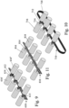
- FIGS 9 to 11 show perspective views of different conveyors that can serve as the drive members 120, 220 and 320 in the embodiments shown in Figures 3-8 .
- the drive member is a chain 610.
- saddles 612 are secured to the chain.
- Each saddle 612 is secured to the chain by two pins 613 that serve as pivots between the individual links of the chain 610.
- Each saddle 612 supports an axle 614 that carries, in the non-limiting exemplary illustration, two mandrels 616, 618 located one on each side of the chain 610.
- Figure 10 is generally similar to Figure 9 save that a belt 710, which can be plain or toothed, is used in place of a chain, and saddles 712 are integrally formed with the belt 710 or are bonded to it. Once again, each saddle 712 supports an axle 714 that carries two mandrels 716, 718 located one on each side of the belt 710.
- the drive member is once again a chain 810 but no saddle is used to mount each pair of mandrels 816, 818. Instead the axle 814 of each pair of mandrels is part of a pivot pin connecting adjacent links of the chain. One or two such pins may be employed to secure each axle.
- inventions shown in Figures 9, 10 and 11 are designed for printing on cylindrical objects of circular section.
- shape of the mandrel may be adapted so as to better fit the shape of the object to be mounted thereon.
- an ITM suitable for transferring ink images to the outer surfaces of generally cylindrical objects can be formed of one or more elongated blanket strips.
- the ends of the strip can be attached to one another by soldering, gluing, taping ( e.g ., using silicone adhesive strips, Kapton ® tape, RTV liquid adhesives or PTFE thermoplastic adhesives with a connective strip overlapping both edges of the strip), or any other method commonly known. Any method of joining the ends of the blanket strip to form a transfer belt may cause a discontinuity, referred to herein as a seam.
- the seam can be of different types.
- the edges may overlap one another or a patch may be applied to overlie the two ends.
- the seam may be subsequently processed, such as by grinding, to reduce its thickness to obtain an ITM having substantially the same thickness along the entire loop.
- the printing process can be adapted to avoid applying an ink image in an area of the ITM including a seam.
- the feeding of the objects being printed upon needs to be accordingly discontinued, so that objects are transported through the impression station only synchronously with actual presence of ink images on the image bearing surface.
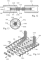
- Figure 12 shows a section through the drive member 810 of Figure 11 , the section plane passing through the axis of the shaft 814.
- the shaft 814 which acts as a pivot between two links of the chain 810, projects symmetrically from each side of the chain.
- a hub 1214 is secured to the shaft 814.
- the end of the hub 1214 remote from the chain 810 incorporates a magnet 1216.
- Each mandrel is hollow and, as shown in the section of Figure 13 in respect of the mandrel 816, comprises an inner tube 816a connected to an outer cylinder 816b by radial webs or posts 816c.
- a space 816d between the inner tube 816a and the outer cylinder 816b serves as an air duct.
- the inner tube 816a is mounted for rotation about the shaft 814 by means of bearings 1218a, 1218b located one at each end of the inner tube 816a.
- Each mandrel 816, 818 is fitted to the shaft 814 so that it can be pulled on and off simply and yet retained securely when in position. Retention of each mandrel is achieved by the magnet 1216 and/or by a spring-biased detent 1220 located in the shaft 814 adjacent the bearing 1218a proximal to the drive member.
- Such mounting allows the mandrels 816, 818 to be easily and quickly replaced by smaller ones when printing on smaller objects and enables individual mandrels to be removed when they synchronize with a no-print region of the ITM.
- FIG. 14 and 15 A loading station is shown in Figures 14 and 15 at which objects 106 are placed from two stacks 1430, 1432 onto the mandrels 816, 818 shown by way of non-limiting examples in Figures 11 to 13 .
- a drive member 810 in the form of a chain drives the pairs of mandrels 816, 818 in the direction of the arrow 1422, the drive member being shown in Figure 15 but not in Figure 14 .
- Two further chain conveyors 1428 are located one on each side of the drive member 810 and run alongside it and at the same speed.
- the conveyors 1428 carry cradles 1416, 1418 for supporting objects with their axes aligned with the axes of the mandrels 816, 818.
- the shape of the cradles can be varied for each diameter and/or the conveyer can be lowered or heightened with respect to the drive member, ensuring that the longitudinal axis of the object on the cradle is aligned to be co-axial with the shaft of the mandrel.
- the path followed by the cradles 1416, 1418 is adjustable, such as by moving the sprockets driving the chain conveyors 1428, or by repositioning a guide along which the links of the chain conveyor 1428 slide. In this way, as the mandrels move through the loading station, a cradle travels alongside each mandrel at the same speed.
- an interposer 1510 shown in Figure 15 . If a mandrel is present on the drive member 810, then an object can drop into the cradle aligned with it, whereas if the mandrel has been removed, for example because it synchronizes with a no-print region, then the interposer 1510 prevents an object from dropping out of the stack onto the passing cradle.
- the interposer can 1510 be constructed in a variety of ways. In its simplest form, it may operate purely mechanically and take the form of a pivotable shaft having at one end a finger obstructing the decent of objects 106 from a stack and at the other end a sensing lever that rides on the mandrels. If a mandrel is present, then the sensing lever rotates the shaft to displace the finger lying in the path of the falling objects, whereas when no mandrel is present, the finger at the opposite end of the shaft prevents loading of an object onto the associated cradle.
- the interposer may operate electrically and take the form of a solenoid operating a gate at the bottom of each stack.
- the solenoid may receive signals to close the gate either upon detection of the absence of a mandrel by an associated electrical sensor.
- a pre-programmed digital processor which controls the application of ink images to the ITM may send signals to the interposer 1510 to prevent loading of object at positions that synchronize with no-print regions of the ITM.
- the transfer of objects from the cradles 1416, 1418, to the mandrels 816, 818 can be performed mechanically, most simply by a stationary ramp acting on the closed end of the objects 106. However, in some embodiments shown in Figures 16 and 17 , the transfer is performed pneumatically.
- air jets represented by arrows 1610 emitted by air knives (not shown) push the objects towards the mandrels 816, 818.
- a suction pump connected to a passage 1612 communicating with the conduits 816d within the hollow mandrels 816, 818, draws air in the direction of the arrows 1614 and sucks the objects onto the mandrels.
- Chamfered ends 816e of the outer cylinders 816b of the mandrels allow slight misalignment between the axes of the objects and the mandrels to be tolerated. Suction, or mechanical constraint, may continue to be applied to the objects, ensuring that they remain well seated on the mandrels until completion of printing.
- the mandrels 816, 818 are once again aligned with adjacent cradles that are advanced at the same speed and positive pressure represented by the arrows 1714 is applied via a passage 1712 to blow the objects off the mandrels and onto the cradles.
- FIG 18 this shows a complete section of a production line in which printing takes place on four columns of objects, arranged in two pairs of columns, the mandrel of each pair of columns sharing a common drive member, as shown in Figure 11 .
- Printing can be performed by a system 1810 which is described in detail in WO 2013/132418 .
- An ITM 1812 having a hydrophobic outer release surface circulates clockwise, as represented by an arrow 1814.
- the ITM 1812 first passes beneath an imaging station 1816 having a plurality of print bars 1818 that can deposit aqueous inks of different colors on the ITM 1812.
- the ITM 1812 then passes through two drying stations 1820a and 1820b that evaporate the aqueous carrier and leave behind a polymeric tacky ink image.
- an impression station 1822 presently illustrated by the type shown in Figure 7
- the ink image is transferred onto the generally cylindrical objects and the ITM 1812 then passes through a cleaning and/or conditioning station 1824 before it returns to the imaging station 1816 to commence a fresh cycle.
- the objects on which printing is to take place are supplied in the illustrated embodiment from two pairs of stacks, 1830 and 1832, to two loading stations designated 1834a and 1834b, each of which is as previously described by reference to Figures 14 and 15 . As there is not sufficient space for two loading stations to be located side by side, they are arranged in different horizontal planes.
- the objects are next advanced in rows of four first through an optional pretreatment station 1836a where they may, for example, be subjected to a flame, a corona or a plasma.
- a primer can be applied to the objects at a priming station 1838 and the primer, if applied, is dried in a drying station 1840, after which the objects may be further treated at pretreatment station 1836b before entering the impression station 1822.
- an ink image After an ink image has been impressed on the objects, they may optionally pass again through a pre-treatment station 1842, where the objects may be subjected to a flame, a corona or plasma to prepare them for a varnish coating that can be applied at a varnishing station 1844.
- the varnish if applied, has been dried or otherwise cured such as, for example, by UV exposure or e-beam radiation in drying/curing station 1846, the paths of the two drive members carrying the mandrels once again diverge to take each drive member through a respective one of two unloading stations 1848a and 1848b at which the objects are sent on to further processing stations of the production line.
- the objects In a production line for beverage cans, the objects may, for example, be internally coated or subsequently have their shape modified, and they may be filled with a beverage before a cap is secured to them to seal their contents.
- Drying station 1840 and 1846 may also serve as heating stations for the mandrels and the objects to ensure that the surface of the objects enter the impression station at an elevated temperature which, in some embodiments, may be desirable to help ensure complete image transfer.
- Such pre-heating of the mandrels may also be accomplished by the addition of heaters or heating ovens at any location in the mandrel path, as, in some embodiments, the heat capacity of the mandrels enables them to heat the objects and maintain their elevated temperature even when not continuously exposed to external heat sources. Though any temperature above room temperature may be desirable, preferred mandrel temperatures may be between 30°C and 100°C.
- all the stacks 1830, 1832 have interposers, as previously described, to provide skip feeding mechanisms that prevent loading of objects onto mandrels that have been removed, because they would arrive at the impression station 1822 at times coinciding with no-print regions of the ITM 1812.
- Regions of the ITM 1812 may be designated as no-print regions, not only because they straddle a seam of the ITM 1812 but also if the ITM has a local defect, or for any other reason.
- the speed of the ITM 1812 needs to be twice that of drive members of the mandrels. However, minor adjustments may be made to the speed of the ITM 1812 or of the drive members to ensure correct synchronization with the objects. Such adjustments to the synchronization are necessary as each of the ITM 1812 and the drive members has a degree of elasticity which requires slight periodic compensation to ensure that the ink images and the objects meet one another in register at the impression station when transfer is effected.
- the length of the ITM 1812 it is necessary for the length of the ITM 1812 to be a whole number multiple of the pitch between the objects. Since the ITM 1812 is somewhat elastic, tensioning of the ITM 1812 can be used to make minor adjustments to its length. It is for this reason that the ITM 1812 in Figure 18 also passes over a tensioning roller 1850.
- the entire object handling system including loading stations 1834a and 1834b, pretreatment stations 1836a, 1836b and 1842, drying/curing stations 1840 and 1846, unloading stations 1848a and 1848b, as well as the impression platen and the chain/belt drive member transmission system, be constructed in such a manner that it can slide out from under the printing system and ITM, in a direction orthogonal to the printing process direction, as a single unit for access and maintenance. This can be readily facilitated by floor-supported rollers or tracks.
- the objects are directly urged against the ITM at the nip by means of a stationary impression platen in contact with the objects on their opposite side to that in contact with the ITM.
- a stationary impression platen in contact with the objects on their opposite side to that in contact with the ITM.
- a force via the transport mechanism
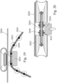
- Figure 19 is a variant of the embodiment of Figure 5 and Figure 20 is a cross section of a detail of Figure 19 , corresponding to the section shown in Figure 12 .
- bearings 2050 which are shown as ball bearings but may alternatively be friction bearings, are fitted (as shown in Figure 20 ) around the hubs 2014 surrounding the shafts on which the mandrels 2022 are mounted.
- the stationary platen 2024 in this embodiment applies a force to the outer races of the bearings 2050, which force is duly transmitted via the mandrels 2022 to the surface of the objects in contact with the ITM 2030.
- a printing apparatus as herein disclosed may further comprise inter alia a conditioning station and/or a cleaning station to respectively treat ( e.g ., by physical or chemical means) and/or clean the intermediate transfer member (such as illustrated by 36 in Figure 2 ), a drying station to evaporate liquid carrier out of the ink image (such as illustrated by 34 in Figure 2 ), a cleaning station to remove debris from the ITM (not show) and a cooling or a heating station to modify the temperature of the intermediate transfer member along its path ( e.g., to facilitate ink image deposition or transfer; not shown).
- a conditioning station and/or a cleaning station to respectively treat ( e.g ., by physical or chemical means) and/or clean the intermediate transfer member (such as illustrated by 36 in Figure 2 ), a drying station to evaporate liquid carrier out of the ink image (such as illustrated by 34 in Figure 2 ), a cleaning station to remove debris from the ITM (not show) and a cooling or a heating station to modify the temperature of the intermediate transfer member along its path (
- the printing system may additionally, or alternatively, comprise stations wherein the object is processed.
- the printing system may include a forming station where the object can be formed into a generally cylindrical object optionally including a lid at one end, a shaping station where surfaces of the object can be embossed or otherwise modified to include a functional or decorative pattern; a washing station where the object can be degreased or etched ( e.g., ahead of printing), a drying station where a wet object can be dried (ahead of and/or following printing), a priming station where a priming composition or treatment (e.g., corona) can be applied to the outer surface of the object prior to printing ( e.g., to further the adherence of the ink image to the object), a heating or a cooling to modify the object temperature along its path, a curing station (e.g., to cure an ink image transferred to the object), a coating station (e.g., to coat the transferred ink image with a protective or
- the printing systems of the present disclosure can be connected in-line with a downstream filling system, wherein the printed objects can be filled with their intended content and lids thereafter attached ( e.g., seamed by welding) to the filled bodies to seal the contents. All such stations known in the fields of printing and packaging need not be considered in detail in the present context.
- US 5,893,016 describes an apparatus for printing images on generally cylindrical objects such as cans, including an image bearing surface having an image thereon and having an impression guide which is generally parallel to and spaced from the image bearing surface, which guide supports the cylindrical objects in rolling contact with the image bearing surface, whereby images are transferred from the image bearing surface to surfaces of the cylindrical objects in contact therewith.
- the objects are not supported on mandrels and the apparatus is not therefore well suited to printing on cans before they are filled and sealed.
- the articles are not advanced by a drive member through the printing station, relying instead first on gravity then on friction with the image bearing surface, and there is nothing to prevent the articles from skewing, prior to or during their passage through the printing station.
- Printing sub-systems suitable for the apparatuses according to the present teachings are known to the skilled person and need not be detailed herein. Exemplary sub-systems which may be used, in some embodiments, are further detailed in WO 2017/208145 and WO 2017/208146 , wherein, as opposed to the present invention, the objects are mounted on mandrels attached to a rigid support, the ink images being transferred in absence of an impression platen.
- Consumables suitable for printing methods and apparatuses include, in addition to the generally cylindrical objects being printed on, at least one of a) ink compositions, b) intermediate transfer members (e.g., continuous belts with or without a seam), and optionally c) conditioning liquids I (e.g., for pre-treating the transfer members ahead of ink application), d) cleaning or washing liquids (e.g., for removing ink residuals from transfer members or degreasing the objects), e) priming liquids ( e.g., for pre-coating the objects prior to printing), f) coating liquids ( e.g., for applying an overcoat covering the ink image on the printed object), g) lining liquids ( e.g., for applying a coat to the interior of the object); and h) like compositions readily appreciated by a person skilled in the art of printing.
- conditioning liquids I e.g., for pre-treating the transfer members ahead of ink application
- cleaning or washing liquids e
- Such consumables are selected and adapted to any desired particular configuration and operation of the printing method and apparatus.
- the consumables are compatible with one another. For instance, if, during the printing process, the image bearing surface of the ITM is to be exposed to elevated temperature, it should be heat resistant at least to the applied temperature; if the transfer member is a tensioned belt, it should have mechanical resistance at least to the applied tension; if the transfer member is displaced, it should include, on the side opposite the surface upon which ink is deposited, a layer providing suitable friction or lack thereof with underneath guiding systems; and any such consideration readily appreciated by a person skilled in printing allowing use of the consumable under the operating conditions.
- the ink compositions need first be compatible with the intermediate transfer member and/or with a conditioning liquid (if present). They also need to be adapted to the surface of the object the inks are printed on, and/or with a priming compound and/or with a coating compound (if any pre- or post- applied to the object).
- a material or a chemical composition is compatible with another if it does not prevent its activity or does not reduce it to an extent that would significantly affect the intended purpose.
- the ink compositions would not be compatible if, among other things, swelling the imaging surface of the ITM or otherwise distorting its characteristics, if being unable to at least partially transfer from the image bearing outer surface and/or attach to the surface of the object, whether or not pre-coated, unable to attach an overcoat, resisting cleaning of the printing system, and any like undesired effect.
- this principle of chemical compatibility of any consumable used herein with any other consumable should preferably guide the selection of all materials necessary for the compositions to be used in a printing system as disclosed herein.
- Consumables suitable for printing methods and apparatuses according to the present teachings are known to the skilled person and need not be detailed herein. Exemplary consumables which may be used, in some embodiments, are further detailed in WO 2013/132418 and WO 2017/208152 .
- Ink compositions suitable for printing methods and apparatuses according to the present teachings are known to the skilled person and need not be detailed herein. Exemplary ink compositions which may be used, in some embodiments, are further detailed in WO 2013/132339 , WO 2015/036812 and WO 2015/036865 .
- Conditioning liquids suitable for printing methods and apparatuses according to the present teachings are known to the skilled person and need not be detailed herein. Exemplary conditioning liquids which may be used, in some embodiments, are further detailed in WO 2013/132339 , WO 2015/036864 , WO 2015/036960 and WO 2017/208246 .
Landscapes
- Engineering & Computer Science (AREA)
- Manufacturing & Machinery (AREA)
- Mechanical Engineering (AREA)
- Health & Medical Sciences (AREA)
- General Health & Medical Sciences (AREA)
- Toxicology (AREA)
- Printing Methods (AREA)
- Handling Of Sheets (AREA)
- Ink Jet (AREA)
Applications Claiming Priority (3)
| Application Number | Priority Date | Filing Date | Title |
|---|---|---|---|
| GB1814882.5A GB2577086B (en) | 2018-09-13 | 2018-09-13 | Printing on cylindrical objects |
| GB1907890.6A GB2577151B (en) | 2018-09-13 | 2019-06-03 | Method and apparatus for printing on cylindrical objects |
| PCT/IB2019/057474 WO2020053709A1 (en) | 2018-09-13 | 2019-09-05 | Method and apparatus for printing on cylindrical objects |
Publications (2)
| Publication Number | Publication Date |
|---|---|
| EP3849811A1 EP3849811A1 (en) | 2021-07-21 |
| EP3849811B1 true EP3849811B1 (en) | 2024-12-25 |
Family
ID=64013144
Family Applications (1)
| Application Number | Title | Priority Date | Filing Date |
|---|---|---|---|
| EP19769244.5A Active EP3849811B1 (en) | 2018-09-13 | 2019-09-05 | Method and apparatus for printing on generally cylindrical objects |
Country Status (9)
| Country | Link |
|---|---|
| US (3) | US11541652B2 (https=) |
| EP (1) | EP3849811B1 (https=) |
| JP (1) | JP7344592B2 (https=) |
| CN (1) | CN112689564B (https=) |
| AU (1) | AU2019337479B2 (https=) |
| CA (1) | CA3112641A1 (https=) |
| GB (2) | GB2577086B (https=) |
| IL (1) | IL281432B2 (https=) |
| WO (1) | WO2020053709A1 (https=) |
Families Citing this family (9)
| Publication number | Priority date | Publication date | Assignee | Title |
|---|---|---|---|---|
| AU2018337813B2 (en) * | 2017-09-19 | 2021-05-13 | Ball Corporation | Container decoration apparatus and method |
| GB2577086B (en) | 2018-09-13 | 2022-02-23 | Landa Labs 2012 Ltd | Printing on cylindrical objects |
| JP7240165B2 (ja) * | 2018-12-18 | 2023-03-15 | アルテミラ株式会社 | 印刷システム |
| CN113085399B (zh) * | 2021-05-20 | 2022-04-19 | 深圳市富彩包装有限公司 | 一种彩色包装印刷方法 |
| EP4137327A1 (de) | 2021-08-18 | 2023-02-22 | HINTERKOPF GmbH | Bedruckungsverfahren für einen metallbehälter und vorrichtung zum bedrucken eines metallbehälters |
| JP2024003990A (ja) * | 2022-06-28 | 2024-01-16 | 富士フイルムビジネスイノベーション株式会社 | 画像形成装置 |
| CN117103851B (zh) * | 2023-10-09 | 2024-01-30 | 河北新东印刷有限公司 | 一种全自动高效不干胶印刷机及其印刷方法 |
| WO2025239903A1 (en) * | 2024-05-17 | 2025-11-20 | Hewlett-Packard Development Company, L.P. | Printing upon curved surfaces |
| JP2026022093A (ja) | 2024-07-30 | 2026-02-12 | 富士フイルムビジネスイノベーション株式会社 | 画像形成装置 |
Citations (1)
| Publication number | Priority date | Publication date | Assignee | Title |
|---|---|---|---|---|
| WO2019060394A1 (en) * | 2017-09-19 | 2019-03-28 | Ball Corporation | METHOD AND APPARATUS FOR CONTAINER DECORATION |
Family Cites Families (34)
| Publication number | Priority date | Publication date | Assignee | Title |
|---|---|---|---|---|
| US2799220A (en) * | 1955-02-18 | 1957-07-16 | Trapow & Co Ltd D | Printing machines |
| US3279360A (en) * | 1965-09-13 | 1966-10-18 | Miehle Goss Dexter Inc | Machine for printing on cylindrical articles |
| US3565034A (en) * | 1968-10-25 | 1971-02-23 | Mandrel Industries | Processing apparatus for objects |
| US3766851A (en) * | 1971-11-15 | 1973-10-23 | Sun Chemical Corp | Continuous can printer and handling apparatus |
| US3915288A (en) * | 1972-04-07 | 1975-10-28 | Continental Can Co | Conveyor apparatus for high speed can printing machine |
| US4337719A (en) * | 1981-04-16 | 1982-07-06 | Van Dam Machine Corporation Of America | Mandrel support means for container decorating apparatus |
| NL192329C (nl) * | 1986-07-04 | 1997-06-04 | Thomassen & Drijver | Inrichting voor het bedrukken van bekers of bussen. |
| FR2670759B1 (fr) * | 1990-12-19 | 1993-04-09 | Engineering Machine Cy Ltd | Dispositif pour equiper simultanement plusieurs mandrins avec des pieces cylindriques. |
| IL113552A (en) * | 1995-04-30 | 2005-09-25 | Hewlett Packard Indigo Bv | Apparatus and method for centerless printing of images particularly on cylindrical objects |
| US6367380B1 (en) * | 1998-02-02 | 2002-04-09 | Sequa Can Machinery, Inc. | Inking system with a belt and differential roller speeds |
| US6651552B1 (en) * | 2002-07-22 | 2003-11-25 | Sequa Can Machinery, Inc. | Automated can decorating apparatus having mechanical mandrel trip |
| FR2905630B1 (fr) | 2006-09-12 | 2010-01-22 | Impika | Dispositif d'impression par transfert sur un support d'impression cylindrique |
| KR101153104B1 (ko) * | 2007-08-03 | 2012-06-04 | 케이에이치에스 게엠베하 | 용기에 인쇄를 하기 위한 장치 및 방법 |
| US9475276B2 (en) * | 2011-04-27 | 2016-10-25 | Stolle Machinery Company, Llc | Can decorator machine, ink station assembly therefor, and can decorating method employing same |
| DE102011083220A1 (de) * | 2011-09-22 | 2013-03-28 | Krones Aktiengesellschaft | Behälterbedruckungsanlage |
| WO2013132438A2 (en) | 2012-03-05 | 2013-09-12 | Landa Corporation Ltd. | Protonatable intermediate transfer members for use with indirect printing systems |
| AU2013229050A1 (en) | 2012-03-05 | 2014-09-11 | Landa Corporation Ltd. | Inkjet ink formulations |
| EP2822776B1 (en) | 2012-03-05 | 2018-08-01 | Landa Corporation Ltd. | Transfer printing method |
| WO2013132418A2 (en) | 2012-03-05 | 2013-09-12 | Landa Corporation Limited | Digital printing process |
| WO2013132432A1 (en) | 2012-03-05 | 2013-09-12 | Landa Corporation Ltd. | Intermediate transfer members for use with indirect printing systems |
| CN203557820U (zh) | 2013-02-20 | 2014-04-23 | 皇冠包装技术公司 | 容器罐装饰机设备 |
| WO2015036864A1 (en) | 2013-09-11 | 2015-03-19 | Landa Corporation Ltd. | Treatment of release layer |
| US9782993B2 (en) | 2013-09-11 | 2017-10-10 | Landa Corporation Ltd. | Release layer treatment formulations |
| GB201401173D0 (en) | 2013-09-11 | 2014-03-12 | Landa Corp Ltd | Ink formulations and film constructions thereof |
| WO2015036812A1 (en) | 2013-09-12 | 2015-03-19 | Landa Corporation Ltd. | Ink formulations and film constructions thereof |
| DE102015201341A1 (de) * | 2015-01-27 | 2016-07-28 | Tampoprint Ag | Vorrichtung zum indirekten Bedrucken eines zylindrischen Teils |
| US10486368B2 (en) | 2015-12-28 | 2019-11-26 | The Procter & Gamble Company | Method for transferring material with adhesive onto articles with a difference in degree of curing between the material and adhesive |
| EP3463897B1 (en) | 2016-05-30 | 2021-01-13 | Landa Corporation Ltd. | Digital printing process and system |
| IL262529B2 (en) | 2016-05-30 | 2023-06-01 | Landa Labs 2012 Ltd | A method for creating a multi-layered product |
| WO2017208146A1 (en) | 2016-05-30 | 2017-12-07 | Landa Labs (2012) Ltd | Apparatus for printing on conical objects |
| GB201609463D0 (en) | 2016-05-30 | 2016-07-13 | Landa Labs 2012 Ltd | Method of manufacturing a multi-layer article |
| CN112428691B (zh) | 2016-05-30 | 2022-09-27 | 兰达公司 | 数字印刷方法和系统 |
| CN114148098B (zh) | 2016-05-30 | 2025-03-07 | 兰达公司 | 数字印刷方法 |
| GB2577086B (en) * | 2018-09-13 | 2022-02-23 | Landa Labs 2012 Ltd | Printing on cylindrical objects |
-
2018
- 2018-09-13 GB GB1814882.5A patent/GB2577086B/en not_active Withdrawn - After Issue
-
2019
- 2019-06-03 GB GB1907890.6A patent/GB2577151B/en not_active Withdrawn - After Issue
- 2019-09-05 IL IL281432A patent/IL281432B2/en unknown
- 2019-09-05 EP EP19769244.5A patent/EP3849811B1/en active Active
- 2019-09-05 JP JP2021514111A patent/JP7344592B2/ja active Active
- 2019-09-05 AU AU2019337479A patent/AU2019337479B2/en active Active
- 2019-09-05 CN CN201980060043.XA patent/CN112689564B/zh active Active
- 2019-09-05 CA CA3112641A patent/CA3112641A1/en active Pending
- 2019-09-05 WO PCT/IB2019/057474 patent/WO2020053709A1/en not_active Ceased
-
2021
- 2021-03-12 US US17/199,487 patent/US11541652B2/en active Active
-
2022
- 2022-11-08 US US18/053,428 patent/US11926144B2/en active Active
-
2024
- 2024-01-28 US US18/424,809 patent/US12434470B2/en active Active
Patent Citations (1)
| Publication number | Priority date | Publication date | Assignee | Title |
|---|---|---|---|---|
| WO2019060394A1 (en) * | 2017-09-19 | 2019-03-28 | Ball Corporation | METHOD AND APPARATUS FOR CONTAINER DECORATION |
Also Published As
| Publication number | Publication date |
|---|---|
| CN112689564B (zh) | 2022-09-30 |
| GB201907890D0 (en) | 2019-07-17 |
| US11926144B2 (en) | 2024-03-12 |
| IL281432B1 (en) | 2025-04-01 |
| EP3849811A1 (en) | 2021-07-21 |
| WO2020053709A1 (en) | 2020-03-19 |
| US20230065407A1 (en) | 2023-03-02 |
| US12434470B2 (en) | 2025-10-07 |
| GB201814882D0 (en) | 2018-10-31 |
| GB2577086A (en) | 2020-03-18 |
| JP2022500284A (ja) | 2022-01-04 |
| US20210197547A1 (en) | 2021-07-01 |
| GB2577086B (en) | 2022-02-23 |
| AU2019337479B2 (en) | 2024-07-25 |
| US11541652B2 (en) | 2023-01-03 |
| AU2019337479A1 (en) | 2021-04-08 |
| JP7344592B2 (ja) | 2023-09-14 |
| IL281432B2 (en) | 2025-08-01 |
| GB2577151A (en) | 2020-03-18 |
| WO2020053709A8 (en) | 2020-05-07 |
| CA3112641A1 (en) | 2020-03-19 |
| GB2577151B (en) | 2022-02-23 |
| IL281432A (en) | 2021-04-29 |
| CN112689564A (zh) | 2021-04-20 |
| US20240165944A1 (en) | 2024-05-23 |
Similar Documents
| Publication | Publication Date | Title |
|---|---|---|
| US12434470B2 (en) | Apparatus for printing on cylindrical objects having device to prevent loading of objects onto mandrels | |
| RU2433049C1 (ru) | Устройство для нанесения печатного изображения на наружной поверхности бутылок или сосудов подобного рода | |
| JP6923221B2 (ja) | 3次元物体に印刷する装置 | |
| US5339731A (en) | Method and apparatus for printing multicolored container body blanks in a single pass | |
| CN106536201B (zh) | 用于印刷空心体的设备 | |
| US20180178551A1 (en) | Printing press assembly having a plurality of processing stations for processing sheets and method for operating the printing press assembly | |
| RU2750565C1 (ru) | Машина для нанесения изображений на контейнеры и способ | |
| CN106536202B (zh) | 具有多个分别用于印刷空心体的印刷装置的设备 | |
| US20190022998A1 (en) | Device for printing hollow bodies, and method for operating said device | |
| US3279360A (en) | Machine for printing on cylindrical articles | |
| US6907823B2 (en) | Flexographic printing on containers | |
| AU2019261794B2 (en) | Apparatus and method for printing on three-dimensional objects | |
| WO2020004003A1 (ja) | 印刷装置 | |
| JP2019206127A (ja) | 印刷装置および印刷方法 |
Legal Events
| Date | Code | Title | Description |
|---|---|---|---|
| STAA | Information on the status of an ep patent application or granted ep patent |
Free format text: STATUS: UNKNOWN |
|
| STAA | Information on the status of an ep patent application or granted ep patent |
Free format text: STATUS: THE INTERNATIONAL PUBLICATION HAS BEEN MADE |
|
| PUAI | Public reference made under article 153(3) epc to a published international application that has entered the european phase |
Free format text: ORIGINAL CODE: 0009012 |
|
| STAA | Information on the status of an ep patent application or granted ep patent |
Free format text: STATUS: REQUEST FOR EXAMINATION WAS MADE |
|
| 17P | Request for examination filed |
Effective date: 20210310 |
|
| AK | Designated contracting states |
Kind code of ref document: A1 Designated state(s): AL AT BE BG CH CY CZ DE DK EE ES FI FR GB GR HR HU IE IS IT LI LT LU LV MC MK MT NL NO PL PT RO RS SE SI SK SM TR |
|
| DAV | Request for validation of the european patent (deleted) | ||
| DAX | Request for extension of the european patent (deleted) | ||
| STAA | Information on the status of an ep patent application or granted ep patent |
Free format text: STATUS: EXAMINATION IS IN PROGRESS |
|
| 17Q | First examination report despatched |
Effective date: 20240124 |
|
| GRAP | Despatch of communication of intention to grant a patent |
Free format text: ORIGINAL CODE: EPIDOSNIGR1 |
|
| STAA | Information on the status of an ep patent application or granted ep patent |
Free format text: STATUS: GRANT OF PATENT IS INTENDED |
|
| INTG | Intention to grant announced |
Effective date: 20240925 |
|
| GRAS | Grant fee paid |
Free format text: ORIGINAL CODE: EPIDOSNIGR3 |
|
| GRAA | (expected) grant |
Free format text: ORIGINAL CODE: 0009210 |
|
| STAA | Information on the status of an ep patent application or granted ep patent |
Free format text: STATUS: THE PATENT HAS BEEN GRANTED |
|
| P01 | Opt-out of the competence of the unified patent court (upc) registered |
Free format text: CASE NUMBER: APP_60207/2024 Effective date: 20241107 |
|
| AK | Designated contracting states |
Kind code of ref document: B1 Designated state(s): AL AT BE BG CH CY CZ DE DK EE ES FI FR GB GR HR HU IE IS IT LI LT LU LV MC MK MT NL NO PL PT RO RS SE SI SK SM TR |
|
| REG | Reference to a national code |
Ref country code: GB Ref legal event code: FG4D |
|
| REG | Reference to a national code |
Ref country code: CH Ref legal event code: EP |
|
| REG | Reference to a national code |
Ref country code: DE Ref legal event code: R096 Ref document number: 602019063974 Country of ref document: DE |
|
| REG | Reference to a national code |
Ref country code: IE Ref legal event code: FG4D |
|
| REG | Reference to a national code |
Ref country code: NL Ref legal event code: FP |
|
| REG | Reference to a national code |
Ref country code: LT Ref legal event code: MG9D |
|
| PG25 | Lapsed in a contracting state [announced via postgrant information from national office to epo] |
Ref country code: HR Free format text: LAPSE BECAUSE OF FAILURE TO SUBMIT A TRANSLATION OF THE DESCRIPTION OR TO PAY THE FEE WITHIN THE PRESCRIBED TIME-LIMIT Effective date: 20241225 |
|
| PG25 | Lapsed in a contracting state [announced via postgrant information from national office to epo] |
Ref country code: FI Free format text: LAPSE BECAUSE OF FAILURE TO SUBMIT A TRANSLATION OF THE DESCRIPTION OR TO PAY THE FEE WITHIN THE PRESCRIBED TIME-LIMIT Effective date: 20241225 |
|
| PG25 | Lapsed in a contracting state [announced via postgrant information from national office to epo] |
Ref country code: BG Free format text: LAPSE BECAUSE OF FAILURE TO SUBMIT A TRANSLATION OF THE DESCRIPTION OR TO PAY THE FEE WITHIN THE PRESCRIBED TIME-LIMIT Effective date: 20241225 |
|
| PG25 | Lapsed in a contracting state [announced via postgrant information from national office to epo] |
Ref country code: NO Free format text: LAPSE BECAUSE OF FAILURE TO SUBMIT A TRANSLATION OF THE DESCRIPTION OR TO PAY THE FEE WITHIN THE PRESCRIBED TIME-LIMIT Effective date: 20250325 |
|
| PG25 | Lapsed in a contracting state [announced via postgrant information from national office to epo] |
Ref country code: LV Free format text: LAPSE BECAUSE OF FAILURE TO SUBMIT A TRANSLATION OF THE DESCRIPTION OR TO PAY THE FEE WITHIN THE PRESCRIBED TIME-LIMIT Effective date: 20241225 Ref country code: GR Free format text: LAPSE BECAUSE OF FAILURE TO SUBMIT A TRANSLATION OF THE DESCRIPTION OR TO PAY THE FEE WITHIN THE PRESCRIBED TIME-LIMIT Effective date: 20250326 |
|
| PG25 | Lapsed in a contracting state [announced via postgrant information from national office to epo] |
Ref country code: RS Free format text: LAPSE BECAUSE OF FAILURE TO SUBMIT A TRANSLATION OF THE DESCRIPTION OR TO PAY THE FEE WITHIN THE PRESCRIBED TIME-LIMIT Effective date: 20250325 |
|
| REG | Reference to a national code |
Ref country code: AT Ref legal event code: MK05 Ref document number: 1753851 Country of ref document: AT Kind code of ref document: T Effective date: 20241225 |
|
| PG25 | Lapsed in a contracting state [announced via postgrant information from national office to epo] |
Ref country code: SM Free format text: LAPSE BECAUSE OF FAILURE TO SUBMIT A TRANSLATION OF THE DESCRIPTION OR TO PAY THE FEE WITHIN THE PRESCRIBED TIME-LIMIT Effective date: 20241225 |
|
| PG25 | Lapsed in a contracting state [announced via postgrant information from national office to epo] |
Ref country code: PL Free format text: LAPSE BECAUSE OF FAILURE TO SUBMIT A TRANSLATION OF THE DESCRIPTION OR TO PAY THE FEE WITHIN THE PRESCRIBED TIME-LIMIT Effective date: 20241225 |
|
| PG25 | Lapsed in a contracting state [announced via postgrant information from national office to epo] |
Ref country code: ES Free format text: LAPSE BECAUSE OF FAILURE TO SUBMIT A TRANSLATION OF THE DESCRIPTION OR TO PAY THE FEE WITHIN THE PRESCRIBED TIME-LIMIT Effective date: 20241225 |
|
| PG25 | Lapsed in a contracting state [announced via postgrant information from national office to epo] |
Ref country code: IS Free format text: LAPSE BECAUSE OF FAILURE TO SUBMIT A TRANSLATION OF THE DESCRIPTION OR TO PAY THE FEE WITHIN THE PRESCRIBED TIME-LIMIT Effective date: 20250425 |
|
| PG25 | Lapsed in a contracting state [announced via postgrant information from national office to epo] |
Ref country code: PT Free format text: LAPSE BECAUSE OF FAILURE TO SUBMIT A TRANSLATION OF THE DESCRIPTION OR TO PAY THE FEE WITHIN THE PRESCRIBED TIME-LIMIT Effective date: 20250428 |
|
| PG25 | Lapsed in a contracting state [announced via postgrant information from national office to epo] |
Ref country code: EE Free format text: LAPSE BECAUSE OF FAILURE TO SUBMIT A TRANSLATION OF THE DESCRIPTION OR TO PAY THE FEE WITHIN THE PRESCRIBED TIME-LIMIT Effective date: 20241225 |
|
| PG25 | Lapsed in a contracting state [announced via postgrant information from national office to epo] |
Ref country code: AT Free format text: LAPSE BECAUSE OF FAILURE TO SUBMIT A TRANSLATION OF THE DESCRIPTION OR TO PAY THE FEE WITHIN THE PRESCRIBED TIME-LIMIT Effective date: 20241225 Ref country code: RO Free format text: LAPSE BECAUSE OF FAILURE TO SUBMIT A TRANSLATION OF THE DESCRIPTION OR TO PAY THE FEE WITHIN THE PRESCRIBED TIME-LIMIT Effective date: 20241225 |
|
| PG25 | Lapsed in a contracting state [announced via postgrant information from national office to epo] |
Ref country code: SK Free format text: LAPSE BECAUSE OF FAILURE TO SUBMIT A TRANSLATION OF THE DESCRIPTION OR TO PAY THE FEE WITHIN THE PRESCRIBED TIME-LIMIT Effective date: 20241225 |
|
| PG25 | Lapsed in a contracting state [announced via postgrant information from national office to epo] |
Ref country code: CZ Free format text: LAPSE BECAUSE OF FAILURE TO SUBMIT A TRANSLATION OF THE DESCRIPTION OR TO PAY THE FEE WITHIN THE PRESCRIBED TIME-LIMIT Effective date: 20241225 |
|
| PG25 | Lapsed in a contracting state [announced via postgrant information from national office to epo] |
Ref country code: IT Free format text: LAPSE BECAUSE OF FAILURE TO SUBMIT A TRANSLATION OF THE DESCRIPTION OR TO PAY THE FEE WITHIN THE PRESCRIBED TIME-LIMIT Effective date: 20241225 |
|
| PG25 | Lapsed in a contracting state [announced via postgrant information from national office to epo] |
Ref country code: SE Free format text: LAPSE BECAUSE OF FAILURE TO SUBMIT A TRANSLATION OF THE DESCRIPTION OR TO PAY THE FEE WITHIN THE PRESCRIBED TIME-LIMIT Effective date: 20241225 |
|
| REG | Reference to a national code |
Ref country code: DE Ref legal event code: R097 Ref document number: 602019063974 Country of ref document: DE |
|
| REG | Reference to a national code |
Ref country code: CH Ref legal event code: U11 Free format text: ST27 STATUS EVENT CODE: U-0-0-U10-U11 (AS PROVIDED BY THE NATIONAL OFFICE) Effective date: 20251001 |
|
| PG25 | Lapsed in a contracting state [announced via postgrant information from national office to epo] |
Ref country code: DK Free format text: LAPSE BECAUSE OF FAILURE TO SUBMIT A TRANSLATION OF THE DESCRIPTION OR TO PAY THE FEE WITHIN THE PRESCRIBED TIME-LIMIT Effective date: 20241225 |
|
| PGFP | Annual fee paid to national office [announced via postgrant information from national office to epo] |
Ref country code: DE Payment date: 20250919 Year of fee payment: 7 |
|
| PGFP | Annual fee paid to national office [announced via postgrant information from national office to epo] |
Ref country code: NL Payment date: 20250918 Year of fee payment: 7 |
|
| PGFP | Annual fee paid to national office [announced via postgrant information from national office to epo] |
Ref country code: GB Payment date: 20250919 Year of fee payment: 7 Ref country code: BE Payment date: 20250918 Year of fee payment: 7 |
|
| PGFP | Annual fee paid to national office [announced via postgrant information from national office to epo] |
Ref country code: FR Payment date: 20250922 Year of fee payment: 7 |
|
| PLBE | No opposition filed within time limit |
Free format text: ORIGINAL CODE: 0009261 |
|
| STAA | Information on the status of an ep patent application or granted ep patent |
Free format text: STATUS: NO OPPOSITION FILED WITHIN TIME LIMIT |
|
| 26N | No opposition filed |
Effective date: 20250926 |
|
| PGFP | Annual fee paid to national office [announced via postgrant information from national office to epo] |
Ref country code: CH Payment date: 20251001 Year of fee payment: 7 |