EP3848628A1 - Lichtemittierendes system, designelement, rückblickvorrichtung, abdeckvorrichtung und karosserieteil eines fahrzeugs - Google Patents
Lichtemittierendes system, designelement, rückblickvorrichtung, abdeckvorrichtung und karosserieteil eines fahrzeugs Download PDFInfo
- Publication number
- EP3848628A1 EP3848628A1 EP21150608.4A EP21150608A EP3848628A1 EP 3848628 A1 EP3848628 A1 EP 3848628A1 EP 21150608 A EP21150608 A EP 21150608A EP 3848628 A1 EP3848628 A1 EP 3848628A1
- Authority
- EP
- European Patent Office
- Prior art keywords
- light
- lens
- light source
- covering device
- mask
- Prior art date
- Legal status (The legal status is an assumption and is not a legal conclusion. Google has not performed a legal analysis and makes no representation as to the accuracy of the status listed.)
- Pending
Links
- 238000000576 coating method Methods 0.000 claims abstract description 73
- 239000011248 coating agent Substances 0.000 claims abstract description 72
- 239000000463 material Substances 0.000 claims description 45
- 238000000034 method Methods 0.000 claims description 18
- 229910052751 metal Inorganic materials 0.000 claims description 11
- 239000002184 metal Substances 0.000 claims description 11
- 229910052804 chromium Inorganic materials 0.000 claims description 10
- 239000011651 chromium Substances 0.000 claims description 10
- 238000001746 injection moulding Methods 0.000 claims description 10
- VYZAMTAEIAYCRO-UHFFFAOYSA-N Chromium Chemical compound [Cr] VYZAMTAEIAYCRO-UHFFFAOYSA-N 0.000 claims description 9
- 239000003086 colorant Substances 0.000 claims description 7
- 238000000465 moulding Methods 0.000 claims description 7
- 239000000654 additive Substances 0.000 claims description 5
- 230000008569 process Effects 0.000 claims description 5
- 238000005516 engineering process Methods 0.000 claims description 4
- 239000003973 paint Substances 0.000 claims description 3
- 239000000049 pigment Substances 0.000 claims description 2
- 239000010410 layer Substances 0.000 description 28
- 239000002019 doping agent Substances 0.000 description 9
- 238000005286 illumination Methods 0.000 description 9
- 229910002056 binary alloy Inorganic materials 0.000 description 8
- 229910045601 alloy Inorganic materials 0.000 description 7
- 239000000956 alloy Substances 0.000 description 7
- 230000005540 biological transmission Effects 0.000 description 7
- 239000000203 mixture Substances 0.000 description 6
- -1 poly(methyl methacrylate) Polymers 0.000 description 6
- 239000011347 resin Substances 0.000 description 6
- 229920005989 resin Polymers 0.000 description 6
- RTAQQCXQSZGOHL-UHFFFAOYSA-N Titanium Chemical compound [Ti] RTAQQCXQSZGOHL-UHFFFAOYSA-N 0.000 description 5
- QCWXUUIWCKQGHC-UHFFFAOYSA-N Zirconium Chemical compound [Zr] QCWXUUIWCKQGHC-UHFFFAOYSA-N 0.000 description 5
- 239000010941 cobalt Substances 0.000 description 5
- 229910017052 cobalt Inorganic materials 0.000 description 5
- GUTLYIVDDKVIGB-UHFFFAOYSA-N cobalt atom Chemical compound [Co] GUTLYIVDDKVIGB-UHFFFAOYSA-N 0.000 description 5
- 229920003229 poly(methyl methacrylate) Polymers 0.000 description 5
- 239000004926 polymethyl methacrylate Substances 0.000 description 5
- 239000010936 titanium Substances 0.000 description 5
- 229910052719 titanium Inorganic materials 0.000 description 5
- 229910052726 zirconium Inorganic materials 0.000 description 5
- 239000004793 Polystyrene Substances 0.000 description 4
- 230000008901 benefit Effects 0.000 description 4
- 239000011230 binding agent Substances 0.000 description 4
- 230000000694 effects Effects 0.000 description 4
- 239000004417 polycarbonate Substances 0.000 description 4
- 229920000515 polycarbonate Polymers 0.000 description 4
- 229920002223 polystyrene Polymers 0.000 description 4
- 229910052710 silicon Inorganic materials 0.000 description 4
- 239000010703 silicon Substances 0.000 description 4
- 239000004952 Polyamide Substances 0.000 description 3
- XUIMIQQOPSSXEZ-UHFFFAOYSA-N Silicon Chemical compound [Si] XUIMIQQOPSSXEZ-UHFFFAOYSA-N 0.000 description 3
- 238000000151 deposition Methods 0.000 description 3
- 239000010408 film Substances 0.000 description 3
- 239000013307 optical fiber Substances 0.000 description 3
- 229920002647 polyamide Polymers 0.000 description 3
- 239000000758 substrate Substances 0.000 description 3
- 229910052723 transition metal Inorganic materials 0.000 description 3
- 150000003624 transition metals Chemical class 0.000 description 3
- YAAQEISEHDUIFO-UHFFFAOYSA-N C=CC#N.OC(=O)C=CC=CC1=CC=CC=C1 Chemical class C=CC#N.OC(=O)C=CC=CC1=CC=CC=C1 YAAQEISEHDUIFO-UHFFFAOYSA-N 0.000 description 2
- BVKZGUZCCUSVTD-UHFFFAOYSA-L Carbonate Chemical compound [O-]C([O-])=O BVKZGUZCCUSVTD-UHFFFAOYSA-L 0.000 description 2
- 229910000599 Cr alloy Inorganic materials 0.000 description 2
- 239000004593 Epoxy Substances 0.000 description 2
- PXHVJJICTQNCMI-UHFFFAOYSA-N Nickel Chemical compound [Ni] PXHVJJICTQNCMI-UHFFFAOYSA-N 0.000 description 2
- 239000004698 Polyethylene Substances 0.000 description 2
- 239000004743 Polypropylene Substances 0.000 description 2
- VYPSYNLAJGMNEJ-UHFFFAOYSA-N Silicium dioxide Chemical compound O=[Si]=O VYPSYNLAJGMNEJ-UHFFFAOYSA-N 0.000 description 2
- DHKHKXVYLBGOIT-UHFFFAOYSA-N acetaldehyde Diethyl Acetal Natural products CCOC(C)OCC DHKHKXVYLBGOIT-UHFFFAOYSA-N 0.000 description 2
- 125000002777 acetyl group Chemical class [H]C([H])([H])C(*)=O 0.000 description 2
- 229920002877 acrylic styrene acrylonitrile Polymers 0.000 description 2
- XECAHXYUAAWDEL-UHFFFAOYSA-N acrylonitrile butadiene styrene Chemical compound C=CC=C.C=CC#N.C=CC1=CC=CC=C1 XECAHXYUAAWDEL-UHFFFAOYSA-N 0.000 description 2
- 229920000122 acrylonitrile butadiene styrene Polymers 0.000 description 2
- 239000004676 acrylonitrile butadiene styrene Substances 0.000 description 2
- JKJWYKGYGWOAHT-UHFFFAOYSA-N bis(prop-2-enyl) carbonate Chemical compound C=CCOC(=O)OCC=C JKJWYKGYGWOAHT-UHFFFAOYSA-N 0.000 description 2
- 238000005229 chemical vapour deposition Methods 0.000 description 2
- 230000007423 decrease Effects 0.000 description 2
- 238000005530 etching Methods 0.000 description 2
- 238000003384 imaging method Methods 0.000 description 2
- 238000010329 laser etching Methods 0.000 description 2
- 238000004519 manufacturing process Methods 0.000 description 2
- 230000004048 modification Effects 0.000 description 2
- 238000012986 modification Methods 0.000 description 2
- 230000003287 optical effect Effects 0.000 description 2
- ISWSIDIOOBJBQZ-UHFFFAOYSA-N phenol group Chemical group C1(=CC=CC=C1)O ISWSIDIOOBJBQZ-UHFFFAOYSA-N 0.000 description 2
- 238000005240 physical vapour deposition Methods 0.000 description 2
- 229920000058 polyacrylate Polymers 0.000 description 2
- 229920000728 polyester Polymers 0.000 description 2
- 229920000573 polyethylene Polymers 0.000 description 2
- 229920001155 polypropylene Polymers 0.000 description 2
- 238000002360 preparation method Methods 0.000 description 2
- 238000007639 printing Methods 0.000 description 2
- 238000002310 reflectometry Methods 0.000 description 2
- 239000002904 solvent Substances 0.000 description 2
- 238000004544 sputter deposition Methods 0.000 description 2
- 239000010935 stainless steel Substances 0.000 description 2
- 229910001220 stainless steel Inorganic materials 0.000 description 2
- 229920006353 Acrylite® Polymers 0.000 description 1
- LFQSCWFLJHTTHZ-UHFFFAOYSA-N Ethanol Chemical compound CCO LFQSCWFLJHTTHZ-UHFFFAOYSA-N 0.000 description 1
- JOYRKODLDBILNP-UHFFFAOYSA-N Ethyl urethane Chemical compound CCOC(N)=O JOYRKODLDBILNP-UHFFFAOYSA-N 0.000 description 1
- 229920000877 Melamine resin Polymers 0.000 description 1
- ZOKXTWBITQBERF-UHFFFAOYSA-N Molybdenum Chemical compound [Mo] ZOKXTWBITQBERF-UHFFFAOYSA-N 0.000 description 1
- BQCADISMDOOEFD-UHFFFAOYSA-N Silver Chemical compound [Ag] BQCADISMDOOEFD-UHFFFAOYSA-N 0.000 description 1
- 229910000831 Steel Inorganic materials 0.000 description 1
- HCHKCACWOHOZIP-UHFFFAOYSA-N Zinc Chemical compound [Zn] HCHKCACWOHOZIP-UHFFFAOYSA-N 0.000 description 1
- 238000005299 abrasion Methods 0.000 description 1
- NIXOWILDQLNWCW-UHFFFAOYSA-N acrylic acid group Chemical group C(C=C)(=O)O NIXOWILDQLNWCW-UHFFFAOYSA-N 0.000 description 1
- 230000004913 activation Effects 0.000 description 1
- 230000000996 additive effect Effects 0.000 description 1
- 239000000853 adhesive Substances 0.000 description 1
- 230000001070 adhesive effect Effects 0.000 description 1
- 229910052782 aluminium Inorganic materials 0.000 description 1
- XAGFODPZIPBFFR-UHFFFAOYSA-N aluminium Chemical compound [Al] XAGFODPZIPBFFR-UHFFFAOYSA-N 0.000 description 1
- 230000000740 bleeding effect Effects 0.000 description 1
- 230000008859 change Effects 0.000 description 1
- 150000001844 chromium Chemical class 0.000 description 1
- 239000000788 chromium alloy Substances 0.000 description 1
- 239000011247 coating layer Substances 0.000 description 1
- 238000010276 construction Methods 0.000 description 1
- 239000013078 crystal Substances 0.000 description 1
- 230000032798 delamination Effects 0.000 description 1
- 230000001419 dependent effect Effects 0.000 description 1
- 230000008021 deposition Effects 0.000 description 1
- 238000003618 dip coating Methods 0.000 description 1
- 229910052735 hafnium Inorganic materials 0.000 description 1
- VBJZVLUMGGDVMO-UHFFFAOYSA-N hafnium atom Chemical compound [Hf] VBJZVLUMGGDVMO-UHFFFAOYSA-N 0.000 description 1
- 238000010438 heat treatment Methods 0.000 description 1
- 229910052809 inorganic oxide Inorganic materials 0.000 description 1
- 238000009434 installation Methods 0.000 description 1
- WPBNNNQJVZRUHP-UHFFFAOYSA-L manganese(2+);methyl n-[[2-(methoxycarbonylcarbamothioylamino)phenyl]carbamothioyl]carbamate;n-[2-(sulfidocarbothioylamino)ethyl]carbamodithioate Chemical compound [Mn+2].[S-]C(=S)NCCNC([S-])=S.COC(=O)NC(=S)NC1=CC=CC=C1NC(=S)NC(=O)OC WPBNNNQJVZRUHP-UHFFFAOYSA-L 0.000 description 1
- JDSHMPZPIAZGSV-UHFFFAOYSA-N melamine Chemical compound NC1=NC(N)=NC(N)=N1 JDSHMPZPIAZGSV-UHFFFAOYSA-N 0.000 description 1
- 229910052752 metalloid Inorganic materials 0.000 description 1
- 150000002738 metalloids Chemical class 0.000 description 1
- 150000002739 metals Chemical class 0.000 description 1
- 229910052750 molybdenum Inorganic materials 0.000 description 1
- 239000011733 molybdenum Substances 0.000 description 1
- 229910052759 nickel Inorganic materials 0.000 description 1
- 229910052758 niobium Inorganic materials 0.000 description 1
- 239000010955 niobium Substances 0.000 description 1
- GUCVJGMIXFAOAE-UHFFFAOYSA-N niobium atom Chemical compound [Nb] GUCVJGMIXFAOAE-UHFFFAOYSA-N 0.000 description 1
- 150000004767 nitrides Chemical class 0.000 description 1
- 229910052762 osmium Inorganic materials 0.000 description 1
- SYQBFIAQOQZEGI-UHFFFAOYSA-N osmium atom Chemical compound [Os] SYQBFIAQOQZEGI-UHFFFAOYSA-N 0.000 description 1
- 239000002985 plastic film Substances 0.000 description 1
- 229920001296 polysiloxane Polymers 0.000 description 1
- 229910052701 rubidium Inorganic materials 0.000 description 1
- IGLNJRXAVVLDKE-UHFFFAOYSA-N rubidium atom Chemical compound [Rb] IGLNJRXAVVLDKE-UHFFFAOYSA-N 0.000 description 1
- 239000000377 silicon dioxide Substances 0.000 description 1
- 229910052814 silicon oxide Inorganic materials 0.000 description 1
- 229910052709 silver Inorganic materials 0.000 description 1
- 239000004332 silver Substances 0.000 description 1
- 239000002689 soil Substances 0.000 description 1
- 230000003595 spectral effect Effects 0.000 description 1
- 238000004528 spin coating Methods 0.000 description 1
- 238000005507 spraying Methods 0.000 description 1
- 239000010959 steel Substances 0.000 description 1
- 229910052715 tantalum Inorganic materials 0.000 description 1
- GUVRBAGPIYLISA-UHFFFAOYSA-N tantalum atom Chemical compound [Ta] GUVRBAGPIYLISA-UHFFFAOYSA-N 0.000 description 1
- 238000003856 thermoforming Methods 0.000 description 1
- 239000010409 thin film Substances 0.000 description 1
- WFKWXMTUELFFGS-UHFFFAOYSA-N tungsten Chemical compound [W] WFKWXMTUELFFGS-UHFFFAOYSA-N 0.000 description 1
- 229910052721 tungsten Inorganic materials 0.000 description 1
- 239000010937 tungsten Substances 0.000 description 1
- 229910052727 yttrium Inorganic materials 0.000 description 1
- VWQVUPCCIRVNHF-UHFFFAOYSA-N yttrium atom Chemical compound [Y] VWQVUPCCIRVNHF-UHFFFAOYSA-N 0.000 description 1
- 229910052725 zinc Inorganic materials 0.000 description 1
- 239000011701 zinc Substances 0.000 description 1
Images


Classifications
-
- B—PERFORMING OPERATIONS; TRANSPORTING
- B60—VEHICLES IN GENERAL
- B60R—VEHICLES, VEHICLE FITTINGS, OR VEHICLE PARTS, NOT OTHERWISE PROVIDED FOR
- B60R13/00—Elements for body-finishing, identifying, or decorating; Arrangements or adaptations for advertising purposes
- B60R13/04—External Ornamental or guard strips; Ornamental inscriptive devices thereon
-
- B—PERFORMING OPERATIONS; TRANSPORTING
- B60—VEHICLES IN GENERAL
- B60Q—ARRANGEMENT OF SIGNALLING OR LIGHTING DEVICES, THE MOUNTING OR SUPPORTING THEREOF OR CIRCUITS THEREFOR, FOR VEHICLES IN GENERAL
- B60Q1/00—Arrangement of optical signalling or lighting devices, the mounting or supporting thereof or circuits therefor
- B60Q1/02—Arrangement of optical signalling or lighting devices, the mounting or supporting thereof or circuits therefor the devices being primarily intended to illuminate the way ahead or to illuminate other areas of way or environments
- B60Q1/24—Arrangement of optical signalling or lighting devices, the mounting or supporting thereof or circuits therefor the devices being primarily intended to illuminate the way ahead or to illuminate other areas of way or environments for lighting other areas than only the way ahead
- B60Q1/247—Arrangement of optical signalling or lighting devices, the mounting or supporting thereof or circuits therefor the devices being primarily intended to illuminate the way ahead or to illuminate other areas of way or environments for lighting other areas than only the way ahead for illuminating the close surroundings of the vehicle, e.g. to facilitate entry or exit
-
- B—PERFORMING OPERATIONS; TRANSPORTING
- B60—VEHICLES IN GENERAL
- B60Q—ARRANGEMENT OF SIGNALLING OR LIGHTING DEVICES, THE MOUNTING OR SUPPORTING THEREOF OR CIRCUITS THEREFOR, FOR VEHICLES IN GENERAL
- B60Q1/00—Arrangement of optical signalling or lighting devices, the mounting or supporting thereof or circuits therefor
- B60Q1/26—Arrangement of optical signalling or lighting devices, the mounting or supporting thereof or circuits therefor the devices being primarily intended to indicate the vehicle, or parts thereof, or to give signals, to other traffic
- B60Q1/2611—Indicating devices mounted on the roof of the vehicle
-
- B—PERFORMING OPERATIONS; TRANSPORTING
- B60—VEHICLES IN GENERAL
- B60Q—ARRANGEMENT OF SIGNALLING OR LIGHTING DEVICES, THE MOUNTING OR SUPPORTING THEREOF OR CIRCUITS THEREFOR, FOR VEHICLES IN GENERAL
- B60Q1/00—Arrangement of optical signalling or lighting devices, the mounting or supporting thereof or circuits therefor
- B60Q1/26—Arrangement of optical signalling or lighting devices, the mounting or supporting thereof or circuits therefor the devices being primarily intended to indicate the vehicle, or parts thereof, or to give signals, to other traffic
- B60Q1/2661—Arrangement of optical signalling or lighting devices, the mounting or supporting thereof or circuits therefor the devices being primarily intended to indicate the vehicle, or parts thereof, or to give signals, to other traffic mounted on parts having other functions
- B60Q1/2665—Arrangement of optical signalling or lighting devices, the mounting or supporting thereof or circuits therefor the devices being primarily intended to indicate the vehicle, or parts thereof, or to give signals, to other traffic mounted on parts having other functions on rear-view mirrors
-
- B—PERFORMING OPERATIONS; TRANSPORTING
- B60—VEHICLES IN GENERAL
- B60Q—ARRANGEMENT OF SIGNALLING OR LIGHTING DEVICES, THE MOUNTING OR SUPPORTING THEREOF OR CIRCUITS THEREFOR, FOR VEHICLES IN GENERAL
- B60Q1/00—Arrangement of optical signalling or lighting devices, the mounting or supporting thereof or circuits therefor
- B60Q1/26—Arrangement of optical signalling or lighting devices, the mounting or supporting thereof or circuits therefor the devices being primarily intended to indicate the vehicle, or parts thereof, or to give signals, to other traffic
- B60Q1/32—Arrangement of optical signalling or lighting devices, the mounting or supporting thereof or circuits therefor the devices being primarily intended to indicate the vehicle, or parts thereof, or to give signals, to other traffic for indicating vehicle sides, e.g. clearance lights
- B60Q1/323—Arrangement of optical signalling or lighting devices, the mounting or supporting thereof or circuits therefor the devices being primarily intended to indicate the vehicle, or parts thereof, or to give signals, to other traffic for indicating vehicle sides, e.g. clearance lights on or for doors
-
- B—PERFORMING OPERATIONS; TRANSPORTING
- B60—VEHICLES IN GENERAL
- B60Q—ARRANGEMENT OF SIGNALLING OR LIGHTING DEVICES, THE MOUNTING OR SUPPORTING THEREOF OR CIRCUITS THEREFOR, FOR VEHICLES IN GENERAL
- B60Q1/00—Arrangement of optical signalling or lighting devices, the mounting or supporting thereof or circuits therefor
- B60Q1/26—Arrangement of optical signalling or lighting devices, the mounting or supporting thereof or circuits therefor the devices being primarily intended to indicate the vehicle, or parts thereof, or to give signals, to other traffic
- B60Q1/50—Arrangement of optical signalling or lighting devices, the mounting or supporting thereof or circuits therefor the devices being primarily intended to indicate the vehicle, or parts thereof, or to give signals, to other traffic for indicating other intentions or conditions, e.g. request for waiting or overtaking
- B60Q1/503—Arrangement of optical signalling or lighting devices, the mounting or supporting thereof or circuits therefor the devices being primarily intended to indicate the vehicle, or parts thereof, or to give signals, to other traffic for indicating other intentions or conditions, e.g. request for waiting or overtaking using luminous text or symbol displays in or on the vehicle, e.g. static text
- B60Q1/5035—Arrangement of optical signalling or lighting devices, the mounting or supporting thereof or circuits therefor the devices being primarily intended to indicate the vehicle, or parts thereof, or to give signals, to other traffic for indicating other intentions or conditions, e.g. request for waiting or overtaking using luminous text or symbol displays in or on the vehicle, e.g. static text electronic displays
-
- B—PERFORMING OPERATIONS; TRANSPORTING
- B60—VEHICLES IN GENERAL
- B60Q—ARRANGEMENT OF SIGNALLING OR LIGHTING DEVICES, THE MOUNTING OR SUPPORTING THEREOF OR CIRCUITS THEREFOR, FOR VEHICLES IN GENERAL
- B60Q2400/00—Special features or arrangements of exterior signal lamps for vehicles
- B60Q2400/40—Welcome lights, i.e. specific or existing exterior lamps to assist leaving or approaching the vehicle
-
- B—PERFORMING OPERATIONS; TRANSPORTING
- B60—VEHICLES IN GENERAL
- B60Q—ARRANGEMENT OF SIGNALLING OR LIGHTING DEVICES, THE MOUNTING OR SUPPORTING THEREOF OR CIRCUITS THEREFOR, FOR VEHICLES IN GENERAL
- B60Q2400/00—Special features or arrangements of exterior signal lamps for vehicles
- B60Q2400/50—Projected symbol or information, e.g. onto the road or car body
Definitions
- the present disclosure relates to a light emitting system that may be used for vehicular light components.
- a vehicle design element is selected from, for example, vehicle emblems, badges, logos and the like and/or other vehicular light components, such as in rear view mirrors.
- the system can provide a uniform light output without the use of light guide optic features and without the light source being viewable.
- Mask methods for such systems, use of the system in a cover for the exterior and/or interior of an automobile, a body component of an automobile including such a system, and an automobile including such a system or a cover and/or body component of an automobile are also described.
- Vehicles such as passenger cars, vans and trucks, include various interior and exterior vehicular lighting components capable of emitting light for various purposes.
- motor vehicles are known to have different lighting means, such as to illuminate the road area located in front of the vehicle, or to ensure the visibility of the motor vehicle by other road users by means of corresponding taillights.
- the illumination means known from the prior art basically provide good security, but are not optimally suitable especially for the lateral illumination of the motor vehicle since, for example, there is often insufficient installation space for arranging conventional illumination means.
- previously known light sources are often less flexible in terms of individual design specifications and thus expensive to use when used in a variety of different models of motor vehicles.
- Aesthetic features which have become desirable in automotive applications, are to provide exterior and/or interior badges and/or emblems or the like on vehicles or specific parts of a vehicle. Such aesthetic features are backlighting of key features of the particular badge or emblem or are illuminated for optical or safety aspects. For example, parts or all of door finishers may be illuminated in such a way. It is desirable that these elements are backlit with an even (uniform or homogenous) luminance using, for example, light emitting diodes (LEDs) input.
- LEDs light emitting diodes
- An LED is a directional light source having a relative luminous intensity that decreases as the viewing angle is increased. This may result in the appearance of bright or hot spots to an external viewer of the badge.
- Lighting systems that provide a uniform luminous intensity are known such as systems using expensive organic light emitting diode (OLED) technology or complex lens and reflector arrangements. Highly diffusing materials are also used but these have the drawback of giving a milky or hazy appearance and have poor optical efficiency. Optic features may also be used on clear materials to diffuse light, but these have the drawback that the optic features are visible in the unlit state which is undesirable. A further desirable feature is that the LED input is not directly visible to the external viewer of the badge or emblem.
- OLED organic light emitting diode
- HTL Hidden Till Lit
- Metallic reflective coatings which provide such features are known from, for example, WO 2011/075796 and WO 2013/110122 .
- problems arise from such HTL system known from the art such as light bleed alongside walls of the lens, light piping and/or double imaging. In addition, these system may be less flexible.
- known HTL systems require a plurality of separate elements causing complexity of design and assembly and increasing costs.
- a light emitting system includes at least one light pipe; at least one light source, disposed at least partially within an interior of the system, wherein the at least one light source is configured to emit light based on at least receiving electrical power from an electrical power source, wherein the at least one light source being arranged adjacent to and directed towards the at least one light pipe at least one mask; and a lens substantially enclosing the interior, the at least one light pipe and the at least one light source, the lens having an inner surface, an outer surface disposed opposite the inner surface and a continuous transparent and/or translucent coating on the outer surface, wherein with the at least one light source receiving electrical power from the electrical power source, the continuous transparent and/or translucent coating is at least partially permeable to at least some light which is emitted by the at least one light source and passed through the lens.
- the interior of the system for example the light source, light guide etc.
- Hidden Till Lit HTL
- any logo or emblem which was hidden may be visible only then.
- This HTL feature of the system may be provided by a transparent and/or translucent coating applied to the lens, either on the outside or the inside.
- the coating may be provided on the outside of the lens.
- Such transparent and/or translucent coating may be a coating that has a certain reflectivity so that, for example, the light source or light pipe cannot be seen from one side but that has also a certain degree of translucence so that the light from the light source and/or the light pipe can be seen once lit.
- the at least one light source may be any light source that can be used to provide the required amount of light, either light of one color or lights of different color. At least one light source may be used, and two or more light sources may also be used . For example, if two or more light sources are used, each light source may provide light in a different color or in a different brightness.
- the light source may be any suitable light source applicable for the intended purpose.
- at least one LED lamp is used to illuminate at least one light pipe.
- the at least one LED lamp could be arranged at one end of the light pipe, to radiate light into the light pipe. The light is then radiated away from the light pipe along the length of the light pipe.
- two or more LED lamps are used, where for example at each end of the light pipe one LED lamp is located.
- the light source may provide light in different or changing colors.
- the light source may include one or more LED's, one or more OLED's, a similar display technology, a surface lit plastic sheet, such as Acrylite® (Evonik Industries), or any combination thereof.
- the at least one light source may be attached to a printed circuit board (PCB).
- the printed circuit board can include additional light sources, optionally positioned adjacent to light receiving surfaces to direct light into the light pipe. Generally, the light source may be hidden and cannot be seen from the outside.
- the at least one light source may be electrically-connected to the vehicle and is configured to emit light based on at least receiving electrical power from the vehicle, such as from an electrical power source (e.g. vehicle electrical system, battery, etc.) on the vehicle.
- the at least one light source may be electrically-connected to the vehicle by way of one or more wiring harnesses or other suitable electrical connectors as may be understood by the skilled person.
- the at least one light source may be arranged adjacent to and directed towards the light pipe. Other locations and directions of the light source are possible and within the skilled persons knowledge.
- the at least one light source, while unlit and emitting no light, may be advantageously concealed behind the transparent and/or translucent coating of the lens.
- the light source may be a logo lamp or projector which functions as the mask.
- the at least one light pipe may be a light pipe generally used in automotive applications.
- the light pipe may be substantially transparent and without any visible discrete optic features in an un-lit state, while being diffusive in a lit state.
- the light pipe annulus can also be substantially transparent and non-diffusive in both a lit and un-lit state, while the circumferential flanges or cylinders are substantially transparent in an un-lit state, while being diffusive in a lit state.
- the light pipe may include a clear polymeric material.
- the clear polymeric material may be selected from the group consisting of polyacrylate, such as poly(methyl methacrylate) (PMMA), polyester, polystyrene, polyethylene, polypropylene, polyamides, polycarbonate, epoxy, phenolic, acrylonitrile-butadiene-styrene, acrylonitrile-styrene-acrylates, acetal and blends of these.
- Preferred substrate materials include polycarbonate, poly(2,2'-dihydroxyphenylpropane) carbonate, polydiethyleneglycol bis(allylcarbonate), polymethylmethacrylate and polystyrene, or blends thereof.
- the light pipe is made from PMMA.
- the term "light pipe” can be used to refer to a tubular structure that is adapted to transport light.
- Light might be coupled into the light pipe at one, or at both ends of the light pipe. The light is then being radiated from the light pipe along its length, or at least along part of its length.
- At least one light pipe may be used in the system, and one, two, three, four, or more light pipes may also be used. In one embodiment, two light pipes are used.
- the at least one light pipe may be adapted to sequentially radiate the light from the at least one LED lamp.
- the term “sequentially” can be used to refer to a light sweep effect. For example, light might sweep from the center of the vehicle outwards to promote direction of travel, where the light has the appearance of a continuous even illumination. Therefore, the light pipe could include reflecting and/or diffusing elements for creating the light sweep effect.
- the housing behind the light guide may be shaped to promote reflection of light back into the adjacent environment.
- the front surface of the lens is a polished, textured or machined surface.
- the transparent and/or translucent coating is deposited on a polished, textured or machined substrate surface it provides a visible surface that is either a highly polished metal looking surface or a textured metal surface that replicates metal finishing, for example brushed stainless steel.
- the lens may be made out of clear and/or translucent polymeric material.
- the polymeric material may be formed from a material selected from the group of polyacrylate, polyester, polystyrene, polyethylene, polypropylene, polyamides, polyamides, polycarbonate, epoxy, phenolic, acrylonitrile-butadiene-styrene, acrylonitrile-styrene-acrylates, acetal and blends of these, but is not limited thereto.
- the lens may be formed from a material selected from the group of polycarbonate, poly(2,2'-dihydroxyphenylpropane) carbonate, polydiethyleneglycol bis(allyl carbonate), polymethylmethacrylate and polystyrene, or blends thereof.
- the lens may have an outer component, preferably made from a clear material mentioned above, and an inner component, preferably over molded on the inner surface of the outer component and/or made from opaque material.
- the lens inner component material optic properties can be selected to additionally increase or decrease the reflected light back into the light pipe. A highly reflective material will increase the final light output level, a non-reflective material will reduce the overall final light output level.
- the lens may be formed by any process known in the art, such as, for example, injection molding and/or thermoforming, but is not limited thereto.
- the lens may include a pre-coated film in the form of either a hardcoat, a silicon hardcoat, an inorganic oxide, or a thin metal film, or a combination of such pre-coated films.
- the transparent and/or translucent coating may be a coating that has a certain reflectivity so that, for example, the light source or light pipe cannot be seen from one side but that has also a certain degree of translucence so that the light from the light source and/or the light pipe can be seen once lit.
- the transparent and/or translucent coating may be any coating that provides the desired functionality.
- the transparent and/or translucent coating may be a transparent and/or translucent metal layer formed from a metal, alloy or conductive metalloid selected from the group consisting of chromium, aluminum, titanium, nickel, molybdenum, zirconium, tungsten, niobium, tantalum, cobalt, manganese, silver, zinc, silicon, and mixtures thereof; an oxide, nitride, boride and/or carbide thereof and mixtures thereof, and/or alloys of any of the aforementioned metals, steel, stainless steel, or silicon.
- the transparent and/or translucent coating is a chromium-based reflective coating, and both the polymeric substrate and the chromium-based reflective coating are at least in part permeable to light originating from the at least one light pipe.
- the transparent and/or translucent coating may be an alloy of chromium and a dopant material, the dopant material being selected from the hexagonally close-packed transition metals, the alloy having a crystal structure of a primary body-centered cubic phase in coexistence with a secondary omega hexagonally close-packed phase.
- the alloy may be a binary alloy of chromium and the dopant material.
- the atomic percentage of the dopant material in the binary alloy may range from about 1.9 at. % to about 5.8 at. %.
- the dopant material may be selected from hexagonally close-packed transition metals zirconium, titanium, cobalt, hafnium, rubidium, yttrium and osmium. In one embodiment the dopant material may be selected from hexagonally close-packed transition metals zirconium, titanium and cobalt.
- the alloy may be a binary alloy and the dopant material is zirconium where the atomic percentage of the zirconium in the binary alloy is in the range of from about 4.5 at. % to about 5.8 at. %.
- the alloy may be a binary alloy and the dopant material may be titanium, and where the atomic percentage of the titanium in the binary alloy is in the range of from about 1.9 at. % to about 5.8 at. %.
- the alloy may be a binary alloy and the dopant material may be cobalt, where the atomic percentage of the cobalt in the binary alloy may be in the range of from about 1.9 at. % to 5.7 at. %.
- the coating may have a thickness of 200 nm, 100 nm, be in the range of from 40 nm to 80 nm, be in the range of from 50 nm to 70 nm, or be about 60 nm, but is not limited to.
- the coating may have a minimum light transmission of 5% to a maximum of 100%. In some embodiments, the light transmission of the coating is from 5% to 20%.
- the light transmission of the transparent and/or translucent coating may be 5%, 6%, 7%, 8%, 9%, 10%, 11 %, 12%, 13%, 14%, 15%, 16%, 17%, 18%, 19% or 20%. In specific embodiments, the light transmission of the transparent and/or translucent coating is about 8%. The transmission may depend on the coating used and thus can be adjusted.
- the transparent and/or translucent coating may be part of a multilayer transparent and/or translucent stack on the front surface of the lens.
- the multilayer stack may include other layers such as hardcoat layers, and the like.
- a hardcoat can be applied to the lens either on top of the transparent and/or translucent coating or between the lens and the transparent and/or translucent coating.
- the hardcoat may be formed from one or more abrasion resistant layers.
- a primer layer may be used between the hardcoat and the lens or the transparent and/or translucent coating to enhance adhesion of the hardcoat.
- the hardcoat can be formed from one or more of a range of materials known for this purpose in the art, including an organo-silicon, an acrylic, a urethane, a melamine or an amorphous organosilicon (SiO x C y H z ).
- Organosilicon hard coats are particularly suitable and suitable materials include Silicone Hard Coat SHC 5020 from Momentive and GE587B from MomentiveGE Bayer.
- the hardcoat material may be applied in a solvent, such as an alcohol solvent.
- the hardcoat can be applied using any of the coating techniques known in the art, including flow coating, dip coating, spray coating, spin coating, etc.
- Intermediate layers may be deposited between the respective layers of the multilayer stack.
- the intermediate layers may assist in adhesion between the respective layers and minimize or prevent delamination.
- the intermediate layers will generally be translucent and may be formed from silica.
- the transparent and/or translucent coating can be deposited using any suitable elemental deposition technique, including Physical Vapor Deposition (PVD), Chemical Vapor Deposition (CVD), or the like.
- PVD Physical Vapor Deposition
- CVD Chemical Vapor Deposition
- the lens may be positioned in one or more sputter deposition chambers with either planar or rotary magnetron targets, and with deposition of the transparent and/or translucent coating being achieved via DC sputtering from an elemental target.
- Other processes for applying or depositing coating layers can also be used.
- the thickness of the layer will determine the transparency and/or translucency of the layer. In one embodiment, a thickness of 2 nm to 50 nm provides a conductive transparent and/or translucent layer that allows sufficient light to pass through. A thickness of about 30 nm is particularly suitable.
- the mask and the lens may be not interchangeable, such that the mask and the lens form a lens-mask system in which the mask and the lens are permanently fixed together.
- the lens-mask system may be an in-mold decorative mask.
- the mask may include a resin sheet, a binder layer and an ink layer between the resin sheet and the binder layer.
- the ink layer and binder layer may form the stencil (pattern) which is then adhered to the resin sheet.
- the so-formed mask may be formed into a desired shape and subsequently molded with a clear resin that makes the lens in order to form the lens-mask system.
- Any molding technique may be used, for example injection-molding, but is not limited thereto.
- the described process may be done on either the inside or outside of the lens. In case the process is done on the outside of the lens, it has to be ensured that there will be no interference with the transparent and/or translucent coating which is applied to the lens.
- the mask may also extend to form an opaque layer around the edges of the leans to create an opaque housing that may eliminate light leakage.
- the lens-mask system may also be formed as one piece by 2K molding, wherein some parts of the lens-mask system may be translucent and other parts of the lens-mask system may not be translucent.
- the clear parts of the lens-mask system form the mask part.
- the clear parts may be additionally colored, for example by adding color pigments to further adapt the pattern provided by this system.
- a paint and/or opaque material may be coated onto the lens to form the mask layer.
- the desired pattern may then be obtained by removing or etching parts of the additional coating. This may be done on either the outer side or the inner side of the lens.
- the negative of the image may also be achieved by using a clear material and printing or lasering the negative image thereon. Removing or etching the additional coating may be done with any suitable method known to the skilled person. In one embodiment, the removal is achieved by use of a laser.
- At least one gasket is part of the system.
- the at least one gasket may be positioned between the at least one mask and the at least one light pipe.
- the at least one gasket may be permanently fixed to the at least one mask.
- the at least one gasket may provide a window for the light to go through while preventing light bleed of the edges of that window.
- the at least one gasket may also be interchangeable so that windows of different size and form can be provided for the desired purpose, i.e. the desired light pattern.
- the system may include at least one mask which provides and is responsible for the desired pattern of illumination of the system.
- the mask is a kind of a stencil that has translucent and non-translucent zones, so that only a specific pattern is illuminated once light from the light source and/or the light pipe is applied to the mask.
- the pattern may be printed or lasered onto the mask, wherein any printing technique may be used to prepare the desired pattern on the mask.
- the pattern or image is a dedicated part that the stencil is place on.
- the mask includes an at least partially translucent image thereon.
- the mask is interchangeable, such that the mask remains a separate element of the system and may be easily replaced to produce a different illuminated pattern. This has the advantage that the mask may be customized with low cost and minimum time. In other cases the mask may not be interchangeable, i.e. the mask may be permanently fixed to, for example, the lens so that it cannot be replaced.
- the interchangeable mask preferably stretches along the entire size of the lens. This avoids any light bleed or light piping and also may avoid slippage of the mask within the inventive system, at least to a certain degree.
- the mask may be formed by molding an opaque material partly onto a clear material.
- the opaque material may serve as a gasket that is permanently fixed to the mask. Any suitable molding method may be used, such as a 2K molding of an opaque and clear material.
- a window of clear material will be formed in at least one region of the mask. The light from the light source and/or light pipe may pass only through this window of clear material, so that the image or pattern may be printed only onto this part of the mask.
- the opaque housing may additionally reduce any light bleed or light piping, in particular from the side wall of the lens.
- the mask may also include faded marks. Faded marks may create homogenized light levels or intentionally create brighter or duller areas so that a selective brightness can be obtained. Thus, illumination levels may be controlled by both the light source and the mask.
- Faded marks may be an etch, tint, additive or a combination thereof or any other suitable material that may diffuse or absorb light in brighter areas. Faded marks may be within the clear part of the stencil in order to emphasize a part of the mask, i.e. to have different light levels within the same image.
- the additional coating may also include one or more laser additives.
- laser additives may react with the laser or an UV source to produce colored parts with a lens-mask system.
- a transmissive coating may be located between the lens-mask system and the transparent and/or translucent coating. This transmissive coating may smooth the outer surface of the lens in case of using the above-mentioned additional coating to create the mask pattern. This improves applying the transparent and/or translucent coating on the outer side of the lens.
- the transmissive coating may also be applied to the inner side of the lens.
- the light pipe may be formed from a material having a high refractive index and the light pipe includes a coating with a material having a low refractive index, i.e. the refractive index is lower than that of the light pipe.
- the coating with the low refractive index provides a larger angle of refraction so that light is pushed back into the light pipe by total internal reflection. This causes the light to remain inside the light pipe rather than be scattered or absorbed by the surrounding material causing it to illuminate the light pipe for a longer distance.
- the low refractive index coating may include the same gaps and/or marks as given by the mask or the lens-mask system, i.e. the low refractive index coating and the mask or lens-mask may follow the same etch or print.
- the low refractive index coating may be a uniform coating and the mask is applied on top of this coating.
- the mask of the system may also be formed by one or more of the light sources mentioned above, such as one or more LED's or one or more OLED's, but is not limited to.
- the light sources may provide an illuminated pattern that can be changeable and/or programmable. This may allow for colors and animations to be shown that may be, for example, a reflection of the state of the vehicle or similar. With this design no additional mask layer would be necessary.
- the mask may be formed by a light source, wherein the light source is a logo lamp or a projector or the like.
- the logo lamp or projector may be positioned behind the lens and the transparent and/or translucent coating. This design avoids the need of a large freeform mask to match the styling or design of the system.
- improved lighting of a motor vehicle and its surroundings is possible, while cost-effective production and the greatest possible freedom of design is possible.
- the system may be used as a vehicle design element, a rear view device of a vehicle or a covering device for specific parts of a motor vehicle in line with claims 11, 12 and 13 to 20, respectively.
- the covering device includes: at least one form element produced and/or producible by injection molding with an inner side facing the motor vehicle and an outer side pointing away from the motor vehicle; at least one light pipe as defined above; one or more light sources as defined above, wherein the light source is arranged on the inside of the form element or at least connected to the inside and the form element covers the light source; at least one lens as defined above.
- At least a portion of the light emitted by the light source can pass through the form element and the lens outwardly in at least a first region of the covering device, wherein the form element is translucent at least in the first region and the lens is translucent at least in the first region or has a passage opening.
- the passage opening in this case denotes a recess of any shape and size, which is suitable for allowing light from the light source/light pipe to pass through the lens.
- the passage opening may for example be designed as a hole in the lens.
- the recess may also designate a region in which the lens does not cover the form element.
- translucency denotes the at least partial transparency of the element and/or the lens. In this case, both elements can be completely or partially transparent, wherein the complete or partial transparency can also be present only in certain areas of the form element and/or the lens, while the other area can be made non-transparent, for example.
- the translucency may also designate a wavelength-dependent complete or partial transparency such that light of a wavelength or a limited wavelength range, for example the red green, yellow and/or blue wavelength range, may at least partially pass through the form element and/or the lens.
- the light source/light pipe can be embodied as a point light source, as a surface radiator or as a planar or linear arrangement of a plurality of light sources.
- the light of the light sources/light pipes can overlap or pass through the lens in parallel to one another for illuminating a larger area, for example of the lens.
- the light source/light pipe is arranged on the inside of the form element or at least connected to the inside and the form element covers the light source/light pipe, it is robustly protected from external influences.
- translucency of the covering device and/or the lens in the first region can be adjusted by injection molding and/or different translucencies can be introduced by injection molding.
- the covering device can be provided as a single covering device or composed of several separate covering devices for forming a common multi-part covering device for attachment to several separate areas of the motor vehicle, wherein in the case of multi-part covering the individual separate covering devices are provided for attachment to mutually movable areas of the motor vehicle so that the mobility of these areas is not hindered by the covering devices.
- the covering device may include one display means, for example at least one emblem. It is also preferred that such display means is arranged at least partially in a first region, that the display means is at least partially translucent, in particular transparent, is configured and arranged at least in the first region.
- the cover at least partially cover the display element.
- the light source/light pipe includes at least one display device, preferably at least one monitor, in particular LCD monitor, for displaying at least one display, preferably a logo and/or an emblem. It can also be provided that the light source/light pipe has at least one projection device for projecting at least one information, preferably a logo, on at least one surface and/or a light source, in particular a floor lamp and/or a puddle lamp, for illuminating at least one surface, in particular at least one region of the soil.
- the light source/light pipe has at least one projection device for projecting at least one information, preferably a logo, on at least one surface and/or a light source, in particular a floor lamp and/or a puddle lamp, for illuminating at least one surface, in particular at least one region of the soil.
- the light source/light pipe is intended
- the covering device includes a multiplicity of light pipes, wherein at least a first of the light pipes distributes light to at least one of the first areas and at least a second of the light pipes distributes light to at least one other first area.
- additional light pipes may distribute light from at least two of the plurality of light sources to the first region or further of the light pipes distribute light from further light sources to further first regions.
- a body component for a motor vehicle includes at least one covering device.
- a covering device With such a covering device not only the corresponding body areas can be covered, but also optionally spot welds are laminated on the body component. The same applies to adhesive dots or seals that are to be covered.
- the invention also refers to a motor vehicle with a covering device on the invention, in line with claims 21 and 22.
- the covering device is arranged as a one-piece covering device or as a multi-part covering device consisting of several separate parts of the motor vehicle, wherein in the case of a multi-part covering device, the individual parts are arranged on mutually movable regions of the motor vehicle.
- Movable areas of the motor vehicle are, for example, different doors or the respective doors to the adjacent A, B or S pillars of the motor vehicle or the roof of the motor vehicle. The same applies to movable lids, flaps, trunk doors or flaps to the surrounding motor vehicle areas.
- the light sources/light pipes are supplied separately from each other with power, each part of the cover can be supplied as already described for the above one-piece cover or connected to other circuits, such as the turn signal, door light, etc.
- the one-piece covering device covers a door area, preferably from one pillar part to the other pillar part of the same door area, or covers at least a portion of the roof of the motor vehicle above the door area as a roof trim strip or roof cover.
- the roof covering or the roof trim strip may extend continuously from a position in the region of an A pillar of the motor vehicle to at least one position in the region of a C pillar of the motor vehicle.
- the one-piece covering device is arranged as a spoiler in the roof area or in the region of a rear window or in the region of a vehicle rear.
- the spoiler may extend from one side of the motor vehicle to the other side of the motor vehicle.
- the multi-part covering device extends laterally on the motor vehicle over different door regions. This may, for example, extend from a position in the region of the A-pillar to a position in the region of the C-pillar. In one embodiment, the multi-part covering device is arranged as a door shaft strip.
- the terms "in the area of the A-pillar, the C-pillar, the roof, the rear window, the rear of the vehicle” denote that the covering device of a location on the A-pillar, C-pillar, the roof, the rear window, the vehicle extends back to the other corresponding locations or that the cover at least adjacent thereto.
- the lens also makes it possible to adjust the transmission properties in the first region, provided that the lens completely or partially covers the first region. As a result, a change in the light emerging from the covering device can be achieved even in the case of covering devices with the same shaped element only by varying the covering element. This is therefore particularly advantageous for individual adjustments of the covering device.
- the transmission properties of the light can be advantageously set. In addition, therefore, a uniform outer appearance is feasible, so that other road users are not distracted unnecessary.
- light sources, behind the transparent and/or translucent coating can be arranged. As a result, an emblem and/or logo is visible only after the activation of the system.
- the system can illuminate a surface, for example, the area in front of the motor vehicle to increase safety for the vehicle occupants when entering the motor vehicle or increase safety for other road users.
- the light sources can not only be arranged within the vehicle at fixed locations, but there is the possibility to provide the light sources at any position on the outside of a motor vehicle.
- FIG. 1 is a schematic representation of an embodiment of a system 50.
- a light source 64 is located adjacent to a light pipe 63.
- a mask 61 in direct contact to the coated lens 60 provides for the illuminated pattern.
- a gasket 62 is located between the mask 61 and the light pipe 63.
- FIG. 2 is a representation of the mask used in the system 50.
- the mask 61 has a specific form which is necessitated by the form of the lens (not shown; see Figure 3 ).
- An image or stencil is printed on the mask 61 so that a specific illuminated pattern can be seen once light from the light pipe (not shown) passes the mask 61.
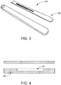
- FIG. 3 shows the mask 61 of FIG. 2 and the respectively coated lens 60.
- FIG. 4 is an embodiment of a 2K molded mask window.
- the mask 61 is in the form of a central window, whereas an opaque material has been molded to form a gasket 62 structure.
- FIG. 5 is a schematic representation of the preparation of a lens-mask system.
- the mask 61 is formed from an ink layer, a binder layer and a resin sheet.
- the prepared product is formed into the desired shape of the lens.
- the formed layers are subsequently injection-molded with a clear resin to form the lens-mask system.
- FIG. 6 is a schematic representation of 2K molded lens-mask system with tinted parts (grey parts) and translucent parts (white parts).
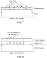
- FIGS. 7 and 8 show schematic representations of embodiments in which the mask is laser etched.
- a paint or opaque coating is applied on the lens and the desired pattern is formed afterwards by the laser etching technique.
- a transmissive coating ( FIG. 8 ) is applied on the etched parts in order to provide a smooth coating for the subsequent application of the transparent and/or translucent coating.
- FIGS. 9 and 10 is a schematic view of the inventive system having an additional coating with a low refractive index.
- the additional coating has been laser etched similar to the mask, whereas in FIG. 10 , the low refractive index coating is translucent and has not been etched.
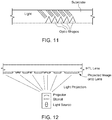
- FIG. 11 is a schematic representation of an embodiment of the invention having optic shapes on the mask.
- the optic shapes refract light to different spectral colors thereby creating and illuminating colored pattern.
- FIG. 12 is a schematic representation of an embodiment with an projector as the mask.
- the projector projects the desired image onto the inner side of the lens (60) so that it can be viewed from the outside of the lens.
- FIG. 13 shows a schematic representation of a motor vehicle 1 according to an example.
- This motor vehicle 1 includes the covering device 3.
- the covering device 3 shown here as a one-piece covering device, includes a shaped element 5 which can be produced by a method of injection molding and simulates or represents the desired shape of the corresponding side part of the motor vehicle 1.
- the form element 5 is covered with a cover in the form of a chromium coating. In this case, it covers or is arranged on the entire outwardly pointing surface area of the element 5.
- the corresponding area is highlighted hatched. This clearly shows that the covering device 3 extends laterally and in the longitudinal direction of the motor vehicle 1 as a roof trim strip 42 above the door region 40, from a position 9 in the region of the A pillar of the motor vehicle 1 continuously to a position 11 in the region of the C.
- the covering device 3 could cover a door region 40, preferably from one pillar part to the other pillar part of the same door area 40 or as a roof covering 43, at least a portion of the roof 41 of the motor vehicle 1, whereby the roof covering 43 extends from a position 9 in the region of an A-pillar of the motor vehicle 1 could extend continuously to at least one position 11 in the region of a C-pillar of the motor vehicle 1.
- the covering device 3 has a light source 21 (not shown in FIG. 1 ) (see FIGS. 4-6 ) for emitting light, which is covered here in plain view from the outside by the form element 5 or lens 7.
- a portion of the light emitted by the light source can pass through the form element 5 and the lens 7 in at least a first region 13 of the covering device 3, which is located in the region of the C-pillar of the motor vehicle 1 to the outside.
- the mold element 5 and the lens 7 has a passage opening 15.
- a display means 17 part of the covering device 3 is arranged in the form of an emblem.
- the display means 17 is partially translucent configured and thus translucent from the back with light of the light source 21, which emerges visible in accordance with the translucent points to the outside.
- the covering device 3 has a light source 21 (not shown in FIG. 13 ) (see FIGS. 16-18 ) for emitting light, which is covered here in plain view from the outside by the form element 5 or lens 7.
- a portion of the light emitted by the light source can pass through the form element 5 and the lens 7 in at least a first region 13 of the covering device 3, which is located in the region of the C-pillar of the motor vehicle 1 to the outside.
- the mold element 5 and the lens 7 has a passage opening 15.
- a display means 17 part of the covering device 3 is arranged in the form of an emblem.
- the display means 17 is partially translucent configured and thus translucent from the back with light of the light source 21, which emerges visible in accordance with the translucent points to the outside.
- the light from a light source 21 encompassed by the covering device 3 can be seen in a first region 13 of the covering device 3, which is present both in the form element 5 and in the lens 7 is designed translucent, escape and thus cause a flat luminous impression.
- Fig. 14 shows a schematic representation of a motor vehicle 1 according to the invention according to the third aspect of the invention, a further embodiment.
- the elements and the mode of operation of the multi-part covering device 3' according to the invention largely correspond to the elements and functionalities shown in FIG. 13 , with the individual parts of the multi-part covering device 3' being arranged on the two doors 40 as mutually movable regions of the motor vehicle 1.
- the part of the covering device 3 'on the front door 40 is designed separately from the other part on the rear door 40.
- On the roof 41 no covering device is arranged.
- the embodiments of Figures 1 and 2 can be combined with each other.
- the embodiment of the covering device 3' differs from the covering device 3 of FIG. 13 in terms of its physical shape.
- the covering device 3' does not extend laterally above the windows of the motor vehicle 1 as a door shaft strip 46.
- the position of the display means 17 is different. This emphasizes the high freedom of design, which is made possible by the covering devices 3, 3' according to the invention.
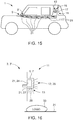
- FIG. 15 shows a schematic representation of a motor vehicle 1 according to the invention in a further embodiment.
- This has a multi-part covering device 3' according to the invention, the elements and functions of which correspond to the embodiments of FIGS. 13 and 14 as far as possible.
- each of the light sources 21 is distributed to different positions behind the mold element 5 and the lens 7.
- the mold element 5 and the lens 7 are each translucent in this area.
- a planar lighting effect along the entire side surface of the motor vehicle 1 is achieved.
- light guides (not explicitly shown in FIG. 15 ) covered by the covering device 3' are used. These also direct the light from the individual light sources 21 to other locations within the respective first region, whereby the illumination effect is more uniform.
- the light sources 21 preferably include light-emitting diodes.
- a further light source, which is not recognizable in FIG. 3 is arranged behind the display means 17.
- FIG. 16 shows a schematic cross-sectional illustration in a further embodiment of a covering device 3, 3 'according to the invention.
- the covering device 3, 3' has two light sources 21. Namely on the one hand a light emitting diode as a display device 24, the light passes in the emission direction 25 in a first translucent region 13 through the mold element 5 and the lens 7. On the other hand, a projection device 27, the light of which passes in the emission direction 29 in another first region 13 through a passage opening in the mold element 5 and in the lens 7 there through. In this case, a logo 33 is projected onto the ground 31 by the projection device 27 on a surface 31 of the floor below the covering device 3, 3'.
- FIG. 17 shows a schematic representation of an embodiment of the covering device 3,3' in the lateral section, from which the layers of the form element 5 and lens 7 emerge in a particularly clear manner.
- the mold element 5 forms a cavity to the outside of the motor vehicle 1, in which the light source 21 is received.
- the lens 7 is arranged on the outside 5a of the element (5) in order to cover it to the outside.
- On the inside 5i of the form element is a display means 17, preferably at least one emblem disposed.
- the display means 17 is at least partially translucent, in particular transparent, configured and arranged in the first region 13, wherein at least part of the light emitted by the light source 21 passes through the mold element 5 and/or the lens 7 after can pass outside.
- the light source 21 is here connected via the display means 17 with the inner side 5i of the form element 5 wherein the first region 13 covers the light source 21.
- the light source 21 may be a planar arrangement of a plurality of LEDs or a planar OLED.
- the lens 7 includes at least one metal coating, which is preferably produced and/or producible by means of thin-film technology.
- the metal coating may include a chromium-containing layer, preferably the chromium-containing layer is a chromium alloy or a doped chromium layer.
- the lens 7 covers the display means 17 from.
- FIG. 18 shows a further embodiment of the covering device according to the invention in a lateral section.
- the light source 21 is not arranged on the display means 17.
- the covering device 3, 3' further includes a light guide 18 which distributes the light emitted by the light source 21 to the first area 13 by extending from the light source 21 to the display means 17.
- the light source 21 is embodied here as an LED or as a linear chain of LEDs.
- the covering device 3, 3' could also include a plurality of optical fibers 18 and a plurality of first regions (13), wherein at least a first of the optical fibers 18 distributes light to at least one of the first regions 13 and at least a second of the optical fibers 18 emits light distributed at least one other first area 13.
- first of the optical fibers 18 distributes light to at least one of the first regions 13 and at least a second of the optical fibers 18 emits light distributed at least one other first area 13.
Applications Claiming Priority (1)
| Application Number | Priority Date | Filing Date | Title |
|---|---|---|---|
| US16/738,513 US11346523B2 (en) | 2018-03-13 | 2020-01-09 | Light emitting system, a design element, a rear view device, a covering device, and a body component of a vehicle |
Publications (1)
| Publication Number | Publication Date |
|---|---|
| EP3848628A1 true EP3848628A1 (de) | 2021-07-14 |
Family
ID=74105951
Family Applications (1)
| Application Number | Title | Priority Date | Filing Date |
|---|---|---|---|
| EP21150608.4A Pending EP3848628A1 (de) | 2020-01-09 | 2021-01-07 | Lichtemittierendes system, designelement, rückblickvorrichtung, abdeckvorrichtung und karosserieteil eines fahrzeugs |
Country Status (1)
| Country | Link |
|---|---|
| EP (1) | EP3848628A1 (de) |
Citations (9)
| Publication number | Priority date | Publication date | Assignee | Title |
|---|---|---|---|---|
| US20090257241A1 (en) * | 2005-02-04 | 2009-10-15 | Adac Plastics, Inc. | Trim component with concealed indicium |
| WO2011075796A1 (en) | 2009-12-24 | 2011-06-30 | Co-Operative Research Centre For Advanced Automotive Technology Ltd | Plastic automotive mirrors |
| US20130130674A1 (en) * | 2011-11-14 | 2013-05-23 | Magna Mirrors Of America, Inc. | Illumination module for vehicle |
| WO2013110122A1 (en) | 2012-01-24 | 2013-08-01 | SMR Patents S.à.r.l. | Chromium-based reflective coating |
| DE102015205630A1 (de) * | 2014-03-28 | 2015-10-01 | Kunststoff-Technik Scherer & Trier Gmbh & Co. Kg | Abdeckungseinrichtung, System, Karosseriebauteil, Karosseriebauteilsystem und Fahrzeug |
| EP3228501A1 (de) * | 2016-03-17 | 2017-10-11 | Seat, S.A. | Beleuchtungsvorrichtung für eine äussere abdeckung auf einer seite eines fahrzeugs |
| US20190176692A1 (en) * | 2016-08-09 | 2019-06-13 | Daimler Ag | Illuminated decorative part |
| US20190323676A1 (en) * | 2018-03-13 | 2019-10-24 | Motherson Innovations Company Ltd. | Vehicular components having chromium-based reflective coating at least partially permeable to light |
| US20190324362A1 (en) * | 2018-04-19 | 2019-10-24 | Ford Global Technologies, Llc | Vehicle puddle lamp assembly |
-
2021
- 2021-01-07 EP EP21150608.4A patent/EP3848628A1/de active Pending
Patent Citations (9)
| Publication number | Priority date | Publication date | Assignee | Title |
|---|---|---|---|---|
| US20090257241A1 (en) * | 2005-02-04 | 2009-10-15 | Adac Plastics, Inc. | Trim component with concealed indicium |
| WO2011075796A1 (en) | 2009-12-24 | 2011-06-30 | Co-Operative Research Centre For Advanced Automotive Technology Ltd | Plastic automotive mirrors |
| US20130130674A1 (en) * | 2011-11-14 | 2013-05-23 | Magna Mirrors Of America, Inc. | Illumination module for vehicle |
| WO2013110122A1 (en) | 2012-01-24 | 2013-08-01 | SMR Patents S.à.r.l. | Chromium-based reflective coating |
| DE102015205630A1 (de) * | 2014-03-28 | 2015-10-01 | Kunststoff-Technik Scherer & Trier Gmbh & Co. Kg | Abdeckungseinrichtung, System, Karosseriebauteil, Karosseriebauteilsystem und Fahrzeug |
| EP3228501A1 (de) * | 2016-03-17 | 2017-10-11 | Seat, S.A. | Beleuchtungsvorrichtung für eine äussere abdeckung auf einer seite eines fahrzeugs |
| US20190176692A1 (en) * | 2016-08-09 | 2019-06-13 | Daimler Ag | Illuminated decorative part |
| US20190323676A1 (en) * | 2018-03-13 | 2019-10-24 | Motherson Innovations Company Ltd. | Vehicular components having chromium-based reflective coating at least partially permeable to light |
| US20190324362A1 (en) * | 2018-04-19 | 2019-10-24 | Ford Global Technologies, Llc | Vehicle puddle lamp assembly |
Similar Documents
| Publication | Publication Date | Title |
|---|---|---|
| US11512830B2 (en) | Light emitting system, a design element, a rear view device, a covering device, and a body component of a vehicle | |
| JP6880418B2 (ja) | 車両用発光部品及び車両用ドアライニング | |
| US10279736B2 (en) | Vehicle interior trim assembly configured to form a light pattern having an emblem shape at the front of a trim part such as an air bag cover | |
| KR101219341B1 (ko) | 자동차용 발광 가니쉬 | |
| CN102774314B (zh) | 车辆外表面的装饰件、脚灯系统及车辆用装饰件 | |
| US7396147B2 (en) | Back-illuminated panel with ultraviolet protection | |
| CN108602469B (zh) | 被照明的标识徽记 | |
| EP2628638B1 (de) | Automobiles Körperelement, umfassend eine Lichtquelle auf der inneren Fläche | |
| US11519585B2 (en) | Covering devices for use with vehicle parts | |
| US10207632B2 (en) | Vehicle body element comprising a translucent body and method for producing such a body | |
| CN112823096A (zh) | 可选择性照明的金属外观装饰件以及其制造方法 | |
| CN113195307A (zh) | 背光照明的车身零件 | |
| CN117561561A (zh) | 用于制造用于车辆的发亮构件的方法 | |
| US20240059212A1 (en) | Light assembly, vehicle design element, rear view device and door finisher | |
| US11485281B2 (en) | Light assembly, method for reducing light loss, vehicle design element and rear view device | |
| EP3848628A1 (de) | Lichtemittierendes system, designelement, rückblickvorrichtung, abdeckvorrichtung und karosserieteil eines fahrzeugs | |
| EP3853068B1 (de) | Fahrzeugleuchtenbaugruppe | |
| US20240092281A1 (en) | Cladding part for a motor vehicle | |
| WO2003040614A1 (en) | Automotive lamp | |
| WO2023187843A1 (en) | A motor-vehicle interior component with a backlit decorative panel | |
| KR20220069409A (ko) | 차량 가니쉬 | |
| CN117781227A (zh) | 用于机动车辆的外部覆层部分的照明系统 | |
| CN117083201A (zh) | 用于机动车的装饰覆盖件以及具有这种覆盖件的车辆 |
Legal Events
| Date | Code | Title | Description |
|---|---|---|---|
| PUAI | Public reference made under article 153(3) epc to a published international application that has entered the european phase |
Free format text: ORIGINAL CODE: 0009012 |
|
| STAA | Information on the status of an ep patent application or granted ep patent |
Free format text: STATUS: THE APPLICATION HAS BEEN PUBLISHED |
|
| AK | Designated contracting states |
Kind code of ref document: A1 Designated state(s): AL AT BE BG CH CY CZ DE DK EE ES FI FR GB GR HR HU IE IS IT LI LT LU LV MC MK MT NL NO PL PT RO RS SE SI SK SM TR |
|
| STAA | Information on the status of an ep patent application or granted ep patent |
Free format text: STATUS: REQUEST FOR EXAMINATION WAS MADE |
|
| 17P | Request for examination filed |
Effective date: 20211216 |
|
| RBV | Designated contracting states (corrected) |
Designated state(s): AL AT BE BG CH CY CZ DE DK EE ES FI FR GB GR HR HU IE IS IT LI LT LU LV MC MK MT NL NO PL PT RO RS SE SI SK SM TR |
|
| RAP3 | Party data changed (applicant data changed or rights of an application transferred) |
Owner name: MOTHERSON INNOVATIONS COMPANY LIMITED |
|
| RAP3 | Party data changed (applicant data changed or rights of an application transferred) |
Owner name: MOTHERSON INNOVATIONS COMPANY LIMITED |
|
| STAA | Information on the status of an ep patent application or granted ep patent |
Free format text: STATUS: EXAMINATION IS IN PROGRESS |
|
| 17Q | First examination report despatched |
Effective date: 20220603 |
|
| P01 | Opt-out of the competence of the unified patent court (upc) registered |
Effective date: 20230616 |
|
| GRAP | Despatch of communication of intention to grant a patent |
Free format text: ORIGINAL CODE: EPIDOSNIGR1 |
|
| STAA | Information on the status of an ep patent application or granted ep patent |
Free format text: STATUS: GRANT OF PATENT IS INTENDED |
|
| INTG | Intention to grant announced |
Effective date: 20240112 |