EP3848152B1 - Werkzeugmaschine und bearbeitungsvorrichtung - Google Patents
Werkzeugmaschine und bearbeitungsvorrichtung Download PDFInfo
- Publication number
- EP3848152B1 EP3848152B1 EP19858618.2A EP19858618A EP3848152B1 EP 3848152 B1 EP3848152 B1 EP 3848152B1 EP 19858618 A EP19858618 A EP 19858618A EP 3848152 B1 EP3848152 B1 EP 3848152B1
- Authority
- EP
- European Patent Office
- Prior art keywords
- information
- electric power
- power tool
- unit
- torque
- Prior art date
- Legal status (The legal status is an assumption and is not a legal conclusion. Google has not performed a legal analysis and makes no representation as to the accuracy of the status listed.)
- Active
Links
Images


Classifications
-
- B—PERFORMING OPERATIONS; TRANSPORTING
- B25—HAND TOOLS; PORTABLE POWER-DRIVEN TOOLS; MANIPULATORS
- B25B—TOOLS OR BENCH DEVICES NOT OTHERWISE PROVIDED FOR, FOR FASTENING, CONNECTING, DISENGAGING OR HOLDING
- B25B23/00—Details of, or accessories for, spanners, wrenches, screwdrivers
- B25B23/14—Arrangement of torque limiters or torque indicators in wrenches or screwdrivers
- B25B23/147—Arrangement of torque limiters or torque indicators in wrenches or screwdrivers specially adapted for electrically operated wrenches or screwdrivers
- B25B23/1475—Arrangement of torque limiters or torque indicators in wrenches or screwdrivers specially adapted for electrically operated wrenches or screwdrivers for impact wrenches or screwdrivers
-
- B—PERFORMING OPERATIONS; TRANSPORTING
- B25—HAND TOOLS; PORTABLE POWER-DRIVEN TOOLS; MANIPULATORS
- B25F—COMBINATION OR MULTI-PURPOSE TOOLS NOT OTHERWISE PROVIDED FOR; DETAILS OR COMPONENTS OF PORTABLE POWER-DRIVEN TOOLS NOT PARTICULARLY RELATED TO THE OPERATIONS PERFORMED AND NOT OTHERWISE PROVIDED FOR
- B25F5/00—Details or components of portable power-driven tools not particularly related to the operations performed and not otherwise provided for
- B25F5/02—Construction of casings, bodies or handles
- B25F5/021—Construction of casings, bodies or handles with guiding devices
Definitions
- the present disclosure relates to an electric power tool and a processing apparatus.
- Patent literature 1 discloses a work management apparatus including a work information acquisition unit that acquires work information related to the content of work, a positional information acquisition unit that acquires positional information on a place of work, a workpiece information acquisition unit that acquires workpiece information, and an information management unit that stores the work information, the positional information, and the workpiece information in a storage unit, mapping the information to each other.
- the work management apparatus further includes a determination unit that determines the properness of a work by referring to data for a design drawing. The result of determining the properness of a work is displayed on a display unit.
- JP 2005 177919 A discloses an electric power tool according to the preamble of claims 1 and 3.
- EP 3 135 437 A1 describes an electric tool remote information collection system, comprising an electric tool and a server, wherein an information collection unit of said electric tool collects maintenance warning information and/or research and development reference information; a communication unit sends said maintenance warning information and/or research and development reference information to said server; and said server performs communication with said electric tool to collect said maintenance warning information and/or research and development reference information.
- a beneficial effect of the present invention is: via disposing an information collection unit to collect proper information and send it to a server, an electric tool manufacturer can provide a specific service and product for a user, for example, provide preventive maintenance information for said electric tool and researching and developing specific products for users of a specific area or type.
- the DE 10 2013 016068 A1 relates to a tool and a method for monitoring the condition of a tool.
- the tool comprises a control device for determining status data of the tool, and a display device for displaying the status data determined by the control device.
- DE 10 2017 202286 A1 describes a method of monitoring an electric hand tool including steps of detecting use of the hand tool; determining a cumulative usage time; and granting a device warranty as long as the period of use does not exceed a predetermined maximum period of use.
- EP 2 248 632 A1 describes a wireless data transmitting and receiving system including: a data transmitting unit provided on the rotary shaft of a tightening machine to detect the torque and the rotation angle, the data transmitting unit including a torque sensor disposed so as to be capable of sensing a toque acting on the rotary shaft, a rotation angle sensor disposed so as to be capable of a rotation angle of the rotary shaft, and transmitting means that is electrically connected to the foregoing sensors, and wirelessly transmits signals regarding the torque detected in the torque sensor and the rotation angle detected in the rotation angle sensor; and a data receiving unit including receiving means that receives the transmitted signals regarding the torque and the rotation angle, and display means that displays the signals regarding the torque and the rotation angle received by the receiving means.
- a drill driver is a widely-used tool and is used to tighten a screw or bore a hole.
- An impact driver has an impact mechanism for generating a tightening torque by applying a striking impact in a rotational direction.
- a multi-impact driver has the functions of both a drill driver and an impact driver.
- An impact wrench generates a tightening torque greater than that of an impact driver.
- electric power tools of the same type are available in various product specifications such as the battery back mounted, charging time, maximum tightening torque, availability of manual tightening capability, dimension of the main unit, mass of the main unit, etc. Since there are numerous options for choosing a tool, it is not easy for a user to choose a tool suited to the content of his or her work.
- the disclosure addresses the above-described issue, and a general purpose thereof is to provide a technology necessary to present recommendation information related to the electric power tool to a user. This purpose is achieved by the subject-matter of the independent claims. Particular embodiments are defined in the dependent claims.
- Fig. 1 shows a configuration of an electric power tool system 100
- the electric power tool system 100 includes an electric power tool 1 and a server system 70.
- the server system 70 is a processing apparatus for processing various information transmitted from the electric power tool 1.
- An access point (hereinafter, "AP") 60 is interconnected with the electric power tool 1, which is a wireless LAN client, and is connected to an external network 62 such as the Internet.
- a router 61 is connected to the server system 70 by wire and is connected to the network 62.
- the electric power tool 1 and the server system 70 are communicably connected via the network 62.
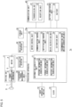
- Fig. 2 shows a functional block of the electric power tool 1 according to the embodiment.
- the electric power tool 1 includes a driving unit 3, a processing apparatus 10, a user operation switch 18, a clock 19, a tightening torque measurement unit 30, an acceleration detector 31, a notification interface 32, a storage unit 33, a communication unit 40, a battery 50, and a battery monitoring unit 51.
- the clock 19 is a real-time clock. The clock 19 generates current date and time information and supplies the information to the processing apparatus 10.
- the battery 50 is a secondary battery and is housed in a battery pack separate from the main body of the tool.
- the battery pack is configured to be removably attached to the lower end of the main body of the tool.
- the battery 50 supplies electric power to the constituting elements of the electric power tool 1 including a motor 4. Since battery packs of different capacities can be attached to or detached from the main body of the tool, it is preferable for a user to choose a battery pack suited to the content of his or her work.
- the driving unit 3 includes the motor 4, which is driving source, and a power transmission mechanism 6 coupled to a motor shaft 5 of the motor 4, and drives an output shaft 7.
- a front-end tool mount 8 is coupled to the output shaft 7, and a front-end tool such as a driver that applies a tightening torque to a tightened member is adapted to be mounted on the front-end tool mount 8.
- the power transmission mechanism 6 transmits the rotational output of the motor 4 to the output shaft 7.
- the power transmission mechanism 6 may include a planetary gear deceleration mechanism in mesh with a pinion gear attached to the motor shaft 5.
- the electric power tool 1 is an impact driver or a multi-impact driver, for example, the power transmission mechanism 6 includes an impact mechanism for applying an intermittent rotary striking force to the output shaft 7.
- the tightening torque measurement unit 30 measures the tightening torque of the tightened member (screw member).
- the tightening torque measurement unit 30 may include a magnetostrictive torque sensor attached to the output shaft 7 and a rotation angle sensor of the output shaft 7.
- the torque sensor uses a coil provided in a non-rotated part to detect the variation in magnetic permeability determined by the axial distortion caused by applying a torque to the output shaft 7 and outputs a voltage signal determined by the distortion.
- the rotation angle sensor outputs the rotation angle of the output shaft 7.
- the tightening torque measurement unit 30 uses the voltage signal determined by the distortion and the rotation angle of the output shaft 7 to calculate the tightening torque of the screw member.
- the tightening torque measurement unit 30 outputs the measured value of the tightening torque to the processing apparatus 10 as torque information at a first sampling period.
- the tightening torque measurement unit 30 may measure the tightening torque only when the user operation switch 18 is manipulated by the user.
- the acceleration detector 31 detects the acceleration of the electric power tool 1.
- the acceleration detector 31 may include a three-axis acceleration sensor and a three-axis gyro sensor.
- the acceleration sensor and the gyro sensor may have a capacitance-type or piezoelectric structure.
- the detected acceleration is used in the process of identifying the posture of the electric power tool 1 and the process of calculating the moving distance of the electric power tool 1.
- the acceleration detector 31 outputs the detected acceleration value to the processing apparatus 10 at a second sampling period.
- the acceleration detector 31 may detect the acceleration of the electric power tool 1 while the main power supply is being turned on.
- the battery monitoring unit 51 monitors the status of the battery 50.
- the battery monitoring unit 51 includes a voltage measurement circuit for detecting the voltage value of the battery 50 for the purpose of preventing over charge or over discharge.
- the battery monitoring unit 51 also includes a current measurement circuit for the purpose of preventing an overcurrent.
- the battery monitoring unit 51 also includes a temperature measurement circuit for the purpose of detecting an abnormal temperature.
- the battery monitoring unit 51 outputs the measured voltage value, current value, and temperature value to the processing apparatus 10 as battery information indicating the status of the battery 50 at a third sampling period.
- the communication unit 40 includes a transmission unit 41 and a reception unit 42.
- the communication unit 40 may be a module configured to communicate wirelessly with the AP 60 according to a communication protocol such as the IEEE802.11 protocol.
- the communication unit 40 may also include a wireless communication function in the fourth-generation mobile communication system.
- the communication unit 40 may not be a wireless communication module but a module configured to communicate with an external device by wire via, for example, a USB cable.
- the notification interface 32 is an output interface for outputting information to the user.
- the notification interface 32 may include a speaker for audio output of information and/or a display for outputting information on a screen.
- the storage unit 33 is a memory and includes a read only memory (ROM) and a random access memory (RAM).
- the ROM stores at least identification information (tool ID) for identifying the electric power tool 1.
- the ROM further stores a control program used by the motor control unit 20.
- the RAM stores the information transmitted from the transmission unit 41 temporarily and stores the information received by the reception unit 42 temporarily.
- the electric power tool or the entity that executes the method according to the disclosure is provided with a computer.
- the computer is comprised of a processor that operates in accordance with the program as a main hardware feature.
- the disclosure is non-limiting as to the type of the processor so long as the function is realized by running the program.
- the processor is comprised of one or a plurality of electronic circuits including a semiconductor integrated circuit (IC) or a large-scale integration (LSI).
- IC and LSI may change depending on the integration degree, and the processor may be comprised of a system LSI, a very large scale integration (VLSI), or an ultra large scale integration (USLI).
- a field programmable gate array (FPGA) programmed after the LSI is manufactured, or a reconfigurable logic device, in which the connections inside the LSI are reconfigurable or the circuitry blocks inside the LSI can be set up, can be used for the same purpose.
- the plurality of electronic circuits may be integrated in one chip or provided in a plurality of chips.
- the plurality of chips may be aggregated in one device or provided in a plurality of devices.
- the program is recorded in a non-transitory recording medium such as a computer-readable ROM, optical disk, and hard disk drive.
- the program may be stored in a recording medium in advance or supplied to a recording medium via wide area communication network including the Internet or the like.
- the processing apparatus 10 is implemented by a computer carried on a control board.
- the processing apparatus 10 has the function for integrated control of the electric power tool 1 and performs various processes related to the electric power tool 1.
- the processing apparatus 10 includes an information acquisition unit 11, a motor control unit 20, a communication control unit 21, a notification control unit 22, and a drive restriction unit 23.
- the information acquisition unit 11 includes a posture information acquisition unit 12, a torque information acquisition unit 13, and a battery information acquisition unit 14.
- the grip of the main body of the tool is provided with a user operation switch 18 that can be manipulated by the user.
- the user operation switch 18 may be a trigger switch that can be pulled by the user for manipulation to rotate the motor 4.
- the motor control unit 20 controls the rotation of the motor 4 in accordance with the on operation of the user operation switch 18 performed by the user. More specifically, the motor control unit 20 controls the current applied to the motor 4 in accordance with how much the user operation switch 18 is manipulated to adjust the the number of revolutions of the motor.
- workers repeat a predetermined work and can use the electric power tool 1 of a type most suitable for the work. Meanwhile, users like interior construction workers and carpenters are required to do various works required of them by using a single electric power tool 1 in their personal possession. The user can reduce the workload or make the work efficient by using the electric power tool 1 suited to his or her work.
- the server system 70 has the function of collecting various information indicating the usage situation from the electric power tool 1 and estimating the content of work performed by the user. By estimating the content of work performed by the user, the server system 70 derives, as recommendation information, the type of the electric power tool 1 suited to the estimated content of work, the optimum value of the operation parameter in the electric power tool 1 being used, etc.
- the recommendation information is communicated to the user and is used, for example, as reference information referred to when the user purchase the electric power tool 1 in the future.
- the work hours of the user serves as one criterion to estimate the level of load imposed on the user during a work. It can be said that the longer the work hours per day, the heavier the workload on the user, and the shorter the work hours, the lighter the workload on the user.
- Another criterion is the work posture of the user. It is observed that a work performed by orienting the electric power tool 1 downward is relatively easy, but a work performed by orienting the electric power tool 1 upward imposes a heavy load on the arm so that the fatigue builds up easily.
- the electric power tool 1 is often configured such that a plurality of battery packs having different capacities can be mounted.
- a battery pack having a large capacity makes it possible to work for a long time continuously but has a drawback in that it is heavier than a battery pack having a small capacity. For this reason, the weight of a battery pack affects the workload on the user.
- information for identifying the work hours or work posture, and, moreover, information on the usage status of the battery are necessary in order to estimate the level of load on the user.
- the information acquisition unit 11 acquires posture information for identifying the posture of the electric power tool 1 and torque information indicating the measured value of tightening torque, in association with time information related to the time when the respective information is acquired.
- the information acquisition unit 11 may acquire battery information indicating the status of the battery 50, in association with time information related to the time when the battery information is acquired.
- the posture information acquisition unit 12 acquires the detected acceleration value from the acceleration detector 31 as posture information for identifying the posture of the electric power tool 1.
- the posture information acquisition unit 12 stores the acquired posture information and the time information related to the time when the posture information is acquired in the storage unit 33, mapping the posture information to the time information.
- the torque information acquisition unit 13 acquires torque information indicating the measured value of tightening torque produced by the front-end tool from the tightening torque measurement unit 30.
- the torque information acquisition unit 13 stores the acquired torque information and the time information related to the time when the torque information is acquired in the storage unit 33, mapping the torque information to the time information.
- the battery information acquisition unit 14 acquires battery information indicating the status of the battery 50 from the battery monitoring unit 51.
- the battery information acquisition unit 14 stores the acquired battery information and the time information related to the time when the battery information is acquired in the storage unit 33, mapping the battery information to the time information.
- the time information mapped to the respective information may be the absolute time information indicating the current time supplied from the clock 19.
- the mapped time information may be the relative time information indicating the time elapsed since the reference time (e.g., the date and time of manufacturing or the date and time of first use).
- the storage unit 33 stores the posture information, torque information, battery information, and the time information related to the time when the respective information is acquired, mapping the information to each other.
- the communication control unit 21 controls the transmission operation performed by the transmission unit 41 and the reception operation performed by the reception unit 42.
- the communication unit 40 is connected to the server system 70 via the network 62.
- the transmission unit 41 transmits at least the posture information, the torque information, and the time information related to the time when the respective information is acquired to the server system 70 (external apparatus).
- the transmission unit 41 may transmit the battery information and the time information indicating the time when the battery information is acquired to the server system 70.
- the communication control unit 21 may read the information stored in the storage unit 33 periodically and cause the transmission unit 41 to transmit the information to the server system 70.
- the communication control unit 21 may cause the transmission unit 41 to transmit information for a day stored in the storage unit 33, i.e. the posture information, torque information, battery information, and time information related to the time when the respective information is acquired, once a day to the server system 70.
- the communication control unit 21 may read the information stored in the storage unit 33 when main power supply was turned on previously and cause the transmission unit 41 to transmit the read information to the server system 70.
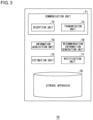
- Fig. 3 shows functional blocks of the server system 70
- the server system 70 includes a communication unit 71, an information acquisition unit 74, an estimation unit 75, a recommendation information generation unit 76, a notification unit 77, and a storage apparatus 78.
- the communication unit 71 includes a reception unit 72 and a transmission unit 73.
- the server system 70 may be operated and managed by, for example, an entity manufacturing the electric power tool 1.
- Fig. 1 shows that the server system 70 is connected only to one electric power tool 1, but the server system 70 is connected to a plurality of electric power tools 1 and receives various information acquired by the respective electric power tools 1.
- the transmission unit 41 in the electric power tool 1 maps various information necessary to estimate the content of work to the tool ID of the electric power tool 1 and transmits the information to the server system 70.
- the reception unit 72 receives the various information transmitted from the electric power tool 1, and the storage apparatus 78 stores the received various information, mapping the information to the tool ID of the electric power tool 1.
- the information acquisition unit 74 reads and acquires, from the storage apparatus 78, the posture information for identifying the posture of the electric power tool 1, torque information indicating the measured value of tightening torque, and time information related to the time when the torque information and the posture information are acquired in the electric power tool 1.
- the following description concerns a case in which the information acquisition unit 74 acquires various information for a day in one electric power tool 1, and the estimation unit 75 estimates the content of a day's work.
- the estimation unit 75 analyzes a day's work in which the electric power tool 1 is used and estimates the content of work by referring to the result of analysis, based on the posture information, torque information, and time information for a day acquired by the information acquisition unit 74.
- the estimation unit 75 also uses the battery information and the associated time information to estimate the content of work in which the electric power tool 1 is used.
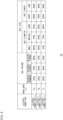
- Fig. 4 shows an example of the result of analyzing a day's work in which each of the electric power tools A-C is used.
- the estimation unit 75 may analyze the various information over a plurality of days to derive a day's analysis result shown in Fig. 4 .
- the "work hours" field shows a day's work hours.
- a day's work hours may simply be a total hours for which the main power supply is turned on.
- a day's work hours may be a total hours for which the user operation switch 18 is manipulated.
- the hours for which the user operation switch 18 is manipulated can be derived by referring to the torque information or the posture information (acceleration information).
- the "tool posture” field shows the posture of the electric power tool 1 being used in the work.
- the estimation unit 75 calculates the proportion of a tool posture in a day by referring to the posture information on the electric power tool 1.
- the proportion may be calculated by referring to the number of tightened members but may be calculated by referring to the work hours required to tighten the respective tightened members.
- the estimation unit 75 may calculate the work hours required to tighten the respective tightened members by using the torque information and calculate the total tightening work hours in the respective orientations to derive the proportion of a tool posture, by referring to the posture and the tightening work hours of the respective tightened members.
- the bolt type is categorized according to the bolt diameter and bolt length.
- the estimation unit 75 analyzes the temporal change in the torque value measured during a work by referring to the torque information and categorizes the bolt diameter into one of small, medium, and large.
- the estimation unit 75 also identifies the time required for the bolt to be seated by referring to the torque information and categorizes the bolt length into one of short and long.
- the estimation unit 75 may determine whether the bolt length is short or long depending on whether the time required for the bolt to be seated is shorter or longer than a threshold value Tth.
- the estimation unit 75 may estimate the remaining battery level by referring to the battery information for each tightening work. For example, the estimation unit 75 can estimate that the battery 50 has become deteriorated by estimating the remaining battery level for each tightening work. If there is enough remaining battery level at the end of a day's work, the estimation unit 75 may determine that the battery capacity may be smaller, though the determination depends on a day's work hours. In this way, the estimation unit 75 may analyze a day's work from the perspective of remaining battery level.
- the estimation unit 75 analyzes a day's work in which the electric power tool 1 is used and estimates the content of work in which the electric power tool 1 is used by referring to the analysis result.
- Fig. 4 shows analysis results of three electric power tools A-C.
- the process in the estimation unit 75 and the recommendation information generation unit 76 related to the analysis result of the electric power tool A will be described.
- the estimation unit 75 estimates that the content of work in which the electric power tool A is used is characterized by the fact that the electric power tool A is often used in the upward oriented posture, bolts having a small diameter are tightened in a majority of works, and the work hours Ta are relatively short. That bolts having a small diameter are tightened in a majority of works means that high output performance is not required of the electric power tool A. That the tool is often used in the upward oriented posture means that the user's arm is likely to be heavily loaded.
- the recommendation information generation unit 76 generates recommendation information adapted to the content of work estimated by the estimation unit 75.
- the recommendation information is provided to the user of the electric power tool 1 and may recommend an electric power tool suited to the content of work to the user.
- the estimation unit 75 estimates that the work hours of the electric power tool A are relatively short, high output performance is not required in a majority of works, and the tool is often used in the upward oriented posture in a work. Based on this, the recommendation information generation unit 76 may generate recommendation information recommending a type of lightweight electric power tool having only low output performance for purchase in the future. If the remaining battery level is sufficient at the end of a day's work, the recommendation information generation unit 76 may generate recommendation information to recommend a purchase of a battery pack having a small battery capacity and a light weight.
- the notification unit 77 causes the transmission unit 73 to transmit the recommendation information generated by the recommendation information generation unit 76 to the electric power tool A.
- the notification unit 77 may cause the transmission unit 73 to transmit the recommendation information to a terminal apparatus associated with the electric power tool A (e.g., a mobile phone set of the user of the electric power tool A) instead of to the electric power tool A. In either case, the transmission unit 73 transmits the recommendation information so that the user of the electric power tool A can confirm.
- the server system 70 may be comprised of one or a plurality of apparatuses.
- the server system 70 may include a collection apparatus for collecting various information transmitted from the electric power tool 1 and an estimation apparatus for estimating the content of work of the electric power tool 1 by using the various information thus collected.
- the communication unit 71 and the storage apparatus 78 shown in Fig. 3 are provided as configurations on the side of the collecting apparatus, and the information acquisition unit 74, the estimation unit 75, and recommendation information generation unit 76, and the notification unit 77 are provided as configurations on the side of the estimation apparatus.
- the reception unit 42 receives the transmitted recommendation information.
- the notification control unit 22 causes the notification interface 32 to communicate the recommendation information.
- the notification interface 32 provides an audio output of the recommendation information from the speaker or provides a screen output of the recommendation information from a display. The user can know the information recommended in relation to the electric power tool 1 being used, by referring to the content communicated from the notification interface 32 and can address the situation by exchanging the battery pack or purchase a new tool as necessary.
- the notification control unit 22 may cause the notification interface 32 to communicate the recommendation information repeatedly until the user performs a confirmation operation.
- the confirmation operation may, for example, be an operation to press a confirmation button provided in the electric power tool 1.
- This causes notification control unit 22 to ensure that the recommendation information is communicated to the user.
- the drive restriction unit 23 restrict the motor 4 from being driven while the recommendation information is being communicated by the notification interface 32.
- the drive restriction unit 23 restricts the motor control unit 20 from driving the motor 4 while the notification interface 32 is communicating the recommendation information even if the user operation switch 18 is turned on by the user. This ensures that the electric power tool 1 is available for use after the recommendation information is communicated properly to the user.
- the recommendation information generation unit 76 generates recommendation information including a tool type recommended for purchase.
- the recommendation information generation unit 76 may generate information indicating whether the current tool is proper.
- the recommendation information generation unit 76 may generate information indicating that the electric power tool A used by the user is most suitable.
- the recommendation information generation unit 76 may generate the optimum operation parameter as recommendation information.
- the server system 70 in the electric power tool system 100 estimates the content of work in which the electric power tool 1 is used to generate the recommendation information.
- a description will be given below of a case in which the electric power tool 1 estimates the content of work performed by using the electric power tool 1 on its own.
- Fig. 5 shows another functional block of an electric power tool 1a according to the embodiment.
- the electric power tool 1a includes the driving unit 3, a processing apparatus 10a, the user operation switch 18, the clock 19, the tightening torque measurement unit 30, the acceleration detector 31, the notification interface 32, the storage unit 33, the communication unit 40, the battery 50, and the battery monitoring unit 51.
- the processing apparatus 10a of the electric power tool 1a shown in Fig. 5 includes an estimation unit 24 and a recommendation information generation unit 25 and has the function of estimating the content of work and generating recommendation information.
- the information acquisition unit 11 reads and acquires, from the storage unit 33, the posture information for identifying the posture of the electric power tool 1a, the torque information indicating the measured value of tightening torque, and the time information related to the time when the torque information and the posture information are acquired in the electric power tool 1a.
- the information acquisition unit 11 may read and acquire the battery information and the time information related to the time when the battery information is acquired from the storage unit 33.
- the estimation unit 24 analyzes a day's work in which the electric power tool 1a is used and estimates the content of work by referring to the result of analysis, based on the posture information, torque information, and time information for a day acquired by the information acquisition unit 11.
- the estimation unit 24 may also use the battery information and the associated time information to estimate the content of work in which the electric power tool 1 is used.
- the recommendation information generation unit 25 generates recommendation information adapted to the content of work estimated.
- the estimation process performed by the estimation unit 24 and the recommendation information generation process performed by the recommendation information generation unit 25 may be identical to the information generation process performed by the estimation unit 75 and the recommendation information generation process performed by the recommendation information generation unit 76 in the server system 70, respectively.
- the electric power tool 1a estimates the content of work on its own so that the transmission unit 41 in the electric power tool 1a does not transmit the various information for estimating the content of work to the server system 70.
- the transmission unit 41 in the electric power tool 1a may transmit the various information for estimating the content of work to the server system 70.
- the present disclosure can be used in the fields of electric power tools and processing apparatus.
Landscapes
- Engineering & Computer Science (AREA)
- Mechanical Engineering (AREA)
- Portable Power Tools In General (AREA)
- Details Of Spanners, Wrenches, And Screw Drivers And Accessories (AREA)
- General Factory Administration (AREA)
Claims (3)
- Elektrowerkzeug (1), aufweisend:eine Abtriebswelle (7), an der ein Vorderend-Werkzeug montiert werden kann;einen Kraftübertragungsmechanismus (6), der eine Rotationsausgabe einer Antriebsquelle (4) an die Abtriebswelle (7) überträgt;eine Stellungsinformations-Erfassungseinheit (12), die Stellungsinformationen zum Identifizieren einer Stellung des Elektrowerkzeugs (1) erfasst;eine Drehmomentinformations-Erfassungseinheit (13), die Drehmomentinformationen erfasst, die einen gemessenen Wert des Anzugsmoments angeben, das von dem Vorderend-Werkzeug erzeugt wird;eine Übertragungseinheit (41), die die Stellungsinformationen, die Drehmomentinformationen und Zeitinformationen, die sich auf einen Zeitpunkt beziehen, zu dem die jeweiligen Informationen erfasst werden, an eine externe Vorrichtung (70) überträgt;dadurch gekennzeichnet, dass sie ferner aufweist:eine Empfangseinheit (42), die Empfehlungsinformationen empfängt, die anhand der Stellungsinformationen, der Drehmomentinformationen und der Zeitinformationen erzeugt werden;eine Benachrichtigungsschnittstelle (32), die die empfangenen Empfehlungsinformationen übermittelt; undeine Antriebseinschränkungseinheit (23), die die Antriebsquelle daran hindert, angetrieben zu werden, während die Empfehlungsinformationen von der Benachrichtigungsschnittstelle übermittelt werden, wobeidie Empfehlungsinformationen ein Merkmal des Elektrowerkzeugs sind, das für einen geschätzten Arbeitsinhalt geeignet ist oder ein optimaler Wert eines Betriebsparameters in dem Elektrowerkzeug ist, das verwendet wird.
- Elektrowerkzeug (1) nach Anspruch 1, aufweisend:eine Batterie (50), welche die Antriebsquelle mit elektrischem Strom versorgt; undeine Batterieinformations-Erfassungseinheit (14), die Batterieinformationen erfasst, die einen Status der Batterie anzeigen, wobei die Übertragungseinheit (41) die Batterieinformationen und Zeitinformationen, die sich auf einen Zeitpunkt beziehen, zu dem die Batterieinformationen erfasst werden, an die externe Vorrichtung (70) überträgt.
- Verarbeitungsvorrichtung (10a), die in einem Elektrowerkzeug (1a) montiert ist, aufweisend:eine Informationserfassungseinheit (11), die Stellungsinformationen zum Identifizieren einer Stellung des Elektrowerkzeugs, Drehmomentinformationen, die einen gemessenen Wert des Anzugsmoments angeben, und Zeitinformationen erfasst, die sich auf einen Zeitpunkt beziehen, zu dem die Drehmomentinformationen und die Stellungsinformationen in dem Elektrowerkzeug erfasst werden;eine Schätzeinheit (24), die einen Arbeitsinhalt, bei dem das Elektrowerkzeug verwendet wird, anhand der Stellungsinformation, der Drehmomentinformation und der Zeitinformation schätzt;eine Informationserzeugungseinheit (25), die Empfehlungsinformationen erzeugt, die an den geschätzten Arbeitsinhalt angepasst sind;eine Benachrichtigungsschnittstelle (32), welche die Empfehlungsinformationen übermittelt; unddadurch gekennzeichnet, dass sie ferner eine Antriebseinschränkungseinheit (23) aufweist, welche die Antriebsquelle in dem Elektrowerkzeug daran hindert, angetrieben zu werden, während die Empfehlungsinformationen von der Benachrichtigungsschnittstelle übermittelt werden, wobeidie Empfehlungsinformation ein Merkmal des Elektrowerkzeugs ist, das für den geschätzten Arbeitsinhalt geeignet ist oder ein optimaler Wert eines Betriebsparameters in dem Elektrowerkzeug ist, das verwendet wird.
Applications Claiming Priority (2)
| Application Number | Priority Date | Filing Date | Title |
|---|---|---|---|
| JP2018167970A JP7249558B2 (ja) | 2018-09-07 | 2018-09-07 | 電動工具および処理装置 |
| PCT/JP2019/025442 WO2020049840A1 (ja) | 2018-09-07 | 2019-06-26 | 電動工具および処理装置 |
Publications (3)
| Publication Number | Publication Date |
|---|---|
| EP3848152A1 EP3848152A1 (de) | 2021-07-14 |
| EP3848152A4 EP3848152A4 (de) | 2021-11-10 |
| EP3848152B1 true EP3848152B1 (de) | 2024-11-13 |
Family
ID=69723133
Family Applications (1)
| Application Number | Title | Priority Date | Filing Date |
|---|---|---|---|
| EP19858618.2A Active EP3848152B1 (de) | 2018-09-07 | 2019-06-26 | Werkzeugmaschine und bearbeitungsvorrichtung |
Country Status (5)
| Country | Link |
|---|---|
| US (1) | US11724371B2 (de) |
| EP (1) | EP3848152B1 (de) |
| JP (1) | JP7249558B2 (de) |
| CN (1) | CN112654463B (de) |
| WO (1) | WO2020049840A1 (de) |
Families Citing this family (9)
| Publication number | Priority date | Publication date | Assignee | Title |
|---|---|---|---|---|
| JP7165877B2 (ja) * | 2018-09-05 | 2022-11-07 | パナソニックIpマネジメント株式会社 | 電動工具 |
| CN113449406B (zh) * | 2020-03-27 | 2024-01-23 | 华晨宝马汽车有限公司 | 打紧工具方案推荐方法和装置及存储介质 |
| US11721232B2 (en) * | 2021-10-05 | 2023-08-08 | Teadit N.A., Inc. | Flange and gasket assembly training simulator |
| JP2023075719A (ja) * | 2021-11-19 | 2023-05-31 | パナソニックホールディングス株式会社 | 電動工具システム、電動工具管理方法及びプログラム |
| JP7810611B2 (ja) * | 2022-06-10 | 2026-02-03 | パナソニックホールディングス株式会社 | 電動工具及び電動工具システム |
| JP2024006726A (ja) * | 2022-07-04 | 2024-01-17 | パナソニックホールディングス株式会社 | 電動工具システム、診断方法及びプログラム |
| CN115635454A (zh) * | 2022-10-24 | 2023-01-24 | 威海中宏微宇科技有限公司 | 控制装置、方法及存储介质 |
| JP2024127005A (ja) * | 2023-03-08 | 2024-09-20 | パナソニック株式会社 | 工具及び工具システム |
| JP2024127006A (ja) * | 2023-03-08 | 2024-09-20 | パナソニック株式会社 | 電動工具及び工具システム |
Family Cites Families (23)
| Publication number | Priority date | Publication date | Assignee | Title |
|---|---|---|---|---|
| JPS6033637B2 (ja) * | 1979-11-07 | 1985-08-03 | 日立工機株式会社 | 電気ハンマ |
| JP2004287820A (ja) * | 2003-03-20 | 2004-10-14 | Konica Minolta Holdings Inc | キャンペーン操作システム及びキャンペーン操作方法 |
| JP4329369B2 (ja) | 2003-03-20 | 2009-09-09 | パナソニック電工株式会社 | 電動工具の使用支援方法及びその装置 |
| JP2005177919A (ja) | 2003-12-19 | 2005-07-07 | Yamaha Motor Co Ltd | 作業用工具及びこれを用いた作業システム |
| JP2006095626A (ja) | 2004-09-29 | 2006-04-13 | Honda Motor Co Ltd | 自動工具 |
| JP4713932B2 (ja) * | 2005-04-25 | 2011-06-29 | 株式会社東海理化電機製作所 | 車両セキュリティ装置、及び車両セキュリティシステム |
| JP2008307671A (ja) * | 2007-06-18 | 2008-12-25 | Tohnichi Mfg Co Ltd | トレーサビリティの取れる無線式トルク工具装置 |
| CN100569457C (zh) * | 2008-09-04 | 2009-12-16 | 常熟市东联电器制造有限责任公司 | 无触点感应制动的电动螺丝刀结构 |
| JP5431006B2 (ja) | 2009-04-16 | 2014-03-05 | Tone株式会社 | ワイヤレス・データ送受信システム |
| JP2011031340A (ja) | 2009-08-03 | 2011-02-17 | Watanabe Kk | 充電式電動工具の電気接続装置 |
| WO2013014916A2 (en) * | 2011-07-24 | 2013-01-31 | Makita Corporation | Power tool system and adapter therefor |
| US10011006B2 (en) * | 2013-08-08 | 2018-07-03 | Black & Decker Inc. | Fastener setting algorithm for drill driver |
| EP2839932A1 (de) * | 2013-08-19 | 2015-02-25 | HILTI Aktiengesellschaft | Erholungsdrehzahl für Diamantkernbohrgeräte nach Temperaturabschaltung (Motorüberhitzung) |
| US10013049B2 (en) * | 2014-03-26 | 2018-07-03 | Ethicon Llc | Power management through sleep options of segmented circuit and wake up control |
| JP6395081B2 (ja) | 2014-11-05 | 2018-09-26 | パナソニックIpマネジメント株式会社 | 作業管理装置、作業管理システム、及びプログラム |
| DE102015000555A1 (de) | 2015-01-20 | 2016-07-21 | Frank Hohmann | Drehschrauber |
| WO2016168788A2 (en) * | 2015-04-17 | 2016-10-20 | Tulip Interfaces, Inc. | Containerized communications gateway |
| JP2017087359A (ja) | 2015-11-11 | 2017-05-25 | 株式会社マキタ | 電動作業機および作業機管理システム |
| DE102015226190A1 (de) * | 2015-12-21 | 2017-06-22 | Robert Bosch Gmbh | System mit zumindest einer Werkzeugmaschine und mit zumindest einer mobilen Sensorvorrichtung |
| JP6697885B2 (ja) * | 2016-01-06 | 2020-05-27 | 株式会社マキタ | 電動作業機システム |
| CA2989039C (en) | 2016-05-06 | 2023-09-05 | Lukas Hydraulik Gmbh | Method for operating a work appliance or rescue appliance, work appliance or rescue appliance, and energy source |
| US10177691B2 (en) * | 2016-07-06 | 2019-01-08 | Black & Decker Inc. | Electronic braking of brushless DC motor in a power tool |
| EP3700713B1 (de) * | 2017-10-26 | 2023-07-12 | Milwaukee Electric Tool Corporation | Rückschlagsteuerungsverfahren für elektrowerkzeuge |
-
2018
- 2018-09-07 JP JP2018167970A patent/JP7249558B2/ja active Active
-
2019
- 2019-06-26 WO PCT/JP2019/025442 patent/WO2020049840A1/ja not_active Ceased
- 2019-06-26 CN CN201980057992.2A patent/CN112654463B/zh active Active
- 2019-06-26 US US17/274,066 patent/US11724371B2/en active Active
- 2019-06-26 EP EP19858618.2A patent/EP3848152B1/de active Active
Also Published As
| Publication number | Publication date |
|---|---|
| JP7249558B2 (ja) | 2023-03-31 |
| WO2020049840A1 (ja) | 2020-03-12 |
| CN112654463A (zh) | 2021-04-13 |
| EP3848152A1 (de) | 2021-07-14 |
| US11724371B2 (en) | 2023-08-15 |
| JP2020040140A (ja) | 2020-03-19 |
| EP3848152A4 (de) | 2021-11-10 |
| US20210252681A1 (en) | 2021-08-19 |
| CN112654463B (zh) | 2022-08-09 |
Similar Documents
| Publication | Publication Date | Title |
|---|---|---|
| EP3848152B1 (de) | Werkzeugmaschine und bearbeitungsvorrichtung | |
| EP3848766B1 (de) | Elektrowerkzeug und elektrowerkzeugsystem | |
| EP3848157B1 (de) | Elektrowerkzeug und elektrowerkzeugsystem | |
| EP3995259B1 (de) | Elektrowerkzeugsystem, elektrowerkzeug und verfahren zur verwaltung eines elektrowerkzeugs | |
| JP4906236B2 (ja) | 締付工具 | |
| EP3484662B1 (de) | Angetriebener einrastbarer drehmomentschlüssel | |
| CN104516302A (zh) | 工具和用于工具的状态监测的方法 | |
| CN115666826B (zh) | 切削工具、工具系统以及通信控制方法 | |
| US8387460B2 (en) | Vibration dosimeter for determining vibrational loading | |
| JP4445772B2 (ja) | ねじ締め本数管理方法、およびねじ締め本数管理装置 | |
| EP2130008A1 (de) | Vibrationsdosimeter zur ermittlung der vibrationsbelastung | |
| CN210361096U (zh) | 动力工具 | |
| EP4552805A1 (de) | Elektrowerkzeugsystem, diagnoseverfahren und programm | |
| WO2022234727A1 (ja) | 工具システム、処理方法、プログラム、及び工具装置 | |
| WO2010041053A2 (en) | Servicing monitor | |
| JPH08216045A (ja) | トルクレンチ稼動状況記録装置 | |
| WO2023054444A1 (ja) | 電池パック及び電気機器 | |
| WO2024202959A1 (ja) | 工具システム、判定処理方法、及びプログラム |
Legal Events
| Date | Code | Title | Description |
|---|---|---|---|
| STAA | Information on the status of an ep patent application or granted ep patent |
Free format text: STATUS: THE INTERNATIONAL PUBLICATION HAS BEEN MADE |
|
| PUAI | Public reference made under article 153(3) epc to a published international application that has entered the european phase |
Free format text: ORIGINAL CODE: 0009012 |
|
| STAA | Information on the status of an ep patent application or granted ep patent |
Free format text: STATUS: REQUEST FOR EXAMINATION WAS MADE |
|
| 17P | Request for examination filed |
Effective date: 20210325 |
|
| AK | Designated contracting states |
Kind code of ref document: A1 Designated state(s): AL AT BE BG CH CY CZ DE DK EE ES FI FR GB GR HR HU IE IS IT LI LT LU LV MC MK MT NL NO PL PT RO RS SE SI SK SM TR |
|
| REG | Reference to a national code |
Ref country code: DE Ref legal event code: R079 Free format text: PREVIOUS MAIN CLASS: B25B0023140000 Ipc: B25B0023147000 Ref document number: 602019062052 Country of ref document: DE |
|
| A4 | Supplementary search report drawn up and despatched |
Effective date: 20211011 |
|
| RIC1 | Information provided on ipc code assigned before grant |
Ipc: B25F 5/00 20060101ALI20211005BHEP Ipc: B25B 23/147 20060101AFI20211005BHEP |
|
| DAV | Request for validation of the european patent (deleted) | ||
| DAX | Request for extension of the european patent (deleted) | ||
| STAA | Information on the status of an ep patent application or granted ep patent |
Free format text: STATUS: EXAMINATION IS IN PROGRESS |
|
| 17Q | First examination report despatched |
Effective date: 20230316 |
|
| GRAJ | Information related to disapproval of communication of intention to grant by the applicant or resumption of examination proceedings by the epo deleted |
Free format text: ORIGINAL CODE: EPIDOSDIGR1 |
|
| STAA | Information on the status of an ep patent application or granted ep patent |
Free format text: STATUS: GRANT OF PATENT IS INTENDED |
|
| GRAP | Despatch of communication of intention to grant a patent |
Free format text: ORIGINAL CODE: EPIDOSNIGR1 |
|
| INTG | Intention to grant announced |
Effective date: 20240607 |
|
| GRAS | Grant fee paid |
Free format text: ORIGINAL CODE: EPIDOSNIGR3 |
|
| GRAA | (expected) grant |
Free format text: ORIGINAL CODE: 0009210 |
|
| STAA | Information on the status of an ep patent application or granted ep patent |
Free format text: STATUS: THE PATENT HAS BEEN GRANTED |
|
| AK | Designated contracting states |
Kind code of ref document: B1 Designated state(s): AL AT BE BG CH CY CZ DE DK EE ES FI FR GB GR HR HU IE IS IT LI LT LU LV MC MK MT NL NO PL PT RO RS SE SI SK SM TR |
|
| REG | Reference to a national code |
Ref country code: GB Ref legal event code: FG4D |
|
| REG | Reference to a national code |
Ref country code: CH Ref legal event code: EP |
|
| REG | Reference to a national code |
Ref country code: DE Ref legal event code: R096 Ref document number: 602019062052 Country of ref document: DE |
|
| REG | Reference to a national code |
Ref country code: IE Ref legal event code: FG4D |
|
| REG | Reference to a national code |
Ref country code: LT Ref legal event code: MG9D |
|
| REG | Reference to a national code |
Ref country code: NL Ref legal event code: MP Effective date: 20241113 |
|
| PG25 | Lapsed in a contracting state [announced via postgrant information from national office to epo] |
Ref country code: PT Free format text: LAPSE BECAUSE OF FAILURE TO SUBMIT A TRANSLATION OF THE DESCRIPTION OR TO PAY THE FEE WITHIN THE PRESCRIBED TIME-LIMIT Effective date: 20250313 Ref country code: IS Free format text: LAPSE BECAUSE OF FAILURE TO SUBMIT A TRANSLATION OF THE DESCRIPTION OR TO PAY THE FEE WITHIN THE PRESCRIBED TIME-LIMIT Effective date: 20250313 Ref country code: HR Free format text: LAPSE BECAUSE OF FAILURE TO SUBMIT A TRANSLATION OF THE DESCRIPTION OR TO PAY THE FEE WITHIN THE PRESCRIBED TIME-LIMIT Effective date: 20241113 |
|
| PG25 | Lapsed in a contracting state [announced via postgrant information from national office to epo] |
Ref country code: NL Free format text: LAPSE BECAUSE OF FAILURE TO SUBMIT A TRANSLATION OF THE DESCRIPTION OR TO PAY THE FEE WITHIN THE PRESCRIBED TIME-LIMIT Effective date: 20241113 Ref country code: FI Free format text: LAPSE BECAUSE OF FAILURE TO SUBMIT A TRANSLATION OF THE DESCRIPTION OR TO PAY THE FEE WITHIN THE PRESCRIBED TIME-LIMIT Effective date: 20241113 |
|
| REG | Reference to a national code |
Ref country code: AT Ref legal event code: MK05 Ref document number: 1741328 Country of ref document: AT Kind code of ref document: T Effective date: 20241113 |
|
| PG25 | Lapsed in a contracting state [announced via postgrant information from national office to epo] |
Ref country code: BG Free format text: LAPSE BECAUSE OF FAILURE TO SUBMIT A TRANSLATION OF THE DESCRIPTION OR TO PAY THE FEE WITHIN THE PRESCRIBED TIME-LIMIT Effective date: 20241113 |
|
| PG25 | Lapsed in a contracting state [announced via postgrant information from national office to epo] |
Ref country code: ES Free format text: LAPSE BECAUSE OF FAILURE TO SUBMIT A TRANSLATION OF THE DESCRIPTION OR TO PAY THE FEE WITHIN THE PRESCRIBED TIME-LIMIT Effective date: 20241113 |
|
| PG25 | Lapsed in a contracting state [announced via postgrant information from national office to epo] |
Ref country code: NO Free format text: LAPSE BECAUSE OF FAILURE TO SUBMIT A TRANSLATION OF THE DESCRIPTION OR TO PAY THE FEE WITHIN THE PRESCRIBED TIME-LIMIT Effective date: 20250213 |
|
| PG25 | Lapsed in a contracting state [announced via postgrant information from national office to epo] |
Ref country code: LV Free format text: LAPSE BECAUSE OF FAILURE TO SUBMIT A TRANSLATION OF THE DESCRIPTION OR TO PAY THE FEE WITHIN THE PRESCRIBED TIME-LIMIT Effective date: 20241113 Ref country code: GR Free format text: LAPSE BECAUSE OF FAILURE TO SUBMIT A TRANSLATION OF THE DESCRIPTION OR TO PAY THE FEE WITHIN THE PRESCRIBED TIME-LIMIT Effective date: 20250214 Ref country code: AT Free format text: LAPSE BECAUSE OF FAILURE TO SUBMIT A TRANSLATION OF THE DESCRIPTION OR TO PAY THE FEE WITHIN THE PRESCRIBED TIME-LIMIT Effective date: 20241113 |
|
| PG25 | Lapsed in a contracting state [announced via postgrant information from national office to epo] |
Ref country code: PL Free format text: LAPSE BECAUSE OF FAILURE TO SUBMIT A TRANSLATION OF THE DESCRIPTION OR TO PAY THE FEE WITHIN THE PRESCRIBED TIME-LIMIT Effective date: 20241113 |
|
| PG25 | Lapsed in a contracting state [announced via postgrant information from national office to epo] |
Ref country code: RS Free format text: LAPSE BECAUSE OF FAILURE TO SUBMIT A TRANSLATION OF THE DESCRIPTION OR TO PAY THE FEE WITHIN THE PRESCRIBED TIME-LIMIT Effective date: 20250213 |
|
| PG25 | Lapsed in a contracting state [announced via postgrant information from national office to epo] |
Ref country code: SM Free format text: LAPSE BECAUSE OF FAILURE TO SUBMIT A TRANSLATION OF THE DESCRIPTION OR TO PAY THE FEE WITHIN THE PRESCRIBED TIME-LIMIT Effective date: 20241113 |
|
| PGFP | Annual fee paid to national office [announced via postgrant information from national office to epo] |
Ref country code: DE Payment date: 20250618 Year of fee payment: 7 |
|
| PG25 | Lapsed in a contracting state [announced via postgrant information from national office to epo] |
Ref country code: DK Free format text: LAPSE BECAUSE OF FAILURE TO SUBMIT A TRANSLATION OF THE DESCRIPTION OR TO PAY THE FEE WITHIN THE PRESCRIBED TIME-LIMIT Effective date: 20241113 |
|
| PG25 | Lapsed in a contracting state [announced via postgrant information from national office to epo] |
Ref country code: EE Free format text: LAPSE BECAUSE OF FAILURE TO SUBMIT A TRANSLATION OF THE DESCRIPTION OR TO PAY THE FEE WITHIN THE PRESCRIBED TIME-LIMIT Effective date: 20241113 |
|
| PG25 | Lapsed in a contracting state [announced via postgrant information from national office to epo] |
Ref country code: RO Free format text: LAPSE BECAUSE OF FAILURE TO SUBMIT A TRANSLATION OF THE DESCRIPTION OR TO PAY THE FEE WITHIN THE PRESCRIBED TIME-LIMIT Effective date: 20241113 |
|
| PG25 | Lapsed in a contracting state [announced via postgrant information from national office to epo] |
Ref country code: SK Free format text: LAPSE BECAUSE OF FAILURE TO SUBMIT A TRANSLATION OF THE DESCRIPTION OR TO PAY THE FEE WITHIN THE PRESCRIBED TIME-LIMIT Effective date: 20241113 |
|
| PG25 | Lapsed in a contracting state [announced via postgrant information from national office to epo] |
Ref country code: CZ Free format text: LAPSE BECAUSE OF FAILURE TO SUBMIT A TRANSLATION OF THE DESCRIPTION OR TO PAY THE FEE WITHIN THE PRESCRIBED TIME-LIMIT Effective date: 20241113 |
|
| PG25 | Lapsed in a contracting state [announced via postgrant information from national office to epo] |
Ref country code: IT Free format text: LAPSE BECAUSE OF FAILURE TO SUBMIT A TRANSLATION OF THE DESCRIPTION OR TO PAY THE FEE WITHIN THE PRESCRIBED TIME-LIMIT Effective date: 20241113 |
|
| REG | Reference to a national code |
Ref country code: DE Ref legal event code: R097 Ref document number: 602019062052 Country of ref document: DE |
|
| PG25 | Lapsed in a contracting state [announced via postgrant information from national office to epo] |
Ref country code: SE Free format text: LAPSE BECAUSE OF FAILURE TO SUBMIT A TRANSLATION OF THE DESCRIPTION OR TO PAY THE FEE WITHIN THE PRESCRIBED TIME-LIMIT Effective date: 20241113 |
|
| PLBE | No opposition filed within time limit |
Free format text: ORIGINAL CODE: 0009261 |
|
| STAA | Information on the status of an ep patent application or granted ep patent |
Free format text: STATUS: NO OPPOSITION FILED WITHIN TIME LIMIT |
|
| 26N | No opposition filed |
Effective date: 20250814 |
|
| REG | Reference to a national code |
Ref country code: CH Ref legal event code: H13 Free format text: ST27 STATUS EVENT CODE: U-0-0-H10-H13 (AS PROVIDED BY THE NATIONAL OFFICE) Effective date: 20260127 |
|
| PG25 | Lapsed in a contracting state [announced via postgrant information from national office to epo] |
Ref country code: MC Free format text: LAPSE BECAUSE OF FAILURE TO SUBMIT A TRANSLATION OF THE DESCRIPTION OR TO PAY THE FEE WITHIN THE PRESCRIBED TIME-LIMIT Effective date: 20241113 |
|
| PG25 | Lapsed in a contracting state [announced via postgrant information from national office to epo] |
Ref country code: LU Free format text: LAPSE BECAUSE OF NON-PAYMENT OF DUE FEES Effective date: 20250626 |
|
| GBPC | Gb: european patent ceased through non-payment of renewal fee |
Effective date: 20250626 |
|
| REG | Reference to a national code |
Ref country code: BE Ref legal event code: MM Effective date: 20250630 |