EP3846943B1 - Vorrichtung zur abgabe von fluiden oder flüssigkeiten im allgemeinen und system mit dieser vorrichtung - Google Patents
Vorrichtung zur abgabe von fluiden oder flüssigkeiten im allgemeinen und system mit dieser vorrichtung Download PDFInfo
- Publication number
- EP3846943B1 EP3846943B1 EP19752270.9A EP19752270A EP3846943B1 EP 3846943 B1 EP3846943 B1 EP 3846943B1 EP 19752270 A EP19752270 A EP 19752270A EP 3846943 B1 EP3846943 B1 EP 3846943B1
- Authority
- EP
- European Patent Office
- Prior art keywords
- dispensing
- tubular element
- fluid
- container
- liquid
- Prior art date
- Legal status (The legal status is an assumption and is not a legal conclusion. Google has not performed a legal analysis and makes no representation as to the accuracy of the status listed.)
- Active
Links
Images


Classifications
-
- B—PERFORMING OPERATIONS; TRANSPORTING
- B05—SPRAYING OR ATOMISING IN GENERAL; APPLYING FLUENT MATERIALS TO SURFACES, IN GENERAL
- B05B—SPRAYING APPARATUS; ATOMISING APPARATUS; NOZZLES
- B05B11/00—Single-unit hand-held apparatus in which flow of contents is produced by the muscular force of the operator at the moment of use
- B05B11/0005—Components or details
- B05B11/0089—Dispensing tubes
- B05B11/0091—Dispensing tubes movable, e.g. articulated on the sprayer
- B05B11/0094—Dispensing tubes movable, e.g. articulated on the sprayer movement of the dispensing tube controlling a valve
-
- B—PERFORMING OPERATIONS; TRANSPORTING
- B05—SPRAYING OR ATOMISING IN GENERAL; APPLYING FLUENT MATERIALS TO SURFACES, IN GENERAL
- B05B—SPRAYING APPARATUS; ATOMISING APPARATUS; NOZZLES
- B05B11/00—Single-unit hand-held apparatus in which flow of contents is produced by the muscular force of the operator at the moment of use
- B05B11/01—Single-unit hand-held apparatus in which flow of contents is produced by the muscular force of the operator at the moment of use characterised by the means producing the flow
- B05B11/04—Deformable containers producing the flow, e.g. squeeze bottles
-
- B—PERFORMING OPERATIONS; TRANSPORTING
- B05—SPRAYING OR ATOMISING IN GENERAL; APPLYING FLUENT MATERIALS TO SURFACES, IN GENERAL
- B05B—SPRAYING APPARATUS; ATOMISING APPARATUS; NOZZLES
- B05B11/00—Single-unit hand-held apparatus in which flow of contents is produced by the muscular force of the operator at the moment of use
- B05B11/01—Single-unit hand-held apparatus in which flow of contents is produced by the muscular force of the operator at the moment of use characterised by the means producing the flow
- B05B11/10—Pump arrangements for transferring the contents from the container to a pump chamber by a sucking effect and forcing the contents out through the dispensing nozzle
- B05B11/1001—Piston pumps
- B05B11/1009—Piston pumps actuated by a lever
- B05B11/1011—Piston pumps actuated by a lever without substantial movement of the nozzle in the direction of the pressure stroke
Definitions
- the present invention concerns the dispensing of fluids or liquids. More specifically, the present invention concerns the dispensing of fluids or liquids such as, for example, detergents, soaps, creams, for example for personal hygiene, for hand washing, etc. In greater detail, the present invention concerns a dispensing device for dispensing fluids or liquids of the type described above. In even greater detail, the present invention concerns a dispensing device of the type suited to be coupled with the container holding the fluid or liquid to be dispensed, for example suited to be fixed to the neck of a container in the shape of a bottle or in a similar shape.
- Dispensing devices for dispensing fluids or liquids are known in the art and widely sold and used, said devices being suited to dispense, for example, fluid or liquid soaps for personal care, and to allow fluids or liquids held in a container to be dispensed.
- Said devices generally comprise engagement means (for example, a threaded ring) designed to allow them to be applied or fixed to a container (for example, to the neck of a bottle-shaped container) and drawing and dispensing means designed to draw the fluid or liquid from the container and successively dispense it towards the outside. The fluid or liquid, then, is actually dispensed through a nozzle or spout.
- the drawing means preferably comprise a drawing pipe at least partially immersed in the fluid or liquid to be dispensed, while the dispensing spout is positioned outside the container itself. Pressing the drawing means, for example pushing them vertically downwards with the palm of a hand, makes the fluid or liquid flow upwards through the drawing pipe, conveying and dispensing the fluid or liquid towards the outside through the dispensing spout.
- the dispensing spout is preferably oriented horizontally and in such a way that it projects outwards, so that, for example, a hand can be positioned under its free end to collect the dispensed fluid or liquid (in particular, in the typical use with liquid soaps).
- the dispensing spout is provided with a portion that projects from the operating area and/or the container, in such a way as to make it easier to dispense the fluid or liquid and convey it according to a predetermined direction.
- the projecting end portion of the dispensing spout is made in two parts hinged to each other, which allow the end portion of the spout to be folded, typically downwards.
- the device carried out in this way makes it possible to fill the container with the fluid or liquid in question and to fold the end portion of the spout, in order to obstruct the outlet way and at the same time reduce the overall dimensions of the spout before it is packaged and transported to the reseller or buyer. Starting from the folded position with obstructed passage, the buyer/user will just need to lift the end portion of the spout to bring it to the substantially horizontal configuration of use.
- a first drawback of the devices of the known type is represented by the fact that the spout is not perfectly tight at the level of the hinge area. In this area, in fact, both in the folded position and in the dispensing configuration, fluid or liquid leakages may occur.
- Another drawback posed by said devices is represented by the risk that the two parts that make up the nozzle are separated from each other, causing the fluid or liquid to leak out.
- US5549226A discloses a spray can with anti-clog outlet measure has extra flexible tube attached to outlet pipe for bending back after initial use for sealed closure of remaining contents to preserve freshness.
- the present invention is based on and originates from the general consideration according to which the drawbacks observed in the devices according to the known art can be overcome or at least minimized by conveniently shaping the dispensing duct, which can be obtained using a tubular element comprising at least one flexible portion.
- the subject of the same is a dispensing device configured to dispense a fluid or a liquid held in a container in response to a downward pressing of the device towards the container, said device comprising: drawing means configured to draw said fluid or liquid from said container and a dispensing duct for said fluid or liquid, said dispensing duct being defined by a tubular element having a first portion fluidically connected to said drawing means and a second portion provided with an outlet opening for said fluid or liquid, wherein said tubular element comprises at least one flexible portion configured to allow said second portion to be arranged in a first dispensing position and in a second rest/packaging position, different from said first position, with respect to said first portion, wherein the flexible portion is completely obstructed in the second position; wherein the flexible portion is formed with a different geometric shape relative to the shape of the first and second portions; and wherein the flexible portion has a concave outer surface so that the tubular element wall thickness varies in the flexible portion.
- the subject of the same is a dispensing device configured to dispense a fluid or a liquid held in a container in response to a downward pressing of the device towards the container, said device comprising: drawing means configured to draw said fluid or liquid from said container and a dispensing duct for said fluid or liquid, said dispensing duct being defined by a tubular element having a first portion fluidically connected to said drawing means and a second portion provided with an outlet opening for said fluid or liquid, wherein said tubular element comprises at least one flexible portion configured to allow said second portion to be arranged in a first dispensing position and in a second rest/packaging position, different from said first position, with respect to said first portion, wherein the flexible portion is completely obstructed in the second position; wherein the flexible portion is formed with a different geometric shape relative to the shape of the first and second portions; and wherein said flexible portion comprises a bellows.
- the first position is suited to allow the passage of the fluid or liquid in the dispensing duct.
- said flexible portion in said second position obstructs said dispensing duct completely.
- the flexible portion of the tubular element comprises a section of the tubular element with reduced thickness.
- the flexible portion comprises an elastically yielding material.
- the flexible portion comprises a bellows.
- the device comprises holding means suited to hold the tubular element in the second position.
- the holding means comprise mechanical interference means arranged between the tubular element and the drawing means.
- the holding means comprise snap-on holding means arranged between the tubular element and the drawing means.
- the drawing means comprise connection means suited to ensure the mutual connection between the device and the container.
- the subject of the present invention includes also a system for dispensing a fluid or liquid, said system comprising a container suited to hold said fluid or liquid and a dispensing device according to one or more of the variant embodiments summed up above and/or described below.
- the examples of embodiment of the invention described below refer to devices for dispensing products constituted, for example, by a detergent or a liquid soap.
- the solution that is the subject of the invention can also refer to devices for dispensing fluids or liquids of any type, for example food products to be taken from a container and conveyed towards the outside.
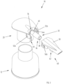
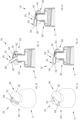
- FIG. 1 An example of embodiment of a device 10 for dispensing fluids or liquids, which is the subject of the present invention, is shown in the dispensing system 1 of Figure 1 , where the dispensing device 10 is applied to a container C holding a fluid or liquid F to be dispensed.
- dispensing device 10 is shown as a part of a dispensing system 1 according to a first preferred embodiment of the invention.
- the dispensing device according to the invention is represented as a separate part, it being clear that it must be understood as applicable to a container C.
- the container C it can be of any type, for example rigid or collapsible, in plastic or metal and/or in any shape suitable for the intended purpose.
- the device 10 comprises drawing means 20 designed to draw the fluid F from the container C through a drawing pipe and a dispensing duct 30 (better visible in Figure 6 ) designed to dispense the fluid F withdrawn from the container C.
- the drawing means 20 allow the fluid F to be dispensed by pressing the device 10 downwards.
- the fluid F is dispensed through the dispensing duct 30 and in the successive release step the device 10 returns to its initial position, as shown in Figures from 1 to 4, ready for the successive dispensing operation.
- drawing means can also be made in a manner different from that illustrated herein, according to the type of operation of the dispensing system. Some different drawing means are shown, for example, with reference to the variant embodiments described here below.
- the drawing means 20 preferably comprise connection means 12, for example a threaded ring, through which the device 10 can be connected/fixed to the container C, preferably screwed to the neck of the container C of the fluid F to be dispensed.
- connection means may not be present and the dispensing device may preferably be made in a single piece with the container, preferably in a co-moulded plastic material, or connected in such a way that it becomes integral with it, preferably through a welding operation.
- the dispensing duct 30 is defined by a tubular element 32 having a first part 34 fluidically connected to the drawing means 20 and a second part 36 provided with an outlet opening 38 for the fluid F.
- the tubular element 32 comprises at least one flexible portion 40 suited to allow the second part 36 to be arranged in a first position and in a second position, different from the first position, with respect to the first part 34.
- Figures from 1 to 6 show the device 10 with the tubular element 32 arranged in said first position corresponding to the dispensing position.
- the second position corresponds to the position in which the device 10 is positioned during the packaging step, once the container C has been filled with fluid F and prepared to be transported towards the buyer.
- the dispensing duct 30 features better water tightness at the level of the obstruction area, since there are no mechanical elements that interrupt the tubular element 32, such as hinges, for example.
- the tubular element 32 is preferably made in a single piece with the drawing means 20, more preferably by co-moulding a plastic material.
- tubular element may be made as a separate element, as can be seen for example in the embodiments shown in Figures from 29 to 45, and be successively associated with the drawing means, for example through a glueing or heat welding or ultrasound welding process or through mechanical interference.
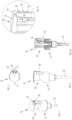
- the flexible portion 40 is obtained by partially reducing the thickness of the tubular element 32, as better highlighted in Figure 3 .
- the flexible portion can be obtained in a different manner, as shown even below with reference to Figures from 37 to 53.
- the flexible portion is obtained by changing the geometric shape of the tubular element, for example by changing its thickness, as explained above, or by shaping the same portion in a specific manner (for example, by shaping it as a bellows, as shown in Figure 49 ) or preferably by locally varying the elastic characteristic of the tubular element at the level of the flexible portion, for example through the use of different materials.
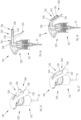
- the second part 36 of the tubular element 32 is enveloped by a spout 50, more preferably made of a rigid plastic material.
- the spout 50 is preferably hinged to the drawing means 20, substantially at the level of the flexible portion 40 of the tubular element 32.
- the spout 50 advantageously follows the tubular element 32 when it is arranged in its different positions.
- the hinged configuration of the spout 50 and the drawing means 20 guides the rotation of the tubular element 32 in its various positions.
- the device 10 comprises holding means 60 suited to hold the tubular element 32 in the second position.
- the holding means 60 comprise mechanical interference means arranged between the tubular element 32 and the drawing means 20.
- the holding means 60 preferably comprise an element 62 projecting from the underside of the spout 50 and suited to be snap-fitted into a slot 64 formed in the drawing means 20.
- the holding means 60 hold the tubular element 32 securely in said position.
- the user will need to release the spout 50 and bring the tubular element 32 to the first position, or position of use.
- the holding means may assume other shapes, some of which are shown in the embodiments described in detail here below.
- Figures from 12 to 15 show a preferred variant embodiment of the dispensing device 110 of the invention, which differs from the embodiment illustrated and described above with reference to Figures from 1 to 11 in that the spout 150 is not hinged to the drawing means 20.
- the rotation of the tubular element 132 takes place around its flexible portion 40 while the spout 150 serves the retaining function thanks to the presence of the projecting element 62.
- the tubular element 132 and the spout 150 are preferably made in a single piece, preferably in a co-moulded plastic material.
- Said second embodiment is simplified compared to the embodiment described above while at the same time offering the same advantages.
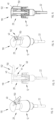
- Figures from 16 to 19 show another variant embodiment 210 of the dispensing device that is the subject of the invention.
- Said embodiment differs from the embodiments previously described first of all in that it does not have any spout encasing the tubular element 32.
- tubular element 32 receives in its end portion, in proximity to the outlet opening 38, a diffuser element 240 suited to allow the fluid F to be dispensed in the form of a spray.
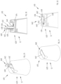
- the device 310 preferably comprises drawing means 320 designed to draw the fluid F from the container C and a dispensing duct 330 designed to dispense the fluid F withdrawn from the container C.
- the drawing means 320 make it possible to dispense the fluid F by overturning the container C in such a way as to position the dispensing duct 330 with its outlet opening 338 facing downwards.
- the fluid F flows out, preferably due to gravity, through the outlet opening 338, or even due to the pressure exerted on the container C when this is made of a collapsible material.
- the dispensing duct 330 is defined by a tubular element 332 having a first part 334 fluidically connected to the drawing means 320 and a second part 336 provided with an outlet opening 338 for the fluid F.
- the tubular element 332 comprises a flexible portion 340 suited to allow the second part 336 to be arranged in a first position and in a second position, different from the first position, with respect to the first part 334.
- Figures 20 and 21 show the device 310 with the tubular element 332 arranged in said first position, preferably corresponding to the dispensing position.
- Figures 22 and 23 instead, show the device 310 with the tubular element 332 arranged in said second position, preferably corresponding to the rest position or packaging position of the device 310.
- the overall dimensions of the tubular element 332 are smaller compared to the first dispensing position, as can be inferred, in particular, by comparing Figures 20 and 22 .
- the device 310 comprises holding means 360 suited to maintain the tubular element 332 in the second position.
- the holding means 360 comprise a closing element 362 suited to be arranged in two respective positions: an open position ( Figures 20 and 21 ) and a closed position ( Figures 22 and 23 ).
- the closing element 362 preferably slides between said two positions. More specifically, in the closed position the closing element 362 pushes against the tubular element 332, maintaining it in the second position.
- Figure 24 shows a variant embodiment 410 of the dispensing device, which differs from the embodiment shown in Figures from 20 to 23 in that in the closed position the closing element 462 of the holding means 460 is shaped in such a way as to push against the tubular element 332, so that in said second position the dispensing duct 330 is completely obstructed. This variant is not encompassed by the wording of the claims.
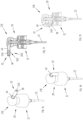
- Figures from 25 to 28 show another variant embodiment 510 of the dispensing device, this variant not being encompassed by the wording of the claims.
- the device 510 preferably comprises drawing means 520 designed to draw the fluid F from a container C (not illustrated) and a dispensing duct 530 designed to dispense the fluid F withdrawn from the container.
- the drawing means 520 comprise a lever 525 in the shape of a trigger, which is pulled in order to dispense the fluid F from the dispensing duct 530.
- the drawing means 520 preferably comprise connection means 512, for example a threaded ring, through which the device 510 can be connected/fixed to the container, preferably screwed to the neck of the container of the fluid F to be dispensed.
- connection means 512 for example a threaded ring
- the dispensing duct 530 is defined by a tubular element 532 having a first part 534 fluidically connected to the drawing means 520 and a second part 536 provided with an outlet opening 538 for the fluid F.
- the tubular element 532 comprises a flexible portion 540 suited to allow the second part 536 to be arranged in a first position and in a second position, different from the first position, with respect to the first part 534.
- Figures 25 and 26 show the device 510 with the tubular element 532 arranged in said first position, preferably corresponding to the dispensing position.
- Figures 27 and 28 instead, show the device 510 with the tubular element 532 arranged in said second position, preferably corresponding to the rest position or packaging position of the device 510.
- the flexible portion 540 in the second position partially obstructs the dispensing duct 530.
- the device 510 comprises holding means 560 suited to maintain the tubular element 532 in the second position.
- the holding means 560 are constituted by the mechanical interference of the second part 536 of the tubular element 532 that is pushed into a slot 526 formed in the lever 525.
- tubular element 532 receives in its end portion, in proximity to the outlet opening 538, a diffuser element 542 suited to allow the fluid F to be dispensed in the form of a spray.
- Figures from 29 to 32 show another variant embodiment 610 of the dispensing device, this variant not being encompassed by the wording of the claims.
- the device 610 preferably comprises drawing means 620 designed to draw the fluid F from the container C and a dispensing duct 630 designed to dispense the fluid F withdrawn from the container C.
- the drawing means 620 make it possible to dispense the fluid F by overturning the container C, in such a way as to position the dispensing duct 630 with its outlet opening 638 facing downwards.
- the fluid F flows out, preferably due to gravity, through the outlet opening 638, or even due to the pressure exerted on the container C when this is made of a collapsible material.
- the dispensing duct 630 is defined by a tubular element 632 having a first part 634 fluidically connected to the drawing means 620 and a second part 636 provided with an outlet opening 638 for the fluid F.
- the tubular element 632 comprises a flexible portion 640 suited to allow the second part 636 to be arranged in a first position and in a second position, different from the first position, with respect to the first part 634.
- Figures 29 and 30 show the device 610 with the tubular element 632 arranged in said first position, preferably corresponding to the dispensing position.
- Figures 31 and 32 instead, show the device 610 with the tubular element 632 arranged in said second position, preferably corresponding to the rest position or packaging position of the device 610, with the dispensing duct 630 completely obstructed.
- the device 610 comprises holding means 660 suited to maintain the tubular element 632 in the second position.
- the holding means 660 comprise a closing element 662 suited to be arranged in two respective positions: an open position ( Figures 29 and 30 ) and a closed position ( Figures 31 and 32 ).
- the closing element 662 preferably slides between said two positions. More specifically, in the closed position the closing element 662 snaps closed, maintaining the tubular element 632 in the second position.
- Figures from 33 to 36 show another variant embodiment 710 of the dispensing device, this variant not being encompassed by the wording of the claims.
- the device 710 preferably comprises drawing means 720 designed to draw the fluid F from the container C and a dispensing duct 730 designed to dispense the fluid F withdrawn from the container C.
- the drawing means 720 make it possible to dispense the fluid F by overturning the container C, in such a way as to position the dispensing duct 730 with its outlet opening 738 facing downwards.
- the fluid F flows out, preferably due to gravity, through the outlet opening 738, or even due to the pressure exerted on the container C when this is made of a collapsible material.
- the dispensing duct 730 is defined by a tubular element 732 having a first part 734 fluidically connected to the drawing means 720 and a second part 736 provided with an outlet opening 738 for the fluid F.
- the tubular element 732 comprises a flexible portion 740 suited to allow the second part 736 to be arranged in a first position and in a second position, different from the first position, with respect to the first part 734.
- Figures 33 and 34 show the device 710 with the tubular element 732 arranged in said first position, preferably corresponding to the dispensing position.
- Figures 35 and 36 instead, show the device 710 with the tubular element 732 arranged in said second position, preferably corresponding to the rest position or packaging position of the device 710, with the dispensing duct 730 completely obstructed.
- the device 710 comprises holding means 760 suited to maintain the tubular element 732 in the second position.
- the holding means 760 comprise a closing element 762 suited to be arranged in two respective positions: an open position ( Figures 33 and 34 ) and a closed position ( Figures 35 and 36 ).
- the closing element 762 can be rotated between said two positions. More specifically, in the closed position the closing element 762 snaps closed, maintaining the tubular element 732 in the second position.
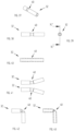
- FIGS. 37 to 43 show a possible embodiment of the tubular element 32, in which the latter is preferably carried out as a separate element to be connected to the drawing means of the device of the invention, according to the The embodiment of tubular element 32 shown in figures 37 to 43 is not encompassed by the wording of the claims.
- Said embodiment of the tubular element 32 has its flexible portion 40 obtained by changing the thickness of the tubular element 32 itself.
- the thickness reduction is substantially uniform.
- Figure 41 shows two positions that can be assumed by the tubular element 32, slightly folded and occupying less space compared to the situation illustrated in Figure 38 (dispensing position).
- Figures 42 and 43 show a totally folded position of the tubular element 32, in which it is completely obstructed.
- Figures from 44 to 48 show a variant embodiment of the tubular element 32, which differs from the embodiment of Figures from 37 to 43 due to the different shape of the flexible portion 40.
- the section with reduced thickness is curved and therefore the thickness varies accordingly.
- Figure 48 shows two positions that can be assumed by the tubular element 32, slightly folded and occupying less space compared to the situation illustrated in Figure 45 (dispensing position).
- Figures from 44 to 53 show a variant embodiment of the tubular element 32, which differs from the embodiment of Figures from 37 to 43 due to the different shape of the flexible portion 40.
- the flexible portion 40 is shaped as a bellows.
- Figure 53 shows some positions that can be assumed by the tubular element 32, slightly folded and occupying less space compared to the situation illustrated in Figure 50 .
- the present invention makes it possible to achieve the set objects and to overcome the drawbacks that are typical of the dispensing devices carried out according to the known art.
- the present invention in fact, makes it possible to avoid or at least minimize the risk of leakages of fluid or liquid, independently of the operating position of the dispensing device.
Landscapes
- Containers And Packaging Bodies Having A Special Means To Remove Contents (AREA)
Claims (11)
- Abgabevorrichtung (10, 110, 210), die dazu ausgelegt ist, ein Fluid oder eine Flüssigkeit (F), das/die in einem Behälter (C) enthalten ist, als Antwort auf ein Herabdrücken der Vorrichtung in Richtung des Behälters abzugeben, wobei die Vorrichtung (10, 110, 210) Folgendes umfasst:ein Ansaugmittel (20), das dazu ausgelegt ist, das Fluid oder die Flüssigkeit (F) aus dem Behälter (C) anzusaugen, und eine Abgabeleitung (30) für das Fluid oder die Flüssigkeit (F), wobei die Abgabeleitung (30) durch ein rohrförmiges Element (32, 132) definiert ist, welches einen ersten Abschnitt (34), der fluidisch mit dem Ansaugmittel (20) verbunden ist, und einen zweiten Abschnitt (36) aufweist, der mit einer Auslassöffnung (38) für das Fluid oder die Flüssigkeit (F) bereitgestellt ist, wobei das rohrförmige Element (32, 132) zumindest einen flexiblen Abschnitt (40) umfasst, der dazu ausgelegt ist, zu ermöglichen, dass der zweite Abschnitt (36) in Bezug auf den ersten Abschnitt (34) in einer ersten Abgabeposition und einer zweiten, sich von der Abgabeposition unterscheidenden, Ruhe-/Verpackungsposition angeordnet ist,wobei der flexible Abschnitt (40) in der zweiten Position vollständig versperrt ist;wobei der flexible Abschnitt mit einer anderen geometrischen Form relativ zur Form des ersten und des zweiten Abschnitts ausgebildet ist; undwobei der flexible Abschnitt (40) eine konkave Außenfläche aufweist, sodass das die Wanddicke des rohrförmigen Elements (32, 132) im flexiblen Abschnitt variiert.
- Abgabevorrichtung (10, 110, 210), die dazu ausgelegt ist, ein Fluid oder eine Flüssigkeit (F), das/die in einem Behälter (C) enthalten ist, als Antwort auf ein Herabdrücken der Vorrichtung in Richtung des Behälters abzugeben, wobei die Vorrichtung (10, 110, 210) Folgendes umfasst:
ein Ansaugmittel (20), das dazu ausgelegt ist, das Fluid oder die Flüssigkeit (F) aus dem Behälter (C) anzusaugen, und eine Abgabeleitung (30) für das Fluid oder die Flüssigkeit (F), wobei die Abgabeleitung (30) durch ein rohrförmiges Element (32, 132) definiert ist, welches einen ersten Abschnitt (34), der fluidisch mit dem Ansaugmittel (20) verbunden ist, und einen zweiten Abschnitt (36) aufweist, der mit einer Auslassöffnung (38) für das Fluid oder die Flüssigkeit (F) bereitgestellt ist, wobei das rohrförmige Element (32, 132) zumindest einen flexiblen Abschnitt (40) umfasst, der dazu ausgelegt ist, zu ermöglichen, dass der zweite Abschnitt (36) in Bezug auf den ersten Abschnitt (34) in einer ersten Abgabeposition und einer zweiten, sich von der ersten Abgabeposition unterscheidenden, Ruhe-/Verpackungsposition angeordnet ist,wobei der flexible Abschnitt (40) in der zweiten Position vollständig versperrt ist;wobei der flexible Abschnitt mit einer anderen geometrischen Form relativ zur Form des ersten und des zweiten Abschnitts ausgebildet ist; undwobei der flexible Abschnitt (40) ein Balgelement umfasst. - Abgabevorrichtung (10, 110, 210) nach Anspruch 1, wobei das rohrförmige Element (32, 132) eine im Wesentlichen gleichmäßige Dickenverringerung im flexiblen Abschnitt (40) aufweist.
- Abgabevorrichtung nach Anspruch 1 oder 3, wobei ein Innendurchmesser des rohrförmigen Elements (32, 132) an allen Punkten zwischen dem ersten Abschnitt und dem zweiten Abschnitt konstant ist, wenn der zweite Abschnitt sich in der ersten Position befindet.
- Abgabevorrichtung nach einem der vorangegangenen Ansprüche, wobei der zweite Abschnitt (36) durch ein Ausgusselement (50, 150) umhüllt ist.
- Abgabevorrichtung nach Anspruch 5, wobei das rohrförmige Element (32, 132) gemeinsam mit dem Ausgusselement (50, 150) als einzelnes Teil als Kunststoffmaterial geformt ist.
- Abgabevorrichtung (10, 110, 210) nach Anspruch 5, wobei das Ausgusselement (50, 150) gelenkig mit dem Ansaugmittel (20) verbunden ist, um ein Drehen des rohrförmigen Elements (32, 132) zwischen der ersten Position und der zweiten Position zu ermöglichen.
- Abgabevorrichtung (10) nach Anspruch 7, wobei das Ansaugmittel (20) Ansätze (52a, 52b) und Stifte (54a) umfasst und wobei das Ausgusselement (50) Löcher (56b) umfasst, in die die Stifte (54a) eingebracht sind.
- Abgabevorrichtung nach einem der vorangegangenen Ansprüche, dadurch gekennzeichnet, dass sie ein Haltemittel (60, 260) umfasst, welches dazu ausgelegt ist, das rohrförmige Element (32, 132) in der zweiten Position zu halten.
- Abgabevorrichtung nach Anspruch 9, dadurch gekennzeichnet, dass das Haltemittel (60, 260) eine Schnappverbindung umfasst, die zwischen einem Element (62), welches von der Unterseite des Ausgusselements (50) aus wegsteht, und einem Schlitz (64), der im Ansaugmittel (20) ausgebildet ist, angeordnet ist.
- Abgabevorrichtung (210) nach einem der vorangegangenen Ansprüche, wobei ein Zerstäubungselement (240) im rohrförmigen Element (32, 132) nahe beim Auslass (38) positioniert ist, um Fluid (F) in Sprühnebelform abzugeben.
Applications Claiming Priority (2)
| Application Number | Priority Date | Filing Date | Title |
|---|---|---|---|
| IT201800008383 | 2018-09-06 | ||
| PCT/IB2019/056677 WO2020049380A1 (en) | 2018-09-06 | 2019-08-06 | Device for dispensing fluids or liquids in general and system using this device |
Publications (2)
| Publication Number | Publication Date |
|---|---|
| EP3846943A1 EP3846943A1 (de) | 2021-07-14 |
| EP3846943B1 true EP3846943B1 (de) | 2024-11-13 |
Family
ID=64316859
Family Applications (1)
| Application Number | Title | Priority Date | Filing Date |
|---|---|---|---|
| EP19752270.9A Active EP3846943B1 (de) | 2018-09-06 | 2019-08-06 | Vorrichtung zur abgabe von fluiden oder flüssigkeiten im allgemeinen und system mit dieser vorrichtung |
Country Status (4)
| Country | Link |
|---|---|
| US (1) | US11458493B2 (de) |
| EP (1) | EP3846943B1 (de) |
| CN (1) | CN112867569B (de) |
| WO (1) | WO2020049380A1 (de) |
Citations (1)
| Publication number | Priority date | Publication date | Assignee | Title |
|---|---|---|---|---|
| WO2018104821A1 (en) * | 2016-12-06 | 2018-06-14 | Taplast S.P.A. | Dispensing device for dispensing liquids or fluids |
Family Cites Families (16)
| Publication number | Priority date | Publication date | Assignee | Title |
|---|---|---|---|---|
| US3181743A (en) | 1961-06-19 | 1965-05-04 | Sidney M Libit | Dispensing closures of the collapsible wall type |
| JPS624082A (ja) | 1985-06-20 | 1987-01-10 | 多田 哲也 | デイスペンサ |
| DE4313319B4 (de) | 1993-04-23 | 2006-09-28 | C. Ehrensperger Ag | Vorrichtung für Betätigungsvorrichtungen für Treibmitteldosen |
| US5392968A (en) * | 1993-06-14 | 1995-02-28 | Dark; Richard C. G. | Dispensing closure and method |
| US5501375A (en) | 1994-05-12 | 1996-03-26 | Cenova Innovations & Produktions Ab | Dispenser valve for dispensing a pressurized liquid |
| JP4748433B2 (ja) * | 2000-09-26 | 2011-08-17 | サーモス株式会社 | 飲料用容器の栓体 |
| DE10127895A1 (de) * | 2001-06-08 | 2002-12-12 | Indag Gmbh | Verschlusselement für eine Verpackung zur Aufnahme von flüssigem oder pastösem Gut |
| DE10255579A1 (de) | 2002-11-28 | 2004-06-09 | Wella Ag | Sprühaufsatz für ein Dosierventil eines Druckgasbehälters |
| CN101583544A (zh) * | 2007-01-16 | 2009-11-18 | 李英柱 | 具有可折叠喷嘴的抽吸装置 |
| US20090026218A1 (en) * | 2007-07-25 | 2009-01-29 | Fu Hong Industries Ltd. | Lid of beverage container |
| CN102202714A (zh) * | 2008-11-03 | 2011-09-28 | 先灵公司 | 鼻用喷射装置 |
| CN102079415B (zh) * | 2010-12-23 | 2012-09-05 | 蒋一新 | 一种吸吮饮料容器 |
| JP5354040B2 (ja) * | 2012-02-23 | 2013-11-27 | サーモス株式会社 | 飲料容器の栓体 |
| JP5831288B2 (ja) * | 2012-02-23 | 2015-12-09 | サーモス株式会社 | 飲料用容器の栓体 |
| CN102730296B (zh) * | 2012-07-09 | 2014-06-11 | 宁波爱乐宝婴儿用品有限公司 | 吸吮饮料瓶的瓶盖 |
| FR3015443B1 (fr) * | 2013-12-23 | 2016-07-01 | Lablabo | Dispositif de conditionnement et de distribution de produits fluides, liquides ou pateux |
-
2019
- 2019-08-06 EP EP19752270.9A patent/EP3846943B1/de active Active
- 2019-08-06 US US17/274,219 patent/US11458493B2/en active Active
- 2019-08-06 WO PCT/IB2019/056677 patent/WO2020049380A1/en not_active Ceased
- 2019-08-06 CN CN201980068125.9A patent/CN112867569B/zh active Active
Patent Citations (1)
| Publication number | Priority date | Publication date | Assignee | Title |
|---|---|---|---|---|
| WO2018104821A1 (en) * | 2016-12-06 | 2018-06-14 | Taplast S.P.A. | Dispensing device for dispensing liquids or fluids |
Also Published As
| Publication number | Publication date |
|---|---|
| US20210308707A1 (en) | 2021-10-07 |
| CN112867569B (zh) | 2023-08-25 |
| CN112867569A (zh) | 2021-05-28 |
| WO2020049380A1 (en) | 2020-03-12 |
| US11458493B2 (en) | 2022-10-04 |
| EP3846943A1 (de) | 2021-07-14 |
Similar Documents
| Publication | Publication Date | Title |
|---|---|---|
| RU2493075C2 (ru) | Укупорочное устройство с крышкой, уменьшающей утечку | |
| AU617029B2 (en) | A dispensing package for dispensing liquids | |
| US3430824A (en) | Liquid container with dispensing valve | |
| EP3313249B1 (de) | Spender für abgemessene dosen | |
| US9580292B2 (en) | Vented tap dispenser for liquid | |
| CN102171133A (zh) | 对来自容器的液体进行按剂量分配的方法和装置 | |
| US3409181A (en) | Squeeze bottle dispenser | |
| EA025312B1 (ru) | Выдачное устройство для выдачи пищевого продукта | |
| CN104395228B (zh) | 用于液体的排放装置 | |
| US9387965B2 (en) | One-piece squeeze-to-dose dispensing closure | |
| US5516007A (en) | Dispenser | |
| US2812113A (en) | Vented fitment | |
| US20100187195A1 (en) | Bottle With Directed Pour Spout | |
| US11052414B2 (en) | Valve for an end piece including a shut-off device | |
| EP3846943B1 (de) | Vorrichtung zur abgabe von fluiden oder flüssigkeiten im allgemeinen und system mit dieser vorrichtung | |
| US3433456A (en) | Dispenser valves | |
| CN113348038B (zh) | 测定剂量的分配器及其使用方法 | |
| JP5977642B2 (ja) | 詰替え容器用栓部材 | |
| JPH0231847A (ja) | 共用分配器 | |
| CN111670158B (zh) | 用于容器的施配封盖 | |
| JP7316633B2 (ja) | 吐出ポンプ付き液体充填容器 | |
| US2839230A (en) | Dispensing nozzle with non-drip collar | |
| EP0160139B1 (de) | Flüssigkeitsspender | |
| JP7553087B2 (ja) | パウチ容器 | |
| JP7370665B2 (ja) | 注出器 |
Legal Events
| Date | Code | Title | Description |
|---|---|---|---|
| STAA | Information on the status of an ep patent application or granted ep patent |
Free format text: STATUS: UNKNOWN |
|
| STAA | Information on the status of an ep patent application or granted ep patent |
Free format text: STATUS: THE INTERNATIONAL PUBLICATION HAS BEEN MADE |
|
| PUAI | Public reference made under article 153(3) epc to a published international application that has entered the european phase |
Free format text: ORIGINAL CODE: 0009012 |
|
| STAA | Information on the status of an ep patent application or granted ep patent |
Free format text: STATUS: REQUEST FOR EXAMINATION WAS MADE |
|
| 17P | Request for examination filed |
Effective date: 20210317 |
|
| AK | Designated contracting states |
Kind code of ref document: A1 Designated state(s): AL AT BE BG CH CY CZ DE DK EE ES FI FR GB GR HR HU IE IS IT LI LT LU LV MC MK MT NL NO PL PT RO RS SE SI SK SM TR |
|
| DAV | Request for validation of the european patent (deleted) | ||
| DAX | Request for extension of the european patent (deleted) | ||
| GRAP | Despatch of communication of intention to grant a patent |
Free format text: ORIGINAL CODE: EPIDOSNIGR1 |
|
| GRAP | Despatch of communication of intention to grant a patent |
Free format text: ORIGINAL CODE: EPIDOSNIGR1 |
|
| STAA | Information on the status of an ep patent application or granted ep patent |
Free format text: STATUS: GRANT OF PATENT IS INTENDED |
|
| INTG | Intention to grant announced |
Effective date: 20240614 |
|
| GRAS | Grant fee paid |
Free format text: ORIGINAL CODE: EPIDOSNIGR3 |
|
| GRAA | (expected) grant |
Free format text: ORIGINAL CODE: 0009210 |
|
| STAA | Information on the status of an ep patent application or granted ep patent |
Free format text: STATUS: THE PATENT HAS BEEN GRANTED |
|
| AK | Designated contracting states |
Kind code of ref document: B1 Designated state(s): AL AT BE BG CH CY CZ DE DK EE ES FI FR GB GR HR HU IE IS IT LI LT LU LV MC MK MT NL NO PL PT RO RS SE SI SK SM TR |
|
| REG | Reference to a national code |
Ref country code: GB Ref legal event code: FG4D |
|
| REG | Reference to a national code |
Ref country code: CH Ref legal event code: EP |
|
| REG | Reference to a national code |
Ref country code: DE Ref legal event code: R096 Ref document number: 602019061944 Country of ref document: DE |
|
| REG | Reference to a national code |
Ref country code: IE Ref legal event code: FG4D |
|
| P01 | Opt-out of the competence of the unified patent court (upc) registered |
Free format text: CASE NUMBER: APP_67375/2024 Effective date: 20241219 |
|
| REG | Reference to a national code |
Ref country code: LT Ref legal event code: MG9D |
|
| REG | Reference to a national code |
Ref country code: NL Ref legal event code: MP Effective date: 20241113 |
|
| PG25 | Lapsed in a contracting state [announced via postgrant information from national office to epo] |
Ref country code: IS Free format text: LAPSE BECAUSE OF FAILURE TO SUBMIT A TRANSLATION OF THE DESCRIPTION OR TO PAY THE FEE WITHIN THE PRESCRIBED TIME-LIMIT Effective date: 20250313 Ref country code: HR Free format text: LAPSE BECAUSE OF FAILURE TO SUBMIT A TRANSLATION OF THE DESCRIPTION OR TO PAY THE FEE WITHIN THE PRESCRIBED TIME-LIMIT Effective date: 20241113 Ref country code: PT Free format text: LAPSE BECAUSE OF FAILURE TO SUBMIT A TRANSLATION OF THE DESCRIPTION OR TO PAY THE FEE WITHIN THE PRESCRIBED TIME-LIMIT Effective date: 20250313 |
|
| PG25 | Lapsed in a contracting state [announced via postgrant information from national office to epo] |
Ref country code: FI Free format text: LAPSE BECAUSE OF FAILURE TO SUBMIT A TRANSLATION OF THE DESCRIPTION OR TO PAY THE FEE WITHIN THE PRESCRIBED TIME-LIMIT Effective date: 20241113 Ref country code: NL Free format text: LAPSE BECAUSE OF FAILURE TO SUBMIT A TRANSLATION OF THE DESCRIPTION OR TO PAY THE FEE WITHIN THE PRESCRIBED TIME-LIMIT Effective date: 20241113 |
|
| REG | Reference to a national code |
Ref country code: AT Ref legal event code: MK05 Ref document number: 1741284 Country of ref document: AT Kind code of ref document: T Effective date: 20241113 |
|
| PG25 | Lapsed in a contracting state [announced via postgrant information from national office to epo] |
Ref country code: BG Free format text: LAPSE BECAUSE OF FAILURE TO SUBMIT A TRANSLATION OF THE DESCRIPTION OR TO PAY THE FEE WITHIN THE PRESCRIBED TIME-LIMIT Effective date: 20241113 |
|
| PG25 | Lapsed in a contracting state [announced via postgrant information from national office to epo] |
Ref country code: ES Free format text: LAPSE BECAUSE OF FAILURE TO SUBMIT A TRANSLATION OF THE DESCRIPTION OR TO PAY THE FEE WITHIN THE PRESCRIBED TIME-LIMIT Effective date: 20241113 |
|
| PG25 | Lapsed in a contracting state [announced via postgrant information from national office to epo] |
Ref country code: NO Free format text: LAPSE BECAUSE OF FAILURE TO SUBMIT A TRANSLATION OF THE DESCRIPTION OR TO PAY THE FEE WITHIN THE PRESCRIBED TIME-LIMIT Effective date: 20250213 |
|
| PG25 | Lapsed in a contracting state [announced via postgrant information from national office to epo] |
Ref country code: GR Free format text: LAPSE BECAUSE OF FAILURE TO SUBMIT A TRANSLATION OF THE DESCRIPTION OR TO PAY THE FEE WITHIN THE PRESCRIBED TIME-LIMIT Effective date: 20250214 Ref country code: LV Free format text: LAPSE BECAUSE OF FAILURE TO SUBMIT A TRANSLATION OF THE DESCRIPTION OR TO PAY THE FEE WITHIN THE PRESCRIBED TIME-LIMIT Effective date: 20241113 Ref country code: AT Free format text: LAPSE BECAUSE OF FAILURE TO SUBMIT A TRANSLATION OF THE DESCRIPTION OR TO PAY THE FEE WITHIN THE PRESCRIBED TIME-LIMIT Effective date: 20241113 |
|
| PG25 | Lapsed in a contracting state [announced via postgrant information from national office to epo] |
Ref country code: PL Free format text: LAPSE BECAUSE OF FAILURE TO SUBMIT A TRANSLATION OF THE DESCRIPTION OR TO PAY THE FEE WITHIN THE PRESCRIBED TIME-LIMIT Effective date: 20241113 |
|
| PG25 | Lapsed in a contracting state [announced via postgrant information from national office to epo] |
Ref country code: RS Free format text: LAPSE BECAUSE OF FAILURE TO SUBMIT A TRANSLATION OF THE DESCRIPTION OR TO PAY THE FEE WITHIN THE PRESCRIBED TIME-LIMIT Effective date: 20250213 |
|
| PG25 | Lapsed in a contracting state [announced via postgrant information from national office to epo] |
Ref country code: SM Free format text: LAPSE BECAUSE OF FAILURE TO SUBMIT A TRANSLATION OF THE DESCRIPTION OR TO PAY THE FEE WITHIN THE PRESCRIBED TIME-LIMIT Effective date: 20241113 |
|
| PG25 | Lapsed in a contracting state [announced via postgrant information from national office to epo] |
Ref country code: DK Free format text: LAPSE BECAUSE OF FAILURE TO SUBMIT A TRANSLATION OF THE DESCRIPTION OR TO PAY THE FEE WITHIN THE PRESCRIBED TIME-LIMIT Effective date: 20241113 |
|
| PG25 | Lapsed in a contracting state [announced via postgrant information from national office to epo] |
Ref country code: EE Free format text: LAPSE BECAUSE OF FAILURE TO SUBMIT A TRANSLATION OF THE DESCRIPTION OR TO PAY THE FEE WITHIN THE PRESCRIBED TIME-LIMIT Effective date: 20241113 |
|
| PG25 | Lapsed in a contracting state [announced via postgrant information from national office to epo] |
Ref country code: RO Free format text: LAPSE BECAUSE OF FAILURE TO SUBMIT A TRANSLATION OF THE DESCRIPTION OR TO PAY THE FEE WITHIN THE PRESCRIBED TIME-LIMIT Effective date: 20241113 |
|
| PG25 | Lapsed in a contracting state [announced via postgrant information from national office to epo] |
Ref country code: SK Free format text: LAPSE BECAUSE OF FAILURE TO SUBMIT A TRANSLATION OF THE DESCRIPTION OR TO PAY THE FEE WITHIN THE PRESCRIBED TIME-LIMIT Effective date: 20241113 |
|
| PG25 | Lapsed in a contracting state [announced via postgrant information from national office to epo] |
Ref country code: CZ Free format text: LAPSE BECAUSE OF FAILURE TO SUBMIT A TRANSLATION OF THE DESCRIPTION OR TO PAY THE FEE WITHIN THE PRESCRIBED TIME-LIMIT Effective date: 20241113 |
|
| REG | Reference to a national code |
Ref country code: DE Ref legal event code: R097 Ref document number: 602019061944 Country of ref document: DE |
|
| PG25 | Lapsed in a contracting state [announced via postgrant information from national office to epo] |
Ref country code: SE Free format text: LAPSE BECAUSE OF FAILURE TO SUBMIT A TRANSLATION OF THE DESCRIPTION OR TO PAY THE FEE WITHIN THE PRESCRIBED TIME-LIMIT Effective date: 20241113 |
|
| PLBE | No opposition filed within time limit |
Free format text: ORIGINAL CODE: 0009261 |
|
| STAA | Information on the status of an ep patent application or granted ep patent |
Free format text: STATUS: NO OPPOSITION FILED WITHIN TIME LIMIT |
|
| PGFP | Annual fee paid to national office [announced via postgrant information from national office to epo] |
Ref country code: DE Payment date: 20250827 Year of fee payment: 7 |
|
| PGFP | Annual fee paid to national office [announced via postgrant information from national office to epo] |
Ref country code: IT Payment date: 20250820 Year of fee payment: 7 |
|
| PGFP | Annual fee paid to national office [announced via postgrant information from national office to epo] |
Ref country code: GB Payment date: 20250827 Year of fee payment: 7 |
|
| PGFP | Annual fee paid to national office [announced via postgrant information from national office to epo] |
Ref country code: FR Payment date: 20250825 Year of fee payment: 7 |
|
| 26N | No opposition filed |
Effective date: 20250814 |
|
| REG | Reference to a national code |
Ref country code: CH Ref legal event code: H13 Free format text: ST27 STATUS EVENT CODE: U-0-0-H10-H13 (AS PROVIDED BY THE NATIONAL OFFICE) Effective date: 20260324 |
|
| PG25 | Lapsed in a contracting state [announced via postgrant information from national office to epo] |
Ref country code: MC Free format text: LAPSE BECAUSE OF FAILURE TO SUBMIT A TRANSLATION OF THE DESCRIPTION OR TO PAY THE FEE WITHIN THE PRESCRIBED TIME-LIMIT Effective date: 20241113 |
|
| PG25 | Lapsed in a contracting state [announced via postgrant information from national office to epo] |
Ref country code: LU Free format text: LAPSE BECAUSE OF NON-PAYMENT OF DUE FEES Effective date: 20250806 |