EP3844094B1 - Distributeur de dosage - Google Patents
Distributeur de dosage Download PDFInfo
- Publication number
- EP3844094B1 EP3844094B1 EP19756340.6A EP19756340A EP3844094B1 EP 3844094 B1 EP3844094 B1 EP 3844094B1 EP 19756340 A EP19756340 A EP 19756340A EP 3844094 B1 EP3844094 B1 EP 3844094B1
- Authority
- EP
- European Patent Office
- Prior art keywords
- wall
- housing
- space
- containing space
- bag
- Prior art date
- Legal status (The legal status is an assumption and is not a legal conclusion. Google has not performed a legal analysis and makes no representation as to the accuracy of the status listed.)
- Active
Links
Images






Classifications
-
- B—PERFORMING OPERATIONS; TRANSPORTING
- B67—OPENING, CLOSING OR CLEANING BOTTLES, JARS OR SIMILAR CONTAINERS; LIQUID HANDLING
- B67D—DISPENSING, DELIVERING OR TRANSFERRING LIQUIDS, NOT OTHERWISE PROVIDED FOR
- B67D7/00—Apparatus or devices for transferring liquids from bulk storage containers or reservoirs into vehicles or into portable containers, e.g. for retail sale purposes
- B67D7/02—Apparatus or devices for transferring liquids from bulk storage containers or reservoirs into vehicles or into portable containers, e.g. for retail sale purposes for transferring liquids other than fuel or lubricants
- B67D7/0216—Apparatus or devices for transferring liquids from bulk storage containers or reservoirs into vehicles or into portable containers, e.g. for retail sale purposes for transferring liquids other than fuel or lubricants by squeezing collapsible or flexible storage containers
-
- B—PERFORMING OPERATIONS; TRANSPORTING
- B67—OPENING, CLOSING OR CLEANING BOTTLES, JARS OR SIMILAR CONTAINERS; LIQUID HANDLING
- B67D—DISPENSING, DELIVERING OR TRANSFERRING LIQUIDS, NOT OTHERWISE PROVIDED FOR
- B67D1/00—Apparatus or devices for dispensing beverages on draught
- B67D1/0001—Apparatus or devices for dispensing beverages on draught by squeezing collapsible or flexible storage containers
-
- B—PERFORMING OPERATIONS; TRANSPORTING
- B67—OPENING, CLOSING OR CLEANING BOTTLES, JARS OR SIMILAR CONTAINERS; LIQUID HANDLING
- B67D—DISPENSING, DELIVERING OR TRANSFERRING LIQUIDS, NOT OTHERWISE PROVIDED FOR
- B67D1/00—Apparatus or devices for dispensing beverages on draught
- B67D1/04—Apparatus utilising compressed air or other gas acting directly or indirectly on beverages in storage containers
- B67D1/0462—Squeezing collapsible or flexible beverage containers, e.g. bag-in-box containers
-
- G—PHYSICS
- G01—MEASURING; TESTING
- G01F—MEASURING VOLUME, VOLUME FLOW, MASS FLOW OR LIQUID LEVEL; METERING BY VOLUME
- G01F13/00—Apparatus for measuring by volume and delivering fluids or fluent solid materials, not provided for in the preceding groups
-
- B—PERFORMING OPERATIONS; TRANSPORTING
- B67—OPENING, CLOSING OR CLEANING BOTTLES, JARS OR SIMILAR CONTAINERS; LIQUID HANDLING
- B67D—DISPENSING, DELIVERING OR TRANSFERRING LIQUIDS, NOT OTHERWISE PROVIDED FOR
- B67D2210/00—Indexing scheme relating to aspects and details of apparatus or devices for dispensing beverages on draught or for controlling flow of liquids under gravity from storage containers for dispensing purposes
- B67D2210/0016—Adapted for dispensing high viscosity products
Definitions
- the invention relates to a dosing dispenser for viscous products. Using the dosing dispenser, small amounts of viscous product can be dispensed without packaging.
- viscous products such as quark or jam are usually sold to the customer in small containers and individually packaged. This causes a relatively large amount of packaging waste.
- care products or medical products such. B. cream and ointments, kept in small containers. This also causes a corresponding amount of packaging waste.
- the object of the present invention is to specify a dosing dispenser which, with simple production and low-maintenance operation, enables viscous products to be dispensed in a user-friendly manner.
- the dosing dispenser should also enable temperature control of the product.
- the object is achieved by a dosing dispenser that is designed in particular for use z. B. in retail, in regional direct sales, in gastronomy, in wholesale, in pharmacies, in surgeries, in care facilities, in hospitals, etc.
- the dosing dispenser includes a housing. At least one receiving space is formed in the housing. In particular, exactly one receiving space is provided or two or three or four receiving spaces are provided.
- the respective receiving space is designed to receive at least one bag.
- bags are used that are filled with the viscous product.
- bag describes any desired, preferably flexible, packaging of the product.
- Packaging means in particular the "primary packaging”.
- the dosing dispenser includes a plunger per receiving space, the plunger being arranged in the receiving space and used to squeeze out the at least one bag.
- the outer diameter of the plunger essentially corresponds to the inner diameter of the receiving space, so that the plunger presses onto the bag over the full surface of the receiving space and thus the full surface of the bag.
- the dosing dispenser includes an actuating device, guided or supported in the housing, for each plunger for actuating the respective plunger in a linearly movable manner.
- the corresponding stamp can be moved along a stamp axis in the receiving space via this actuating device, so that the bag can be squeezed out by means of the stamp.
- An outlet opening for the product is located in the area of one end (first end) of the respective receiving space.
- the product leaves the housing and thus the dosing dispenser via this outlet opening.
- the outlet opening is arranged on the bottom.
- the outlet opening is in the area of the first end, but on the side of the dosing dispenser. As a result, the product is dispensed on the side of the housing.
- the bag By using the bag, there is no contact between the viscous product and the dispenser while the dispenser is in use. As a result, the cleaning of the dosing dispenser is extremely easy or not necessary, since the squeezed-out bag can be easily removed from the receiving space and a new bag can be inserted.
- the outlet opening is designed and arranged in such a way that one end of the bag can protrude out of the receiving opening, for example into a dispensing space under the housing, so that there is no contact between the dosing dispenser and the product in this area either.
- the dosing dispenser therefore does not require any pumps, hoses or other devices for conveying the viscous product.
- the dimensions of the dosing dispenser are designed in particular for the above-mentioned areas of application.
- the individual recording space includes a
- the capacity is preferably at least 0.5 liters, particularly preferably at least 1 liter.
- Such dosing dispensers are shown, for example, in the following publications: DEU 200 01 409, U.S. 5,553,740 , US2014/263440 , WO 2008/079089 .
- the receiving space has a second end opposite the first end.
- the receiving space is preferably open over its entire cross section.
- the plunger can be inserted into the receiving space at the second end.
- the housing preferably comprises a cover, so that the upper side of the housing can be opened.
- the wall of the receiving space has a refill opening. This will be described in detail later.
- the respective receiving space is formed by a cylindrical receiving space wall and at the first end by a bag support floor, which represents the support area for the bag.
- the first end of the receiving space is directly adjacent to an outer wall of the housing.
- this is a bottom outer wall of the housing.
- the bottom outer wall of the housing forms the "bag support base" defined above.
- This variant is particularly suitable for a one-piece production, in particular additive production, of the bottom outer wall with the receiving space wall.
- the receiving space is formed by a cylindrical receiving space wall and a receiving space floor at the first end.
- the receiving space's own receiving space floor forms the "bag support floor".
- the outlet opening is formed in the base of the receiving space, with the structure made up of the wall of the receiving space and the floor of the receiving space being inserted in a recess in the outer wall, preferably the outer wall of the housing.
- the diameter of the recess corresponds in particular to an outer diameter of the wall of the receiving space.
- the receiving space is in particular designed concentrically around the punch axis, with the punch axis preferably being vertical.
- the outer wall of the housing in particular the bottom outer wall (bag support floor) of the housing, or the receiving space floor (bag support floor) closes off the receiving space at its first end. Because the first end of the receiving space is directly adjacent to the outside of the housing, it is possible for the bag to protrude with its outlet area through the outlet opening to the outside, for example into a dispensing space in the stand. There is therefore no need for hoses or other guides for the product within the housing, but the bag can project outwards directly through the outlet opening. No further guidance of the product is required outside of the housing either, since a corresponding container for receiving the dispensed product can be placed directly on or under the outlet area of the bag.
- the “outer wall of the housing” is outside the receiving space.
- the “outer wall of the housing” also forms the outermost wall of the housing; alternatively, the housing can have an additional wall located further outwards.
- the stand which can optionally include its own stand side wall and/or its own stand base, is preferably connected underneath the bottom outer wall of the housing.
- the outer wall (particularly the bottom outer wall) of the housing or the receiving space floor forms the bag support floor, in particular the support area on which the bag rests directly or indirectly.
- a bottom area of an inlay can optionally be arranged between the bag and the bottom of the bag. The stamp presses the bag against this support area.
- the support area is preferably slightly conical or funnel-shaped.
- the side of the plunger pointing to the support area can also have a corresponding conical shape, so that complete emptying of the bag is supported by the complementary shapes.
- the support area and thus the bag support base are designed conically in such a way that it is lower radially on the outside than radially on the inside. As a result, condensed water flows radially outwards.
- the bag support floor preferably comprises at least one condensation water drainage opening, and preferably also a condensation water collection channel.
- the condensate collection channel is in particular a channel on the radially outer circumference of the bag support base.
- the condensed water collection channel is preferably inclined towards the at least one condensed water drain opening.
- a plurality of extensions, in particular nubs, are preferably formed on the bottom of the bag to space the bag from its supporting surface. This avoids the bag standing in the condensation water or the condensation water not being able to drain off because the bag is lying on it.
- the bag support base preferably comprises an annular outer area and a valve support area that is lower than the outer area.
- the valve of the bag or an area of the bag close to the valve can rest on the valve support area and/or be arranged in the area of the valve support area.
- the valve support area is formed in particular around the outlet opening.
- the outer area and/or the valve support area can each have at least one condensate drainage opening and/or condensate collection channel and/or extensions (e.g. knobs). In both areas, the condensed water collection channel is preferably inclined towards the at least one condensed water drain opening.
- the dosing dispenser includes the stand already mentioned, on which the housing stands.
- the stand can be made in one piece with at least part of the housing.
- the stand can also be a separate component on which the housing sits.
- the stand is designed in such a way that a container for receiving the product can be placed directly under the outlet opening(s). The user can thus place the container directly under the outlet opening(s) and actuate the at least one stamp via the actuating device. This forces the product down and flows into the container.
- a scale can be placed inside the stand and thus directly under the housing. The vessel then stands on the scales while it is being filled.
- the stand fulfills a hygienic function, since it protects the end of the bag protruding from the housing (in particular the valve) from external contamination.
- the stand to form a closed delivery space with a stand side wall and preferably a stand base.
- the delivery space is "closed” in particular for the purpose of thermal insulation.
- the stand side wall completely surrounds the closed dispensing space with the exception of a stand opening cut out in the stand side wall for inserting the container, a stand cover preferably being arranged at the stand opening for closing the stand opening.
- the stand cover is preferably arranged to be displaceable or pivotable.
- thermocontrol unit stands for a cooling unit or a heating unit or a combined unit for optional cooling and heating.
- the respective temperature control unit includes one or more Peltier elements and the associated cooler for water or air cooling of the Peltier element or Peltier elements.
- the temperature control units described here preferably each comprise at least one Peltier element. Furthermore, it is preferably provided that the respective temperature control unit (designed as a cooling unit) is equipped with a device for air cooling of the Peltier element or for water cooling of the Peltier element for dissipating the heat into the environment.
- the transfer of the cooling or heating capacity to the receiving space or delivery space takes place either by fluidless transmission and accordingly as direct as possible arrangement of the unit in the corresponding space, or by a heat transfer fluid in a corresponding fluid circuit.
- At least one column temperature control unit is therefore preferably provided for actively controlling the temperature of the delivery space, with the column temperature control unit preferably being arranged on the side wall of the column.
- the at least one column temperature control unit for the fluidless transfer of cooling or heating output is preferably arranged directly on the outside of the delivery space.
- a fluid circuit for a heat transfer fluid is provided for tempering the dispensing space, with the at least one stand temperature control unit, in particular with its Peltier element, being arranged for tempering the heat transfer fluid.
- the receiving space is formed by a cylindrical receiving space wall.
- the cross-sectional shape of the receiving space can be arbitrary, but is preferably round or oval.
- the recording space, formed by the Recording space wall is particularly open at the top (at the second end).
- the receiving space is delimited on the underside by the bag support floor, preferably formed by the outer wall (in particular bottom-outer wall) of the housing or the receiving space floor.
- the wall of the receiving space includes a refill opening and a cover that closes the refill opening.
- the refill opening or the cover is preferably located on the side of the receiving space and thus in the receiving space wall.
- the cover can be connected to the receiving space wall in particular via a hinge.
- the receiving space wall together with the bag support base ie the entire receiving space
- the receiving space wall and the bag support base are firmly connected to a housing cover in the side outer wall of the housing or are manufactured integrally. This entire unit can be removed from the housing, in particular pivoted out.
- a free space is formed between the wall of the receiving space and an outer wall (particularly the outer side wall) of the housing.
- the free space can either extend completely around the entire circumference, possibly with the exception of at least one unit space, of the receiving space wall and/or along the entire height of the receiving space wall.
- the free space is designed as a cavity between a double wall.
- the double wall is particularly preferably formed on the inside by the wall of the receiving space and/or on the outside by the side wall of the housing.
- the cavity is used for thermal insulation and is preferably filled with thermally insulating material.
- the dosing dispenser preferably comprises at least one receiving space temperature control unit, which is arranged in particular radially outside the receiving space wall. Two, three or four receiving space temperature control units are preferably provided.
- the stand temperature control unit is preferably only arranged for temperature control of the delivery space.
- at least one of the temperature control units described here (stand temperature control unit or receiving space temperature control unit) be used for the joint temperature control of the delivery room and the receiving room.
- a unit space to be formed in the housing, which is preferably delimited radially on the inside by the wall of the receiving space and is preferably open radially on the outside, with the receiving space temperature control unit being arranged completely or partially in the unit space.
- one unit space is formed for each receiving space temperature control unit.
- a thermally insulating material is used in the unit space, preferably all around the temperature control unit.
- the inlay is preferably made of aluminum.
- the inlay is preferably inherently stable, in particular with a wall thickness of at least 1 mm.
- the tube area of the inlay preferably extends over at least 50% of the height of the receiving space.
- a recess aligned with the outlet opening is preferably provided in the bottom area.
- the base area includes condensation water recesses for conducting the condensation water down to the bag support base, the bag not lying directly on the bag support base of the receiving space, but on the base area of the inlay. Provision is also preferably made for the bottom area to have extensions, in particular nubs, for spacing the bag.
- a fluid circuit for a heat transfer fluid is provided for tempering the receiving space, with the at least one receiving space temperature control unit, in particular with its Peltier element, being arranged for cooling the heat transfer fluid.
- the free space may extend only over part of the circumference and/or part of the height of the wall of the receiving space. This is the case in particular if the receiving space wall borders in sections on a partition in the housing or on the outer side wall of the housing or on a receiving space wall of a further receiving space or in sections through this partition and/or outer side wall and/or further receiving space wall is formed.
- a thermally insulating material is preferably arranged in the free space, in particular in the form of a hollow space.
- the exterior wall and/or the exterior wall of the housing (bottom exterior wall and/or side exterior wall) comprises cavities for thermal insulation.
- the free space can be used for further components of the dosing dispenser. It is preferably provided that components of an active temperature control (for cooling or heating) are arranged in the free space. These components of the active temperature control include, for example, channels for guiding a heat transfer fluid and/or electrothermal components, such as Peltier elements, for temperature control. Furthermore, sensors can also be arranged in the free space. Exemplary sensors will be described in detail later.
- the dosing dispenser includes an actuating device for moving the respective plunger.
- This actuating device preferably comprises a transmission device per stamp and at least one drive device.
- the drive device is designed to move the transmission device(s).
- the respective transfer device in turn moves the stamp.
- the several transmission devices can each be moved with their own drive device.
- a transmission device is provided, the torque of a Transmission device transmits to at least one further transmission device, whereby at least two stamps can be moved with only one drive device.
- the respective transmission device is preferably guided in the housing.
- One end of the transfer device is connected to the stamp.
- the other end of the transmission device is connected to the driving device; or the transmission device is coupled to another transmission device via the transmission device.
- the transfer device is preferably a spindle.
- the spindle is guided in an internal thread fixed to the housing. This internal thread guides the spindle and at the same time supports the spindle in relation to the housing.
- connection between the spindle and the ram is preferably not torque-transmitting, so that the ram does not rotate together with the spindle but only moves linearly along the ram axis. This avoids that the bag is loaded with torque.
- the drive device and the transmission device can be configured in any way.
- the actuating device can also be a rod that can be moved linearly in the housing and that is moved, for example, via a drive device designed as a lever. This lever is supported on the housing.
- the drive device is preferably designed for manual operation.
- the drive device includes in particular a crank or a wheel, for example to turn the spindle described above.
- a 90° deflection gear is preferably arranged between the rotatable drive device and the transmission device.
- the axis of rotation of the crank or wheel is therefore perpendicular to the axis of the punch or spindle.
- the internal thread can preferably be divided non-destructively for removal and/or quick adjustment of the spindle.
- the internal thread comprises at least two internal thread parts which can be moved apart perpendicularly to the punch axis.
- Two opposing thread carriers are preferably arranged in the support area.
- An internally threaded portion is fastened or integrally formed on each thread carrier.
- the threaded carriers are accommodated in the support area so that they can move perpendicularly to the punch axis, for example so that they can move linearly or in rotation.
- the threaded carriers are preferably secured by means of a stop against being completely pulled out or pivoted out of the support area.
- the threaded carriers are preferably fixed in position with a movable securing element in relation to the support area, in particular the housing.
- the securing elements can preferably be detached without tools.
- the drive device for manual operation comprises a lever, for example.
- the drive device can also have an electric motor for driving the transmission device.
- Manual operation is preferred, however, since this results in a simple and low-maintenance design of the dosing dispenser.
- the housing preferably includes a support area.
- the transmission device is guided and/or supported on the support area.
- the drive device can also be supported on the support area. This is the case, for example, when the drive device is designed as a lever and the lever is supported on the housing, namely the support area.
- the receptacle of the internal thread in the housing serves as a support area, since both the guidance and the support of the transmission device, namely the spindle, take place via the internal thread.
- the housing also includes the support area, which has already been described.
- the support area is in particular the bottom outer wall of the housing at the first end of the receiving space or the receiving space floor. The bag rests on the support area.
- a technical space is preferably formed in the housing. This technical space is delimited in particular by a partition within the housing. At least one electrical and/or electronic component of the dosing dispenser is located in the technical room.
- the technical room can be integrated elsewhere, for example in a floor slab.
- the technical space can be opened from the outside, for example via a cover in the side outer wall of the housing.
- the technical space is preferably sealed off in a liquid-tight manner from the rest of the housing via the partition wall.
- the partition also seals the rest of the housing from the technical room, so that no dirt from the technical room can penetrate the rest of the housing.
- active temperature control can be used. If the receiving space is tempered with a heat transfer fluid, for example, then the associated compressor and the corresponding control system are preferably located in the technology room.
- a data interface for wired and/or wireless data transmission is arranged in the technical room. Information from sensors of the dosing dispenser, for example, can be forwarded via this data interface.
- control unit is arranged in the technology room, which control unit can record and/or evaluate data from the sensors.
- the dosing dispenser preferably includes at least one quality sensor.
- the quality sensor is designed in particular to detect a temperature or other properties of the product.
- the temperature of the product can be recorded indirectly, for example on the inside or outside of the wall of the receiving space.
- the quality sensor for detecting the temperature is located on the inside of the wall of the receiving space or on the contact area of the bag, so that the temperature on the outside of the bag can be detected directly.
- a quality sensor for detecting the temperature is preferably arranged on the underside of the stamp and/or on the outlet opening.
- the quality sensor is designed as an optical sensor and can thus emit a light through the transparent bag onto the product.
- the sensor detects the reflection of the light and, based on this reflection, can conclude the quality status of the product, e.g. B. for water or serum permeability (phase separation), color change, change in optical density, etc.
- An optical quality sensor is preferably arranged at the outlet opening for detecting contamination.
- the dosing dispenser preferably includes a distance sensor which is arranged to detect a distance between the plunger and a fixed point in the dosing dispenser. For example, the filling quantity can be estimated from the recorded distance.
- the distance sensor preferably measures the distance optically, in particular by means of an infrared light source, or by means of ultrasound.
- At least one housing wall, in particular the outer side wall, of the dosing dispenser is particularly preferably manufactured in at least two individual parts using an additive manufacturing process, with the two individual parts preferably being connected by means of a tongue and groove connection.
- the groove and/or the tongue is an integral, additively manufactured part of the respective individual part.
- the individual parts are preferably each ring-shaped, in particular closed ring-shaped, with the parting plane and thus tongue and groove running perpendicular to the punch axis; or segment-shaped, with the parting plane and thus tongue and groove running parallel to the punch axis.
- the wall of the receiving space of the dosing dispenser is particularly preferably manufactured in at least two individual parts using an additive manufacturing process, with the two individual parts preferably being connected by means of a tongue and groove connection.
- the groove and/or the tongue is an integral, additively manufactured part of the respective individual part.
- the individual parts are preferably each ring-shaped, in particular closed ring-shaped, with the parting plane and thus tongue and groove running perpendicular to the punch axis; or Segment-shaped, with the parting plane and thus tongue and groove running parallel to the punch axis.
- a single part can also form part of the side outer wall and part of the receiving space wall.
- the housing in particular the outside of the housing, is preferably designed in such a way that the user recognizes the type of viscous product, regardless of any illiteracy or language barriers.
- by using additive manufacturing to manufacture the housing it is possible to produce relatively small quantities of different sizes and designs in order to create an individual housing for each product.
- the housing has a shape, in particular also color and/or graphic design, which indicates the origin and/or manufacture of the viscous product.
- the housing has the shape of a milk can, a cheese loaf, a piece of a cheese loaf, a beehive, a honeycomb or a milk-producing mammal (for example cow, goat or sheep).
- the milk jug is characterized in particular by a lower cylindrical section and an upper cylindrical section of the housing, the two cylindrical sections being connected by a conical section of the housing and the upper cylindrical section having a smaller diameter than the lower cylindrical section.
- the housing in the form of a cheese loaf is characterized in particular by its cylindrical configuration, the diameter being significantly larger than the height. If designed as a "piece of cheese wheel" the housing would correspond in its outer shape to a segment of the cheese wheel.
- the characteristic shape of the housing as a "beehive" is in particular dome-shaped on the top and possibly cylindrical in the lower area.
- the housing has a shape, in particular also color and/or graphic design, which indicates the viscous product itself or a component of the viscous product.
- the housing can be designed in the form of the corresponding fruit or the corresponding vegetable.
- the invention further encompasses a dosing dispenser assembly with a filled pouch.
- the bag includes in particular a valve, in particular designed as a membrane valve or pinch valve.
- the bag is in particular made of plastic.
- the viscous product as already described, is located in the bag.
- a dosing dispenser 1 is described in detail below with reference to the figures.
- figure 1 shows a section A: A whose cutting plane is in figure 2 is marked.
- the dosing dispenser 1 comprises a housing 2 .
- the housing 2 has a bottom outer wall 3 and a cylindrical side outer wall 4 . Furthermore, in the housing 2 there is a support area 5 and a receiving area, formed by a bag support base 6 .
- the housing 2 Inside, the housing 2 includes a partition wall 7 for separating a technical room 8.
- a receiving space 10 is formed in the housing 2 .
- the receiving space 10 is delimited by a cylindrical receiving space wall 9.
- the receiving space 10 has a first end 11 at the bottom and a second end 12 at the top.
- the upper second end 12 is open over the full circumference of the receiving space 10 .
- the first end 11 of the receiving space 10 is delimited by an area of the bottom outer wall 3 .
- This area of the bottom outer wall 3 also forms the support area 6.
- the support area 6 is conical or funnel-shaped.
- annular free space 14 which, as already described, can be used, for example, for temperature control and/or insulation.
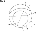
- FIG 4 shows purely schematically a receiving space diameter 15 and a housing diameter 16 .
- the housing diameter 16 is at most three times, preferably at most twice, the receiving space diameter 15 .
- the diameters and heights are designed accordingly, so that the receiving volume of the receiving space 10 is designed for the described area of use, as described in the introductory part.
- the dosing dispenser 1 also includes a plunger 20 .
- the plunger 20 is arranged in the receiving space 10 .
- An outer diameter of the stamp 20 essentially corresponds to an inner diameter of the receiving space 10.
- the stamp 20 can be moved linearly within the receiving space 10 along the stamp axis 24 shown.
- the dosing dispenser 1 also includes an actuating device 21.
- the actuating device 21 includes a transmission device 22, designed here as a spindle, and a drive device 23, designed here as a crank.
- the transmission device 22 is guided and supported in an internal thread. This internal thread is located in the support area 5 of the housing.
- the drive device 23 is designed here exclusively for manual operation.
- the lower end of the transmission device 22 is rotatably connected to the ram 20 so that the torque is not transmitted to the ram 20 .
- the metering dispenser 1 may include a stand 40 so that the housing 2 is spaced from a footprint. This makes it possible to place a container 41 under the housing 2 for receiving the viscous product.
- figure 1 shows purely schematically that a bag 42 with the viscous product can be arranged in the receiving space 10 .
- the bag 42 protrudes in particular with its valve 43 from the outlet opening 13 to the outside.
- the state shown is that the plunger 20 is in its lowest position and the bag 42 is already emptied.
- the design of the valve 43 ensures hygienic requirements, in particular the separation of the interior of the bag 42 from the external environment in those periods when no filling operations are active.
- FIG figure 1 Purely schematically shows figure 1 the arrangement of a control device 30 in the technical room 8. Furthermore, FIG figure 1 purely schematically the arrangement of at least one quality sensor 31 in the receiving space wall 9 and a position sensor 32.
- the position sensor 32 is located in particular in the lower area of the receiving space 10, so that it can detect when the plunger 20 is down and the bag 42 is empty.
- the technical room 8 can be used for various other electrical and/or electronic components.
- the technical space 8 is sealed here in a liquid-tight manner with respect to the remaining interior of the housing 2 via the partition wall 7 . Any passages for sensors and/or cables are also sealed accordingly.
- FIG. 3 shows that part of the side outer wall 4 of the housing 2 is connected to the rest of the housing 2 via a hinge. As a result, this area of the lateral outer wall 4 can be opened, as a result of which the interior of the housing 2 is accessible.
- This opening or separating plane of the housing is only shown here as an example. Alternatively, it is in particular also possible to open the housing 2 from above.
- the receiving space 10 is accessible by opening the lateral outer wall 4 .
- the receiving space wall 9 can have a corresponding refill opening.
- the second end 12 on the upper side of the receiving space 10 can also be used to remove the plunger 20 and/or to insert the bag 42 . "Refill" means that the empty bag 42 is removed and a full bag 42 is inserted.
- the receiving space wall 9 it is also possible for a part of the receiving space wall 9 to be formed by the outer side wall 4 . If an opening or a cover is arranged in this area, the receiving space 10 is directly accessible from the outside and only by opening a cover.
- figure 5 12 shows an embodiment with a receiving space 10 in which two bags 42 are arranged so that a two-phase product can be dispensed.
- FIG. 5 Shows an example for all versions figure 5 an alternative configuration in which the receiving space 10 has its own receiving space floor 56 with the outlet opening 13 .
- the structure consisting of the wall 9 of the receiving space and the floor 56 of the receiving space is preferably produced additively.
- the structure is inserted in a recess in the bottom outer wall 3 and is preferably non-destructively detachable via a plug connection 51 and thus fastened so that it can be replaced.
- FIGS. 6 and 7 show embodiments with two receiving spaces 10.
- the first end 11 of the receiving spaces can, as shown, be formed by the receiving space floor 56 or, as in the first exemplary embodiment, by the floor outer wall 3.
- Two separate free spaces 14 can be formed via an intermediate wall 55 .
- figure 6 shows two actuators 21, each with its own drive device 23 (crank).
- figure 7 12 shows that one transmission device 22 is connected to the other transmission device 22 via a transmission device 52 . Accordingly, only one drive device 23 is provided in order to actuate both stamps 20 at the same time. Here a two-phase product is delivered via two receiving spaces 10 .
- the transmission device 52 comprises a gear wheel 53 on one transmission device 22 and a gear wheel 53 on the other transmission device 22.
- the two gear wheels 53 are each connected to a freely rotating worm 54.
- FIG. 5 to 7 for example for all versions that the housing 2 can have a cover 50 so that the interior of the housing 2 is accessible from above.
- FIG 8 shows an example of all versions of a variant in which the receiving space wall 9 together with the bag support base 6, ie the entire receiving space 10, can be swung out laterally from the housing 2 in order to fill the receiving space 10.
- the receiving space wall 9 and the bag support base 6 are firmly connected to a housing cover 60 in the side outer wall 4 of the housing 4 or are manufactured integrally.
- This entire unit comprising the wall 9 of the receiving space, the bag support base 6 and the housing cover 60 can be pivoted out of the housing 2 .
- the housing cover 60 is connected to the outer side wall 4 via a hinge.
- Figures 9 to 14 show different features based on a further variant of the dosing dispenser 1, in particular for temperature control and insulation. These features can be used individually or in combination on all versions of the dosing dispenser 1 .
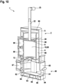
- figure 9 shows the entire dosing dispenser 1 including the closed stand 40.
- figure 10 shows a sectional view figure 9 .
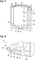
- figure 11 shows a sectional view of the receiving space 10.
- figure 12 shows a sectional view of the bag support base 6.
- figure 13 shows a portion of an outside of the housing 2.
- figure 14 shows an inlay 69.
- the stand 40 here forms a closed dispensing space 61 with stand side wall 62 and stand base 63.
- the stand side wall 62 completely surrounds a closed dispensing space 61 with the exception of a stand opening 64 cut out in the stand side wall 62 for inserting the container 41, a stand cover 65 for closing the stand opening 64 being arranged on the stand opening 64.
- the stand side wall 62 and the stand base 63 each have at least one cavity 66 for thermal insulation, preferably filled with thermally insulating material.
- the bag support base 6 comprises an annular outer area 71 and a valve support area 72 that is lower than the outer area 71 .
- the Bag support base 6, here the outer area 71 is designed conically in such a way that it is lower radially on the outside than radially on the inside. As a result, condensed water flows radially outwards.
- the outer area 71 and the valve support area 72 each comprise at least one condensation drainage opening 73 and a condensation collection channel 75 as well as projections 74 in the form of knobs for spacing the bag 42.
- a stand temperature control unit 67 is provided for active temperature control of the delivery space 61 , the stand temperature control unit 67 being arranged on the side wall 62 of the stand.
- the space 14 is formed here as a cavity 66 between a double wall.
- the double wall is formed on the inside by the wall 9 of the receiving space and on the outside by the side wall 4 of the housing 2 .
- the cavity 66 is used for thermal insulation and is preferably filled with thermally insulating material.
- the dosing dispenser 1 comprises two receiving space temperature control units 68 which are arranged radially outside of the receiving space wall 9 .
- Two unit spaces 80 are formed in the housing 2 , which are delimited radially on the inside by the receiving space wall 9 and are open radially on the outside, with the respective receiving space temperature control unit 68 being partially arranged in the associated unit space 80 .
- the unit spaces 80 have cooling openings 70 in the receiving space wall 9 for direct contact between the receiving space temperature control unit 68 and the inlay 69 .
- a retaining bracket 76 fixes both receiving space temperature control units 68 on the housing 2.
- a metal inlay 69 for transferring cooling or heating power to the bag 42 is arranged in the receiving space 10, the inlay 69 (see half section in figure 14 ) includes a full-circumferential tube portion 77 and an annular bottom portion 78 .
- Condensed water recesses 79 are formed in the base area 78 for conducting the condensed water downwards to the bag support base 6 .
- the bag support base 6 has cavities 66 for thermal insulation, preferably filled with thermally insulating material.
- the stamp 20 has cavities 66 for thermal insulation, preferably filled with thermally insulating material.
- a horizontal area of the housing 2 above the receiving space 10, in particular the support area 5, has at least one cavity 66 for thermal insulation, preferably filled with thermally insulating material.
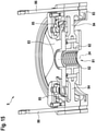
- figure 15 shows a sectional view of a possible design of the support area 5 for all exemplary embodiments, here designed as an upper closure of the housing 2.
- an internal thread 81 for receiving the transmission device (spindle) 22 is arranged.
- the internal thread 81 can be divided non-destructively for removal and/or quick adjustment of the spindle 22 .
- the internal thread 81 comprises two internal thread parts 82 which can be moved apart perpendicularly to the punch axis 24 .
- figure 15 shows a section in which half of the two internally threaded parts 82 is shown.
- two opposing threaded carriers 84 are arranged between two support area parts 83.
- An internally threaded portion 82 is attached to each threaded carrier 84 .
- the threaded carriers 84 are accommodated in the support area 5 so as to be linearly movable perpendicularly to the punch axis 24 .
- the threaded carriers 84 are secured against being pulled out completely by means of a stop 85 .
- the threaded carriers 84 are each fixed in position with a movable securing element 86 relative to the support area 5 , in particular the housing 2 .
- the securing elements 86 designed here as pins, can be detached without tools.
- figure 15 shows the released, pulled-up state of the securing element 86. In this state, the two thread carriers 84 can be pulled radially outwards.
Landscapes
- Physics & Mathematics (AREA)
- Fluid Mechanics (AREA)
- General Physics & Mathematics (AREA)
- Engineering & Computer Science (AREA)
- Mechanical Engineering (AREA)
- Devices For Dispensing Beverages (AREA)
- Containers And Packaging Bodies Having A Special Means To Remove Contents (AREA)
Claims (15)
- Distributeur doseur (1) destiné au commerce de détail et à la gastronomie, comprenant- un boîtier (2),- au moins un espace de réception (10) réalisé dans le boîtier (2) pour recevoir au moins un sachet (42) avec du produit visqueux,- par espace de réception (10) respectivement un poinçon (20) disposé dans l'espace de réception (10) pour exprimer le produit de l'au moins un sachet (42),- par poinçon (20) un dispositif d'actionnement (21) guidé dans le boîtier (2) et/ou prenant appui sur le boîtier, pour actionner de manière mobile linéairement le poinçon (20), et- au moins une ouverture de sortie (13), de préférence précisément une ouverture de sortie (13) par espace de réception, pour le produit, qui est réalisée dans la zone d'une première extrémité (11) de l'espace de réception (10),- dans lequel l'espace de réception respectif est formé par une paroi d'espace de réception cylindrique (9) et sur la première extrémité (11) par un fond de dépôt de sachet (6),
caractérisé en ce que- un espace libre (14) est formé entre la paroi d'espace de réception (9) et une paroi extérieure, de préférence une paroi extérieure latérale (4), du boîtier (2). - Distributeur doseur selon la revendication 1, dans lequel l'espace de réception (10) présente une deuxième extrémité (12) faisant face à la première extrémité (11), dans lequel l'espace de réception (10) sur la deuxième extrémité (12) est ouvert sur la totalité de la section transversale.
- Distributeur doseur selon l'une quelconque des revendications précédentes,- dans lequel l'espace de réception (10) jouxte par sa première extrémité (11) directement une paroi extérieure avec l'ouverture de sortie (13), de préférence la paroi extérieure de fond (3), du boîtier (2), dans lequel ladite paroi extérieure forme le fond de dépôt de sachet (6) ou- dans lequel l'espace de réception (10) est formé sur la première extrémité (11) par une paroi d'espace de réception cylindrique (9) et un fond d'espace de réception (56), qui forme le fond de dépôt de sachet (6), dans lequel l'ouverture de sortie (13) est réalisée dans le fond d'espace de réception (56), dans lequel la structure composée de la paroi d'espace de réception (9) et du fond d'espace de réception (56) est enfichée dans un évidement de la paroi extérieure, de préférence la paroi extérieure de fond (3), du boîtier (2).
- Distributeur doseur selon l'une quelconque des revendications précédentes, comprenant un socle (40), sur lequel le boîtier (10) se dresse si bien qu'un contenant (41) pour recevoir le produit peut être placé directement sous la/les ouverture(s) de sortie (13).
- Distributeur doseur selon la revendication 4, dans lequel le socle (40) forme un espace de distribution fermé (61) avec une paroi latérale de socle (62) et de préférence le fond de socle (63).
- Distributeur doseur selon la revendication 5, dans lequel la paroi latérale de socle (62) entoure totalement l'espace de distribution fermé (61) et une ouverture de socle (64) pour insérer le contenant (41) est évidée dans la paroi latérale de socle (62).
- Distributeur doseur selon l'une quelconque des revendications 5 ou 6, dans lequel la paroi latérale de socle (62) et/ou le fond de socle (63) présente/présentent respectivement au moins un espace creux (66) pour l'isolation thermique, de préférence avec remplissage d'un matériau thermo-isolant.
- Distributeur doseur selon l'une quelconque des revendications 5 à 7, comprenant un groupe de thermorégulation de socle (67) pour thermoréguler activement l'espace de distribution (61).
- Distributeur doseur selon l'une quelconque des revendications précédentes, dans lequel la paroi d'espace de réception (9) comprend une ouverture de remplissage ultérieur et un couvercle fermant l'ouverture de remplissage ultérieur, destiné à insérer le sachet (42).
- Distributeur doseur selon l'une quelconque des revendications précédentes, dans lequel la paroi d'espace de réception (9) y compris le fond de dépôt de sachet (6) peut être retirée latéralement, en particulier peut être sortie par pivotement, du boîtier (2) pour remplir l'espace de réception (10).
- Distributeur doseur selon l'une quelconque des revendications précédentes, dans lequel l'espace libre (14) est formé en totalité en périphérie, éventuellement de manière interrompue, par au moins un espace de groupe (80), et/ou le long de la totalité de la hauteur de la paroi d'espace de réception (9).
- Distributeur doseur selon l'une quelconque des revendications précédentes, dans lequel un matériau thermo-isolant est disposé dans l'espace libre (14), en particulier réalisé en tant qu'espace creux entre une double paroi.
- Distributeur doseur selon l'une quelconque des revendications précédentes, comprenant au moins un groupe de thermorégulation d'espace de réception (68), qui est disposé en particulier radialement à l'extérieur de la paroi d'espace de réception (9).
- Distributeur doseur selon la revendication 13, dans lequel est formé dans le boîtier (2) un espace de groupe (80), qui est délimité radialement à l'intérieur par la paroi d'espace de réception (9), dans lequel le groupe de thermorégulation d'espace de réception (68) est disposé en totalité ou en partie dans l'espace de groupe (80).
- Distributeur doseur selon l'une quelconque des revendications précédentes, dans lequel au moins un inlay (69) métallique pour la transmission d'une puissance frigorifique ou thermique est disposé sur le sachet (42) dans l'espace de réception (10), en particulier en vue du contact direct avec le sachet (42).
Applications Claiming Priority (2)
| Application Number | Priority Date | Filing Date | Title |
|---|---|---|---|
| DE102018214532.6A DE102018214532A1 (de) | 2018-08-28 | 2018-08-28 | Dosierspender |
| PCT/EP2019/072024 WO2020043512A1 (fr) | 2018-08-28 | 2019-08-16 | Distributeur de dosage |
Publications (2)
| Publication Number | Publication Date |
|---|---|
| EP3844094A1 EP3844094A1 (fr) | 2021-07-07 |
| EP3844094B1 true EP3844094B1 (fr) | 2022-02-16 |
Family
ID=67704506
Family Applications (1)
| Application Number | Title | Priority Date | Filing Date |
|---|---|---|---|
| EP19756340.6A Active EP3844094B1 (fr) | 2018-08-28 | 2019-08-16 | Distributeur de dosage |
Country Status (3)
| Country | Link |
|---|---|
| EP (1) | EP3844094B1 (fr) |
| DE (1) | DE102018214532A1 (fr) |
| WO (1) | WO2020043512A1 (fr) |
Families Citing this family (1)
| Publication number | Priority date | Publication date | Assignee | Title |
|---|---|---|---|---|
| CN119522188A (zh) * | 2022-07-15 | 2025-02-25 | 阿维瑞技术股份有限公司 | 从袋容器卸载高粘度流体产品 |
Family Cites Families (11)
| Publication number | Priority date | Publication date | Assignee | Title |
|---|---|---|---|---|
| CH674828A5 (fr) * | 1987-10-23 | 1990-07-31 | Gurit Essex Ag | |
| GB8905629D0 (en) * | 1989-03-11 | 1989-04-26 | Mcgill Shane R | Dispensing apparatus |
| FR2665767B1 (fr) * | 1990-08-08 | 1994-12-23 | Jagenberg Ag | Procede et dispositif de reglage des quantites de produit dosees et distribuees par un doseur-distributeur. |
| GB9024916D0 (en) * | 1990-11-16 | 1991-01-02 | Du Pont Canada | Improved pouch dispenser |
| DE4216541C2 (de) * | 1992-05-19 | 1995-02-16 | Sigismund Laskowski | Mehrfach verwendbarer Dosierspender |
| US5553740A (en) * | 1994-11-18 | 1996-09-10 | Restaurant Automation Development Co. | Apparatus and method for pumping controlled amounts of flowable material from a flexible bag |
| DE20001409U1 (de) * | 2000-01-27 | 2000-04-20 | Siemens AG, 80333 München | Vorrichtung zur dosierten Abgabe von flüssigen oder pastösen Lebensmitteln |
| SE530703C2 (sv) * | 2006-12-22 | 2008-08-19 | Asept Int Ab | Anordning för utportionering samt utportioneringsorgan till sådan anordning |
| DE102009049899A1 (de) * | 2009-10-13 | 2011-04-14 | Rost, Stephan, Dr. | Gewürzstreuersystem |
| GB2504289A (en) * | 2012-07-24 | 2014-01-29 | Rifat Jan | Paste dispenser and paste receiving pouches |
| US9597706B2 (en) * | 2013-03-15 | 2017-03-21 | Rooftop Research, Llc | Container and substance dispensing system |
-
2018
- 2018-08-28 DE DE102018214532.6A patent/DE102018214532A1/de not_active Withdrawn
-
2019
- 2019-08-16 WO PCT/EP2019/072024 patent/WO2020043512A1/fr not_active Ceased
- 2019-08-16 EP EP19756340.6A patent/EP3844094B1/fr active Active
Also Published As
| Publication number | Publication date |
|---|---|
| EP3844094A1 (fr) | 2021-07-07 |
| WO2020043512A1 (fr) | 2020-03-05 |
| DE102018214532A1 (de) | 2020-03-05 |
Similar Documents
| Publication | Publication Date | Title |
|---|---|---|
| DE60007332T2 (de) | Ausgabebehältnis und maschine | |
| DE69426023T2 (de) | Kindersichere dosiervorrichtung | |
| DE69730742T3 (de) | Behälter mit zwei oder mehr abteilungen | |
| DE69029320T2 (de) | Dosierungsvorrichtung | |
| EP3997338B1 (fr) | Systeme de levage pour distribuer un fluide d'un récipient et récipient pour un fluide | |
| EP2695548A1 (fr) | Distributeur pour le dosage de fluides pouvant s'écouler | |
| DE10353445A1 (de) | Spenderbehältnis und Vorratsbehältnis für analytische Verbrauchsmittel | |
| DE2036460A1 (de) | Massengutabgabeanordnung | |
| DE69927825T2 (de) | Ausgiesser für flüssigkeitsbehälter | |
| DE102013108007B3 (de) | Babynahrungsdosiervorrichtung | |
| EP3844094A1 (fr) | Distributeur de dosage | |
| AT504637B1 (de) | Vorrichtung zur abgabe von flüssigen oder pastösen lebensmitteln | |
| WO2007113192A1 (fr) | sac à boisson doté d'une poche mobile pour un distributeur servant de système de prélèvement de boissons et procédé d'utilisation associé | |
| EP2634134A2 (fr) | Dispositif de distribution de boissons | |
| EP2181960B1 (fr) | Distributeur de prémélanges avec sachet pour boissons et à haute capacité de refroidissement | |
| DE3544748A1 (de) | Vorrichtung zur dosierten ausgabe von fliessfaehigen medien | |
| DE3789784T2 (de) | Dosierende Spender. | |
| DE19821651A1 (de) | Verfahren zum Bereitstellen eines Teigproduktes und Vorrichtung zur Durchführung des Verfahrens | |
| JP2018519221A (ja) | 殺菌インサートを有する容器 | |
| DE69624074T2 (de) | Durchflusswegwählvorrichtung | |
| DE102009043193A1 (de) | Abgeschlossenes, deckelintegriertes Dosiersystem für Nahrungsmittelbehältnisse zur hygienischen Portionierung von fließfähigen Nahrungsmitteln | |
| EP3900923A1 (fr) | Procédé de fabrication automatisée de comprimés individualisés et presse à comprimés destinée à la fabrication automatisée de comprimés individualisés | |
| DE102008059642B4 (de) | Dosiervorrichtung | |
| DE3236552A1 (de) | Pump-dosierverschluss | |
| DE9114994U1 (de) | Spender für Marmelade, Gelee, Honig o.dgl. |
Legal Events
| Date | Code | Title | Description |
|---|---|---|---|
| STAA | Information on the status of an ep patent application or granted ep patent |
Free format text: STATUS: UNKNOWN |
|
| STAA | Information on the status of an ep patent application or granted ep patent |
Free format text: STATUS: THE INTERNATIONAL PUBLICATION HAS BEEN MADE |
|
| STAA | Information on the status of an ep patent application or granted ep patent |
Free format text: STATUS: REQUEST FOR EXAMINATION WAS MADE |
|
| PUAI | Public reference made under article 153(3) epc to a published international application that has entered the european phase |
Free format text: ORIGINAL CODE: 0009012 |
|
| 17P | Request for examination filed |
Effective date: 20210126 |
|
| AK | Designated contracting states |
Kind code of ref document: A1 Designated state(s): AL AT BE BG CH CY CZ DE DK EE ES FI FR GB GR HR HU IE IS IT LI LT LU LV MC MK MT NL NO PL PT RO RS SE SI SK SM TR |
|
| GRAP | Despatch of communication of intention to grant a patent |
Free format text: ORIGINAL CODE: EPIDOSNIGR1 |
|
| STAA | Information on the status of an ep patent application or granted ep patent |
Free format text: STATUS: GRANT OF PATENT IS INTENDED |
|
| DAV | Request for validation of the european patent (deleted) | ||
| DAX | Request for extension of the european patent (deleted) | ||
| INTG | Intention to grant announced |
Effective date: 20211019 |
|
| GRAS | Grant fee paid |
Free format text: ORIGINAL CODE: EPIDOSNIGR3 |
|
| GRAA | (expected) grant |
Free format text: ORIGINAL CODE: 0009210 |
|
| STAA | Information on the status of an ep patent application or granted ep patent |
Free format text: STATUS: THE PATENT HAS BEEN GRANTED |
|
| AK | Designated contracting states |
Kind code of ref document: B1 Designated state(s): AL AT BE BG CH CY CZ DE DK EE ES FI FR GB GR HR HU IE IS IT LI LT LU LV MC MK MT NL NO PL PT RO RS SE SI SK SM TR |
|
| RAP3 | Party data changed (applicant data changed or rights of an application transferred) |
Owner name: HOCHSCHULE FUER ANGEWANDTE WISSENSCHAFTEN KEMPTEN |
|
| REG | Reference to a national code |
Ref country code: GB Ref legal event code: FG4D Free format text: NOT ENGLISH |
|
| REG | Reference to a national code |
Ref country code: CH Ref legal event code: EP |
|
| REG | Reference to a national code |
Ref country code: DE Ref legal event code: R096 Ref document number: 502019003448 Country of ref document: DE |
|
| REG | Reference to a national code |
Ref country code: AT Ref legal event code: REF Ref document number: 1468770 Country of ref document: AT Kind code of ref document: T Effective date: 20220315 |
|
| REG | Reference to a national code |
Ref country code: IE Ref legal event code: FG4D Free format text: LANGUAGE OF EP DOCUMENT: GERMAN |
|
| REG | Reference to a national code |
Ref country code: LT Ref legal event code: MG9D |
|
| REG | Reference to a national code |
Ref country code: NL Ref legal event code: MP Effective date: 20220216 |
|
| PG25 | Lapsed in a contracting state [announced via postgrant information from national office to epo] |
Ref country code: SE Free format text: LAPSE BECAUSE OF FAILURE TO SUBMIT A TRANSLATION OF THE DESCRIPTION OR TO PAY THE FEE WITHIN THE PRESCRIBED TIME-LIMIT Effective date: 20220216 Ref country code: RS Free format text: LAPSE BECAUSE OF FAILURE TO SUBMIT A TRANSLATION OF THE DESCRIPTION OR TO PAY THE FEE WITHIN THE PRESCRIBED TIME-LIMIT Effective date: 20220216 Ref country code: PT Free format text: LAPSE BECAUSE OF FAILURE TO SUBMIT A TRANSLATION OF THE DESCRIPTION OR TO PAY THE FEE WITHIN THE PRESCRIBED TIME-LIMIT Effective date: 20220616 Ref country code: NO Free format text: LAPSE BECAUSE OF FAILURE TO SUBMIT A TRANSLATION OF THE DESCRIPTION OR TO PAY THE FEE WITHIN THE PRESCRIBED TIME-LIMIT Effective date: 20220516 Ref country code: NL Free format text: LAPSE BECAUSE OF FAILURE TO SUBMIT A TRANSLATION OF THE DESCRIPTION OR TO PAY THE FEE WITHIN THE PRESCRIBED TIME-LIMIT Effective date: 20220216 Ref country code: LT Free format text: LAPSE BECAUSE OF FAILURE TO SUBMIT A TRANSLATION OF THE DESCRIPTION OR TO PAY THE FEE WITHIN THE PRESCRIBED TIME-LIMIT Effective date: 20220216 Ref country code: HR Free format text: LAPSE BECAUSE OF FAILURE TO SUBMIT A TRANSLATION OF THE DESCRIPTION OR TO PAY THE FEE WITHIN THE PRESCRIBED TIME-LIMIT Effective date: 20220216 Ref country code: ES Free format text: LAPSE BECAUSE OF FAILURE TO SUBMIT A TRANSLATION OF THE DESCRIPTION OR TO PAY THE FEE WITHIN THE PRESCRIBED TIME-LIMIT Effective date: 20220216 Ref country code: BG Free format text: LAPSE BECAUSE OF FAILURE TO SUBMIT A TRANSLATION OF THE DESCRIPTION OR TO PAY THE FEE WITHIN THE PRESCRIBED TIME-LIMIT Effective date: 20220516 |
|
| PG25 | Lapsed in a contracting state [announced via postgrant information from national office to epo] |
Ref country code: PL Free format text: LAPSE BECAUSE OF FAILURE TO SUBMIT A TRANSLATION OF THE DESCRIPTION OR TO PAY THE FEE WITHIN THE PRESCRIBED TIME-LIMIT Effective date: 20220216 Ref country code: LV Free format text: LAPSE BECAUSE OF FAILURE TO SUBMIT A TRANSLATION OF THE DESCRIPTION OR TO PAY THE FEE WITHIN THE PRESCRIBED TIME-LIMIT Effective date: 20220216 Ref country code: GR Free format text: LAPSE BECAUSE OF FAILURE TO SUBMIT A TRANSLATION OF THE DESCRIPTION OR TO PAY THE FEE WITHIN THE PRESCRIBED TIME-LIMIT Effective date: 20220517 Ref country code: FI Free format text: LAPSE BECAUSE OF FAILURE TO SUBMIT A TRANSLATION OF THE DESCRIPTION OR TO PAY THE FEE WITHIN THE PRESCRIBED TIME-LIMIT Effective date: 20220216 |
|
| PG25 | Lapsed in a contracting state [announced via postgrant information from national office to epo] |
Ref country code: IS Free format text: LAPSE BECAUSE OF FAILURE TO SUBMIT A TRANSLATION OF THE DESCRIPTION OR TO PAY THE FEE WITHIN THE PRESCRIBED TIME-LIMIT Effective date: 20220617 |
|
| PG25 | Lapsed in a contracting state [announced via postgrant information from national office to epo] |
Ref country code: SM Free format text: LAPSE BECAUSE OF FAILURE TO SUBMIT A TRANSLATION OF THE DESCRIPTION OR TO PAY THE FEE WITHIN THE PRESCRIBED TIME-LIMIT Effective date: 20220216 Ref country code: SK Free format text: LAPSE BECAUSE OF FAILURE TO SUBMIT A TRANSLATION OF THE DESCRIPTION OR TO PAY THE FEE WITHIN THE PRESCRIBED TIME-LIMIT Effective date: 20220216 Ref country code: RO Free format text: LAPSE BECAUSE OF FAILURE TO SUBMIT A TRANSLATION OF THE DESCRIPTION OR TO PAY THE FEE WITHIN THE PRESCRIBED TIME-LIMIT Effective date: 20220216 Ref country code: EE Free format text: LAPSE BECAUSE OF FAILURE TO SUBMIT A TRANSLATION OF THE DESCRIPTION OR TO PAY THE FEE WITHIN THE PRESCRIBED TIME-LIMIT Effective date: 20220216 Ref country code: DK Free format text: LAPSE BECAUSE OF FAILURE TO SUBMIT A TRANSLATION OF THE DESCRIPTION OR TO PAY THE FEE WITHIN THE PRESCRIBED TIME-LIMIT Effective date: 20220216 Ref country code: CZ Free format text: LAPSE BECAUSE OF FAILURE TO SUBMIT A TRANSLATION OF THE DESCRIPTION OR TO PAY THE FEE WITHIN THE PRESCRIBED TIME-LIMIT Effective date: 20220216 |
|
| REG | Reference to a national code |
Ref country code: DE Ref legal event code: R097 Ref document number: 502019003448 Country of ref document: DE |
|
| PG25 | Lapsed in a contracting state [announced via postgrant information from national office to epo] |
Ref country code: AL Free format text: LAPSE BECAUSE OF FAILURE TO SUBMIT A TRANSLATION OF THE DESCRIPTION OR TO PAY THE FEE WITHIN THE PRESCRIBED TIME-LIMIT Effective date: 20220216 |
|
| PLBE | No opposition filed within time limit |
Free format text: ORIGINAL CODE: 0009261 |
|
| STAA | Information on the status of an ep patent application or granted ep patent |
Free format text: STATUS: NO OPPOSITION FILED WITHIN TIME LIMIT |
|
| 26N | No opposition filed |
Effective date: 20221117 |
|
| PG25 | Lapsed in a contracting state [announced via postgrant information from national office to epo] |
Ref country code: MC Free format text: LAPSE BECAUSE OF FAILURE TO SUBMIT A TRANSLATION OF THE DESCRIPTION OR TO PAY THE FEE WITHIN THE PRESCRIBED TIME-LIMIT Effective date: 20220216 |
|
| PG25 | Lapsed in a contracting state [announced via postgrant information from national office to epo] |
Ref country code: LU Free format text: LAPSE BECAUSE OF NON-PAYMENT OF DUE FEES Effective date: 20220816 |
|
| REG | Reference to a national code |
Ref country code: BE Ref legal event code: MM Effective date: 20220831 |
|
| PG25 | Lapsed in a contracting state [announced via postgrant information from national office to epo] |
Ref country code: IT Free format text: LAPSE BECAUSE OF FAILURE TO SUBMIT A TRANSLATION OF THE DESCRIPTION OR TO PAY THE FEE WITHIN THE PRESCRIBED TIME-LIMIT Effective date: 20220216 Ref country code: IE Free format text: LAPSE BECAUSE OF NON-PAYMENT OF DUE FEES Effective date: 20220816 |
|
| PG25 | Lapsed in a contracting state [announced via postgrant information from national office to epo] |
Ref country code: BE Free format text: LAPSE BECAUSE OF NON-PAYMENT OF DUE FEES Effective date: 20220831 |
|
| PG25 | Lapsed in a contracting state [announced via postgrant information from national office to epo] |
Ref country code: CY Free format text: LAPSE BECAUSE OF FAILURE TO SUBMIT A TRANSLATION OF THE DESCRIPTION OR TO PAY THE FEE WITHIN THE PRESCRIBED TIME-LIMIT Effective date: 20220216 |
|
| PG25 | Lapsed in a contracting state [announced via postgrant information from national office to epo] |
Ref country code: MK Free format text: LAPSE BECAUSE OF FAILURE TO SUBMIT A TRANSLATION OF THE DESCRIPTION OR TO PAY THE FEE WITHIN THE PRESCRIBED TIME-LIMIT Effective date: 20220216 Ref country code: HU Free format text: LAPSE BECAUSE OF FAILURE TO SUBMIT A TRANSLATION OF THE DESCRIPTION OR TO PAY THE FEE WITHIN THE PRESCRIBED TIME-LIMIT; INVALID AB INITIO Effective date: 20190816 |
|
| PG25 | Lapsed in a contracting state [announced via postgrant information from national office to epo] |
Ref country code: MT Free format text: LAPSE BECAUSE OF FAILURE TO SUBMIT A TRANSLATION OF THE DESCRIPTION OR TO PAY THE FEE WITHIN THE PRESCRIBED TIME-LIMIT Effective date: 20220216 |
|
| PGFP | Annual fee paid to national office [announced via postgrant information from national office to epo] |
Ref country code: DE Payment date: 20250828 Year of fee payment: 7 |
|
| PGFP | Annual fee paid to national office [announced via postgrant information from national office to epo] |
Ref country code: GB Payment date: 20250818 Year of fee payment: 7 |
|
| PGFP | Annual fee paid to national office [announced via postgrant information from national office to epo] |
Ref country code: FR Payment date: 20250827 Year of fee payment: 7 Ref country code: AT Payment date: 20250819 Year of fee payment: 7 |
|
| PGFP | Annual fee paid to national office [announced via postgrant information from national office to epo] |
Ref country code: CH Payment date: 20250901 Year of fee payment: 7 |
|
| PG25 | Lapsed in a contracting state [announced via postgrant information from national office to epo] |
Ref country code: TR Free format text: LAPSE BECAUSE OF FAILURE TO SUBMIT A TRANSLATION OF THE DESCRIPTION OR TO PAY THE FEE WITHIN THE PRESCRIBED TIME-LIMIT Effective date: 20220216 |
|
| PG25 | Lapsed in a contracting state [announced via postgrant information from national office to epo] |
Ref country code: SI Free format text: LAPSE BECAUSE OF FAILURE TO SUBMIT A TRANSLATION OF THE DESCRIPTION OR TO PAY THE FEE WITHIN THE PRESCRIBED TIME-LIMIT Effective date: 20220216 |