EP3844075B1 - Gehäuseeinheit für einen lastträger, lastträger und zugehöriges verfahren - Google Patents
Gehäuseeinheit für einen lastträger, lastträger und zugehöriges verfahren Download PDFInfo
- Publication number
- EP3844075B1 EP3844075B1 EP19855555.9A EP19855555A EP3844075B1 EP 3844075 B1 EP3844075 B1 EP 3844075B1 EP 19855555 A EP19855555 A EP 19855555A EP 3844075 B1 EP3844075 B1 EP 3844075B1
- Authority
- EP
- European Patent Office
- Prior art keywords
- capsule
- sleeve
- housing unit
- load carrier
- chamber
- Prior art date
- Legal status (The legal status is an assumption and is not a legal conclusion. Google has not performed a legal analysis and makes no representation as to the accuracy of the status listed.)
- Active
Links
Images


Classifications
-
- B—PERFORMING OPERATIONS; TRANSPORTING
- B65—CONVEYING; PACKING; STORING; HANDLING THIN OR FILAMENTARY MATERIAL
- B65D—CONTAINERS FOR STORAGE OR TRANSPORT OF ARTICLES OR MATERIALS, e.g. BAGS, BARRELS, BOTTLES, BOXES, CANS, CARTONS, CRATES, DRUMS, JARS, TANKS, HOPPERS, FORWARDING CONTAINERS; ACCESSORIES, CLOSURES, OR FITTINGS THEREFOR; PACKAGING ELEMENTS; PACKAGES
- B65D19/00—Pallets or like platforms, with or without side walls, for supporting loads to be lifted or lowered
- B65D19/38—Details or accessories
- B65D19/385—Frames, corner posts or pallet converters, e.g. for facilitating stacking of charged pallets
-
- B—PERFORMING OPERATIONS; TRANSPORTING
- B65—CONVEYING; PACKING; STORING; HANDLING THIN OR FILAMENTARY MATERIAL
- B65D—CONTAINERS FOR STORAGE OR TRANSPORT OF ARTICLES OR MATERIALS, e.g. BAGS, BARRELS, BOTTLES, BOXES, CANS, CARTONS, CRATES, DRUMS, JARS, TANKS, HOPPERS, FORWARDING CONTAINERS; ACCESSORIES, CLOSURES, OR FITTINGS THEREFOR; PACKAGING ELEMENTS; PACKAGES
- B65D19/00—Pallets or like platforms, with or without side walls, for supporting loads to be lifted or lowered
- B65D19/0004—Rigid pallets without side walls
- B65D19/0006—Rigid pallets without side walls the load supporting surface being made of a single element
- B65D19/0008—Rigid pallets without side walls the load supporting surface being made of a single element forming a continuous plane contact surface
- B65D19/001—Rigid pallets without side walls the load supporting surface being made of a single element forming a continuous plane contact surface the base surface being made of a single element
- B65D19/0012—Rigid pallets without side walls the load supporting surface being made of a single element forming a continuous plane contact surface the base surface being made of a single element forming a continuous plane contact surface
-
- B—PERFORMING OPERATIONS; TRANSPORTING
- B65—CONVEYING; PACKING; STORING; HANDLING THIN OR FILAMENTARY MATERIAL
- B65D—CONTAINERS FOR STORAGE OR TRANSPORT OF ARTICLES OR MATERIALS, e.g. BAGS, BARRELS, BOTTLES, BOXES, CANS, CARTONS, CRATES, DRUMS, JARS, TANKS, HOPPERS, FORWARDING CONTAINERS; ACCESSORIES, CLOSURES, OR FITTINGS THEREFOR; PACKAGING ELEMENTS; PACKAGES
- B65D2203/00—Decoration means, markings, information elements, contents indicators
- B65D2203/10—Transponders
-
- B—PERFORMING OPERATIONS; TRANSPORTING
- B65—CONVEYING; PACKING; STORING; HANDLING THIN OR FILAMENTARY MATERIAL
- B65D—CONTAINERS FOR STORAGE OR TRANSPORT OF ARTICLES OR MATERIALS, e.g. BAGS, BARRELS, BOTTLES, BOXES, CANS, CARTONS, CRATES, DRUMS, JARS, TANKS, HOPPERS, FORWARDING CONTAINERS; ACCESSORIES, CLOSURES, OR FITTINGS THEREFOR; PACKAGING ELEMENTS; PACKAGES
- B65D2519/00—Pallets or like platforms, with or without side walls, for supporting loads to be lifted or lowered
- B65D2519/00004—Details relating to pallets
- B65D2519/00009—Materials
- B65D2519/00014—Materials for the load supporting surface
- B65D2519/00034—Plastic
-
- B—PERFORMING OPERATIONS; TRANSPORTING
- B65—CONVEYING; PACKING; STORING; HANDLING THIN OR FILAMENTARY MATERIAL
- B65D—CONTAINERS FOR STORAGE OR TRANSPORT OF ARTICLES OR MATERIALS, e.g. BAGS, BARRELS, BOTTLES, BOXES, CANS, CARTONS, CRATES, DRUMS, JARS, TANKS, HOPPERS, FORWARDING CONTAINERS; ACCESSORIES, CLOSURES, OR FITTINGS THEREFOR; PACKAGING ELEMENTS; PACKAGES
- B65D2519/00—Pallets or like platforms, with or without side walls, for supporting loads to be lifted or lowered
- B65D2519/00004—Details relating to pallets
- B65D2519/00009—Materials
- B65D2519/00049—Materials for the base surface
- B65D2519/00069—Plastic
-
- B—PERFORMING OPERATIONS; TRANSPORTING
- B65—CONVEYING; PACKING; STORING; HANDLING THIN OR FILAMENTARY MATERIAL
- B65D—CONTAINERS FOR STORAGE OR TRANSPORT OF ARTICLES OR MATERIALS, e.g. BAGS, BARRELS, BOTTLES, BOXES, CANS, CARTONS, CRATES, DRUMS, JARS, TANKS, HOPPERS, FORWARDING CONTAINERS; ACCESSORIES, CLOSURES, OR FITTINGS THEREFOR; PACKAGING ELEMENTS; PACKAGES
- B65D2519/00—Pallets or like platforms, with or without side walls, for supporting loads to be lifted or lowered
- B65D2519/00004—Details relating to pallets
- B65D2519/00258—Overall construction
- B65D2519/00283—Overall construction of the load supporting surface
- B65D2519/00288—Overall construction of the load supporting surface made of one piece
-
- B—PERFORMING OPERATIONS; TRANSPORTING
- B65—CONVEYING; PACKING; STORING; HANDLING THIN OR FILAMENTARY MATERIAL
- B65D—CONTAINERS FOR STORAGE OR TRANSPORT OF ARTICLES OR MATERIALS, e.g. BAGS, BARRELS, BOTTLES, BOXES, CANS, CARTONS, CRATES, DRUMS, JARS, TANKS, HOPPERS, FORWARDING CONTAINERS; ACCESSORIES, CLOSURES, OR FITTINGS THEREFOR; PACKAGING ELEMENTS; PACKAGES
- B65D2519/00—Pallets or like platforms, with or without side walls, for supporting loads to be lifted or lowered
- B65D2519/00004—Details relating to pallets
- B65D2519/00258—Overall construction
- B65D2519/00283—Overall construction of the load supporting surface
- B65D2519/00308—Overall construction of the load supporting surface grid type, e.g. perforated plate
-
- B—PERFORMING OPERATIONS; TRANSPORTING
- B65—CONVEYING; PACKING; STORING; HANDLING THIN OR FILAMENTARY MATERIAL
- B65D—CONTAINERS FOR STORAGE OR TRANSPORT OF ARTICLES OR MATERIALS, e.g. BAGS, BARRELS, BOTTLES, BOXES, CANS, CARTONS, CRATES, DRUMS, JARS, TANKS, HOPPERS, FORWARDING CONTAINERS; ACCESSORIES, CLOSURES, OR FITTINGS THEREFOR; PACKAGING ELEMENTS; PACKAGES
- B65D2519/00—Pallets or like platforms, with or without side walls, for supporting loads to be lifted or lowered
- B65D2519/00004—Details relating to pallets
- B65D2519/00258—Overall construction
- B65D2519/00313—Overall construction of the base surface
- B65D2519/00328—Overall construction of the base surface shape of the contact surface of the base
- B65D2519/00333—Overall construction of the base surface shape of the contact surface of the base contact surface having a stringer-like shape
-
- B—PERFORMING OPERATIONS; TRANSPORTING
- B65—CONVEYING; PACKING; STORING; HANDLING THIN OR FILAMENTARY MATERIAL
- B65D—CONTAINERS FOR STORAGE OR TRANSPORT OF ARTICLES OR MATERIALS, e.g. BAGS, BARRELS, BOTTLES, BOXES, CANS, CARTONS, CRATES, DRUMS, JARS, TANKS, HOPPERS, FORWARDING CONTAINERS; ACCESSORIES, CLOSURES, OR FITTINGS THEREFOR; PACKAGING ELEMENTS; PACKAGES
- B65D2519/00—Pallets or like platforms, with or without side walls, for supporting loads to be lifted or lowered
- B65D2519/00004—Details relating to pallets
- B65D2519/00258—Overall construction
- B65D2519/00398—Overall construction reinforcements
- B65D2519/00402—Integral, e.g. ribs
-
- B—PERFORMING OPERATIONS; TRANSPORTING
- B65—CONVEYING; PACKING; STORING; HANDLING THIN OR FILAMENTARY MATERIAL
- B65D—CONTAINERS FOR STORAGE OR TRANSPORT OF ARTICLES OR MATERIALS, e.g. BAGS, BARRELS, BOTTLES, BOXES, CANS, CARTONS, CRATES, DRUMS, JARS, TANKS, HOPPERS, FORWARDING CONTAINERS; ACCESSORIES, CLOSURES, OR FITTINGS THEREFOR; PACKAGING ELEMENTS; PACKAGES
- B65D2519/00—Pallets or like platforms, with or without side walls, for supporting loads to be lifted or lowered
- B65D2519/00004—Details relating to pallets
- B65D2519/00736—Details
- B65D2519/00776—Accessories for manipulating the pallet
- B65D2519/00796—Guiding means for fork-lift
-
- B—PERFORMING OPERATIONS; TRANSPORTING
- B65—CONVEYING; PACKING; STORING; HANDLING THIN OR FILAMENTARY MATERIAL
- B65D—CONTAINERS FOR STORAGE OR TRANSPORT OF ARTICLES OR MATERIALS, e.g. BAGS, BARRELS, BOTTLES, BOXES, CANS, CARTONS, CRATES, DRUMS, JARS, TANKS, HOPPERS, FORWARDING CONTAINERS; ACCESSORIES, CLOSURES, OR FITTINGS THEREFOR; PACKAGING ELEMENTS; PACKAGES
- B65D2519/00—Pallets or like platforms, with or without side walls, for supporting loads to be lifted or lowered
- B65D2519/00004—Details relating to pallets
- B65D2519/00736—Details
- B65D2519/0098—Dismountable elements
- B65D2519/0099—Dismountable elements single dismountable pallet element, e.g. for replacement
Definitions
- This invention relates to a housing unit for a load carrier. It finds particular, although by no means exclusive, use with load carriers such as pallets, crates, boxes and containers.
- Supply chain management and logistics management is constantly evolving to provide better and more efficient control, monitoring and auditing of goods as they progress through the supply chain.
- load carriers are often provided with electronic circuitry to enable the identification and tracking of individual loads as well as the monitoring of the conditions to which the load is subjected.
- the electronic circuitry may include a radio-frequency identification (RFID) tag or a near-field communication (NFC) tag to allow a load carrier to be uniquely identified.
- RFID radio-frequency identification
- NFC near-field communication
- the electronic circuitry may further include a satellite positioning module, such as a global positioning system module, to allow the electronic circuitry to determine its own location and thus that of the load carrier.
- Sensors such as humidity sensors, temperature sensors and accelerometers, may also be included in the electronic circuitry to log and report the conditions to which the load is subjected.
- Radio frequency communication modules may further be included to enable remote communication with the electronic circuitry and microprocessors to control and interrogate the above-mentioned, and other, components.
- a source of power such as a battery, may be provided for energising the electronic circuitry and its associated components.
- the electronic circuitry needs to be attached or otherwise secured to the load carrier in a manner that preserves the integrity of the circuitry and resists tampering therewith.
- High quality load carriers such as plastic pallets, may have lifespans exceeding 10 years. Maintenance, upgrade, or replacement of the electronic circuitry and firmware executing thereon may be required during the lifespan of the load carrier. Therefore, access to the electronic circuitry may be required from time to time.
- Korean patent no. KR101207673 (B1 ) discloses a Radio Frequency Identification (RFID) tag holder for a pallet including a first holder, a second holder, latch members, and a fixing unit.
- RFID Radio Frequency Identification
- Japanese patent application published as JP2015224048 (A ) discloses a tag holder including a tag holding part which holds an integrated circuit (IC) tag.
- a housing unit comprising a sleeve defining a chamber, and a capsule arranged to house an electronic device therein, the capsule being shaped and configured to be received in the chamber; wherein the sleeve and capsule have cooperating securing formations arranged to enable the capsule to be releasably secured within the chamber, and wherein the sleeve is shaped and configured to enable the sleeve to fit into a cavity in a load carrier, characterized in that an end of the capsule has a slot or keyhole t99t defined therein to enable the use of a tool or key to facilitate securing of the capsule in the chamber, and wherein the slot or keyhole is operable with the use of a tool or key to either secure the capsule in the sleeve or to release the capsule from the sleeve.
- the securing formations to include a female securing formation and a complementary male securing formation that are configured to be mated to each another; and for one of the male and female securing formations to be associated with the sleeve and for the other to be associated with the capsule.
- the securing formation is a bayonet mount.
- the male securing formation is a sloped tooth-like protrusion and the female securing formation is a spring-loaded catch having an aperture arranged to catch onto an edge of the tooth-like protrusion when the capsule is received in the chamber.
- the securing formation is screw thread.
- the sleeve to form a friction fit within the cavity in the load carrier; for the sleeve to include one or more gripping structures arranged to enhance the friction fit; for the gripping structures to include one or more gripping projections extending outwardly therefrom; for the gripping projections to be barbs arranged to resist removal of the sleeve from the cavity; and for the gripping structure to be an elongate gripper plate with gripping projections spaced along the plate.
- a still further feature provides for an outer end of the capsule to be flush with an open end of the chamber when removably secured therein.
- the housing unit to include a tamper indication mechanism arranged to enable detection of one or both of removal of the capsule from the sleeve and insertion of the capsule into the sleeve.
- the tamper indication mechanism to include a tamper-evident locking member arranged to fit into the outer end of the capsule; for the tamper-evident locking member to be configured to seat in the slot defined in the outer end of the capsule; and for the tamper-evident locking member to include a magnet to enable an electronic device held in the capsule to detect the removal of the locking member based on a detected magnetic field as a precursor to the removal of the capsule from the sleeve.
- the tamper indication mechanism to include a magnet located in the sleeve arranged to enable a sensor housed in the capsule to detect one or both of removal of the capsule from the sleeve and insertion of the capsule into the sleeve based on a detected magnetic field.
- the housing unit to include a spring that is interposed between an inner end of the chamber and the capsule when the capsule is secured in the chamber; for the spring to be secured to the inner end of the chamber; and for the spring to be configured to at least partially push the capsule outwardly from the chamber when the securing formation is disengaged.
- load carrier to be selected from the group consisting of a pallet, skid, crate, and intermediate bulk container; and for the cavity of the load carrier to be formed by strengthening ribs in the body of the load carrier.
- the electronic device to be battery powered; for the electronic device to be an electronic monitoring device; for the electronic monitoring device to have a unique identifier; for the electronic monitoring device to be configured to monitor one or more members of the group consisting of ambient temperature, humidity, acceleration, latitude and longitude, elevation, speed, and tamper events; and for the electronic monitoring device to be configured to log monitoring data and/or to report monitoring data to a remote server.
- a load carrier incorporating a housing unit as described above.
- a method of retrofitting a housing unit to a load carrier including:
- step of fitting the sleeve into the cavity in the load carrier to be preceded by the step of machining a cavity in the load carrier that is shaped to enable fitting of the sleeve therein.
- the load carrier may be any load bearing support structure on which transported or shipped goods are carried. It finds particular application with pallets or skids, but may be used with other load carriers, including crates and containers or intermediate bulk containers. It furthermore finds particular application with plastic load carriers, such as moulded plastic pallets and skids.
- the housing unit includes a sleeve which, in use, forms the external framework for the housing unit.
- the sleeve has an internal chamber that is complementarily formed to receive a storage capsule therein and to removably secure the capsule in the chamber.
- the capsule may be secured in the chamber with a bayonet mount, but any suitable method may be utilised to removably secure the capsule in the chamber, for example with complementary screw thread in the chamber and on the capsule.
- the sleeve is arranged and dimensioned to fit into a cavity in the load carrier.
- Moulded plastic pallets or skids make use of strengthening ribs to reduce the material and weight of the load carrier while preserving the same load-bearing capacity.
- the cavity may therefore be provided by the space between these strengthening ribs.
- the cavity in the load carrier is in one of the support columns or "fins" of the load carrier, typically at a corner thereof.
- the capsule is configured to securely enclose an electronic device therein.
- electronic device should be interpreted widely and may include ambient condition sensors, tracking devices, identification devices, data loggers, and the like.
- the sleeve and the capsule may be manufactured from a polymer material that attenuates the RF signals as little as possible.
- the capsule may protect the electronic device from the ingress of dust and moisture.
- the electronic device may be configured to monitor various conditions and will be referred to as an electronic monitoring device in the exemplary embodiment described below.
- the sleeve may be arranged to form a friction fit with the walls of the cavity. This may be facilitated by means of a close tolerance between the dimensions of the cavity and the sleeve.
- the friction fit may be enhanced by, for example, a rough external surface on the sleeve, or with protruding elements that grip into the material surrounding the cavity.
- the external surface of the housing may alternatively, for example, be provided with a resiliently deformable material that compresses when the sleeve is installed into the cavity of the load carrier and thereby provides resistance against the removal of the sleeve from the cavity.
- an outer end of the capsule When secured in the chamber of the sleeve, an outer end of the capsule, that is the opposite end to the one inserted into the chamber, may be flush with an open end of the sleeve.
- the outer end of the capsule has a keyhole or slot defined therein. This enables an operator to use a key or tool, such as a coin or screwdriver, to secure or remove the capsule since a twisting action may be required, particularly in the case of a bayonet mount or screw fit.
- This process may also be automated, in which case a robotic arm may insert the capsule into the chamber of the sleeve and secure the capsule therein.
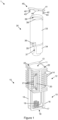
- Figures 1 to 9 show an embodiment of a housing unit for a load carrier (1) in accordance with the invention.
- the exploded view of Figure 1 shows the housing unit (1) having a sleeve (10) and a capsule (30) arranged to be secured within the sleeve (10) in a releasable manner as will be discussed further below.
- the sleeve (10) has a substantially rectangular cross-sectional profile, which corresponds to the shape of a cavity in a fin of an exemplary load carrier with which the housing unit (1) is to be used.
- the sleeve (10) defines a central chamber (11) extending longitudinally into the sleeve (10).
- the chamber (11) is surrounded by a first, ribbed section (12) immediately extending from an open end (13) of the chamber.
- the ribbed section (12) has spaced apart, parallel ribs (14) extending radially from the sleeve (10) and defines the generally rectangular cross-sectional shape of the sleeve.
- a second, exposed section (15) is provided at the longitudinal end opposite the ribbed section (12).
- the exposed section (15) mainly comprises two spaced apart and parallel wall sections (16).
- a transverse member (17) connects the two wall sections (16) and is provided at the end opposite the open end (13) of the chamber.
- the exposed section (15) is located at the operatively inner, blind end (18) of the chamber (11).
- the exposed section (15) therefore reveals a portion of the chamber toward the blind end (18) of the chamber (11).
- a spiral compression spring (19) is secured centrally in the chamber (11) against the transverse member (17) extending toward the open end (13) of the chamber, the functioning of which will be explained below.
- the sleeve (10) includes a pair of elongate gripper plates (20) extending radially from opposite sides of the sleeve, each gripper plate defines a row of barbs (21) spaced about an outermost edge of each gripper plate.
- the gripper plates (20) serve to increase the grip of the friction fit between the sleeve (10) and a load carrier when installed therein.
- the housing unit (1) furthermore includes a capsule (30), with a generally cylindrical shape.
- the capsule (30) has a hollow inner space defining a storage area (31) for holding an electronic device (32) and has two main parts which, for ease of reference, will be referred to as the holder section (33) and the cap section (34).
- Both sections (33, 34) have diametrically opposing tabs (35, 36) that align when the sections are assembled to form the closed capsule (30).
- the holder and cap sections (33, 34) are securable to each other by screwing the corresponding tabs (35, 36) on the respective sections together using screws (not shown).
- the cap section (34) is provided with an elongate recess (37) extending longitudinally in line with each tab (35) in the outside surface of the lower section to enable access to these screws with a screwdriver.
- the housing unit (1) further includes a tamper-evident tab (40) having an elongate cross-member (41), arranged to fit within the slot (39) in the holder section (33).
- the tamper-evident tab (40) further has two resiliently flexible clips (42) provided at each outer end thereof and extending substantially perpendicular from the cross-member (41) at rest. Each clip (42) has an outwardly angled hook (43).
- the tamper-evident tab (40) furthermore includes a magnet (44) provided on the cross-member (41), substantially centrally between the clips (42), the functionality of which is described further below.
- the electronic device (32) contained in the capsule (30) may have a magnetically sensitive component provided thereon that is arranged to detect the presence (or absence) of the magnet (44) on the tamper-evident tab (40). This may allow the electronic device (32) to log an event on local memory and/or send a distress signal to a remote server, indicating that a tamper event has taken place. By including information in the distress signal to uniquely identify the particular load carrier, and optionally its own latitude and longitude position, it may allow an operator to rapidly intervene.
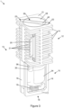
- FIGs 3 to 7 show the capsule (30) secured in the sleeve (10). Seen more clearly in Figure 3 and 6 , the tamper-evident tab (40) is also in its installed configuration. To install the tamper-evident tab (40), it is located in the slot (39) with the clips (42) extending toward the sleeve and is then pressed into the slot. In the installed configuration, the hooks (43) are arranged to hook onto a catch (not shown) provided in the sleeve (10) to keep the tamper-evident tab (40) in place.
- the capsule may be secured in the sleeve (10) and the tamper-evident tab (40) then installed in the capsule slot (39) as described above. Thereafter, the electronic device (32) may be configured to react to tamper events based on a detected magnetic field intensity. In this manner, the electronic device (32) may detect removal of the capsule (30) from the sleeve (10) by detecting a precursor or intermediate step to its removal, i.e. the removal of the tamper-evident tab (40).
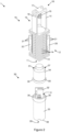
- the tabs (35, 36) of the capsule (30) perform a secondary role, in that they also form the male side of the bayonet mount that removably secures the capsule (30) to the sleeve (10).
- the sleeve (10) has corresponding diametrically opposing cut-outs or slots (22) at the opening of its chamber (11) and along its inner length that form the female part of the bayonet mount.
- the capsule tabs (35, 36) are aligned with the complementary shaped cut-outs (22) at the opening of the chamber (11) and the capsule (30) is then inserted into the chamber until the inserted end of the capsule abuts the spring (19) at the far end of the sleeve (10). At this point, the capsule (30) will be contained in the chamber (11), but with the outer, slotted end slightly protruding from the sleeve (10).
- the force of the spring (19) will push the capsule out of the sleeve (10) slightly, which enables an operator to easily grip the capsule for removal from the sleeve.
- the operator may be a human operator performing the securing of the capsule (30) in the sleeve (10) manually.
- assembly and servicing of the housing (1) and the electronic device (32) held in the capsule may be automated.
- the automation may be carried out by a robotic arm that is configured for this purpose, for example.
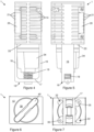
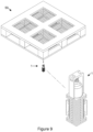
- Figure 8 shows the sleeve (10) installed in a load carrier (50). More particularly, it is received in a cavity (51) of the load carrier (50) with the exposed end (15) of the sleeve (10) extending into the relevant cavity (51).
- the exemplary load carrier shown in Figure 8 is a plastic pallet.
- the sleeve (10) may be used with any suitable load carrier having cavities defined in the body thereof, regardless of the dimensions of the cavities, with the housing unit (1) and thus the sleeve (10) being adapted accordingly.
- the ribbed section (12) is therefore positioned near the mouth (52) of the relevant cavity (51) with the open end (13) of the sleeve (10) being positioned substantially flush with the mouth (52) of the cavity (51).
- the sleeve (10) is installed in the cavity (51) by simply press-fitting it into the cavity (see also Figure 9 ).
- This particular embodiment of the housing unit (1) is adapted for the particular load carrier (50) so that the sleeve (10) forms a tight fit in the cavity (51).
- the barbs (21) bite into (or otherwise deform) the inner surface of the cavity (51) in which the sleeve is installed, resisting removal from the cavity.
- the gripper plates (20) extend radially from two opposing corners of the generally squarely profiled sleeve (10).
- the barbs (21) When installed in a load carrier (50), the barbs (21) will therefore extend into, and bite into, the corresponding inner corners of the relevant cavity (51). It will of course be appreciated that an adhesive may further be applied to the outer surface of the sleeve (10) to further increase the grip or bond with the load carrier (50).
- Figure 8 shows the open end (13) of the sleeve (10) to be flush with the mouth (52) of the cavity (51).
- the sleeve (10) may also be installed so as to be somewhat sunken into the cavity (51). This may ensure the stackability of the load carrier (50) on other load carriers for storage purposes, and may furthermore prevent damage and/or detection of the housing unit (1).
- bayonet-type mount is described in the one embodiment above for removably securing the capsule to the sleeve, it is conceivable that other mechanisms may be used, such as a screw thread arrangement.
- the bayonet mount arrangement may also be reversed, with projections provided in the chamber and corresponding slots provided in the capsule.
- the capsule may have quick-access apertures, optionally protected with ingress-protective plugs, to enable data exchange with the electronic monitoring device without requiring removal of the capsule from the sleeve.
- the embodiment depicted in the figures includes the pair of gripper plates, however it is envisaged that embodiments are possible that only use one gripper plate or where no gripper plates are necessary and the sleeve is simply press-fitted, glued or otherwise secured into the cavity in the load carrier. It will further be appreciated that the magnetically sensitive component provided on the electronic device contained in the capsule may alternatively be any suitable sensor for sensing the presence (or absence) of the tamper-evident tab which may comprise a suitable transmitter for that purpose.
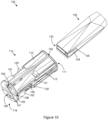
- FIGS 10 to 19 show a further embodiment of a housing unit (100) for a load carrier in accordance with the invention.
- the housing unit (100) has a sleeve (110) and a capsule (130) arranged to be secured within the sleeve (110) in a releasable manner as will be discussed further below.
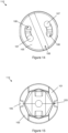
- the sleeve (110) has a substantially round or circular cross-sectional profile, which is shown more clearly in Figures 14 and 15 .
- a particular load carrier in which the housing unit (100) is to be used will therefore require a complementary shaped cross-section to enable the sleeve (110) to fitted therein.
- the sleeve (110) has a generally cylindrical overall shape.
- the sleeve (110) defines a central chamber (111) extending longitudinally into the sleeve (110) and has an open end (113) and an opposite blind end (118).
- the chamber (111) has longitudinally extending ribs (112) along an outer periphery immediately extending from an open end (113) of the chamber (111).
- the sleeve (110) includes a pair of diametrically opposed barb-like gripping structures (120) extending radially outwardly from opposite sides of the sleeve.
- the gripping structures (120) project from a tensile arm (121) extending longitudinally along an outer periphery of the sleeve and serve to increase the grip of the friction fit between the sleeve (110) and a load carrier when installed therein.
- the barb-like gripping structures (120) When the sleeve (110) is inserted into a cavity in a load carrier, the barb-like gripping structures (120) may press against the sides of the cavity and be urged radially inwardly against a bias of the tensile arms (121), thereby creating a radially outwardly directed force enhancing its grip within the cavity. It is also envisaged that the cavity in the load carrier into which the sleeve (110) is to be installed may have an indentation at a longitudinal position corresponding to that of the gripping structures (120). This may enable the barb-like gripping structures (120) to clip into these indentations when inserted into the cavity of the load carrier, thereby making the sleeve (110) resistant to removal from the load carrier.
- the sleeve (110) is constructed from two mirror image halves (101, 102).
- Figures 10 and 11 show a longitudinally extending joint line (103) where the two halves are joined.
- a substantially disk-shaped endcap (105) facilitates the joining of the two halves (101, 102) and has two diametrically opposed key-hole apertures (106) shaped to receive a corresponding bolt (107) provided on each half (101, 102) of the sleeve (110).
- the head of each bolt (107) is extended through the key-hole apertures (106) in the endcap (105) and the end-cap is rotated so that the head of each bolt locates at the narrow ends of the key-hole apertures.
- the end-cap (105) furthermore defines a diametrically extending slot (108) in an operatively outer surface thereof.
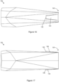
- the housing unit (100) also includes an elongate capsule (130) that is shaped and configured to be received in the sleeve (110).
- the capsule (130) has substantially flat longitudinal ends, and tapers towards an end (132) that is operatively inserted into the sleeve (110).
- the capsule (130) has a hollow inner space (not shown) defining a storage area for holding electronic components, batteries, and the like.
- a sloped tooth-like protrusion (134) is provided on opposite sides of the capsule (130) near the end (132) that is operatively inserted into the sleeve (110).
- Each tooth-like protrusion (134) slopes radially outwardly and terminates in a protruding edge (135). This forms the male part of the securing formation that operatively secures the capsule (130) within the sleeve (110).
- the sleeve (110) has two diametrically opposed spring-loaded catches (109) having an aperture shaped and configured to clip over the edge (135) of the corresponding tooth-like protrusion (134) of the capsule (130) when the capsule is inserted into the sleeve. This releasably secures the capsule (130) in the sleeve (110).
- the catches (109) form the female part of the securing formation that operatively secures the capsule (130) within the sleeve (110).
- a tool may be utilised to urge the catches a sufficient distance radially outwardly to clear the edge (135) of each tooth-like protrusion (134), allowing the capsule (130) to be extracted.
- a magnet may be located in the sleeve (110).
- an electronic device (not shown) contained in the capsule (130) may have a magnetically sensitive component provided thereon, such as a hall-effect sensor, that is arranged to detect the presence or absence of the magnet's magnetic field, corresponding to the presence or absence of the capsule (130) in the sleeve (110).
- the housing unit may be configured for a particular load carrier, for a range of load carriers, or at least for a load carrier having a particular cavity size.
- a load carrier may be supplied with the housing unit pre-installed or at least partially pre-installed in a load carrier.
- a particular load carrier (a pallet, say) may have a round or honeycomb-like structure for structural reinforcement.
- the housing unit may then have a round or hexagonal profile, as the case may be, to enable it to be received in the cavities of the particular load carrier.
- the overall length of the housing unit, and thus the sleeve and capsule may vary to adapt to different load carriers, but also to accommodate different electronic monitoring devices.
- an appropriate cavity may have to be machined into the load carrier, possibly as part of a method of retrofitting the load carrier with a housing unit (1, 100) as described above.
- Figure 20 illustrates the steps of a method (200) for retrofitting a load carrier with a housing unit.
- the load carrier may be machined (202) to create a cavity shaped to receive the sleeve (10, 110) therein in a friction fit.
- a sleeve with a substantially round cross-section may in some embodiments be more practical since the machining of a round cavity may be easier than a cavity with a square cross-section when retrofitting the load carrier with a housing unit (1, 100).
- a sleeve (10, 110) is provided (204) that is fitted (206) in the cavity of the load carrier.
- a capsule (30, 130) is provided (208) that is shaped and configured to be received in a chamber (11, 111) of the sleeve (10, 110).
- an electronic device may be commissioned and housed in the capsule (30, 130).
- the capsule (30, 130) is then inserted (210) into and received by the sleeve (10, 110), and corresponding male and female securing formations of the sleeve and capsule (30, 130), respectively, engage to releasably secure (212) the capsule in the sleeve.
- the invention disclosed herein therefore provides a secure, lightweight housing unit for a load carrier and enables electronic monitoring devices to be held therein, whilst still allowing regular authorised access to the electronics for replacement, repair or upgrade, as the case may be.
- the electronic monitoring device may be protected by the housing unit from liquid or dust ingress, protected from impact damage and may reduce detection of the device by nefarious individuals.
- no physical modification of may be required if the particular load carrier has pre-existing cavities in which the sleeve may fit.
- the relevant load carrier may be retrofitted with a housing unit after machining of a suitable cavity therein.
Landscapes
- Engineering & Computer Science (AREA)
- Mechanical Engineering (AREA)
- Casings For Electric Apparatus (AREA)
- Details Of Rigid Or Semi-Rigid Containers (AREA)
- Coupling Device And Connection With Printed Circuit (AREA)
- Pallets (AREA)
Claims (13)
- Gehäuseeinheit (1; 100), umfassend:eine Hülse (10; 110), die eine Kammer (11; 111) definiert, undeine Kapsel (30; 130), dazu angeordnet ist, eine elektronische Vorrichtung (32) darin aufzunehmen, wobei die Kapsel so geformt und ausgelegt ist, dass sie in der Kammer empfangen werden kann;wobei die Hülse und die Kapsel zusammenwirkende Befestigungsausbildungen (22, 35, 36; 109, 134) aufweisen, die so angeordnet sind, dass die Kapsel lösbar in der Kammer befestigt werden kann, undwobei die Hülse so geformt und ausgelegt ist, dass sie in einen Hohlraum in einem Lastträger (50) passen kann;dadurch gekennzeichnet, dass ein Ende der Kapsel einen Schlitz oder ein Schlüsselloch (39) aufweist, der/das darin definiert ist, um die Verwendung eines Werkzeugs oder Schlüssels zum Befestigen der Kapsel in der Kammer zu ermöglichen, und wobei der Schlitz oder das Schlüsselloch unter Verwendung eines Werkzeugs oder Schlüssels bedienbar ist, um entweder die Kapsel in der Hülse zu befestigen oder die Kapsel aus der Hülse zu lösen.
- Gehäuseeinheit gemäß Anspruch 1, wobei die Befestigungsausbildungen eine weibliche Befestigungsausbildung (22; 109) und eine komplementäre männliche Befestigungsausbildung (35, 36; 134) enthalten, die so ausgelegt sind, dass sie miteinander in Eingriff gebracht werden können, und wobei eine der männlichen und weiblichen Befestigungsausbildung der Hülse zugeordnet ist und die andere der Kapsel zugeordnet ist.
- Gehäuseeinheit gemäß Anspruch 2, wobei die männliche Befestigungsausbildung ein schräger, zahnartiger Vorsprung (134) ist und die weibliche Befestigungsausbildung eine federbelastete Verriegelung (109) mit einer Öffnung aufweist, die dazu eingerichtet ist, in eine Kante des zahnartigen Vorsprungs einzurasten, wenn die Kapsel in der Kammer empfangen wird.
- Gehäuseeinheit gemäß einem der vorhergehenden Ansprüche, wobei die Hülse eine Reibungspassung in dem Hohlraum in dem Lastträger (50) bildet, wobei die Hülse eine oder mehrere Greifstrukturen (20; 120) enthält, die dazu angeordnet sind, ihre Reibungspassung in dem Hohlraum des Lastträgers zu verbessern.
- Gehäuseeinheit gemäß Anspruch 4, wobei die Greifstrukturen Widerhaken (21) enthalten, die dazu angeordnet sind, das Entfernen der Hülse aus dem Hohlraum zu verhindern.
- Gehäuseeinheit gemäß einem der vorhergehenden Ansprüche, wobei ein äußeres Ende (38) der Kapsel (30) mit einem offenen Ende (13) der Kammer bündig ist, wenn sie darin befestigt ist.
- Gehäuseeinheit gemäß einem der vorhergehenden Ansprüche, die ferner einen Manipulationsanzeigemechanismus (40) enthält, der dazu eingerichtet ist, das Erkennen von einem oder beidem des Entfernens der Kapsel aus der Hülse und des Einsetzens der Kapsel in die Hülse zu ermöglichen.
- Gehäuseeinheit gemäß Anspruch 7, wobei der Manipulationsanzeigemechanismus (40) ein manipulationsanzeigendes Verriegelungselement enthält, das so angeordnet ist, dass es in dem Schlitz oder Schlüsselloch sitzt, der/das in dem äußeren Ende der Kapsel definiert ist.
- Gehäuseeinheit gemäß Anspruch 8, wobei das manipulationsanzeigende Verriegelungselement einen Magneten (44) enthält, um eine in der Kapsel gehaltene elektronische Vorrichtung in die Lage zu versetzen, die Entfernung des Verriegelungselements basierend auf einem erfassten Magnetfeld zu erkennen.
- Gehäuseeinheit gemäß Anspruch 7, wobei der Manipulationsanzeigemechanismus einen in der Hülse befindlichen Magneten enthält, der so angeordnet ist, dass ein in der Kapsel untergebrachter Sensor in der Lage ist, basierend auf einem erfassten Magnetfeld eines oder beides des Entfernens der Kapsel aus der Hülse und des Einsetzens der Kapsel in die Hülse zu erkennen.
- Gehäuseeinheit gemäß einem der vorhergehenden Ansprüche, die ferner eine Feder (19) enthält, die so angeordnet ist, dass sie die Kapsel mindestens teilweise unter ihrer Vorspannung aus der Kammer drückt, wenn die Befestigungsausbildung ausgerastet ist.
- Lastträger, der eine Gehäuseeinheit gemäß einem der Ansprüche 1 bis 11 enthält.
- Verfahren (200) zum Nachrüsten einer Gehäuseeinheit (1, 100) an einem Lastträger (50), wobei das Verfahren Folgendes beinhaltet:Bereitstellen (204) einer Hülse (10; 110), die eine Kammer (11; 111) definiert, wobei die Hülse so geformt und ausgelegt ist, dass sie in einen Hohlraum in einem Lastträger passt;Einsetzen (208) der Hülse in den Hohlraum des Lastträgers;Bereitstellen (206) einer Kapsel (30; 130), die so geformt und ausgelegt ist, dass sie in der Kammer aufgenommen werden kann, um eine elektronische Vorrichtung (32) in der Kapsel zu halten, wobei die Hülse und die Kapsel zusammenwirkende Befestigungsausbildungen aufweisen, die so angeordnet sind, dass die Kapsel lösbar in der Kammer befestigt werden kann; und Befestigen (210) der Kapsel in der Kammer;dadurch gekennzeichnet, dass das Verfahren die Verwendung eines Werkzeugs oder Schlüssels zur Bedienung eines in einem Ende der Kapsel definierten Schlitzes oder Schlüssellochs enthält, um entweder die Kapsel in der Hülse zu sichern oder die Kapsel aus der Hülse zu lösen.
Applications Claiming Priority (2)
| Application Number | Priority Date | Filing Date | Title |
|---|---|---|---|
| ZA201805723 | 2018-08-28 | ||
| PCT/IB2019/057255 WO2020044263A1 (en) | 2018-08-28 | 2019-08-28 | A housing unit for a load carrier |
Publications (4)
| Publication Number | Publication Date |
|---|---|
| EP3844075A1 EP3844075A1 (de) | 2021-07-07 |
| EP3844075A4 EP3844075A4 (de) | 2021-11-10 |
| EP3844075C0 EP3844075C0 (de) | 2024-04-10 |
| EP3844075B1 true EP3844075B1 (de) | 2024-04-10 |
Family
ID=69644092
Family Applications (1)
| Application Number | Title | Priority Date | Filing Date |
|---|---|---|---|
| EP19855555.9A Active EP3844075B1 (de) | 2018-08-28 | 2019-08-28 | Gehäuseeinheit für einen lastträger, lastträger und zugehöriges verfahren |
Country Status (9)
| Country | Link |
|---|---|
| US (1) | US11975888B2 (de) |
| EP (1) | EP3844075B1 (de) |
| JP (1) | JP2021535049A (de) |
| KR (1) | KR20210050542A (de) |
| CN (1) | CN112638783A (de) |
| AU (1) | AU2019331726A1 (de) |
| ES (1) | ES2982837T3 (de) |
| WO (1) | WO2020044263A1 (de) |
| ZA (1) | ZA202101845B (de) |
Families Citing this family (4)
| Publication number | Priority date | Publication date | Assignee | Title |
|---|---|---|---|---|
| JP7509870B2 (ja) * | 2019-11-06 | 2024-07-02 | シーエイチイーピー テクノロジー ピーティーワイ リミテッド | パレット |
| US11530074B2 (en) * | 2020-05-20 | 2022-12-20 | Noble House Home Furnishing, LLC | Material handling pallet |
| WO2023044258A1 (en) * | 2021-09-14 | 2023-03-23 | Quantronix, Inc. | Apparatus and methods for pallet load monitoring |
| DE102023205300B4 (de) | 2023-06-06 | 2025-01-02 | Volkswagen Aktiengesellschaft | Ladungsträger mit Magnetverschluss |
Family Cites Families (18)
| Publication number | Priority date | Publication date | Assignee | Title |
|---|---|---|---|---|
| KR100207673B1 (ko) * | 1996-04-24 | 1999-07-15 | 윤종용 | 디스크플레이어 |
| JP2002037414A (ja) | 2000-07-21 | 2002-02-06 | Mitsubishi Materials Corp | Rfidタグによる製品及びその購入者の情報管理方法 |
| JP4068832B2 (ja) | 2001-07-17 | 2008-03-26 | 日本パレットレンタル株式会社 | 識別タグ付きパレット |
| JP3456649B1 (ja) * | 2002-05-29 | 2003-10-14 | 勝美 永吉 | ロールペーパー供給装置 |
| JP4425618B2 (ja) | 2003-12-08 | 2010-03-03 | 吉田プラ工業株式会社 | ノック式スライドケース |
| US7948381B2 (en) * | 2004-04-30 | 2011-05-24 | Binforma Group Limited Liability Company | Reversibly deactivating a radio frequency identification data tag |
| ITBS20040070A1 (it) | 2004-06-01 | 2004-09-01 | Gualdi S R L | Pedana per motociclette, in particolare per motociclette da fuoristrada |
| WO2005118368A2 (de) * | 2004-06-02 | 2005-12-15 | Toni Dick | Ladungsträger |
| NZ534456A (en) * | 2005-01-29 | 2007-09-28 | Pallenz Plastics Ltd | Protective housing for wireless identification tag with coupling means releasably coupled and at least partially surrounded by portable storage device (typically a pallet) |
| CN2936951Y (zh) * | 2006-06-19 | 2007-08-22 | 浙江中烟工业公司 | 电子托盘 |
| JP4868447B2 (ja) | 2006-08-23 | 2012-02-01 | 三甲株式会社 | パレット |
| US9262905B2 (en) * | 2011-04-27 | 2016-02-16 | Gojo Industries, Inc. | Portable compliance dispenser |
| KR101207673B1 (ko) | 2011-07-29 | 2012-12-03 | (주) 네톰 | 팔레트용 rfid 태그 홀더 및 이를 가지는 팔레트 |
| JP2013237455A (ja) * | 2012-05-11 | 2013-11-28 | Japan Pallet Rental Corp | パレット用識別器およびパレット |
| JP2015224048A (ja) | 2014-05-27 | 2015-12-14 | ユーピーアール株式会社 | タグホルダー及びパレット |
| EP3240200A1 (de) * | 2016-04-26 | 2017-11-01 | Novartis Ag | Behälteranordnung mit einer drahtloskommunikationsvorrichtung und verfahren zum betrieb davon |
| JP2018047932A (ja) | 2016-09-23 | 2018-03-29 | マイクロテクノロジー株式会社 | 端末カバー、端末装置及びパレット |
| CN206719758U (zh) * | 2017-05-08 | 2017-12-08 | 山东贝福特新材料有限公司 | 一种安全多功能智能托盘系统 |
-
2019
- 2019-08-28 EP EP19855555.9A patent/EP3844075B1/de active Active
- 2019-08-28 KR KR1020217008898A patent/KR20210050542A/ko not_active Ceased
- 2019-08-28 CN CN201980057141.8A patent/CN112638783A/zh active Pending
- 2019-08-28 JP JP2021536431A patent/JP2021535049A/ja active Pending
- 2019-08-28 ES ES19855555T patent/ES2982837T3/es active Active
- 2019-08-28 AU AU2019331726A patent/AU2019331726A1/en not_active Abandoned
- 2019-08-28 US US17/271,681 patent/US11975888B2/en active Active
- 2019-08-28 WO PCT/IB2019/057255 patent/WO2020044263A1/en not_active Ceased
-
2021
- 2021-03-18 ZA ZA2021/01845A patent/ZA202101845B/en unknown
Also Published As
| Publication number | Publication date |
|---|---|
| CN112638783A (zh) | 2021-04-09 |
| EP3844075A4 (de) | 2021-11-10 |
| ZA202101845B (en) | 2024-08-28 |
| AU2019331726A1 (en) | 2021-04-29 |
| US11975888B2 (en) | 2024-05-07 |
| US20210188482A1 (en) | 2021-06-24 |
| EP3844075C0 (de) | 2024-04-10 |
| WO2020044263A1 (en) | 2020-03-05 |
| EP3844075A1 (de) | 2021-07-07 |
| KR20210050542A (ko) | 2021-05-07 |
| ES2982837T3 (es) | 2024-10-17 |
| JP2021535049A (ja) | 2021-12-16 |
Similar Documents
| Publication | Publication Date | Title |
|---|---|---|
| EP3844075B1 (de) | Gehäuseeinheit für einen lastträger, lastträger und zugehöriges verfahren | |
| US7828342B2 (en) | Reusable locking body, of bolt-type seal lock, having open-ended passageway and U-shaped bolt | |
| US7382262B2 (en) | System and method of tamper detection | |
| EP1171330B1 (de) | Elektronisches sicherheitssiegel | |
| US10119301B2 (en) | Tamper evident cargo container seal bolt lock | |
| US20140130609A1 (en) | Thread clamping device including internal sensing, reporting and external detector | |
| JP6990311B6 (ja) | 物流器具とその解体防止方法 | |
| US20190367320A1 (en) | Traceable Cable Drum and Kit for Traceable Cable Drum | |
| KR102175301B1 (ko) | 도난 방지 기능을 갖는 물품 위치 추적 장치 | |
| US20060164231A1 (en) | Cargo container integrity system | |
| HK40047012A (en) | A housing unit for a load carrier | |
| US20140377034A1 (en) | Security seal fastener system | |
| KR100997692B1 (ko) | 아이디태그가 구비된 물품운반용 팔레트 | |
| WO2009098670A2 (en) | Tamper evident seal | |
| EP1717773B1 (de) | System und Verfahren zur Manipulationsdetektion | |
| RU41904U1 (ru) | Устройство для объединения электронной метки с механическим запорно-пломбировочным устройством | |
| US10607126B2 (en) | Asset tracker utilizing thread protector | |
| CN213653520U (zh) | 电子标识器防拆装置及电子标识器系统 | |
| US11565877B2 (en) | Container closure node system | |
| KR20090093300A (ko) | 물품운반용 팔레트의 아이디태그 | |
| KR20090093741A (ko) | 물품운반용 팔레트의 아이디태그 | |
| WO2021015666A1 (en) | Electronic bolt seal | |
| HK1092922A1 (en) | A seal |
Legal Events
| Date | Code | Title | Description |
|---|---|---|---|
| STAA | Information on the status of an ep patent application or granted ep patent |
Free format text: STATUS: THE INTERNATIONAL PUBLICATION HAS BEEN MADE |
|
| STAA | Information on the status of an ep patent application or granted ep patent |
Free format text: STATUS: REQUEST FOR EXAMINATION WAS MADE |
|
| PUAI | Public reference made under article 153(3) epc to a published international application that has entered the european phase |
Free format text: ORIGINAL CODE: 0009012 |
|
| 17P | Request for examination filed |
Effective date: 20210326 |
|
| AK | Designated contracting states |
Kind code of ref document: A1 Designated state(s): AL AT BE BG CH CY CZ DE DK EE ES FI FR GB GR HR HU IE IS IT LI LT LU LV MC MK MT NL NO PL PT RO RS SE SI SK SM TR |
|
| A4 | Supplementary search report drawn up and despatched |
Effective date: 20211008 |
|
| RIC1 | Information provided on ipc code assigned before grant |
Ipc: B65D 19/38 20060101AFI20211004BHEP |
|
| DAV | Request for validation of the european patent (deleted) | ||
| DAX | Request for extension of the european patent (deleted) | ||
| STAA | Information on the status of an ep patent application or granted ep patent |
Free format text: STATUS: EXAMINATION IS IN PROGRESS |
|
| 17Q | First examination report despatched |
Effective date: 20230213 |
|
| GRAP | Despatch of communication of intention to grant a patent |
Free format text: ORIGINAL CODE: EPIDOSNIGR1 |
|
| STAA | Information on the status of an ep patent application or granted ep patent |
Free format text: STATUS: GRANT OF PATENT IS INTENDED |
|
| INTG | Intention to grant announced |
Effective date: 20231103 |
|
| GRAS | Grant fee paid |
Free format text: ORIGINAL CODE: EPIDOSNIGR3 |
|
| GRAA | (expected) grant |
Free format text: ORIGINAL CODE: 0009210 |
|
| STAA | Information on the status of an ep patent application or granted ep patent |
Free format text: STATUS: THE PATENT HAS BEEN GRANTED |
|
| AK | Designated contracting states |
Kind code of ref document: B1 Designated state(s): AL AT BE BG CH CY CZ DE DK EE ES FI FR GB GR HR HU IE IS IT LI LT LU LV MC MK MT NL NO PL PT RO RS SE SI SK SM TR |
|
| REG | Reference to a national code |
Ref country code: GB Ref legal event code: FG4D |
|
| REG | Reference to a national code |
Ref country code: CH Ref legal event code: EP |
|
| REG | Reference to a national code |
Ref country code: DE Ref legal event code: R096 Ref document number: 602019050193 Country of ref document: DE |
|
| REG | Reference to a national code |
Ref country code: IE Ref legal event code: FG4D |
|
| U01 | Request for unitary effect filed |
Effective date: 20240510 |
|
| U07 | Unitary effect registered |
Designated state(s): AT BE BG DE DK EE FI FR IT LT LU LV MT NL PT SE SI Effective date: 20240521 |
|
| U20 | Renewal fee for the european patent with unitary effect paid |
Year of fee payment: 6 Effective date: 20240827 |
|
| PG25 | Lapsed in a contracting state [announced via postgrant information from national office to epo] |
Ref country code: IS Free format text: LAPSE BECAUSE OF FAILURE TO SUBMIT A TRANSLATION OF THE DESCRIPTION OR TO PAY THE FEE WITHIN THE PRESCRIBED TIME-LIMIT Effective date: 20240810 |
|
| PG25 | Lapsed in a contracting state [announced via postgrant information from national office to epo] |
Ref country code: HR Free format text: LAPSE BECAUSE OF FAILURE TO SUBMIT A TRANSLATION OF THE DESCRIPTION OR TO PAY THE FEE WITHIN THE PRESCRIBED TIME-LIMIT Effective date: 20240410 |
|
| PG25 | Lapsed in a contracting state [announced via postgrant information from national office to epo] |
Ref country code: GR Free format text: LAPSE BECAUSE OF FAILURE TO SUBMIT A TRANSLATION OF THE DESCRIPTION OR TO PAY THE FEE WITHIN THE PRESCRIBED TIME-LIMIT Effective date: 20240711 |
|
| REG | Reference to a national code |
Ref country code: ES Ref legal event code: FG2A Ref document number: 2982837 Country of ref document: ES Kind code of ref document: T3 Effective date: 20241017 |
|
| PG25 | Lapsed in a contracting state [announced via postgrant information from national office to epo] |
Ref country code: PL Free format text: LAPSE BECAUSE OF FAILURE TO SUBMIT A TRANSLATION OF THE DESCRIPTION OR TO PAY THE FEE WITHIN THE PRESCRIBED TIME-LIMIT Effective date: 20240410 |
|
| PG25 | Lapsed in a contracting state [announced via postgrant information from national office to epo] |
Ref country code: PL Free format text: LAPSE BECAUSE OF FAILURE TO SUBMIT A TRANSLATION OF THE DESCRIPTION OR TO PAY THE FEE WITHIN THE PRESCRIBED TIME-LIMIT Effective date: 20240410 Ref country code: NO Free format text: LAPSE BECAUSE OF FAILURE TO SUBMIT A TRANSLATION OF THE DESCRIPTION OR TO PAY THE FEE WITHIN THE PRESCRIBED TIME-LIMIT Effective date: 20240710 Ref country code: IS Free format text: LAPSE BECAUSE OF FAILURE TO SUBMIT A TRANSLATION OF THE DESCRIPTION OR TO PAY THE FEE WITHIN THE PRESCRIBED TIME-LIMIT Effective date: 20240810 Ref country code: HR Free format text: LAPSE BECAUSE OF FAILURE TO SUBMIT A TRANSLATION OF THE DESCRIPTION OR TO PAY THE FEE WITHIN THE PRESCRIBED TIME-LIMIT Effective date: 20240410 Ref country code: GR Free format text: LAPSE BECAUSE OF FAILURE TO SUBMIT A TRANSLATION OF THE DESCRIPTION OR TO PAY THE FEE WITHIN THE PRESCRIBED TIME-LIMIT Effective date: 20240711 Ref country code: RS Free format text: LAPSE BECAUSE OF FAILURE TO SUBMIT A TRANSLATION OF THE DESCRIPTION OR TO PAY THE FEE WITHIN THE PRESCRIBED TIME-LIMIT Effective date: 20240710 |
|
| REG | Reference to a national code |
Ref country code: DE Ref legal event code: R097 Ref document number: 602019050193 Country of ref document: DE |
|
| PG25 | Lapsed in a contracting state [announced via postgrant information from national office to epo] |
Ref country code: CZ Free format text: LAPSE BECAUSE OF FAILURE TO SUBMIT A TRANSLATION OF THE DESCRIPTION OR TO PAY THE FEE WITHIN THE PRESCRIBED TIME-LIMIT Effective date: 20240410 |
|
| PG25 | Lapsed in a contracting state [announced via postgrant information from national office to epo] |
Ref country code: RO Free format text: LAPSE BECAUSE OF FAILURE TO SUBMIT A TRANSLATION OF THE DESCRIPTION OR TO PAY THE FEE WITHIN THE PRESCRIBED TIME-LIMIT Effective date: 20240410 Ref country code: SK Free format text: LAPSE BECAUSE OF FAILURE TO SUBMIT A TRANSLATION OF THE DESCRIPTION OR TO PAY THE FEE WITHIN THE PRESCRIBED TIME-LIMIT Effective date: 20240410 |
|
| PG25 | Lapsed in a contracting state [announced via postgrant information from national office to epo] |
Ref country code: SM Free format text: LAPSE BECAUSE OF FAILURE TO SUBMIT A TRANSLATION OF THE DESCRIPTION OR TO PAY THE FEE WITHIN THE PRESCRIBED TIME-LIMIT Effective date: 20240410 |
|
| PG25 | Lapsed in a contracting state [announced via postgrant information from national office to epo] |
Ref country code: SM Free format text: LAPSE BECAUSE OF FAILURE TO SUBMIT A TRANSLATION OF THE DESCRIPTION OR TO PAY THE FEE WITHIN THE PRESCRIBED TIME-LIMIT Effective date: 20240410 Ref country code: SK Free format text: LAPSE BECAUSE OF FAILURE TO SUBMIT A TRANSLATION OF THE DESCRIPTION OR TO PAY THE FEE WITHIN THE PRESCRIBED TIME-LIMIT Effective date: 20240410 Ref country code: RO Free format text: LAPSE BECAUSE OF FAILURE TO SUBMIT A TRANSLATION OF THE DESCRIPTION OR TO PAY THE FEE WITHIN THE PRESCRIBED TIME-LIMIT Effective date: 20240410 Ref country code: CZ Free format text: LAPSE BECAUSE OF FAILURE TO SUBMIT A TRANSLATION OF THE DESCRIPTION OR TO PAY THE FEE WITHIN THE PRESCRIBED TIME-LIMIT Effective date: 20240410 |
|
| PLBE | No opposition filed within time limit |
Free format text: ORIGINAL CODE: 0009261 |
|
| STAA | Information on the status of an ep patent application or granted ep patent |
Free format text: STATUS: NO OPPOSITION FILED WITHIN TIME LIMIT |
|
| 26N | No opposition filed |
Effective date: 20250113 |
|
| PG25 | Lapsed in a contracting state [announced via postgrant information from national office to epo] |
Ref country code: MC Free format text: LAPSE BECAUSE OF FAILURE TO SUBMIT A TRANSLATION OF THE DESCRIPTION OR TO PAY THE FEE WITHIN THE PRESCRIBED TIME-LIMIT Effective date: 20240410 |
|
| U20 | Renewal fee for the european patent with unitary effect paid |
Year of fee payment: 7 Effective date: 20250901 |
|
| PGFP | Annual fee paid to national office [announced via postgrant information from national office to epo] |
Ref country code: ES Payment date: 20250909 Year of fee payment: 7 |
|
| PGFP | Annual fee paid to national office [announced via postgrant information from national office to epo] |
Ref country code: GB Payment date: 20250828 Year of fee payment: 7 |
|
| PGFP | Annual fee paid to national office [announced via postgrant information from national office to epo] |
Ref country code: CH Payment date: 20250901 Year of fee payment: 7 |
|
| PGFP | Annual fee paid to national office [announced via postgrant information from national office to epo] |
Ref country code: IE Payment date: 20250828 Year of fee payment: 7 |
|
| PG25 | Lapsed in a contracting state [announced via postgrant information from national office to epo] |
Ref country code: CY Free format text: LAPSE BECAUSE OF FAILURE TO SUBMIT A TRANSLATION OF THE DESCRIPTION OR TO PAY THE FEE WITHIN THE PRESCRIBED TIME-LIMIT; INVALID AB INITIO Effective date: 20190828 |
|
| PG25 | Lapsed in a contracting state [announced via postgrant information from national office to epo] |
Ref country code: HU Free format text: LAPSE BECAUSE OF FAILURE TO SUBMIT A TRANSLATION OF THE DESCRIPTION OR TO PAY THE FEE WITHIN THE PRESCRIBED TIME-LIMIT; INVALID AB INITIO Effective date: 20190828 |