EP3843929B1 - Gassteuersystem und verfahren für einen reflow-lötofen - Google Patents
Gassteuersystem und verfahren für einen reflow-lötofen Download PDFInfo
- Publication number
- EP3843929B1 EP3843929B1 EP19770224.4A EP19770224A EP3843929B1 EP 3843929 B1 EP3843929 B1 EP 3843929B1 EP 19770224 A EP19770224 A EP 19770224A EP 3843929 B1 EP3843929 B1 EP 3843929B1
- Authority
- EP
- European Patent Office
- Prior art keywords
- intake valve
- set value
- gas
- oxygen concentration
- valve device
- Prior art date
- Legal status (The legal status is an assumption and is not a legal conclusion. Google has not performed a legal analysis and makes no representation as to the accuracy of the status listed.)
- Active
Links
Images



Classifications
-
- B—PERFORMING OPERATIONS; TRANSPORTING
- B23—MACHINE TOOLS; METAL-WORKING NOT OTHERWISE PROVIDED FOR
- B23K—SOLDERING OR UNSOLDERING; WELDING; CLADDING OR PLATING BY SOLDERING OR WELDING; CUTTING BY APPLYING HEAT LOCALLY, e.g. FLAME CUTTING; WORKING BY LASER BEAM
- B23K1/00—Soldering, e.g. brazing, or unsoldering
- B23K1/0008—Soldering, e.g. brazing, or unsoldering specially adapted for particular articles or work
- B23K1/0016—Soldering of electronic components
-
- B—PERFORMING OPERATIONS; TRANSPORTING
- B23—MACHINE TOOLS; METAL-WORKING NOT OTHERWISE PROVIDED FOR
- B23K—SOLDERING OR UNSOLDERING; WELDING; CLADDING OR PLATING BY SOLDERING OR WELDING; CUTTING BY APPLYING HEAT LOCALLY, e.g. FLAME CUTTING; WORKING BY LASER BEAM
- B23K1/00—Soldering, e.g. brazing, or unsoldering
- B23K1/008—Soldering within a furnace
-
- B—PERFORMING OPERATIONS; TRANSPORTING
- B23—MACHINE TOOLS; METAL-WORKING NOT OTHERWISE PROVIDED FOR
- B23K—SOLDERING OR UNSOLDERING; WELDING; CLADDING OR PLATING BY SOLDERING OR WELDING; CUTTING BY APPLYING HEAT LOCALLY, e.g. FLAME CUTTING; WORKING BY LASER BEAM
- B23K3/00—Tools, devices or special appurtenances for soldering, e.g. brazing, or unsoldering, not specially adapted for particular methods
- B23K3/08—Auxiliary devices therefor
-
- B—PERFORMING OPERATIONS; TRANSPORTING
- B23—MACHINE TOOLS; METAL-WORKING NOT OTHERWISE PROVIDED FOR
- B23K—SOLDERING OR UNSOLDERING; WELDING; CLADDING OR PLATING BY SOLDERING OR WELDING; CUTTING BY APPLYING HEAT LOCALLY, e.g. FLAME CUTTING; WORKING BY LASER BEAM
- B23K35/00—Rods, electrodes, materials, or media, for use in soldering, welding, or cutting
- B23K35/22—Rods, electrodes, materials, or media, for use in soldering, welding, or cutting characterised by the composition or nature of the material
- B23K35/38—Selection of media, e.g. special atmospheres for surrounding the working area
- B23K35/383—Selection of media, e.g. special atmospheres for surrounding the working area mainly containing noble gases or nitrogen
-
- G—PHYSICS
- G05—CONTROLLING; REGULATING
- G05D—SYSTEMS FOR CONTROLLING OR REGULATING NON-ELECTRIC VARIABLES
- G05D27/00—Simultaneous control of variables covered by two or more of main groups G05D1/00 - G05D25/00
- G05D27/02—Simultaneous control of variables covered by two or more of main groups G05D1/00 - G05D25/00 characterised by the use of electric means
-
- B—PERFORMING OPERATIONS; TRANSPORTING
- B23—MACHINE TOOLS; METAL-WORKING NOT OTHERWISE PROVIDED FOR
- B23K—SOLDERING OR UNSOLDERING; WELDING; CLADDING OR PLATING BY SOLDERING OR WELDING; CUTTING BY APPLYING HEAT LOCALLY, e.g. FLAME CUTTING; WORKING BY LASER BEAM
- B23K2101/00—Articles made by soldering, welding or cutting
- B23K2101/36—Electric or electronic devices
- B23K2101/42—Printed circuits
Definitions
- the present application relates to a reflow soldering furnace, in particular to a gas control system and method for a reflow soldering furnace (see for example JPH08172263 A ).
- EP 1847828A1 discloses a method and apparatus for controlling a brazing process using a tunable diode laser to measure the concentration of contaminants, and calculating values for process parameters used to control aspects of the brazing process.
- WO 2014/090571A1 discloses a portable equipment for monitoring and controlling the level of residual oxygen in a reflow oven atmosphere.
- a soldering paste for example, a tin paste, is deposited in a selected area on a circuit board, and the conducting wires of one or more electronic components are inserted into the deposited soldering paste.
- circuit board is passed through a reflow soldering furnace.
- the soldering paste is caused to reflow in a heating zone (that is, for being heated to fusion or a reflow temperature) and is then cooled in a cooling zone, thereby electrically and mechanically connecting the electronic components to the circuit board.
- a heating zone that is, for being heated to fusion or a reflow temperature
- a cooling zone thereby electrically and mechanically connecting the electronic components to the circuit board.
- circuit board used herein includes a basal plate element of an electronic component of any type, for example, a wafer basal plate.
- a reflow soldering furnace air or a basically inert gas, for example, nitrogen, is generally used as a working gas.
- air or a basically inert gas for example, nitrogen
- different working gases are used.
- the furnace chamber of a reflow soldering furnace is filled with a working gas, and soldering is performed in the working gas when a circuit board is conveyed into the furnace chamber by a conveying device.
- a reflow soldering furnace that uses a basically inert gas as a working gas, external air inevitably enters the furnace chamber of the reflow soldering furnace when the furnace is working, consequently generating oxygen in the furnace chamber.
- oxygen concentration reaches or exceeds a certain level, soldering will be affected adversely; for example, a soldered component may be oxidized. Therefore, it is necessary to, when a reflow soldering furnace is working, maintain a desired oxygen concentration by supplying additional working gas to the furnace chamber.
- the present application provides a gas control system and method for a reflow soldering furnace, in which an oxygen concentration in a furnace chamber is detected in real time, and a gas control valve is automatically regulated on the basis of a predetermined set value or target value to control input of a working gas, thereby ensuring that a concentration of the working gas in the furnace chamber meets the requirements of the soldering process.
- a gas control system and method according to the present application precise control and fast regulation is achieved; in addition, when work is stopped or during work intermissions, a gas control valve can be closed in a timely manner, thereby preventing waste and reducing costs.
- FIG. 1 is a schematic diagram for an embodiment of a reflow soldering furnace and a gas control system therefor according to the present application, showing a view taken from a lateral face of the reflow soldering furnace.
- the reflow soldering furnace 110 comprises a furnace chamber 112, a preheating zone 101, a soaking zone 103, a peak value zone 105, and a cooling zone 107. Between the peak value zone 105 and the cooling zone 107, a baffle exhaust zone 109 is further disposed.
- the furnace chamber 112 passes through the preheating zone 101, the soaking zone 103, the peak value zone 105, and the cooling zone 107, and the preheating zone 101, the soaking zone 103, the peak value zone 105, and the cooling zone 107 are in fluid communication via the furnace chamber 112. Further, each of the preheating zone 101, the soaking zone 103, the peak value zone 105, and the cooling zone 107 is also in fluid communication with the furnace chamber 112.
- the furnace chamber 112 comprises an inlet 114 and an outlet 116.
- the reflow soldering furnace 110 further comprises a conveying device 118, the conveying device 118 being disposed passing through the furnace chamber 112 and configured to convey a circuit board to be processed into the furnace chamber 112 via the inlet 114 of the furnace chamber 112 and convey a circuit board processed by the reflow soldering furnace 110 out of the furnace chamber 112 via the outlet 116 of the furnace chamber 112.
- the reflow soldering furnace 110 may use an inert gas, for example, nitrogen, as a working gas. An explanation will be given below using nitrogen as a working gas.
- Figure 1 shows a view taken from a lateral face of the reflow soldering furnace 110, wherein for convenience of explanation of the reflow soldering furnace 110, a casing for sheltering from the front and rear of the furnace chamber 112 is omitted in Figure 1 .
- a heating device is disposed in the preheating zone 101, the soaking zone 103, and the peak value zone 105, respectively, and these zones jointly form a heating zone 106.
- the heating zone 106 comprises three preheating zones 101, three soaking zones 103, and three peak value zones 105.
- the preheating zones 101, the soaking zones 103, and the peak value zones 105 are successively connected, in which the temperature rises gradually.
- a circuit board is heated, and part of the flux in the soldering paste allocated to the circuit board will be vaporized.
- the peak value zone 105 has a higher temperature than the preheating zone 101 or the soaking zone 103, and the soldering paste is melted in the peak value zone 105.
- the peak value zone 105 is also the zone in which a VOC having a higher temperature, for example, rosin or resin, will be vaporized.
- the reflow soldering furnace 110 comprises three cooling zones 107, and a cooling device is disposed in each of these zones. After a circuit board is conveyed from the heating zone 106 into the cooling zone 107, the soldering paste is cooled and solidified in the soldering area of the circuit board, thereby connecting an electronic component to the circuit board.
- the numbers of the preheating zones 101, the soaking zones 103, the peak value zones 105, and the cooling zones 107 may be changed according to the products to be soldered and different soldering processes, instead of being limited to the embodiment shown in Figure 1 .
- a baffle exhaust zone 109 is disposed in a connecting area between the heating zone 106 and the cooling zone 107.
- the baffle exhaust zone 109 may draw out or discharge a gas from the furnace chamber 112, thereby blocking or reducing gas containing a volatile contaminant that enters the cooling zone 107 from the heating zone 106.
- the baffle exhaust zone 109 may also be used as a thermal insulation zone that separates the high-temperature heating zone 106 and the low-temperature cooling zone 107.
- the reflow soldering furnace 110 may use nitrogen as a working gas.
- the reflow soldering furnace 110 is provided with a working gas source 140, for supplying a clean working gas to the furnace chamber 112.
- the reflow soldering furnace 110 further comprises a gas baffle zone 108 located at the inlet 114 and the outlet 116 of the furnace chamber 112.
- the gas baffle zone 108 is configured to supply nitrogen to the furnace chamber 112, thereby forming a nitrogen curtain, and the nitrogen curtain can prevent air in the external environment from entering the furnace chamber 112.
- the reflow soldering furnace 110 is further provided with a gas discharge device (not shown in the figure), for discharging the gas containing a volatile contaminant in the furnace chamber 112.
- a gas discharge device is generally connected to a high-temperature zone of the reflow soldering furnace 110, for example, the soaking zone 103, the peak value zone 105, or the baffle exhaust zone 109.
- the gas discharge device keeps working so that the gas in the furnace chamber 112 remains clean. In this process, it is also necessary to keep inputting clean nitrogen from the working gas source 140, thereby maintaining a working atmosphere and working pressure required by the furnace chamber 112.
- the working gas in the furnace chamber 112 always contains oxygen.
- Different soldering processes require different oxygen concentrations in the furnace chamber 112, generally in a range of 500 to 5000 parts per million (PPM). It is hoped that an oxygen concentration in the furnace chamber 112 remains around a value required by a specific soldering process. Thus, the requirement on soldering quality is met, while nitrogen is saved.
- the reflow soldering furnace 110 is further provided with a gas control system, for regulating an oxygen concentration in the furnace chamber 112 by regulating the amount of nitrogen supplied to the furnace chamber 112, so that the oxygen concentration reaches a level required by a specific soldering process in a reflow soldering furnace.
- said gas control system is further configured to, based on a working state of the reflow soldering furnace 110, control start and stop of the working gas source 140.
- a gas control system for the reflow soldering furnace 110 comprises an oxygen detecting device 120, a first intake valve device 131, a second intake valve device 132, and a controller 122.
- the oxygen detecting device 120 in contact with a gas in the furnace chamber 112, is configured to detect an oxygen concentration in the furnace chamber 112 and generate an oxygen concentration signal based on the detected oxygen concentration.
- the first intake valve device 131 and the second intake valve device 132 are configured to controllably establish fluid communication between the working gas source 140 and the furnace chamber 112, thereby inputting nitrogen into the furnace chamber 112.
- the controller 122 is configured to, based on an oxygen concentration signal, control the opening extent of the first intake valve device 131 and that of the second intake valve device 132 to regulate the amount of nitrogen supplied to the furnace chamber 112, thereby regulating the oxygen concentration in the furnace chamber 112.
- Said opening extent indicates an extent of valve opening, in a range of 0% to 100%, wherein 0% indicates that the valve is closed and 100% indicates that the valve is fully open.
- Said oxygen concentration signal reflects an actual detection value DV of an oxygen concentration.
- the first intake valve device 131 and the second intake valve device 132 each comprise a pressure-proportioning valve and a throttling valve.
- the first intake valve device 131 comprises a first pressure-proportioning valve 133.1 and a first throttling valve 134.1
- the second intake valve device 132 comprises a second pressure-proportioning valve 133.2 and a second throttling valve 134.2.
- the first pressure-proportioning valve 133.1 and the second pressure-proportioning valve 133.2 are connected to the working gas source 140 to controllably regulate the pressure of nitrogen received from the working gas source 140.
- the first throttling valve 134.1 and the second throttling valve 134.2 are connected to the first pressure-proportioning valve 133.1 and the second pressure-proportioning valve 133.2, respectively, to linearly regulate a gas flow speed based on gas pressure regulated by the first pressure-proportioning valve 133.1 and the second pressure-proportioning valve 133.2.
- the first pressure-proportioning valve 133.1 and the second pressure-proportioning valve 133.2 may regulate gas pressure within a range of 0 MPa to 1 MPa; correspondingly, the first throttling valve 134.1 and the second throttling valve 134.2 may linearly regulate a gas flow speed based on gas pressure within a range of 0 m3/hour to 18 m3/hour.
- the first pressure-proportioning valve 133.1 and the second pressure-proportioning valve 133.2 are connected to the controller 122, so that the opening extent of the first pressure-proportioning valve 133.1 and that of the second pressure-proportioning valve 133.2 can be controlled by the controller 122, while the first throttling valve 134.1 and the second throttling valve 134.2 can automatically regulate a gas flow speed respectively based on gas pressure regulated by the first pressure-proportioning valve 133.1 and the second pressure-proportioning valve 133.2.
- the flow speed of the gas is regulated by a combination of pressure-proportioning valves and throttling valves to reach a desired gas flow speed while creating desired gas pressure.
- a specific oxygen concentration target set value TV is preset and is stored in the controller 122.
- the controller 122 can identify said target set value TV, compare an actual detection value DV reflected by an oxygen concentration signal generated by the oxygen detecting device 120 with a preset target set value TV, and, based on a comparison result, control the opening extent of the first pressure-proportioning valve 133.1 and that of the second pressure-proportioning valve 133.2. If the actual detection value DV is greater than the preset target set value TV, it indicates that the oxygen concentration is too high while the nitrogen concentration is too low and that therefore the nitrogen input needs to be increased; otherwise, the nitrogen input needs to be decreased.
- the first intake valve device 131 establishes fluid communication between the preheating zone 101 and the working gas source 140
- the second intake valve device 132 establishes fluid communication between the cooling zone 107 and the working gas source 140;
- gas temperatures gradually increase from left to right, and different gas temperatures are required in different areas to meet different soldering process requirements.
- Nitrogen is supplied to the furnace chamber 112 from a position of the preheating zone 101 near the inlet 114 and the cooling zone 107 near the outlet 116, so that room-temperature nitrogen from the working gas source 140 enters an area having a lower temperature, thereby preventing any significant impact on the gas temperature in an area having a higher temperature.
- the gas control system comprises a working state indicating device 150, for indicating whether the reflow soldering furnace 110 is in a state of processing a circuit board or in a state of not processing any circuit board.
- a working state indicating device 150 for indicating whether the reflow soldering furnace 110 is in a state of processing a circuit board or in a state of not processing any circuit board.
- the reflow soldering furnace 110 starts/stops processing a circuit board. For example, when the reflow soldering furnace 110 is started/stopped, a state indication signal indicating a start/stop is sent to the working state indicating device 150. Alternatively, when the reflow soldering furnace 110 is in a work intermission, for example, when no circuit board is being processed in the furnace chamber 112, a relevant sensor or detecting device sends a corresponding state indication signal to the working state indicating device 150.
- the controller 122 closes the first intake valve device 131 and the second intake valve device 132 to stop nitrogen supply in a timely manner.
- the working state indicating device 150 may be a D trigger or an RS trigger, capable of outputting different state signals (such as a high level and a low level) to indicate different states of the reflow soldering furnace 110 (for example, a high level indicates that the furnace is working and a low level indicates that the furnace is stopped, or a low level indicates that the furnace is working and a high level indicates that the furnace is stopped).
- the D trigger or RS trigger may be controlled by the control panel 151; on the control panel 151, the ON and OFF control keys may set the output of the D trigger or RS trigger to a high level or a low level, for indicating different working states.
- the oxygen detecting device 120 comes into contact with a gas in the peak value zone 105, for detecting an oxygen concentration in the peak value zone 105.
- the peak value zone 105 has the highest temperature and is an area that has a significant impact on soldering quality in the process of soldering. Therefore, in the present application, an oxygen concentration in the peak value zone 105 is detected and a nitrogen supply amount is regulated on the basis of the detected oxygen concentration in the peak value zone 105, so that the oxygen concentration in the peak value zone 105 is kept at a target set value required by the soldering process, thereby significantly improving the soldering quality.
- Figures 2A and 2B respectively show schematic diagrams for two different embodiments of the gas control system shown in Figure 1 , wherein the embodiments shown in Figures 2A and 2B comprise different oxygen detecting devices 120.
- the oxygen detecting device 120 comprises a sampling device 220 and an oxygen analyzer 222.
- the sampling device 220 in fluid communication with the furnace chamber 112, is configured to collect a gas in the furnace chamber 112.
- the oxygen analyzer 222 is connected to the sampling device 220 and configured to analyze an oxygen concentration in the gas collected the sampling device 220, thereby obtaining an actual detection value DV of the oxygen concentration.
- the oxygen analyzer 222 is further connected to the controller 122 and configured to transfer the actual detection value DV of the oxygen concentration obtained by an analysis to the controller 122.
- the gas may be filtered to prevent any volatile contaminant contained in the gas in the furnace chamber 112 from affecting the normal operation of the oxygen analyzer 222, thereby improving the analytic precision of the oxygen analyzer 222 and prolonging the service life of the oxygen analyzer 222.
- the oxygen detecting device 120 comprises an oxygen probe 221 and a transmission device 223.
- the oxygen probe 221 is inserted into the furnace chamber 112, and is configured to detect an oxygen concentration in the furnace chamber 112 and generate an oxygen concentration signal.
- the transmission device 223 is connected to the oxygen probe 221, and is configured to transmit an oxygen concentration detected by the oxygen probe 221 to the controller 122.
- a gas contact surface is provided at the front end of the oxygen probe 221, allowing an oxygen concentration of a gas to be detected by coming into contact with the gas.
- the front end of the oxygen probe 221 is inserted into the furnace chamber 112 for detection, achieving fast detection and high detection precision; in addition, since no additional air duct needs to be installed, production and use is convenient.
- the transmission device 223 may convert an oxygen concentration signal detected by the oxygen probe 221 to a format suitable for reception and processing by the controller 122, for example, the RS485 format, and then transmit the signal to the controller 122.
- the transmission device 223 may be a standalone device, or may be integrated with the oxygen probe 221. In another embodiment, the transmission device 223 may also be integrated with the controller 122.
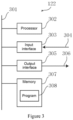
- FIG 3 is a schematic diagram for an embodiment of the controller 122 shown in Figure 1 .
- the controller 122 comprises a bus 301, a processor 302, an input interface 303, an output interface 305, and a memory 307 storing a control program 308.
- the processor 302, the input interface 303, the output interface 305, and the memory 307 are connected for communication via the bus 301, allowing the processor 302 to control the operation of the input interface 303, the output interface 305, and the memory 307.
- the memory 307 is configured to store a program, an instruction, and data
- the processor 302 is configured to read a program, an instruction, and data from the memory 307, capable of writing data to the memory 307.
- the input interface 303 receives, via a connection 304, a signal and data, for example, a signal sent by the working state indicating device 150 that indicates a working state of the reflow soldering furnace 110, an oxygen concentration signal sent by the oxygen detecting device 120, and various manually input parameters.
- the output interface 305 sends, via a connection 306, a signal and data, for example, sending a control signal for regulating an opening extent to intake valve devices 131 and 132.
- the memory 307 stores a control program, a preset target set value and a regulation set value of an oxygen concentration, and other data. Various parameters may be preset in the engineering during manufacture, or various parameters may be set by manual input or data import.
- the processor 302 receives, through the interface 303 and the memory 307, various signals, data, programs, and instructions, processes them accordingly, and then produces output through the interface 305.
- Figure 4 is flowchart of a nitrogen input control method for the reflow soldering furnace and a gas control system therefor shown in Figure 1 , showing an embodiment of a method for controlling nitrogen input when the nitrogen input needs to be increased because the actual detection value DV of the oxygen concentration is much greater than the target set value TV.
- the corresponding regulation set value RV of an oxygen concentration is further preset according to different soldering process requirements and is stored in the memory 307 of the controller 122.
- the regulation set value RV is greater than said target set value TV.
- opening extent V1 of the first pressure-proportioning valve 133.1 and opening extent V2 of the second pressure-proportioning valve 133.2 are both regulated; in the fine regulation process, only the second pressure-proportioning valve 133.2 closer to the oxygen detection zone (namely, the peak value zone 105) is selected for regulation, while opening extent V1 of the first pressure-proportioning valve 133.1 is kept at a preset value.
- a corresponding preset value of V1 may be set on the basis of the target set value TV. For example, when the target set value TV is 500 PPM, the preset value of V1 is set to 35%; when the target set value TV is 1000 PPM, the preset value of V1 is set to 30%.
- the actual detection value DV of the oxygen concentration is much greater than the target set value TV, the following steps are performed:
- Step 402 is a rough regulation process, in which nitrogen input can be significantly increased by concurrently increasing the opening extents of the pressure-proportioning valves 133.1 and 133.2, thereby decreasing the oxygen concentration rapidly.
- Steps 403 to 408 the fine regulation process is performed, in which opening extent V1 of the first pressure-proportioning valve 133.1 is kept at a preset value, while only opening extent V2 of the second pressure-proportioning valve 133.2 is regulated; thus, nitrogen input can be regulated stably so that the actual detection value DV can gradually approach and be stabilized at the target set value TV, thereby ensuring that a desired oxygen concentration is reached while saving nitrogen.
- the second pressure-proportioning valve 133.2 can be finely regulated so that the actual detection value DV is stabilized at the target set value TV or fluctuates only slightly around the target set value TV.
- a circuit board can be processed in a working atmosphere having a relatively stable concentration, which improves the process precision and processing effect; on the other hand, nitrogen can be saved and energy consumption reduced effectively.
- the nitrogen input control method shown in Figure 4 is only one embodiment of the present application.
- Those of ordinary skill in the art may alter the control method for nitrogen input based on specific configurations of a gas control system. For example, in the fine regulation process, opening extent of the second pressure-proportioning valve 133.2 is kept at a preset value, while only opening extent of the first pressure-proportioning valve 133.1 is regulated; any such alterations fall into the protection scope of the present application.
Landscapes
- Engineering & Computer Science (AREA)
- Mechanical Engineering (AREA)
- Physics & Mathematics (AREA)
- General Physics & Mathematics (AREA)
- Automation & Control Theory (AREA)
- Electric Connection Of Electric Components To Printed Circuits (AREA)
- Waste-Gas Treatment And Other Accessory Devices For Furnaces (AREA)
- Furnace Details (AREA)
- Tunnel Furnaces (AREA)
Claims (11)
- Gassteuersystem für einen Reflow-Lötofen (110), wobei eine Ofenkammer (112) des Reflow-Lötofens (110) eine Vorheizzone (101) und eine Kühlzone (107) aufweist und ein Gas enthält, wobei das Gas Sauerstoff und ein Arbeitsgas aufweist, wobei eine Arbeitsumgebung der Ofenkammer (112) eine einen Zielsollwert (Tv) erreichende Sauerstoffkonzentration erfordert, wobei das Gassteuersystem aufweist:
eine Sauerstoffdetektionsvorrichtung (120), wobei die Sauerstoffdetektionsvorrichtung (120) im Betrieb in der Lage ist, mit dem Gas in der Ofenkammer (112) in Kontakt zu kommen, zum Detektieren einer Sauerstoffkonzentration in der Ofenkammer (112), wobei die Sauerstoffdetektionsvorrichtung (120) ein Sauerstoffkonzentrationssignal basierend auf der detektierten Sauerstoffkonzentration erzeugt, dadurch gekennzeichnet, dass das Gassteuersystem ferner aufweist:mindestens eine erste Einlassventilvorrichtung (131) und eine zweite Einlassventilvorrichtung (132), wobei die erste Einlassventilvorrichtung (131) konfiguriert ist, im Betrieb eine steuerbare Fluidverbindung zwischen der Vorheizzone (101) und einer Arbeitsgasquelle (140) herzustellen, und die zweite Einlassventilvorrichtung (132) konfiguriert ist, eine steuerbare Fluidverbindung zwischen der Kühlzone (107) und der Arbeitsgasquelle (140) herzustellen, wodurch das Arbeitsgas in die Ofenkammer (112) eingeleitet wird; undeine Steuerung (122), wobei die Steuerung (122) konfiguriert ist, das Öffnungsmaß der ersten Einlassventilvorrichtung (131) und der zweiten Einlassventilvorrichtung (132) basierend auf dem Sauerstoffkonzentrationssignal zu steuern, wodurch eine Flussrate des in die Ofenkammer (112) eingeleiteten Arbeitsgases reguliert wird, wobei die Steuerung (122) einen Speicher (307) aufweist, der konfiguriert ist, einen Regulierungssollwert (Rv) und den Zielsollwert (Tv) einer Sauerstoffkonzentration zu speichern, wobei der Regulierungssollwert (Rv) größer als der Zielsollwert (Tv) ist;und ferner dadurch gekennzeichnet, dass die Steuerung (122) konfiguriert ist zum:wenn ein durch das Sauerstoffkonzentrationssignal widergespiegelter Ist-Detektionswert (Dv) größer als der Regulierungssollwert (Rv) ist, Erhöhen des Öffnungsmaßes der ersten Einlassventilvorrichtung (131) und der zweiten Einlassventilvorrichtung (132), bis der Ist-Detektionswert (Dv) kleiner als der Regulierungssollwert (Rv) ist; undwenn ein durch das Sauerstoffkonzentrationssignal widergespiegelter Ist-Detektionswert (Dv) kleiner als der Regulierungssollwert (Rv) und der Ist-Detektionswert (Dv) größer als der Zielsollwert (Tv) ist, Beibehalten des Öffnungsmaßes der ersten Einlassventilvorrichtung (131) auf einem vorgegebenen Wert und Verringern des Öffnungsmaßes der zweiten Einlassventilvorrichtung (132), bis der Ist-Detektionswert (Dv) gleich dem Zielsollwert (Tv) ist. - Gassteuersystem nach Anspruch 1,
dadurch gekennzeichnet, dassdie Ofenkammer (112) eine Spitzenwertzone (105) aufweist, die konfiguriert ist, bei der höchsten Temperatur innerhalb der Ofenkammer (112) zu arbeiten; unddie Sauerstoffdetektionsvorrichtung (120) mit einem Gas in der Spitzenwertzone (105) in Kontakt kommt, um eine Sauerstoffkonzentration in der Spitzenwertzone (105) zu detektieren. - Gassteuersystem nach Anspruch 1, dadurch gekennzeichnet, dass es ferner eine Arbeitszustandsanzeigevorrichtung (150) zum Anzeigen, ob sich der Reflow-Lötofen (110) in einem Zustand der Verarbeitung einer Leiterplatte oder in einem Zustand der Nichtverarbeitung einer Leiterplatte befindet, aufweist;
wobei, wenn die Arbeitszustandsanzeigevorrichtung (150) anzeigt, dass sich der Reflow-Lötofen (110) in einem Zustand der Nichtverarbeitung einer Leiterplatte befindet, die Steuerung (122) konfiguriert ist, die mindestens erste Einlassventilvorrichtung (131) und die zweite Einlassventilvorrichtung (132) zu veranlassen, ein Arbeitsgas zu der niedrigsten Flussrate auszugeben und bereitzustellen. - Gassteuersystem nach Anspruch 1, dadurch gekennzeichnet, dass die Sauerstoffdetektionsvorrichtung (120) aufweist:eine Probenahmevorrichtung (220), wobei die Probenahmevorrichtung (220) in Fluidverbindung mit der Ofenkammer (112) steht, um ein Gas in der Ofenkammer (112) zu sammeln;einen Sauerstoffanalysator (222), wobei der Sauerstoffanalysator (222) mit der Probenahmevorrichtung (220) verbunden ist, um eine Sauerstoffkonzentration in dem gesammelten Gas zu analysieren; undder Sauerstoffanalysator (222) mit der Steuerung (122) verbunden ist, um das Sauerstoffkonzentrationssignal basierend auf einer Sauerstoffkonzentration, die durch eine Analyse mit dem Sauerstoffanalysator (222) erhalten wird, zu erzeugen und das Sauerstoffkonzentrationssignal an die Steuerung (122) zu übertragen.
- Gassteuersystem nach Anspruch 1, dadurch gekennzeichnet, dass die Sauerstoffdetektionsvorrichtung (120) aufweist:eine Sauerstoffsonde (221), wobei die Sauerstoffsonde (221) in die Ofenkammer (112) eingeführt wird, um eine Sauerstoffkonzentration in der Ofenkammer (112) zu detektieren; unddie Sauerstoffsonde (221) mit der Steuerung (122) verbunden ist, um das Sauerstoffkonzentrationssignal basierend auf einer von der Sauerstoffsonde (221) detektierten Sauerstoffkonzentration zu erzeugen und das Sauerstoffkonzentrationssignal an die Steuerung (122) zu übertragen.
- Gassteuersystem nach Anspruch 1, dadurch gekennzeichnet, dass jede der mindestens ersten Einlassventilvorrichtung (131) und der zweiten Einlassventilvorrichtung (132) aufweist:ein Druckdosierungsventil (133.1, 133.2), wobei das Druckdosierungsventil (133.1, 133.2) mit der Arbeitsgasquelle (140) verbunden ist, um ein Arbeitsgas von der Arbeitsgasquelle (140) aufzunehmen, wobei das Druckdosierungsventil (133.1, 133.2) mit der Steuerung (122) verbunden ist, um den Gasdruck gemäß dem Steuern durch die Steuerung (122) zu regulieren; undein Drosselventil (134.1, 134.2), wobei das Drosselventil (134.1, 134.2) mit dem Druckdosierungsventil (133.1, 133.2) verbunden ist, um eine Gasströmungsgeschwindigkeit basierend auf dem durch das Druckdosierungsventil (133.1, 133.2) regulierten Gasdruck linear zu regulieren.
- Gassteuersystem nach einem der Ansprüche 1 bis 6, dadurch gekennzeichnet, dass das Arbeitsgas Stickstoff ist.
- Gassteuerverfahren für einen Reflow-Lötofen (110), dadurch gekennzeichnet, dass eine Ofenkammer (112) des Reflow-Lötofens (110) eine Vorheizzone (101) und eine Kühlzone (107) aufweist, wobei eine Arbeitsumgebung der Ofenkammer (112) eine einen Zielsollwert (Tv) erreichende Sauerstoffkonzentration erfordert, wobei das Gassteuerverfahren die folgenden Schritte umfasst:Detektieren einer Sauerstoffkonzentration in der Ofenkammer (112), wobei die detektierte Sauerstoffkonzentration einen Ist-Detektionswert (Dv) widerspiegelt;Festlegen eines Regulierungssollwerts (Rv) und des Zielsollwerts (Tv), wobei der Regulierungssollwert (Rv) größer als der Zielsollwert (Tv) ist;wenn der Ist-Detektionswert (Dv) größer als der Regulierungssollwert (Rv) ist, Erhöhen des Öffnungsmaßes einer ersten Einlassventilvorrichtung (131) und des Öffnungsmaßes einer zweiten Einlassventilvorrichtung (132), bis der Ist-Detektionswert (Dv) kleiner als der Regulierungssollwert (Rv) ist, wobei die erste Einlassventilvorrichtung (131) eine Fluidverbindung zwischen der Vorheizzone (101) und der Arbeitsgasquelle (140) herstellt, und die zweite Einlassventilvorrichtung (132) eine Fluidverbindung zwischen der Kühlzone (107) und der Arbeitsgasquelle (140) herstellt; undwenn der Ist-Detektionswert (Dv) kleiner als der Regulierungssollwert (Rv) ist und der Ist-Detektionswert (Dv) größer als der Zielsollwert (Tv) ist, Beibehalten des Öffnungsmaßes der ersten Einlassventilvorrichtung (131) auf einem vorgegebenen Wert und Verringern des Öffnungsmaßes der zweiten Einlassventilvorrichtung (132), bis der Ist-Detektionswert (Dv) gleich dem Zielsollwert (Tv) ist.
- Gassteuerverfahren nach Anspruch 8, dadurch gekennzeichnet, dass es ferner die folgenden Schritte aufweist:wenn der Reflow-Lötofen (110) eine Arbeitsatmosphäre mit einer relativ stabilen Konzentration aufweist, Beibehalten des Öffnungsmaßes der ersten Einlassventilvorrichtung (131) auf einem vorgegebenen Wert und Regulieren des Öffnungsmaßes der zweiten Einlassventilvorrichtung (132), wodurch der Ist-Detektionswert (Dv) in ungefährer Höhe des Zielsollwerts (Tv) stabilisiert wird;wobei, wenn der Ist-Detektionswert (Dv) kleiner als der Zielsollwert (Tv) ist, das Öffnungsmaß der zweiten Einlassventilvorrichtung (132) verringert wird, bis der Ist-Detektionswert (Dv) gleich dem Zielsollwert (Tv) ist;wenn der Ist-Detektionswert (Dv) größer als der Zielsollwert (Tv) ist, das Öffnungsmaß der zweiten Einlassventilvorrichtung (132) erhöht wird, bis der Ist-Detektionswert (Dv) gleich dem Zielsollwert (Tv) ist; undwenn der Ist-Detektionswert (Dv) gleich dem Zielsollwert (Tv) ist, das Öffnungsmaß der zweiten Einlassventilvorrichtung (132) auf einem gegenwärtigen Wert beibehalten wird.
- Gassteuerverfahren nach Anspruch 8, dadurch gekennzeichnet, dassdie Ofenkammer (112) ferner eine Spitzenwertzone (105) aufweist, die konfiguriert ist, bei der höchsten Temperatur innerhalb der Ofenkammer (112) zu arbeiten; undeine Sauerstoffkonzentration in der Ofenkammer (112) aufweist: eine Sauerstoffkonzentration in der Spitzenwertzone (105).
- Gassteuerverfahren nach Anspruch 8, dadurch gekennzeichnet, dass es ferner die folgenden Schritte aufweist:Detektieren eines Arbeitszustands des Reflow-Lötofens (110); undwenn detektiert wird, dass sich der Reflow-Lötofen (110) nicht in einem Arbeitszustand befindet, Verringern des Öffnungsmaßes der ersten Einlassventilvorrichtung (131) und des Öffnungsmaßes der zweiten Einlassventileinrichtung (132), um ein Arbeitsgas zu der niedrigsten Flussrate auszugeben und bereitzustellen.
Applications Claiming Priority (2)
| Application Number | Priority Date | Filing Date | Title |
|---|---|---|---|
| CN201811013268.3A CN110874106B (zh) | 2018-08-31 | 2018-08-31 | 用于回流焊炉的气体控制系统和方法 |
| PCT/US2019/049113 WO2020047442A1 (en) | 2018-08-31 | 2019-08-30 | Gas control system and method for a reflow soldering furnace |
Publications (2)
| Publication Number | Publication Date |
|---|---|
| EP3843929A1 EP3843929A1 (de) | 2021-07-07 |
| EP3843929B1 true EP3843929B1 (de) | 2025-01-15 |
Family
ID=67997689
Family Applications (1)
| Application Number | Title | Priority Date | Filing Date |
|---|---|---|---|
| EP19770224.4A Active EP3843929B1 (de) | 2018-08-31 | 2019-08-30 | Gassteuersystem und verfahren für einen reflow-lötofen |
Country Status (6)
| Country | Link |
|---|---|
| US (2) | US12325089B2 (de) |
| EP (1) | EP3843929B1 (de) |
| JP (1) | JP7470100B2 (de) |
| CN (1) | CN110874106B (de) |
| TW (1) | TWI793351B (de) |
| WO (1) | WO2020047442A1 (de) |
Families Citing this family (11)
| Publication number | Priority date | Publication date | Assignee | Title |
|---|---|---|---|---|
| CN110385496B (zh) * | 2018-04-20 | 2022-09-30 | 伊利诺斯工具制品有限公司 | 回流焊炉及其操作方法 |
| CN110871299A (zh) * | 2018-08-29 | 2020-03-10 | 伊利诺斯工具制品有限公司 | 回流焊炉的降温系统 |
| CN112935450B (zh) * | 2019-12-10 | 2025-10-31 | 伊利诺斯工具制品有限公司 | 回流焊炉 |
| CN111805046A (zh) * | 2020-07-09 | 2020-10-23 | 武汉倍普科技有限公司 | 一种回流炉的氧气控制系统 |
| CN112379700A (zh) * | 2020-09-25 | 2021-02-19 | 苏州浪潮智能科技有限公司 | 一种回流焊氮气流量控制方法、设备及存储介质 |
| CN114985861A (zh) * | 2021-03-01 | 2022-09-02 | 伊利诺斯工具制品有限公司 | 氧含量检测系统及其控制方法 |
| US11862482B2 (en) | 2021-03-11 | 2024-01-02 | Taiwan Semiconductor Manufacturing Company, Ltd. | Semiconductor substrate bonding tool and methods of operation |
| CN115383240A (zh) * | 2021-05-24 | 2022-11-25 | 伊利诺斯工具制品有限公司 | 用于回流焊炉的气体控制系统及回流焊炉 |
| CN117066634A (zh) * | 2022-05-09 | 2023-11-17 | 伊利诺斯工具制品有限公司 | 氧气检测系统及使用该氧气检测系统的回流焊炉 |
| CN115430895A (zh) * | 2022-10-08 | 2022-12-06 | 广东辰威机器人有限公司 | 焊接保护气体自动节能装置、方法及焊接机器人 |
| CN115790148B (zh) * | 2022-11-03 | 2026-01-13 | 湖北融通高科先进材料集团股份有限公司 | 一种磷酸铁锂辊道窑的自动排气方法及其自动排气设备 |
Family Cites Families (41)
| Publication number | Priority date | Publication date | Assignee | Title |
|---|---|---|---|---|
| GB561408A (en) * | 1942-01-10 | 1944-05-18 | Western Electric Co | Improved heat-treating apparatus |
| JPH052521Y2 (de) * | 1985-07-06 | 1993-01-21 | ||
| JPH03101296A (ja) * | 1989-09-14 | 1991-04-26 | Fujitsu Ltd | プリント基板の半田付け用リフロー炉の構造 |
| JP3420283B2 (ja) * | 1993-06-07 | 2003-06-23 | 株式会社タムラ製作所 | 不活性雰囲気はんだ付け装置における酸素濃度制御方法およびその装置 |
| JP2842203B2 (ja) * | 1994-01-25 | 1998-12-24 | 松下電器産業株式会社 | チッソリフロー装置 |
| JP3563791B2 (ja) * | 1994-12-16 | 2004-09-08 | 株式会社タムラ製作所 | 不活性雰囲気リフロー炉用の酸素濃度自動制御装置 |
| FR2757650B1 (fr) * | 1996-12-20 | 1999-01-15 | Air Liquide | Procede d'alimentation en gaz d'une enceinte et methode de regulation de la teneur en un element donne de l'atmosphere d'une telle enceinte |
| JPH11340618A (ja) * | 1998-05-25 | 1999-12-10 | Fujitsu Ten Ltd | 半田付け装置の酸素濃度制御装置 |
| JP3684307B2 (ja) | 1998-10-19 | 2005-08-17 | シーケーディ株式会社 | ガス供給制御装置 |
| MXPA03004561A (es) * | 2000-11-22 | 2003-09-10 | Avl List Gmbh | Metodo para suministrar un motor de comubstion interna con gas de combustion acondicionado, dispositivo para llevar a cabo dicho metodo, metodo para determinar la cantidad de contaminantes en los gase agotados en un motor de combustion interna y disp |
| US6780225B2 (en) * | 2002-05-24 | 2004-08-24 | Vitronics Soltec, Inc. | Reflow oven gas management system and method |
| JP2005226609A (ja) | 2004-02-16 | 2005-08-25 | Matsushita Electric Ind Co Ltd | 軸流機械の動翼角度可変装置 |
| JP5117703B2 (ja) | 2005-10-19 | 2013-01-16 | 株式会社タムラ製作所 | はんだ付け装置における雰囲気形成方法と雰囲気形成装置 |
| US20070246512A1 (en) * | 2006-04-20 | 2007-10-25 | Shahabudin Kazi | Use of tunable diode lasers for controlling a brazing processes |
| CN101058123A (zh) * | 2006-04-20 | 2007-10-24 | 乔治洛德方法研究和开发液化空气有限公司 | 可调谐二极管激光器用于控制钎焊工艺的用途 |
| PL4368229T3 (pl) * | 2008-05-27 | 2026-05-04 | Fisher & Paykel Healthcare Limited | Sterowanie temperaturą komory nawilżacza w celu dokładnego sterowania wilgotnością |
| CN201293946Y (zh) * | 2008-09-23 | 2009-08-19 | 熊猫电子集团有限公司 | 氮气闭环控制系统 |
| JP5233903B2 (ja) * | 2009-08-17 | 2013-07-10 | 千住金属工業株式会社 | はんだ付け用雰囲気ガス測定装置 |
| US8560213B2 (en) * | 2009-09-03 | 2013-10-15 | Toyota Jidosha Kabushiki Kaisha | Exhaust gas recirculation device of engine |
| CN101881463A (zh) * | 2009-12-28 | 2010-11-10 | 中冶南方工程技术有限公司 | 热风炉自动寻优燃烧智能控制方法 |
| CN102375458A (zh) * | 2010-08-12 | 2012-03-14 | 鸿富锦精密工业(深圳)有限公司 | 货柜数据中心及其氧气浓度调节装置 |
| CN102266630B (zh) * | 2010-12-31 | 2014-10-01 | 北京谊安医疗系统股份有限公司 | 一种呼吸机气体比例控制方法及装置 |
| JP5077475B1 (ja) | 2011-11-02 | 2012-11-21 | オムロン株式会社 | 加熱炉、その制御装置、その制御プログラム、および、その制御方法 |
| BR102012032031A2 (pt) * | 2012-12-14 | 2014-09-09 | Air Liquide Brasil Ltda | Equipamento portátil para monitoramento e controle do nível de oxigênio em atmosfera de fornos de refusão |
| JP6336707B2 (ja) * | 2013-02-14 | 2018-06-06 | 株式会社タムラ製作所 | リフロー装置 |
| CN104423405B (zh) * | 2013-09-11 | 2017-01-11 | 湖南华望熏蒸消毒有限公司 | 一种氮气气调控制系统及方法 |
| CN103861489B (zh) * | 2014-03-27 | 2016-01-20 | 上海海事大学 | 内燃机配气系统气体混合系统及气体混合方法 |
| CN105674570A (zh) * | 2014-11-19 | 2016-06-15 | 天津佳成宝自动化科技有限公司 | 模糊pid式仿生锅炉节能控制系统 |
| CN204474325U (zh) * | 2015-03-12 | 2015-07-15 | 肖永初 | 一种闭环系统制氧机及其流量/浓度调节闭环控制系统 |
| KR102121260B1 (ko) | 2015-12-25 | 2020-06-10 | 가부시키가이샤 후지킨 | 유량 제어 장치 및 유량 제어 장치를 사용하는 이상 검지 방법 |
| CN205309503U (zh) * | 2016-01-12 | 2016-06-15 | 深圳市大创自动化设备有限公司 | 一种回流焊炉的氮气供给系统 |
| CN205309492U (zh) * | 2016-01-12 | 2016-06-15 | 深圳市大创自动化设备有限公司 | 一种回流焊炉 |
| CN105772887B (zh) * | 2016-05-06 | 2018-02-27 | 东莞市科隆威自动化设备有限公司 | 一种多功能回流焊装置及其控制方法 |
| CN205834426U (zh) * | 2016-07-05 | 2016-12-28 | 依工电子设备(苏州)有限公司 | 回流焊炉的氧气控制系统 |
| CN206270689U (zh) * | 2016-09-26 | 2017-06-20 | 东莞市邰正节能科技有限公司 | 回焊炉供氮智能控制系统 |
| CN206316504U (zh) * | 2016-12-14 | 2017-07-11 | 苏州世伍克机电设备有限公司 | 回流焊炉流量节能装置 |
| CN106695048A (zh) * | 2016-12-21 | 2017-05-24 | 通富微电子股份有限公司 | 一种回流焊炉及其控制系统 |
| CN106970187A (zh) * | 2017-06-01 | 2017-07-21 | 上海昶艾电子科技有限公司 | 波峰焊/回流焊炉的氧气浓度检测系统及控制方法 |
| CN107120200B (zh) * | 2017-06-26 | 2023-06-20 | 山东大学 | 燃气压力-尾气氧含量双闭环进气控制系统及控制方法 |
| CN107366550A (zh) * | 2017-07-13 | 2017-11-21 | 中国矿业大学 | 一种矿井避难硐室氧气高效利用方法 |
| CN207289104U (zh) * | 2017-08-22 | 2018-05-01 | 伊利诺斯工具制品有限公司 | 一种回流焊炉 |
-
2018
- 2018-08-31 CN CN201811013268.3A patent/CN110874106B/zh active Active
-
2019
- 2019-07-18 TW TW108125430A patent/TWI793351B/zh active
- 2019-08-30 JP JP2021510656A patent/JP7470100B2/ja active Active
- 2019-08-30 WO PCT/US2019/049113 patent/WO2020047442A1/en not_active Ceased
- 2019-08-30 US US17/271,465 patent/US12325089B2/en active Active
- 2019-08-30 EP EP19770224.4A patent/EP3843929B1/de active Active
-
2025
- 2025-05-14 US US19/208,173 patent/US20250269452A1/en active Pending
Also Published As
| Publication number | Publication date |
|---|---|
| TW202010588A (zh) | 2020-03-16 |
| CN110874106A (zh) | 2020-03-10 |
| TWI793351B (zh) | 2023-02-21 |
| WO2020047442A1 (en) | 2020-03-05 |
| US20210339330A1 (en) | 2021-11-04 |
| JP7470100B2 (ja) | 2024-04-17 |
| US20250269452A1 (en) | 2025-08-28 |
| CN110874106B (zh) | 2022-09-02 |
| EP3843929A1 (de) | 2021-07-07 |
| US12325089B2 (en) | 2025-06-10 |
| JP2021536365A (ja) | 2021-12-27 |
Similar Documents
| Publication | Publication Date | Title |
|---|---|---|
| US20250269452A1 (en) | Gas control system and method for a reflow soldering furnace | |
| US20240230232A1 (en) | Gas control system for reflow furnace and reflow furnace | |
| EP2317309B1 (de) | Gaschromatographvorrichtung | |
| US20160256946A1 (en) | Soldering Apparatus and Vacuum-Soldering Method | |
| EP2932809B1 (de) | Tragbare ausrüstung zur überwachung und steuerung des sauerstoffpegels in einer rückflussofenatmosphäre | |
| US12013185B2 (en) | Reflow furnace | |
| CN111805038A (zh) | 一种离线正压焊接炉系统及其操作方法 | |
| US4672271A (en) | Apparatus and method for automatic operation of a high pressure mercury arc lamp | |
| KR20110120444A (ko) | 열풍로 설비의 연소 제어 장치 및 방법 | |
| US5795147A (en) | Furnace having regulated flow rate of inerting gas | |
| KR101659671B1 (ko) | 리워크 시스템 | |
| CN210306248U (zh) | 激光切割气路控制装置及系统 | |
| TWI915510B (zh) | 氧含量檢測系統及其控制方法 | |
| EP0778453A1 (de) | Ofen mit Zuführung von Schutzgas zu den Einlass- und/oder Auslassquerschnitten | |
| CN207521845U (zh) | 锡焊枪 | |
| KR100250504B1 (ko) | 열 교환기 자동 온도조절장치 및 그 제어방법 | |
| CN117270592A (zh) | 金属3d打印压力及气氛动态控制系统及其方法 | |
| CN213686233U (zh) | 一种氮气智能控制装置 | |
| US12543272B2 (en) | Reflow oven | |
| CN221337006U (zh) | 一种焊接装置 | |
| JPH11340618A (ja) | 半田付け装置の酸素濃度制御装置 | |
| JPH03101296A (ja) | プリント基板の半田付け用リフロー炉の構造 | |
| JP2007133613A (ja) | 圧力制御装置 | |
| CN118328703A (zh) | 氧气含量监控一体检测仪及回流炉 | |
| JP2002249820A (ja) | 加熱炉の炉温制御方法 |
Legal Events
| Date | Code | Title | Description |
|---|---|---|---|
| STAA | Information on the status of an ep patent application or granted ep patent |
Free format text: STATUS: UNKNOWN |
|
| STAA | Information on the status of an ep patent application or granted ep patent |
Free format text: STATUS: THE INTERNATIONAL PUBLICATION HAS BEEN MADE |
|
| STAA | Information on the status of an ep patent application or granted ep patent |
Free format text: STATUS: REQUEST FOR EXAMINATION WAS MADE |
|
| PUAI | Public reference made under article 153(3) epc to a published international application that has entered the european phase |
Free format text: ORIGINAL CODE: 0009012 |
|
| 17P | Request for examination filed |
Effective date: 20210211 |
|
| AK | Designated contracting states |
Kind code of ref document: A1 Designated state(s): AL AT BE BG CH CY CZ DE DK EE ES FI FR GB GR HR HU IE IS IT LI LT LU LV MC MK MT NL NO PL PT RO RS SE SI SK SM TR |
|
| DAV | Request for validation of the european patent (deleted) | ||
| DAX | Request for extension of the european patent (deleted) | ||
| STAA | Information on the status of an ep patent application or granted ep patent |
Free format text: STATUS: EXAMINATION IS IN PROGRESS |
|
| 17Q | First examination report despatched |
Effective date: 20230726 |
|
| GRAP | Despatch of communication of intention to grant a patent |
Free format text: ORIGINAL CODE: EPIDOSNIGR1 |
|
| STAA | Information on the status of an ep patent application or granted ep patent |
Free format text: STATUS: GRANT OF PATENT IS INTENDED |
|
| INTG | Intention to grant announced |
Effective date: 20240404 |
|
| GRAJ | Information related to disapproval of communication of intention to grant by the applicant or resumption of examination proceedings by the epo deleted |
Free format text: ORIGINAL CODE: EPIDOSDIGR1 |
|
| STAA | Information on the status of an ep patent application or granted ep patent |
Free format text: STATUS: EXAMINATION IS IN PROGRESS |
|
| INTC | Intention to grant announced (deleted) | ||
| GRAP | Despatch of communication of intention to grant a patent |
Free format text: ORIGINAL CODE: EPIDOSNIGR1 |
|
| STAA | Information on the status of an ep patent application or granted ep patent |
Free format text: STATUS: GRANT OF PATENT IS INTENDED |
|
| INTG | Intention to grant announced |
Effective date: 20240912 |
|
| P01 | Opt-out of the competence of the unified patent court (upc) registered |
Free format text: CASE NUMBER: APP_59064/2024 Effective date: 20241029 |
|
| GRAS | Grant fee paid |
Free format text: ORIGINAL CODE: EPIDOSNIGR3 |
|
| GRAA | (expected) grant |
Free format text: ORIGINAL CODE: 0009210 |
|
| STAA | Information on the status of an ep patent application or granted ep patent |
Free format text: STATUS: THE PATENT HAS BEEN GRANTED |
|
| AK | Designated contracting states |
Kind code of ref document: B1 Designated state(s): AL AT BE BG CH CY CZ DE DK EE ES FI FR GB GR HR HU IE IS IT LI LT LU LV MC MK MT NL NO PL PT RO RS SE SI SK SM TR |
|
| REG | Reference to a national code |
Ref country code: CH Ref legal event code: EP Ref country code: GB Ref legal event code: FG4D |
|
| REG | Reference to a national code |
Ref country code: DE Ref legal event code: R096 Ref document number: 602019064894 Country of ref document: DE |
|
| REG | Reference to a national code |
Ref country code: IE Ref legal event code: FG4D |
|
| REG | Reference to a national code |
Ref country code: NL Ref legal event code: MP Effective date: 20250115 |
|
| PG25 | Lapsed in a contracting state [announced via postgrant information from national office to epo] |
Ref country code: NL Free format text: LAPSE BECAUSE OF FAILURE TO SUBMIT A TRANSLATION OF THE DESCRIPTION OR TO PAY THE FEE WITHIN THE PRESCRIBED TIME-LIMIT Effective date: 20250115 |
|
| PG25 | Lapsed in a contracting state [announced via postgrant information from national office to epo] |
Ref country code: RS Free format text: LAPSE BECAUSE OF FAILURE TO SUBMIT A TRANSLATION OF THE DESCRIPTION OR TO PAY THE FEE WITHIN THE PRESCRIBED TIME-LIMIT Effective date: 20250415 |
|
| PG25 | Lapsed in a contracting state [announced via postgrant information from national office to epo] |
Ref country code: FI Free format text: LAPSE BECAUSE OF FAILURE TO SUBMIT A TRANSLATION OF THE DESCRIPTION OR TO PAY THE FEE WITHIN THE PRESCRIBED TIME-LIMIT Effective date: 20250115 |
|
| PG25 | Lapsed in a contracting state [announced via postgrant information from national office to epo] |
Ref country code: PL Free format text: LAPSE BECAUSE OF FAILURE TO SUBMIT A TRANSLATION OF THE DESCRIPTION OR TO PAY THE FEE WITHIN THE PRESCRIBED TIME-LIMIT Effective date: 20250115 |
|
| PG25 | Lapsed in a contracting state [announced via postgrant information from national office to epo] |
Ref country code: ES Free format text: LAPSE BECAUSE OF FAILURE TO SUBMIT A TRANSLATION OF THE DESCRIPTION OR TO PAY THE FEE WITHIN THE PRESCRIBED TIME-LIMIT Effective date: 20250115 |
|
| REG | Reference to a national code |
Ref country code: LT Ref legal event code: MG9D |
|
| PG25 | Lapsed in a contracting state [announced via postgrant information from national office to epo] |
Ref country code: NO Free format text: LAPSE BECAUSE OF FAILURE TO SUBMIT A TRANSLATION OF THE DESCRIPTION OR TO PAY THE FEE WITHIN THE PRESCRIBED TIME-LIMIT Effective date: 20250415 Ref country code: IS Free format text: LAPSE BECAUSE OF FAILURE TO SUBMIT A TRANSLATION OF THE DESCRIPTION OR TO PAY THE FEE WITHIN THE PRESCRIBED TIME-LIMIT Effective date: 20250515 |
|
| REG | Reference to a national code |
Ref country code: AT Ref legal event code: MK05 Ref document number: 1759523 Country of ref document: AT Kind code of ref document: T Effective date: 20250115 |
|
| PG25 | Lapsed in a contracting state [announced via postgrant information from national office to epo] |
Ref country code: HR Free format text: LAPSE BECAUSE OF FAILURE TO SUBMIT A TRANSLATION OF THE DESCRIPTION OR TO PAY THE FEE WITHIN THE PRESCRIBED TIME-LIMIT Effective date: 20250115 |
|
| PG25 | Lapsed in a contracting state [announced via postgrant information from national office to epo] |
Ref country code: PT Free format text: LAPSE BECAUSE OF FAILURE TO SUBMIT A TRANSLATION OF THE DESCRIPTION OR TO PAY THE FEE WITHIN THE PRESCRIBED TIME-LIMIT Effective date: 20250515 Ref country code: LV Free format text: LAPSE BECAUSE OF FAILURE TO SUBMIT A TRANSLATION OF THE DESCRIPTION OR TO PAY THE FEE WITHIN THE PRESCRIBED TIME-LIMIT Effective date: 20250115 |
|
| PG25 | Lapsed in a contracting state [announced via postgrant information from national office to epo] |
Ref country code: BG Free format text: LAPSE BECAUSE OF FAILURE TO SUBMIT A TRANSLATION OF THE DESCRIPTION OR TO PAY THE FEE WITHIN THE PRESCRIBED TIME-LIMIT Effective date: 20250115 Ref country code: GR Free format text: LAPSE BECAUSE OF FAILURE TO SUBMIT A TRANSLATION OF THE DESCRIPTION OR TO PAY THE FEE WITHIN THE PRESCRIBED TIME-LIMIT Effective date: 20250416 |
|
| PG25 | Lapsed in a contracting state [announced via postgrant information from national office to epo] |
Ref country code: AT Free format text: LAPSE BECAUSE OF FAILURE TO SUBMIT A TRANSLATION OF THE DESCRIPTION OR TO PAY THE FEE WITHIN THE PRESCRIBED TIME-LIMIT Effective date: 20250115 |
|
| PG25 | Lapsed in a contracting state [announced via postgrant information from national office to epo] |
Ref country code: SE Free format text: LAPSE BECAUSE OF FAILURE TO SUBMIT A TRANSLATION OF THE DESCRIPTION OR TO PAY THE FEE WITHIN THE PRESCRIBED TIME-LIMIT Effective date: 20250115 |
|
| PG25 | Lapsed in a contracting state [announced via postgrant information from national office to epo] |
Ref country code: SM Free format text: LAPSE BECAUSE OF FAILURE TO SUBMIT A TRANSLATION OF THE DESCRIPTION OR TO PAY THE FEE WITHIN THE PRESCRIBED TIME-LIMIT Effective date: 20250115 |
|
| PG25 | Lapsed in a contracting state [announced via postgrant information from national office to epo] |
Ref country code: DK Free format text: LAPSE BECAUSE OF FAILURE TO SUBMIT A TRANSLATION OF THE DESCRIPTION OR TO PAY THE FEE WITHIN THE PRESCRIBED TIME-LIMIT Effective date: 20250115 |
|
| PGFP | Annual fee paid to national office [announced via postgrant information from national office to epo] |
Ref country code: DE Payment date: 20250827 Year of fee payment: 7 |
|
| PG25 | Lapsed in a contracting state [announced via postgrant information from national office to epo] |
Ref country code: IT Free format text: LAPSE BECAUSE OF FAILURE TO SUBMIT A TRANSLATION OF THE DESCRIPTION OR TO PAY THE FEE WITHIN THE PRESCRIBED TIME-LIMIT Effective date: 20250115 |
|
| PGFP | Annual fee paid to national office [announced via postgrant information from national office to epo] |
Ref country code: GB Payment date: 20250827 Year of fee payment: 7 |
|
| REG | Reference to a national code |
Ref country code: DE Ref legal event code: R097 Ref document number: 602019064894 Country of ref document: DE |
|
| PGFP | Annual fee paid to national office [announced via postgrant information from national office to epo] |
Ref country code: FR Payment date: 20250825 Year of fee payment: 7 |
|
| PG25 | Lapsed in a contracting state [announced via postgrant information from national office to epo] |
Ref country code: CZ Free format text: LAPSE BECAUSE OF FAILURE TO SUBMIT A TRANSLATION OF THE DESCRIPTION OR TO PAY THE FEE WITHIN THE PRESCRIBED TIME-LIMIT Effective date: 20250115 Ref country code: EE Free format text: LAPSE BECAUSE OF FAILURE TO SUBMIT A TRANSLATION OF THE DESCRIPTION OR TO PAY THE FEE WITHIN THE PRESCRIBED TIME-LIMIT Effective date: 20250115 |
|
| PG25 | Lapsed in a contracting state [announced via postgrant information from national office to epo] |
Ref country code: RO Free format text: LAPSE BECAUSE OF FAILURE TO SUBMIT A TRANSLATION OF THE DESCRIPTION OR TO PAY THE FEE WITHIN THE PRESCRIBED TIME-LIMIT Effective date: 20250115 |
|
| PG25 | Lapsed in a contracting state [announced via postgrant information from national office to epo] |
Ref country code: SK Free format text: LAPSE BECAUSE OF FAILURE TO SUBMIT A TRANSLATION OF THE DESCRIPTION OR TO PAY THE FEE WITHIN THE PRESCRIBED TIME-LIMIT Effective date: 20250115 |
|
| PLBE | No opposition filed within time limit |
Free format text: ORIGINAL CODE: 0009261 |
|
| STAA | Information on the status of an ep patent application or granted ep patent |
Free format text: STATUS: NO OPPOSITION FILED WITHIN TIME LIMIT |
|
| REG | Reference to a national code |
Ref country code: CH Ref legal event code: L10 Free format text: ST27 STATUS EVENT CODE: U-0-0-L10-L00 (AS PROVIDED BY THE NATIONAL OFFICE) Effective date: 20251126 |
|
| 26N | No opposition filed |
Effective date: 20251016 |
|
| REG | Reference to a national code |
Ref country code: CH Ref legal event code: H13 Free format text: ST27 STATUS EVENT CODE: U-0-0-H10-H13 (AS PROVIDED BY THE NATIONAL OFFICE) Effective date: 20260324 |
|
| PG25 | Lapsed in a contracting state [announced via postgrant information from national office to epo] |
Ref country code: MC Free format text: LAPSE BECAUSE OF FAILURE TO SUBMIT A TRANSLATION OF THE DESCRIPTION OR TO PAY THE FEE WITHIN THE PRESCRIBED TIME-LIMIT Effective date: 20250115 |
|
| PG25 | Lapsed in a contracting state [announced via postgrant information from national office to epo] |
Ref country code: LU Free format text: LAPSE BECAUSE OF NON-PAYMENT OF DUE FEES Effective date: 20250830 |
|
| PG25 | Lapsed in a contracting state [announced via postgrant information from national office to epo] |
Ref country code: CH Free format text: LAPSE BECAUSE OF NON-PAYMENT OF DUE FEES Effective date: 20250831 |