EP3843202B1 - Horn für eine zirkular polarisierte duale ka-band-satellitenantenne - Google Patents
Horn für eine zirkular polarisierte duale ka-band-satellitenantenne Download PDFInfo
- Publication number
- EP3843202B1 EP3843202B1 EP20216598.1A EP20216598A EP3843202B1 EP 3843202 B1 EP3843202 B1 EP 3843202B1 EP 20216598 A EP20216598 A EP 20216598A EP 3843202 B1 EP3843202 B1 EP 3843202B1
- Authority
- EP
- European Patent Office
- Prior art keywords
- waveguide
- walls
- antenna
- pair
- horn
- Prior art date
- Legal status (The legal status is an assumption and is not a legal conclusion. Google has not performed a legal analysis and makes no representation as to the accuracy of the status listed.)
- Active
Links
- 239000003989 dielectric material Substances 0.000 claims description 12
- 238000000034 method Methods 0.000 claims description 7
- 238000001228 spectrum Methods 0.000 claims description 2
- 230000010287 polarization Effects 0.000 description 16
- 230000005540 biological transmission Effects 0.000 description 12
- 239000011295 pitch Substances 0.000 description 11
- 239000002184 metal Substances 0.000 description 10
- 238000004519 manufacturing process Methods 0.000 description 9
- 230000006978 adaptation Effects 0.000 description 7
- 230000005855 radiation Effects 0.000 description 3
- 239000000654 additive Substances 0.000 description 2
- 230000000996 additive effect Effects 0.000 description 2
- 230000007423 decrease Effects 0.000 description 2
- 230000003111 delayed effect Effects 0.000 description 2
- 230000000694 effects Effects 0.000 description 2
- 230000005684 electric field Effects 0.000 description 2
- 230000010354 integration Effects 0.000 description 2
- 230000000750 progressive effect Effects 0.000 description 2
- 239000000758 substrate Substances 0.000 description 2
- 238000010146 3D printing Methods 0.000 description 1
- 238000003491 array Methods 0.000 description 1
- 230000003416 augmentation Effects 0.000 description 1
- 230000007547 defect Effects 0.000 description 1
- 238000004880 explosion Methods 0.000 description 1
- 230000014509 gene expression Effects 0.000 description 1
- 230000009931 harmful effect Effects 0.000 description 1
- BJRNKVDFDLYUGJ-RMPHRYRLSA-N hydroquinone O-beta-D-glucopyranoside Chemical compound O[C@@H]1[C@@H](O)[C@H](O)[C@@H](CO)O[C@H]1OC1=CC=C(O)C=C1 BJRNKVDFDLYUGJ-RMPHRYRLSA-N 0.000 description 1
- 238000002347 injection Methods 0.000 description 1
- 239000007924 injection Substances 0.000 description 1
- 238000003754 machining Methods 0.000 description 1
- 230000028161 membrane depolarization Effects 0.000 description 1
- 230000006855 networking Effects 0.000 description 1
- 238000004513 sizing Methods 0.000 description 1
- 239000000243 solution Substances 0.000 description 1
- 230000003595 spectral effect Effects 0.000 description 1
Images


Classifications
-
- H—ELECTRICITY
- H01—ELECTRIC ELEMENTS
- H01Q—ANTENNAS, i.e. RADIO AERIALS
- H01Q13/00—Waveguide horns or mouths; Slot antennas; Leaky-waveguide antennas; Equivalent structures causing radiation along the transmission path of a guided wave
- H01Q13/02—Waveguide horns
- H01Q13/0275—Ridged horns
-
- H—ELECTRICITY
- H01—ELECTRIC ELEMENTS
- H01Q—ANTENNAS, i.e. RADIO AERIALS
- H01Q13/00—Waveguide horns or mouths; Slot antennas; Leaky-waveguide antennas; Equivalent structures causing radiation along the transmission path of a guided wave
- H01Q13/02—Waveguide horns
- H01Q13/025—Multimode horn antennas; Horns using higher mode of propagation
- H01Q13/0258—Orthomode horns
-
- H—ELECTRICITY
- H01—ELECTRIC ELEMENTS
- H01Q—ANTENNAS, i.e. RADIO AERIALS
- H01Q1/00—Details of, or arrangements associated with, antennas
- H01Q1/27—Adaptation for use in or on movable bodies
- H01Q1/28—Adaptation for use in or on aircraft, missiles, satellites, or balloons
- H01Q1/288—Satellite antennas
-
- H—ELECTRICITY
- H01—ELECTRIC ELEMENTS
- H01Q—ANTENNAS, i.e. RADIO AERIALS
- H01Q13/00—Waveguide horns or mouths; Slot antennas; Leaky-waveguide antennas; Equivalent structures causing radiation along the transmission path of a guided wave
- H01Q13/02—Waveguide horns
- H01Q13/0208—Corrugated horns
- H01Q13/0216—Dual-depth corrugated horns
-
- H—ELECTRICITY
- H01—ELECTRIC ELEMENTS
- H01Q—ANTENNAS, i.e. RADIO AERIALS
- H01Q13/00—Waveguide horns or mouths; Slot antennas; Leaky-waveguide antennas; Equivalent structures causing radiation along the transmission path of a guided wave
- H01Q13/02—Waveguide horns
- H01Q13/0208—Corrugated horns
- H01Q13/0225—Corrugated horns of non-circular cross-section
-
- H—ELECTRICITY
- H01—ELECTRIC ELEMENTS
- H01Q—ANTENNAS, i.e. RADIO AERIALS
- H01Q13/00—Waveguide horns or mouths; Slot antennas; Leaky-waveguide antennas; Equivalent structures causing radiation along the transmission path of a guided wave
- H01Q13/02—Waveguide horns
- H01Q13/0241—Waveguide horns radiating a circularly polarised wave
-
- H—ELECTRICITY
- H01—ELECTRIC ELEMENTS
- H01Q—ANTENNAS, i.e. RADIO AERIALS
- H01Q13/00—Waveguide horns or mouths; Slot antennas; Leaky-waveguide antennas; Equivalent structures causing radiation along the transmission path of a guided wave
- H01Q13/02—Waveguide horns
- H01Q13/025—Multimode horn antennas; Horns using higher mode of propagation
-
- H—ELECTRICITY
- H01—ELECTRIC ELEMENTS
- H01Q—ANTENNAS, i.e. RADIO AERIALS
- H01Q21/00—Antenna arrays or systems
- H01Q21/06—Arrays of individually energised antenna units similarly polarised and spaced apart
- H01Q21/061—Two dimensional planar arrays
- H01Q21/064—Two dimensional planar arrays using horn or slot aerials
Definitions
- the invention lies in the field of antenna devices, and relates more particularly to an antenna horn for radiocommunications, in particular by satellite in the Ka band.
- Polarization diversity In satellite communications, polarization diversity is frequently used to improve spectral efficiency. Polarization diversity consists of transmitting two orthogonally polarized signals in the same frequency band, or in overlapping frequency bands. This makes it possible, for example, to transmit two signals simultaneously, to receive two signals simultaneously, or to transmit and receive two signals simultaneously.
- Satellite communications are generally carried out using circularly polarized signals, having both a vertical polarization component and a horizontal polarization component.
- Pointing of the antennas towards the satellite can be carried out mechanically by orientation of a passive antenna (parabolic type for example), or electronically by using active beam scanning antennas.
- Electronically scanned antennas are antennas made up of a large number of elementary antennas networked. By adjusting the amplitude and phase of the signals transmitted by each elementary antenna, the direction of the radiation pattern of the scanning antenna can be adjusted.
- the elementary antennas are arranged in a mesh whose pitch size impacts the performance of the antenna, in particular its offset.
- the satellite antenna's unpointing capabilities increase as the mesh pitch size decreases.
- the expected performances of current electronically scanned antennas require mesh pitches equal to or less than ⁇ /2, with ⁇ the wavelength associated with the transmission frequency of satellite signals.
- ⁇ /2 is 4.84 mm at the frequency of 31 GHz, which is the highest frequency in the Ka band, and therefore the sizing frequency.
- An elementary antenna for satellite transmissions is generally composed of two waveguides for routing signals to/from radiocommunication equipment, a polarizer configured to polarize the signals according to orthogonal circular polarizations, and a horn The antenna through which signals are transmitted/received.
- the antenna horn is generally flared so as to achieve the adaptation between the propagation medium in the elementary antenna and the propagation in free space.
- This elementary antenna comprises a horn formed from a ribbed square waveguide (in English ridged waveguide ).
- ribbed waveguides makes it possible to reduce their electrical dimension in relation to the wavelength, in proportions greater than what is obtained by the use of dielectrics.
- the horn of the antenna is adapted to the simultaneous transmission of two orthogonally polarized signals, however the polarization of the signals is carried out outside the horn, which is sub-optimal in terms of compactness and weight.
- the flared shape and the dimensions of the horn of the device described in the international patent application do not allow the implementation of an electronically scanned antenna with a grating pitch less than or equal to half a wavelength.
- the article of Taniang Elie G et al. "Wide Bandwidth Cavity-Backed Dual-Polarized Vivaldi Array Antenna" IEEE international symposium on antennas and propagation & USNC/URSI national radio science meeting , and the patent application EP 3,179,634 A1 each describe a Vivaldi type antenna horn configured to transmit two orthogonally polarized broadband signals, but the polarization of the signals is done outside the horns.
- Such a horn 100 is shown in figure 1a . It comprises a waveguide 101 extending along a longitudinal axis zz'. There figure 1a represents the horn from the rear, i.e. on the signal access side, opposite the radiating side.
- the waveguide 101 is of square or rectangular section. It is divided in two by a metal wall 102 so as to form two accesses 103 and 104, each access being used to inject one signal among the two signals to be transmitted.
- Ports 103 and 104 are each adapted to the propagation of electromagnetic waves according to the fundamental mode TE10 in the frequency band considered.
- the fundamental mode TE10 corresponds to a mode of propagation of electromagnetic waves in a waveguide in which the electric field is linear and oriented perpendicular to the long side of the waveguide.
- the TE10 mode therefore corresponds to a vertically polarized signal, unlike the fundamental TE01 mode, which corresponds to a mode of propagation of electromagnetic waves in a waveguide in which the electric field is linear and oriented horizontally with respect to the large side of the waveguide.
- its largest side must be of dimension greater than the minimum guided wavelength in the frequency band considered.
- the width of the metal wall 102 separating the two waveguides 103 and 104 is interrupted in the direction of the radiating side of the antenna along the axis zz', and has a tooth-shaped structure, so as to implement a polarizer septum.
- a septum polarizer well known to those skilled in the art, makes it possible to circularly polarize a signal by adding a delayed orthogonal component to it. It is designed so that the orthogonal component is phase shifted by 90° and delayed by a quarter of a wavelength, which has the effect of circularly and orthogonally polarizing each of the signals transmitted in ports 103 and 104
- the horn 100 described in figure 1 a therefore performs both the role of radiating element and septum polarizer.
- the solution presented at figure 1a has the advantage of being able to be integrated into a mesh with a pitch size less than or equal to ⁇ /2, the use of substrates in the form of dielectric materials complicates the production of the antenna horn because the substrates and the metal horn must be manufactured separately and then assembled with great precision.
- the slightest assembly defect of the dielectric materials and the metal parts, in particular during the mechanical adjustment of the dielectric elements 113 and 114 in the waveguide 101, has significant consequences on the performance of the elementary antenna element. It is also difficult to guarantee the consistency of the properties of a dielectric material over time and under varying temperature conditions. This is why the device of the figure 1a proves difficult to manufacture, and is therefore very expensive. This is all the more problematic since scanning antennas can have a very large number of elementary antennas (up to several thousand), which leads to significant assembly times and costs.
- the non-homogeneous performance of the elementary elements affects the general performance of the scanning antenna.
- the size of the antenna horn shown in figure 1a is directly linked to the electrical permittivity properties of the dielectric component used. Further reducing the size of the horn requires the design of a new dielectric material with higher permittivity, a complex and also costly operation. Additionally, as the permittivity of a dielectric material increases, losses also increase. The gain of the antenna, and therefore the link budget and the speeds offered, then decrease proportionally.
- An object of the invention is therefore to describe an antenna horn allowing the transmission of two signals according to orthogonal circular polarizations in Ka band, compatible with integration in an array antenna having a reduced mesh size (typically less than or equal to ⁇ /2), and whose design is simplified compared to the antenna of the figure 1a .
- the antenna horn must make it possible to meet the needs of an increasingly greater bandwidth, and an increase in the frequencies used for transmissions.
- the present invention describes an antenna horn, in particular for satellite communications, comprising a waveguide extending along a longitudinal axis.
- the waveguide has an open end and an end for accessing signals transmitted in the waveguide.
- the wider opposite walls of the waveguide constitute a first pair of walls of the waveguide, the other two walls of the waveguide constitute a second pair of walls of the waveguide.
- the waveguide has a square section, any two opposite walls of the waveguide constituting the first pair of walls, the two other opposite walls of the waveguide forming the second pair of walls.
- the waveguide, the first pair of ribs and the second pair of ribs have dimensions adapted for the propagation of electromagnetic waves according to the TE10 propagation modes and TE01 in the frequency band of the transmitted signals, and in which the two accesses have dimensions adapted for the propagation of electromagnetic waves according to the TE10 propagation mode.
- the antenna horn according to the invention further comprises a layer of dielectric material positioned so as to cover the open end of the waveguide and configured to carry out the adaptation between the propagation at the interior of the waveguide and propagation in free space.
- the first and second ribs extend outside the waveguide through its open end having a flared shape outside the waveguide.
- the first two ribs have identical heights and widths, and in which the two second ribs have identical heights and widths.
- one of the accesses of the antenna horn formed by the central wall and the waveguide is used for the injection of a first signal at a first frequency.
- the other port of the antenna horn is used for extracting a signal at a second frequency different from the first frequency.
- the first frequency and the second frequency are chosen as belonging to the Ka band of the electromagnetic spectrum.
- the antenna horn according to the invention has a waveguide whose sides of the section are of size less than or equal to ⁇ /2, with ⁇ the wavelength of the signals to be transmitted.
- the invention also relates to an antenna comprising at least one antenna horn according to the invention.
- the antenna comprises a network of at least two antenna horns according to the invention arranged in a regular pitch mesh, in which the first and second ribs extend at the exterior of the waveguides by their open ends having a flared shape.
- the adjacent antenna horns are then connected by the end of one of their ribs outside the waveguides.
- the invention relates to radiocommunications equipment comprising an antenna of the invention, and to a telecommunications method, in particular by satellite, between two stations, comprising the use of radiocommunications equipment according to the invention.
- FIG. 2a represents an antenna horn according to a first embodiment of the invention, in three-quarter back view.
- the antenna horn 200 comprises a waveguide 201, of rectangular section, which extends along a longitudinal axis zz'.
- the waveguide 201 is open at one end at the front, which is the end through which the horn radiates.
- the other end of the waveguide 201 has ports 202 and 203 through which the signals transmitted by the horn are injected/extracted.
- the two widest opposite walls 204 and 204' of the waveguide constitute a first pair of walls.
- the two other opposite walls 205 and 205' constitute a second pair of walls.
- the first pair of walls can be constituted indifferently by the opposite walls 204 and 204' or the opposite walls 205 and 205'.
- the antenna horn according to the invention comprises two ribs 206 and 206', located inside the waveguide and forming a protrusion in the middle and over the entire length of each of the walls of the first pair of walls 204 and 204'.
- the two ribs 206 and 206' are of identical width and height.
- the antenna horn comprises a flat central wall which extends along the longitudinal axis zz'.
- the central wall 207 connects the middles of the walls of the second pair of walls 205 and 205'. It thus forms, with the waveguide 201, two independent accesses 202 and 203. These accesses each form a waveguide of rectangular section, of width a and height b.
- each of the accesses 202 and 203 forms a ribbed waveguide whose electrical dimension is reduced compared to the length wave, which makes the antenna horn compact.
- the choice in particular of the width a, the height and the width of the ribs 206 and 206' conditions the propagation of the electromagnetic waves in the waveguides 202 and 203, according to rules known to those skilled in the art, such as described for example in the article WJR Hoefer and MN Burton, "Analytical Expressions for the Parameters of Finned and Ridged Waveguides," 1982 IEEE MTT-S International Microwave Symposium Digest, Dallas, TX, USA, 1982, pp. 311-313 .
- accesses 202 and 203 are chosen to allow the propagation of electromagnetic waves according to the fundamental propagation mode TE10 in the frequency band of interest.
- the frequency band of interest is the Ka band.
- they can be adapted to propagation in the frequency band 17.3 - 31 GHz, which covers the transmission and reception bands for satellite transmission in Ka band.
- one of the accesses can be used to inject a signal to be transmitted into the horn, and the other access can be used to recover a signal received by the horn, the two signals being transmitted to a same frequency or at different frequencies in the same frequency band.
- Ribbed waveguides do not involve additional losses compared to conventional waveguides.
- the format of the waveguide 201 is directly linked to the format of the two accesses 202 and 203 since the distance between its walls 205 and 205' is equal to the width of the accesses 202 and 203.
- the interior height of the waveguide 201 is twice the height b of the waveguides 202 and 203, plus the thickness of the central wall 207. This wall will therefore advantageously be chosen as being small compared to b .
- commercial waveguides have a ratio of height b to width a worth 1/2, but the antenna horn according to the invention can be implemented whatever the ratio alb.
- FIG 2b represents the antenna horn of the figure 2a in three-quarter view, that is to say from the side of the opening of the waveguide 201.
- the ribs 206 and 206 ' which extend well all along the walls 204 and 204 'of the waveguide along the longitudinal axis.
- the central wall ends in the form of two ribs 208 and 208 'coming form a protrusion in the middle of each of the walls of the second pair of walls 205 and 205' at the open end of the waveguide.
- the two ribs 208 and 208' are of identical width and height.
- the ribs 206, 206', 208 and 208' extend outside the waveguide 201, where they take a flared shape so as to achieve the adaptation between the guided propagation to the inside the waveguide 201 and the propagation in free space.
- An elliptical shape is used in the illustrations but any shape allowing a progressive change in dimensions between the interior and exterior of the horn is appropriate. In particular, progressive flaring by steps can allow fine adaptation in the two frequency bands.
- the grooves form a semi-circle and fold over the exterior of the waveguide 201. This achievement is advantageous for the networking of antenna horns, but the hatched part of the ribs is not essential for the implementation of an elementary horn according to the invention.
- FIG. 2c represents the antenna horn of figures 2a And 2b in a three-quarter face view in section along a vertical plane located in the middle of the horn.
- the waveguide 201 and the rib 206' At the bottom of the antenna horn, at the end serving as signal access, the central wall 207 connects the two walls 205 and 205' of the waveguide continuously in their middle.
- the central wall forms the two ribs 208 and 208'.
- the central wall is interrupted towards the open part of the waveguide 201, so as to form a septum polarizer making it possible to polarize the signals transmitted in the two ports 202 and 203 in orthogonal circular polarizations.
- the polarization function is achieved by designing the central wall so that it transfers part of the energy from the vertical mode into the horizontal mode while applying a delay equal to ⁇ g /4 between these two modes , with ⁇ g the guided wavelength of the frequency band of interest taking into account the presence of the ribs.
- the dimensions of the waveguide 201 are chosen so that it is suitable for the propagation of electromagnetic waves according to the TE10 and TE01 propagation modes in the frequency band of interest at its open end, and this in reduced dimensions thanks to the ribs placed on each of its walls.
- first ribs 206 and 206' positioned against the first pair of walls of the waveguide and the second ribs 208 and 208' positioned against the second pair of walls of the waveguide are not necessarily of height and width identical, the first ribs being dimensioned from the width a of the walls 204 and 204' for the TE10 propagation mode, the second ribs being dimensioned from the width of the walls 205 and 205', equal to 2b plus the height of the central wall 207, for the TE01 propagation mode.
- the height of the central wall 207 is therefore linked to the width of the ribs allowing propagation according to the TE01 mode in the waveguide 201.
- the central wall therefore plays a triple role: it makes it possible to delimit the accesses 202 and 203, to carry out the circular polarization function by forming a quarter-wave septum, and to allow the propagation of circularly polarized waves in a waveguide. of reduced dimensions thanks to its ends 208 and 208'.
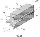
- figure 2d represents the antenna horn of figures 2a And 2b in a three-quarter face view in section along a horizontal plane located in the middle of the horn. It can be observed in particular that the ribs 206 and 206' form protrusions positioned along and in the middle of opposite walls 204 and 204' of the waveguide 201.
- the waveguide 201 is of square section.
- the walls to which the ribs 206 and 206' are attached can either be chosen as the opposite horizontal walls 204 and 204' or the opposite vertical walls 205 and 205'.
- the ribs 206 and 206' of the horizontal walls and the ribs 208 and 208' of the vertical walls can have the same heights and widths.
- the ellipticity rate of the transmitted signals is optimal, and the circular polarization is very pure.
- the waveguide 201 can be chosen as having a non-square rectangular section, in order for example to have accesses 202 and 203 of standard format with an a / b ratio equal to 1 ⁇ 2, or for a mesh of constrained size in order to meet requirements regarding the maximum scanning angle and maximum operating frequency.
- FIG. 3 represents another embodiment of an antenna horn according to the invention, in three-quarter front view. This embodiment differs from that presented in figures 2a to 2d in that the ribs 206, 206', 208 and 208' do not extend outside the waveguide 201.
- a dielectric layer such as layer 115 must be added to the end open of the antenna horn 300 in order to achieve the adaptation between the guided propagation inside the horn and the propagation in free space.
- This embodiment has the drawback of requiring the assembly of a layer of dielectric material with the metal part of the horn.
- the dielectric layer 115 is deposited on the opening of the waveguide 201. It is then simple to assemble and can be adjusted in one piece to all the horns of a network of antenna horns according to the invention, thus limiting manufacturing costs.
- FIG 4 represents a network of antenna horns according to one embodiment of the invention, implementing elementary antenna horns such as that described in figures 2a to 2d .
- the network 400 has a mesh of pitch ⁇ in one dimension and of pitch ⁇ in the other dimension corresponding exactly to the external dimensions of the waveguide 201. Each antenna horn then completely fits the space allocated to it, this which is optimal in terms of occupancy.
- the adjacent ribs of adjacent horns such as the ribs 401 and 402 are connected so as to form only one and the same continuous rib.
- the absence of discontinuities makes it possible, among other things, to reduce the radar equivalent surface (SER) of the array antenna.
- SER radar equivalent surface
- the invention therefore relates to a compact antenna horn which can be integrated into an array of elementary antennas.
- the horn is described in relation to the application case of Ka-band satellite communications, but could be used for any type of communications in a given frequency band involving the transmission of two circularly polarized signals.
- the invention also relates to radiocommunication equipment comprising an antenna horn or a network of antenna horns according to the invention.
- the radiocommunications equipment can for example be embarked on a land or air vehicle.
- the invention relates to a method of telecommunications, in particular by satellite, between two radiocommunications equipment according to the invention.
- the method comprises transmitting and/or receiving signals using an antenna horn or an antenna horn array according to the invention.
Landscapes
- Physics & Mathematics (AREA)
- Engineering & Computer Science (AREA)
- Astronomy & Astrophysics (AREA)
- General Physics & Mathematics (AREA)
- Remote Sensing (AREA)
- Aviation & Aerospace Engineering (AREA)
- Waveguide Aerials (AREA)
Claims (12)
- Antennenhorn (200, 300), insbesondere für Satellitenkommunikation, das Folgendes umfasst:- einen Wellenleiter (201), der sich entlang einer Längsachse (zz') erstreckt, wobei der Wellenleiter ein offenes Ende und ein den Zugang zu in dem Wellenleiter übertragenen Signalen ermöglichendes Ende aufweist, wobei die gegenüberliegenden breitesten Wände (204, 204') des Wellenleiters ein erstes Paar Wände des Wellenleiters bilden und die beiden anderen Wände (205, 205') des Wellenleiters ein zweites Paar Wände des Wellenleiters bilden,wobei das Antennenhorn ferner Folgendes umfasst:- zwei erste Rippen (206, 206'), die sich entlang der Längsachse innerhalb des Wellenleiters, in der Mitte und über die gesamte Länge jeder der Wände des ersten Wandpaars erstrecken,- eine flache Mittelwand (207, 208, 208'), die sich im Wellenleiter entlang der Längsachse erstreckt, wobei die Mittelwand so konfiguriert ist, dass sie an dem Ende, das den Zugang zu den im Wellenleiter übertragenen Signalen ermöglicht, die beiden Wände des zweiten Wandpaars in ihrer Mitte verbindet (207) und so zwei separate Zugänge (202, 203) zu den Signalen bildet, und in Richtung des offenen Endes des Wellenleiters stoppt, um die von den beiden Zugängen übertragenen Signale gemäß orthogonalen zirkularen Polarisationen zu polarisieren, wobei die Mittelwand zwei zweite Rippen (208, 208') bildet, die sich entlang der Längsachse in der Mitte jeder der Wände des zweiten Wandpaares vom offenen Ende des Wellenleiters aus erstrecken.
- Antennenhorn nach Anspruch 1, wobei der Wellenleiter einen quadratischen Querschnitt hat, wobei zwei beliebige gegenüberliegende Wände des Wellenleiters das erste Wandpaar bilden und die beiden anderen gegenüberliegenden Wände des Wellenleiters das zweite Wandpaar bilden.
- Antennenhorn nach einem der vorhergehenden Ansprüche, wobei der Wellenleiter (201), das erste Paar Rippen (206, 206') und das zweite Paar Rippen (208, 208') Abmessungen haben, die für die Ausbreitung von elektromagnetischen Wellen gemäß den Ausbreitungsmoden TE10 und TE01 im Frequenzband der übertragenen Signale ausgelegt sind, und wobei die beiden Zugänge (202, 203) Abmessungen haben, die für die Ausbreitung von elektromagnetischen Wellen gemäß der Ausbreitungsmode TE10 ausgelegt sind.
- Antennenhorn nach einem der vorhergehenden Ansprüche, das ferner eine Schicht aus dielektrischem Material (115) umfasst, die so positioniert ist, dass sie das offene Ende des Wellenleiters bedeckt, und zum Realisieren des Abgleichs zwischen der Ausbreitung innerhalb des Wellenleiters und der Ausbreitung im freien Raum konfiguriert ist.
- Antennenhorn nach einem der Ansprüche 1 bis 3, wobei sich die ersten (206, 206') und zweiten (208, 208') Rippen außerhalb des Wellenleiters durch sein offenes Ende erstrecken, während sie außerhalb des Wellenleiters eine aufgeweitete Form haben.
- Antennenhorn nach einem der vorhergehenden Ansprüche, wobei die beiden ersten Rippen (206, 206') identische Höhen und Breiten haben und wobei die beiden zweiten Rippen (208, 208') identische Höhen und Breiten haben.
- Antennenhorn nach einem der vorhergehenden Ansprüche, wobei einer der durch die Mittelwand (207) und den Wellenleiter (201) gebildeten Zugänge (202) zum Einspeisen eines ersten Signals mit einer ersten Frequenz verwendet wird, und wobei der andere Zugang (203) zum Extrahieren eines Signals mit einer zweiten Frequenz verwendet wird, die sich von der ersten Frequenz unterscheidet, wobei die erste Frequenz und die zweite Frequenz zum Ka-Band des elektromagnetischen Spektrums gehören.
- Antennenhorn nach einem der vorhergehenden Ansprüche, wobei die Seiten des Querschnitts des Wellenleiters kleiner als λ/2 sind, wobei λ die Wellenlänge der auszusendenden Signale ist.
- Antenne, die mindestens ein Antennenhorn nach einem der vorhergehenden Ansprüche umfasst.
- Antenne nach Anspruch 9, das ein Netzwerk (400) von mindestens zwei Antennenhörnern nach einem der vorhergehenden Ansprüche umfasst, die in einem Maschennetz mit regelmäßiger Teilung angeordnet sind, wobei sich die ersten (206, 206') und zweiten (208, 208') Rippen mit ihren offenen Enden außerhalb der Wellenleiter erstrecken, indem sie eine aufgeweitete Form haben, wobei die benachbarten Antennenhörner durch das Ende eines ihrer Rippen außerhalb der Wellenleiter verbunden sind.
- Funkkommunikationsausrüstung, die eine Antenne nach einem der Ansprüche 9 und 10 umfasst.
- Telekommunikationsverfahren, insbesondere über Satellit, zwischen zwei Stationen, wobei das Verfahren die Verwendung einer Funkkommunikationsausrüstung nach Anspruch 11 umfasst.
Applications Claiming Priority (1)
| Application Number | Priority Date | Filing Date | Title |
|---|---|---|---|
| FR1915417A FR3105884B1 (fr) | 2019-12-26 | 2019-12-26 | Cornet pour antenne satellite bi-bande Ka à polarisation circulaire |
Publications (2)
| Publication Number | Publication Date |
|---|---|
| EP3843202A1 EP3843202A1 (de) | 2021-06-30 |
| EP3843202B1 true EP3843202B1 (de) | 2023-09-20 |
Family
ID=70804664
Family Applications (1)
| Application Number | Title | Priority Date | Filing Date |
|---|---|---|---|
| EP20216598.1A Active EP3843202B1 (de) | 2019-12-26 | 2020-12-22 | Horn für eine zirkular polarisierte duale ka-band-satellitenantenne |
Country Status (5)
| Country | Link |
|---|---|
| US (1) | US11437727B2 (de) |
| EP (1) | EP3843202B1 (de) |
| ES (1) | ES2964974T3 (de) |
| FR (1) | FR3105884B1 (de) |
| IL (1) | IL279708B2 (de) |
Families Citing this family (4)
| Publication number | Priority date | Publication date | Assignee | Title |
|---|---|---|---|---|
| CN113889745B (zh) * | 2021-09-30 | 2022-05-03 | 北京星英联微波科技有限责任公司 | 紧凑型宽带圆极化天线 |
| US11881607B1 (en) * | 2021-10-05 | 2024-01-23 | Lockheed Martin Corporation | Longitudinally ridged septum orthomode transducer polarizer |
| CN114744390B (zh) * | 2022-04-26 | 2024-01-26 | 北京华镁钛科技有限公司 | 一种差分波导功分器 |
| WO2024100614A1 (fr) * | 2022-11-11 | 2024-05-16 | Swissto12 Sa | Antenne striée a double polarisation |
Citations (2)
| Publication number | Priority date | Publication date | Assignee | Title |
|---|---|---|---|---|
| KR101117648B1 (ko) * | 2010-09-17 | 2012-03-20 | 홍익대학교 산학협력단 | 4분할 도파관을 이용한 직교모드 변환기 |
| US9640847B2 (en) * | 2015-05-27 | 2017-05-02 | Viasat, Inc. | Partial dielectric loaded septum polarizer |
Family Cites Families (25)
| Publication number | Priority date | Publication date | Assignee | Title |
|---|---|---|---|---|
| US3458862A (en) * | 1966-08-08 | 1969-07-29 | Esl Inc | Quadruply ridged waveguide and horn antenna |
| US3714652A (en) * | 1971-04-19 | 1973-01-30 | Us Navy | Single error channel monopulse system |
| JP3739637B2 (ja) * | 2000-07-27 | 2006-01-25 | アルプス電気株式会社 | 一次放射器 |
| US6323819B1 (en) * | 2000-10-05 | 2001-11-27 | Harris Corporation | Dual band multimode coaxial tracking feed |
| US6489931B2 (en) * | 2000-12-21 | 2002-12-03 | Emc Test Systems, Lp | Diagonal dual-polarized broadband horn antenna |
| US6507323B1 (en) * | 2001-03-28 | 2003-01-14 | Rockwell Collins, Inc. | High-isolation polarization diverse circular waveguide orthomode feed |
| US6650291B1 (en) * | 2002-05-08 | 2003-11-18 | Rockwell Collins, Inc. | Multiband phased array antenna utilizing a unit cell |
| US7642979B2 (en) * | 2004-08-18 | 2010-01-05 | Telefonaktiebolaget L M (Publ) | Wave-guide-notch antenna |
| US7688268B1 (en) * | 2006-07-27 | 2010-03-30 | Rockwell Collins, Inc. | Multi-band antenna system |
| DE102007044895B4 (de) * | 2007-09-20 | 2013-06-20 | Rohde & Schwarz Gmbh & Co. Kg | Hornantenne |
| US8026859B2 (en) * | 2008-08-07 | 2011-09-27 | Tdk Corporation | Horn antenna with integrated impedance matching network for improved operating frequency range |
| US8248321B2 (en) * | 2009-09-01 | 2012-08-21 | Raytheon Company | Broadband/multi-band horn antenna with compact integrated feed |
| US9112279B2 (en) * | 2011-02-25 | 2015-08-18 | Honeywell International Inc. | Aperture mode filter |
| CN104428949B (zh) * | 2012-07-03 | 2017-05-24 | 利萨·德雷克塞迈尔有限责任公司 | 包括电介质填充喇叭天线的用于GHz频率范围的宽带卫星通信的天线系统 |
| FR3013909B1 (fr) | 2013-11-28 | 2016-01-01 | Thales Sa | Cornet, antennaire elementaire, structure antennaire et procede de telecommunication associes |
| US9991607B1 (en) * | 2015-06-04 | 2018-06-05 | Rockwell Collins, Inc. | Circular array of ridged waveguide horns |
| EP3179634B1 (de) * | 2015-12-11 | 2021-04-21 | Nokia Shanghai Bell Co., Ltd. | Strahlungs-/aufnahmeelement für eine kompakte mehrbandantenne |
| US10854984B2 (en) * | 2016-03-10 | 2020-12-01 | The Boeing Company | Air-filled quad-ridge radiator for AESA applications |
| US9972897B1 (en) * | 2017-08-09 | 2018-05-15 | Northrop Grumman Systems Corporation | L-band array element with integrated triplexer for GPS payloads |
| JP7294608B2 (ja) * | 2017-08-18 | 2023-06-20 | ニデックエレシス株式会社 | アンテナアレイ |
| CA3100449C (en) * | 2018-06-01 | 2022-08-30 | Swissto12 Sa | Radiofrequency module |
| WO2020124952A1 (zh) * | 2018-12-20 | 2020-06-25 | 胡南 | 电控切换多极化喇叭天线 |
| FR3094575B1 (fr) * | 2019-03-28 | 2022-04-01 | Swissto12 Sa | Composant radiofréquence comportant un ou plusieurs dispositifs à guide d’onde muni de stries |
| US11688939B2 (en) * | 2019-07-29 | 2023-06-27 | KYOCERA AVX Components (San Diego), Inc. | Horn antennas for use in a radio frequency anechoic test chamber |
| US11031692B1 (en) * | 2020-04-20 | 2021-06-08 | Nan Hu | System including antenna and ultra-wideband ortho-mode transducer with ridge |
-
2019
- 2019-12-26 FR FR1915417A patent/FR3105884B1/fr active Active
-
2020
- 2020-12-22 EP EP20216598.1A patent/EP3843202B1/de active Active
- 2020-12-22 ES ES20216598T patent/ES2964974T3/es active Active
- 2020-12-22 US US17/131,535 patent/US11437727B2/en active Active
- 2020-12-23 IL IL279708A patent/IL279708B2/en unknown
Patent Citations (2)
| Publication number | Priority date | Publication date | Assignee | Title |
|---|---|---|---|---|
| KR101117648B1 (ko) * | 2010-09-17 | 2012-03-20 | 홍익대학교 산학협력단 | 4분할 도파관을 이용한 직교모드 변환기 |
| US9640847B2 (en) * | 2015-05-27 | 2017-05-02 | Viasat, Inc. | Partial dielectric loaded septum polarizer |
Also Published As
| Publication number | Publication date |
|---|---|
| EP3843202A1 (de) | 2021-06-30 |
| FR3105884B1 (fr) | 2021-12-03 |
| US20210203076A1 (en) | 2021-07-01 |
| FR3105884A1 (fr) | 2021-07-02 |
| IL279708B1 (en) | 2023-11-01 |
| ES2964974T3 (es) | 2024-04-10 |
| US11437727B2 (en) | 2022-09-06 |
| IL279708A (en) | 2021-06-30 |
| IL279708B2 (en) | 2024-03-01 |
Similar Documents
| Publication | Publication Date | Title |
|---|---|---|
| EP3843202B1 (de) | Horn für eine zirkular polarisierte duale ka-band-satellitenantenne | |
| EP3547450B1 (de) | Strahlungselement mit kreispolarisierung, bei dem eine resonanz in einem fabry-perot-interferometer angewandt wird | |
| EP2415120B1 (de) | Mehrschichtige pillbox-antenne mit parallelen ebenen und entsprechendes antennensystem | |
| EP2564466B1 (de) | Kompaktes strahlungselement mit hohlraumresonatoren | |
| EP0108463B1 (de) | Strahlelement für orthogonal polarisierte Signale und flache Antennengruppe mit solchen nebeneinandergestellten Elementen | |
| FR2810164A1 (fr) | Perfectionnement aux antennes source d'emission/reception d'ondes electromagnetiques pour systemes de telecommunications par satellite | |
| FR2966986A1 (fr) | Element rayonnant d'antenne | |
| FR2652453A1 (fr) | Antenne coaxiale a fentes du type a alimentation a ondes progressives. | |
| FR2904478A1 (fr) | Dispositif de transduction orthomode a compacite optimisee dans le plan de maille, pour une antenne | |
| FR2942915A1 (fr) | Systeme d'antennes compact | |
| EP3726642B1 (de) | Polarisationsschirm mit breitband-hochfrequenz-polarisationszelle(n) | |
| FR2800920A1 (fr) | Dispositif de transmission bi-bande et antenne pour ce dispositif | |
| FR2863110A1 (fr) | Antenne en reseau multi-bande a double polarisation | |
| EP2059973B1 (de) | Mehreren antennensystem mit polarisationsdiversität | |
| EP3840124B1 (de) | Leckwellenantenne mit afsiw-technologie | |
| WO2003061062A1 (fr) | Dispositif pour la reception et/ou l'emission d'ondes electromagnetiques a diversite de rayonnement | |
| FR2704359A1 (fr) | Antenne plane. | |
| EP1188202B1 (de) | Anordnung zur übertragung und/oder zum empfang von signalen | |
| EP0520908B1 (de) | Lineare Gruppenantenne | |
| FR2917242A1 (fr) | Perfectionnement aux antennes large bande. | |
| FR2871619A1 (fr) | Antenne large bande et a rayonnement omnidirectionnel | |
| EP3306746B1 (de) | Strahlungselement in einem hohlraum, und strahlungsnetz, das mindestens zwei strahlungselemente umfasst | |
| EP0831550B1 (de) | Vielseitige Gruppenantenne | |
| EP2889955B1 (de) | Kompaktantennenstruktur für Telekommunikationen über Satelliten | |
| WO2023031543A1 (fr) | Antenne multi-bandes |
Legal Events
| Date | Code | Title | Description |
|---|---|---|---|
| PUAI | Public reference made under article 153(3) epc to a published international application that has entered the european phase |
Free format text: ORIGINAL CODE: 0009012 |
|
| STAA | Information on the status of an ep patent application or granted ep patent |
Free format text: STATUS: THE APPLICATION HAS BEEN PUBLISHED |
|
| AK | Designated contracting states |
Kind code of ref document: A1 Designated state(s): AL AT BE BG CH CY CZ DE DK EE ES FI FR GB GR HR HU IE IS IT LI LT LU LV MC MK MT NL NO PL PT RO RS SE SI SK SM TR |
|
| STAA | Information on the status of an ep patent application or granted ep patent |
Free format text: STATUS: REQUEST FOR EXAMINATION WAS MADE |
|
| 17P | Request for examination filed |
Effective date: 20211220 |
|
| RBV | Designated contracting states (corrected) |
Designated state(s): AL AT BE BG CH CY CZ DE DK EE ES FI FR GB GR HR HU IE IS IT LI LT LU LV MC MK MT NL NO PL PT RO RS SE SI SK SM TR |
|
| GRAP | Despatch of communication of intention to grant a patent |
Free format text: ORIGINAL CODE: EPIDOSNIGR1 |
|
| STAA | Information on the status of an ep patent application or granted ep patent |
Free format text: STATUS: GRANT OF PATENT IS INTENDED |
|
| P01 | Opt-out of the competence of the unified patent court (upc) registered |
Effective date: 20230517 |
|
| INTG | Intention to grant announced |
Effective date: 20230531 |
|
| GRAS | Grant fee paid |
Free format text: ORIGINAL CODE: EPIDOSNIGR3 |
|
| GRAA | (expected) grant |
Free format text: ORIGINAL CODE: 0009210 |
|
| STAA | Information on the status of an ep patent application or granted ep patent |
Free format text: STATUS: THE PATENT HAS BEEN GRANTED |
|
| AK | Designated contracting states |
Kind code of ref document: B1 Designated state(s): AL AT BE BG CH CY CZ DE DK EE ES FI FR GB GR HR HU IE IS IT LI LT LU LV MC MK MT NL NO PL PT RO RS SE SI SK SM TR |
|
| REG | Reference to a national code |
Ref country code: GB Ref legal event code: FG4D Free format text: NOT ENGLISH |
|
| REG | Reference to a national code |
Ref country code: CH Ref legal event code: EP |
|
| REG | Reference to a national code |
Ref country code: IE Ref legal event code: FG4D Free format text: LANGUAGE OF EP DOCUMENT: FRENCH |
|
| REG | Reference to a national code |
Ref country code: DE Ref legal event code: R096 Ref document number: 602020017927 Country of ref document: DE |
|
| PGFP | Annual fee paid to national office [announced via postgrant information from national office to epo] |
Ref country code: NL Payment date: 20231123 Year of fee payment: 4 |
|
| REG | Reference to a national code |
Ref country code: NL Ref legal event code: FP |
|
| REG | Reference to a national code |
Ref country code: LT Ref legal event code: MG9D |
|
| PG25 | Lapsed in a contracting state [announced via postgrant information from national office to epo] |
Ref country code: GR Free format text: LAPSE BECAUSE OF FAILURE TO SUBMIT A TRANSLATION OF THE DESCRIPTION OR TO PAY THE FEE WITHIN THE PRESCRIBED TIME-LIMIT Effective date: 20231221 |
|
| PG25 | Lapsed in a contracting state [announced via postgrant information from national office to epo] |
Ref country code: SE Free format text: LAPSE BECAUSE OF FAILURE TO SUBMIT A TRANSLATION OF THE DESCRIPTION OR TO PAY THE FEE WITHIN THE PRESCRIBED TIME-LIMIT Effective date: 20230920 Ref country code: RS Free format text: LAPSE BECAUSE OF FAILURE TO SUBMIT A TRANSLATION OF THE DESCRIPTION OR TO PAY THE FEE WITHIN THE PRESCRIBED TIME-LIMIT Effective date: 20230920 Ref country code: NO Free format text: LAPSE BECAUSE OF FAILURE TO SUBMIT A TRANSLATION OF THE DESCRIPTION OR TO PAY THE FEE WITHIN THE PRESCRIBED TIME-LIMIT Effective date: 20231220 Ref country code: LV Free format text: LAPSE BECAUSE OF FAILURE TO SUBMIT A TRANSLATION OF THE DESCRIPTION OR TO PAY THE FEE WITHIN THE PRESCRIBED TIME-LIMIT Effective date: 20230920 Ref country code: LT Free format text: LAPSE BECAUSE OF FAILURE TO SUBMIT A TRANSLATION OF THE DESCRIPTION OR TO PAY THE FEE WITHIN THE PRESCRIBED TIME-LIMIT Effective date: 20230920 Ref country code: HR Free format text: LAPSE BECAUSE OF FAILURE TO SUBMIT A TRANSLATION OF THE DESCRIPTION OR TO PAY THE FEE WITHIN THE PRESCRIBED TIME-LIMIT Effective date: 20230920 Ref country code: GR Free format text: LAPSE BECAUSE OF FAILURE TO SUBMIT A TRANSLATION OF THE DESCRIPTION OR TO PAY THE FEE WITHIN THE PRESCRIBED TIME-LIMIT Effective date: 20231221 Ref country code: FI Free format text: LAPSE BECAUSE OF FAILURE TO SUBMIT A TRANSLATION OF THE DESCRIPTION OR TO PAY THE FEE WITHIN THE PRESCRIBED TIME-LIMIT Effective date: 20230920 |
|
| PGFP | Annual fee paid to national office [announced via postgrant information from national office to epo] |
Ref country code: FR Payment date: 20231122 Year of fee payment: 4 Ref country code: DE Payment date: 20231121 Year of fee payment: 4 |
|
| REG | Reference to a national code |
Ref country code: AT Ref legal event code: MK05 Ref document number: 1614144 Country of ref document: AT Kind code of ref document: T Effective date: 20230920 |
|
| PG25 | Lapsed in a contracting state [announced via postgrant information from national office to epo] |
Ref country code: IS Free format text: LAPSE BECAUSE OF FAILURE TO SUBMIT A TRANSLATION OF THE DESCRIPTION OR TO PAY THE FEE WITHIN THE PRESCRIBED TIME-LIMIT Effective date: 20240120 |
|
| REG | Reference to a national code |
Ref country code: ES Ref legal event code: FG2A Ref document number: 2964974 Country of ref document: ES Kind code of ref document: T3 Effective date: 20240410 |
|
| PGFP | Annual fee paid to national office [announced via postgrant information from national office to epo] |
Ref country code: ES Payment date: 20240115 Year of fee payment: 4 |
|
| PG25 | Lapsed in a contracting state [announced via postgrant information from national office to epo] |
Ref country code: AT Free format text: LAPSE BECAUSE OF FAILURE TO SUBMIT A TRANSLATION OF THE DESCRIPTION OR TO PAY THE FEE WITHIN THE PRESCRIBED TIME-LIMIT Effective date: 20230920 |
|
| PG25 | Lapsed in a contracting state [announced via postgrant information from national office to epo] |
Ref country code: SM Free format text: LAPSE BECAUSE OF FAILURE TO SUBMIT A TRANSLATION OF THE DESCRIPTION OR TO PAY THE FEE WITHIN THE PRESCRIBED TIME-LIMIT Effective date: 20230920 Ref country code: RO Free format text: LAPSE BECAUSE OF FAILURE TO SUBMIT A TRANSLATION OF THE DESCRIPTION OR TO PAY THE FEE WITHIN THE PRESCRIBED TIME-LIMIT Effective date: 20230920 Ref country code: IS Free format text: LAPSE BECAUSE OF FAILURE TO SUBMIT A TRANSLATION OF THE DESCRIPTION OR TO PAY THE FEE WITHIN THE PRESCRIBED TIME-LIMIT Effective date: 20240120 Ref country code: EE Free format text: LAPSE BECAUSE OF FAILURE TO SUBMIT A TRANSLATION OF THE DESCRIPTION OR TO PAY THE FEE WITHIN THE PRESCRIBED TIME-LIMIT Effective date: 20230920 Ref country code: CZ Free format text: LAPSE BECAUSE OF FAILURE TO SUBMIT A TRANSLATION OF THE DESCRIPTION OR TO PAY THE FEE WITHIN THE PRESCRIBED TIME-LIMIT Effective date: 20230920 Ref country code: AT Free format text: LAPSE BECAUSE OF FAILURE TO SUBMIT A TRANSLATION OF THE DESCRIPTION OR TO PAY THE FEE WITHIN THE PRESCRIBED TIME-LIMIT Effective date: 20230920 Ref country code: PT Free format text: LAPSE BECAUSE OF FAILURE TO SUBMIT A TRANSLATION OF THE DESCRIPTION OR TO PAY THE FEE WITHIN THE PRESCRIBED TIME-LIMIT Effective date: 20240122 Ref country code: SK Free format text: LAPSE BECAUSE OF FAILURE TO SUBMIT A TRANSLATION OF THE DESCRIPTION OR TO PAY THE FEE WITHIN THE PRESCRIBED TIME-LIMIT Effective date: 20230920 |