EP3842260B1 - Motorradreifen - Google Patents
Motorradreifen Download PDFInfo
- Publication number
- EP3842260B1 EP3842260B1 EP20209963.6A EP20209963A EP3842260B1 EP 3842260 B1 EP3842260 B1 EP 3842260B1 EP 20209963 A EP20209963 A EP 20209963A EP 3842260 B1 EP3842260 B1 EP 3842260B1
- Authority
- EP
- European Patent Office
- Prior art keywords
- tyre
- steel cords
- ply
- braking
- steel
- Prior art date
- Legal status (The legal status is an assumption and is not a legal conclusion. Google has not performed a legal analysis and makes no representation as to the accuracy of the status listed.)
- Active
Links
Images

Classifications
-
- B—PERFORMING OPERATIONS; TRANSPORTING
- B60—VEHICLES IN GENERAL
- B60C—VEHICLE TYRES; TYRE INFLATION; TYRE CHANGING; CONNECTING VALVES TO INFLATABLE ELASTIC BODIES IN GENERAL; DEVICES OR ARRANGEMENTS RELATED TO TYRES
- B60C9/00—Reinforcements or ply arrangement of pneumatic tyres
- B60C9/18—Structure or arrangement of belts or breakers, crown-reinforcing or cushioning layers
- B60C9/20—Structure or arrangement of belts or breakers, crown-reinforcing or cushioning layers built-up from rubberised plies each having all cords arranged substantially parallel
- B60C9/2003—Structure or arrangement of belts or breakers, crown-reinforcing or cushioning layers built-up from rubberised plies each having all cords arranged substantially parallel characterised by the materials of the belt cords
- B60C9/2006—Structure or arrangement of belts or breakers, crown-reinforcing or cushioning layers built-up from rubberised plies each having all cords arranged substantially parallel characterised by the materials of the belt cords consisting of steel cord plies only
-
- B—PERFORMING OPERATIONS; TRANSPORTING
- B60—VEHICLES IN GENERAL
- B60C—VEHICLE TYRES; TYRE INFLATION; TYRE CHANGING; CONNECTING VALVES TO INFLATABLE ELASTIC BODIES IN GENERAL; DEVICES OR ARRANGEMENTS RELATED TO TYRES
- B60C9/00—Reinforcements or ply arrangement of pneumatic tyres
- B60C9/0007—Reinforcements made of metallic elements, e.g. cords, yarns, filaments or fibres made from metal
-
- B—PERFORMING OPERATIONS; TRANSPORTING
- B60—VEHICLES IN GENERAL
- B60C—VEHICLE TYRES; TYRE INFLATION; TYRE CHANGING; CONNECTING VALVES TO INFLATABLE ELASTIC BODIES IN GENERAL; DEVICES OR ARRANGEMENTS RELATED TO TYRES
- B60C9/00—Reinforcements or ply arrangement of pneumatic tyres
- B60C9/02—Carcasses
-
- B—PERFORMING OPERATIONS; TRANSPORTING
- B60—VEHICLES IN GENERAL
- B60C—VEHICLE TYRES; TYRE INFLATION; TYRE CHANGING; CONNECTING VALVES TO INFLATABLE ELASTIC BODIES IN GENERAL; DEVICES OR ARRANGEMENTS RELATED TO TYRES
- B60C9/00—Reinforcements or ply arrangement of pneumatic tyres
- B60C9/18—Structure or arrangement of belts or breakers, crown-reinforcing or cushioning layers
-
- B—PERFORMING OPERATIONS; TRANSPORTING
- B60—VEHICLES IN GENERAL
- B60C—VEHICLE TYRES; TYRE INFLATION; TYRE CHANGING; CONNECTING VALVES TO INFLATABLE ELASTIC BODIES IN GENERAL; DEVICES OR ARRANGEMENTS RELATED TO TYRES
- B60C9/00—Reinforcements or ply arrangement of pneumatic tyres
- B60C2009/0071—Reinforcements or ply arrangement of pneumatic tyres characterised by special physical properties of the reinforcements
- B60C2009/0092—Twist structure
-
- B—PERFORMING OPERATIONS; TRANSPORTING
- B60—VEHICLES IN GENERAL
- B60C—VEHICLE TYRES; TYRE INFLATION; TYRE CHANGING; CONNECTING VALVES TO INFLATABLE ELASTIC BODIES IN GENERAL; DEVICES OR ARRANGEMENTS RELATED TO TYRES
- B60C9/00—Reinforcements or ply arrangement of pneumatic tyres
- B60C9/18—Structure or arrangement of belts or breakers, crown-reinforcing or cushioning layers
- B60C2009/1828—Structure or arrangement of belts or breakers, crown-reinforcing or cushioning layers characterised by special physical properties of the belt ply
-
- B—PERFORMING OPERATIONS; TRANSPORTING
- B60—VEHICLES IN GENERAL
- B60C—VEHICLE TYRES; TYRE INFLATION; TYRE CHANGING; CONNECTING VALVES TO INFLATABLE ELASTIC BODIES IN GENERAL; DEVICES OR ARRANGEMENTS RELATED TO TYRES
- B60C9/00—Reinforcements or ply arrangement of pneumatic tyres
- B60C9/18—Structure or arrangement of belts or breakers, crown-reinforcing or cushioning layers
- B60C9/20—Structure or arrangement of belts or breakers, crown-reinforcing or cushioning layers built-up from rubberised plies each having all cords arranged substantially parallel
- B60C9/22—Structure or arrangement of belts or breakers, crown-reinforcing or cushioning layers built-up from rubberised plies each having all cords arranged substantially parallel the plies being arranged with all cords disposed along the circumference of the tyre
- B60C2009/2252—Physical properties or dimension of the zero degree ply cords
- B60C2009/2276—Tensile strength
-
- B—PERFORMING OPERATIONS; TRANSPORTING
- B60—VEHICLES IN GENERAL
- B60C—VEHICLE TYRES; TYRE INFLATION; TYRE CHANGING; CONNECTING VALVES TO INFLATABLE ELASTIC BODIES IN GENERAL; DEVICES OR ARRANGEMENTS RELATED TO TYRES
- B60C9/00—Reinforcements or ply arrangement of pneumatic tyres
- B60C9/18—Structure or arrangement of belts or breakers, crown-reinforcing or cushioning layers
- B60C9/20—Structure or arrangement of belts or breakers, crown-reinforcing or cushioning layers built-up from rubberised plies each having all cords arranged substantially parallel
- B60C9/22—Structure or arrangement of belts or breakers, crown-reinforcing or cushioning layers built-up from rubberised plies each having all cords arranged substantially parallel the plies being arranged with all cords disposed along the circumference of the tyre
- B60C2009/2252—Physical properties or dimension of the zero degree ply cords
- B60C2009/2285—Twist structures
-
- B—PERFORMING OPERATIONS; TRANSPORTING
- B60—VEHICLES IN GENERAL
- B60C—VEHICLE TYRES; TYRE INFLATION; TYRE CHANGING; CONNECTING VALVES TO INFLATABLE ELASTIC BODIES IN GENERAL; DEVICES OR ARRANGEMENTS RELATED TO TYRES
- B60C2200/00—Tyres specially adapted for particular applications
- B60C2200/10—Tyres specially adapted for particular applications for motorcycles, scooters or the like
Definitions
- the present invention relates to a motorcycle tyre according to the preamble of claim 1.
- JP 2018 - 167 716 A (also referred to as "Patent document 1”) discloses a motorcycle tyre including a carcass and a band layer disposed radially outwardly of the carcass.
- the band layer includes a band ply including one or more steel band cords wound spirally in the tyre circumferential direction.
- compressive stiffness and bending stiffness of the band cords are limited to a certain range to improve handling stability.
- braking force should increase gradually in proportion to the deceleration (the acceleration opposite to the direction of travel) of a motorcycle from the start of braking to the end.
- deceleration the acceleration opposite to the direction of travel
- braking stability improving stability during braking
- the inventors have studied rapid changes in braking force as described above. As a result, it has been found that when compressive rigidity of the band cords is relatively high, some of the band cords located in the tread contact region bend suddenly in the tyre radial direction of the tread contact region in the middle of braking in a waving manner. Then, it is assumed that waving of the band cords in the middle of braking causes rapid increase or decrease an area of the tread contact region, leading to rapid changes in braking force.
- the present invention has been made in view of the above circumstances and it is an object of the invention to further develop a motorcycle tyre according to the preamble of claim 1 such that it is capable of improving braking stability.
- FIG 1 is a cross-sectional view of a motorcycle tyre (hereinafter, simply referred to as "tyre") 1 according to the present embodiment of the present invention (hereinafter, simply referred to as “the present embodiment”).
- the tyre 1 according to the present embodiment may suitably be used for a road race. Note that the present invention is defined by the subject-matter of the appended claims.
- the tyre 1 includes a tread portion 2, and a pair of bead portions 4 each with a bead core 5 therein.
- the tread portion 2 has a tread surface 2S extending between tread edges Te through the tyre equator C so as to protrude radially outwardly in an arc shape manner.
- the tread width TW which is a distance in the tyre axial direction between the tread edges Te corresponds to the tyre maximum width.
- the tyre 1 is capable of cornering with large bank angles.
- the tyre 1 includes a toroidal carcass 6 extending between the pair of bead portions 4, and a band layer 7 disposed outward in a tyre radial direction of the carcass and inside the tread portion 2.
- the carcass 6 includes at least one carcass ply.
- the carcass 6 includes two carcass plies that includes an inner carcass ply 6A, and an outer carcass ply 6B disposed radially outwardly of the inner carcass ply 6A at the location of the tyre equator C.
- Each of the inner carcass ply 6A and the outer carcass ply 6B includes a main portion 6a extending between the bead cores 5 of the bead portions 4 through the tread portion 2 and sidewall portions 3, and a pair of turn-up portion 6b each turned up around a respective one of the bead cores 5.
- a bead apex rubber 8 that extends radially outwardly from a respective one of the bead cores 5 is disposed between the main portion 6a and a respective one of the turn-up portions 6b.
- the inner carcass ply 6A and the outer carcass ply 6B include carcass cords (not illustrated).
- the carcass cords are oriented at an angle of 60 to 90 degrees with respect to the tyre circumferential direction, for example.
- an organic fiber cord such as nylon, polyester, rayon and the like may preferably be employed, for example.
- the band layer 7 includes at least one band ply 7A, and in the present embodiment, one band ply 7A is employed.
- the band ply 7A has one or more steel cords 12 spirally wound in the tyre circumferential direction.
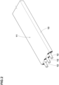
- FIG 2 is a partial perspective view of one example of a ribbon ply 11.
- the band ply 7A according to the present embodiment is formed by arranging the ribbon ply 11 shown in FIG 2 (e.g., by winding the ribbon ply 11 spirally) in the tyre circumferential direction.
- the ribbon ply 11 is configured to include one or more steel cords 12 (a plurality of steel cords 12 in the present example) and a topping rubber 13 coating the steel cords 12.
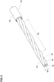
- FIG 3 is a partial perspective view of one of the steel cords according to the present embodiment.
- each steel cord 12 includes a plurality of twisted filaments 14.
- FIG 3 illustrates a single-twisted cord with a 1x4 structure in which four filaments 14 are twisted together.
- the steel cords 12 are not limited to the above.
- a single-twisted cord with a 1x5 structure, and a double twisted cord with a 3x3 structure may be adopted.
- the filaments 14 one or more pre-molded filaments (not illustrated) that are given a predetermined shape at a state before twisting, as in Patent Document 1, may be employed.
- the plurality of twisted filaments 14 is coated with rubber 15.
- the rubber 15 is filled between the filaments 14.
- the rubber 15 according to the present embodiment has the same composition as the topping rubber 13 of the band ply 7A shown in FIG 2 .
- the tubber 15 is not limited to the above. The rubber 15 can prevent the filaments 14 of the steel cord 12 from contacting directly with one another so that damages due to contacting of the filaments 14 with one another is prevented.
- the tyre 1 has a parameter (A) in which a load index LI (kg) of the tyre 1 is divided by a bending/compression stiffness ratio that is obtained by dividing a bending stiffness (g ⁇ cm) of the steel cords by a compression stiffness (N/mm) of the steel cords 12 being in a range of 1500 to 6000.
- the load index LI is an index which indicates the maximum mass (maximum load capacity) that can be supported by a single tyre 1 (shown in FIG 1 ).
- the maximum load capacity (kg) corresponding to the Load Index LI of the tyre 1 is specified based on the "Table of correspondence between air pressure and load capacity" defined by the standard organization on which the tyre 1 is based.
- the bending stiffness (g/cm) is a bending stiffness of a single steel cord 12.
- the compressive stiffness (N/mm) is a compressive stiffness of a single steel cord 12.
- the bending stiffness and the compressive stiffness of the steel cord 12 are measured according to the procedure for measuring the compressive stiffness and the bending stiffness of the band cord as described in the above-mentioned Patent document 1.
- the compressive stiffness and the bending stiffness of the steel cord 12 can be adjusted as described in Patent Document 1.
- the compressive stiffness and the bending stiffness of the steel cord 12 may be adjusted by changing a twisting pitch P1 of the steel cord 12, the number of filaments 14, the outer diameter D1 of the filaments 14, and the number of pre-molded filaments (not illustrated).
- the bending/compression stiffness ratio specifies the relationship between the bending stiffness (g ⁇ cm) and the compressive stiffness (N/mm) of the steel cords 12.
- the parameter (A) which indicates the relationship between the bending/compression stiffness ratio and the load index (kg), is limited to 1500 to 6000, so that the binding/compression stiffness ratio is set in a certain range in relation to the load index (maximum load capacity).
- the bending/compression stiffness ratio with respect to the load index is greater than that of the conventional steel cords.
- such steel cords 12 receive compressive force (magnitude thereof is related to the magnitude of the load index (maximum load capacity)) at the tread contact region, they may buckle easily at or immediately the start of braking.
- the steel cords 12 located in the tread contact region can deform in a wavy manner. Such a wave-like deformation can make an area of the tread contact region linearly change and can stabilize braking force compared to that without the wave-like deformation.
- the tyre 1 according to the present embodiment (shown in FIG 1 ) can generate wave-like deformation of the steel cord 12 located in the tread contact region from or immediately after the start of braking.
- the tyre 1 can suppress a rapid change in area of the tread contact region from the start of braking to the end.
- the tyre 1 according to the present embodiment can gradually increase braking force from the start to the end of braking of a motorcycle so as to be proportional to deceleration of the vehicle (acceleration opposite to the traveling direction). Therefore, the tyre 1 according to the present embodiment can provide a stable braking force during braking.
- the tyre 1 according to the present embodiment (shown in FIG 1 ) is capable of causing a wave-like deformation to the steel cords 12, which are located in the tread contact region, when a motorcycle starts to turn or immediately afterwards.
- the tyre 1 according to the present embodiment can gradually increase cornering force in proportion to the load on the tyre 1 during cornering, and thus handling stability can be improved.
- the bending/compression stiffness ratio of the steel cord 12 can be increased relatively by setting the parameter (A) to less than 6000.
- the tyre 1 shown in FIG 1 ) according to the present embodiment can deform the steel cords 12, which are located in the tread contact region, in a wave-like manner from the start of braking or immediately afterwards.
- the tyre 1 according to the present embodiment can prevent a rapid change in area of the tread contact region in the middle of braking.
- the bending stiffness of the steel cords 12 can be prevented from being higher than necessary by setting the parameter (A) to more than 1500.
- the compression input to the steel cords 12 can be converted to bent the steel cords 12 when the vehicle is braking.
- the tyre 1 according to the present embodiment can deform the steel cords 12 to a wavy-like manner at or immediately after the start of braking. This can prevent a rapid change in area of the tread contact region in the middle of braking.
- the steel cords 12 are prevented from increasing its bending stiffness.
- the steel cords 12 can be positioned along the outer surface of the outer carcass ply 6B (shown in FIG 1 ), which is curved in a convex arc. This can improve the formability of the band ply 7A, and thus it can prevent the steel cords 12 (in particular, the winding end of the steel cords 12) from being lifted out in the tyre radial direction.
- the parameter (A) is preferably equal to or less than 5000, more preferably equal to or less than 4500, but preferably equal to or more than 2500, more preferably equal to or more than 3000.
- the bending stiffness of the steel cords 12 is in a range of 16 to 50 (g ⁇ cm).
- the bending stiffness equal to or less than 50 (g ⁇ cm)
- compression input to the steel cords 12 acting when a motorcycle is braking is converted into bending deformation of the steel cords 12.
- the tyre 1 according to the present embodiment (shown in FIG 1 ) can deform the steel cords 12 to a wavy-like manner at or immediately after the start of braking.
- the steel cords 12 are flexible and bent easily, which increases resistance to bending fatigue (durability of the steel cords 12).
- the bending stiffness is set to 16 (g-cm) or more, which can prevent wavy-deformation of the steel cords 12 from becoming larger than necessary.
- the tyre 1 according to the present embodiment shown in FIG 1 ) can maintain rigidity of the tread contact surface, and thus braking and handling stability may be improved.
- the bending stiffness is preferably equal to or less than 40 (g ⁇ cm), and preferably equal to or more than 25 (g ⁇ cm).
- the compression stiffness of the steel cords 12 is in a range of 150 to 350 (N/mm).
- the compression stiffness is set equal to or less than 350 (N/mm)
- a wavy-like deformation of the steel cords 12 in the tread ground region of the tyre 1 can occur at the start of braking or immediately afterwards.
- the compression input to the steel cords 12 can be converted into its wavy bending deformation.
- the tyre 1 according to the present embodiment can increase compression fatigue resistance (durability) of the steel cords 12.
- the compression stiffness is preferably equal to or less than 300 (N/mm), and preferably equal to or more than 200 (N/mm).
- the rubber 15 is filled between the filaments 14.
- Such rubber 15 is capable of absorbing part of the force acting on the filaments 14 of the steel cords 12, which are located in the tread contact region when a motorcycle is braking.
- the tyre 1 according to the present embodiment shown in FIG 1 ) can prevent the steel cords 12 from waving more than necessary, and thus improving braking and handling stability.
- a parameter (B) of each steel cord 12 in which the number of filaments 14 of each steel cord 12 is divided by a twisting pitch (mm) of a respective one of the steel cords 12 is less than 1.5 (threads/mm).
- the steel cords 12 can prevent the steel cords 12 from increasing in outer diameter as well as from decreasing in compression stiffness more than necessary, even when the steel cords 12 are subjected to compression force during braking. Therefore, the tyre 1 of the present embodiment (shown in FIG 1 ) can maintain stiffness of the tread contact region, improving braking and handling stability.
- the parameter (B) is preferably less than 1.0 (threads/mm).
- the parameter (B) is set equal to or more than 0.3 (threads/mm). This can prevent the compression stiffness of the steel cords 12 from being greater than necessary.
- the tyre 1 shown in FIG 1 ) according to the present embodiment can cause wavy-deformation of the steel cord 12 at the start of braking or immediately afterwards.
- the number of the steel cords 12 in the ribbon ply 11 shown in FIG 2 is equal to or less than 5. This can prevent the tyre 1 according to the present embodiment (shown in FIG 1 ) from having a large difference in the winding diameter of each steel cord 12 in the ribbon ply 11 due to the curvature of the outer carcass ply 6B. Thus, the tyre 1 can have a nearly uniform distribution of stiffness in the tyre axial direction of the band ply 7A, improving braking and handling stability.
- the number of the steel cords 12 in the ribbon ply 11 is preferably 4 or less, and more preferably 3 or less.
- the number of the steel cords 12 in the ribbon ply 11 is equal to or more than two. This can prevent the increase in the number of winding of the ribbon ply 11 in the manufacturing process of the tyre 1 (shown in FIG 1 ) and thus prevents the increase in the manufacturing cost.
- Tyres having the basic structure of FIG 1 have been prototyped based on specifications in Tables 1 to 3 (Examples 1 to 23, and references 1 to 5). These tyres were evaluated for braking stability and formability of the band ply.
- the common specification of each tyre is as follows.
- the test method is as follows.
- each test tyre is mounted on the front wheel of the above motorcycle. Then, a test rider rode the test vehicle on a dry asphalt test course to evaluate the braking stability by the rider's sensory using a 10-point method.
- the test results are shown in Tables 1 to 3. The higher value indicates the better the braking stability, meaning that braking force increases in proportion to the deceleration of the motorcycle during the braking.
- the ribbon ply shown in FIG 2 was wound around the tyre circumferential direction to form the band ply of each test tyre. After the winding of the ribbon ply was completed, the ends of steel cords were visually checked whether or not it floated outwardly in the tyre radial direction. The test results are shown in Tables 1 to 3 by "OK" when the steel cords did not float and "NG" when it floated.
- the example tyres have improved braking stability compared to the comparative example tyres, while maintaining the formability of band ply.
- a motorcycle tyre includes a tread portion, a pair of bead portions, a toroidal carcass extending between the pair of bead portions, and a band layer disposed outward in a tyre radial direction of the carcass and inside the tread portion.
- the band layer includes a band ply having one or more steel cords spirally wound in a tyre circumferential direction.
- the tyre has a parameter (A) in which a load index LI (kg) of the tyre is divided by a bending/compression stiffness ratio that is obtained by dividing a bending stiffness (g ⁇ cm) of the steel cords by a compression stiffness (N/mm) of the steel cords being in a range of 1500 to 6000.
Landscapes
- Engineering & Computer Science (AREA)
- Mechanical Engineering (AREA)
- Tires In General (AREA)
Claims (7)
- Motorradreifen (1) mit:einem Laufflächenabschnitt (2);einem Paar Wulstabschnitte (4);einer torusförmigen Karkasse (6), die sich zwischen dem Paar Wulstabschnitte (4) erstreckt; undeiner Bandschicht (7), die außen in einer Reifenradialrichtung der Karkasse (6) und innerhalb des Laufflächenabschnitts (2) angeordnet ist, wobei die Bandschicht (7) eine Bandlage (7A) mit einem oder mehreren Stahlgurten (12) aufweist, der/die wendelförmig in einer Reifenumfangsrichtung gewickelt ist/sind,dadurch gekennzeichnet, dassder Reifen (1) einen Parameter (A) hat, bei dem ein Lastindex LI (kg) des Reifens (1) durch ein Biege-/Kompressionssteifigkeitsverhältnis dividiert wird, das durch Dividieren einer Biegesteifigkeit (g·cm) der Stahlgurte (12) durch eine Kompressionssteifigkeit (N/mm) der Stahlgurte (12) erhalten wird, der in einem Bereich von 1500 bis 6000 ist.
- Motorradreifen (1) nach Anspruch 1, wobei
die Biegesteifigkeit der Stahlgurte (12) in einem Bereich von 16 bis 50 (g·cm) ist. - Motorradreifen (1) nach Anspruch 1 oder 2, wobei
die Stahlgurte (12) eine Vielzahl von verdrillten Filamenten (14) und einen Gummi (15) aufweisen, der zwischen der Vielzahl von Filamenten (14) verfüllt ist. - Motorradreifen (1) nach Anspruch 3, wobei
ein Parameter B der Stahlgurte (12), bei dem eine Anzahl von Filamenten (14) jedes Stahlgurts (12) durch eine Verdrillungssteigung (mm) eines jeweiligen der Stahlgurte (12) dividiert wird, weniger als 1,5 (Stränge/mm) ist. - Motorradreifen (1) nach einem der Ansprüche 1 bis 4, wobeidie Bandlage (7A) ausgebildet ist, indem eine Flachbandlage (11) wendelförmig in der Reifenumfangsrichtung gewickelt wird, unddie Bandlage (11) fünf oder weniger der Stahlgurte (12) und einen Deckgummi (13) aufweist, der die Stahlgurte beschichtet.
- Motorradreifen (1) nach einem der Ansprüche 1 bis 5, wobei
der Parameter (A) in einem Bereich von 2500 bis 5000 ist. - Motorradreifen (1) nach einem der Ansprüche 1 bis 6, wobei
der Parameter (A) in einem Bereich von 3000 bis 4500 ist.
Applications Claiming Priority (1)
| Application Number | Priority Date | Filing Date | Title |
|---|---|---|---|
| JP2019236948A JP7375534B2 (ja) | 2019-12-26 | 2019-12-26 | 自動二輪車用タイヤ |
Publications (2)
| Publication Number | Publication Date |
|---|---|
| EP3842260A1 EP3842260A1 (de) | 2021-06-30 |
| EP3842260B1 true EP3842260B1 (de) | 2023-08-09 |
Family
ID=73598707
Family Applications (1)
| Application Number | Title | Priority Date | Filing Date |
|---|---|---|---|
| EP20209963.6A Active EP3842260B1 (de) | 2019-12-26 | 2020-11-26 | Motorradreifen |
Country Status (4)
| Country | Link |
|---|---|
| US (1) | US11535059B2 (de) |
| EP (1) | EP3842260B1 (de) |
| JP (1) | JP7375534B2 (de) |
| CN (1) | CN113043792B (de) |
Families Citing this family (4)
| Publication number | Priority date | Publication date | Assignee | Title |
|---|---|---|---|---|
| JP7329381B2 (ja) * | 2019-07-22 | 2023-08-18 | 株式会社ブリヂストン | 制御方法、制御装置、制御システムおよびタイヤ試験方法 |
| CN115266342A (zh) * | 2022-07-19 | 2022-11-01 | 泰凯英(青岛)专用轮胎技术研究开发有限公司 | 轮胎钢帘线压缩状态力学性能测试方法 |
| JP2024089176A (ja) * | 2022-12-21 | 2024-07-03 | 株式会社ブリヂストン | 自動二輪車用タイヤ |
| JP2024089175A (ja) * | 2022-12-21 | 2024-07-03 | 株式会社ブリヂストン | 自動二輪車用タイヤ |
Family Cites Families (10)
| Publication number | Priority date | Publication date | Assignee | Title |
|---|---|---|---|---|
| JP4478381B2 (ja) * | 2002-11-08 | 2010-06-09 | 不二精工株式会社 | ボディプライコードが交差したラジアルタイヤ |
| JP3947137B2 (ja) * | 2003-06-12 | 2007-07-18 | 住友ゴム工業株式会社 | 自動二輪車用ラジアルタイヤ |
| US20100218872A1 (en) * | 2006-01-20 | 2010-09-02 | Bridgestone Corporation | Rubber-steel cord composite and tire using the same |
| JP5069517B2 (ja) * | 2007-08-10 | 2012-11-07 | 住友ゴム工業株式会社 | 帯状プライ及びそれを用いた空気入りタイヤ |
| JP5432980B2 (ja) * | 2011-12-22 | 2014-03-05 | 住友ゴム工業株式会社 | 空気入りタイヤ |
| BR112014015893B1 (pt) * | 2011-12-27 | 2020-11-10 | Pirelli Tyre S.P.A. | pneu para motocicletas |
| JP5572148B2 (ja) * | 2011-12-28 | 2014-08-13 | 住友ゴム工業株式会社 | 空気入りタイヤ |
| JP6058294B2 (ja) * | 2012-06-18 | 2017-01-11 | 住友ゴム工業株式会社 | 二輪自動車用空気入りタイヤ |
| JP2014172547A (ja) * | 2013-03-11 | 2014-09-22 | Sumitomo Rubber Ind Ltd | 自動二輪車用ラジアルタイヤ |
| JP6863000B2 (ja) * | 2017-03-30 | 2021-04-21 | 住友ゴム工業株式会社 | 自動二輪車用タイヤ |
-
2019
- 2019-12-26 JP JP2019236948A patent/JP7375534B2/ja active Active
-
2020
- 2020-11-19 CN CN202011300328.7A patent/CN113043792B/zh active Active
- 2020-11-26 EP EP20209963.6A patent/EP3842260B1/de active Active
- 2020-12-04 US US17/112,312 patent/US11535059B2/en active Active
Also Published As
| Publication number | Publication date |
|---|---|
| US20210197619A1 (en) | 2021-07-01 |
| US11535059B2 (en) | 2022-12-27 |
| JP2021104743A (ja) | 2021-07-26 |
| CN113043792B (zh) | 2023-10-31 |
| JP7375534B2 (ja) | 2023-11-08 |
| CN113043792A (zh) | 2021-06-29 |
| EP3842260A1 (de) | 2021-06-30 |
Similar Documents
| Publication | Publication Date | Title |
|---|---|---|
| EP3842260B1 (de) | Motorradreifen | |
| US10589577B2 (en) | Heavy-duty pneumatic tire | |
| JP4814979B2 (ja) | タイヤ用コード及びそれを用いた空気入りタイヤ | |
| EP3530485B2 (de) | Luftreifen | |
| EP2815895A1 (de) | Luftreifen für ein zweirädriges kraftfahrzeug | |
| EP3178666B1 (de) | Reifen für ein zweirädriges fahrzeug | |
| JP4166308B2 (ja) | 空気入りタイヤ | |
| EP1612058B1 (de) | Motorradreifen | |
| JP2001354013A (ja) | 空気入りタイヤ | |
| US11104185B2 (en) | Method of manufacturing motorcycle tire for uneven terrain travel | |
| US20230241922A1 (en) | Pneumatic tire | |
| US20130168003A1 (en) | Pneumatic tire | |
| EP2777948B1 (de) | Radialer Reifen für Motorrad | |
| JP6852092B2 (ja) | 自動二輪車用空気入りタイヤ | |
| WO2016120941A1 (ja) | 自動二輪車用空気入りタイヤ | |
| JPH0516614A (ja) | 空気入りラジアルタイヤ | |
| JP3372347B2 (ja) | 空気入りラジアルタイヤ | |
| JPH01141103A (ja) | 空気入りラジアルタイヤ | |
| WO2021095884A1 (ja) | ランフラットタイヤ | |
| EP4282668B1 (de) | Luftreifen | |
| JPH05604A (ja) | 自動二輪車用ラジアルタイヤ | |
| JP5030545B2 (ja) | 空気入りラジアルタイヤ | |
| JP7572605B2 (ja) | 空気入りタイヤ | |
| JP7188038B2 (ja) | 空気入りタイヤ | |
| EP4282667A1 (de) | Luftreifen |
Legal Events
| Date | Code | Title | Description |
|---|---|---|---|
| PUAI | Public reference made under article 153(3) epc to a published international application that has entered the european phase |
Free format text: ORIGINAL CODE: 0009012 |
|
| STAA | Information on the status of an ep patent application or granted ep patent |
Free format text: STATUS: THE APPLICATION HAS BEEN PUBLISHED |
|
| AK | Designated contracting states |
Kind code of ref document: A1 Designated state(s): AL AT BE BG CH CY CZ DE DK EE ES FI FR GB GR HR HU IE IS IT LI LT LU LV MC MK MT NL NO PL PT RO RS SE SI SK SM TR |
|
| STAA | Information on the status of an ep patent application or granted ep patent |
Free format text: STATUS: REQUEST FOR EXAMINATION WAS MADE |
|
| 17P | Request for examination filed |
Effective date: 20210712 |
|
| STAA | Information on the status of an ep patent application or granted ep patent |
Free format text: STATUS: EXAMINATION IS IN PROGRESS |
|
| 17Q | First examination report despatched |
Effective date: 20220720 |
|
| GRAP | Despatch of communication of intention to grant a patent |
Free format text: ORIGINAL CODE: EPIDOSNIGR1 |
|
| STAA | Information on the status of an ep patent application or granted ep patent |
Free format text: STATUS: GRANT OF PATENT IS INTENDED |
|
| RIC1 | Information provided on ipc code assigned before grant |
Ipc: B60C 9/18 20060101ALN20230417BHEP Ipc: B60C 9/00 20060101AFI20230417BHEP |
|
| INTG | Intention to grant announced |
Effective date: 20230516 |
|
| P01 | Opt-out of the competence of the unified patent court (upc) registered |
Effective date: 20230510 |
|
| GRAS | Grant fee paid |
Free format text: ORIGINAL CODE: EPIDOSNIGR3 |
|
| GRAA | (expected) grant |
Free format text: ORIGINAL CODE: 0009210 |
|
| STAA | Information on the status of an ep patent application or granted ep patent |
Free format text: STATUS: THE PATENT HAS BEEN GRANTED |
|
| AK | Designated contracting states |
Kind code of ref document: B1 Designated state(s): AL AT BE BG CH CY CZ DE DK EE ES FI FR GB GR HR HU IE IS IT LI LT LU LV MC MK MT NL NO PL PT RO RS SE SI SK SM TR |
|
| REG | Reference to a national code |
Ref country code: GB Ref legal event code: FG4D |
|
| REG | Reference to a national code |
Ref country code: CH Ref legal event code: EP |
|
| REG | Reference to a national code |
Ref country code: DE Ref legal event code: R096 Ref document number: 602020015340 Country of ref document: DE |
|
| REG | Reference to a national code |
Ref country code: IE Ref legal event code: FG4D |
|
| REG | Reference to a national code |
Ref country code: LT Ref legal event code: MG9D |
|
| REG | Reference to a national code |
Ref country code: NL Ref legal event code: MP Effective date: 20230809 |
|
| REG | Reference to a national code |
Ref country code: AT Ref legal event code: MK05 Ref document number: 1597086 Country of ref document: AT Kind code of ref document: T Effective date: 20230809 |
|
| PG25 | Lapsed in a contracting state [announced via postgrant information from national office to epo] |
Ref country code: GR Free format text: LAPSE BECAUSE OF FAILURE TO SUBMIT A TRANSLATION OF THE DESCRIPTION OR TO PAY THE FEE WITHIN THE PRESCRIBED TIME-LIMIT Effective date: 20231110 |
|
| PG25 | Lapsed in a contracting state [announced via postgrant information from national office to epo] |
Ref country code: IS Free format text: LAPSE BECAUSE OF FAILURE TO SUBMIT A TRANSLATION OF THE DESCRIPTION OR TO PAY THE FEE WITHIN THE PRESCRIBED TIME-LIMIT Effective date: 20231209 |
|
| PG25 | Lapsed in a contracting state [announced via postgrant information from national office to epo] |
Ref country code: SE Free format text: LAPSE BECAUSE OF FAILURE TO SUBMIT A TRANSLATION OF THE DESCRIPTION OR TO PAY THE FEE WITHIN THE PRESCRIBED TIME-LIMIT Effective date: 20230809 Ref country code: RS Free format text: LAPSE BECAUSE OF FAILURE TO SUBMIT A TRANSLATION OF THE DESCRIPTION OR TO PAY THE FEE WITHIN THE PRESCRIBED TIME-LIMIT Effective date: 20230809 Ref country code: PT Free format text: LAPSE BECAUSE OF FAILURE TO SUBMIT A TRANSLATION OF THE DESCRIPTION OR TO PAY THE FEE WITHIN THE PRESCRIBED TIME-LIMIT Effective date: 20231211 Ref country code: NO Free format text: LAPSE BECAUSE OF FAILURE TO SUBMIT A TRANSLATION OF THE DESCRIPTION OR TO PAY THE FEE WITHIN THE PRESCRIBED TIME-LIMIT Effective date: 20231109 Ref country code: NL Free format text: LAPSE BECAUSE OF FAILURE TO SUBMIT A TRANSLATION OF THE DESCRIPTION OR TO PAY THE FEE WITHIN THE PRESCRIBED TIME-LIMIT Effective date: 20230809 Ref country code: LV Free format text: LAPSE BECAUSE OF FAILURE TO SUBMIT A TRANSLATION OF THE DESCRIPTION OR TO PAY THE FEE WITHIN THE PRESCRIBED TIME-LIMIT Effective date: 20230809 Ref country code: LT Free format text: LAPSE BECAUSE OF FAILURE TO SUBMIT A TRANSLATION OF THE DESCRIPTION OR TO PAY THE FEE WITHIN THE PRESCRIBED TIME-LIMIT Effective date: 20230809 Ref country code: IS Free format text: LAPSE BECAUSE OF FAILURE TO SUBMIT A TRANSLATION OF THE DESCRIPTION OR TO PAY THE FEE WITHIN THE PRESCRIBED TIME-LIMIT Effective date: 20231209 Ref country code: HR Free format text: LAPSE BECAUSE OF FAILURE TO SUBMIT A TRANSLATION OF THE DESCRIPTION OR TO PAY THE FEE WITHIN THE PRESCRIBED TIME-LIMIT Effective date: 20230809 Ref country code: GR Free format text: LAPSE BECAUSE OF FAILURE TO SUBMIT A TRANSLATION OF THE DESCRIPTION OR TO PAY THE FEE WITHIN THE PRESCRIBED TIME-LIMIT Effective date: 20231110 Ref country code: FI Free format text: LAPSE BECAUSE OF FAILURE TO SUBMIT A TRANSLATION OF THE DESCRIPTION OR TO PAY THE FEE WITHIN THE PRESCRIBED TIME-LIMIT Effective date: 20230809 Ref country code: AT Free format text: LAPSE BECAUSE OF FAILURE TO SUBMIT A TRANSLATION OF THE DESCRIPTION OR TO PAY THE FEE WITHIN THE PRESCRIBED TIME-LIMIT Effective date: 20230809 |
|
| PG25 | Lapsed in a contracting state [announced via postgrant information from national office to epo] |
Ref country code: PL Free format text: LAPSE BECAUSE OF FAILURE TO SUBMIT A TRANSLATION OF THE DESCRIPTION OR TO PAY THE FEE WITHIN THE PRESCRIBED TIME-LIMIT Effective date: 20230809 |
|
| PG25 | Lapsed in a contracting state [announced via postgrant information from national office to epo] |
Ref country code: ES Free format text: LAPSE BECAUSE OF FAILURE TO SUBMIT A TRANSLATION OF THE DESCRIPTION OR TO PAY THE FEE WITHIN THE PRESCRIBED TIME-LIMIT Effective date: 20230809 |
|
| PG25 | Lapsed in a contracting state [announced via postgrant information from national office to epo] |
Ref country code: SM Free format text: LAPSE BECAUSE OF FAILURE TO SUBMIT A TRANSLATION OF THE DESCRIPTION OR TO PAY THE FEE WITHIN THE PRESCRIBED TIME-LIMIT Effective date: 20230809 Ref country code: RO Free format text: LAPSE BECAUSE OF FAILURE TO SUBMIT A TRANSLATION OF THE DESCRIPTION OR TO PAY THE FEE WITHIN THE PRESCRIBED TIME-LIMIT Effective date: 20230809 Ref country code: ES Free format text: LAPSE BECAUSE OF FAILURE TO SUBMIT A TRANSLATION OF THE DESCRIPTION OR TO PAY THE FEE WITHIN THE PRESCRIBED TIME-LIMIT Effective date: 20230809 Ref country code: EE Free format text: LAPSE BECAUSE OF FAILURE TO SUBMIT A TRANSLATION OF THE DESCRIPTION OR TO PAY THE FEE WITHIN THE PRESCRIBED TIME-LIMIT Effective date: 20230809 Ref country code: DK Free format text: LAPSE BECAUSE OF FAILURE TO SUBMIT A TRANSLATION OF THE DESCRIPTION OR TO PAY THE FEE WITHIN THE PRESCRIBED TIME-LIMIT Effective date: 20230809 Ref country code: CZ Free format text: LAPSE BECAUSE OF FAILURE TO SUBMIT A TRANSLATION OF THE DESCRIPTION OR TO PAY THE FEE WITHIN THE PRESCRIBED TIME-LIMIT Effective date: 20230809 Ref country code: SK Free format text: LAPSE BECAUSE OF FAILURE TO SUBMIT A TRANSLATION OF THE DESCRIPTION OR TO PAY THE FEE WITHIN THE PRESCRIBED TIME-LIMIT Effective date: 20230809 |
|
| REG | Reference to a national code |
Ref country code: DE Ref legal event code: R097 Ref document number: 602020015340 Country of ref document: DE |
|
| PG25 | Lapsed in a contracting state [announced via postgrant information from national office to epo] |
Ref country code: IT Free format text: LAPSE BECAUSE OF FAILURE TO SUBMIT A TRANSLATION OF THE DESCRIPTION OR TO PAY THE FEE WITHIN THE PRESCRIBED TIME-LIMIT Effective date: 20230809 |
|
| PLBE | No opposition filed within time limit |
Free format text: ORIGINAL CODE: 0009261 |
|
| STAA | Information on the status of an ep patent application or granted ep patent |
Free format text: STATUS: NO OPPOSITION FILED WITHIN TIME LIMIT |
|
| REG | Reference to a national code |
Ref country code: CH Ref legal event code: PL |
|
| PG25 | Lapsed in a contracting state [announced via postgrant information from national office to epo] |
Ref country code: MC Free format text: LAPSE BECAUSE OF FAILURE TO SUBMIT A TRANSLATION OF THE DESCRIPTION OR TO PAY THE FEE WITHIN THE PRESCRIBED TIME-LIMIT Effective date: 20230809 |
|
| PG25 | Lapsed in a contracting state [announced via postgrant information from national office to epo] |
Ref country code: LU Free format text: LAPSE BECAUSE OF NON-PAYMENT OF DUE FEES Effective date: 20231126 |
|
| 26N | No opposition filed |
Effective date: 20240513 |
|
| PG25 | Lapsed in a contracting state [announced via postgrant information from national office to epo] |
Ref country code: CH Free format text: LAPSE BECAUSE OF NON-PAYMENT OF DUE FEES Effective date: 20231130 |
|
| PG25 | Lapsed in a contracting state [announced via postgrant information from national office to epo] |
Ref country code: MC Free format text: LAPSE BECAUSE OF FAILURE TO SUBMIT A TRANSLATION OF THE DESCRIPTION OR TO PAY THE FEE WITHIN THE PRESCRIBED TIME-LIMIT Effective date: 20230809 Ref country code: LU Free format text: LAPSE BECAUSE OF NON-PAYMENT OF DUE FEES Effective date: 20231126 Ref country code: CH Free format text: LAPSE BECAUSE OF NON-PAYMENT OF DUE FEES Effective date: 20231130 Ref country code: SI Free format text: LAPSE BECAUSE OF FAILURE TO SUBMIT A TRANSLATION OF THE DESCRIPTION OR TO PAY THE FEE WITHIN THE PRESCRIBED TIME-LIMIT Effective date: 20230809 |
|
| REG | Reference to a national code |
Ref country code: BE Ref legal event code: MM Effective date: 20231130 |
|
| REG | Reference to a national code |
Ref country code: IE Ref legal event code: MM4A |
|
| PG25 | Lapsed in a contracting state [announced via postgrant information from national office to epo] |
Ref country code: IE Free format text: LAPSE BECAUSE OF NON-PAYMENT OF DUE FEES Effective date: 20231126 |
|
| PG25 | Lapsed in a contracting state [announced via postgrant information from national office to epo] |
Ref country code: BE Free format text: LAPSE BECAUSE OF NON-PAYMENT OF DUE FEES Effective date: 20231130 |
|
| PG25 | Lapsed in a contracting state [announced via postgrant information from national office to epo] |
Ref country code: IE Free format text: LAPSE BECAUSE OF NON-PAYMENT OF DUE FEES Effective date: 20231126 Ref country code: BE Free format text: LAPSE BECAUSE OF NON-PAYMENT OF DUE FEES Effective date: 20231130 |
|
| PG25 | Lapsed in a contracting state [announced via postgrant information from national office to epo] |
Ref country code: BG Free format text: LAPSE BECAUSE OF FAILURE TO SUBMIT A TRANSLATION OF THE DESCRIPTION OR TO PAY THE FEE WITHIN THE PRESCRIBED TIME-LIMIT Effective date: 20230809 |
|
| PG25 | Lapsed in a contracting state [announced via postgrant information from national office to epo] |
Ref country code: BG Free format text: LAPSE BECAUSE OF FAILURE TO SUBMIT A TRANSLATION OF THE DESCRIPTION OR TO PAY THE FEE WITHIN THE PRESCRIBED TIME-LIMIT Effective date: 20230809 |
|
| GBPC | Gb: european patent ceased through non-payment of renewal fee |
Effective date: 20241126 |
|
| PG25 | Lapsed in a contracting state [announced via postgrant information from national office to epo] |
Ref country code: CY Free format text: LAPSE BECAUSE OF FAILURE TO SUBMIT A TRANSLATION OF THE DESCRIPTION OR TO PAY THE FEE WITHIN THE PRESCRIBED TIME-LIMIT; INVALID AB INITIO Effective date: 20201126 |
|
| PG25 | Lapsed in a contracting state [announced via postgrant information from national office to epo] |
Ref country code: HU Free format text: LAPSE BECAUSE OF FAILURE TO SUBMIT A TRANSLATION OF THE DESCRIPTION OR TO PAY THE FEE WITHIN THE PRESCRIBED TIME-LIMIT; INVALID AB INITIO Effective date: 20201126 |
|
| PG25 | Lapsed in a contracting state [announced via postgrant information from national office to epo] |
Ref country code: GB Free format text: LAPSE BECAUSE OF NON-PAYMENT OF DUE FEES Effective date: 20241126 |
|
| PGFP | Annual fee paid to national office [announced via postgrant information from national office to epo] |
Ref country code: FR Payment date: 20250930 Year of fee payment: 6 |
|
| PG25 | Lapsed in a contracting state [announced via postgrant information from national office to epo] |
Ref country code: TR Free format text: LAPSE BECAUSE OF FAILURE TO SUBMIT A TRANSLATION OF THE DESCRIPTION OR TO PAY THE FEE WITHIN THE PRESCRIBED TIME-LIMIT Effective date: 20230809 |
|
| PGFP | Annual fee paid to national office [announced via postgrant information from national office to epo] |
Ref country code: DE Payment date: 20250930 Year of fee payment: 6 |