EP3842235B1 - Flüssigkeitsausstosskopf - Google Patents
Flüssigkeitsausstosskopf Download PDFInfo
- Publication number
- EP3842235B1 EP3842235B1 EP20214298.0A EP20214298A EP3842235B1 EP 3842235 B1 EP3842235 B1 EP 3842235B1 EP 20214298 A EP20214298 A EP 20214298A EP 3842235 B1 EP3842235 B1 EP 3842235B1
- Authority
- EP
- European Patent Office
- Prior art keywords
- liquid
- ejection head
- support member
- liquid ejection
- head according
- Prior art date
- Legal status (The legal status is an assumption and is not a legal conclusion. Google has not performed a legal analysis and makes no representation as to the accuracy of the status listed.)
- Active
Links
Images


Classifications
-
- B—PERFORMING OPERATIONS; TRANSPORTING
- B41—PRINTING; LINING MACHINES; TYPEWRITERS; STAMPS
- B41J—TYPEWRITERS; SELECTIVE PRINTING MECHANISMS, i.e. MECHANISMS PRINTING OTHERWISE THAN FROM A FORME; CORRECTION OF TYPOGRAPHICAL ERRORS
- B41J2/00—Typewriters or selective printing mechanisms characterised by the printing or marking process for which they are designed
- B41J2/005—Typewriters or selective printing mechanisms characterised by the printing or marking process for which they are designed characterised by bringing liquid or particles selectively into contact with a printing material
- B41J2/01—Ink jet
- B41J2/135—Nozzles
- B41J2/16—Production of nozzles
- B41J2/1621—Manufacturing processes
-
- B—PERFORMING OPERATIONS; TRANSPORTING
- B41—PRINTING; LINING MACHINES; TYPEWRITERS; STAMPS
- B41J—TYPEWRITERS; SELECTIVE PRINTING MECHANISMS, i.e. MECHANISMS PRINTING OTHERWISE THAN FROM A FORME; CORRECTION OF TYPOGRAPHICAL ERRORS
- B41J2/00—Typewriters or selective printing mechanisms characterised by the printing or marking process for which they are designed
- B41J2/005—Typewriters or selective printing mechanisms characterised by the printing or marking process for which they are designed characterised by bringing liquid or particles selectively into contact with a printing material
- B41J2/01—Ink jet
- B41J2/17—Ink jet characterised by ink handling
- B41J2/19—Ink jet characterised by ink handling for removing air bubbles
-
- B—PERFORMING OPERATIONS; TRANSPORTING
- B41—PRINTING; LINING MACHINES; TYPEWRITERS; STAMPS
- B41J—TYPEWRITERS; SELECTIVE PRINTING MECHANISMS, i.e. MECHANISMS PRINTING OTHERWISE THAN FROM A FORME; CORRECTION OF TYPOGRAPHICAL ERRORS
- B41J2/00—Typewriters or selective printing mechanisms characterised by the printing or marking process for which they are designed
- B41J2/005—Typewriters or selective printing mechanisms characterised by the printing or marking process for which they are designed characterised by bringing liquid or particles selectively into contact with a printing material
- B41J2/01—Ink jet
- B41J2/135—Nozzles
- B41J2/14—Structure thereof only for on-demand ink jet heads
-
- B—PERFORMING OPERATIONS; TRANSPORTING
- B41—PRINTING; LINING MACHINES; TYPEWRITERS; STAMPS
- B41J—TYPEWRITERS; SELECTIVE PRINTING MECHANISMS, i.e. MECHANISMS PRINTING OTHERWISE THAN FROM A FORME; CORRECTION OF TYPOGRAPHICAL ERRORS
- B41J2/00—Typewriters or selective printing mechanisms characterised by the printing or marking process for which they are designed
- B41J2/005—Typewriters or selective printing mechanisms characterised by the printing or marking process for which they are designed characterised by bringing liquid or particles selectively into contact with a printing material
- B41J2/01—Ink jet
- B41J2/015—Ink jet characterised by the jet generation process
- B41J2/04—Ink jet characterised by the jet generation process generating single droplets or particles on demand
- B41J2/045—Ink jet characterised by the jet generation process generating single droplets or particles on demand by pressure, e.g. electromechanical transducers
- B41J2/055—Devices for absorbing or preventing back-pressure
-
- B—PERFORMING OPERATIONS; TRANSPORTING
- B41—PRINTING; LINING MACHINES; TYPEWRITERS; STAMPS
- B41J—TYPEWRITERS; SELECTIVE PRINTING MECHANISMS, i.e. MECHANISMS PRINTING OTHERWISE THAN FROM A FORME; CORRECTION OF TYPOGRAPHICAL ERRORS
- B41J2/00—Typewriters or selective printing mechanisms characterised by the printing or marking process for which they are designed
- B41J2/005—Typewriters or selective printing mechanisms characterised by the printing or marking process for which they are designed characterised by bringing liquid or particles selectively into contact with a printing material
- B41J2/01—Ink jet
- B41J2/135—Nozzles
- B41J2/14—Structure thereof only for on-demand ink jet heads
- B41J2/14016—Structure of bubble jet print heads
- B41J2/14024—Assembling head parts
-
- B—PERFORMING OPERATIONS; TRANSPORTING
- B41—PRINTING; LINING MACHINES; TYPEWRITERS; STAMPS
- B41J—TYPEWRITERS; SELECTIVE PRINTING MECHANISMS, i.e. MECHANISMS PRINTING OTHERWISE THAN FROM A FORME; CORRECTION OF TYPOGRAPHICAL ERRORS
- B41J2/00—Typewriters or selective printing mechanisms characterised by the printing or marking process for which they are designed
- B41J2/005—Typewriters or selective printing mechanisms characterised by the printing or marking process for which they are designed characterised by bringing liquid or particles selectively into contact with a printing material
- B41J2/01—Ink jet
- B41J2/135—Nozzles
- B41J2/14—Structure thereof only for on-demand ink jet heads
- B41J2/14016—Structure of bubble jet print heads
- B41J2/14145—Structure of the manifold
-
- B—PERFORMING OPERATIONS; TRANSPORTING
- B41—PRINTING; LINING MACHINES; TYPEWRITERS; STAMPS
- B41J—TYPEWRITERS; SELECTIVE PRINTING MECHANISMS, i.e. MECHANISMS PRINTING OTHERWISE THAN FROM A FORME; CORRECTION OF TYPOGRAPHICAL ERRORS
- B41J2/00—Typewriters or selective printing mechanisms characterised by the printing or marking process for which they are designed
- B41J2/005—Typewriters or selective printing mechanisms characterised by the printing or marking process for which they are designed characterised by bringing liquid or particles selectively into contact with a printing material
- B41J2/01—Ink jet
- B41J2/135—Nozzles
- B41J2/16—Production of nozzles
- B41J2/1601—Production of bubble jet print heads
-
- B—PERFORMING OPERATIONS; TRANSPORTING
- B41—PRINTING; LINING MACHINES; TYPEWRITERS; STAMPS
- B41J—TYPEWRITERS; SELECTIVE PRINTING MECHANISMS, i.e. MECHANISMS PRINTING OTHERWISE THAN FROM A FORME; CORRECTION OF TYPOGRAPHICAL ERRORS
- B41J2/00—Typewriters or selective printing mechanisms characterised by the printing or marking process for which they are designed
- B41J2/005—Typewriters or selective printing mechanisms characterised by the printing or marking process for which they are designed characterised by bringing liquid or particles selectively into contact with a printing material
- B41J2/01—Ink jet
- B41J2/135—Nozzles
- B41J2/16—Production of nozzles
- B41J2/1621—Manufacturing processes
- B41J2/1632—Manufacturing processes machining
Definitions
- the present disclosure relates to a liquid ejection head and a manufacturing method of the liquid ejection head.
- a liquid ejection head as a means for forming a photograph, a document, or a 3-dimensional structure is configured to eject a plurality of kinds of liquids such as inks from an element substrate provided with an ejection orifice therein. If a large volume of liquid is ejected by one ejection operation due to the formation of multiple nozzles, or the liquid is ejected at shorter ejection intervals for achieving high speed recording, the ejection amount of liquid per hour becomes large, and thereby the vibration of the liquid inside the ejection orifice is likely to be increased. If the liquid is ejected before the vibration of the liquid is sufficiently ceased, recording quality may possibly be adversely affected.
- Japanese Patent Application Laid-Open No. 2015-107633 discusses a liquid ejection head that includes a liquid chamber from which a liquid is supplied to an ejection orifice and a flexible damper portion in part of a supporting member (part of a ceiling or wall surface of the liquid chamber) for supporting an element substrate. Since the damper portion is made of a flexible material, its shape can be deformed according to the vibration of the liquid in the liquid chamber so as to absorb the vibration of the liquid, thereby restraining the vibration of the liquid inside the ejection orifice.
- JP 2005 145045 A and EP 1 525 986 A2 disclose an inkjet recording head with a damping device mounted on a carriage and including a plurality of damping chambers.
- the damper portion provided on the wall surface of the liquid chamber is bonded to the supporting member including the liquid chamber only by adhesive force between the supporting member and the damper portion, so that the adhesion therebetween may not be so high. Therefore, if a liquid contacts the bonding portion between the support member and the damper portion, the liquid inside the liquid chamber may possibly leak out to the outside via the close contact portion.
- air bubbles that are generated by ejecting the liquid or at the like occasion may enter the liquid chamber in some cases. If a recess portion where the air bubbles can be accommodated is formed inside the liquid chamber, the air bubbles may be accumulated in the recess portion in some cases. The air bubbles accumulated in the recess portion may enter the ejection orifice, thereby deteriorating the liquid ejection performance in ejection of the liquid from the ejection orifice.
- the present disclosure is directed to providing a liquid ejection head including a liquid chamber that allows high adhesion between a supporting member and a damper portion while preventing air bubbles from accumulating inside the liquid chamber.
- a liquid ejection head includes an element substrate having an energy-generating element configured to generate an energy for ejecting a liquid from an ejection orifice, a support member for supporting the element substrate, the support member including a liquid chamber formed therein to supply the liquid to the ejection orifice, and a damper portion for absorbing vibration of the liquid inside the liquid chamber, the damper portion being flexible.
- the support member has a through-hole for communicating with the liquid chamber at a position that is located above the liquid chamber in a vertical direction when the liquid ejection head is in a use orientation.
- the damper portion has a taper portion that tapers downwardly in the vertical direction and is positioned in such a manner that the taper portion closes the through-hole, and the damper portion and the support member are attached to each other by a fixing member.
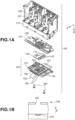
- FIG. 1A is an exploded perspective diagram illustrating a liquid ejection head 100 according to the present exemplary embodiment.
- FIG. 1B a diagram schematically illustrating a cross section of a configuration in the vicinity of an ejection orifice 123 of an element substrate 155 from which a liquid is ejected.
- the liquid ejection head 100 mainly includes a sub tank 120, a housing 110, a flow path member 130, and a recording element unit 150, and these members are fixed to each other by fixing members 160. In the present exemplary embodiment, screws are used as the fixing members 160.
- the sub tank 120 is a tank for storing a liquid (ink) supplied from a main tank (not illustrated), in which the liquid is stored, in the liquid ejection head 100.
- the flow path member 130 has a flow path 131 for supplying the liquid from the sub tank 120 to an element substrate 155.
- the recording element unit 150 includes the element substrate 155 that ejects the liquid therefrom, a support member 151 that supports the element substrate 155, and a flexible substrate 157 electrically connected to the element substrate 155.
- the support member 151 is in contact with the element substrate 155 by use of an adhesive agent (not illustrated).
- the support member 151 may be made of, for example, an alloy of iron and stainless steel material (SUS), such as carbon steel (S45C), an inorganic material such as silicon, ceramics, or a resin material such as an epoxy resin.
- SUS alloy of iron and stainless steel material
- S45C carbon steel
- the support member 151 is desirably resistant to corrosion.
- a sealing member 140 is provided between the flow path member 130 and the recording element unit 150.
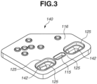
- the sealing member 140 includes damper portions 142 for absorbing (restraining) vibration of the liquid, and a sealing portion 115 for preventing leakage of the liquid.
- the damper portions 142 are formed of a flexible material. More specifically, examples of the flexible material include a resin material such as an epoxy resin, a thermoplastic elastomer, a thermoset elastomer, and silicone rubber.
- the damper portions 142 only need to contain at least one of these resin materials. With the damper portions 142 provided inside a liquid chamber 101 (see FIG. 4 ), the vibration of the liquid inside the liquid chamber 101 can be restrained by the damper portions 142 being deformable according to the vibration of the liquid.
- the sealing portion 115 is also formed of a flexible material, similarly. More specifically, examples of the flexible material include a resin material such as an epoxy resin, a thermoplastic elastomer, a thermoset elastomer, and silicone rubber. The sealing portion 115 only needs to contain at least one of these resin materials. The sealing portion 115 prevents leakage of the liquid from a portion between the flow path 131 of the flow path member 130 and the recording element unit 150. The liquid supplied from the main tank flows or passes through the flow path member 130, the sealing portion 115 of the sealing member 140, a supply port 152 of the support member 151, and the liquid chamber 101 in this order and then is supplied to the ejection orifice 123. A portion 116 of the sealing member 140 other than that damper portions 142 and the sealing portion 115 is formed of a non-flexible material (such as plastic or metal). That is, the sealing member 140 consists of a flexible member and a non-flexible member.
- the element substrate 155 is provided with an energy-generating element 124 configured to generate energy for ejecting the liquid from the ejection orifice 123.
- an energy-generating element 124 configured to generate energy for ejecting the liquid from the ejection orifice 123.
- FIG. 1B illustrates a heat-generating element as an example of the energy-generating element 124
- the energy-generating element according to the present exemplary embodiment is not limited thereto. That is, a piezoelectric element may be used as the energy-generating element 124 instead.
- Driving the energy-generating element 124 causes film boiling of the liquid, and then the liquid is ejected from the ejection orifice 123.
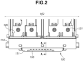
- FIG. 2 is a front view of a part of the liquid ejection head 100 in FIGS. 1A and 1B in a state where the liquid ejection head 100 is finished.
- FIG. 3 is a perspective view illustrating the sealing member 140.
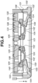
- FIG. 4 is a cross-sectional diagram illustrating a cross section taken along A-A in FIG. 2 .
- the liquid is supplied from the main tank to the liquid chamber 101 via a tube (not illustrated) connected to a liquid connecting portion 121.
- the sealing member 140 is provided on a second surface 103 of the support member 151, which is a back surface of a surface 102 (first surface) of the support member 151 on which the element substrate 155 is supported.
- the sealing member 140 is provided in such a way that the damper portions 142 of the sealing member 140 close through-holes 154.
- the liquid chamber 101 has a shape that tilts with respect to the first surface 102 supporting the element substrate 155 such that a cross-sectional area of the liquid chamber 101 gradually increases from the upper side toward the bottom side in a vertical direction (in a Z direction) (hereinafter, the liquid chamber 101 is also referred to as a triangular liquid chamber 101).
- the liquid chamber 101 having the shape, it is possible to prevent turbulence of the liquid flowing in the vicinity of wall surfaces of the liquid chamber 101 after the liquid is supplied from the supply port 152 into the liquid chamber 101. As a result, it can prevent the air bubbles that have entered the liquid chamber 101 from accumulating in the vicinity of the wall surface (ceiling) of the liquid chamber 101.
- the damper portions 142 are formed in such a way that the damper portions 142 are tightly in contact with the support member 151. Accordingly, the through-holes 154 are formed so as to communicate with the liquid chamber 101 at positions that are located above the liquid chamber 101 in the vertical direction when the liquid ejection head 100 is in an orientation in use (orientation illustrated in FIG. 4 ).
- An abutting portion 125 is provided (abutted) on the surface (second surface) 103 on the flow path member side of the support member 151, which corresponds to an upper surface of the support member 151.
- the abutting portion 125 is formed of the same material as that of the damper portions 142 and integrally formed with the damper portions 142.
- the support member 151 and the damper portions 142 are firmly fixed to each other by using the fixing members 160 (see FIGS. 1A and 1B ). In this way, the support member 151 and the damper portions 142 are firmly fixed to each other by stresses that the support member 151 and the damper portion 142 mutually apply to each other by the fixing members 160 in a state where the damper portions 142 are provided on the ceiling 159 of the liquid chamber 101. This makes it possible to form the liquid chamber 101 with the support member 151 and the damper portions 142 tightly in contact with each other, thereby having high adhesion therebetween.
- the damper portions 142 each have such a shape that tapers downwardly in the vertical direction in the orientation illustrated in FIG. 4 .
- the damper portions 142 with this shape are provided in such a way that the damper portions 142 close the through-holes 154 of the support member 151, thereby making it possible to prevent a formation of such a recess portion that can possibly include air bubbles therein inside the liquid chamber 101. Therefore, according to the present exemplary embodiment, it is possible to form the liquid chamber 101 that can reduce accumulation of air bubbles inside the liquid chamber 101, while assuring high adhesion between the support member 151 and the damper portions 142 that are tightly in contact with each other.
- FIG. 7 is a flowchart illustrating a manufacturing process of manufacturing the liquid ejection head 100.
- a support member 151 with through-holes 154 formed therein is prepared.
- damper portions 142 each having a shape that tapers downwardly in the vertical direction are prepared.
- the damper portions 142 are positioned on the support member 151 in the vertical direction in such a way that the tapered-shaped portions of the damper portions 142 close the through-holes 154 of the support member 151.
- the support member 151 and the damper portions 142 are attached to each other by fixing members 160.
- a liquid ejection head 100 is manufactured.
- the support member 151 and the damper portions 142 are firmly fixed to each other while mutually applying stresses to each other, thereby assuring high adhesion between the support member 151 and the damper portions 142 that are tightly in contact with each other.
- the damper portions 142 close the through-holes 154. Accordingly, it becomes possible to prevent a formation of such an undesirable recess portion (gap) inside the liquid chamber 101 where air bubbles can accumulate therein, thereby making it possible to prevent the air bubbles stay inside the liquid chamber 101.
- FIG. 5A is a top view illustrating the flow path member 130.
- FIG. 5B is a view illustrating a modification of the flow path member 130 illustrated in FIG. 5A .
- Space portions 106 for communicating with atmosphere are formed on a back side of the surface of each damper portion 142 facing the liquid chamber 101. This configuration allows the damper portions 142 to be easily deformable.
- An atmosphere communication path 113 for communicating with the space portions 106 and atmosphere is formed in the flow path member 130.
- a first atmosphere communication path 113a and a second atmosphere communication path 113b are formed in the flow path member 130.
- the first atmosphere communication path 113a is an atmosphere communication path connected with a space portion 106 (first space portion) on the back surface side of a damper portion 142 (first damper portion) that is illustrated as a right one of the two damper portions 142 in FIG. 4 .
- the second atmosphere communication path 113b is an atmosphere communication path connected with a space portion 106 (second space portion) on the back surface side of a damper portion 142 (second damper portion) that is illustrated as a left one of the two damper portions 142 in FIG. 4 . That is, the space portions 106 on the back surface side of the damper portions 142 are open to the atmosphere via the atmosphere communication path 113.
- a volatile component of the liquid in the liquid chamber 101 gradually transmits through the damper portions 142 over time and moves into the atmosphere communication path 113. Because the atmosphere communication path 113 communicate with the atmosphere, the volatile component of the liquid in the liquid chamber 101 gradually evaporates via the atmosphere communication path 113.
- a greater cross-sectional area of the atmosphere communication path 113 results in a greater amount of evaporation of the liquid, and a longer length of the atmosphere communication path 113 results in a smaller amount of evaporation of the liquid.
- the first and second atmosphere communication path 113 is bent plural times, so that the length of the atmosphere communication path 113 is increased. In FIG. 5A , flow paths of the first and second atmosphere communication paths 113a and 113b are merged into each other. This makes it possible to form the longer atmosphere communication path 113 in a smaller region.
- first and second atmosphere communication paths 113a and 113b may be independently formed (without merging into each other) as illustrated in FIG. 5B .
- FIG. 5B it becomes possible to prevent a pressure change in one space portion 106 (the first space portion) from affecting the pressure in the other space portion 106 (the second space portion), so that the damper portions 142 can stably restrain the vibration of the liquid.
- the space portions 106 may not be communicated with the atmosphere, even though the space portions 106 have been described to be communicated with the atmosphere in the above description. That is, the space portions 106 may be closed spaces. If the space portions 106 have a certain volume, the damper portions 142 can deform according to the vibration of the liquid, thereby functioning as a damper even if the space portions 106 are closed spaces. However, if the space portions 106 are closed spaces, the pressures in the space portions 106 will change in such a way that the pressures change to prevent the deformation of the damper portions 142 when the damper portions 142 is/are vibrated according to the vibration of the liquid.
- the pressures in the space portions 106 be kept constant in order to prevent such a phenomenon that the pressure changes inside the space portions 106 hinder the deformation of the damper portions 142. That is, it is more desirable that the space portions 106 are communicated with the atmosphere.
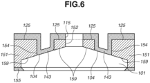
- FIG. 6 is a diagram schematically illustrating a case where damper portions 143 are provided on a ceiling 159 of a liquid chamber 101 according to the second exemplary embodiment.
- the damper portions 143 according to the second exemplary embodiment are provided in such a way that a surface having a convex shape (lower surface) 104 of each of the damper portions 143 tilts along a slant surface of the ceiling 159 of the triangular liquid chamber 101.
- tilt along is that a slant angle of the ceiling 159 with respect to an element substrate 155 and a slant angle of the lower surface 104 of the damper portion 143 with respect to the element substrate 155 are substantially equal to each other and the lower surface 104 is an extension of the plane of the ceiling 159.
- substantially equal angles is that a difference between the slant angle of the ceiling 159 on the assumption that the ceiling 159 is flat and the slant angle of the lower surface 104 on the assumption that the lower surface 104 is flat is within 10 degrees.
- each gap between through-holes 154 and the damper portions 143 can be minimized. This makes it possible to prevent such a phenomenon that air bubbles that have entered into the liquid chamber 101 are caught in the gaps between the damper portions 143 and the through-holes 154 and then kept inside the liquid chamber 101 which can cause the air bubbles to enter the ejection orifice 123 as a result.
Landscapes
- Engineering & Computer Science (AREA)
- Manufacturing & Machinery (AREA)
- Particle Formation And Scattering Control In Inkjet Printers (AREA)
- Ink Jet (AREA)
Claims (15)
- Flüssigkeitsausstoßkopf (100), umfassend:ein Elementsubstrat (155) mit einem energieerzeugenden Element (124), das konfiguriert ist, eine Energie zum Ausstoßen einer Flüssigkeit aus einer Ausstoßöffnung (123) zu erzeugen;ein Halteelement (151) zum Halten des Elementsubstrats, wobei das Halteelement eine darin ausgebildete Flüssigkeitskammer (101) enthält, um die Flüssigkeit der Ausstoßöffnung zuzuführen; undeinen Dämpferabschnitt (142) zum Absorbieren von Schwingungen der Flüssigkeit in der Flüssigkeitskammer, wobei der Dämpferabschnitt flexibel ist,wobei das Halteelement ein Durchgangsloch (154) zum Kommunizieren mit der Flüssigkeitskammer an einer Position aufweist, die sich in einer vertikalen Richtung über der Flüssigkeitskammer befindet, wenn sich der Flüssigkeitsausstoßkopf in einer Verwendungsausrichtung befindet,dadurch gekennzeichnet, dassder Dämpferabschnitt einen sich verjüngenden Abschnitt aufweist, der sich in der vertikalen Richtung nach unten verjüngt und derart positioniert ist, dass der sich verjüngende Abschnitt das Durchgangsloch schließt, undder Dämpferabschnitt und das Halteelement durch ein Befestigungselement (160) aneinander befestigt sind.
- Flüssigkeitsausstoßkopf nach Anspruch 1, wobei der Dämpferabschnitt aus einem Harzmaterial hergestellt ist, das mindestens eines von einem Epoxidharz, einem thermoplastischen Elastomer, einem duroplastischen Elastomer oder Silikonkautschuk enthält.
- Flüssigkeitsausstoßkopf nach Anspruch 1 oder 2, ferner umfassend: ein Strömungswegelement (130) mit einem Strömungsweg zum Zuführen der Flüssigkeit zur Flüssigkeitskammer,wobei der Dämpferabschnitt zwischen dem Strömungswegelement und dem Halteelement vorgesehen ist, undwobei der Dämpferabschnitt und das Halteelement durch das Befestigungselement in einem Zustand aneinander befestigt sind, in dem ein mit dem Dämpferabschnitt verbundener Anliegeabschnitt (125) an einer Oberfläche des Halteelements auf einer Strömungswegelementseite anliegt.
- Flüssigkeitsausstoßkopf nach Anspruch 3,wobei eine Zuführöffnung (152), welche mit dem Strömungsweg des Strömungswegelements kommuniziert, in der Flüssigkeitskammer ausgebildet ist,wobei ein Dichtungselement (140) mit einem Dichtungsabschnitt (115) zum Verbinden des Strömungswegs und der Zuführöffnung miteinander durch Abdichten des Strömungswegs und der Zuführöffnung zwischen dem Strömungswegelement und dem Halteelement vorgesehen ist, undwobei der Dämpferabschnitt und der Anliegeabschnitt im Dichtungselement ausgebildet sind.
- Flüssigkeitsausstoßkopf nach Anspruch 3 oder 4, wobei der Anliegeabschnitt aus einem Harzmaterial hergestellt ist, das mindestens eines von einem Epoxidharz, einem thermoplastischen Elastomer, einem duroplastischen Elastomer oder Silikonkautschuk enthält.
- Flüssigkeitsausstoßkopf nach einem der Ansprüche 1 bis 5, wobei die Flüssigkeitskammer eine derartige Form aufweist, dass ihre Querschnittsfläche in der vertikalen Richtung von einer oberen Seite zu einer unteren Seite allmählich zunimmt.
- Flüssigkeitsausstoßkopf nach Anspruch 6, wobei eine Oberfläche (159), die eine Wand der Flüssigkeitskammer auf der oberen Seite in der vertikalen Richtung ausbildet, in Bezug auf eine Oberfläche des Halteelements, welches das Elementsubstrat hält, geneigt ist.
- Flüssigkeitsausstoßkopf nach Anspruch 7, wobei eine Oberfläche des sich verjüngenden Abschnitts des Dämpferabschnitts in Bezug auf die Oberfläche des Halteelements, welches das Elementsubstrat hält, geneigt ist.
- Flüssigkeitsausstoßkopf nach Anspruch 8, wobei die Oberfläche des sich verjüngenden Abschnitts des Dämpferabschnitts eine Verlängerung der Oberfläche ist, welche die Wand der Flüssigkeitskammer auf der oberen Seite in der vertikalen Richtung ausbildet.
- Flüssigkeitsausstoßkopf nach einem der Ansprüche 1 bis 6, wobei eine Oberfläche des sich verjüngenden Abschnitts des Dämpferabschnitts entlang einer Oberfläche des Halteelements, welches das Elementsubstrat hält, angeordnet ist.
- Flüssigkeitsausstoßkopf nach einem der Ansprüche 1 bis 10, wobei das Befestigungselement eine Schraube ist.
- Flüssigkeitsausstoßkopf nach einem der Ansprüche 1 bis 11, wobei das Halteelement mit dem Elementsubstrat in Kontakt ist.
- Flüssigkeitsausstoßkopf nach einem der Ansprüche 1 bis 12, wobei ein Raumabschnitt (106) auf einer Rückseite einer Oberfläche des Dämpferabschnitts, welche der Flüssigkeitskammer zugewandt ist, ausgebildet ist.
- Flüssigkeitsausstoßkopf nach Anspruch 13, wobei der Raumabschnitt mit der Atmosphäre kommuniziert.
- Flüssigkeitsausstoßkopf nach Anspruch 13,wobei der Raumabschnitt mit einem Atmosphärenkommunikationsweg (113) verbunden ist, welcher mit der Atmosphäre kommuniziert, undwobei der Atmosphärenkommunikationsweg mehrmals gebogen ist.
Applications Claiming Priority (1)
| Application Number | Priority Date | Filing Date | Title |
|---|---|---|---|
| JP2019234621A JP7409605B2 (ja) | 2019-12-25 | 2019-12-25 | 液体吐出ヘッドおよび液体吐出ヘッドの製造方法 |
Publications (2)
| Publication Number | Publication Date |
|---|---|
| EP3842235A1 EP3842235A1 (de) | 2021-06-30 |
| EP3842235B1 true EP3842235B1 (de) | 2023-08-30 |
Family
ID=73854638
Family Applications (1)
| Application Number | Title | Priority Date | Filing Date |
|---|---|---|---|
| EP20214298.0A Active EP3842235B1 (de) | 2019-12-25 | 2020-12-15 | Flüssigkeitsausstosskopf |
Country Status (4)
| Country | Link |
|---|---|
| US (1) | US11458732B2 (de) |
| EP (1) | EP3842235B1 (de) |
| JP (1) | JP7409605B2 (de) |
| CN (1) | CN113103763B (de) |
Family Cites Families (19)
| Publication number | Priority date | Publication date | Assignee | Title |
|---|---|---|---|---|
| JP4138214B2 (ja) * | 2000-07-31 | 2008-08-27 | セイコーエプソン株式会社 | 液体噴射装置 |
| JP3606282B2 (ja) | 2001-11-12 | 2005-01-05 | セイコーエプソン株式会社 | 液体噴射装置 |
| JP3768973B2 (ja) | 2002-05-17 | 2006-04-19 | キヤノン株式会社 | インクジェット記録ヘッドおよびインクジェット記録ヘッドの製造方法 |
| JP4539819B2 (ja) | 2003-10-24 | 2010-09-08 | ブラザー工業株式会社 | インクジェットプリンタ |
| US7303271B2 (en) | 2003-10-24 | 2007-12-04 | Brother Kogyo Kabushiki Kaisha | Ink jet printer |
| JP4941483B2 (ja) | 2009-02-25 | 2012-05-30 | ブラザー工業株式会社 | ダンパー装置 |
| JP5707806B2 (ja) | 2010-09-16 | 2015-04-30 | 株式会社リコー | 液体吐出ヘッド及び画像形成装置 |
| JP2012143975A (ja) * | 2011-01-13 | 2012-08-02 | Ricoh Co Ltd | 液体吐出ヘッド、振動板部材の製造方法及び画像形成装置 |
| JP5621684B2 (ja) * | 2011-03-29 | 2014-11-12 | セイコーエプソン株式会社 | 液体噴射ヘッドユニットおよび液体噴射装置 |
| JP5799554B2 (ja) | 2011-04-05 | 2015-10-28 | セイコーエプソン株式会社 | 液体噴射ヘッド、および、液体噴射装置 |
| JP5847482B2 (ja) * | 2011-08-05 | 2016-01-20 | キヤノン株式会社 | インクジェット記録ヘッド |
| JP6349763B2 (ja) | 2013-10-23 | 2018-07-04 | 株式会社リコー | 液滴吐出ヘッドおよび画像形成装置 |
| JP6458928B2 (ja) | 2014-03-28 | 2019-01-30 | セイコーエプソン株式会社 | 液体吐出ヘッド、液体吐出装置および液体吐出ヘッドの制御方法 |
| JP6415114B2 (ja) | 2014-05-30 | 2018-10-31 | キヤノン株式会社 | 液体貯留ユニットとそれを用いた液体吐出装置及び液体貯留ユニットからの気泡の除去方法 |
| JP6516612B2 (ja) | 2015-07-24 | 2019-05-22 | キヤノン株式会社 | 液体吐出ヘッド及び液体吐出装置 |
| US10442188B2 (en) * | 2016-02-10 | 2019-10-15 | Seiko Epson Corporation | Liquid ejecting head and liquid ejecting apparatus |
| JP6707890B2 (ja) | 2016-02-18 | 2020-06-10 | 株式会社リコー | 液体吐出ヘッド、液体吐出ユニット、液体を吐出する装置 |
| JP7027691B2 (ja) * | 2017-03-17 | 2022-03-02 | セイコーエプソン株式会社 | 可撓膜機構、流路部材及び液体噴射装置 |
| JP7118700B2 (ja) | 2018-03-30 | 2022-08-16 | キヤノン株式会社 | 画像形成装置および画像形成装置の制御方法 |
-
2019
- 2019-12-25 JP JP2019234621A patent/JP7409605B2/ja active Active
-
2020
- 2020-12-09 US US17/116,945 patent/US11458732B2/en active Active
- 2020-12-15 EP EP20214298.0A patent/EP3842235B1/de active Active
- 2020-12-22 CN CN202011530021.6A patent/CN113103763B/zh active Active
Also Published As
| Publication number | Publication date |
|---|---|
| US11458732B2 (en) | 2022-10-04 |
| EP3842235A1 (de) | 2021-06-30 |
| US20210197566A1 (en) | 2021-07-01 |
| JP2021102305A (ja) | 2021-07-15 |
| CN113103763A (zh) | 2021-07-13 |
| JP7409605B2 (ja) | 2024-01-09 |
| CN113103763B (zh) | 2023-02-24 |
Similar Documents
| Publication | Publication Date | Title |
|---|---|---|
| US7690754B2 (en) | Inkjet printer head and inkjet printer | |
| US6976753B2 (en) | Liquid container and ink jet printing apparatus | |
| US20090244223A1 (en) | Liquid container and membrane valve | |
| JP3262075B2 (ja) | インクジェット記録ヘッド | |
| EP3842235B1 (de) | Flüssigkeitsausstosskopf | |
| JP7283116B2 (ja) | 液体吐出ヘッドおよび液体吐出装置 | |
| JP2000177119A (ja) | インクジェット式記録ヘッド | |
| US6113226A (en) | Laminated ink jet recording head resolving residual vibration problems in the common ink chamber by setting the natural resonance and driving frequency ranges | |
| JP6648459B2 (ja) | 液体噴射ヘッドおよび液体噴射装置 | |
| EP3372407A1 (de) | Tintenstrahldruckkopfanordnung und verfahren zur herstellung solch eines tintenstrahldruckkopfes | |
| EP3939792B1 (de) | Flüssigkeitszuführelement und flüssigkeitsausstosskopf | |
| JPH1158739A (ja) | インクジェット式記録ヘッド | |
| EP4497598A1 (de) | Druckkopf | |
| JP5402687B2 (ja) | 液体噴射ヘッド、及び、液体噴射装置 | |
| JP3108970B2 (ja) | インクジェット装置 | |
| JP2002086713A (ja) | オンデマンド型インクジェットプリントヘッド | |
| JP2009056723A (ja) | 流体噴射ヘッド及び流体噴射装置 | |
| WO2025021411A1 (en) | Printhead | |
| JP6783086B2 (ja) | インクジェット記録装置及びインクジェット記録装置におけるダンパー機構 | |
| WO2025021413A1 (en) | Printhead | |
| WO2025021412A1 (en) | Printhead | |
| JP2013022810A (ja) | 液体導入ユニット、液体噴射ヘッドユニット、及び、液体噴射装置 | |
| JP2004175119A (ja) | インクジェット式記録ヘッド | |
| JP2004009432A (ja) | インクジェット記録ヘッド | |
| JP2013018250A (ja) | 液体導入ユニット、液体噴射ヘッドユニット、及び、液体導入ユニットの製造方法 |
Legal Events
| Date | Code | Title | Description |
|---|---|---|---|
| PUAI | Public reference made under article 153(3) epc to a published international application that has entered the european phase |
Free format text: ORIGINAL CODE: 0009012 |
|
| STAA | Information on the status of an ep patent application or granted ep patent |
Free format text: STATUS: THE APPLICATION HAS BEEN PUBLISHED |
|
| AK | Designated contracting states |
Kind code of ref document: A1 Designated state(s): AL AT BE BG CH CY CZ DE DK EE ES FI FR GB GR HR HU IE IS IT LI LT LU LV MC MK MT NL NO PL PT RO RS SE SI SK SM TR |
|
| STAA | Information on the status of an ep patent application or granted ep patent |
Free format text: STATUS: REQUEST FOR EXAMINATION WAS MADE |
|
| 17P | Request for examination filed |
Effective date: 20220103 |
|
| RBV | Designated contracting states (corrected) |
Designated state(s): AL AT BE BG CH CY CZ DE DK EE ES FI FR GB GR HR HU IE IS IT LI LT LU LV MC MK MT NL NO PL PT RO RS SE SI SK SM TR |
|
| RIC1 | Information provided on ipc code assigned before grant |
Ipc: B41J 2/19 20060101ALI20230131BHEP Ipc: B41J 2/055 20060101AFI20230131BHEP |
|
| GRAP | Despatch of communication of intention to grant a patent |
Free format text: ORIGINAL CODE: EPIDOSNIGR1 |
|
| STAA | Information on the status of an ep patent application or granted ep patent |
Free format text: STATUS: GRANT OF PATENT IS INTENDED |
|
| INTG | Intention to grant announced |
Effective date: 20230329 |
|
| GRAS | Grant fee paid |
Free format text: ORIGINAL CODE: EPIDOSNIGR3 |
|
| GRAA | (expected) grant |
Free format text: ORIGINAL CODE: 0009210 |
|
| STAA | Information on the status of an ep patent application or granted ep patent |
Free format text: STATUS: THE PATENT HAS BEEN GRANTED |
|
| AK | Designated contracting states |
Kind code of ref document: B1 Designated state(s): AL AT BE BG CH CY CZ DE DK EE ES FI FR GB GR HR HU IE IS IT LI LT LU LV MC MK MT NL NO PL PT RO RS SE SI SK SM TR |
|
| REG | Reference to a national code |
Ref country code: GB Ref legal event code: FG4D |
|
| REG | Reference to a national code |
Ref country code: CH Ref legal event code: EP |
|
| REG | Reference to a national code |
Ref country code: DE Ref legal event code: R096 Ref document number: 602020016644 Country of ref document: DE |
|
| REG | Reference to a national code |
Ref country code: IE Ref legal event code: FG4D |
|
| REG | Reference to a national code |
Ref country code: LT Ref legal event code: MG9D |
|
| REG | Reference to a national code |
Ref country code: NL Ref legal event code: MP Effective date: 20230830 |
|
| REG | Reference to a national code |
Ref country code: AT Ref legal event code: MK05 Ref document number: 1604955 Country of ref document: AT Kind code of ref document: T Effective date: 20230830 |
|
| PG25 | Lapsed in a contracting state [announced via postgrant information from national office to epo] |
Ref country code: GR Free format text: LAPSE BECAUSE OF FAILURE TO SUBMIT A TRANSLATION OF THE DESCRIPTION OR TO PAY THE FEE WITHIN THE PRESCRIBED TIME-LIMIT Effective date: 20231201 |
|
| PG25 | Lapsed in a contracting state [announced via postgrant information from national office to epo] |
Ref country code: IS Free format text: LAPSE BECAUSE OF FAILURE TO SUBMIT A TRANSLATION OF THE DESCRIPTION OR TO PAY THE FEE WITHIN THE PRESCRIBED TIME-LIMIT Effective date: 20231230 |
|
| PG25 | Lapsed in a contracting state [announced via postgrant information from national office to epo] |
Ref country code: SE Free format text: LAPSE BECAUSE OF FAILURE TO SUBMIT A TRANSLATION OF THE DESCRIPTION OR TO PAY THE FEE WITHIN THE PRESCRIBED TIME-LIMIT Effective date: 20230830 Ref country code: RS Free format text: LAPSE BECAUSE OF FAILURE TO SUBMIT A TRANSLATION OF THE DESCRIPTION OR TO PAY THE FEE WITHIN THE PRESCRIBED TIME-LIMIT Effective date: 20230830 Ref country code: NO Free format text: LAPSE BECAUSE OF FAILURE TO SUBMIT A TRANSLATION OF THE DESCRIPTION OR TO PAY THE FEE WITHIN THE PRESCRIBED TIME-LIMIT Effective date: 20231130 Ref country code: LV Free format text: LAPSE BECAUSE OF FAILURE TO SUBMIT A TRANSLATION OF THE DESCRIPTION OR TO PAY THE FEE WITHIN THE PRESCRIBED TIME-LIMIT Effective date: 20230830 Ref country code: LT Free format text: LAPSE BECAUSE OF FAILURE TO SUBMIT A TRANSLATION OF THE DESCRIPTION OR TO PAY THE FEE WITHIN THE PRESCRIBED TIME-LIMIT Effective date: 20230830 Ref country code: IS Free format text: LAPSE BECAUSE OF FAILURE TO SUBMIT A TRANSLATION OF THE DESCRIPTION OR TO PAY THE FEE WITHIN THE PRESCRIBED TIME-LIMIT Effective date: 20231230 Ref country code: HR Free format text: LAPSE BECAUSE OF FAILURE TO SUBMIT A TRANSLATION OF THE DESCRIPTION OR TO PAY THE FEE WITHIN THE PRESCRIBED TIME-LIMIT Effective date: 20230830 Ref country code: GR Free format text: LAPSE BECAUSE OF FAILURE TO SUBMIT A TRANSLATION OF THE DESCRIPTION OR TO PAY THE FEE WITHIN THE PRESCRIBED TIME-LIMIT Effective date: 20231201 Ref country code: FI Free format text: LAPSE BECAUSE OF FAILURE TO SUBMIT A TRANSLATION OF THE DESCRIPTION OR TO PAY THE FEE WITHIN THE PRESCRIBED TIME-LIMIT Effective date: 20230830 Ref country code: AT Free format text: LAPSE BECAUSE OF FAILURE TO SUBMIT A TRANSLATION OF THE DESCRIPTION OR TO PAY THE FEE WITHIN THE PRESCRIBED TIME-LIMIT Effective date: 20230830 |
|
| PG25 | Lapsed in a contracting state [announced via postgrant information from national office to epo] |
Ref country code: PL Free format text: LAPSE BECAUSE OF FAILURE TO SUBMIT A TRANSLATION OF THE DESCRIPTION OR TO PAY THE FEE WITHIN THE PRESCRIBED TIME-LIMIT Effective date: 20230830 Ref country code: NL Free format text: LAPSE BECAUSE OF FAILURE TO SUBMIT A TRANSLATION OF THE DESCRIPTION OR TO PAY THE FEE WITHIN THE PRESCRIBED TIME-LIMIT Effective date: 20230830 |
|
| PG25 | Lapsed in a contracting state [announced via postgrant information from national office to epo] |
Ref country code: ES Free format text: LAPSE BECAUSE OF FAILURE TO SUBMIT A TRANSLATION OF THE DESCRIPTION OR TO PAY THE FEE WITHIN THE PRESCRIBED TIME-LIMIT Effective date: 20230830 |
|
| PG25 | Lapsed in a contracting state [announced via postgrant information from national office to epo] |
Ref country code: SM Free format text: LAPSE BECAUSE OF FAILURE TO SUBMIT A TRANSLATION OF THE DESCRIPTION OR TO PAY THE FEE WITHIN THE PRESCRIBED TIME-LIMIT Effective date: 20230830 Ref country code: RO Free format text: LAPSE BECAUSE OF FAILURE TO SUBMIT A TRANSLATION OF THE DESCRIPTION OR TO PAY THE FEE WITHIN THE PRESCRIBED TIME-LIMIT Effective date: 20230830 Ref country code: ES Free format text: LAPSE BECAUSE OF FAILURE TO SUBMIT A TRANSLATION OF THE DESCRIPTION OR TO PAY THE FEE WITHIN THE PRESCRIBED TIME-LIMIT Effective date: 20230830 Ref country code: EE Free format text: LAPSE BECAUSE OF FAILURE TO SUBMIT A TRANSLATION OF THE DESCRIPTION OR TO PAY THE FEE WITHIN THE PRESCRIBED TIME-LIMIT Effective date: 20230830 Ref country code: DK Free format text: LAPSE BECAUSE OF FAILURE TO SUBMIT A TRANSLATION OF THE DESCRIPTION OR TO PAY THE FEE WITHIN THE PRESCRIBED TIME-LIMIT Effective date: 20230830 Ref country code: CZ Free format text: LAPSE BECAUSE OF FAILURE TO SUBMIT A TRANSLATION OF THE DESCRIPTION OR TO PAY THE FEE WITHIN THE PRESCRIBED TIME-LIMIT Effective date: 20230830 Ref country code: SK Free format text: LAPSE BECAUSE OF FAILURE TO SUBMIT A TRANSLATION OF THE DESCRIPTION OR TO PAY THE FEE WITHIN THE PRESCRIBED TIME-LIMIT Effective date: 20230830 Ref country code: PT Free format text: LAPSE BECAUSE OF FAILURE TO SUBMIT A TRANSLATION OF THE DESCRIPTION OR TO PAY THE FEE WITHIN THE PRESCRIBED TIME-LIMIT Effective date: 20240102 |
|
| PG25 | Lapsed in a contracting state [announced via postgrant information from national office to epo] |
Ref country code: IT Free format text: LAPSE BECAUSE OF FAILURE TO SUBMIT A TRANSLATION OF THE DESCRIPTION OR TO PAY THE FEE WITHIN THE PRESCRIBED TIME-LIMIT Effective date: 20230830 |
|
| REG | Reference to a national code |
Ref country code: DE Ref legal event code: R097 Ref document number: 602020016644 Country of ref document: DE |
|
| PLBE | No opposition filed within time limit |
Free format text: ORIGINAL CODE: 0009261 |
|
| STAA | Information on the status of an ep patent application or granted ep patent |
Free format text: STATUS: NO OPPOSITION FILED WITHIN TIME LIMIT |
|
| PG25 | Lapsed in a contracting state [announced via postgrant information from national office to epo] |
Ref country code: SI Free format text: LAPSE BECAUSE OF FAILURE TO SUBMIT A TRANSLATION OF THE DESCRIPTION OR TO PAY THE FEE WITHIN THE PRESCRIBED TIME-LIMIT Effective date: 20230830 |
|
| REG | Reference to a national code |
Ref country code: CH Ref legal event code: PL |
|
| 26N | No opposition filed |
Effective date: 20240603 |
|
| PG25 | Lapsed in a contracting state [announced via postgrant information from national office to epo] |
Ref country code: LU Free format text: LAPSE BECAUSE OF NON-PAYMENT OF DUE FEES Effective date: 20231215 |
|
| PG25 | Lapsed in a contracting state [announced via postgrant information from national office to epo] |
Ref country code: MC Free format text: LAPSE BECAUSE OF FAILURE TO SUBMIT A TRANSLATION OF THE DESCRIPTION OR TO PAY THE FEE WITHIN THE PRESCRIBED TIME-LIMIT Effective date: 20230830 |
|
| REG | Reference to a national code |
Ref country code: BE Ref legal event code: MM Effective date: 20231231 |
|
| PG25 | Lapsed in a contracting state [announced via postgrant information from national office to epo] |
Ref country code: MC Free format text: LAPSE BECAUSE OF FAILURE TO SUBMIT A TRANSLATION OF THE DESCRIPTION OR TO PAY THE FEE WITHIN THE PRESCRIBED TIME-LIMIT Effective date: 20230830 Ref country code: LU Free format text: LAPSE BECAUSE OF NON-PAYMENT OF DUE FEES Effective date: 20231215 |
|
| REG | Reference to a national code |
Ref country code: IE Ref legal event code: MM4A |
|
| PG25 | Lapsed in a contracting state [announced via postgrant information from national office to epo] |
Ref country code: IE Free format text: LAPSE BECAUSE OF NON-PAYMENT OF DUE FEES Effective date: 20231215 |
|
| PG25 | Lapsed in a contracting state [announced via postgrant information from national office to epo] |
Ref country code: BE Free format text: LAPSE BECAUSE OF NON-PAYMENT OF DUE FEES Effective date: 20231231 |
|
| PG25 | Lapsed in a contracting state [announced via postgrant information from national office to epo] |
Ref country code: FR Free format text: LAPSE BECAUSE OF NON-PAYMENT OF DUE FEES Effective date: 20231231 |
|
| PG25 | Lapsed in a contracting state [announced via postgrant information from national office to epo] |
Ref country code: CH Free format text: LAPSE BECAUSE OF NON-PAYMENT OF DUE FEES Effective date: 20231231 |
|
| PG25 | Lapsed in a contracting state [announced via postgrant information from national office to epo] |
Ref country code: IE Free format text: LAPSE BECAUSE OF NON-PAYMENT OF DUE FEES Effective date: 20231215 Ref country code: FR Free format text: LAPSE BECAUSE OF NON-PAYMENT OF DUE FEES Effective date: 20231231 Ref country code: CH Free format text: LAPSE BECAUSE OF NON-PAYMENT OF DUE FEES Effective date: 20231231 Ref country code: BE Free format text: LAPSE BECAUSE OF NON-PAYMENT OF DUE FEES Effective date: 20231231 |
|
| PG25 | Lapsed in a contracting state [announced via postgrant information from national office to epo] |
Ref country code: BG Free format text: LAPSE BECAUSE OF FAILURE TO SUBMIT A TRANSLATION OF THE DESCRIPTION OR TO PAY THE FEE WITHIN THE PRESCRIBED TIME-LIMIT Effective date: 20230830 |
|
| PG25 | Lapsed in a contracting state [announced via postgrant information from national office to epo] |
Ref country code: BG Free format text: LAPSE BECAUSE OF FAILURE TO SUBMIT A TRANSLATION OF THE DESCRIPTION OR TO PAY THE FEE WITHIN THE PRESCRIBED TIME-LIMIT Effective date: 20230830 |
|
| PG25 | Lapsed in a contracting state [announced via postgrant information from national office to epo] |
Ref country code: CY Free format text: LAPSE BECAUSE OF FAILURE TO SUBMIT A TRANSLATION OF THE DESCRIPTION OR TO PAY THE FEE WITHIN THE PRESCRIBED TIME-LIMIT; INVALID AB INITIO Effective date: 20201215 |
|
| PG25 | Lapsed in a contracting state [announced via postgrant information from national office to epo] |
Ref country code: HU Free format text: LAPSE BECAUSE OF FAILURE TO SUBMIT A TRANSLATION OF THE DESCRIPTION OR TO PAY THE FEE WITHIN THE PRESCRIBED TIME-LIMIT; INVALID AB INITIO Effective date: 20201215 |
|
| GBPC | Gb: european patent ceased through non-payment of renewal fee |
Effective date: 20241215 |
|
| PG25 | Lapsed in a contracting state [announced via postgrant information from national office to epo] |
Ref country code: GB Free format text: LAPSE BECAUSE OF NON-PAYMENT OF DUE FEES Effective date: 20241215 |
|
| PG25 | Lapsed in a contracting state [announced via postgrant information from national office to epo] |
Ref country code: TR Free format text: LAPSE BECAUSE OF FAILURE TO SUBMIT A TRANSLATION OF THE DESCRIPTION OR TO PAY THE FEE WITHIN THE PRESCRIBED TIME-LIMIT Effective date: 20230830 |
|
| PGFP | Annual fee paid to national office [announced via postgrant information from national office to epo] |
Ref country code: DE Payment date: 20251126 Year of fee payment: 6 |